1
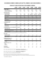
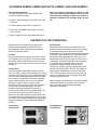
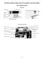
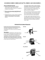
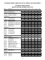
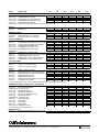
KKSM-3
KOMPAC
SERIES
AIR CONDITIONER
AND HEAT PUMP
INSTALLATION &
OPERATION
MANUAL
KOOLETTE
KOMPAC
Koolette 7,000 Btu/Hr Cooling
KING KOMPAC
7,800 Btu/Hr Heating
Kompac
9,400-16,000 Btu/Hr Cooling
10,900-17,900 Btu/Hr Heating
King Kompac 20,500-26,000 Btu/Hr Cooling
24,000-31,000 Btu/Hr Heating
GENERAL INFORMATION AND
CAPACITY SELECTION ..................................... 1, 2
SPECIFICATIONS .................................................. 3
STANDARD AND OPTIONAL FEATURES ........ 4, 5
INSTALLATION INSTRUCTIONS ...................... 6, 7
CHECKOUT OF UNIT OPERATION ...................... 7
WATER FLOW GRAPH AND
MODES OF OPERATION ................................... 8, 9
UNIT CONSTRUCTION ................................... 10-12
PARTS REPLACEMENT PROCEDURE ........ 13, 14
PREVENTIVE MAINTENANCE ...................... 14, 15
TROUBLESHOOTING GUIDE ....................... 16, 17
PIPING SCHEMATICS ......................................... 18
WIRING DIAGRAMS ...................................... 19, 20
CERTIFIED DRAWINGS ...................................... 21
LIMITED WARRANTY .......................................... 22
PARTS LIST ..................................................... 23,24
GENERAL INFORMATION
DESCRIPTION
Kompac Series Air Conditioners and Heat Pumps are
designed for applications where outside air is not
available and spot cooling is required. The cord
connected Kompac Models range from a 7,000 Btu/Hr
countertop to a 26,000 Btu/Hr floor mount configuration
to meet any space requirements. Kompac and King
Kompac models are provided with casters for portability.
All Models are completely self-contained with the entire
refrigeration system, fan motor, water valve, and
electrical components housed in a metal cabinet with a
baked enamel finish. Only power and condenser water
supply, water discharge, and condensate drain piping
are required for installation. With the heat pump option,
automatic changeover from cooling to heating to cooling
provides the desired comfort, depending upon
thermostat command.
The water-cooled condenser requires only that amount
of water needed to achieve the desired high and low
refrigeration system pressures. The condenser water
flow rate for any entering water temperature can be
obtained using the graph on page 8. Condenser water is
regulated by a refrigeration system head pressure
actuated water regulating valve.
260 NORTH ELM STREET • WESTFIELD, MA 01085 • Tel: (413) 564-5520 • Fax: (413) 564-5815
KOLDWAVE KOMPAC SERIES (KOOLETTE, KOMPAC, AND KING KOMPAC)
GENERAL REQUIREMENTS
For proper control of the water flow rate entering the
automatic water valve, the minimum water pressure
required for condenser water supply is 30 PSIG.
CAPACITY SELECTION
Koldwave Kompac Series Air Conditioners and Heat
Pumps are designed for any type of application with
cooling requirements ranging from 7,000 Btu/Hr with
the Koolette, 9,400 -16,000 Btu/Hr with the Kompac
and 20,500-26,000 Btu/Hr with the King Kompac. Also
heating requirements ranging from 7,800 Btu/Hr with
the Koolette, 10,900-17,900 Btu/Hr with the Kompac
and 24,000-31,000 Btu/Hr with the King Kompac. The
Kompac Series cooling capacity designations are
shown below.
The condenser water temperature leaving the unit
should not exceed 110°F. Ignoring this compliance will
void the warranty on the refrigeration system. On heat
pump models, it is not recommended to operate the
unit in the heating cycle when the water inlet
temperature is below 50°F. Doing so could reduce the
specified heating capacity and may cause the freeze
control to cycle the compressor off, resulting in a loss
of heating.
Capacity Code: 07
10
14
16
20
26
IMPORTANT: Koldwave Air Conditioners have been
designed and engineered with your comfort in mind.
The length of service you can receive can be
extended by following the installation and
preventive maintenance instructions. It is important
that the warranty card be filled out completely and
returned to the factory within ten (10) days of
installation of the unit in order to receive the
benefits of the warranties.
.................................. 7,000 Btu/Hr
.................................. 9,400 Btu/Hr
................................ 12,500 Btu/Hr
................................ 16,000 Btu/Hr
................................ 20,500 Btu/Hr
................................ 26,000 Btu/Hr
Kompac Model designations are:
Prefix K denotes .................... Koldwave Kompac Model
Suffix D denotes ....................... Air Conditioning Model
Suffix H denotes .......................................... Heat Pump
Suffix T denotes ........ Unit for Cooling Tower Operation
Suffix S denotes ......................... Stainless Steel Finish
KOLDWAVE NOMENCLATURE
The Koldwave Kompac Series nomeclature is listed
below which explains the type of unit, the capacity, the
phase, and the voltage.
2 K 14 D H S T 1 1
Series
Koldwave
Capacity Selection
Air Conditioning Model
Heat Pump Option
Number Code: Phase: 1 - Single Ø
Voltage: 1 - 115V
2 - 208/230V
2
115 Volt
Single Phase
Cooling Tower
Model
Type of Finish
KOLDWAVE KOMPAC SERIES (KOOLETTE, KOMPAC, AND KING KOMPAC)
PRODUCT SPECIFICATIONS FOR KOMPAC SERIES
2K07DB
2K07DBH
2K10DB
2K10DHB
2K14DB
2K14DHB
2K16DB
2K16DHB
2K20DB
2K20DHB
2K26DB
2K26DHB
2K26DBL
2K26DHBL
CAPACITY DATA
Cooling Capacity (A)
Heating Capacity (B) & (D)
Evaporator-CFM @ 0.0 ESP
7,000
7,800
250
9,400
10,900
345
12,500
14,200
410
16,000
17,900
480
20,500
24,000
650
26,000
31,000
800
23,200
31,000
800
ELECTRICAL DATA
Volts (Single Phase)
Amperes (Cooling)
Amperes (Heating)
Watts (Cooling)
Watts (Heating)
E.E.R.
C.O.P.
Fuse/Breaker amps
Compressor H.P.
Blower Motor H.P.
In Rush Current (amps)
115
8.00
7.50
897
840
7.80
2.70
15
1
/2
1
/25
45.20
115*
9.8
9.50
1,000
1,065
9.40
3.00
15
3
/4
1
/15
71.50
115*
11.60
10.80
1,276
1,301
9.80
3.20
15
1
1
/15
71.50
115*
13.00
13.00
1,684
1,692
9.50
3.10
20
11/4
1
/15
96.50
208/230
10.40/10.10
10.50/10.10
2,092
2,269
9.80
3.10
15
11/2
1
/7
61.90
208/230
12.70/11.80
12.50/11.50
2,708
2,839
9.60
3.20
20
2
1
/7
72.90
208/230
12.70/11.80
12.50/11.50
2,416
2,839
9.60
3.20
20
2
1
/7
72.90
CONDENSATE PUMP
Motor H.P.
RPM
Voltage
Amperage Draw
Lift (Feet of H2O)
1
/80
3,000
115
0.48
11.00
1
/80
3,000
115*
0.48
11.00
1
/80
3,000
115*
0.48
11.00
1
/80
3,000
115*
0.48
11.00
1
/77
3,000
208/230
0.26
11.00
1
/77
3,000
208/230
0.26
11.00
1
/77
3,000
208/230
0.26
11.00
4.00
5.30
5.00
1.00
1.00
2.00
4.50
4.20
8.00
1.10
0.50
2.00
6.00
6.80
14.00
1.50
0.80
2.00
6.00
6.80
14.00
1.50
0.80
2.00
CONDENSER WATER FLOW & PRESSURE DROP DATA (G)
1.75
2.25
3.00
GPM @ 85° F L.W.T.
1.40
1.70
3.00
Cond. Coil ∆P (P.S.I)
Water Valve ∆P (P.S.I)
2.00
2.00
3.00
0.44
0.56
0.75
GPM @ 60° F E.W.T. 100° F L.W.T.
0.60
0.70
0.80
Cond. Coil ∆P (P.S.I.)
2.00
2.00
2.00
Water Valve ∆P (P.S.I.)
Max. Water Side Working Pressure/With Water Valve-150 P.S.I./Without Valve-400 P.S.I.
MISC. DATA
Evap. Coil-# of Rows
Coil Face Area (FT2)
Refrigerant Charge R-22 in oz.
Water Connections
3
0.83
14
3
/8″ MF
3
1.05
18
3
/8″ MF
3
1.20
20
3
/8″ MF
3
1.20
22
3
/8″ MF
3
1.90
26
3
/8″ MF
4
1.90
30
3
/8″ MF
4
1.90
30
3
/8″ MF
DIMENSIONAL DATA (inches)
(A) Height-With Casters
(B) Height-Without Casters
(C) Length
(D) Depth
165/8
161/8
223/8
12
311/2
291/8
25
103/16
311/2
291/8
25
103/16
311/2
291/8
25
103/16
283/4
263/8
36
121/4
283/4
263/8
36
121/4
283/4
263/8
36
121/4
AIR FILTER DATA (inches)
Width
Height
Thickness
153/4
91/4
1
/2
18
16
1
/2
18
16
1
/2
18
16
1
/2
24
113/4
1
/2
24
113/4
1
/2
24
113/4
1
/2
NET WEIGHT
83
123
124
125
175
183
183
SHIPPING WEIGHT
89
132
133
134
191
201
201
(A) Cooling Capacity Rating Test Conditions: Evaporator Air - 80°F D.B./67°F W.B.
Condenser Water - 85°F E.W.T./95°F L.W.T.
(B) Heating Capacity Rating Test Conditions: Condenser Air - 70°F D.B./60°F W.B
Evaporator Water - 70°F E.W.T.
(C) Time Delay Fuses and Circuit Breakers are recommended.
(D) Reverse cycle units require 50°F minimum water inlet temperature during the heating cycle.
(E) Total pressure drop for unit with Water Regulating Valve is sum of Condenser Coil and Water Valve Pressure Drop.
*Also available in 208/230 volt.
3
KOLDWAVE KOMPAC SERIES (KOOLETTE, KOMPAC, AND KING KOMPAC)
STANDARD AND OPTIONAL FEATURES
STANDARD FEATURES
All Kompac Series units have removable panels to
provide full service accessibility. See Part Replacement Procedure on page 10 for removal of the correct
panel when replacing a part.
The cooling only thermostat ranges from 60-95°F with
a differential of ± 3°F. The range of the heat pump
thermostat is 63-93°F in the cooling mode and
59.5-93.5°F in the heating mode with a differential of
3.5°F.
Air Flow Flexibility
Air is discharged through four-way adjustable grilles,
enabling a variety of air flow possibilities. Koolette,
Kompac and King Kompac models each have three,
four and five grilles respectively. Washable, aluminum
air filters are installed in each unit. Periodic cleaning
will ensure optimal unit performance. Kompac models
have a reversible top for front or top air discharge.
The three position rocker switch located in the control
panel has three functions:
1. It provides fan only operation when depressed to
right.
2. It turns the unit off when set in the center position.
3. It activates the cooling or heating mode when
depressed to left, depending on unit model and
thermostat setting.
Quiet, Rugged Cabinet
The Kompac Series cabinet, constructed of 20-guage,
cold rolled steel with a baked enamel finish, is completely insulated with a sound absorbent material for
cool, quiet comfort.
The two position switch located under the three
position switch provides high fan speed when
depressed to the right, and low fan speed when
depressed to the left.
When illuminated, the blue light above the thermostat
indicates cooling and the amber light (on heat pumps
only) indicates heating.
Automatic Water Valve
All air conditioners and heat pumps are equipped with
a direct-acting, refrigeration system head pressure
actuated water regulating valve. This valve, set at the
factory for 95-100°F outlet water temperature, permits
only that amount of water to flow that is needed to
achieve the desired refrigeration system pressures. In
addition, heat pump models are equipped with a water
bypass solenoid valve to provide immediate and
continuous water flow on heating. All models used for
cooling tower operation, “T” models, are manufactured
without water valves.
Built-In Condensate Pump
Each unit contains a condensate pump for the positive
removal of evaporator condensate. The condensate
pump is capable of pumping against an 11 ft. head.
Condenser Coil
The water-cooled, tube-in tube type condenser coil is
designed for a maximum water side working pressure
of 400 PSI.
Filter
All units are equipped with 1/2" thick, washable,
aluminum mesh air filter located behind the front panel
that can easily be removed and cleaned. Just pull the
filter end cap tab at bottom of filter and slide out.
Safety Engineered
All units incorporate within the refrigeration system, a
high pressure switch for maximum safety of the
compressor. The cut-out pressure setting is 375 PSIG
± 3 PSIG. During the heating cycle of the heat pump
models, a freeze control sensor set at 37 ± 2°F
monitors the water temperature leaving the condenser
to cut-out the unit and protect the condenser from
freezing.
Discharge Air Grilles
The Koolette is equipped with three, the Kompac with
four, and the King Kompac with five 5" x 5", four-way
adjustable, plastic grilles located in the upper front
panel, enabling a variety of air flow possibilities. Lift
each black grille (approximately 3/4") and rotate to the
desired position. Release the grille and allow it to
return to the set position within the cabinet. By this
means, air flow can be positioned in any of four
directions.
Reliable Controls
All models have self-contained thermostats to provide
the desired amount of cooling, which can be selected
by adjusting the thermostat to warmer or cooler. On
heat pump units, when the thermostat is set at the
desired position, the unit will automatically provide
heating or cooling, whichever is desired.
4
KOLDWAVE KOMPAC SERIES (KOOLETTE, KOMPAC, AND KING KOMPAC)
Cupro-Nickel Condenser
When using chemicals to treat water in cooling tower
applications or when water contains process
contaminants, it is recommended that the air
conditioner be equipped with a 90/10 Naval Spec.
Cupro/nickel condenser.
Service Cord
The six ft. long service cords employed in the Kompac
Series units have plug configurations and receptacle
requirements as shown in the chart below.
ELECTRICAL SERVICE PLUG CONFIGURATION
Conditioner
Model
Plug Configuration
High Pressure Water Valve
High pressure water regulating valves, designed for
use with up to 350 PSI water inlet pressure, are
available.
Receptacle
2K07-14DB
115V
15A - 125V
Nema 5 - 15P
2K16DB
115V
20A - 125V
Nema 5 - 20P
Nema 5 - 20 R
2K10-26DB
208/230V
20A - 250V
Nema 6-20P
Nema 6 - 20R
Nema 5 - 15R
Treated Evaporator Coils
For air conditioning applications where airborne
contaminants are a problem, acrylic coated evaporator
coils are recommended to guard against pitting or
corrosion.
Hard Start Kit
A hard start kit consists of a start capacitor and
potential relay. The kit is available for all models when
they are expected to operate at low voltages and/or
ambient temperatures which drive up the equalization
pressure in the compressor. Compressors used by
Koldwave are designed to operate on 115 and 208/230
volts ± 10%.
OPTIONAL FEATURES
Hose Kit
When employing one of The 7′, 20′ or 40′ reinforced
plastic HK22 hose kits in applications with water
pressures exceeding 50 PSIG, a water pressure
reducing valve must be installed in the water supply
line prior to the hose kit; otherwise warranty of the
hose kit will be void. The water-out and condensate
lines of the three-section flexible plastic hose can be
fed to a sink or permanent drain. Additional hose kit
fittings and washers are provided to fit most water
faucets. When using a hose kit, avoid sharp corners
hot water pipes, and kinking or close bends to ensure
proper water flow of the supply and return lines.
Starting Component Wiring Diagram
0240019A
5
KOLDWAVE KOMPAC SERIES (KOOLETTE, KOMPAC, AND KING KOMPAC)
INSTALLATION INSTRUCTIONS
Water Fitting Location
Prior to placing the air conditioner in the desired
position, note the exact location of the water fittings on
the valve plate on the unit rear panel. Water lines
should be securely attached to water valve plate
fittings. Be sure the line attached to the water source is
also attached to the “WATER IN” connection of the
unit.
Before installing: Check the air conditioner for any
shipping damage. Air conditioners are thoroughly
inspected at the factory and carefully packed. If any
damage is evident, file a claim with the delivering
carrier immediately.
Electrical Requirements
Check the data plate on the back of the unit to make
certain that the proper power is available. Refer to the
“Specifications” section for voltage and fuse
requirements. Check for proper wall outlet as
described in “Standard Features”. Operating the unit
on improper voltages will void the warranty.
Refer to diagrams and photographs below when
installing unit.
CAUTION: The use of an extension cord rated at
least 15 amps at 115 volts for (2K07-14D); 20 amps
at 115 volts for (2K16D); 20 amps for (2K10-26D) at
250 volts and with grounding-type attachment plug,
and grounding-type connector (load fitting) may be
used.
Water Out
Water Out
Water In
Koolette
Drain
Water In
Data Plate
Water Out
Water In
Drain
Data Plate
Kompac
6
King Kompac
Drain
Data Plate
KOLDWAVE KOMPAC SERIES (KOOLETTE, KOMPAC, AND KING KOMPAC)
Conventional Installation
For proper installation, follow these simple steps:
A. Shut off cold water supply.
Note: An alternate installation method can be
achieved by drilling a 5/16" diameter hole in the cold
water line and assembling a saddle valve to the line.
Complete installation by following steps “D” and
“E”.
B. Install “T” between supply valve and faucet of cold
water line.
C. Connect water shut-off valve to branch of “T”.
D. Insert 3/8" pipe nipple in discharge end of water
shut-off valve.
E. Apply coupling over 3/8" pipe nipple and secure.
CHECKOUT OF UNIT OPERATION
Heating Cycle
Depress the upper mode selector switch to the left
(heat) for heating. Set the thermostat knob, by turning
it counterclockwise, above actual room dry bulb
temperature level. The amber-colored light located next
to the upper rocker switch on the panel will illuminate,
indicating heating mode operation. Allow unit to run
with fan speed set on high for twenty minutes, record
temperature of air entering the filter and temperature
of air leaving the air discharge grille. In a room
temperature of approximately 70°F dry bulb, air
coming from the grille should be approximately 30°F
warmer than the air going to the filter. The condenser
entering water temperature must not be lower than
50°F. The temperature of the water coming from the
“water out” fitting should be 7-8 degrees colder than
the water going into the unit.
Kompac Series air conditioners and heat pumps
provide cooling and heating,respectively. This is
accomplished by setting the operating controls on
either of the following panels:
Fan Only
Plug unit in. Depress the upper mode selector switch
to the right for fan only operation. Press down on the
two position switch located below the three position
switch to the right for high fan speed; to the left for low
fan speed.
Cooling Cycle
Depress the upper mode selector switch to the left
(cool) for cooling. Set the thermostat knob by turning it
clockwise, below the actual room dry bulb temperature
level. The blue-colored light located next to the upper
rocker switch on the panel will illuminate, indicating
cooling mode operation. Allow unit ot run with fan
speed set on high for twenty minutes, record
temperature of air entering the filter and temperature
of air leaving the air discharge grille. In a room
temperature of approximately 80°F dry bulb, air
coming from the grille should be approximately 15°F
cooler than the air going to the filter. This cycle
reduces the dry bulb temperature and lowers the wet
bulb temperature by condensing water on the cooling
coil surface. The condenser leaving water temperature
should be between 95-100°F if water flow adjusted
propertly.
Water temperatures described for cooling and heating
modes are based on units with pressure actuated
water regulating valves installed as standard
equipment at the factory.
Cooling Only
Control Panel
Cooling/Heating
Control Panel
7
KOLDWAVE KOMPAC SERIES (KOOLETTE, KOMPAC, AND KING KOMPAC)
WATER FLOWS AT VARIOUS
ENTERING WATER TEMPERATURES
The rated water flow rate at 85°F entering water
temperature (E.W.T.) is given in the specification chart
earlier in this manual. Water flow rates in that chart
will be significanly different from rated water flow at
other entering water temperatures. The variance from
rated water flow rate is found using the graph below.
Using your actual E.W.T., multiply the percentage by
the condenser flow rate at 85°F E.W.T. to obtain the
actual water flow rate required.
For Example:
What is the actual condenser water flow rate at 50°F
E.W.T. (2K14D)?
1. The condenser water flow rate at 85°F E.W.T. is 3.0
G.P.M. from the Water Flow chart.
2. At 50°F E.W.T., the water flow rate percentage
would be 25% as seen on the graph.
3. Multiply .25 by 3.0 G.P.M. to get an actual water
flow rate of 0.75 G.P.M.
Water Flow Chart
8
KOLDWAVE KOMPAC SERIES (KOOLETTE, KOMPAC, AND KING KOMPAC)
MODES OF OPERATION
The Heat Pump Model operates in the cooling or
heating modes, depending on thermostat command. A
solenoid activated, reverse-cycle valve controls the
flow of refrigerant gas through the unit. In the cooling
mode, the solenoid is de-energized and the refrigerant
is directed from the compressor to the water-torefrigerant condenser. If heating is required, the
solenoid coil is energized, reversing the cycle and
directing refrigerant from the compressor to the air-torefrigerant condenser, i.e., air-to-refrigerant evaporator
in the cooling mode.
Kompac Series conditioners are available in either a
“Cooling Only” or “Cooling/Heating” Model.
The “Cooling” mode directs refrigerant from the
compressor to the water-to-refrigerant condenser
when the dry bulb temperature is above the desired
thermostat setting.
Heat Pump Unit
Cooling Only Unit
0240023A
0240025A
9
KOLDWAVE KOMPAC SERIES (KOOLETTE, KOMPAC, AND KING KOMPAC)
UNIT CONSTRUCTION
KOOLETTE
Front Air Discharge
Blue Color Light
Grille
Knob
(Spring
Retainer)
Cool/Fan/Off
Switch
Data
Name
Plate
Fan
Speed
Switch
Water
Fittings
Return
Air Louvers
Thermostat
Knob
Cooling Only Unit Shown
Air Conditioner Cutaway
Run Capacitor
Fan Housing
High Pressure Control
Fan Motor
Suction and Discharge
Access Valves
Evaporator
Terminal Block
Condensate Pump
Water Regulating Valve
Condenser Coil
Compressor
Condensate Drain Pan
Accumulator
10
KOLDWAVE KOMPAC SERIES (KOOLETTE, KOMPAC, AND KING KOMPAC)
UNIT CONSTRUCTION
KOMPAC
Front Air Discharge
Blue Color Light
Data
Name
Plate
Grille
Knob
(Spring
Retainer)
Return
Air Louvers
Cool/Fan/Off
Switch
Water
Fittings
Fan
Speed
Switch
Thermostat
Knob
Twin Wheel Plastic Casters
Cooling Only Unit Shown
Air Conditioner Cutaway
Suction and Discharge
Access Valves
Cabinet Insulation
Condenser Coil
Water Regulating
Valve
Control Panel Cutaway
High Pressure Control
Controls
Back of Front Panel
Terminal Block
Run Capacitor
Thermostat
Sensing Bulb
11
KOLDWAVE KOMPAC SERIES (KOOLETTE, KOMPAC, AND KING KOMPAC)
UNIT CONSTRUCTION
KING KOMPAC
Controls Enclosure
Front Air Discharge
Data
Name
Plate
Air
Discharge
Grilles
Grille
Knob
(Spring
Retainer)
Water
Fittings
Return
Air Louvers
Supply Cord
Twin Wheel Plasitc Casters
Air Conditioner Cutaway
Fan Motor
Suction and Discharge
Access Valves
Fan Motor Capacitor
Condenser Coil
Accumulator
Condensate Pump
Evaporator
12
KOLDWAVE KOMPAC SERIES (KOOLETTE, KOMPAC, AND KING KOMPAC)
PROCEDURE FOR PARTS REPLACEMENT
A. Fan Motor
1. Remove the entire cabinet on models K10, 14 and
16D. Remove discharge air grilles first. Sides and
back are one piece, with screws located at bottom
of cabinet.
2. For models K20D and K26D, remove cabinet back
panel first. Sides, front and top are one piece with
screws located on the bottom of the cabinet.
3. For all models, remove fan motor wires from
terminal block and fan speed rocker switch. On
Kompac and King Kompac models, remove screws
from blower housings located by discharge of
blower. Remove locknuts retaining motor to motor
base. Remove motor, blower housings and blower
wheels as an assembly. On model K07D, the
cabinet is in two pieces. Remove front and top first,
then back and sides. All screws are external and
visible. Loosen set screw in blower wheel. Loosen
clamp around motor housing and remove motor.
4. Install new motor, reversing the removing
procedure.
D. Condensate Pump
1. To replace condensate pump on models K07D,
remove the entire cabinet. Disconnect pump wire
leads from terminal block. Remove retainer clamp
and tygon tubing. Replace pump, reversing
the above procedure.
2. On models K10-16D, remove return air grille, filter
and control panel. Disconnect pump wire leads from
terminal block. Remove retainer clamp and tygon
tubing. Replace pump, reversing the above
procedure.
3. For models K20-26D, remove the back and right
side panels only. Follow the same procedure as
described for models K07-16D to replace pump.
E. Pressure Actuated Water Valve
1. Gain access as outlined above.
2. Disconnect sensing probe from Shrader valve on
discharge line. Doing it quickly will minimize the
amount of refrigerant loss.
3. Remove valve from mounting bracket.
4. Install new valve.
B. Thermostat and Rocker Switches
1. For model K07D, remove return air grille and filter.
Remove front-top panel and pull away towards left.
Remove thermostat sensor bulb from clip.
Disconnect wires from controls. Unscrew hex nut
retaining thermostat. Remove wires from rocker
switches, press down four positive-locking legs of
rocker switches used for snap-in mounting and pull
out. Replace controls and reverse above
procedure.
2. For models K10, 14 and 16D, remove return air
grille and filter. Take off panel on which controls are
mounted by removing two screws on the left side of
the unit by the corner, and two screws on the
bottom of the control panel. Follow same removal
procedure and controls replacement as described
for Model K07D.
3. To replace thermostat and rocker switches on
models K20-K26D, remove back and left side
panels. Follow same removal procedure and
controls replacement as described for Model K07D.
MISCELLANEOUS PARTS REPLACEMENT
AND/OR ADJUSTMENTS
Part Name
A) High Pressure Control
B) Compressor Run Capacitor
C) Start Capacitor & Relay (if required)
D) Freeze Control
E) Terminal Block
Remove return air grille, filter and control panel on
Kompac models; back panel on King Kompac models,
top and front panels on Koolette models.
F) Compressor Overload
Remove return air grille, filter and control panel on
Kompac models. Take off top/front panel on model
K07D.
G) Reversing Valve
H) Reversing Valve Solenoid Coil
Remove front return panel on models K10-16D. Take
off back panel on K20-26D. Remove entire cabinet on
K07D.
C. Pilot Light(s)
To remove pilot light(s) on all models, disconnect
wires from controls, bend Tinnerman clip retaining
light and pull out. Install new light, reversing the
above procedure.
13
KOLDWAVE KOMPAC SERIES (KOOLETTE, KOMPAC, AND KING KOMPAC)
ABC’S OF TROUBLESHOOTING
A. Read this manual to determine installation,
electrical power, water pressure and flow
requirements necessary to allow the air conditioner
to perform at its maximum.
The “bypass method” would be used on switches,
thermostats, overloads, or any part that completes
an electrical circuit. A jumper wire is connected
across the terminals of the suspected part. If the
trouble is eliminated, the part shorted out is
defective and must be replaced.
B. Refer to general description, wiring diagrams and
photographs to get an understanding of how the
unit functions.
Motors, compressors and pumps can be tested by
the “direct line method”. A line cord with a series
fuse is connected directly to the suspected part.
The unit under test is then proved inoperative.
C. Establish which part or parts controls the particular
operation. Parts can be tested by the “bypass
method”, “the light method”, or “the direct line
method”.
The “light method” utilizes a light bulb in the line
cord, instead of the fuse as in #2. When this test is
applied and the light bulb lights to full brightness,
the part tested is shorted. No light indicates the
circuit is open.
PREVENTATIVE MAINTENANCE
Kompac Series units have been designed to give
maximum performance and reliability with minimum
maintenance. Maintenance of the system is
concentrated in three areas covered in the following
paragraphs.
Koolette
Blower Motor
The only required maintenance to the blower motor is
to oil it every six months (every three months for King
Kompac models with SAE20 non-detergent oil. On
model K07D, remove the one piece front and top
cabinet panel to reach the motor oil ports. On models
K20-K26D, remove cabinet back panel to oil the motor.
Take off the front louvered panel on models K10-K16D
to gain access to fan motor oil ports.
Oil Ports
Kompac
Oil Port
Oil Port
King Kompac
Oil Port
14
Oil Port
KOLDWAVE KOMPAC SERIES (KOOLETTE, KOMPAC, AND KING KOMPAC)
Filter
The life of a filter depends entirely on its environment
and use. It is recommended that the filter be inspected
on a regular basis every five to six weeks. A clogged
filter will cause the unit to operate at greatly reduced
efficiency. Washable aluminum air filters located
behind the front panel can easily be removed by
pulling filter end cap at bottom of filter, slightly lifting up
and pulling out. The filter must be washed periodically
as needed this may be done as follows:
1. Soak in solution of warm water and detergent for 15
minutes.
2. Rinse in clean hot water, and shake excess
moisture from filter.
3. Spray one side of filter with light film of oil.
4. Re-install with oiled surface facing out from unit.
Condensate Pump
To gain access to condensate pump, refer to
“Procedure for Parts Replacement” section. The pump
motor requires oiling every six months with SAE20
non-detergent oil. The pan beneath the condensate
pump should be cleaned when mineral deposits are
visible. A clean pan will prolong the life of the pump
and its operation.
General
If necessary maintenance steps outlined above are
carried out regularly, the unit will provide long and
reliable service which you should expect from a
Koldwave quality product. The refrigeration and
electrical circuits of the system should only be
serviced by a fully qualified service technician.
If you experience any problems or have comments on
your Koldwave product, we are always pleased to hear
from you. This is the main way in which we can
improve our equipment and assist you in meeting your
requirements.
Koolette
Kompac
King
Kompac
15
KOLDWAVE KOMPAC SERIES (KOOLETTE, KOMPAC, AND KING KOMPAC)
TROUBLE SHOOTING GUIDE
Service other than routine maintenance should be performed only by a qualified refrigeration serviceman. In
service troubleshoooting, there is no substitute for a good understanding of the Kompac Series modes of
operation, control systems, components and safety systems.
PROBLEM
POSSIBLE CAUSE
REMEDY
The entire unit does not operate.
1.
Power interruption.
1.
2.
Thermostat not operating.
2.
1.
Low voltage.
1.
2.
Thermostat.
2.
3.
Hi pressure or freeze control (heat
pump models) tripping compressor.
3.
4.
Refrigerant leak; no gas.
4.
5.
Loose or defective wires.
5.
6.
Stuck compressor.
6.
7.
Compressor shorted, open or
burned.
7.
8.
9.
Shorted or open run capacitor.
Defective thermostat.
8.
9.
Compressor starts and runs, but fan
does not run.
1.
2.
3.
Faulty rocker switch.
Open fan motor coil circuit.
Shorted or open fan motor
capacitor on King Kompac models.
1.
2.
3.
Replace.
Replace fan motor.
Replace fan motors.
Insufficient cooling.
1.
Improper sizing of unit.
1.
2.
Insufficient air flow through
evaporator due to:
a) Dirty air filter in unit.
2.
Check if the unit is undersized for
the load. Add supplemental unit(s).
Correct as follows:
Fan runs but compressor does not start.
b) Dirty evaporator.
c) Ice on evaporator coil.
d) Obstructed intake.
16
Check external supply power.
Check for blown fuses or tripped
circuit breakers. Replace or reset if
necessary.
Setting may be too high; check unit
and reset. Thermostat may be out of
calibration or otherwise defective;
replace. Also check for loose
connection.
Check power supply for proper
voltage at unit; ± 10% of rated
nameplate voltage.
Check the control unit for loose
wires.
Check for loose wire connection,
broken or burned contacts. If switch
is defective, replace.
Locate leak, repair, evacuate and
recharge unit.
Tug on wires to see if they will
separate from connections. Replace
terminals if necessary.
Try a start capacitor across the run
capacitor momentarily (three
seconds).
Check for shorts, opens and
grounds. Remove and replace
compressor.
Remove or replace.
Replace; check location of
thermostat bulb. Make certain that it
does not touch evaporator coil.
a) Clean filter (see “Preventative
Maintenance” section of this
manual.
b) Unusual condition requires
cleaning.
c) Defrost; use fan only by
depressing the upper rocker
switch to right. Check for
refrigeration leaks.
d) Remove obstruction.
KOLDWAVE KOMPAC SERIES (KOOLETTE, KOMPAC, AND KING KOMPAC)
PROBLEM
POSSIBLE CAUSE
REMEDY
Insufficient heating
(heat pump models only)
1.
Electric water bypass valve closed
or not operating.
1.
2.
Water inlet temperature too cold.
2.
3.
Reverse cycle valve stuck open.
Solenoid coil not switching valve to
heating.
3.
4.
Thermostat not set for heating
4.
1.
Loose connection in electrical
circuit.
Air restriction.
1.
Trace and repair.
2.
3.
Partial restriction in refrigeration
system.
3.
4.
Water regulating valve inoperative
or restricted.
Water temperature too high.
Water to unit not turned on, or
adjusted correctly.
4.
If air filter is dirty or if another air
restriction exists, determine
problem cause and control.
Restriction can be located by
inspecting refrigerant lines for
temperature changes. Remove
restriction, evacuate and recharge.
Flush or blow dirty out of valve if
necessary.
“Water Out” not to exceed 110°F.
Turn water on before starting unit.
Adjust flow rate if necessary.
1.
Copper Tubing vibrating.
1.
2.
2.
3.
Loose cabinet or internal
component.
Loose blower wheel.
4.
5.
6.
Machine vibrating out of level.
Blower motor bearing defective.
Blower wheel hitting housing.
4.
5.
6.
1.
2.
Leaking drain pan.
Defective condensate pump or
excessive lift on pump.
1.
2.
3.
Loose evaporator drain or
condensate pump hose.
3.
1.
Grounded electric circuit.
1.
2.
5.
6.
Noisy operation.
Water leaking from unit.
Unit give electric shock.
17
5.
6.
3.
Check 115 volt circuit for power at
valve. Also see if valve coil is open
(use ohmmeter).
Check water inlet temperature using
a thermometer. Inlet water
temperature should never be below
50°F.
Check for power to solenoid coil, to
verify that coil is functional. If the
unit still does not switch to heating,
replace reversing valve, evacuate
and recharge unit.
Refer to “Check of Unit Operation”
section.
Adjust by bending slightly to firm
position. Separate tubes touching
cabinet or each other.
Check and tighten loose screws.
Tighten screws on blower wheel to
shaft.
Level unit base.
Replace blower motor.
Adjust wheel position on motor
shaft.
Locate leak and repair.
Check to see if elevation is over 11
ft. (if it is over 11 ft., a larger pump
is required). Otherwise, replace
pump if defective. Pump will operate
properly against 11 ft. of water total
head pressure on pump. If
combination of vertical height and
horizontal drain line exceeds 11 ft.
of water pressure drop, problem
may occur.
Tighten connections.
Test with an ohmmeter or high
potential tester. Determine what is
grounded and replace or rewire.
KOLDWAVE KOMPAC SERIES (KOOLETTE, KOMPAC, AND KING KOMPAC)
PIPING SCHEMATICS
Air Conditioner
0240023A
Heat Pump
0240025A
18
KOLDWAVE KOMPAC SERIES (KOOLETTE, KOMPAC, AND KING KOMPAC)
WIRING DIAGRAMS
HEAT PUMP
19
KOLDWAVE KOMPAC SERIES (KOOLETTE, KOMPAC, AND KING KOMPAC)
WIRING DIAGRAMS
AIR CONDITIONER
0240015A
20
KOLDWAVE KOMPAC SERIES (KOOLETTE, KOMPAC, AND KING KOMPAC)
CERTIFIED DRAWINGS
21
KOLDWAVE KOMPAC SERIES (KOOLETTE, KOMPAC, AND KING KOMPAC)
LIMITED WARRANTY
The manufacturer warrants to the original owner that the Product will be free from defects in material or workmanship
for a period not to exceed one (1) year from startup or eighteen months from date of shipment from the factory,
whichever occurs first. If upon examination by the Manufacturer the Product is shown to have a defect in material
or workmanship during the warranty period, the Manufacturer will repair or replace, at its option, that part of the
Product which is shown to be defective.
The Manufacturer further warrants that the sealed refrigeration system (the product’s compressor, condenser and
evaporator) will be free from defects in materials and workmanship for five (5) years from date of start-up or sixtysix (66) months from date of shipment from the factory, whichever occurs first. If upon examination by the
Manufacturer the Product is shown to have a defect in material or workmanship during the warranty during the
warranty period, the Manufacturer will repair or replace, at its option, that part of the Product which is shown to be
defective. Electrical parts (such as relays, overloads, capacitors, etc...) are included in the one year limited warranty
but not with the five year limited warranty of the sealed refrigeration system.
This limited warranty does not apply:
(a) if the Product has been subjected to misuse or neglect, has been accidentally or intentionally damaged,
has not been installed, maintained or operated in accordance with the furnished written instructions, or
has been altered or modified in any way.
(b) to any expenses, including labor or material, incurred during removal or reinstallation of the Product.
(c) to any workmanship of the installer of the Product.
This limited warranty is conditional upon:
(a) shipment, to the Manufacturer, of that part of the Product thought to be defective. Goods can only be returned
with prior written approval from the Manufacturer. All return must be freight prepaid.
(b) determination, in the reasonable opinion of the Manufacturer that there exists a defect in material or
workmanship.
Repair or replacement of any part under this Limited Warranty shall not extend the duration of the warranty with
respect to such repaired or replaced part beyond the stated warranty period.
THIS LIMITED WARRANTY IS IN LIEU OF ALL OTHER WARRANTIES, EITHER EXPRESS OR IMPLIED, AND
ALL SUCH OTHER WARRANTIES, INCLUDING WITHOUT LIMITATION IMPLIED WARRANTIES OF
MERCHANTABILITY OR FITNESS FOR A PARTICULAR PURPOSE, ARE HEREBY DISCLAIMED AND
EXCLUDED FROM THIS LIMITED WARRANTY. IN NO EVENT SHALL THE MANUFACTURE BE LIABLE IN ANY
WAY FOR ANY CONSEQUENTIAL, SPECIAL, OR INCIDENTAL DAMAGES OF ANY NATURE WHATSOEVER,
OR FOR ANY AMOUNTS IN EXCESS OF THE SELLING PRICE OF THE PRODUCT OR ANY PARTS THEREOF
FOUND TO BE DEFECTIVE. THIS LIMITED WARRANTY GIVES THE ORIGINAL OWNER OF THE PRODUCT
SPECIFIC LEGAL RIGHTS. YOU MAY ALSO HAVE OTHE RIGHTS WHICH MAY VARY BY EACH JURISDICTION.
22
KOLDWAVE KOMPAC SERIES (KOOLETTE, KOMPAC, AND KING KOMPAC)
KOLDWAVE KOMPAC SERIES
SERVICE AND REPLACEMENT PARTS LIST
PART #
DESCRIPTION
STRAINERS
010-A-049
010-A-050
STRAINER 750171-1
STRAINER 750011-6
ASSEMBLIES,STRAINER & CAP TUBE
SA010-A-060 STRAINER & CAP TUBE ASSY.
SA010-A-061 STRAINER & CAP TUBE ASSY.
SA010-A-062 STRAINER & CAP TUBE ASSY.
SA010-A-063 STRAINER & CAP TUBE ASSY.
ACCUMULATORS
010-A-058
ACCUMULATOR 118001-03
010-A-052
ACCUMULATOR 137043-1
010-A-051
ACCUMULATOR 162032-1
BLOWERS & BLOWER ACCESSORIES
013-D-090
BLOWER HOUSING 50-5R
013-A-039
BLOWER HOUSING 60-6
013-A-040
BLOWER WHEEL CW 5/16" BORE S47-25/25
013-A-081
BLOWER WHEEL CW 1/2" BORE S47-25/25
013-A-082
BLOWER WHEEL CCW 1/2" BORE S47-25/25
013-A-041
BLOWER WHEEL CW 1/2" BORE S63-29/34
013-A-098
BLOWER WHEEL CCW 1/2" BORE S63-29/34
013-C-115
BLOWER RING 50-5R
013-A-078
BLOWER RING 60-6
COMPRESSORS
020-A-178
1/2 HP 115V. AE233AT
020-A-186
3/4 HP 115V. AK149BT
020-A-213
3/4 HP 230V. AK149ET
020-A-179
1HP 115V. AK144AT
020-A-180
1HP 230V. AK144ET
020-A-154
1-1/4 HP 115V. AK147AT
020-A-155
1-1/4 HP 230V. AK147ET
020-A-223
1-1/2 HP 230V. AW103FT
020-A-224
2 HP 230V. AW105FT
CASTERS
021-A-026
K10
K14
K16
X
X
X
X
9-1/8" x 15-3/4" x 1/2"
15-7/8" x 18- 7/8" x 1/2"
24" x 11-3/4" x 1/2"
EVAPORATORS
013-A-077
3 ROW #1557
031-A-092
3 ROW #1128
031-A-076
3 ROW #1522
031-A-094
3 ROW #1186
031-A-127
4 ROW #2229
K20
K26
X
X
X
X
X
X
X
X
X
X
1
2
X
2
X
X
X
2
2
1
1
1
1
4
4
2
1
1
1
2
4
1
1
4
1
1
4
X
X
X
X
X
X
X
X
X
CASTER PPN-05748 BLACK
ELECTRICAL COMPONENTS
025-A-691
SOLENOID COIL REV. VALVE L30-320
115 V. HEAT PUMP
025-A-692
SOLENOID COIL REV. VALVE L30-420
230 V. HEAT PUMP
025-A-031
SERVICE CORD 115V.
025-A-468
SERVICE CORD 115V. 15 AMP
025-A-469
SERVICE CORD 115V. 20 AMP
025-A-470
SERVICE CORD 230V. 20 AMP
025-A-608
ROCKER SWITCH TIGM721 COOL/OFF/FAN
025-A-609
ROCKER SWITCH TIGB51 LOW/HI
025-A-585
AMBER LIGHT 3LF4LAN1 115V.
025-A-610
AMBER LIGHT 3LF4LAN2 230V.
025-A-621
BLUE LIGHT 3LF4LB21 115V.
025-A-622
BLUE LIGHT 3LF4LB22 230V.
019-A-063
MOUNTING CLIP FOR INDICATOR LIGHT
FILTERS/AIR
030-A-034
030-A-041
030-A-010
K07
X
X
X
X
X
X
X
X
X
X
X
X
X
X
X
X
X
X
X
X
X
X
X
X
X
X
X
X
X
X
X
X
X
X
X
X
X
X
X
X
X
X
X
X
X
X
X
X
X
X
X
X
X
X
X
X
X
X
X
X
X
X
X
X
X
X
X
X
X
X
X
23
PART #
DESCRIPTION
K07
CONDENSERS
SA031-A-130 CONDENSER ASSY. 1/2 ROW
X
SA031-A-131 CONDENSER ASSY. 1 ROW
SA031-A-153 CONDENSER ASSY. RECTANGULAR
SA031-A-154 CONDENSER ASSY. RECTANGULAR
031-A-084
CONDENSER (HEAT PUMPS)
* When ordering condensers, please specify model and serial number of the unit
GRILLES
SA038-D-013
076-A-921
AIR DISCHARGE 5" x 5" PLASTIC
SPRING CLIP
MOTORS/BLOWERS
050-A-097
BLOWER MOTOR 115V. 7163-7481
050-D-039
BLOWER MOTOR 115V. 7108-5262
050-A-056
BLOWER MOTOR 230V. DE2E075N
PUMPS, CONDENSATE
050-A-105
CONDENSATE PUMP MOTOR 115V. 7121-4633
050-A-106
CONDENSATE PUMP MOTOR 230V. 7121-4634
SA035-A-004 PLASTIC PUMP HOUSING (LESS MOTOR)
057-A-020
CONDENSATE PUMP IMPELLER
SA057-A-021 CONDENSATE PUMP ASSY. 115V.
SA057-A-022 CONDENSATE PUMP ASSY. 230V.
CONTROLS
041-A-015
066-A-059
066-A-061
066-A-098
066-A-099
THERMOSTAT CONTROL KNOB
FREEZE CONTROL A30-1700-37 (HEAT PUMPS)
HI PRESSURE SWITCH AP27-1033
THERMOSTAT C12-2027 (COOLING ONLY)
THERMOSTAT C17-2025 (HEAT PUMP)
CAPILLARY TUBES
067-D-117
.070 ID x 60" LONG CAP. TUBE
067-A-103
.070 ID x 40" LONG CAP. TUBE
067-A-121
.064 ID x 40" LONG CAP. TUBE
X
X
K10
K14
K16
X
X
X
MISCELLANEOUS
040-A-002
HOSE KIT ADAPTERS FOR HK22-7, 20, & 40
K26
X
X
X
X
X
X
X
X
X
X
X
X
X
X
X
X
X
X
X
X
X
X
X
X
X
X
X
X
X
X
X
X
X
X
X
X
X
X
X
X
X
X
X
X
X
X
X
X
X
X
X
X
X
X
X
X
X
X
X
X
X
X
X
X
X
X
X
X
X
X
X
X
X
1
1
1
X
X
X
X
X
X
X
X
X
X
1
3
3
VALVES
068-A-157
WATER VALVE 3/8 V46AA-41
X
X
X
068-A-069
REVERSING VALVE V26-158 (HEAT PUMPS)
X
X
068-A-183*** REVERSING VALVE V2-308 (HEAT PUMPS)
X
068-A-007
WATER BYPASS S30-115V.
X
X
X
068-A-008
WATER BYPASS S30-230V.
X
X
068-A-009
RELIEF VALVE-HENRY #5220 (CHICAGO ONLY)
X
X
X
068-A-031
CHARGING VALVE STEM
X
X
X
*** When ordering # 068-A-183, a new solenoid coil must also be ordered with the replacement valve
ASSEMBLIES/CABINET (CABINET ASSY., LESS GRILLES)
076-C-2189
TOP/FRONT PANEL
076-C-1060
BACK/SIDES WRAPPER
CABINET ASSY., LESS GRILLES
076-C-1043
TOP/FRONT PANEL
076-C-1046
BACK/SIDES WRAPPER
076-C-2188
ELECTRICAL CONTROL PANEL
076-B-1044
RETURN AIR GRILLE
CABINET ASSY., LESS GRILLES
076-C-1080
TOP/FRONT PANEL
076-C-1081
BACK PANEL
076-C-1480
LEFT PANEL
076-C-1082
RIGHT PANEL
MP076-A-1085 CONTROLS COVER
*** Unit front is panel with Koldwave logo***
K20
X
X
X
X
X
X
X
X
X
X
X
X
X
X
X
X
X
X
X
X
X
X
X
X
X
X
X
X
X
X
X
X
X
X
X
X
260 NORTH ELM STREET • WESTFIELD, MA 01085 • Tel: (413) 564-5520 • Fax: (413) 564-5815
X
X
X
X
X
X
X
X
X
X