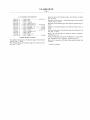
1
US006405549B1
(12)
United States Patent
(10) Patent N0.:
US 6,405,549 B1
(45) Date of Patent:
*Jun. 18, 2002
Baffes
(54)
PORTABLE HEATING UNIT USINGA
JP
REFRIGERANT CIRCUIT MOVABLE
WITHIN A ROOM
(73) Assignee: DO Enterprises, LLC, Chicago, IL
(Us)
Notice:
3/1987
OTHER PUBLICATIONS
(75) Inventor: Peter Ba?'es, Skokie, IL (US)
(*)
62056719 A *
Subject to any disclaimer, the term of this
patent is extended or adjusted under 35
U.S.C. 154(b) by 0 days.
OceanAire, Inc., Engineereing, Installation and Service
Manual, Aug. 1, 1998.
OceanAire, AirBoss advertising sheet, undated—admitted
prior art.
Heat Exchangers, Inc., Koldwave Engineering Installation
& Service Manual, undated—admitted prior art.
Air Rover, downloaded pages from internet website,
undated—admitted prior art.
(List continued on neXt page.)
This patent is subject to a terminal dis
claimer.
Primary Examiner—Chen-Wen Jiang
(74) Attorney, Agent, or Firm—Rockey, Milnamow &
KatZ,Ltd.
(57)
(21) Appl. No.: 09/708,981
Nov. 8, 2000
(22) Filed:
ABSTRACT
A portable heating and cooling unit intended to be used
Related US. Application Data
(63)
within a room or area of a building includes a cabinet
supported on a plurality of wheels and a refrigeration circuit
Continuation of application No. 09/497,956, ?led on Feb. 4,
2000, now Pat. No. 6,167,714, which is a continuation of
application No. 09/190,508, ?led on Nov. 12, 1998, now
abandoned.
at least partially carried within said cabinet. The refrigera
tion circuit includes a ?rst coil, a compressor, a second coil
and a refrigerant reversing valve. In a cooling mode of
operation, the ?rst coil acts as an evaporator coil and room
(51)
(52)
Int. Cl.7 .............................................. .. F25D 19/02
air is circulated by a ?rst fan across the evaporator coil and
US. Cl. ..................... .. 62/188; 62/324.1; 62/324.5;
delivered into the room. A second fan circulates room air
62/448
(58)
Field of Search ........................... .. 62/324.1, 324.5,
through the second coil acting as a condenser coil and
discharges the thus warmed air away from the room area to
62/323.1, 188, 288, 448, 196.4; 237/2 B
References Cited
(56)
U.S. PATENT DOCUMENTS
3,496,731 A
3,777,506 A
4,441,335 A
4,450,900 A
*
2/1970 Sholtes
12/1973 Hergatt et al.
4/1984 Bonne
5/1984 Nathan
(List continued on neXt page.)
be cooled. In a heating mode of operation, the refrigerant
reversing valve is activated to change the ?ow direction of
the refrigerant through the circuit such that the ?rst coil now
acts as a condenser and The second coil now acts as the
evaporator. Room air is drawn by the ?rst fan across the ?rst
coil to heat the room air and delivery the room air into the
area of the room to be heated. The second fan draws room
air through the evaporator coil and discharges the thus
cooled air away from the area of the room being cooled. The
refrigerant reversing valve is activated by a control which is
selectable to choose heating or cooling for the portable unit.
FOREIGN PATENT DOCUMENTS
EP
0718564 A2 *
6/1996
12 Claims, 3 Drawing Sheets
US 6,405,549 B1
Page 2
US. PATENT DOCUMENTS
4,745,770 A
*
4,888,958 A
5/1988 MintZ .................. .. 62/324.1 X
A
A
A
A
website, Sep. 2, 1998.
Koldwave, downloaded pages from Internet website, Sep. 2,
2/1990 Anthony
5,031,690 A
7/1991 Anderson et al.
5,065,584 A * 11/1991 BycZynski et al.
* 3/1992
* 2/1993
* 12/1993
* 7/1996
62/196.4 X
Takenaka et al. ........... .. 62/186
Matsumi .................... .. 62/262
Popelka et al.
....... .. 62/188
Voorhis ............... .. 62/324.5 X
5,729,985 A
5,762,129 A
5,794,452 A
3/1998 Yoshihara et al.
6/1998 Elliott
8/1998 Black et al.
6,167,714 B1 *
1/2001
Sep. 2, 1998.
Kornfort Industries, Inc., downloaded pages from Internet
12/1989 Ella
4,901,538 A
5,097,672
5,184,475
5,271,237
5,533,357
J ainsons Aircon, downloaded pages from Internet website,
Baffes ....................... .. 62/188
OTHER PUBLICATIONS
The Applied Companies, downloaded pages from Internet
website, Sep. 2, 1998.
1998.
Pinguino, downloaded pages from Internet website, Sep. 2,
1998.
Movincool Products, downloaded pages from Internet web
site, Sep. 2, 1998.
Ranco, pp. 28 through 35 technical manual, undated—
adrnitted prior art.
Parker, Installation Instructions for Model A Constant Pres
sure Expansion Valve, undated—adrnitted prior art.
Micro Air Corporation, FX—MaXX Operations Manual, Jan.
2, 1998.
The Avenger Series, downloaded pages from Internet web
site, Sep. 2, 1998.
* cited by examiner
U.S. Patent
Jun. 18,2002
US 6,405,549 B1
Sheet 1 0f 3
FIG.
I
lI?':d
I
In
U.S. Patent
Jun. 18,2002
Sheet 3 of3
FIG. 1+
US 6,405,549 B1
US 6,405,549 B1
1
2
PORTABLE HEATING UNIT USING A
REFRIGERANT CIRCUIT MOVABLE
WITHIN A ROOM
accessories to complete the refrigerant circuit. The ?rst coil
and the second coil can each alternately serve as evaporator
or condenser, depending on Whether the unit is being used
for heating or cooling. The cabinet also houses fans for
draWing room air into the cabinet to be heated or cooled by
the ?rst coil and returned to the room, and for draWing room
This is a continuation application of US. patent appli
cation Ser. No. 09/497,956, ?led Feb. 4, 2000 (now US. Pat.
No. 6,167,714), Which is a continuation application of US.
patent application Ser. No. 09/190,508, ?led Nov. 12, 1998
(noW abandoned), both of Which are entitled PORTABLE
COOLING AND HEATING UNIT USING REVERSIBLE
REFRIGERANT CIRCUIT.
air (heat exchange air) into the cabinet for causing either
evaporation or condensing of the refrigerant in the second
coil Wherein the thus cooled or Warm room air is ducted
10
aWay (or directed aWay) from the area being cooled or
heated.
The cabinet is mounted on caster Wheels to be portable
Within a building or other structure. The discharged heat
exchange air, either Warm air or cool air, can be ducted by
15
a ?exible duct to outside of the room being heated or cooled.
TECHNICAL FIELD OF THE INVENTION
The present invention relates to a portable heating and
cooling unit for use in localiZed and temporary cooling and
heating requirements in buildings, Warehouses, computer
In contrast to prior knoWn portable cooling units, the
rooms, and the like. Particularly, the present invention
relates. to a portable heating and cooling unit using a
refrigerant circuit, and Which is mounted in a cabinet sup
present invention includes a reversible refrigerant circuit for
ported on Wheels.
alternately cooling or heating room air. The refrigerant
circuit has a refrigerant ?oW reversing valve that can be
20
BACKGROUND OF THE INVENTION
Portable cooling units are knoWn Which are used in
localiZed cooling and heating applications in of?ce
25
buildings, Warehouses, computer rooms and the like. The
portable cooling units are held Within a cabinet Which in turn
is mounted on caster Wheels for mobility. The cooling unit
can be placed in near proximity to a particular location
Which is otherWise not adequately served by the central
cooling system of the building or other enclosure. The
portable cooling unit can be used to economiZe on cooling
supply in a large structure if only small areas need precise
cooling control or extra cooling capacity.
Portable cooling units are useful in localiZed cooling
second coil can be ducted aWay from the area served by a
for alternate heating or cooling periods.
One or more condensate drip pans are arranged beloW
35
40
45
second stream of room air is heated and the thus Warmed air
is directed aWay from the room area being cooled such as via
collection tank. A second drip pan for the second coil is
arranged at a position loWer than the condensate collection
tank. Acondensate pump is provided in the second drip pan
located beloW the second coil to pump condensate into the
condensate collection tank from the second drip pan.
shut off system Wherein, When the condensate level reaches
a maximum in the collection tank, the refrigeration circuit is
discharged simply in a direction aWay from the cabinet aWay
from the area to be cooled, or can be ducted to the central
shut doWn. The condensate collection tank can be drained
cooling system return air supply, or to outside of the
continuously by a hose connection to a room drain, or can
building.
be drained intermittently by manual drain, for example, by
55
removal of the condensate collection tank and draining of
the condensate collected therein. The ?rst coil Will typically
generate condensate during a cooling operation of the unit,
typically consists of an electric resistance coil Wherein a fan
circulates room air across the coil to heat the air and pass the
air back into the room.
SUMMARY OF THE INVENTION
into the room, has a ?rst drip pan Which is elevated from a
condensate collection tank, and any condensate collected in
The condensate collection tank can include an automatic
an exhaust duct. In some cases the Warmed air can be
rather than cooling capacity, is needed. The heating circuit
both the ?rst and second coils. Although a single drip pan
can be located beloW both coils, preferably one drip pan is
located beloW each coil. In accordance With the preferred
embodiment cabinet arrangement, the ?rst coil, Which serves
for alternately heating or cooling room air to be delivered
the ?rst drip pan drains by gravity into the condensate
room air across the condenser coil to condense the refrig
In some portable cooling units, an electric heating circuit
is provided for those occasions When extra heating capacity,
single duct for both alternate heating and cooling periods.
Neither the cabinet or the duct need be reversed or reducted
ing unit draWs a ?rst stream of room air past the evaporator
coil to cool the air, and passes the thus cooled air back into
the room. The cooling unit also draWs in a second stream of
erant therein. During condensing of the refrigerant, the
services from evaporator to condenser, or vice versa. By
reversing the services of the ?rst and second coils during a
sWitch from cooling to heating service, or vice versa, the ?rst
coil can alWays serve as the room air treating coil While the
second coil can alWays serve as the heat exchange air coil.
In this regard, the discharged heat exchange air from the
30
Within a room. The cooling units include a refrigeration
circuit Which typically includes an evaporator coil, a
compressor, a condenser coil and a pressure reducing or
expansion valve in a closed circuit containing Freon or other
suitable refrigerant. During cooling operation, such a cool
selectively sWitched to change the unit service from cooling
to heating, and the reverse. By reversing the refrigerant’s
?oW, the ?rst coil and the second coil effectively sWitch
While the second coil Will generate condensate during a
heating operation of the unit.
60
According to the invention, an electrical resistance heater
is no longer required for the alternate heating mode of the
portable heating and cooling unit. The portable heating and
The present invention contemplates a portable cooling
cooling unit can thus be ef?ciently operated as a cooler or a
and heating unit Which includes a reversible refrigerant
heater by manually reversing the refrigerant circuit. The
circuit to alternately provide either cool air or Warm air to a
portable heating and cooling unit is a compact and portable
room or area of a building. The portable unit includes a 65 apparatus Which effectively heats and cools localiZed areas
cabinet Which houses a refrigerant circuit including a ?rst
coil and a second coil, a compressor, and valving and
Within a building, Warehouse, computer room and the like.
It can be quickly changed in operation from cooling to
US 6,405,549 B1
3
4
heating by controls applied onto a front surface of the
cabinet. Condensate produced during either a heating or
cooling operation is effectively contained Within one or
the cabinet 22. The open end 42 of the duct Would be in
registry With the air outlet 38. Plenums, ducts, noZZles and
other air handling convenience items can also be added.
FIG. 3 illustrates in schematic fashion the components of
more drip pans, and stored in a condensate collection tank
for continuous or intermittent disposal.
Numerous other advantages and features of the present
invention Will become readily apparent from the folloWing
detailed description of the invention and the embodiments
thereof, from the claims and from the accompanying draW
10
mgs.
BRIEF DESCRIPTION OF THE DRAWINGS
in the refrigerant circuit, The refrigerant circuit is charged
FIG. 1 is a front perspective vieW of a portable heating
and cooling unit of the present invention;
15
FIG. 2 is a rear perspective vieW of the portable heating
With a refrigerant such as R22 refrigerant.
Air handling equipment includes a room air delivery fan
60 and a heat exchange air fan 62. The room air delivery fan
60 draWs air A1 through the air delivery inlet grille 27,
and cooling unit of FIG. 1;
FIG. 3 is a schematic layout of the portable heating and
cooling unit of the present invention, in a cooling mode of
across the ?rst coil 44 and through the air delivery outlet
grille 26 and into the room.
The exhaust fan 62 draWs air A2 through the heat
exchange air inlet grille 36, across the second coil 48, and
operation; and
FIG. 4 is a schematic layout of the portable heating and
cooling unit of the present invention, in a heating mode of
through the heat exchange outlet 38, through the duct 40 and
to a position outside of the room or at least aWay from the
air stream A1.
operation.
DETAILED DESCRIPTION OF THE
PREFERRED EMBODIMENTS
the heating and cooling unit 20 of the invention. FIG. 3
illustrates the unit 20 in a cooling mode of operation. A
refrigerant circuit includes a ?rst coil 44, a compressor 46,
a second coil 48, a bidirectional, ?xed ori?ce refrigerant
?oW control 50, and a refrigerant ?oW reversing valve 52. A
compressor accumulator 54, a bi-directional refrigerant
dryer 56, and a hot gas bypass regulator 58 are also included
25
In the cooling mode of operation, the refrigerant ?oW
circulates in the tubing as per the arroWs shoWn in FIG. 3.
The ?rst coil 44 serves as an evaporator coil, evaporating the
While this invention is susceptible of embodiment in
many different forms, there are shoWn in the draWings and
Will be described herein in detail speci?c embodiments
thereof With the understanding that the present disclosure is
to be considered as an exempli?cation of the principles of
26 and into the room.
The second coil 48 serves as a condenser coil, and air A2
the invention and is not intended to limit the invention to the
draWn through the second coil by the exhaust fan 62 is
refrigerant by removing heat from the room air A1 passing
across the coil 44 and thus cooling the room air Which passes
through the inlet grille 27 and out of the delivery outlet grille
speci?c embodiments illustrated.
FIGS. 1 and 2 illustrate a portable heating and cooling
heated as a refrigerant is condensed Within the coil 48.
35
unit 20 of the present invention. The unit includes a cabinet
22 mounted on four caster Wheels 24. The cabinet 22
includes a front panel 23, a rear panel 25, and tWo side
During this cooling operation, condensate may form on the
evaporator coil 44, and Within a chamber 68 Which is in
contact With the air A1, from moisture contained in the room
air. This condensate is collected in a ?rst condensate drip pan
70. A chamber drip de?ector 69 directs condensate to the
panels 35, 37. Either or both of the side panels 35, 37 are
?rst drip pan 70. Condensate from the coil 44 falls by gravity
removable to perform maintenance or service on the unit 20.
The cabinet includes a room delivery air outlet grille 26
into the pan 70. The drip pan 70 includes a gravity drain 72
angled upWardly on a front side of the cabinet. The unit also
includes a delivery air inlet grille 27 on a front side of the
and a drain line 74 Which feeds into a condensate collection
tank 76.
The condensate collection tank 76 can be designed for
cabinet. ApoWer cord 28 is provided for connecting the unit
to a source of electrical poWer. A condensate tank access 45
hand removal, through the access door 33 (shoWn in FIG. 2),
door 33 is provided on the side panel 35 of the cabinet.
for periodic draining, or can have a drainage hose connected
thereto for continuous draining. The collection tank 76
The unit includes a control 30 Which incorporates an
includes an automatic sWitch 77 Which deactivates the unit
20 When condensate level in the tank 76 is at a preselected
maximum condensate level. As an alternative, a condensate
pump can replace the tank 76, the condensate pump receiv
electronic thermostat 34 and associated displays and select
able controls. The control 30 can be, for example, a MICRO
AIR, Model FX Maxx controller, supplied by Micro Air
Corporation of AllentoWn, N]. This control alloWs for both
automatic and manual operation of both refrigeration cir
ing condensate from the drip pan 70 and pumping the
cuits and fan equipment. The control can provide for auto
condensate to a discharge location at a distance from the unit
matic sWitching betWeen cooling and heating modes. Room
20. The compressor 46 is then shut off, shutting doWn the
refrigerant circuit. The fans 60, 62 can be shut doWn also.
During a heating operation as shoWn in FIG. 4, the ?rst
temperature and moisture can be monitored and the unit
55
operated accordingly.
On a back side of the cabinet 22 is a heat exchange air
coil 44 serves as a condenser, and the second coil 48 serves
inlet grille 36 for draWing heat exchange air into the cabinet
as the evaporator. The How of refrigerant is reversed by
operation of the refrigerant ?oW reversing valve 52. Air A1
passing through the ?rst coil 44 is heated, and thus Warm air
22. A heat exchange air outlet 38 is located on a top side of
the cabinet and can be connected to a ?exible duct 40 for
exhausting heat exchange air to a position outside of the
is delivered to the room from the delivery outlet grille 26.
room being heated or cooled. The duct 40 can be connected
Air A2 passing through the second coil 48 is cooled,
delivering cool air out of the heat exchange air outlet 38 and
to an air-to-outside vent through a Wall or WindoW, or
through the duct 40 aWay from the air stream A1.
connected to a return air duct 39 of the building central
heating and cooling system, typically an overhead duct as
shoWn in FIG. 3. A plate or plenum 41 restraining an open
end 42 of the duct 40 can be fastened to a top panel 43 of
65
The reversal of the refrigerant reversing valve 52 is
actuated by the control 30 either manually, or automatically
based on room temperature. The reversing valve itself can
US 6,405,549 B1
6
5
be, for example, a RAN CO reversing valve (3-Way or 4-Way
second coil, and a reversing means, Wherein said
pilot design) With a Ranco L-27 or L-30 solenoid coil.
reversing means alternatively sWitches the operation of
said ?rst coil and said second coil betWeen an evapo
rator coil and a condenser coil; and
a ?rst fan and a second fan, said ?rst fan for passing a ?rst
room air stream across said ?rst coil and returning the
?rst room air stream to the room, and said second fan
It is possible that during heating mode of operation,
especially When the unit is operated in a cold environment,
that the temperature of the air A2 passing across the evapo
rator coil 48 is loWered to such an extent that condensed
Water vapor on the evaporator coil 48 is frozen on the coil.
for passing a second room air stream across that second
This reduces the overall efficiency of the unit by decreasing
the heat transfer coefficient of the coil. To alleviate this
problem, a controlled amount of hot gas can be bypassed by
the hot gas bypass regulator 58 from the compressor 46 into
coil and delivering the second room air stream aWay
10
from the room.
2. The portable heating unit according to claim 1, Wherein
said second fan is How connected to an air outlet, and further
comprising a duct connected to said air outlet at one end and
an inlet of the evaporator coil 48, to prevent frosting by
excessively loW evaporator temperatures The hot gas bypass
regulator can be a refrigerant pressure controlled valve, such
connected to a space outside of the room at an opposite end
thereof.
as a PARKER Model A constant pressure expansion valve, 15
supplied by Parker Hanni?n Corporation of LongWood, Fla.
This valve is normally spring-loaded closed. HoWever, the
3. The portable heating unit according to claim 1, Wherein
said cabinet is supported on a plurality of caster Wheels for
rolling transport of said portable heating unit.
4. The portable heating unit according to claim 1, further
spring is so arranged that if the outlet pressure of the valve
drops beloW a preset pressure the valve Will open. The
comprising a condensate collection pan arranged beneath at
regulator Will, for example, maintain the R22 refrigerant
least one of said ?rst and second coils.
pressure at 60 psig doWnstream of the regulator, entering the
5. The portable heating unit according to claim 1, further
second coil 48.
This Will maintain the evaporator at a suf?ciently high
temperature to avoid frosting on an outside of the second
coil 48.
comprising a ?rst condensate collection pan arranged
beneath said ?rst coil, and a second condensate collection
pan arranged beneath said second coil.
25
An alternate hot gas bypass system for defrosting Which
can be incorporated into the present refrigerant circuit is that
disclosed in Us. Pat. No. 5,794,452, herein incorporated by
reference. In this patent hot gas from the compressor is
periodically bypassed through a hot gas valve (16) to the
system evaporators to remove ice (the “harvest” cycle for an
ice maker). A harvest bypass valve (14) can be used to
introduce an additional quantity of refrigerant into the
compressor to insure suf?cient refrigerant to carry out the
harvest cycle Within a predetermined time period. Aperiodic
6. The portable heating unit according to claim 5, further
comprising a condensate collection tank, and also further
comprising a condensate pump having an inlet in How
communication With one of said ?rst and second condensate
collection pans and an outlet in How communication With
said condensate collection tank.
7. The portable heating unit according to claim 6, Wherein
35
said condensate collection tank includes an automatic refrig
eration circuit shutoff Which activates on high condensate
level Within said condensate collection tank to stop opera
tion of said compressor.
8. The portable heating unit according to claim 1, Wherein
defrosting such as disclosed in Us. Pat. No. 5,794,452 can
also be incorporated in the present invention as Well.
upWardly angled air delivery outlet above said air inlet, and
During the heating mode, With the second coil 48 serving
said ?rst coil is arranged behind said air inlet, said ?rst fan
as the evaporator, condensate can form on the second coil 48
draWing air through said air inlet, through said ?rst coil, and
and drip into a second drip pan 90. In the preferred compact
out of said angled air delivery outlet and into the room being
arrangement of the cabinet 22, the second coil 48 is at a
loWer elevation than the condensate collection tank. Thus, a
small pump 94 is provided in the condensate drip pan 90 to
deliver the collected condensate via a tube 97 to the collec
heated [or cooled].
tion tank. The condensate pump 94 can be controlled for on
and off operation depending on the condensate level col
lected Within the second drip pan 90 by a ?oat sWitch 98.
Although separate ?rst and second drip pans 70, 90 are
shoWn, a single drip pan could be arranged beloW both coils
44, 48. Also, the coil 48 could also be elevated above the
condensate tank such that the second drip pan 90 could
includes a gravity drain to the condensate collection tank,
thus eliminating the condensate pump 94.
From the foregoing, it Will be observed that numerous
variations and modi?cations may be effected Without depart
ing from the spirit and scope of the invention. It is to be
understood that no limitation With respect to the speci?c
apparatus illustrated herein is intended or should be inferred.
It is, of course, intended to cover by the appended claims all
said cabinet includes a front side delivery air inlet and an
9. The portable heating unit according to claim 1, Wherein
said refrigeration circuit comprises a hot gas bypass regu
45
regulator valve alloWing a controlled amount of refrigerant
gas from said compressor to enter said evaporator coil.
10. Aportable heating unit for positioning inside a room
of a building, comprising:
a cabinet mounted on a plurality of Wheels;
a refrigeration circuit carried at least partially Within said
cabinet, and said refrigeration circuit including a ?rst
coil, a compressor, a second coil, a reversing means,
55
fan for passing room air across said second coil,
said cabinet including an air delivery inlet in registry With
said ?rst coil and an air delivery outlet receiving air
from said ?rst fan and communicating the air into the
room, and having a heat exchange air inlet on a
prising:
a refrigeration circuit carried Within said cabinet, said
circuit including a ?rst coil, a refrigerant compressor, a
Wherein said reversing means alternatively sWitches the
operation of said ?rst coil and said second coil betWeen
an evaporator coil and a condenser coil, and a ?rst fan
for passing room air across said ?rst coil and a second
such modi?cations as fall Within the scope of the claims.
The invention claimed is:
1. A portable heating unit movable Within a room, com
a cabinet siZed to be movable Within a room;
lator valve in How communication With an outlet of said
compressor and With an inlet of said evaporator coil, said
65
backside of the cabinet in registry With the second coil
and a heat exchange air outlet in How communication
With the second fan for delivering heat exchange air out
of the cabinet.
US 6,405,549 B1
7
8
11. Aportable heating unit according to claim 10, further
comprising a condensate drip pan arranged beneath said
and a condensate pump having an inlet in How communi
cation With said drip pan and an outlet in How communica
tion With said condensate tank.
second coil.
12. Aportable heating unit according to claim 11, further
comprising a condensate tank mounted Within said cabinet