1
Corporation
1260
User's
Guide
500250 Rev. K
Copyright Notice
Information contained in this document is copyrighted by Qualstar Corporation. It is
intended for use by Qualstar's customers and prospective customers to evaluate, integrate, operate and maintain Qualstar products. Customers and prospective customers
may reproduce this document as needed for these uses. Reproduction in whole or in
part for any other use or by any other party is prohibited without prior written permission from Qualstar Corporation.
Every effort has been made to keep the information contained in this document current and accurate as of the date of publication or revision. However, no guarantee is
given or implied that the document is error-free or that it is accurate with regard to
any specification. Qualstar reserves the right to modify product designs and specifications without notice.
• Qualstar® is a registered trademark of Qualstar Corporation.
• Cipher® is a registered trademark of Archive Corporation.
• Pertec® is a registered trademark ofDDC Pertec ..
• IB~ is a registered trademark of International Business Machines, Incorporated.
Caution!
References contained in this manual to DIP switch settings, jumper locations, primary voltages and other options are for reference only. Access
to the interior of this equipment is restricted to dealers and qualified
service technicians, and only in accordance with published service manuals and bulletins.
For service information or help with installation,
please write or call Qualstar Customer Support:
Qualstar Corporation
6709 Independence Avenue
Canoga Park, CA 91303
FAX: (818) 592-0116
Phone: (818) 592-0061
ii
500250K
Important - Read This Before Opening the Package
Qualstar Corporation has made every effort to provide quality merchandise. If the
merchandise arrives damaged or has been mishandled, please notify the delivery company immediately. If the merchandise is defective in any other way, please follow
these instructions.
If this merchandise was purchased from a dealer or other reseller, contact that dealer
or reseller for return instructions.
If this merchandise was purchased directly from Qualstar, please do the following:
• Treat the merchandise carefully to assure its suitability for return.
• Retain all shipping and packing materials. Returned merchandise must be
shipped to Qualstar in the original packing material and carton. If the original
packing material or carton has been damaged, a new set may be requested.
• Call Qualstar Customer Service at (818) 592-0061 to request a Return Merchandise Authorization (RMA) number. Returned merchandise will not be accepted without this number.
• Clearly identify the outside of the carton and the packing list with the RMA number.
• Return the merchandise, including cables, manuals, software and all related documents to:
QUALSTAR CORPORATION
6709 Independence Avenue
Canoga Park, CA 91303
Attn: Customer Service
FAX: (818) 592-0116
Phone: (818) 592-0061
Federal Communications Commission Requirements
This equipment has been tested and found to comply with the limits for a Class A computing device pursuant to Subpart J of Part 15 of FCC Rules, which are designed to
provide reasonable protection against such interference when operated in a commercial environment. Operation of this equipment in a residential area may cause unacceptable interference to radio and TV reception, in which case the user at his own
expense will be required to take whatever steps are necessary to correct the interference.
500250 K
iii
Limited Warranty
QUALSTAR SHALL NOT BE RESPONSIBLE OR LIABLE FOR AA"Y SPECIAL, INCIDENTAL OR CONSEQUENTIAL DAMAGES OR LOSS L~~ISING FROM THE
USE OF THIS PRODUCT.
THIS WARRANTY IS IN LIEU OF, AND BUYER WAIVES, ALL OTHER WARRANTIES, EXPRESSED OR IMPLIED, ARISING BY LAW OR OTHERWISE, INCLUDING WITHOUT LIMITATION ANY IMPLIED WARRANTY OF
MERCHANTABILITY OR FITNESS FOR A PARTICULAR PURPOSE. THE REMEDIES STATED IN THIS WARRANTY ARE EXCLUSIVE.
Qualstar Corporation warrants this Magnetic Tape Transport or Tape Subsystem to
be free from defects in materials and workmanship under normal use and service for a
period of one year from the date of shipment from the factory to the buyer, provided
however that goods or parts which are replaced or repaired under this warranty are
warranted only for the remaining unexpired portion of the original warranty period
applicable to the goods in which they are installed. This warranty does not apply to accessories such as tape, carrying cases, or manuals.
Qualstar's sole and exclusive obligation under this limited warranty is to repair or replace at Qualstar's option all products that are returned to Qualstar within the applicable warranty period and found by Qualstar to be defective. Replacement parts may
be either new or reconditioned at Qualstar's option. The Buyer is responsible for properly packing the unit to be returned in accordance with applicable user's guide instructions, and the Buyer shall ship the unit prepaid at Buyer's expense. Qualstar will return
the unit to the Buyer prepaid at Qualstar's expense via surface transportation. Air transportation, customs charges, and other special charges are the responsibility of the Buyer.
This warranty shall immediately be null and void if, in Qualstar's sole judgement, the
unit has been altered or repaired other than with authorization from Qualstar and by
its approved procedures, has been subject to misuse, abuse, negligence or accident,
damaged by excessive voltage, damaged in shipment, subjected to improper environmental conditions or had its serial numbers and/or other product markings altered, defaced or removed. Normal user preventive maintenance such as tape path cleaning as
set forth in Qualstar's User's Guides is the responsibility of the Buyer and is excluded
from this warranty.
This warranty will remain in effect notwithstanding Buyer's shipment to third parties, but warranty remedies defined herein are applicable only to Buyer and are not
transferable. Buyer shall disclose to third parties the terms of this warranty and shall
indemnify Qualstar from any failure to make such disclosure and from any warranties
made by the Buyer beyond those set forth herein.
Qualstar makes no representations as to the suitability of Software supplied for use in
any application, and the Buyer agrees to accept all such Software on an "as is" basis.
Furthermore, Qualstar does not warrant Software to be free from defects, and assumes no
responsibility for damages of any kind, either actual or consequential, for such Software failing to perform as documented or in any other manner. In no event will Qualstar be liable for damages, including any lost profits, lost savings or other incidental
iv
500250 K
or consequential damages arising out of the use or inability to use such software, even
if Qualstar has been advised of the possibility of such damages, or for any claim by
any other party.
Qualstar Service Policy
Service is provided at the Qualstar factory in Canoga Park, California, USA. Additionally, service may be available on site or in selected locations from a Qualstar factoryauthorized service organization. Consult a Qualstar sales representative for further
information.
All material returned to the Qualstar factory for any reason must be authorized prior
to shipment. Write or Call Qualstar Customer Service to obtain an RMA number. This
number must appear on all boxes and packing slips. Qualstar will refuse delivery ofmaterial without proper RMA identification.
Units being returned must be shipped in the original packing material and shipping
carton. Any damage or expenses resulting from shipping in a non-authorized shipping
carton will be the responsibility of the Buyer. If the original carton and packing are
not available, they may be purchased from Qualstar.
In-Warranty Service
If this merchandise was purchased from a dealer/reseller, consult that dealer/reseller
for instructions. Qualstar's warranty obligation is to the original purchaser (dealer/reseller) only.
If this merchandise was purchased directly from Qualstar, in-warranty service will be
provided at the Qualstar factory in Canoga Park, California, USA. The Buyer is responsible for all freight charges incurred in returning the merchandise to the factory.
Qualstar will return the merchandise to the Buyer prepaid at Qualstar's expense by
surface transportation. The expense of air transportation, if requested, is the responsibility of the buyer.
In-warranty service may also be available on-site or at selected Qualstar factoryauthorized service centers for an additional charge. Consult a Qualstar sales representative for further information.
Out-Of-Warranty Service
Should service be required after the warranty period has expired, Qualstar will repair
and test the tape drive or tape subsystem for a flat fee as shown in the current price
list. Service charges, freight and customs charges will be billed to the Buyer.
An Extended Service Agreement, available for units located within the United States,
may be purchased which extends the warranty period for one year. Units covered under the Extended Service Agreement may be serviced as often as required during the
contract period. Prices are shown in the Factory Service Price List and include return
freight by surface transportation. Qualstar customer service representatives can provide details on the Extended Service Agreement.
500250 K
v
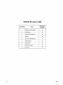
500250 Revision Table
CHAPTER
REVISION
LETTER
TITLE
Title Page and Contents
K
1
Installation
K
2
Controls and Operation
K
Options
K
Preventive Maintenance
K
3
I
4
!
5
ISpecifications
6
Error Codes
I
K
!
I
I
I
I
I
i
K
I
r
7
I
vi
8
ISCSI Information
AC Power
K
!
I
K
500250 K
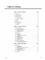
Table of Contents
Chapter 1. Tape Drive Installation
1.1. Introduction
1-1
1.2. Model Identification
1-2
1.3. Operating Environment
1-2
1-2
1.4. Power Requirements
.
1.4.1. Power Connections .
. 1-2
1.5. Tools Required for Installation
1-3
1.6. Unpacking
1-3
1.7. Orientation
1-3
1.8. Interface Connections
1-4
1.8.1. Model 1260 .
1.8.2. 1260B .
1.8.3. 12605 . . . .
Chapter 2. Controls and Operation
2.1. Controls and Indicators
2.1.1.
2.1.2.
2.1.3.
2.1.4.
2.1.5.
LOAD Switch and Indicator
ONLINE Switch and Indicator
FPT Switch and Indicator .
6250 Switch and Indicator.
Power Switch
2.2 . Tape Operation
2.2.1.
2.2.2.
2.2.3.
2.2.4.
2.2.5.
2.2.6.
2.2.7.
2.2.8.
Applying Power .
Loading a Tape .
Loading with Tape Already Threaded
Loading Near EOT . . . .
Unloading a Tape . . . .
File-Protecting the Drive .
Changing Data Densities.
Aborting Runaways . . .
2.3. Using the Demonstration Mode .
2.3.1. Activating the Demonstration Mode
2.3.2. Deactivating the Demonstration Mode.
Chapter 3. Field Selectable Options
3.1. Option Switches
3.1.1.
3.1.2.
3.1.3.
3.1.4.
3.1.5.
3.1.6.
3.1 .7.
Diagnostic Enable (Sl) .
Enable ICER (52) . . . . . .
IDBY during Filemark Search Commands (S3)
Filemark Gap Length (54) . . . .
Extended Write Gaps (S5 and 56)
Default Density (57) . . . . . . .
Automatic Density Select (58)
3.2. Option Jumpers
500250 K
Page
1-4
1-5
1-5
Page
2-1
2-1
2-1
2-1
2-1
2-2
2-2
2-2
2-2
2-3
2-3
2-4
2-4
2-4
2-4
2-4
2-5
. 2-5
Page
3-1
3-1
3-1
3-1
3-2
3-2
3-3
3-3
3-4
vii
3.2.1.
3.2.2.
3.2.3.
3.2.4.
3.2.5.
3.2.6.
3-4
3-4
3-4
3-5
3-5
3-5
Formatter Address (WO - W7) . . . . . . . . . . . . . . . . . . . . . . . . . .
Formatter Enable (WS) . . . . . . . . . . . . . . . . . . . . . . . . . . . . .
Status Control Signals (W9) . . . . . . . . . . . . . . . . ..
. ...... .
W10, W11, W12 . . . . . . . . . . . . . . . . . . . . . . .
IFEN Abort (W13) . . . . . . . . . . . . . . . . . . . . . . . . . . . . .
. .............. .
Read/Formatter Wl . . . . . . .
Chapter 4. Preventive Maintenance
4.1. Preventive Maintenance Schedule
Page
4-1
.
4.1.1. Why Preventive Maintenance Is Necessary
4.1.2. Frequency of Preventive Maintenance
. 4-1
. . . 4-2
4-2
4.2. Tape Path Cleaning Procedure
Page
Chapter 5. Specifications
5-1
5.1. Data Specifications
5.1.1. Data Formats . . . .
5.1.2. Data Transfer Rate . . . . . . . . . . . . . . . .
5.1.3. Media Requirements
5-1
. . . . . . . 5-1
. . . . . 5-1
5-1
5.2. Data Capacities
5.2.1.
5.2.2.
5.2.3.
5.2.4.
5.2.5.
5.2.6.
5.2.7.
5.2.S.
5.2.9.
Tape Length . . . . . . . .
. . . . . .
. ........ .
Recording Density . . . . .
. . . . . . . .
. ........ .
IBG Length . . . . . . . ..
. .............. .
Block Length . . . . . . . . . . . . . . . . . . . . . . . . . .
. ......
Number of Filemarks . . . . . . . . . . . . . . . . . . . . . .
Data Capacity, Unformatted . . . . . . . . . . . . . . . . . . . . . . . . . .
Data Capacity, Formatted at 1600 cpi . . . . . . . . . . . . . . . . . .
Data Capacity, Formatted at 3200 cpi
Data Capacity, Formatted at 6250 Cpi . . . . . . . . . . . . . . . . . . . . . . . . . .
Chapter 6. Error Codes and Operational Failures
Page
6.1. Load Fault
6-1
6.2. File Protect Fault
6-1
6.3. Read After Write Fault
6-2
6.4. Start/Position Fault .
6-2
6.5. Write/Erase Power On Fault
6-2
6.6. Write/Erase Power Fail Fault
6-2
6.7. Motion Fault
6-2
6.8. BOT Fault
6-3
6.9. 1260S Error Indications
6-3
Chapter 7. Supplemental SCSI Drive Information
7.1. Changing the SCSI ID.
Page
.
7-1
7.2. Model Identification
7-2
7.3. Model 1260S Description
7-2
7.3.1.
7.3.2.
7.3.3.
7.3.4.
7.3.5.
7.3.6.
viii
5-2
5-2
5-2
5-2
5-2
5-3
5-3
5-4
5-4
General . . . . . . . . . . . .
SCSI Power-Up Self Test .. .
Single-Ended Configuration ..
On-Board Buffer .
Long Blocks . . . .
. ................................
SCSI Configuration
7-2
7-3
7-3
7-3
7-4
7-4
500250 K
7.4. Differences between SCSI and the Pertec Interface
7-4
7.5. SCSI Bus Description
7-5
.
7.6. Cables and Connectors
7-5
7.7. SCSI Bus Termination .
7-6
7.7.1. Internal Terminators .
7.7.2. External Terminators.
7.7.3. Termination Power ..
7-6
· 7-6
· 7-7
7.B. Switches, LEOs, and Jumpers
7.8.1.
7.8.2.
7.8.3.
7.8.4.
7.8.5.
7-B
SwitchbankS1 . . . . . .
Pushbutton S2 . . . . . . .
Display Indicators DS7 through DSO .
Switchbank S3 . . . .
Jumpers . . . . . . . . . . . .
7.9. Resetting the SCSI PCBA
7-11
.
7.10. SCSI PCBA Configuration Modes
7.10.1.
7.10.2.
7.10.3.
7.10.4.
7.10.5.
7.10.6.
7.10.7.
7.10.8.
7.10.9.
Mode 0 - Normal Operating Mode . .
Mode 1 - View Configuration Data ..
Mode 2 - Alter Configuration Data ..
Mode 3 - Reload RAM from EEPROM
Mode 4 - Save Configuration .. .
Mode 5 - Factory Default . . . . .
Mode 6 through Mode 0 - NoOp
ModeE-FactoryTest . . . .
Mode F - Continuous Self-Test
7.11. Changing SCSI Parameters
.
7.12. SCSI Configuration Parameters
7.12.1. SCSI Device 10 (Address 00)
7.12.2. SCSI Parity (Address 01) .
7.12.3. SCSI Sync (Address 02) ..
7.12.4. Space Write (Address 03) .
7.12.5. Write EOT (Address 04) .
7.12.6. Write Retries (Address 05)
7.12.7. Address 06 . . . . . . . .
7.12.8. Buffer Switch (Address 07)
7.12.9. Early EOT (Address 08) ..
7.12.10. EOM On Read (Address 09) .
7.12.11. Set Inquiry Data (Address OA) .
7.12.12. Lng Blk (Address OB) . . . .
7.12.13. AddressOC-OD . . . . . .
7.12.14. Read Bad Data (Address 0) .
7.12.15. Read EOT Stop (Address OF)
7.12.16. Read Ahead (Address 10) .
7.12.17. Read CER (Address 11) ..
7.12.18. Read Retries (Address 12) .
7.12.19. Residue (Address 13) .
7.12.20. Unload (Address 14) . . .
7.12.21. SCSI LUN (Address 15) ..
7.12.22. Rewrite CER (Address 16) .
7.12.23. Write CER (Address 17)
7.12.24. Busy (Address 18) . . . . .
7.12.25. Read HER (Address 19) ..
7.12.26. Write HER (Address 1A) ..
7.12.27. Block Length (Address 1B) ..
7.12.28. Address 1C - AF . . . . . . .
7.12.29. Inquiry Data File (Address BO - F5)
7.12.30. Address F6 - FD . . . . . . . . . .
7.12.31. Drive Model Number (Address FE)
500250 K
7-8
· 7-8
· 7-9
7-10
7-11
7-11
7-12
7-12
7-13
7-13
7-14
7-14
7-15
7-15
7-15
7-15
7-16
7-17
7-17
7-19
7-19
7-19
7-20
7-20
7-20
7-21
7-21
7-21
7-25
7-25
7-26
7-26
7-26
7-26
7-27
7-27
7-27
7-28
7-28
7-28
7-29
7-29
7-30
7-30
7-30
7-30
7-30
7-30
ix
7.12.32. Checksum (Address FF) . . . . . . . . . . . . . . . . . . .
7-31
7.13. Drive Configuration Requirements
7.13.1.
7.13.2.
7.13.3.
7.13.4.
7.13.5.
Formatter Address (WO - W7) . . . . . . . . . . . . . . . . . . . . . . . . . . .
IFEN (W8) . . . . . . . . . . . . . . . . . . . . . . . . . . . . . . . . . . . . .
Status Control Signals (W9) . . . . . . . . . . . . . . . . . . . . . . . . . . . .
IFEN Abort (W13) . . . . . . . . . . . . . . . . . . . . . . . . . . . . . . .
Read/Formatter PCBA W1 . . . . . . . . . . . . . . . . . . . . . . . . . . . . .
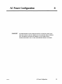
Chapter 8. AC Power Configuration
x
7-31
.
.
.
.
7-31
7-31
7-31
7-31
7-31
Page
8.1. Tools Required to Change AC Power Configuration
8-2
8.2. Opening the Drive
8-2
8.3. Closing the Drive
8-2
8.4. Configuring the Drive for Available Power
8-2
500250 K
Tape Drive Installation
1.1
1
Introduction
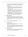
This guide provides installation instructions and techniques for operating the Qualstar 1260 series tape drives. In order for the tape drive to operate, it must be connected to a tape coupler card within your computer. Refer to the specific coupler
manual for the installation and configuration of the tape coupler before installing
your tape drive.
The software provided with the coupler controls the transfer of data to and from the
tape drive. The wide variety of options which Qualstar offers allows the tape drive to
operate with a number of different coupler packages. The best choice of couplers depends upon your particular application and computer system.
Figure 1-1
The Qualstar 1260 Series Tape Drive
500250 K
Tape Drive Installation
1-1
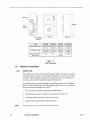
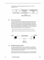
1.2
Modelldentification
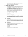
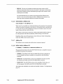
Figure 1-2 shows the breakdown of the 1260 Series model numbers. This guide applies to all models. The basic tape drive in each of the models covered by this guide is
the same. Differences among models is noted when required. From an operator's point
of view, all models function similarly.
BASIC SERIES
SPECIAL CONFIGURATION
1 2 6 0 X
B = 256K Buffer
E = Extended Chassis
S = SCSI Device
Figure 1-2
Model Number Identification
1 .3
Operating Environment
The tape drive is designed to operate in an environment between 40 F to 104 F (4.4
C to 40 C), 20% to 85% relative humidity, and at altitudes from 0 to +8000 feet. Moisture must not be allowed to condense inside the drive or in the tape path area. Note
that the humidity specification of the drive exceeds that of the media.
0
0
0
0
1 .4
Power Requirements
The tape drive requires 100, 120,220, or 240 volts AC, +10%/-15%, at 48 to 62 Hertz
primary power. Peak power requirements for model 1260 is 195 watts, and 211 watts
for models 1260B and 1260S.
DANGER!
1.4.1
IF THE LINE VOLTAGE DIFFERS FROM THAT SPECIFIED ON THE NAMEPLATE, DO NOT APPLY POWER. THE POWER TRANSFORMER TAPS INSIDE
THE DRIVE AND THE FUSE MUST FIRST BE CHANGED BY A QUALIFIED
SERVICE PERSON TO MATCH THE LINE VOLTAGE. REFER TO CHAPTER 8.
Power Connections
The power connection to the drive is by means of a detachable power cord which complies with the following specifications.
• 100/120 volt applications - U.L.listed and CSA certified three conductor, 18
AWG, SVT vinyl jacketed cord. One end is terminated with an lEC 320, C13
style connector (CEE-22 standard sheet VI). The remaining end is terminated
with plug type NEMA 5-15P.
1-2
Tape Drive Installation
500250 K
• 220/240 volt applications - D.L.listed and CSA certified three conductor, 18
AWG, SVT vinyl jacketed cord. One end is terminated with an IEC 320, C13
style connector (CEE-22 standard sheet VI). The other end is not terminated.
The conductors are to be connected to a customer-supplied plug as follows:
Black or brown wire to AC hot (Live); white or blue wire to AC return (neutral
or common); green or green with yellow strips to chassis (ground).
The following statement is included for compliance with German safety regulations:
Die Verbindung ziir Steckdose sollte moglich kurz sein, und die Steckdose sollte frei
zuganglich bleiben.
(English translation: The connection to the power receptacle should be as short as possible, and the receptacle should be readily accessible.)
1.5
Tools Required for Installation
A #2 Phillips screwdriver is required to install the drive.
1.6
Caution!
Unpacking
Model 1260 tape drives weigh between 36 and 44 pounds, depending
upon the configuration. Use caution in lifting.
The tape drive is shipped in a specially designed double-walled carton with energyabsorbing end caps. The packaging should be stored for possible future transportation
purposes.
The carton contains the following items:
• Tape Drive
• Power Cord
• User's Guide
• Interface Cable(s) (optional)
Remove the drive together with its end-caps from the carton and place it on a table.
Then remove the end-caps and the polyethylene bag.
Remove all other materials from the carton and store the end-caps and bag in the carton for the possibility of future shipment.
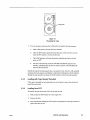
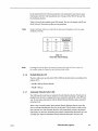
1 .7
Orientation
The drive must be placed on a hard surface; do not place it on a typewriter pad or similar surface. It may rest on its bottom, back or side. There must be no obstructions
which would prevent air from freely flowing into the fan inlet(s) or exiting from the
ventilation slots.
500250 K
Tape Drive Installation
1-3
Fanlnleffi
Power
Switch
UW
~nT
'\~
~
I
I
I
1
I
HEIGHT
o
roolU
~II
WIDTH
AC Plug and
II~~
- I DEPTH 1-
-I
Fuseholder
1260
WIDTH
HEIGHT
DEPTH
WEIGHT
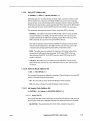
Without Door Option
12.25 inches 21.50 inches 8.25 inches
(54.6 cm)
(31.1 cm)
(20.9 cm)
38 pounds
(17.2 kg)
With Door Option
12.75 inches 21.50 inches 9.25 inches
(32.4 cm)
(54.6 em)
(23.5 cm)
44 pounds
(19.9 kg)
Additional for SCSI or
buffer option
none
none
1 inch
(2.5 cm)
2 pounds
Figure 1-3
1260 Dimensions
1.8
1.8.1
Interface Connections
Model 1260
Model 1260 uses the Pertec interface which consists of either two cables with a 50-pin
card edge connector on each, or a single cable branching out into two 50-pin card edge
connectors. The card edge connectors must be connected to Jl and J2 (sometimes referred to as JI0l and JI02 respectively) inside of the tape drive.
A removable cable entry cover is attached to the side chassis panel with two Phillips
screws. A round interface cable can be fed through the slot in the cover. A decal shows
the correct connector orientation of Jl and J2.
Note:
1-4
1.
Turn the tape drive offbefore attaching the interface cables.
2.
With the drive resting on its rubber feet, remove the cable entry cover.
3.
Connect the cables to Jl and J2 as shown on the decal.
4.
Dress the cables and reinstall the cable entry cover.
The cable entry cover must be in place to meet FCC requirements.
Tape Drive Installation
500250 K
1.8.2
12608
This model contains a Buffer PCBA. Refer to the Buffered Interface Supplement (document 500200) for instructions.
1.8.3
1260S
This model connects to a SCSI bus. Refer to Chapter 7 for further information.
500250 K
Tape Drive Installation
1-5
2
Controls and Operation
2.1
2.1.1
Controls and Indicators
LOAD Switch and Indicator
Use the LOAD switch to load, rewind and unload tapes.
The LOAD indicator is illuminated when the tape is at Beginning of Tape (BOT.)
\Vhen the tape is unloaded (no tension,) the LOAD indicator will flash rapidly when a
BOT marker is sensed, providing a means of testing the BOT sensing circuits.
2.1.2
ONLINE Switch and Indicator
Use the ONLINE switch to place the drive online and offline. The drive will only respond to the host ifit is online. You may place the drive online whenever tape is
loaded and tensioned and may take the drive offline at any time.
Pressing the switch while a command or rewind operation is in progress will abort the
command and place the drive offline. All tape motion, except for rewind, will halt. You
can also use this switch to take the drive offline to abort a runaway operation.
When the Online indicator is illuminated, the drive is online and ready for operation.
When it is not illuminated, the drive is offline and will not accept any commands from
the host.
2.1.3
FPT Switch and Indicator
If the drive detects the presence of a write enable ring on the bottom side of the supply
reel, the drive will initially be write-enabled. You can override this condition and
manually protect the tape by pressing the FPT switch while the LOAD indicator is illuminated and the tape is at BOT. The FPT switch has no effect when no write ring is
present.
When the drive is write-enabled, it can write on and erase tape. When the drive is fileprotected, its write and erase circuits are disabled. The FPT indicator will be illuminated when the drive is in the file-protected state, and will not be illuminated when
the drive is in the write-enabled state.
The FPT indicator serves as a power indicator when a tape is not tensioned.
When the tape is threaded but not tensioned, the FPT indicator will flash rapidly
when an End-Of-Tape (EOT) marker is sensed, providing a means of testing the EOT
sensing circuits.
2.1.4
6250 Switch and Indicator
When the tape is unloaded, or when it is tensioned and at BOT and the drive is offline, you can select an operating density of either 6250 characters per inch (cpi) or
500250 K
Controls and Operation
2-1
1600 cpi by pressing the switch. When the drive is online and the tape is tensioned
and at BOT, the host may also select either density.
The data density for both writing and reading is indicated by the 6250 indicator.
When illuminated, the drive reads and writes at 6250 cpi and when extinguished, at
1600 cpi.
Either 1600 or 6250 cpi may be selected for a default density upon power-up according
to an option switch setting. This should not be confused with Automatic Density Select, which is determined after the first read operation. Refer to Chapter 3 for more information.
2.1.5
Power Switch
The POWER switch is located on the side of the drive near the AC line receptacle.
2.2
2.2.1
Tape Operation
Applying Power
Caution!
It is possible to create an undesired flux transition on a tape if the tape is
touching the head when power is applied. This is not normally a problem, since the tape is not generally loaded when power is applied. If the
tape is threaded past the BOT tab, make certain that there is at least 1/8
inch gap between the tape and the head before applying power.
Press the side of the switch with the "I" to apply power. Listen for the fans. If they do
not operate, the drive is not operational. Turn the power off, verify the power source
and then turn the drive back on again. If this fails, the drive will require service. After
a normal power-up sequence, the FPT indicator should be illuminated. The 6250 indicator mayor may not be illuminated.
2.2.2
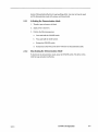
Loading a Tape
1.
To load a reel of tape, unlock the supply hub by pressing the inside of its
three reel clamps.
2.
Place the tape reel over the hub with the label facing out.
3.
Lock the reel to the hub by pressing the outside of all three reel clamps.
4.
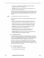
Thread the tape as indicated by the raised arrows on the surface of the casting. Refer to Figure 2-1.
5.
Wrap the end of the tape around the take up hub such that a clockwise rotation winds the tape onto the hub and rotate the hub clockwise at least three
turns.
6.
2-2
Hold the supply reel and rotate the take up hub until all slack is removed.
Controls and Operation
500250 K
Supply Hub
Figure 2-1
Threading the Tape
7. Turn on the power and press the LOAD switch to initiate the load sequence.
a.
After a short pause, the tape will move forward.
b.
After the BOT marker passes the head, the tape will be moved in reverse
until the BOT marker is in front of the head.
c.
The LOAD indicator will then illuminate, indicating the tape is at load
point, or BOT.
d.
The drive automatically sends the ONLINE and READY signals to the
interface, indicating that the drive is ready to operate. The ONLINE indicator will be illuminated.
Should the tape fail to load properly due to an operator error, the drive will normally
terminate the load sequence and display a load fault by flashing the LOAD indicator.
Thread the tape properly and press the LOAD switch to restart the load sequence.
2.2.3
Loading with Tape Already Threaded
If the tape is threaded but not tensioned, turn on the power, remove the slack, and
press the Load switch.
2.2.4
Loading Near EDT
To tension the tape when most of it is on the take up reel:
1. Make certain the EOT marker is on the supply reel.
2. Remove all slack.
3. Press LOAD while holding the FPT switch to compensate for the large amount of
tape on the take up reel.
500250 K
Controls and Operation
2-3
If the tape comes off the supply reel, moisten the last two inches and lay it over the
top of the supply reel. Turn the reel counter-clockwise so that the tape winds onto the
reel. Continue winding the tape onto the reel for five turns past the EOT marker.
Hold the FPT switch before pressing the LOAD switch and then hold both for one second to initiate the load sequence. The drive will tension and rewind the tape to BOT.
2.2.5
Unloading a Tape
1. If the tape is stopped and not at BOT, take the drive offline and press the
LOAD switch to rewind the tape.
2. When the tape is at BOT and the drive is offline, pressing the LOAD switch
initiates an unload sequence. The drive will wind the tape onto the supply
reel until the leader comes off the take up hub.
3. Press the inside of the three supply reel clamps, and then remove the reel
from the supply hub.
The drive will also respond to a combination rewind-unload signal from the host.
2.2.6
File-Protecting the Drive
You may place the drive into and out of the file-protected state when the tape is at
BOT by toggling the FPT switch until the FPT indicator illuminates.
2.2.7
Changing Data Densities
To read prerecorded tapes, you must first configure the drive to operate at the density
of the tape to be read. 1600 cpi is the most commonly used density. You can also enable the Automatic Density Select option described in Section 3.1.7.
When writing on a tape from BOT, you must choose the operating density. When appending data to a prerecorded tape, you must first configure the drive to operate at
the density at which the tape was originally written.
2.2.8
Aborting Runaways
Occasionally it may be necessary to abort a tape operation. This is preferably done by
the application program. If the application program is unable to abort a read or write,
you may place the drive offline manually by pressing and holding the ONLINE switch
until the tape stops completely. This should also terminate the application program.
Caution!
2.3
Taking the drive offline while writing can result in an incomplete block being recorded on the tape, with subsequent loss of data.
Using the Demonstration Mode
When the drive is in the demonstration mode, it will shuttle the tape at both low and
high speeds, gradually moving the tape towards EaT. When the tape reaches EOT,
the drive will rewind the tape reenter the shuttle mode. This provides an effective
2-4
Controls and Operation
500250 K
means of demonstrating the drive's tape handling ability. Any size reel may be used,
and the demonstration mode will continue until deactivated.
2.3.1
Activating the Demonstration Mode
1.
Thread a tape and remove all slack.
2. Apply power to the drive.
3.
2.3.2
Perform the following sequence;
a.
Press and hold the ONLINE switch.
b.
Press and hold the LOAD switch.
c.
Release the ONLINE switch.
d.
Release the LOAD switch. The drive will enter the demonstration mode.
Deactivating the Demonstration Mode
To deactivate the demonstration mode, press the ONLINE switch. The drive will rewind the tape and place itself online.
500250 K
Controls and Operation
2-5
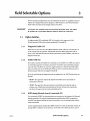
Field Selectable Options
3
Several operating configurations may be selected by the dealer or qualified personnel.
Options are changed with push-on jumpers or DIP switches on the Write/Controller
PCBA which is located on the hinged chassis of the drive.
DANGER!
3.1
ACCESSING THE JUMPERS AND DIP SWITCHES REQUIRES THAT THE DRIVE
BE OPENED BY A QUALIFIED SERVICE PERSON. REFER TO CHAPTER 8.
Option Switches
An eight position DIP switchbank (SW A) is located on the upper part of the
Write/Controller PCBA with switches numbered Sl through S8.
3.1.1
Diagnostic Enable (Sl)
When Sl is on, the drive is in the offline diagnostic mode; when Sl is off, the drive is
in the normal mode of operation. Information about the offline diagnostic mode is
given in the 1260 Technical Service Manual (document number 500244.) The drive is
shipped with Sl off.
3.1.2
Enable ICER (S2)
S2 is used to control correctable error reporting. A correctable error (CER) is a data error which the tape drive can detect and correct "on-the-fly" and is therefore transparent to the host. The drive can correct a single-track error in the PE and GCR modes,
and a two-track error in the GCR mode. When an error is corrected, the data sent to
the host is good. The drive is shipped with S2 off.
S2 is also used during the diagnostic mode as explained in the 1260 Technical Service
Manual.
· 82 ON - The tape drive reports all detected correctable errors and sends corrected data to the host.
82 off - The tape drive does not report any correctable errors during read operations, but will still send corrected data to the host. During write operations,
the drive will report only two-track correctable errors.
3.1.3
IDBY during Filemark Search Commands (S3)
Two variations of IDBY line characteristics are prevalent in the industry for Filemark
Search operations. The original implementation specified that IDBY be toggled as
each IBG was detected during the search to provide a way of counting blocks without
using read strobes.
A later implementation specifies that IDBY remain true until the filemark is found, allowing IDBY to indicate end-or-operation to the host. The 1260 tape drive may be
500250 K
Field Selectable Options
3-1
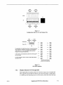
configured by S3 to provide either implementation (see Table 3-1.) The drive is
shipped with S3 off.
S3
IDBY TOGGLES
IMPLEMENTATION
On
At each IBG
Original
Off (Factory default)
Only after FMK found
Later
I
I
Table 3-1
IDBY/Filemark Search Options
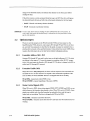
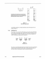
3.1.4
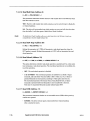
Filemark Gap Length (S4)
The early ANSI standards specify a leading gap of 3.5 inches for filemarks, followed
by the standard IBG CO.3 inch for GCR and 0.6 inch for PE.) Newer revisions of the
standards no longer require the space-wasting 3.5 inch leading gaps. The 1260 tape
drive provides a tape-saving option of writing standard IBG-Iength leading gaps. This
feature is selected by setting S4 ON, saving approximately 3 inches of tape for each
file mark written. Depending upon the tape format, this can result in a substantial increase in formatted tape capacity. The drive is shipped with S4 off.
· S4 off - Normal Gap. Selects the standard filemark gap length of 3.5 inches.
• S4 ON - Short Gap. The filemark gap itself is zero, allowing more efficient tape
use.
0.6 INCH (PE)
0.3 INCH (GCR)
-
I
IBG
~
3.5 INCH NORMAL FILEMARK GAP
0 INCH (SHORT FILEMARK GAP)
-
I
IBG
.6INCH (PE)
03 INCH (GCR)
.
~
~--~------------------------------~-----
BLOCK N
I
FILEMARK GAP
FILEMARK
BLOCK
N+1
Figure 3-1
Filemark Gaps
3.1.5
Extended Write Gaps (S5 and S6)
The nominal interblock gap (IBG) is 0.6 inch. S5 and S6 are used to extend this distance during writing to allow the host more time to fetch the next block. Extending
the IBG reduces the amount of data which will fit on a tape, but may allow the tape to
stream, allowing for faster system throughput.
If the IBG is extended and the host does not issue another write command within the
specified distance, the drive will stop and reposition the tape. The next IBG will then
3-2
Field Selectable Options
500250 K
be the nominal 0.6 inch. If the host issues the write command in less than the specified distance, the drive will immediately start writing and the IBG will be less than
the maximum selected.
Table 3-2 lists the four possible write IBG settings. The drive is shipped with S5 and
S6 off (0.6 inch.) They have no effect on read operations.
Note:
Models 1260B and 12605 use
modification of the IBG.
a 256K buffer for better system throughput, and do not require
85
86
Off
Off
0.6 inch
Off
On
1.8 inches
On
Off
5.4 inches
On
On
16.2 inches
Table 3-2
Write IBG Switch Settings
Note:
3.1.6
Extending the write IBG affects the maximum amount of data that will fit onto a tape. Use
the smallest setting which keeps the tape streaming during writing.
Default Density (S7)
The drive will power up with either 1600 or 6250 cpi density selected, according to the
position ofS7:
• 87 ON - 6250 cpi (factory default)
• 87 off - 1600 cpi
3.1.7
Automatic Density Select (S8)
The 1260 tape drive provides an Automatic Density Selection feature. This feature is
disabled when the drive is shipped but may be enabled by setting S8 to the OFF position. Do not confuse this feature with the Default Density Selection option described
in Section 3.1.6.
When a tape is initially loaded, the Automatic Density Selection feature causes the
drive to read the Identification (ID) burst on the tape. If the ID burst is valid and the
first command is a read command, the drive will automatically switch to the density
indicated by the ID burst, eliminating the problem of determining the density of a prerecorded tape. When the Automatic Density Selection takes place, the drive will
500250 K
Field Selectable Options
3-3
change to the detected density and indicate that density on the front panel before
reading the tape.
If the drive receives a write command while the tape is at BOT, the drive will ignore
the detected density (if any) and will write at the density indicated on the front panel.
· 88 ON - Manual read density selection (default)
• 88 off - Automatic read density selection
Summary: To read a tape, load it and start reading. The drive will determine the correct density. To
write a tape, make certain the desired density is indicated on the front panel before initiating the write operation.
3.2
Option Jumpers
There are several jumpers on the Write/Controller PCBA and one jumper on the
ReadIFormatter PCBA; however, only jumpers WI through W9 and W13 are of interest, and only those jumpers are described in this guide. A jumper is installed when a
shorting bar is present at the specified location. Unless otherwise noted, 1260S drives
requires that all jumpers be set to their factory default (shipping) positions.
3.2.1
Formatter Address (WO - W7)
Jumpers WO through W7 are used to select anyone of eight addresses (0-7.) To select
an address in the range of 1-7, move the jumper to a position within WI-W7, respectively. Only one jumper is allowed at WO through W7. The drive is shipped with WO installed and WI through W7 removed.
3.2.2
Formatter Enable (W8)
When W8 is set to REQ (REQuired), the drive will not respond to host commands unless IFEN is true. To allow the drive to respond to host commands regardless of the
state of IFEN, set W8 to IGNORE. The drive is shipped with W8 set to REQ.
W8 at REQ - respond only when IFEN is true;
W8 at IGNORE - respond regardless of the state of IFEN.
3.2.3
Status Control Signals (W9)
When W9 is set to FSEL, drive status signals IRWD, IFPT, ISPEED and IONL are enabled whenever the formatter has selected a drive. When W9 is set to ONLSEL, these
signals are enabled only when the formatter has selected a drive and the tape is
loaded and not rewinding. The drive is shipped with W9 set to FSEL.
W9 at F8EL - formatter must select the drive;
W9 at ONLSEL - formatter must select the drive and tape must be loaded and not rewinding.
3-4
Field Selectable Options
500250 K
3.2.4
Wl0,Wll,W12
WI0 is factory set to 27256 and Wll to LO; they should not be moved. W12 is used for
testing and does not affect drive operation.
3.2.5
IFEN Abort (W13)
To cause IFEN to abort drive operations regardless of the position ofW8, remove
W13, and the drive will abort read, write, and erase operations when IFEN goes false.
To disable the abort function of IFEN, install W13. The drive is shipped with W13 removed.
WI3 omitted - Low-to-high edge of IFEN will abort read or write/erase operations;
WI3 installed - IFEN will not abort operations.
3.2.6
Read/Formatter Wl
WI on the ReadIFormatter PCBA allows the IHIDEN8 signal to reach the interface.
IHIDEN8 will be high when operating at 1600 cpi, and will be low when operating at
6250 cpi. Only 12608 drives are shipped with WI installed.
500250 K
Field Selectable Options
3-5
4
Preventive Maintenance
4.1
Preventive Maintenance Schedule
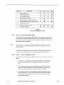
Table 4-1 lists the periodic maintenance required in a normal environment to achieve
the anticipated life of the tape drive and to maximize data reliability. A "normal" environment is considered to be an office environment free of smoke, dirt and excessive
dust.
INTERVAL
DAILY
ITEM
Clean head
Clean reference guides (2)
Clean tape cleaner
WEEKLY
Clean tachometer roller
Clean fixed roller
18 MONTHS
Perform all adjustments
Table 4-1
Preventive Maintenance Schedule
4.1.1
Why Preventive Maintenance Is Necessary
As magnetic tape ages, tiny oxide particles on the coated side of the tape loosen and
flake away. While most of these loose oxide particles will be caught by the tape
cleaner, some will be deposited on the head. If allowed to accumulate, the data reliability of the tape drive will be adversely affected. This is usually first noticed by infrequent recoverable data errors progressing to the point where tapes simply cannot be
read. Because the tape cleaner removes the larger particles of dirt and dust, it must
be periodically cleaned along with the oxide build-up on the head if maximum data reliability is to be achieved.
If allowed to build up on the write head gaps, the oxide can act much like a keeper
across a magnet and reduce the magnetic saturation of the flux reversals on the tape.
A similar buildup on the read head gaps can cause a reduction in the induced signal
from the tape. In severe cases, the build-up can actually lift the tape away from the
head surface, further reducing signal strength.
Dirt, dust and oxide particles can also accumulate on the tape guide surfaces and
flanges. If allowed to accumulate, they can be transferred to the recording side of the
tape when it packs onto the supply and take up reels. In extreme situations, heavy accumulations on the guide surfaces can induce a skew effect resulting in data errors
most noticeable when reading tapes generated on other drives.
500250 K
Preventive Maintenance
4-1
4.1.2
Frequency of Preventive Maintenance
In addition to the "normal" environment assumed by the preceding preventive maintenance schedule, several other factors, if present, will require more frequent tape cleaning:
• Age and condition of the tape. As previously stated, oxide particles tend to
flake off older tapes more readily than off newer ones. The more that older
tapes are used, the more frequently the tape path will have to be cleaned.
• General cleanliness of the operating environment. Tape drives which are operated in dusty, smokey, or high humidity environments, or in machine shops or
heavy manufacturing or industrial areas will require more frequent cleaning
than those which are operated in office environments or in computer rooms.
• Tape handling and storage. The use of improperly handled and/or stored tapes
will require more frequent tape path cleaning. Tapes which are left on work
benches will accumulate dust on the reel flanges which will eventually work its
way into the tape path. Tapes which have been partially unwound onto the
floor or which have finger prints will pick up dirt and transfer it directly to the
tape cleaner, which then requires more frequent cleaning.
• Amount of tape which has run through the tape path. Tape drives which process several thousand feet of tape each day will require more frequent cleaning
than tape drives which are used only a few minutes a day.
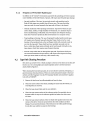
4.2
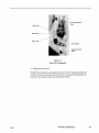
Tape Path Cleaning Procedure
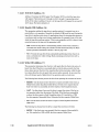
Dirt shows up as dark brown or black smudges on the face of the head and is often difficult to see. Use a strong light and a small inspection mirror to see the head more
clearly. Refer to Figure 4-1.
When cleaning the head and tape path, do not use abrasive materials, detergents, or
general purpose cleaning solutions. These can cause permanent damage to the head
surface and roller bearings. Use only 91% isopropyl alcohol and nonabrasive applicators such as TexPads®.
4-2
1.
Remove the head cover by pulling straight out from the base.
2.
Clean the entire surface of the head, including the erase head. Rub firmly until all deposits are removed.
3.
Clean the tape cleaner blade and the area behind it.
4.
Clean the tape contact surface of the reference guides. Be especially alert to
deposits under the caps on the reference guides and make sure these areas
are clean.
5.
Clean the tape contact surfaces of the two black roller guides located near the
corners of the drive. Clean the areas between the roller surfaces and their
flanges. To prevent deterioration of the lubricant in the roller guide bearings,
do not allow any solution to seep into the bearings.
Preventive Maintenance
500250 K
Take up Reference
Guide
Read Head
Write Head
Erase Head
Supply Reference
Guide
Figure 4-1
Head Area Components
6.
Reinstall the head cover.
TexPads® are individually sealed pads premoistened with 91% isopropyl alcohol and
are ideal for head and tape path cleaning. They can be obtained from Qualstar or directly from The Texwipe Company by calling (800) 284-5577.
500250 K
Preventive Maintenance
4-3
Specifications
5
1260 series tape drives write and read digital data on nine-track magnetic tape and
operate in the streaming mode for greater speed and efficiency. A separate read head
located downstream from the erase and write heads allows simultaneous read-afterwrite operation and provides for maximum data reliability.
All models contain an embedded formatter which uses the Pertec interface. Tape controllers are available to adapt this interface to nearly any modern computer.
Models 1260 Band 1260S provide special features. Model 1260B contains a 256K data
buffer. Model 1260S is designed for use with the Small Computer Systems Interface
(SCSI) and contains a SCSI PCBA with an on-board 256K data buffer.
5.1
5.1.1
Data Specifications
Data Formats
All formats are ANSIJIBM compatible.
• 1600 cpi Phase Encoding (PE) at 50 inches per second (ips)
• 6250 cpi Group Coded Recording (GCR) at 12.5 ips
5.1.2
Data Transfer Rate
• 80 and 78.125 Kilobytes per second at 1600 and 6250 cpi respectively
• 40 Kilobytes to 312 Kilobytes per second peak, model 1260B
5.1.3
Media Requirements
The drive operates reliably using any tape meeting the requirements of ANSI X3.401093 and certified for 6250 cpi. Defective tapes and tapes which have been damaged
or subjected to heavy wear may not pack properly and should not be used. The drive
supports reel sizes from 6 to 10.5 inches, and both 1.5 and 1.0 mil tape.
5.2
Data Capacities
Data capacity is expressed in megabytes. The length of the tape is defined as the distance between the BOT and EOT reflective tabs. The data capacity is directly proportional to the tape length. The data capacity of a tape is determined by several factors:
• Length of Tape
• Recording Density
• Block Length
• IBGLength
500250 K
Specifications
5-1
• Number of Filemarks
• Filemark Gap Length
• Erased Areas on the Tape
5.2.1
Tape Length
Tape length is defined as the distance between the BOT and end of tape (EaT) reflective markers. The data capacity is directly proportional to the tape length.
Tapes frequently wear out near the beginning of tape (BOT) tab as this is the area of
greatest use. Tapes which are worn near the beginning can receive new life by cutting
off the first 25 to 50 feet and affixing a new BOT reflective tab. This tab must be located 16 ±2 feet from the beginning of the tape and positioned on the outside surface
of the tape at the edge nearest the tape reel label.
5.2.2
Recording Density
The drive provides recording densities of 1600 and 6250 cpi. If data were written in
one continuous block from BOT to EaT, a tape could hold almost four times as much
data at 6250 cpi than it could at 1600 cpi.
5.2.3
IBG Length
Data is not normally written in one continuous block, but in a series of individual
blocks, each separated by in IBG. The length of the IBG is 0.6 inch (0.3 inch in GCR.)
Because the IBG is an erased area of tape, the total data capacity of a given tape is reduced by the total accumulative length of the IBGs.
5.2.4
Block Length
The number of data characters per block versus the IBG size greatly affects the
amount of data that will fit on any specified tape length. As the block length increases, the number ofIBGs in a given length of tape decreases, thereby increasing
the data capacity.
In addition, each data block contains a preamble and a postamble (required to decode
the data) which adds to the overall block length. The length of tape required for any
PE data block can be determined by adding 82 to the number of characters and dividing the sum by the data density and then adding the IBG length. GCR block length is
138 characters, plus 14 characters for every 1106 data characters.
5.2.5
Number of Filemarks
A filemark is a uniquely recorded mark on the tape which the system can use to group
data blocks together into files. In addition to the standard IBG, each filemark is preceded by a 3.5 inch filemark gap, and there is an IBG between a file mark and the following data block. As the number of file marks on a given length of tape increases, the
data capacity for that length decreases.
5-2
Specifications
500250 K
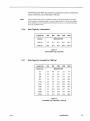
The following tables define data capacities in megabytes and assume a fixed block
length, no filemarks, and an IBG length of 0.62 inch.
Note:
5.2.6
While all Qualstar tape drives are capable of reading or writing data blocks of any length,
not all computers are equally capable. A maximum data block size of 32768 bytes is generally acceptable, but some computers have maximum limits as low as 2048 bytes (the maximum size specified by ANSI.)
Data Capacity, Unformatted
Length (ft):
300
Density
600
1200
2400
3600
MEGABYTES
1600 cpi
5.8
11.5
23.1
46.1
69.2
6250 cpi
22.5
45.0
90.0
180.0
270.0
Table 5-1
Unformatted Tape Capacities
5.2.7
Data Capacity, Formatted at 1600 cpi
h (ft):
300
600
1200
2400
MEGABYTES
Block Size
80
0.4
0.8
1.6
3.2
4.8
128
0.6
1.2
2.4
4.9
7.4
256
1.1
2.2
4.4
8.9
13.3
512
1.8
3.7
7.4
14.9
22.3
1024
2.8
5.6
11.2
22.5
33.7
2048
3.8
7.5
15.1
30.2
45.3
4096
4.6
9.1
18.3
36.5
54.9
8192
5.1
10.2
20.4
40.7
61.1
16384
5.4
10.8
21.6
43.2
64.8
32768
5.6
11.2
22.3
44.6
66.9
Table 5-2
Formatted Tape Capacities, 1600 cpi
500250 K
Specifications
5-3
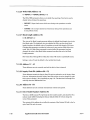
5.2.8
Data Capacity, Formatted at 3200 cpi
Length (ft):
300
600
Block Size
1200
2400
3600
MEGABYTES
80
0.4
0.9
1.7
3.4
5.1
128
0.7
1.3
2.7
5.4
8.1
256
1.2
2.5
5.1
10.2
15.2
512
2.3
4.6
9.2
18.3
27.4
1024
3.8
7.6
15.3
30.5
45.8
2048
5.7
11.5
22.9
45.0
68.8
4096
7.7
15.3
30.6
61.2
91.9
8192
9.2
18.4
36.8
73.6
110.4
16384
10.2
20.5
40.9
81.8
122.8
32768
10.8
21.7
43.3
86.7
130.0
Table 5-3
Formatted Tape Capacities, 3200 cpi
5.2.9
Data Capacity, Formatted at 6250 Cpi
T ....... n-th
(It):
300
Block Size
600
1200
2~~~
nnhh
UUUU
MEGABYTES
80
0.6
1.3
2.7
5.3
8.0
128
1.0
2.1
4.2
8.4
12.6
256
1.9
3.9
8.0
16.0
24.0
512
3.6
7.2
14.7
29.4
44.2
1024
6.2
12.4
25.3
50.6
75.9
2048
10.1
20.2
39.5
79.0
118.5
4096
13.9
27.9
54.9
109.8
164.7
8192
17.2
34.5
68.2
136.4
204.6
16384
19.5
39.0
77.6
155.2
232.8
32768
20.9
41.8
83.3
167.7
250.0
Table 5-4
Formatted Tape Capacities, 6250 Cpi
5-4
Specifications
500250 K
Error Codes and Operational Failures
6
Operational faults can arise from operator error, controller error, and drive faults.
The tape drive identifies these errors and stops operation until they are corrected (if
possible) or acknowledged by the operator.
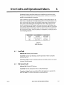
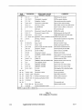
Load and FPr errors are directly identified by flashing LOAD or FPr indicators. All
other errors are identified by a two-digit flashing code on the ONLINE indicator. The
drive communicates the two-digit code by flashing the first digit count followed by a
short pause and then flashing the second digit count. After a longer pause, the sequence is repeated. The code will flash until either the operator acknowledges the error by pressing the ONLINE switch, or until power is removed. Table 6-1 summarizes
detected fault conditions. Following the table, each fault condition and possible remedies are described in detail. All fault conditions are identified by a combination of one
or more flashing indicators.
INDICATOR
FAULTIERROR
LOAD
Load Error
TO RECOVE
FPT
File Protect Error
Press FPT
ONL
Other Errors
Press ONL
Press LOAD
Table 6-1
Fault Indications
6. 1
load Fault
Indicated By: Flashing LOAD indicator.
Caused By: Improper tape threading, excessive tape slack or failure to properly
clamp the tape reel.
Corrective Action: Correct the situation and press the LOAD switch for one second
to resume the load sequence.
6.2
File Protect Fault
Indicated By: Flashing FPr indicator.
Caused By: The host attempted to write on a file-protected tape.
Corrective Action: Correct any problem with the host program, or unprotect the
tape. Then press FPr switch for one second to resume operation.
500250 K
Error Codes and Operational Failures
6-1
6.3
Read After Write Fault
Indicated By: Error Code 63.
Caused By: Failure to read the data being written. The tape could be incorrectly
threaded or there could be an internal drive fault.
Corrective Action: Press the ONLINE switch to resume operation. The last data
written will not be recoverable. Operator intervention may be required to inform the
host of this condition.
6.4
Start/Position Fault
Indicated By: Error Code 36.
Caused By: Failure to reach operating speed within a specified time, or failure to
properly position the tape for a read or write operation. This can be caused by improper threading, excessively low AC line voltage, or by an internal drive fault.
Corrective Action: Press the ONLINE switch to return to the pre-loaded state, then
perform a load operation. If the tape is past BOT, it will automatically reverse and return to BOT. If this fault remains, check the AC line voltage.
6.5
Write/Erase Power On Fault
Indicated By: Error Code 39.
Caused By: The drive has detected write or erase current when it should be off. This
is an internal drive fault.
Corrective Action: Press the ONLINE switch for one second to initiate an unload sequence. Reset the power and retry the operation. If the fault persists, the drive requires service.
6.6
Write/Erase Power Fail Fault
Indicated By: Error Code 61.
Caused By: No write or erase current detected during a write operation. This is an internal drive fault.
Corrective Action: Press the ONLINE switch for one second to initiate an unload sequence. Reset the power and retry the operation. If the fault persists, the drive requires service.
6.7
Motion Fault
Indicated By: Error Codes 31 through 35 and 37, 38.
Caused by: An internal drive fault has occurred, or the tape has come off the supply
reel. Running off the supply reel can be attributed to one of three possible causes:
1. The controller failed to recognize End-of-Tape signal
6-2
Error Codes and Operational Failures
500250 K
2.
No EOT marker on the tape
3. The drive failed to sense the EOT tab.
COITective action:
1.
Press the ONLINE switch to return to the pre-loaded state
2.
Perform a load operation.
3. If the tape is past BOT, it will automatically be returned to BOT. If the tape has
come completely off of the supply reel,
6.8
a.
Moisten the first two inches to help the end to adhere to the supply reel
hub;
b.
Lay the end of the tape over the top of the reel;
c.
Turn the reel counter-clockwise so that the tape winds onto the reel;
d.
Continue winding the tape onto the reel for five turns past the EOT
marker;
e.
Hold the FPT switch down while pressing the LOAD switch to initiate
the load sequence. The tape will load, then rewind to BOT.
BOT Fault
Indicated by: Error Code 41.
Caused by: No BOT marker on the tape, or the drive failed to detect the BOT
marker. Missing BOT tab or by an internal drive fault.
Corrective action: Press the ONLINE switch to return to the pre-loaded state. After
checking for a BOT marker, repeat the load operation. If the failure persists, the drive
requires servicing.
6.9
12605 Error Indications
The 1260S contains a SCSI PCBA which also performs a self-test at power up. If this
self-test fails, an indication is given on the display LEDs located on the SCSI PCBA.
For information regarding the SCSI PCBA self-test and failure indications, refer to
Chapter 7.
500250 K
Error Codes and Operational Failures
6-3
Supplemental SCSI Drive Information
7
The term SCSI stands for "Small Computer Systems Interface". Information about
this interface can be found in the ANSI SCSI-2 document, #X3T9/89-042. This chapter
describes how to connect a Qualstar 1260S tape drive to a SCSI bus and how to configure the tape drive for various options and modes of operation in a SCSI system. While
a description of SCSI is beyond the scope of this guide, a physical description of the
SCSI bus as it relates to the tape drive is provided to help you understand the principles of drive installation, bus termination, and address (device ID) selection.
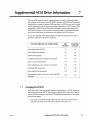
Due to the complexity of the SCSI-2 Adapter, the following quick reference index is
provided to guide you to the section of interest.
SEE
SECTION
STARTING
ON PAGE
Just changing the SCSI ID
7.1
7-1
SCSI cables and connectors
7.6
7-5
SCSI bus termination
7.7
7-6
Configuration switches, indicators, and jumpers
7.8
7-8
How to reset the SCSI PCBA
7.9
7-11
The configuration modes and how to enter them
7.10
7-11
Changing SCSI parameters
7.11
7-15
All available SCSI parameters
7.12
7-16
Setting other options in the drive to work with SCSI
operation
7.13
7-31
FOR INFORMATION ON THESE ITEMS,
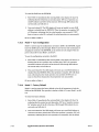
7.1
Changing the SCSI ID
Read this section if you have already connected your tape drive to a SCSI system and
only need to change the SCSI ID from the factory default of 5 to some value. Information on SCSI bus terminators and other SCSI configuration parameters is given elsewhere in this chapter.
1.
500250 K
Gain access to the SCSI-2 Adapter PCBA by removing the rear cover from the
tape drive. The cover screws are shown in Figure 7-9 on page 7-34.
Supplemental SCSI Drive Information
7-1
Note:
Figure 7-8 on page 7-33 will help you locate the switches and indicators mentioned in the
following steps.
2.
Locate Sl near the top of the SCSI-2 Adapter. The individual switches on Sl
are labeled 1 through 8, left to right, and are arranged in a binary fashion,
with the MSB on the left (1) and the LSB on the right (8).
3. Set all switches on Sl off.
4.
Locate S3 near the bottom of the SCSI-2 Adapter and set all switches off.
5. Apply power to the tape drive. After about one second, the current SCSI ID
will appear on the LEDs.
6.
Set switch 3 on S3 on, and set 1, 2, and 4 off.
7.
Set the desired SCSI ID on S1. For example, to set the SCSI ID to 1, set
switch 8 on and the rest off; to set the SCSI ID to 2, set switch 7 on and the
rest off. To set the SCSI ID to 3, set switches 8 and 7 on, and the rest off, etc.
8.
Press S2 (to the right ofS1) for less than two seconds.
9.
Set all switches on S3 off.
10. Set all switches on Sl off. The new SCSI ID will appear in the green LED indicators, indicating that the drive is now configured to respond to the new
SCSIID.
11. Set switch 2 on S3 on, and set 1, 3, and 4 off.
12.
Press and release S2.
13. When the LEDs stop flashing, set all switches on S3 off. The new SCSI ID is
now saved and will be retained when the drive is powered off and back on.
14. Turn power off and reinstall the rear cover.
7.2
Model Identification
A Qualstar 1260 Series tape drive with the SCSI-2 option is model 1260S.
7.3
7.3.1
Model 1260S Description
General
The 1260S is a Model 1260 to which a SCSI adapter and necessary mounting hardware have been added. The adapter is a printed circuit board assembly which is referred to in this document as the SCSI PCBA. The 1260S supplies the necessary
power for the SCSI PCBA, which communicates with the tape drive via the Pertee interface connectors J1 and J2.
7-2
Supplemental SCSI Drive Information
500250 K
The 1260S is attached to the system via a cable known as the SCSI bus. This SCSI
bus may be shared with other SCSI peripherals or devices. Each device, in turn, may
have up to seven similar devices (LUNs) attached to it. The 1260S supports all logical
units.
7.3.2
SCSI Power-Up Self Test
Each time the tape drive is powered up, the SCSI PCBA performs a seven-part selftest which checks the integrity of the microprocessor and its associated memory. If an
error is detected, the test sequence will halt with the illuminated LED indicating
which test failed. The display will then invert the states of all LEDs twice a second until the PCBA is reset. The tests are listed in Table 7-1.
UNLIT LED
CURRENT TEST
0
Z8 register test
1
RAM test
2
PROM sumcheck
3
5086 initialization
4
5086 FIFO test
5
DRAM test
6
EEPROM sumcheck
Table 7-1
SCSI PCBA Self Tests
7.3.3
Single-Ended Configuration
The SCSI PCBA utilizes a single-ended configuration, and provisions have been made
to accommodate either internal or external SCSI terminators. A jumper option allows
the termination power to be supplied by the SCSI PCBA or by another device on the
SCSI bus.
Caution!
7.3.4
The 1260S utilizes a single-ended SCSI interface, and is not compatible
with a differential SCSI interface. Before connecting any SCSI device to
the SCSI bus, insure that the interface types are the same.
On-Board Buffer
To facilitate data transfer operations, the SCSI PCBA uses a 256K buffer (lK = 1024
bytes) for temporary data storage. The buffer maximizes data throughput by helping
to keep the tape streaming. It also allows data to flow to and from other SCSI devices
at burst rates exceeding the data transfer rate to and from the tape.
Write operations can be performed in a buffered or unbuffered write mode. In the buffered write mode, the SCSI PCBA will return a completion status as soon as all the
data specified by the command has been transferred to the buffer. Depending upon
500250 K
Supplemental SCSI Drive Information
7-3
the number of blocks specified by the command, the transfer of data from the SCSI
bus to the buffer may be completed long before all the data has been successfully recorded on the tape. In the unbuffered write mode however, the SCSI PCBA will not return a completion status until all data specified by the command has actually been
recorded on the tape. The buffer can be controlled by the interface, or it can be forced
always on or always offby a user-specified parameter (described in Section 7.12.8 on
page 20).
During read operations, all data is transferred from the tape to the buffer before being
transferred to the SCSI bus.
The buffer features a read-ahead capability which enhances data throughput by attempting to keep the buffer full whenever the tape drive receives a Read, Read Reverse, or Space Blocks command. This is most noticeable when the host sends a
command to read one block while the tape is at BOT, or to read one block in the opposite direction (i.e., read reverse after a read forward operation). If read-ahead is enabled, the drive will continue to move the tape and read blocks into the buffer until
the buffer is full. If read-ahead is disabled, the drive will move only the amount of
tape required to read one block into the buffer. Data lready in the buffer is available
to the host immediately, without having to wait for tape motion to occur. You can disable the read-ahead function (see Section 7.12.16 for details on this option).
7.3.5
Long Blocks
A long block is a block whose length exceeds the currently-available buffer space. Note
that it is possible for the currently-available buffer space to be less than the total buffer capacity. If a long block is encountered during a read-ahead operation (described in
Section 7.12.16), the drive will stop the tape and reposition it at the beginning of the
long block. When a command to read that block is received, the SCSI PCBA will transfer the data in and out of the buffer in a first in-first out mode (FIFO operation).
Long blocks during write are usually encountered in audio or seismic applications,
and can be many megabytes long. Currently, the block length during write is limited
to 256K.
7.3.6
SCSI Configuration
You can change the configuration of the tape drive to match the requirements of a
given system using a system of option switches and light-emitting diodes (LEDs).
7.4
Differences between SCSI and the Pertec Interface
The SCSI hardware and communications protocol which exists between a host and a
peripheral device (i.e., the Qualstar tape drive) differs from the Pertec interface in
some important respects:
• The physical connectors and the principles of signal termination differ;
• The command structures differ;
7-4
Supplemental SCSI Drive Information
500250 K
• A wide variety of peripherals can be connected to the SCSI bus, but only formatted tape drives can be connected to the Pertec interface;
• Using SCSI, peripherals can communicate with each other, but peripherals using the Pertec interface can communicate only with the host;
• SCSI allows a higher data throughput rate than the Pertec interface;
• Some functions can be taken over by the peripherals, leaving the host free for
other operations.
7.5
SCSI Bus Description
The SCSI bus may be a continuous cable with a connector at each end and up to six additional connectors between the cable ends, or it may consist of a series of shorter cables which are linked together by the SCSI devices. Because the 1260S utilizes a
single-ended bus configuration, the SCSI bus cable, or cables, must not exceed six meters.
In the majority of systems, at least one of the SCSI devices on the bus is the host, with
the other devices consisting of a disk drive, a tape drive, and perhaps a high volume
storage device or a printer. To insure proper operation, you must keep several factors
in mind when configuring the SCSI bus:
• Up to eight SCSI devices may be connected to one SCSI bus;
• The device addresses (SCSI ID) range from 0 through 7;
• A device's priority on the bus is determined by its address, with SCSI ID 7 being the highest priority;
• Each device must have its own, unique SCSI ID;
• The physical location of a device on the bus has nothing to do with its SCSI ID;
• The bus must have at least two devices connected to it;
• The devices which are connected at the physical ends of the bus must have
SCSI bus terminators installed;
• The devices which are not connected at the physical ends of the bus must not
have SCSI bus terminators installed.
Device ID 7 is normally reserved for the host adapter to insure that the host has the
highest priority among the other SCSI devices. Disk drives containing system, application, and data files normally have the next priority and are assigned a device ID of 6,
while tape drives, printers, and other low priority devices have correspondingly lower
ID numbers. The factory default device ID for the 1260S is 5.
7.6
Cables and Connectors
Two identical drive connectors, wired in parallel on the side of the drive, provide a connection point to the SCSI bus. Depending upon the system's configuration, the SCSI
cable may be a shielded or unshielded flat ribbon cable, or a shielded round cable.
500250 K
Supplemental SCSI Drive Information
7-5
Because both drive connectors are wired in parallel, either may be used as an input or
an output, or for an external SCSI bus terminator. The two cable configurations are
shown in Figures 7-6 and 7-7 on page 7-32. The drive will have one of the following
types of connectors:
• SCSI Alternative 1 - This is a 50-pin male rectangular, polarized connector,
Ansley PIN 622-50FM or equivalent. This connector is flush-mounted against
the inside of the rear panel and has no locking provisions. Plug the cable connector into either drive connector;
• SCSI Alternative 2 - This is a 50-pin female "Type D" polarized connector,
AMP PIN 1-499977-0 or equivalent. It can be identified by its two rows of pin
receptacles and by the built-in locking tabs at each end. Plug the cable connector into either drive connector and secure it with the two locking tabs;
• Sun Systems Connector - This is a 50-pin female "Type D" polarized connector, AMP PIN 746789-1 or equivalent. It can be identified by its three rows of
pin receptacles and by the screw-type locks at each end. Plug the cable connector into either drive connector and secure it with the two locking screws.
7.7
SCSI Bus Termination
The SCSI terminators can be located either internally on the SCSI PCBA, or externally using a terminator plug which you provide. Power for either configuration is supplied by a dedicated termination power line on the SCSI bus; this line may be powered
by the tape drive, as explained in Section 7.7.3, by another device (or devices) on the SCSI
bus, or by both.
Note:
7.7.1
While any number of devices may supply termination power, no more than two devices, including the host adapter, may be terminated on any SCSI bus.
Internal Terminators
The 1260S is shipped with the internal SCSI terminators installed at locations RN7
and RN8 as shown in Figure 7-8 on page 7-33.
If the drive is connected to one physical end of the SCSI bus and if internal termination is desired, leave the terminators installed in RN7 and RN8 and remove the terminators from all other devices on the SCSI bus except the device which is physically
connected to the other end of the bus.
7.7.2
External Terminators
You may install an external terminator in the unused SCSI connector. If you do, you
must also remove the internal terminators at locations RN7 and RN8 on the SCSI
PCBA. Failure to do so may cause unpredictable operation.
7-6
Supplemental SCSI Drive Information
500250 K
7.7.3
Termination Power
In addition to supplying +5 volts termination power to the drive's internal and external terminators, the SCSI PCBA can provide +5 volts termination power to the SCSI
bus as well. The +5 volts is fed to the SCSI bus TERMPWR line through a protective
device (earlier units used a one-ampere fuse, Qualstar PIN 626-0014-3), a blocking diode
and an option jumper (W3) as shown in Figure 7-1.
QUALSTAR
TAPE DRIVE
+5V
Protective device
Blocking diode
Option jumper W3
;
ANOTHER
SCSI DEVICE
Missing blocking diode
)
J
-y-'--------y-'---
TERMPWR on SCSI Bus
Figure 7-1
Diagram of SCSI termination power
7.7.3.1
W3
W3 is installed at the factory so that the tape drive can provide termination power to
the SCSI bus. If for some reason you do not want the tape drive to supply termination
power, you can remove W3. If you remove W3, termination power (TERMPWR in the
drawing) must be available from another device on the SCSI bus.
7.7.3.2
Blocking Diode
The blocking diode prevents the tape drive from drawing current from other devices
on the bus when the drive is turned off.
7.7.3.3
Protective Device
If another device on the bus is supplying termination power and that device does not
have a similar blocking diode, it will draw current from the TERMPWR line when it is
switched off. A protective device in the TERMPWR supply line in the Qualstar tape
drive protects the tape drive by limiting the current which can flow from the drive to
the TERMPWR line to about one ampere. If the protective device is a fuse, the fuse
will blow.
If this is the case with your system and if the SCSI PCBA on your tape drive has a
fuse, either remove W3, or always turn the tape drive off before turning the system
500250 K
Supplemental SCSI Drive Information
7-7
off, and always turn the tape drive on after applying power to the system. Be sure
that the tape drive is never turned on when the system is off.
7.8
Switches, LEDs, and Jumpers
A non-volatile memory in the form of an EEPROM retains configuration and option information when the power is off. Each time the power is applied, the configuration
data in the EEPROM is copied to RAM. You can edit the configuration data in the
RAM by using a combination of pushbutton and DIP switches on the SCSI PCBA. The
altered data can then be stored in the EEPROM, overwriting the previous configuration data. You can also restore the original factory configuration data at any time.
Changing the configuration of the SCSI PCBA consists of the following process:
• Viewing the current configuration data in the RAM;
• Accessing the location(s) in RAM you want to edit;
• Editing the data;
• Saving the new configuration data.
Four mode select switches (S3), eight address/data switches (Sl), an on-board Load
switch (S2), and eight light emitting diodes, or LEDs, (DS7 - DSO) provide communications with the SCSI PCBA. These LEDs, Sl, and S2 are shown in Figure 7-2.
7.8.1
Switchbank S1
S1 is a bank of eight DIP switches located near the top of the SCSI PCBA (see Figure
7-8 on page 7-33) which allow you to edit the configuration data in the RAM. These
switches are used to encode two-digit hexadecimal numbers (00 through FF) as shown
in Figure 7-39.
7.8.2
Pushbutton S2
S2 is a momentary pushbutton switch whose function varies according to the current
mode, and according to the sequence of events in that mode. S2 is used to view and
edit RAM data. The following S2 events are significant:
• Pressing S2
• Releasing S2
• Holding S2 longer than two seconds before releasing it
7-8
Supplemental SCSI Drive Information
500250 K
Most
Significant
Digit
Least
Significant
Digit
OS? DS6 OS5 oS4 os3 DS2 DS1 DSO
I
00000000
1
LEOS
S2
S1
1234156?
Most
Significant
Digit
8
Least
Significant
Digit
Figure 7-2
Configuration Switch Sl, S2 and Display LEOs
Least
Significant
Digit
Most
8
0=
fQQQQI
8=
f~QQQI
1=
fQQQ~1
9=
~QQ~I
2=
&Q~QI
A=
~Q~QI
3=
&Q~~I
B=
~Q~~I
4=
.... =~~I
t~t'l~~1
c=
f~~QQI
5=
&~Q~I
0=
~~Q~I
6=
fQ~~QI
E=
~~~QI
7=
&~~~I
F=
~~~~I
81
The illustration to the right shows how to encode the least significant digit of S1 (switches 5 through 8) to a hexadecimal
number from 0 to F. The most significant digit (switches 1
through 4) is encoded the same way.
In this manner, any hexadecimal number from 00 through FF
can be encoded.
The same method is used to encode a single digit hexadecimal value on S3.
Encoding hexadecimal
numbers on the switches.
Figure 7-3
SCSI PCBA Switches
7.8.3
Display Indicators DS7 through DSO
These eight LEDs are located just above S 1. From left to right, they are labeled DS7DSO, with DS7 being the MSB and DSO being the LSB. They display a RAM address
or a RAM data byte, depending upon the current mode and the state ofS2. The value
500250 K
Supplemental SCSI Drive Information
7-9
OS7
0 =OFF
I =ON
OSO
00000000
Oisplay LEOs
The illustration to the right shows how to decode the least
significant digit of the display LEOs (083 through 080) to a
hexadecimal number from 0 to F. The most significant digit
(087 through D84) is decoded the same way.
DODD = 0
1000
=8
0001
=1
1001
=9
0010
=2
1010
=A
0011
=3
1011
=8
DIDO
=4
1100
=c
0101 = 5
1101
=0
0110 = 6
1110
=E
0111 = 7
IIII
=F
OS3- OSO,or
OS7- OS4
OS3 - oso, or
OS7- OS4
Figure 7-4
SCSI PCBA Display LEOs
on the LEDs is decoded as a two-digit hexadecimal number (00 through FF) as described in Figure 7-4.
7.8.4
Switchbank S3
S3 (see Figure 7-5) is a bank of four DIP switches near the bottom of the SCSI PCBA
and are used to enable various modes of operation. The left-most individual switch is
the most significant bit (MSB) and the right-most switch is the least significant bit
(LSB). The switches are either open (oft) or closed (on).
LSB
MSB
83 set for
Mode 0
(0000)
LSB
MSB
~
[QQ]]]
83
83 set for
Mode 2
(0010)
83
Figure 7-5
Switchbank S3
The modes are numbered hexadecimally from 0 through F but currently, only Modes 0
through 5, Mode E, and Mode F are used. Table 7-2 summarizes these modes and
their uses, which are also explained in detail in subsequent paragraphs.
7-10
Supplemental SCSI Drive Information
500250 K
7.8.5
Jumpers
The SCSI PCBA contains four jumpers, labeled WI through W4. These jumpers are
shown in Figure 7-8 and have the following purpose:
• WI - WI selects the type of EEPROM installed in position U3. If the EEPROM
is of the type 27512 (i.e., 512K), WI must be installed across pins 1 and 2. If
the EEPROM is of the type 27256 (i.e., 256K), WI must be installed across pins
2 and 3;
• W2 - W2 is used during factory test and must be installed for normal operation;
• W3 - When W3 is installed, the SCSI PCBA provides +5 volts termination vol-
tage to the SCSI bus. When W3 is removed, the termination voltage must be
provided by some other device on the SCSI bus;
• W4 - Installing a jumper across W4 disables the SCSI PCBA and holds it reset.
Momentarily shorting the pins at location W4 will reset the SCSI PCBA, the
same as if the power were cycled or as if the SCSI PCBA received a SCSI Bus
Reset. Shorting the pins at location W4 only resets the PCBA and does not
cause a SCSI Bus Reset. The Reset function is described in Section 7.9.
7.9
Resetting the SCSI PCBA
Resetting the SCSI PCBA causes several things to happen: the buffer is cleared of any
data; all pending commands are cleared; the configuration data stored in the
EEPROM is copied into the RAM; and the PCBA performs its self-test.
The SCSI PCBA can be reset by:
• Applying power (also causes a Unit Attention condition)
• Momentarily shorting the pins ofW4 together (does not cause a Unit Attention condition)
• Receiving a SCSI Bus Reset
7.10 SCSI PCBA Configuration Modes
As previously described, S3 is used to place the SCSI PCBA in a particular mode of operation. Entering any of these modes does not disable the tape drive, and the SCSI
PCBA will continue to respond to the SCSI bus.
To enter a particular mode, set the appropriate switches on S3 on. The SCSI PCBA
will be placed in that mode immediately. To enter Mode 0 (normal operating mode),
place all switches on S3 off. To enter Mode 2, place the second switch from the right
on. See Figure 7-5 and Table 7-2 for a complete list of available modes.
Note:
500250 K
The SCSI PCBA mode may be changed while the tape drive is online (i.e., the ONLINE indicator is on). Changing from one mode to another will not result in a Unit Attention condition on the SCSI bus.
Supplemental SCSI Drive Information
7-11
MODE
FUNCTION
83-1
83-2
83-3
83-4
0
Normal operation
off
off
off
off
1
View configuration data
off
off
off
ON
2
Alter configuration data
off
off
ON
off
3
Reload RAM from EEPROM
off
off
ON
ON
4
Save configration from RAM to EEPROM
off
ON
off
off
5
Return EEPROM and RAM to factory defaults
off
ON
off
ON
!
-
-
E
Factory test (factory use only)
ON
ON
ON
F
Continuous diagnostics
ON
ON
ON
6-D
No operation, no effect
i
-
i
Ii
-
off
ON
Table 7-2
SCSI PCBA Configuration Modes
7.10.1
Mode 0 - Normal Operating Mode
Setting all S3 switches off places the SCSI PCBA in the normal operating mode, and
the tape drive will respond to SCSI commands in a normal manner. In Mode 0, you
may view the contents of any memory address in RAM by setting that address on S 1
and looking at DS7 through DSO.
Note:
Because the drive is in the normal operating mode, displaying the Rl\M contents is a background operation, and there may be a delay from the time 51 is changed to the time the
display is updated.
In Mode 0, S2 is disabled and you will not be able to change the configuration data.
You may enter another mode at any time by setting the appropriate switches.
7.10.2
Mode 1 - View Configuration Data
If you want to look at the data in the RAM but do not want to change it, use Mode 1 as
follows:
1. To view data at any address, first set the desired address on Sl, and then enter Mode 1 by turning S3-4 on. The display will show the data at that address;
2. To view the data at the next (sequential) address, press S2 for less than two
seconds. Each time you press S2, the next higher address is displayed and
each time you release S2, the data at the new address is displayed;
3. To view data at other than the next address, set the desired address on Sl
and then press S2 for more than two seconds. After two seconds, the address
on the switches will be displayed, and when S2 is released, the data at that
address will be displayed.
7-12
Supplemental SCSI Drive Information
500250 K
7.10.3
Mode 2 - Alter Configuration Data
Use Mode 2 to view and to alter the RAM configuration data. The contents of the
EEPROM will not be changed. The configuration data is edited by selecting the address of the data to be changed, entering Mode 2, setting the new data on Sl, and writing that data into the selected address.
When you edit data using Mode 2, you do not change the data in the EEPROM. Furthermore, if the SCSI PCBA receives a SCSI Bus Reset, or if the power is cycled, all
changes in the RAM will be lost. To save the changes, they must be stored as described
in Section 7.10.5.
To alter the configuration data in the RAM:
1.
Determine the address which holds the data to be changed.
2.
Set the address of that data on S1.
3.
Set S3-3 ON to enter Mode 2. This accesses the address you set on Sl and displays the data at that address.
4.
Set the desired data on S1. Then:
a.
To go ahead and alter the data, press S2 for less than two seconds. When
S2 is pressed, the address to be written to is displayed. When S2 is released, the data on Sl will be written, the address will be incremented
and its data will be displayed;
b.
If you change your mind after pressing S2, just hold it pressed for more
than two seconds before releasing it. After two seconds, the address will
be changed to that currently on Sl, and that address will be displayed.
The data at the address you were viewing will remain intact;
c.
To alter the data at an address other than the one currently displayed (i.e.,
at some non-sequential address), exit Mode 2 and begin from Step 1, or
use Step 3b.
Summary: To alter memory contents, release 52 within two seconds. To abort, hold 52 longer than
two seconds.
7.10.4
Mode 3 - Reload RAM from EEPROM
If you make a mistake while editing, get confused, or for some reason wish to start
over, you can use Mode 3 to recopy the EEPROM configuration data to the RAM. Cycling power to the drive or resetting the SCSI PCBA via W 4 have the same effect, but
will also generate a Unit Attention condition on the SCSI bus. To enter Mode 3, set 83
to 3.
500250 K
Supplemental SCSI Drive Information
7-13
To reload the RAM from the EEPROM:
1.
Enter Mode 3. Immediately after entering Mode 3, the display will show 73,
indicating that the reload has not yet taken place. D87 is an "operation successful" indicator and will be off at this time. D83 through D80 indicate the
current mode, and will show 3.
2.
Press and release 82. The LED display will count up (quickly) as each RAM
address is reloaded from the EEPROM. When the operation is complete, D87
will illuminate, indicating that the reload operation was successful. If D87
does not come on when 82 is released, the reload operation was unsuccessful.
81 has no effect in Mode 3.
7.10.5
Mode 4 - Save Configuration
Mode 4 is used to copy the configuration currently in RAM to the EEPROM, regardless if the RAM data has been changed. Modes 4 and 5 are the only mechanisms of
changing the contents of the EEPROM, as its contents are not changed when the
power is shut off. To enter Mode 4, set 83 to 4.
To save the configuration currently in the RAM:
1.
Enter Mode 4. Immediately after entering Mode 4, the display will show 4, indicating that the save operation has not taken place. D87 is an "operation
successful" indicator and will be off at this time. D83 through D80 indicate
the current mode, and will show 4.
2.
Press and release 82. The LED display will count up as each RAM address is
reloaded from the EEPROM. When the operation is complete, D87 will illuminate, indicating that the reload operation was successful. If D87 does not
come on when 82 is released, the reload operation was unsuccessful.
81 has no effect in Mode 4.
7.10.6
Mode 5 - Factory Default
Mode 5 is used to restore the factory default values for all parameters to both the
RAM and the EEPROM. The operation is similar to Mode 4. To enter Mode 5, set 83
to 5.
To restore the factory defaults:
7-14
1.
Enter Mode 5. Immediately after entering Mode 5, the display will show 75,
indicating that the restore has not taken place. D87 is an "operation successful" indicator and will be off at this time. D83 through D80 indicate the current mode, and will show 5.
2.
Press and release 82. The LED display will count up as each RAM address is
restored to the factory default data. When the operation is complete, D87 will
illuminate, indicating that the save operation was successful, and the default
Supplemental SCSI Drive Information
500250 K
values for all parameters are in effect. IfDS7 does not come on when S2 is released, the restore operation was unsuccessful.
Sl has no effect in Mode 5.
7.10.7
Mode 6 through Mode D - NoOp
Mode 6 through Mode D are not currently used. Entering these modes will not affect
SCSI bus operations, and the tape drive will function normally. To enter these modes
set S3 to the appropriate value.
While in these no-op modes, DS7 will be off, and DS6 through DS4 will be on. DS3
through DSO will display a hexadecimal number indicating the number of the mode
which has been selected, with DS3 being the MSB. Pressing S2 in these modes will invert the display, providing an opportunity to test the LED indicators.
7.10.8
Mode E - Factory Test
Placing the SCSI PCBA in Mode E configures it for a continuous self-test operation.
Mode E is for factory test only and requires a specialloopback connector at J1 and J2.
7.10.9
Mode F - Continuous Self-Test
Placing the SCSI PCBA in Mode F configures it for a continuous self-test operation. In
addition to performing the normal power-on diagnostics, Mode F also tests the entire
contents of the 256K buffer. In Mode F, the SCSI PCBA will ignore the SCSI bus. To
enter Mode F, set all S3 switches on (4).
The self-test is started by momentarily shorting the pins at W4 together after entering Mode F; the self-test is stopped by taking the SCSI PCBA out of Mode F.
As each test is performed, its corresponding LED will be off, and the remaining LEDs
will be on, allowing the user to quickly verify that all LEDs are functioning properly.
The SCSI PCBA will cycle continuously from Test 0 to Test 6 until taken out of Mode
F, or until an error occurs.
If an error is detected, the display will temporarily halt with the illuminated LED indicating which test failed. The remaining LEDs will be off. The display will then invert the states of all LEDs twice a second until the user takes the SCSI PCBA out of
ModeF.
You may abort a failed test and advance on to the next test by pressing S2.
7.11 Changing SCSI Parameters
This section is a quick overview of the steps required to change any programmable
SCSI parameter. Detailed descriptions of each parameter are given in Section 7.12,
and detailed information on the various modes is given in Section 7.10 beginning on
page 7-11.
500250 K
Supplemental SCSI Drive Information
7-15
To configure the parameters:
1. Select the RAM address of the parameter to be changed using Sl (see Table 73 on page 7-18);
2. Enable Mode 2 (Alter Configuration Data) using S3;
3. Set up the data for the parameter using Sl (see Table 7-3 on page 7-18, or the
corresponding paragraph in Section 7.12);
4. Press S2 to load the data set on Sl into RAM;
5. To retain the changes when the power is turned off, save the new configuration by enabling Mode 4 using S3 and pressing S2;
6. Return the PCBA to normal operation by turning all S3 switches off.
7.12 SCSI Configuration Parameters
Switch Sl on the SCSI PCBA allows you to select the SCSI parameters defined in Table 7-3. The procedures for loading, changing and saving the parameters are described
in Section 7.10.
Note:
All configuration items, with the exceptions of write retries, read retries, and Inquiry data,
must be saved to the EEPROM (using Mode 4) and then reloaded back into the RAM (using
Mode 3 or resetting the PCBA) before they will take effect.
EXAMPLE 1: Suppose you want to change the SCSI ID from its factory default of 5 to
6, and suppose the drive is currently in Mode o.
1. The SCSI ID is stored in RAM address 00. While still in Mode 0, set Sl to 00.
The display shows the current SCSI ID of 5.
2. Next, enter Mode 2 by setting S3 to 2 (Alter Configuration Data). The display
does not change.
3. Now set the new SCSI ID on SI (06).
4. Finally, press S2 for less than two seconds. This stores the data you set on SI
in address 00. The display then shows the data in the next address (01). This
will be either 00 if SCSI bus parity is disabled, or 01 if SCSI bus parity is enabled.
7-16
Supplemental SCSI Drive Information
500250 K
EXAMPLE 2: Suppose you want to disable reading beyond the EOT tab.
1.
The READ EOT parameter is stored in RAM address OF. While still in Mode 0,
set SI to OF. The display shows the current value of the READ EOT parameter.
2. Next, set S3 to 2 to enter Mode 2 (Alter Configuration Data). The display will
show the contents of RAM address OF.
3. Now set SI to 01 (disables read beyond EOT).
4. Finally, press S2 for less than two seconds. This stores the data you set on SI in
RAM address OF. The display then shows the data in the next address (10).
7.12.1
SCSI Device ID (Address 00)
VALID VALUES = 0 - 7; DEFAULT = 5
This parameter lets you to define a SCSI Device ID from 0 to 7. The SCSI ID is independent of the drive's physical location on the SCSI bus, and depends upon the desired priority for the drive in the system. SCSI ID 0 is the lowest priority, and SCSI
ID 7 is the highest. If more than one device on the SCSI bus have the same SCSI ID,
the system will operate in an unpredictable manner.
Note:
7.12.2
The SCSI Device 10 is not the same as the Drive Address jumper on the Write/Controller
PCBA. When the SCSI PCBA is used, the Drive Address jumper on the Write/Controller
PCBA MUST be set to O.
SCSI Parity (Address 01)
o =DISABLED, 1 =ENABLED; DEFAULT =0
This parameter refers to the parity on the SCSI bus and not to the parity recorded on
the tape. The SCSI PCBA always generates parity. This option determines ifit checks
SCSI bus parity.
Note:
If one device on the SCSI bus is configured to support parity, all other devices on that SCSI
bus must also be configured to support parity, and vice versa.
DISABLED - The SCSI PCBA will not check SCSI-bus parity.
ENABLED - The SCSI PCBA checks SCSI-bus parity.
500250 K
Supplemental SCSI Drive Information
7-17
RAM
ADDRESS
00
PARAMETER
I SCSI IO
ISCSI PARITY
SCSI SYNC
SPACE WRITE
WRITE EDT
WRITE RETRIES
01
02
03
04
05
06
BUFFER SWITCH
EARLY EDT
EDM ON READ
SET INQUIRY DATA
LNG BLK
07
08
09
OA
OB
OC-OD
RD BAD DATA
RD EDT STOP
READ AHEAD
READ CER
READ RETRI ES
OE
OF
10
11
12
SELECTABLE VALUES
( DEFAULT VALUES)
0-7 (5)
COMMENTS
SCSI Device ID selection
(O=disabled), l=enabled
ISCSI bus parity detection
O=disallow, (l=allow)
Allow synchronous data transfers
(O=normal), l=read ahead
Space in Write mode switching
(O=write), l=retain
Write buffer contents when EOT sensed
(13) 00-99 BCD
Max # retries (in BCD) on write error
don't care
Not currently used
(O=normal), l=force off, 2=force on
256K buffer enable
(O=normal), l=eom, 2=1 blk
Buffering mode after Early EOT
O=no, (l=yes)
Toggles EOM check bit for EOT reads
(Qualstar), various, see Section 7.12.11 Selects Inquiry Data File
(O=stop), l=continue
Read ahead termination for long blocks
don't care
Not currently used
O=no, (l=yes)
Returns bad data to host
(O=no), l=yes
Disable read beyond EOT tab
O=off, 1=1 fmk, (2=2 fmk), 3=3 fmk
Read ahead enable/termination
(O=ignore), l=report
Inhibit reporting of read CERs
(10) 00 - 99 BCD
Max # retries on read HER
Residue count format
13
I RESIDUE
(O=normal), l=invert
14
UNLOAD
ISCSI LUN
REWRITE CER
WRITE CER
BUSY
READ HER
WRITE HER
BLOCK LENGTH
(NORMAL), INHIBIT, REWIND
Sets response to Unload command
(0)-7,8=all
SCSI LUN to which drive responds
(YES),NO
Enable retries for CERs
(ERROR), LAST, NO, RETRY, YES
Reported status of last write retry
(NOT READY), BUSY
See Section 7.12.24
(REPORT), IGNORE
Ignore hard errors when reading
15
16
17
18
19
lA
1B
1B-AF
BO -B7
B8-BF
CO-CF
DO-D3
D4 - F5
INQUIRY PARMS
INQUIRY VENDOR 10
INQUIRY PROD. 10
INQUIRY PROD. REV
(RESERVED)
F6-FD
FE
FF
DRIVE MODEL NR
CHECKSUM
(REPORT), IGNORE
Ignore hard errors when writing
0- 99 (2)
Block length x 256 in fixed block mode
don't care
Not currently used
see Section 7.12.29
Inquiry parameters
Qualstar
Eight ASCII characters
various, see Section 7.12.29
Sixteen ASCII characters
various, see Section 7.12.29
Four ASCII characters
don't care
Not currently used
00, (01), 02, 03
Reports model number
various, see Section 7.12.32
NOTE: 0 = open, or off; 1 = closed, or on.
Table 7-3
SCSI Configuration Parameters
7-18
Supplemental SCSI Drive Information
500250 K
7.12.3
SCSI Sync (Address 02)
o = DISALLOW, 1 = ALLOW; DEFAULT = 1
The SCSI PCBA supports both synchronous and asynchronous data transmission. Deciding which mode to use is a matter of initiator/target negotiation.
ALLOW - If the initiator selects the synchronous mode, the drive will transfer data in
the synchronous mode;
DISALLOW - If the initiator selects the synchronous mode, the drive will inform the
initiator that it will not operate in the synchronous mode, and will instead operate
only in the asynchronous mode.
7.12.4
Space Write (Address 03)
o = NORMAL, 1 = READ AHEAD; DEFAULT = 0
Issuing a Read or Read Reverse command places the drive in the Read mode. When in
the Read mode, the drive mayor may not perform a read-ahead operation, depending
upon the setting of the Read Ahead option (see Section 7.12.16 for details on this option). Issuing a Write command to the drive places it in the Write mode, where there
is no read-ahead operation.
This parameter determines what the drive will do if it receives a Space Blocks command when it is in the Write mode:
• NORMAL - After spacing across the specified number of blocks, the drive
stops the tape immediately. It does not switch into the Read mode or perform a
read-ahead operation.
• READ AHEAD - After spacing across the specified number of blocks, the drive
switches to the Read mode and continues to move tape and to read blocks into
the buffer until the buffer is full (i.e., it performs a read-ahead operation.) This
is advantageous if the next command is a Read or Read Reverse command, because the data will already be in the buffer and will be immediately available
to the host. However, if the next command is a Write command, a delay will occur while the drive moves the tape back across all the blocks which were read
ahead into the buffer. Only after this delay will the drive request data from the
host.
7.12.5
Write EDT (Address 04)
0= WRITE, 1 = RETAIN; DEFAULT = 0
This parameter determines whether or not the drive will write the contents of the buffer to tape when buffer operations are enabled and the EOT marker is sensed while
writing.
• WRITE - All unrecorded data in the buffer will be written to tape and the
drive will then report an End Of Medium Check Condition with the Information Bytes set to zero;
500250 K
Supplemental SCSI Drive Information
7-19
· RETAIN - The drive will complete the block being written when the EOT
marker is sensed and will not write any more data. It will report an End Of Medium Check Condition with the Information Bytes equal to the number of unrecorded bytes in the buffer;
The unrecorded data may be written to tape using the Write Filemark command or it may be recovered using the Recover Buffered Data command. Any
other tape motion command will clear the contents of the buffer.
7.12.6
Write Retries (Address 05)
VALID VALUES = 0 - 99; DEFAULT = 13
When a hard or correctable error is detected during a write operation, this parameter
defines the number of automatic retries the drive will perform before reporting an error. For each retry, the drive backspaces the tape over the block, erases a four-inch
length of tape, and then rewrites the data.
The number of write retries is entered as a binary coded decimal (BCD) number on
S1. This parameter takes effect immediately without having to be saved first.
Regardless of the value of this parameter, errors which occur while writing blocks
larger than 256K will not result in retries.
7.12.7
Address 06
This address is not currently used and the data it contains is ignored.
7.12.8
Buffer Switch (Address 07)
o = NORMAL, 1 = FORCE ON, 2 = FORCE OFF; DEFAULT = 0
This parameter determines when the SCSI PCBA will return a completion status to
the SCSI bus during write commands.
• NORMAL - The buffered write mode is enabled after the drive is powered up.
It can be disabled, and later re-enabled, via a control bit in the Mode Select
command;
• FORCE ON - The SCSI PCBA is always in the buffered write mode, and will
not respond to the buffer control bit in the Mode Select command;
. FORCE OFF - The SCSI PCBA is always in the unbuffered write mode, and
will not respond to the buffer control bit in the Mode Select command.
The buffered and unbuffered write modes are described in Section 7.3.4 beginning on
page 7-3.
7-20
Supplemental SCSI Drive Information
500250 K
7.12.9
Early EOT (Address 08)
o = NORMAL, 1 = EOM, 2 = 1 BLOCK; DEFAULT = 0
Depending upon the recording density, the block length, and other conditions when
EOT is detected, the contents of a full buffer (256K) may not fit on the remaining
amount of tape. As an aid in dealing with this situation, the drive informs the SCSI
PCBA when the tape reaches a point approximately 25 feet ahead of the EOT marker
strip. This point is known as Early EOT and occurs only during write operations.
This parameter determines the course of action when Early EOT is detected:
• NORMAL - The buffer is reduced from 256K to 64K. If there is more than 64K
of unrecorded data in the buffer, the tape drive will first wait until it has successfully recorded all but 64K before accepting another Write command. When
EOT is detected, the tape drive will report EOM to the host.
This mode of operation will prevent the possibility of running out of tape while
there is still unrecorded data in the buffer; however, the drive may not be able
to keep the tape streaming between Early EOT and the EOT marker;
• EOM - The buffer size is not reduced. The tape drive will accept further Write
commands and will keep the tape streaming. It will report EOM to the host
upon detecting Early EOT. It will NOT, however, report EOM when the EOT
marker is detected;
e
1 BLOCK - The buffer size is not reduced, but the tape drive will only accept
data from the host one block at a time. The block can be any size. The tape may
not stream.
7.12.10 EOM On Read (Address 09)
0= NO, 1 = YES; DEFAULT = 1
The setting of this parameter affects the reporting of Check Condition when the EOT
marker is detected during read operations:
· NO - The drive will not report the End Of Medium Check Condition;
• YES - The drive will report the End Of Medium Check Condition.
7.12.11 Set Inquiry Data (Address OA)
0= CUSTOM, 1-10 = Various, 3 = QUALSTAR; DEFAULT = 3
7.12.11.1
Inquiry Data File
The Inquiry Data File contains the Inquiry string which the tape drive will return to
the host upon receipt of an INQUIRY command. The following choices are available:
• QUALSTAR - The standard data file which reflects a Qualstar tape drive;
500250 K
Supplemental SCSI Drive Information
7-21
• Various others - These data files look like those returned by other vendors'
tape drives as shown in Table 7-4 on page 7-23.
• CUSTOM - This data file can be edited and used when the information in the
other data files is not accepted by the host.
The Inquiry Data File, or string, which the drive returns to the host resides in the Inquiry Data File area at RAM address BO through F5. Like the remainder of the RAM,
the Inquiry Data File area is loaded from the EEPROM each time you switch on the
tape drive.
Note:
This parameter takes effect immediately without having to be saved first.
The string is divided into five fields, each containing different information about the
SCSI device:
• Bytes 0-7 - These eight bytes of hexadecimal data (RAM locations BO through
B7) describe the type of device (i.e., a tape drive, a disk drive, a printer, etc);
• Vendor ID - These eight bytes of ASCII data (RAM locations B8 through BF)
usually contain the name of the equipment vendor ("Qualstar", for example);
• Product ID - These sixteen bytes of ASCII data (RAM locations CO through
CF) usually contain the product name, model number, etc.;
• Product Revision - These four bytes of ASCII data (RAM locations DO
through D3) usually contain revision information about the device;
• Extended Inquiry Bytes - These 34 bytes (RAM location D4 through F5) are
only sent to the host if an IBM or NCR data file is selected.
7.12.11.2 Predefined Inquiry Strings
To facilitate integration of the 12608 into a variety of SCSI systems, you can select
from a number of predefined Inquiry strings by setting a hex value at RAM address
OA. If none of these predefined files meet your needs, you can define your own custom
string by entering Mode 2 and manually changing the data using 81 and S2.
Selecting the Custom Inquiry string does NOT change the contents of the Inquiry
Data File area. Instead, whatever the file contains, whether you have changed it or
not, will be saved under the name "Custom" if Mode 4 (Save Configuration) is entered.
The Custom Data File area is 35 bytes long.
7.12.11.3 Modifying a Predefined Data File
You can modify a predefined data file as follows:
1. Set Sl to OA, the Set Inquiry Data address.
7-22
Supplemental SCSI Drive Information
500250 K
Addr.
OA
Value
Inquiry
String
Name
BO-B7
I
B8-BF
(Vendor
ID)
CO-CF
(Product ID)
DO-D3
(Prod.
Rev.)
01
Kennedy
018002021FOOO010 KENNEDY
96X2 TAPE UNIT
l.36
02
mM9348
0180010026000000
9348 MODEL 001
l.36
03
Qualstar
0180020220000010 QUAL STAR 1260S
l.36
04
Telex
01S001001FOOOOOO TELEX
l.36
05
NCRADP
01C5000027C10701 NCR ADP- 53
06
HP7980
01S002021FOOO010 HP
79S0S
l.36
07
HP88780
01S002021FOOO010 HP
SS7S0
l.36
OS
M4SCSI
01S002021FOOO010 M4 DATA
123107 SCSI
1.36
09
M4DATA
01S002021FOOOO10 M4 DATA
OPEN REEL TAPE
1.36
OA
STK
01S002021FOOO010 STK
42S0
1.36
OB
F880
01S002021FOOO010
OC
M890/891
01S0020222000010 NCR H621 0-STD-03-46MS90/ 8911
00
M990
01S002021FOOO010 NCR H621 0-STD-03-46M990
OE
M990-64K
0180020222000010 NCR H621 0-STD-03-46M990- 64K1
OF
2440 MODEL A10
00000000 *****
QUAL STAR
NCR H621 0-STD-03-46FS80
SCSI
07.021054
1.36
.36
1.36
iM995
1018002021FOOO010 CIPHER
M995
11.36
M996
j01S002021FOOO010 CIPHER
M996
[1.36
i
10
IBM
D4-F5
(Reserved)
.36
I
!
Table 7-4
Inquiry Strings
2. Set S3 to 2 to enter Mode 2; the display will show the currently loaded data (i.e.,
01 (Kennedy), 02 (IBM 9348), 03 (Qualstar), etc.
3. Set Sl to the desired data file (01 for Kennedy, 02 for IBM 9348, etc.).
4.
Press S2 for less than two seconds. The number of the data file set on Sl is written to address OA and the contents of that data file are loaded into the Inquiry
string (BO through F5).
5. Set S3 to 0 to exit Mode 2.
6. Set the address of the byte to be modified on S1. The display shows the data at
that address.
7. Set S3 to 2 to reenter Mode 2; the display does not change.
8. Set the new data on S1. Refer to Table 7-6 at the end of this chapter for ASCII
conversions.
500250 K
Supplemental SCSI Drive Information
7-23
9.
Press S2 for less than two seconds. The new data will be written into the
RAM, and the display will show the data at the next higher address. Then:
a.
If the next higher address is also to be modified, set the new data on Sl
and press S2 as before. The new data will be written at that address and
the display will show the data at the next higher address. This process
can be used as long as contiguous addresses are to be modified;
b.
If the next address to be modified is other than the next higher address,
repeat this process starting at Step 5;
10. At this point, the following possibilities exist:
• You can save the modified data file as a Custom Inquiry string while the original predefined data files remain unchanged. This is the recommended procedure. To save the modified data file as a Custom Inquiry, proceed with the next
step;
• You can test the modified data file by returning the PCBA to the normal mode
(setting S3 to 0). In this case, the modified Inquiry data file will be reported until the tape drive power is cycled, at which time the Inquiry data file area will
be reloaded according to the Set Inquiry Data parameter;
• You can save the modified data under its original name by setting S3 to 4 (Save
Configuration). This creates a "modified, predefined data file" in the EEPROM.
Each time this particular predefined data file is loaded to the RAM from the
EEPROM, the modified data will be used. This is not a recommended procedure and should be avoided;
• You can abort the editing process and reload the predefined data file into the
Inquiry data file area by setting S3 to 3 (Reload RAM from EEPROM);
• You can restore all predefined data files to their original factory defaults by setting S3 to 5 and momentarily pressing S2 (this also restores the other configuration parameters to their factory default values).
11. After all the modifications to the Inquiry string have been made, change the
Set Inquiry Data parameter to 0 as follows:
7-24
a.
Exit Mode 2 by setting S3 to 0;
b.
Set Sl to OA;
c.
Enter Mode 2 by setting S3 to 2;
d.
Set Sl to 00;
e.
Press S2 for less than two seconds;
f.
Set S3 to 4 (Save Configuration from RAM to EEPROM);
g.
Press S2 for less than two seconds. The Inquiry string is saved and will
be recalled as long as the Set Inquiry Data parameter is O.
Supplemental SCSI Drive Information
500250 K
7.12.11.4
Creating a Custom Inquiry String
A Custom Inquiry string can be created in two ways:
• Method 1 - By modifying a predefined data file. Follow the steps in Section
7.12.11.3;
· Method 2 - By manually setting each individual byte of data in the Inquiry
string to the desired value using Mode 2.
In either case, be sure to change the Set Inquiry Data parameter to 0 before saving
the configuration.
Notes:
Editing of bytes 80 through 87 must be done with care to maintain compatibility with SCSI
systems;
The 33 reserved bytes are at RAM location 04 through F5 and should not be changed. The
last 30 bytes are ASCII spaces.
7.12.12 Lng Blk (Address OB)
0= STOP, 1 = CONTINUE; DEFAULT = 0
If the Read-Ahead mode is enabled, this parameter determines what happens after
the SCSI PCBA has transferred a long block from the tape to the SCSI bus as a result
ofa Read command. The Read-Ahead mode is described in Section 7.12.16 on page 726, and long block operation is described in Section 7.3.5 beginning on page 7-4.
• STOP - After a long block has been successfully transferred, the read-ahead operation stops. It may resume during a subsequent Read, Read Reverse, or
Space command;
• CONTINUE - After a long block has been successfully transferred, the readahead operation continues without pause. If the block will not fit into the remaining buffer space, the Read command will be aborted; however, the tape
will continue to move until the end of the long block is detected. At that time,
the drive will reposition the tape back to the beginning of the long block.
If the block is relatively short (one or two megabytes), the reposition time is insignificant. If the block is several megabytes long, the reposition time becomes
significant and it may be more efficient to have the drive stop the tape (i.e., the
STOP option should be selected.)
7.12.13 Address OC - 00
These address are not currently used and the data they contain is ignored.
500250 K
Supplemental SCSI Drive Information
7-25
7.12.14 Read Bad Data (Address 0)
0= NO, 1 = YES; DEFAULT = 1
This parameter determines whether the drive will transfer data to the SCSI bus when
that data contains an error.
YES - The drive will transfer data which contains an error and will report a Media Error Check Condition;
NO - The drive will not transfer data which contains an error and will clear that data
from the buffer. It will also report a Media Error Check Condition.
Note:
The Media Error Check Condition will occur in both cases but in the YES case, it may be accompanied by an Incorrect Length Indicator (ILl).
7.12.15 Read EDT Stop (Address OF)
0= NO, 1 = YES; DEFAULT = 0
Setting this parameter to 1 (YES) will terminate a read-ahead operation when the
EOT marker is sensed. Setting this parameter to 0 (NO) will not terminate the readahead operation.
7.12.16 Read Ahead (Address 10)
0= OFF, 1 = 1 FMK, 2 = 2 FMKS, 3 = 3 FMKS; DEFAULT = 2
This option determines whether read-ahead operation is enabled and if so, what condition terminates a read-ahead operation. The read-ahead operation is not available during write operations.
• OFF - The read-ahead operation is disabled;
• 1 (2) (3) F:MK(S) - The read-ahead operation is enabled for any Read or Space
command, and ends either when the buffer is full or when one, two, or three sequential filemarks are encountered, according to which option has been set.
The read-ahead operation will resume when a Read, Read Reverse, or Space
command is processed after the filemark(s) is (are) transferred to the host.
Note that two sequential filemarks usually indicate logical EOT.
7.12.1 7 Read CER (Address 11)
0= IGNORE, 1 = REPORT; DEFAULT = 0
This parameter determines whether or not correctable errors (CERs) during read operations are reported.
• IGNORE - The drive will not report a Recoverable Error Check Condition
when a read error occurs;
7-26
Supplemental SCSI Drive Information
500250K
· REPORT - The drive will report a Recoverable Error Check Condition when a
read error occurs.
In both cases, corrected data is sent to the host. An Incorrect Length Indicator (ILl)
may accompany the Recoverable Error Check Condition.
7.12.18 Read Retries (Address 12)
VALID VALUES = 00 - 99; DEFAULT = 10
The value of the Read Retries parameter defines the number of automatic retries the
drive will perform when a hard error is detected during a read operation. If the error
occurs, the drive spaces across the block in the opposite direction and then repeats the
read in the original direction. The number is set on Sl in binary coded decimal (BCD)
format. This parameter takes effect immediately without having to be saved first.
Note that errors which occur while reading blocks which are larger than approximately 128K mayor may not result in retries.
7.12.19 Residue (Address 13)
o =NORMAL, 1 =INVERT; DEFAULT =0
The Residue parameter refers to the contents of the Information Bytes which are returned to the initiator in response to the REQUEST SENSE command. These bytes
are also known as the residue count, and their value equals the requested block length
minus the actual block length.
Qualstar SCSI tape drives feature an enhancement which allows the residue count to
be redefined.
• NORMAL - The residue count value equals the requested block length minus
the actual block length;
• ThTVERT - The residue count value equals the actual block length minus the requested block length.
7.12.20 Unload (Address 14)
o =NORMAL, 1 =INHIBIT, 2 =REWIND; DEFAULT =0
The Unload parameter determines how the tape drive responds to an Unload command as follows:
• NORMAL - The tape drive will rewind and unload the tape.
• INHIBIT - No tape motion will occur.
· REWIND - The tape drive will rewind the tape but will not unload it.
500250 K
Supplemental SCSI Drive Information
7-27
7.12.21 SCSI LUN (Address 15)
Address 15 contains the SCSI Logical Unit Number (LUN) to which the tape drive
will respond. Valid entries are 0 through 8, with 0 through 7 representing actual
LUNs. If the value in address 15 is set to 8, the tape drive ",ill respond to any and all
LUN values. The factory default is O.
7.12.22 Rewrite CER (Address 16)
This parameter enables the tape drive to perlorm retries if a corrected error is reported after a write operation. Normally, the default ofVES would be used, forcing the
tape drive to perlorm write retries. In applications where the incoming data stream is
a continuous and one-time event (seismic applications, for example), data will be lost
while the tape drive perlorms retries. If this is not acceptable, and ifit is okay to leave
corrected errors on the tape, set this parameter to NO.
• YES - Forces the tape drive to automatically perlorm retries when it detects a
corrected error while writing. The number of retries is determined by the Write
Retries parameter (described in Section 7.12.6 on page 7-20).
· NO - Prevents the tape drive from automatically perlorming retries when it detects a corrected error while writing. Blocks containing corrected errors will remain on the tape.
7.12.23 Write CER (Address 1 7)
This parameter determines what the drive will report after the final write retry of a
block. Note that if the drive is eventually able to write the data correctly, the first
three choices prevent the drive from reporting that retries took place, while the last
two choices force the drive to report that recovery action occurred. In any event, the
drive will always report a Media Error if an operation ends in a hard error.
The following three choices prevent the drive from reporting the occurence of retries:
• ERROR - Use this choice to force the drive to report correctible write errors as
Media Errors rather than Recoverable Errors. If retries were required but the
final write retry was successful, the drive reports a Good Completion status.
• LAST - Use this choice if you want the drive to report the status of the last retry operation rather than the status of the block. If the block was successfully
written, the drive reports a Good Completion status. If it resulted in a CER,
the drive reports a Recoverable Error. Otherwise, the drive reports a Media Error.
• NO - Use this choice to force the drive to report a Good Completion status if a
CERoccurs.
The following two choices force the drive to report the occurrence of retries:
• RETRY - If the final retry was successful, the drive reports a Recoverable Error. Ifit resulted in a CER or HER, the drive reports a Media Error.
7-28
Supplemental SCSI Drive Information
500250 K
• YES - If the final retry was successful or resulted in a CER, the drive reports a
Recoverable Error. Otherwise, the drive reports a Media Error.
II PARAMETER I
SETTING
REPORTED STATUS
IF LAST RETRY WAS
SUCCESSFULL
I
I
REPORTED STA:TUS
IF LAST RETRY
RESULTED IN A CER
ERROR
Good Completion
Media Error
LAST
Good Completion
Recoverable Error
NO
Good Completion
Good Completion
RETRY
Recoverable Error
Media Error
YES
Recoverable Error
Recoverable Error
I
I
Table 7-5
Summary of the Rewrite CER Parameter
7.12.24 Busy (Address 18)
o = NOT READY, 1 = BUSY; DEFAULT = 0
This parameter determines how the tape drive responds when it receives a tape motion command while the tape is rewinding, loading, or security erasing a tape.
• NOT READY - The tape drive sets the Check Condition bit in the Completion
Status byte, and a sense key of Not Ready.
• BUSY - The tape drive sets the Busy bit in the Completion Status byte.
7.12.25 Read HER (Address 19)
o = REPORT, 1 = IGNORE; DEFAULT = 0
The Read HER parameter allows you to inhibit the reporting of hard errors and to disable retries during read operations.
• REPORT - Report hard errors which occur during read operations as media errors.
· IGNORE - Do not report hard errors which occur during read operations and
do not perform retries.
500250 K
Supplemental SCSI Drive Information
7-29
7.12.26 Write HER (Address 1A)
o =REPORT, 1 =IGNORE; DEFAULT =0
The Write HER parameter allows you to inhibit the reporting of hard errors and to
disable retries during write operations.
• REPORT - Report hard errors which occur during write operations as media
errors.
• IGNORE - Do not report hard errors which occur during write operations and
do not perform retries.
7.12.27 Block Length (Address 1 B)
0- 99; DEFAULT
=2
The value of the Block Length parameter defines the default block length when in the
fixed block mode. The displayed value is multiplied by 256 to get the actual blocklength; therefore, the default value of 2 produces an actual block length of 512 bytes.
Changing this parameter overrides the value sent by any previous Mode Select command. Also, if a Mode Select command is received after this parameter has been
changed, the value in that Mode Select command overrides that set in the Block
Length parameter.
BCD values from 0 through 99 are valid; other values 'will result in unpredictable action.
Setting a value of 0 sets the default to the variable block mode.
7.12.28 Address 1 C - AF
These addresses are not currently used and the data in them is ignored.
7.12.29 Inquiry Data File (Address BO - F5)
These addresses contain the Inquiry Data File and are referred to as the Inquiry Data
File area. Information about the Inquiry Data File and how it can be changed or modified is given in Section 7.12.11 beginning on page 7-21. The data from D4 through F5 is
valid only when the IBM data file is set.
7.12.30 Address F6 - FD
These addresses are not currently used and their contents are ignored.
7.12.31 Drive Model Number (Address FE)
The byte at RAM location FE represents the drive model number, and should be 00 to
indicate model 1260S. Reloading the factory defaults (Mode 5) will not change the
value of this parameter.
The contents of this address do not affect the contents of the Product ID field in the Inquiry Data File, and vice versa.
7-30
Supplemental SCSI Drive Information
500250 K
e EEPROM. This
~PROM are altered
L
articular values. If
is section identifies
~ansparent to SCSI
umper at WO on the
.ghW7.
for proper operation
. operation.
peration.
ch is high when the
,0 cpi. When using
7-31
NOTE: Locations on cable
are independent of SCSI
10 assignments.
Because these two devices are
located at the ends of the SCSI
cable, these (and only these)
must have terminators installed.
Single SCSI cable, not to exceed 6 meters end-to-end.
I
o~
o~ I
1
1
o
-
o
,
An external terminator
may be installed here
in place of the internal
terminator. \
1
Figure 7-6
SCSI Cable Configuration A
Because these two devices are
located at the ends of the SCSI
cable, these (and only these)
must have terminators installed.
NOTE: Locations on cable
are independent of SCSI 10
assignments.
1
Muitipie SCSi cabies, total length not to exceed
six meters.
o~
o
I
O~
An external terminator
may be installed here
in place of the internal
terminator.
0
rI+-------t+--~(.4----++-~~
--,----I·/ .
1--1
Figure 7-7
SCSI Cable Configuration B
7-32
Supplemental SCSI Drive Information
500250 K
W1
0
76543210
"m ~
OS
IIIIIIIII
~
ON
OFF
f•
~
U3 EEPROM
F1
MICROPROCESSOR
2
•
o
U11
~
"~
DMA
CTLR
~
?
J3=
RNa
"~
U19
•
J2
J1
CJ
RN7
E
2
W3
W2
QUALSTAR
PCBA 500507-
ON
OFF
SCSI
CTLR
rs3l
hllJ
•
Cl W4
(Reset)
Figure 7-8
SCSI PCBA Layout
500250 K
Supplemental SCSI Drive Information
7-33
~=
09=
~=
II
To remove rear cover, remove only the screws indicated by the arrows. Do
/
not remove the larger, recessed screws.
~
@--
~,II09 !
Figure 7-9
1260S Rear View
7-34
Supplemental SCSI Drive Information
500250 K
I
CHARACTER
ASCII
CHARACTER
VALUE
I
ASCII
CHARACTER
VALUE
space
32
@
64
ASCII
VALUE
,
96
!
33
A
65
a
97
II
34
B
66
b
98
#
35
C
67
c
99
$
36
D
68
d
100
%
37
E
69
e
101
&
38
F
70
f
102
39
G
71
g
103
(
40
H
72
h
104
)
41
I
73
i
105
*
42
J
74
j
106
+
43
K
75
k
107
,
44
L
76
1
108
-
45
M
77
m
109
46
N
78
n
110
/
47
0
79
0
111
0
48
P
80
p
123
1
49
Q
81
q
113
2
50
R
82
r
114
s
115
,
3
51
4
I
I
i
S
83
52
T
84
t
116
5
53
U
85
u
117
6
54
V
86
v
118
7
55
W
87
w
119
8
56
X
88
x
120
y
121
9
57
58
!
I
Y
89
Z
90
z
122
,
59
[
91
{
123
<
60
\
92
I
124
=
61
]
93
I
}
125
>
62
1\
94
I
-
126
?
63
95
I
I
•
i
-
I
127
Table 7-6
ASCII Conversion Table
500250 K
Supplemental SCSI Drive Information
7-35
AC Power Configuration
DANGER!
500250 K
8
THE PROCEDURES IN THIS CHAPTER INVOLVE A POTENTIAL SHOCK HAZARD AND SHOULD ONLY BE CARRIED OUT BY QUALIFIED SERVICE PERSONNEl. HAZARDOUS VOLTAGES ARE PRESENT IN THE POWER SUPPLY.
ALWAYS DISCONNECT THE AC LINE CORD BEFORE OPENING THE DRIVE.
AC Power Configuration
8-1
8.1
Tools Required to Change AC Power Configuration
• You will need a #2 Phillips screwdriver and a small flatblade screwdriver.
8.2
Opening the Drive
1. Stand the drive up with the push buttons at the top.
8.3
8.4
2.
Remove the six large Phillips screws from the outside edges of the rear panel.
Refer to Figure 8-2 for cover screw locations.
3.
Swing the chassis open and locate terminal block 1 cover next to the
Write/Controller PCBA.
Closing the Drive
1.
Before closing up the drive and returning it to service, ensure that Sl on the
Write/Controller PCBA is off, and that the other switches are set to their
original positions.
2.
Close the chassis, making sure that the large ribbon cable between the Read
Formatter PCBA and the Write/Controller PCBA is not pinched.
3.
Reinstall the six Phillips screws in the rear.
Configuring the Drive for Available Power
1.
Remove terminal block 1 cover and connect the taps as shown in the table in
Figure 8-2. When moving the power wire from terminal 1 or 2, move only the
larger wire. The smaller wires remain in place.
2.
Reinstall the cover.
3.
Install the correct fuse as shown in Figure 8-2. The fuse is located in the AC
power receptacle and can be accessed by prying its cover outward with a
small flatblade screwdriver. See Figure 8-1.
Figure 8-1
Fuseholder and Power Receptacle Location
4.
8-2
Change the tag next to the nameplate to reflect the new line voltage, current
and AC line fuse requirements.
AC Power Configuration
500250 K
TERMINAL BLOCK 1 (AC LINE VOLTAGE '!":.....~,
I
VOLTAGE
JUMPERS
100v
1-4,3-5
120v
1-4,3-5
1&5
220v
3-4
2&5
240v
3-4
1&5
POWER TO:
I
2&5
Terminal Block
Cover Screws
DIP
Switches S1
- S8
Write/Controller PCBA
POWER
FUSE RATING
QUALSTAR PIN
100VAC
2.5 AMP SLO-BLO
626-0012-7
120VAC
2.5 AMP SLO-BLO
626-0012-7
220VAC
1.25 AMP SLO-BLO
I
626-0011-9
240VAC
1.25 AMP SLO-BLO
I
626-0011-9
Figure 8-2
Terminal Block and Option Switch Locations
END OF DOCUMENT
500250 K
AC Power Configuration
8-3