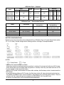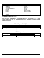
1
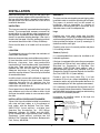
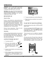
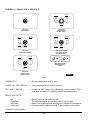
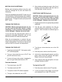
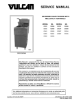
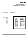
INSTALLATION &
OPERATION MANUAL
GR SERIES GAS FRYERS
MODELS:
GRS25
GRS35
GRS45
GRS65
GRS85
GRD25
GRD35
GRD45
GRD65
GRD85
GRD35
VULCAN-HART
COMPANY,
FORM 30748, Rev. B (1-98)
P.O.
BOX
696,
LOUISVILLE,
KY
40201-0696,
GRS65
TEL. (502) 7 7 8 - 2 7 9 1
IMPORTANT SAFETY INFORMATION
THIS MANUAL HAS BEEN PREPARED FOR PERSONNEL QUALIFIED TO INSTALL GAS EQUIPMENT,
WHO SHOULD PERFORM THE INITIAL FIELD START-UP AND ADJUSTMENTS OF THE EQUIPMENT
COVERED BY THIS MANUAL.
POST IN A PROMINENT LOCATION THE INSTRUCTIONS TO BE FOLLOWED IN THE EVENT THE SMELL
OF GAS IS DETECTED. THIS INFORMATION CAN BE OBTAINED FROM THE LOCAL GAS SUPPLIER.
IMPORTANT
IN THE EVENT A GAS ODOR IS DETECTED, SHUT
DOWN UNITS AT MAIN SHUT-OFF VALVE AND
CONTACT THE LOCAL GAS COMPANY OR GAS
SUPPLIER FOR SERVICE.
FOR YOUR SAFETY
DO NOT STORE OR USE GASOLINE OR OTHER
FLAMMABLE VAPORS OR LIQUIDS IN THE
VICINITY OF THIS OR ANY OTHER APPLIANCE.
IN THE EVENT OF A POWER FAILURE, DO NOT
ATTEMPT TO OPERATE THIS DEVICE.
WARNING: IMPROPER INSTALLATION, ADJUSTMENT, ALTERATION,
SERVICE OR MAINTENANCE CAN CAUSE PROPERTY DAMAGE, INJURY
OR DEATH. READ THE INSTALLATION, OPERATING, AND
MAINTENANCE INSTRUCTIONS THOROUGHLY BEFORE INSTALLING
OR SERVICING THIS EQUIPMENT.
2
TABLE OF CONTENTS
GENERAL. . . . . . . . . . . . . . . . . . . . . . . . . . . . . . . . . . . . . . . . . . . . . . . . . . . . . . . . . . . . . . . . . . . . . . . .
GR Series Gas Fryers . . . . . . . . . . . . . . . . . . . . . . . . . . . . . . . . . . . . . . . . . . . . . . . . . . . . . . .
Finish Options . . . . . . . . . . . . . . . . . . . . . . . . . . . . . . . . . . . . . . . . . . . . . . . . . . . . . . . . .
Features, Construction Features, Battery Configurations . . . . . . . . . . . . . . . . . . . . . . .
Field Installable Accessories, Factory Installed Only . . . . . . . . . . . . . . . . . . . . . . . . . .
GR Series Frymate (Dump Station) . . . . . . . . . . . . . . . . . . . . . . . . . . . . . . . . . . . . . . . . . . . . .
Finish Options, Features . . . . . . . . . . . . . . . . . . . . . . . . . . . . . . . . . . . . . . . . . . . . . . . . .
4
4
4
5
6
6
6
INSTALLATION . . . . . . . . . . . . . . . . . . . . . . . . . . . . . . . . . . . . . . . . . . . . . . . . . . . . . . . . . . . . . . . . . . .
Uncrating . . . . . . . . . . . . . . . . . . . . . . . . . . . . . . . . . . . . . . . . . . . . . . . . . . . . . . . . . . . . . . . . . .
Location . . . . . . . . . . . . . . . . . . . . . . . . . . . . . . . . . . . . . . . . . . . . . . . . . . . . . . . . . . . . . . . . . . .
Installation Codes and Standards . . . . . . . . . . . . . . . . . . . . . . . . . . . . . . . . . . . . . . . . . . . . . .
Assembly . . . . . . . . . . . . . . . . . . . . . . . . . . . . . . . . . . . . . . . . . . . . . . . . . . . . . . . . . . . . . . . . . .
Legs . . . . . . . . . . . . . . . . . . . . . . . . . . . . . . . . . . . . . . . . . . . . . . . . . . . . . . . . . . . . . . . . .
Casters (Optional) . . . . . . . . . . . . . . . . . . . . . . . . . . . . . . . . . . . . . . . . . . . . . . . . . . . . . .
Gas Connections . . . . . . . . . . . . . . . . . . . . . . . . . . . . . . . . . . . . . . . . . . . . . . . . . . . . . . . . . . .
Gas Pressures and Orifices . . . . . . . . . . . . . . . . . . . . . . . . . . . . . . . . . . . . . . . . . . . . . . . . . . .
Testing the Gas Supply Piping System . . . . . . . . . . . . . . . . . . . . . . . . . . . . . . . . . . . . . . . . . .
Leveling the Fryer . . . . . . . . . . . . . . . . . . . . . . . . . . . . . . . . . . . . . . . . . . . . . . . . . . . . . . . . . . .
Flue Connections . . . . . . . . . . . . . . . . . . . . . . . . . . . . . . . . . . . . . . . . . . . . . . . . . . . . . . . . . . .
Electrical Connections . . . . . . . . . . . . . . . . . . . . . . . . . . . . . . . . . . . . . . . . . . . . . . . . . . . . . . .
7
7
7
7
7
7
7
8
8
8
8
8
8
OPERATION . . . . . . . . . . . . . . . . . . . . . . . . . . . . . . . . . . . . . . . . . . . . . . . . . . . . . . . . . . . . . . . . . . . . . 9
Before First Use . . . . . . . . . . . . . . . . . . . . . . . . . . . . . . . . . . . . . . . . . . . . . . . . . . . . . . . . . . . . 9
Lighting the Manual Gas Pilot . . . . . . . . . . . . . . . . . . . . . . . . . . . . . . . . . . . . . . . . . . . . . . . . . 9
Filling the Fry Tank with Shortening . . . . . . . . . . . . . . . . . . . . . . . . . . . . . . . . . . . . . . . . . . . . 9
Controls . . . . . . . . . . . . . . . . . . . . . . . . . . . . . . . . . . . . . . . . . . . . . . . . . . . . . . . . . . . . . . . . . . 10
Melting Solid Shortening . . . . . . . . . . . . . . . . . . . . . . . . . . . . . . . . . . . . . . . . . . . . . . . . . . . . 11
Turning the Fryer On . . . . . . . . . . . . . . . . . . . . . . . . . . . . . . . . . . . . . . . . . . . . . . . . . . . . . . . 11
Turning the Fryer Off . . . . . . . . . . . . . . . . . . . . . . . . . . . . . . . . . . . . . . . . . . . . . . . . . . . . . . . 11
Electronic Igniter (Optional) . . . . . . . . . . . . . . . . . . . . . . . . . . . . . . . . . . . . . . . . . . . . . . . . . . 11
Frying (All Models) . . . . . . . . . . . . . . . . . . . . . . . . . . . . . . . . . . . . . . . . . . . . . . . . . . . . . . . . . 12
Daily (All Models) . . . . . . . . . . . . . . . . . . . . . . . . . . . . . . . . . . . . . . . . . . . . . . . . . . . . . . . . . . 12
Daily Filtering . . . . . . . . . . . . . . . . . . . . . . . . . . . . . . . . . . . . . . . . . . . . . . . . . . . . . . . . . . . . . 12
Fryers Without Filter Ready Options . . . . . . . . . . . . . . . . . . . . . . . . . . . . . . . . . . . . . . 12
Filtering Procedure (Not Filter Ready) . . . . . . . . . . . . . . . . . . . . . . . . . . . . . . . . . . . . . 13
Filter-Ready Fryers Only . . . . . . . . . . . . . . . . . . . . . . . . . . . . . . . . . . . . . . . . . . . . . . . . 13
Battery Interplumbing (Optional) . . . . . . . . . . . . . . . . . . . . . . . . . . . . . . . . . . . . . . . . . . 13
Shortening Life (All Models) . . . . . . . . . . . . . . . . . . . . . . . . . . . . . . . . . . . . . . . . . . . . . . . . . . 13
High Limit Device (All Models) . . . . . . . . . . . . . . . . . . . . . . . . . . . . . . . . . . . . . . . . . . . . . . . . 13
Cleaning (All Models) . . . . . . . . . . . . . . . . . . . . . . . . . . . . . . . . . . . . . . . . . . . . . . . . . . . . . . . 14
MAINTENANCE . . . . . . . . . . . . . . . . . . . . . . . . . . . . . . . . . . . . . . . . . . . . . . . . . . . . . . . . . . . . . . . . . .
Lubrication . . . . . . . . . . . . . . . . . . . . . . . . . . . . . . . . . . . . . . . . . . . . . . . . . . . . . . . . . . . . . . . .
Vent . . . . . . . . . . . . . . . . . . . . . . . . . . . . . . . . . . . . . . . . . . . . . . . . . . . . . . . . . . . . . . . . . . . .
Service and Parts Information . . . . . . . . . . . . . . . . . . . . . . . . . . . . . . . . . . . . . . . . . . . . . . . .
3
15
15
15
15
INSTALLATION AND OPERATION MANUAL
FOR GR SERIES GAS FRYERS
KEEP THESE INSTRUCTIONS FOR FUTURE USE
GENERAL
Vulcan-Hart GR Series Gas Fryers are available in
5 sizes with an array of features and options for a
range of commercial fryer applications. While the
overall tank width on the GR35 and GR45 are the
same, the GR45 has a deeper tank area than GR35.
Thus the GR45 has larger tank capacity than GR35
but not as large as GR65. Likewise the GR65 and
GR85 are the same width, but the GR85 with a
deeper tank area has a larger tank capacity than the
GR65. Each gas burner tube has 30,000 BTU input
rating.
Model
No.
Tubes
BTU
Input
Width
Lb. of Fry
Compound
GRS25, GRD25
2
60,000
101⁄2"
25-30
GRS35, GRD35
3
90,000
151⁄2"
35-40
GRS45, GRD45
4
120,000
151⁄2"
45-50
GRS65, GRD65
5
150,000
21"
65-70
GRS85, GRD85
5
150,000
21"
70-85
GR Series Fryers can be free standing (except for
GRS25 and GRD25) or arranged in batteries of 2 to
5 units. The number preceding the model number of
your GRS or GRD Series Fryer refers to the number
of units in a battery. One unit in a battery can be a
Frymate Dump Station (only one per battery).
GRS Fryers have a mechanical thermostat and GRD
Fryers have a solid state thermostat. GRC Fryers,
while part of the GR Series, are covered in a separate
manual.
Feature options include Fat Melt (standard on GRD);
Basket Lift(s) with Timer(s); Tri, Twin, or Single
Baskets; Pilot or Electronic Igniter; Filter Ready (except
GRS25 and GRD25); and Battery Interplumbing.
Finish options include: S/S Sides and Flue; S/S Tank;
and Casters. S/S Legs are standard.
Your Vulcan Fryer is constructed and designed to
give long satisfactory service, providing it is properly
installed, adjusted and maintained.
The Mobile Filter is covered under separate Installation
and Operation Manual.
GR Series Fryer — Finish Options
All Models
Front Door
Standard
Stainless Steel
Optional
Not Applicable
Ext. Sides & Flue
Tank
Legs
Painted Steel
Carbon Steel
Stainless Steel Legs
Stainless Steel
Stainless Steel
Casters
4
GR Series Fryer — Features
Model
Pilot
Igniter
Electronic
Fat Melt
Cycle
Thermostat
Basket Lift(s)
Basket(s)
Twin Single
Tri
GRS25,
GRS35, GRS45,
GRS65, GRS85
Std.
Opt.
Opt.
Mechanical
Opt.
N/A
Std.
Std.
Std.
Opt.
Opt.
N/A
N/A
Opt.
GRD25,
GRD35, GRD45,
GRD65, GRD85
Std.
Opt.
Std.
Solid State
Opt.
N/A
Std.
Std.
Std.
Opt.
Opt.
N/A
N/A
Opt.
GR Series Fryer — Construction Features
Model
Filter Ready
Battery
Configuration
Battery
Interplumbing
GRS25, GRD25
Mobile Filter Not Available
Std.
Opt. with GR35, GR45,
GR65, GR85, R015 or R021
GRS35, GRD35
Opt. (Use MF50.)
Opt.
Opt.
GRS45, GRD45
Opt. (Use MF50.)
Opt.
Opt.
GRS65, GRD65
Opt. (Use MF85.)
Opt.
Opt.
GRS85, GRD85
Opt. (Use MF85.)
Opt.
Opt.
BATTERY CONFIGURATIONS
Batteries of up to five units wide can be configured with any GR Series Fryer or Frymate Dump Station (either
151⁄2" or 21" wide). Possible configurations showing positions A through E are depicted below:
A
A B
A B C
A B C D
A B C D E
NOTES:
= Dump Station;
= Fryer.
* Indicates filter interplumbing not available.
A filter dump station can be located under any position in a battery if it has been built without an RO Frymate.
A filter dump station can be located under any position in a battery if the line-up has been built with an RO
Frymate located at either end of the battery.
When an RO Frymate is built between two fryers within a battery, the filter dump station is located under the
RO Frymate.
In two-unit batteries utilizing an RO Frymate, the filter dump station will always be located under the fryer.
The GRS25 and GRD25 Fryers are not available as stand alone fryers or with filter dump stations. They are
available with filter interplumbing when batteried with GRS/GRD35, 45, 65 and 85 Fryers.
All options and accessories can be used with batteried equipment.
5
Field Installable Accessories
Factory Installed Only
Casters
Twin Baskets
Single Baskets
Tri Baskets (GR65/GR85 only)
Heat Lamp
Flex Hose 4'
Flex Hose 5'
S/S Vat Cover
Batter Tray
Tank Skimmer
Tank Scoop
Electronic Pilot
Fat Melt
Basket Lift
S/S Tank
S/S Sides
Battery Configuration
Battery Interplumbing
GR SERIES FRYMATE (Dump Station)
Model RO Frymate Dump Station can be configured in batteries with fryers in either 151⁄2" or 21" width.
Frymate provides a final prep area where excess oil drains away and product is seasoned, packaged,
and kept ready for sale.
RO Series Frymate — Finish Options
Model RO15, RO21, RO21S*
Front Door
Sides & Dummy Flue
Legs
Standard
Optional
Stainless Steel
Painted Steel
Stainless Steel Legs
Not Applicable
Stainless Steel
Casters
*Model RO15 is for use with all GR25, GR35 and GR45 Series Fryers.
Model RO21 is for use with all GR65 Series Fryers.
Model RO21S is for use with all GR85 Series Fryers.
RO Series Frymate — Features
Heat Lamp
Opt.
Tops
Drain
Solid
Pan Solid
Pan Perforated
Std.
Opt.
Opt.
Opt.
* Side liners are not available in batteries with RO interplumbed Frymates.
6
Side Liners*
Opt.
INSTALLATION
ASSEMBLY
Before installing the fryer, verify that the type of gas
(natural or propane) agrees with the specifications on
the fryer data plate which is located on the inside of
the door panel. Also be sure the unit is built for the
installation elevation.
The fryer must be restrained to prevent tipping when
installed in order to avoid the splashing of hot liquid.
The means of restraint may be the manner of
installation, such as connection to a battery of
appliances or installing the fryer in an alcove, or by
separate means, such as adequate ties.
UNCRATING
This fryer was carefully inspected before leaving the
factory. The transportation company assumes full
responsibility for safe delivery upon acceptance of
the shipment. Immediately after unpacking the fryer,
check it for possible shipping damage. If the fryer is
found to be damaged, save the packaging material
and contact the carrier within 15 days of delivery.
Legs
Position fryer in an open space near the final
installation area. Tilt fryer on its side, being careful to
avoid scratching the finish. Thread legs into mounting
holes provided on bottom of fryer by screwing in a
clockwise rotation until tight.
Do not use the door or its handle to lift or move the
fryer.
Carefully raise fryer to its normal position and place
it in installing location.
LOCATION
Casters (Optional)
The equipment area must be kept free and clear of
combustible substances.
It is recommended that casters be installed on all
batteried appliances.
Minimum clearance from combustible construction is
6" from the sides and 6" from the back of the fryer.
Minimum clearance from non-combustible
construction is 0" from the sides and 6" from the back
of the fryer. There must be at least 16" clearance
between the fryer and any open top flame units.
Adequate clearances for servicing and proper
operation must be allowed. The unit may be installed
on combustible floors.
If the fryer is equipped with casters the gas connector
(available from Vulcan-Hart) must comply with the
Standard for Connectors of Movable Gas
Appliances, ANSI-Z21.69 (latest edition), and a
quick-disconnect device that complies with the
Standard for Quick-Disconnect Devices for Use With
Gas Fuel, ANSI-Z21.41 (latest edition).
Provide a gas line strain relief (Fig. 1) to limit
movement of the fryer without depending on the
connector and/or any quick-disconnect device or its
associated piping to limit the appliance movement.
Install the fryer in an area with sufficient air supply for
combustion of the gas at the fryer burners. Provide
adequate clearance for air openings into the
combustion chamber. Do not obstruct the flow of
combustion and ventilation air.
If it is necessary to disconnect the restraint, turn off
the gas supply before disconnection. Reconnect the
restraint before turning the gas supply on and returning
the unit to its installation position.
Do not permit fans to blow directly at the fryer. Avoid
open windows next to the unit sides or back. Avoid
wall-type fans which create air cross currents within
the room.
Instructions for installing casters to the fryer are
included with the casters.
INSTALLATION CODES AND STANDARDS
STRAIN RELIEF
FITTING FOR GAS LINE
THIS SIDE ONLY.
(Strain relief fitting
supplied by Vulcan-Hart.
Chain to be supplied by
others.)
Vulcan-Hart fryers should be installed in accordance
with state and local codes, or in the absence of
local codes, with the National Fuel Gas Code,
ANSI-Z223.1 (latest edition), available from
American Gas Association, Inc., 1515 Wilson
Boulevard, Arlington, VA 22209, and with ANSINFPA Standard #96, Vapor Removal from Cooking
Equipment, (latest edition) available from the
National Fire Protection Association, Batterymarch
Park, Quincy, MA 02269.
PL-51493
Fig. 1
7
GAS CONNECTIONS
FLUE CONNECTIONS
CAUTION: All gas supply connections and any
pipe joint compound must be resistant to the
action of propane gases.
The fryer must be located under a hood which has
an adequate connection to an exhaust duct. The
hood must extend 6" beyond fryer sides.
The gas inlet is located at the lower right rear. Codes
require that a gas shutoff valve be installed in the gas
line ahead of the fryer.
Adequate ventilation must be provided and must
comply with NFPA Standard #96, (latest edition),
and with local codes.
Clearance above fryer should be adequate for
products of combustion to be removed efficiently.
An 18" minimum clearance should be maintained
between the flue vent and the filters of the hood
venting system.
The gas supply line must be at least the equivalent of
1
⁄2" iron pipe. If using the optional quick-disconnect
flex hose, 3⁄4" iron pipe must be used unless 3⁄4" to
1
⁄2" reducing fittings are used. Make sure the pipes
are clean and free of obstructions, dirt, and
piping compound. A battery requires one or two
connections of appropriate size and type for the
gas requirement.
Never make flue connections directly to the fryer.
Do not obstruct the flow of the flue gases from the
flue duct located at the rear of the appliance.
WARNING: PRIOR TO LIGHTING, CHECK ALL
JOINTS IN THE GAS SUPPLY LINE FOR LEAKS.
USE SOAP AND WATER SOLUTION. DO NOT USE
AN OPEN FLAME.
Adequate air should be provided in the kitchen to
replace air taken out by the ventilating system.
This will prevent fryer function from being affected
by a reduced atmospheric pressure.
After piping has been checked for leaks, fully purge
gas pipes to remove air.
ELECTRICAL CONNECTIONS
WARNING: ELECTRICAL AND GROUNDING
CONNECTIONS MUST COMPLY WITH THE
NATIONAL ELECTRICAL CODE, ANSI/NFPA 70
OR THE CANADIAN ELECTRICAL CODE, CSA
C22.2 AND/OR OTHER LOCAL CODES.
GAS PRESSURES AND ORIFICES
The standard orifices are set at 4" W.C. (Water
Column) pressure for natural gas and 10" W.C.
(Water Column) pressure for propane gas. A
pressure regulator is supplied as part of the gas
control valve.
When test pressures exceed 1⁄2 psig (3.45 kPa),
the fryer and its individual shutoff valve must be
disconnected from the gas supply piping system.
WARNING: APPLIANCES EQUIPPED WITH
ELECTRICAL SUPPLY CORD(S) ARE PROVIDED
WITH A THREE-PRONG GROUNDING PLUG
WHICH MUST BE CONNECTED TO A PROPERLY
GROUNDED RECEPTACLE. IF THE RECEPTACLE
IS NOT THE PROPER GROUNDING TYPE,
CONTACT AN ELECTRICIAN. DO NOT REMOVE
THE GROUNDING PRONG FROM THE PLUG.
When test pressures are 1⁄2 psig (3.45 kPa) or
less, the fryer must be isolated from the gas
supply piping system by closing its individual
shutoff valve.
Some fryers (depending on options) are equipped
with a 120 Volt/60 Hz./1 Phase cord and plug
which requires only that it be plugged into a
properly grounded 120 volt receptacle.
LEVELING THE FRYER
Do not connect fryer to electrical supply until after
gas connections have been made.
TESTING THE GAS SUPPLY PIPING SYSTEM
Once gas connections have been made, place a
spirit level on top of the fryer. Adjust the legs to
ensure that the fryer is level front-to-back and
side-to-side in the final installed position.
8
OPERATION
WARNING: HOT OIL AND PARTS CAN CAUSE
BURNS. USE CARE WHEN OPERATING,
CLEANING AND SERVICING THE FRYER.
WARNING: SPILLING HOT FRYING COMPOUND
CAN CAUSE SEVERE BURNS. DO NOT MOVE
FRYER WITHOUT DRAINING ALL FRYING
COMPOUND FROM THE TANK.
Fig. 3
BEFORE FIRST USE
5. Turn gas valve extension arm to the ON position.
Clean the Fryer
6. Repeat the above procedures if gas supply is
interrupted.
Using a non-corrosive, grease-dissolving
commercial cleaner, clean the protective metal oils
from all surface parts and the tank interior. Follow
the cleaner manufacturer's directions. Rinse
thoroughly and drain by opening the drain valve
accessible when the door is opened. Wipe tank
completely dry with a soft clean cloth.
FILLING THE FRY TANK WITH SHORTENING
Liquid shortening may be used in all GRS and GRD
Series Fryers.
Only fryers equipped with the MELT cycle may use
solid shortening. The melt cycle MUST be used if
using solid shortening. (See MELTING SOLID
SHORTENING in this manual.)
Clean all fryer accessories. Rinse all parts
thoroughly after cleaning and wipe dry.
Seasoning
Tank warranty may be voided by improper
operation. Turn gas valve off when draining or
filling.
Light seasoning of the backsplash area is required
to avoid possible surface corrosion. With a soft,
lint-free cloth, apply a thin layer of cooking oil over
the entire backsplash area. This should also be
done after every cleaning.
Fill fryer tank to the "fill level" line on back wall
about three inches above the tank tubes (Fig. 4).
Keep shortening at "fill level" line in fry tank. Add
fresh shortening as needed. Do not overfill tank.
LIGHTING THE MANUAL GAS PILOT
1. Turn thermostat OFF.
F
OF
OT
2. Push gas valve extension
arm in and turn arm to the
OFF position (Fig. 2). Wait 5
minutes for unburned gas to
vent.
PIL
ON
PL-50579
- FILL LEVEL -
Fig. 2
3. Push gas valve extension arm in and turn to the
PILOT position.
COLD ZONE
4. While still depressing arm, light the pilot with a
lit taper (Fig. 3). Continue with Steps 2, 3, and
4 until pilot remains lit when extension arm is
released.
PL-51491
Fig. 4
9
CONTROLS — Models GRS or GRD (Fig. 5)
HIGH LIMIT
ON
P
FRY
O
W
E
R
OFF
MELT
HEATING
GRD FRYER
MANUAL PILOT
FRY-MELT SWITCH
GRS FRYER
MANUAL PILOT
HIGH LIMIT
P
O
W
E
R
HIGH LIMIT
ON
ON
P
O
W
E
R
OFF
OFF
HEATING
MELT
HEATING
TROUBLE
TROUBLE
GRD OR GRS FRYER
ELECTRONIC IGNITER
FRY-MELT SWITCH
GRS FRYER
ELECTRONIC IGNITER
15 MIN. TIMER
0
HIGH LIMIT
1
2
3
4
15
14
P
O
W
E
R
FRY
5
6
13
12
FRY
ON
15 MIN. TIMER
PUSH TO
TIME
11
10 9
8
7
0
2
3
4
PUSH TO
TIME
5
6
13
12
BASKET LIFT CONTROL
11
10 9
8
7
BASKET LIFT CONTROL
GRD OR GRS FRYER
TIMED BASKETLIFT
OPTION
MELT
OFF
1
15
14
HEATING
GRS FRYER
MANUAL PILOT
FRY-MELT SWITCH
PL-51432
Fig. 5
THERMOSTAT
— Controls temperature of oil in tank.
POWER ON - OFF* SWITCH
— Turns electric power to the fryer on or off.
FRY - MELT* SWITCH
— Position on MELT when solid shortening is being melted; FRY is
used after shortening is liquified to reach frying temperatures.
INDICATOR LIGHTS*
ON
TROUBLE
HEATING
HIGH LIMIT
—
—
—
—
Electric power to the machine is on.
The electronic igniter has not been able to light the pilot.
Burners are supplying heat, warming oil in tank per the thermostat.
Oil temperature is higher than 465°F and system has shut down.
* Present on some models.
10
MELTING SOLID SHORTENING
5. After draining and cleaning, apply a thin film of
cooking oil to tank interior and tank back to
avoid possible surface corrosion.
Melting solid shortening without using the melt
cycle will damage the fry tank and scorch the
shortening.
ELECTRONIC IGNITER (Optional)
Only fryers equipped with the MELT cycle may use
solid shortening. Solid shortening must be gently
warmed to the liquid state before heating to frying
temperatures. To begin the melt cycle, press the
MELT switch.
CAUTION: Before turning the burners on, the
fry tank must be filled with liquid or melted
shortening. If this is not done, the tank walls
can be damaged. Warpage can cause leaks.
TURNING THE FRYER ON
1. Plug the power cord to an appropriate grounded
receptacle.
CAUTION: Before turning the burners on, the
fry tank must be filled with liquid or melted
shortening. If this is not done, the tank walls
can be damaged. Warpage can cause leaks.
2. Turn the gas valve extension arm (Fig. 6)
(located inside the cabinet door) to the OFF
position. Wait 5 minutes for unburned gas to
vent.
To turn the fryer ON, plug the power cord to an
appropriate grounded receptacle and set the
thermostat knob to the desired temperature.
F
OF
When the set temperature is reached, the gas
control shuts off gas flow into the burners and the
flame is extinguished. From then on, the fryer will
cycle on and off to maintain set temperature.
ON
PL-50578
Fig. 6
3. Turn the gas valve extension arm to the ON
position.
TURNING THE FRYER OFF
1. Turn thermostat knob OFF. Push power switch
OFF (when equipped).
4. Push the power switch to the ON position.
5. If pilot fails to light within 90 seconds, push the
power switch to the OFF position and repeat
Steps 3 and 4 until the pilot lights.
2. Turn gas valve extension arm to PILOT (the
pilot will continue to burn).
3. To shut off all gas to the system, including the
pilot, turn gas valve extension arm OFF.
6. Thirty seconds after the pilot ignites, the fryer
will begin heating to 350°F.
Extended Shutdown
1. Turn manual gas valve OFF.
Turning the Fryer OFF
2. Turn thermostat knob OFF.
1. Push the power switch to the OFF position.
3. Turn power switch OFF (when equipped).
2. To shut off all gas to the system, turn the gas
valve extension arm to the OFF position.
4. Turn gas valve extension arm to OFF.
11
Batter-covered foods should be dropped carefully,
one by one, into shortening or basket. If you use
the basket, first dip basket into shortening to
reduce batter build-up on basket surfaces.
Extended Shutdown
1. Turn manual gas shutoff valve OFF.
2. Push the power switch to the OFF position and
unplug the fryer.
Corn-on-the-cob must be submerged to fry
uniformly. Place corn in bottom of basket. Stack
an empty basket on top of corn to keep it submerged.
3. Turn gas valve extension arm to the OFF
position.
When frying is completed, remove baskets or
product. Hang baskets on rear basket hangers.
Remove food and season it. Do not salt food over
the shortening because salt could cause a chemical
change in the oil.
4. Apply a thin coat of cooking oil to tank interior
and tank back to prevent rust.
FRYING (All Models)
DAILY (All Models)
Heat shortening to set temperature.
Add approximately 15% new shortening daily. Keep
level of shortening at "fill level" line in fry tank. Add
fresh shortening as needed.
Pieces of product to be fried should be about the
same size to ensure the same doneness.
DAILY FILTERING
Drain or wipe dry raw or wet foods to minimize
splatter when lowering into the hot oil.
Fryers Without Filter Ready Options
Do not overfill baskets.
Turn gas valve off when draining or filling.
Recommended maximum capacities are:
Models
Lb. of
Product
(1 Basket)
Total Lb.
of Product
(2 Baskets)
Total Lb.
of Product
(3 Baskets)
GR25
1 1/ 2
N/A
N/A
GR35
1 1/ 2
3
N/A
GR45
2 1/ 2
5
N/A
GR65
3
6
9
GR85
3 1/ 2
7
101/2
Always filter the shortening while liquified. A cold
fryer will not drain properly because the shortening
under the cold zone tube area will remain hard,
even if the heat is on for a few minutes. If necessary,
the clean-out rod may be used to carefully stir up
hard fat to an area above the cold zone (see Fig. 4)
where it will melt. After the cold zone is liquified,
turn the fryer thermostat and gas valve off.
Shortening life will be extended by filtering at least
once a day or more often if conditions warrant. A
commercial power filter (available from other
manufacturers) may be used. Follow the
manufacturer's operating instructions for draining,
straining, and replacing shortening in the fry tank.
Carefully lower baskets into oil.
When frying doughnuts and fritters, turn product
only once during frying.
Another way to filter is to drain the shortening from
the drain pipe through a filter bag, or cover the
receiving container with cheesecloth or other
filtering material.
When cooking French fries or onion rings, shake
basket several times in a way that does not splatter
the shortening.
12
Filtering Procedure (Not Filter Ready)
Always be sure you have adequate container
capacity before opening drain; monitor draining
process.
1. Turn the fryer off.
2. Slowly remove the baskets, especially if
shortening is hot, to prevent splashing.
After oil has filtered into the mobile filter, it is
pumped back to the individual tank by (1) closing
the drain valve, and (2) opening the valve on the
return line (Fig. 7). Only one return valve should be
opened at any one time.
3. Open the fryer door and attach the drain pipe to
the drain valve.
4. Select a container of sufficient capacity and
place it below the drain pipe.
After oil is pumped back, close the return valve. Fill
tank to the "fill level" line on the back wall of the fry
tank.
5. If you are using a filter bag, tie it securely to the
drain pipe. If other filter medium is used, place
it in the container.
6. Open the drain valve carefully so the oil stream
is directed through the filter.
7. With a small amount of warm shortening, flush
out scraps and sediment in the fry tank. Drain
the tank thoroughly and wipe clean.
Fig. 7
8. Should it be necessary to clean the tank more
thoroughly, follow the procedure shown in
CLEANING — WEEKLY OR AS REQUIRED in
this manual.
SHORTENING LIFE (All Models)
Shortening life may be extended by following these
guidelines:
9. Close the drain valve.
•
•
•
•
10. Pour strained shortening back into the tank.
11. Add shortening to the "fill level" line.
•
•
•
Filter-Ready Fryers Only
Follow instructions in the MOBILE FILTER
OPERATING MANUAL shipped with the mobile
filter. If the manual is not found, contact your
dealer to obtain the manual before operating the
mobile filter.
Do not salt foods over the fryer.
Use good quality shortening.
Filter shortening daily at a minimum.
Replace shortening if it becomes poorly
flavored.
Keep equipment and surroundings clean.
Set thermostats correctly.
Remove excess moisture and particles from
food products before placing in fryer.
HIGH LIMIT DEVICE (All Models)
If the shortening becomes overheated, a high
temperature shutoff device will turn the gas valve
off and extinguish the pilot. DO NOT relight the
pilot until the shortening temperature is below
300°F. If this situation persists, contact your local
Vulcan-Hart authorized service office.
Battery Interplumbing (Optional)
A battery of fryers equipped with optional
interplumbing connects the fry tanks to a common
drain. Each tank has an individual drain valve;
these should only be opened one at a time.
13
2. Close the drain valve and fill the tank with a
non-corrosive, grease-dissolving commercial
cleaner, following the manufacturer's
instructions.
CLEANING (All Models)
WARNING: DISCONNECT ELECTRICAL POWER
SUPPLY BEFORE CLEANING.
3. Set the thermostat at a temperature
recommended by the manufacturer of the
commercial cleaner and boil the solution for 15
to 20 minutes. If cleaner is a water based
chemical, temperature may be 190 - 212°F.
Set the temperature as low as possible; monitor
boiling to prevent overflow.
Daily
Clean the exterior of your fryer regularly with a
damp cloth and polish with a soft dry cloth. If
regular cleaning is neglected, grease will be burned
on and discolorations may form. These may be
removed by washing with any detergent or soap
and water. A self-soaping scouring pad may be
used for particularly stubborn discolorations.
Always rub with the "GRAIN" in a horizontal
direction.
4. Drain the cleaning solution from the tank.
5. Close the drain valve and refill the tank with
water. Add 1 cup of vinegar to neutralize
alkaline left by the cleaner. Bring the solution
to a boil and allow it to stand for a few minutes.
Keeping the fryer exterior clean and free of
accumulated grease will prevent stubborn stains
from forming. Wash all exterior surfaces at least
once daily. Use a cloth with warm water and a mild
soap or detergent. Follow with a clear rinse, then
dry.
6. Drain the tank and rinse thoroughly with clear
hot water. All traces of cleaner must be
removed. Dry the tank thoroughly.
Fingerprints are sometimes a problem on highly
polished surfaces of stainless steel. They can be
minimized by applying a cleaner that will leave a
thin oily or waxy film.
7. Close the drain valve.
Weekly or as Required
The fryer is now ready for use.
8. Add shortening the the "fill level" line in the fry
tank.
1. Once the shortening has been drained, flush
out scraps and sediment with a small amount of
warm shortening. Allow the tank to drain
thoroughly.
14
MAINTENANCE
WARNING: HOT OIL AND PARTS CAN CAUSE
BURNS. USE CARE WHEN OPERATING,
CLEANING AND SERVICING THE FRYER.
VENT
Annually, when fryer is cool, check the flue and
clear any obstructions.
WARNING: SPILLING HOT FRYING COMPOUND
CAN CAUSE SEVERE BURNS. DO NOT MOVE
FRYER WITHOUT DRAINING ALL FRYING
COMPOUND FROM THE TANK.
SERVICE AND PARTS INFORMATION
To obtain service and parts information concerning
this fryer, contact the Vulcan-Hart Service Depot in
your area (refer to listing supplied with the fryer), or
Vulcan-Hart Company Service Department at the
address or phone number shown on the front cover
of this manual.
LUBRICATION
Motors used on basketlifts are permanently
lubricated.
15
NOTES
FORM 30748, Rev. B (1-98)
16
PRINTED IN U.S.A.