1
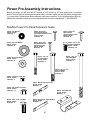
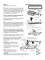
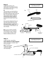
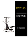
®
BOWFLEX
Power Pro
ASSEMBLY
MANUAL
Includes Instructions
for Bowflex Power Pro
Attachments and
Upgrades.
Please Keep for Your Records
Warranties Do Not Cover
What Is Covered
Bowflex, Inc. warrants to the original purchaser of the Bowflex® home
fitness machine to be free from defects in materials or workmanship,
with the exceptions stated below. This warranty is not transferable
or applicable to any person other than the original purchaser.
Bowflex Power Pro
The Bowflex patented Power Rod resistance is covered by a
No-Time-Limit Warranty. The Bowflex Power Pro is warrantied
to the original purchaser for five (5) years. This five year warranty
covers all defects in material or workmanship of the Bowflex
Power Pro. The warranty does not cover commercial use or
misuse & abuse by the consumer. To make this warranty
effective, you must completely fill out the owner registration
card and return it to Bowflex, 1400 NE 136th Ave. Vancouver,
WA 98684 within thirty (30) days of your purchase of the Bowflex.
Bowflex Motivator
The Bowflex patented Power Rod resistance is covered by a
No-Time-Limit Warranty. The Bowflex Motivator is warrantied
to the original purchaser for two (2) years. This two year warranty
covers all defects in material or workmanship of the Bowflex
Motivator except for the vinyl covering on the bench. The vinyl
covering on the bench is warrantied for 90 days. The warranty
does not cover commercial use or misuse & abuse by the
consumer. To make this warranty effective, you must completely
fill out the owner registration card and return it to Bowflex, 1400
NE 136th Ave. Vancouver, WA 98684 within thirty (30) days of
your purchase of the Bowflex.
• A Bowflex purchased for commercial or institutional use.
• Damage due to use by persons who weigh more than 300 pounds.
• Damage due to abuse, misuse, accident or acts of God (such as
floods).
• Consequential or incidental damages.
Some states do not allow the exclusion or limitation of incidental or
consequential damages, so the above limitation or exclusion may not
apply to you.
What We Will Do
Bowflex, Inc. will repair any Bowflex that proves to be a defect in materials
or workmanship. In the event repair is not possible, Bowflex, Inc. at its
option, will either replace your Bowflex or refund your purchase price.
How To Get Service
Simply return the defective part at your expense to Bowflex, Inc. at 1400
NE 136 th Ave. Vancouver, WA 98661 with an explanation of the problem.
For information, you may contact a service representative at 1-800-2693539 or write us at the above address, Attention Warranty. Adequate
protective packaging of the defective parts or unit and cost of shipping
to the above address are your responsibility. The repaired part or unit
will be returned to you at the company's expense.
How State Law Applies
This warranty gives you specific legal rights, and you may also have
other rights which vary from state to state.
Table of Contents
Bowflex Power Pro ................................................... 4-10
Part Reference and Size Guide ................................ 4
PowerPro Reference Guide ...................................... 5
Assembly Instructions ............................................... 6-10
Leg Extension Attachment ...................................... 11-13
Part Reference and Size Guide ................................ 11
Assembly Instructions ............................................... 12-13
Chest Bar Attachment .............................................. 14-17
Assembly Instructions ............................................... 15-17
Lat Pulldown Attachment ......................................... 18-22
Part Reference and Size Guide ................................ 18
Assembly Instructions ............................................... 19-22
Squat Attachment ..................................................... 23-24
Assembly Instructions ............................................... 23
Exercise Instructions ................................................. 23-24
Foot Harness Attachment ........................................ 25-26
Assembly Instructions ............................................... 25-26
Additional Power Rods ............................................ 27
Assembly Instructions ............................................... 27
Please check to make sure all parts are included. If you are missing any
part, please call a customer service representative at 1-800-269-3539.
Power Pro Assembly Instructions
Before you begin, you will need a 9/16" wrench, a 7/16" wrench, a 1/2" open end wrench, a crescent
wrench (to hold the bolt while tightening with other), a rubber mallet (for step #5) and a phillips head
(+) screw driver. Please follow these assembly instructions carefully. If you experience any difficulty,
please call a Bowflex customer service representative and ask for assistance. 1-800-269-3539.
Bowflex Power Pro Parts Reference Guide
Name: 1/4" Washer
Part #: 90156
Quantity: 1
Name: 3/8" Flat Washer
Part #: 90138
Quantity: 8
Name: 5/16" Flat Washer
Part #: 80106
Quantity: 2
Name: #12 x 3/4”
Self Tapping Screw
(the medium-sized screw)
Part #: 90194
Quantity: 4
Name: #10 x 3/4”
Sheet Metal Screw
(smallest screw)
Part #: 90208
Quantity: 4
Name: 1/4" x 2"
Hex Head Bolt
Part #: 90147
Quantity: 2
Name: #14 x 3/4”
Wood Screw
(largest-sized screw)
Part #: 90151
Quantity: 2
Name: 3/8" x 3/4"
Square Head Bolt
Part #: 80165
Quantity: 10
Name: 3/8" x 4"
Hex Head Bolt
Part #: 90137
Quantity: 1
Name: 3/8" x 2 1/2"
Hex Head Bolt
Part #: 90193
Quantity: 1
Name: 1/4" Nylon Lock Nut
Part #: 90204
Quantity: 2
Name: Bolt Keeper, Rear Leg
Part #: 95306
Quantity: 2
Name: 3/8" Nylon Lock Nut
Part #: 90196
Quantity: 10
Name: 5/16" x 7/8" Tap Bolt
Part #: 90206
Quantity: 2
Name: Pivot Bracket
Part #: 95302
Quantity: 1
Name: Bolt Keeper, Pivot Bracket
Part #: 95303
Quantity: 2
4
BOWFLEX
POWER PRO
Before each use of the
equipment, check all fasteners,
snap hooks, cables and pulley
functions. Tighten and fasten
as needed. Check pulleys and
cables for wear and function.
®
Parts Reference Guide
Rod Cap
Power Rods
Incline
Support
Bracket
Hook
Bench
Cable
Bench Cup
(Not Visible,
under Bench)
Rod Box
Vertical Mainframe
Seat
Pulley
Seat Rail
Non
Skid Pads
U-Bar
Main Frame
Seat
Adjustment
Lock
End Cap
Pivot Bracket
(Not Visible)
3" End Cap
Hand Grip
Ankle Cuff
Standing Platform
5
Riser
Support
Bracket
1"
Threaded
Knob
Rear
Bench Leg
Assembling the Power Pro
Step 1:
Locate the Rear Leg and Seat Rail.
1a.
Take two 3/8” x 3/4” square head bolts and place them
through holes on the Rear Leg Bolt Keeper. Take that
assembly and slide it into the Seat Rail channel, starting
on the end closest to the warning label. Make sure to
line up the end of the bolt keeper with the end of the
rail. Repeat for the other bolt keeper.
Components for this assembly
are in Boxes 2 and 3
Seat Rail Channel
Rear Leg
Bolt Keeper
(marked
with an R)
1a.
Once you have both bolt keepers in place, install the
Rear Leg – place four 3/8” washers and tighten a 3/8”
nylon locknut on to each of the bolts.
Riser Bracket
Please use caution when inserting the bolt keeper.
Edges may be sharp.
1b.
Next, take two 3/8” x 3/4” square head bolts and slide
one into each side of the Seat Rail channel from the
opposite end. Locate the Riser Bracket and attach it to
the Seat Rail with the two square head bolts. Wait to
tighten bolts with a wrench until after Step 1c.
1c.
Now, locate the bolt keeper for the pivot bracket and
two 3/8” x 3/4” square head bolts. Install the bolts into
the bolt keeper. Slide them into the Seat Rail Channel
making sure the keeper is flush with the end of the Seat
Rail. Repeat for the other bolt keeper.
Locate the Pivot Bracket and Pulley Frame. Snap the Pivot
Bracket between the screw heads on the Pulley Frame.
Seat Rail
Connect to
Pivot Bracket
Seat Rail Channel
Make flush with the end of rail
1b.
Pivot Bracket
Pulley Frame
Install the rail so the four bolts at the front of the rail
Edge of Seat Rail MUST be
1c.
slide through the four holes in the pivot bracket.
flush with edge of Pivot Bracket.
Use 3/8” washers and 3/8” nylon lock nuts to
Place four bolts
in Pivot Bracket.
secure the rail.
IMPORTANT: Place Seat Rail so that
the end of the rail is flush with the edge
of the Pivot Bracket.
Connect the bottom of the Riser Bracket
to the standing platform with the 1" Knob.
See example 1c.
1" Knob
NOTE: You may need to pull up on
Pivot Bracket
the standing platform, near the hole,
Standing Platform
in order to get the screw to thread
into the hole.
IMPORTANT: Make sure the Pivot Bracket is between the two screws
under the main frame before tightening Seat Rail to Pivot Bracket.
6
NOTE:
Each time you
remove and
reinstall the
knob make sure
it is completely
fastened.
Step 2:
Components for this assembly
are in Boxes 2 and 3
Locate Seat and Bench and
separate from one another. They are
connected by a Quick Release Hinge.
See illustration 2a at right.
2a.
2b.
The seat slides onto the Seat Rail by
aligning the wheels on the Seat with
the channels along the sides of the Seat
Rail. Pull out the Seat Locking Pin in
order to slide the Seat on. Seat Pin
locks Seat into position. Pulling pin
out and turning counterclockwise
one quarter turn allows Seat to slide
freely.
After you have installed the Seat, you
can install the two End Caps at the
ends of the Seat Rail. Secure them
with the #10 Screws. (smallest screws)
If the screws are not going in, you
can use soap or other lubricant on the
screw threads.
Bench
Seat
Quick Release Hinge
End Cap
2b.
Seat Rail
Slide Seat onto Seat Rail
Note: If you purchased a CHEST
BAR attachment, do not install the
u-bar as shown in step 3. Instead,
go now to page 16, step 5, of the
chest bar assembly instructions.
End Cap
#10 Screw
Step 3:
Side Channels
Seat Lock Pin
(Pull Out)
Components for this assembly
are in Boxes 2 and 3
Locate the U-Bar. Insert U-Bar
into the openings of the Main Frame and
secure with two 1/4" x 2" Hex Head Bolts
and two 1/4" Nylon Lock Nuts. Leave
loose until Step 4.
U-Bar
Note: Do not unwrap
Pulleys and Cables
until you are finished
with full assembly.
1/4" x 2" Hex Head Bolts
1/4" Nylon Lock Nut
7
Step 4:
Components for this
assembly are in Box 2
Locate the Vertical Mainframe.
Attach U-Bar portion of Pulley Frame to the
Vertical Main Frame with the 3/8" x 2 1/2"
Hex Head Bolt.
Use the 3/8" x 4" Hex Head Bolt to secure
the lower portion of the Pulley Frame.
Tighten securely.
Tighten U-Bar securely.
Note: It is best to
tighten both top &
bottom bolts at the
same time evenly.
Do not overtighten.
Vertical Main Frame
3/8" x 2 1/2"
Hex Head Screw
3/8" x 4"
Hex Head Screw
Step 5:
Locate the Power Rod Pack. Slide Power Rod Pack onto top of Vertical Main Frame.
For easy installment, use a rubber mallet to tap rod box securely into Vertical Main
Frame. Be sure that holes on each side line up. Secure the two parts together by
tightening four of the #12 Screws through the four holes (two on each side) of the
Power Rod Pack.
Note: If the screws do not go in easily, use soap or other lubricant in screw threads.
5a.
Components for this
assembly are in Box 1
Power Rod Pack
Vertical
Main Frame
#12 Screw
8
Step 6:
Components for this
assembly are in Box 2
Now locate the Bench. Turn Bench upside down.
Place the Bench Cup between the two hinges.
Secure with a #14 Screw.
#14 Screw
Bench Cup
Step 7:
Now locate the Incline
Support Bracket.
7a.
Place Bracket on Bench as
shown. Insert Tap Bolts with 5/16"
Flat Washer through Bracket and hand
tighten. Do not tighten with a wrench yet.
Bracket needs to be adjusted to rest
properly against the top
of the Vertical Main Frame.
7a.
Tap Bolt
Incline Support Bracket
5/16" Flat Washer
7b.
To check for proper adjustment,
attach the Bench to the Seat.
(They connect by a Quick Release
Hinge.) Lock Seat Pin into the fourth
hole of the side channel of the Seat
Rail. Adjust Bracket position so that
contact is made with top of Rod Pack
as pictured.
1/4" washer
5/16" Flat Washer
Tap Bolt
After Bracket has been adjusted,
tighten securely with a 1/2" open end wrench.
7b.
7c.
Next, remove bench and insert and tighten a #14
screw into center notch of the bracket as shown
below. There is no pre-drilled hole for this.
Incline Support Bracket sits
properly against Vertical Main Frame.
SAFETY NOTE: Double check to make sure bench
is stable in the incline position.
Before using the bench make sure all three screws
are in place and securely tightened
1/4" Washer
#14 Screw
Pull Pin out and turn clockwise,
one quarter turn to lock Seat into
position.
9
Step 8:
Components for this
assembly are in Box 2
Place Bench onto the Bowflex.
Unwrap Cables and Pulleys. Locate Nonskid
Pads. Remove paper backing to expose the
adhesive surface. Adhere Nonskid Pads to
Pulley Frame as shown.
Note: If you installed a CHEST BAR Attachment,
please go to page 16, step 8.
Place Nonskid Pads here (facing top)
Hook Hand-Grips into
place by inserting
D-Ring into Snap Hook
on end of cables.
Cable
D-Ring
10
Leg Extension Attachment
Assembly Instructions
The Bowflex Leg Extension Attachment is
an optional attachment. Depending on the
machine and accessories you ordered,
this attachment may or may not be
included.
Thank you for choosing the Bowflex Leg Extension Attachment. This attachment comes complete in
one box, with everything you need to assemble your new accessory. Before you begin, you will need
a crescent wrench, a 5/16" open end wrench. (It is helpful to have the crescent wrench to hold one
end of a bolt while tightening with the other). Please follow these assembly instructions carefully. If
you experience any difficulty, please call a Bowflex customer service representative for assistance
at 1-800-269-3539.
Components for this assembly
are in a box labeled
Leg Extension Attachment
Box Contents
1 Leg Extension Main Frame (with pre-attached
pulleys (2) and left & right brackets.)
1 Leg Extension Pivot Arm
1 Leg Extension Foot
1 Seat (with four “L” brackets attached)
3 Metal Tubes
6 Foam Pads
2 68" Cable
1 Parts/Bolt Bag (See parts & bolt bag
identification page)
Name: 1/4" L Pin
Part #: 90268
Quantity: 1
Name: 3/4” End Cap
Part #: 90218
Quantity: 6
Name: 5/16" Nylon Lock Nut
Part #: 80105
Quantity: 4
Name: 5/16" x 2" Hex Head Bolt
Part #: 90252
Quantity: 4
Name: Rubber Bumper Bolt
Part #: 80151
Quantity: 1
Name: M10 Allen Head Bolt
Part #: 90237
Quantity: 1
Name: Allen Wrench
Part #: 90238
Quantity: 1
Name: M10 Nylon Lock Nut
Part #: 90236
Quantity: 1
11
Installing the Leg Extension Attachment
Components for this assembly
are in a box labeled
Leg Extension Attachment
Step 1:
Step 2:
Rotate Pivot Arm Bracket
as indicated.
Secure Pivot Arm Bracket by inserting one 5/16" x 2" Hex Head
Bolt through indicated hole on Bracket and tighten with one
5/16" Lock Nut. Check pre-placed bolt, tighten if necessary.
Insert Leg Extension Foot into Leg Extension Main Frame as
indicated. Insert one 5/16" x 2" Hex Head Bolt through hole
and tighten with one 5/16" Lock Nut.
Leg Extension Foot
Pre-placed Bolt
5/16" x 2"
Hex Head Bolt
Step 3:
Step 4:
Locate Seat. Align “L” brackets
on bottom of Seat with holes located on Leg
Extension Main Frame as indicated. Use two
5/16" x 2" Hex Head Bolts to secure Seat to
Main Frame. Insert and tighten with two
5/16" Lock Nuts.
Locate Pivot Arm. Insert metal tubes through large
holes at each end of Pivot Arm. IMPORTANT! Tighten
pre-placed 1/4" x 3/4" Machine Screw into nut
underneath top of Pivot Arm. BUT DO NOT
OVERTIGHTEN!
5/16" x 2"
Hex Head Bolt
Pivot Arm
Top
Tighten pre-placed
1/4" x 3/4" Machine
Screw.
Rubber Bumper
w/ Bolt.
12
Bottom
End Cap
Components for this assembly
are in a box labeled
Leg Extension Attachment
Pivot Arm
Step 5:
Insert metal tube through
large holes on Pivot Arm Bracket. Slide
on Foam Pads and secure with End Caps
as indicated. Attach Pivot Arm Assembly
to Pivot Arm Bracket with one M10 Allen
Head Bolt. (Tighten with an allen wrench).
Secure with M10 lock nut. Important!
Do not overtighten. Tighten so that Pivot
Arm Assembly does not have excessive
side to side movement, but still pivots
smoothly.
End Cap
Step 6:
Attach Leg Extension to Bowflex by sliding Bench forward, then
placing Leg Extension Bracket onto end of Seat Rail. Secure by inserting
the “L” Pin through the two holes on Leg Extension Bracket.
Make sure Pulleys are facing as shown.
Thread cable through Pulley and Hook Loop around metal tube on each side
as indicated below. Slide Foam Pads onto metal tube and insert End Caps.
Use Snap Hook to fasten Leg Extension Cables to Bowflex Cables.
“L” Pin
Pulleys
End Cap
To leave Leg Extension on machine when not in use,
unhook Leg Extension Cables from Bowflex Cables.
13
Chest Bar Attachment
Assembly Instructions
The Chest Bar Attachment is an optional
attachment. Depending on the machine
and accessories you ordered, this
attachment may or may not be included.
Thank you for choosing the Bowflex Chest Bar Attachment. This attachment comes complete in one
box, with everything you need to assemble your new accessory. Before you begin, you will need a
crescent wrench, a 9/16" and a 7/16" open end wrench. (It is helpful to have the crescent wrench to
hold one end of a bolt while tightening with the other). Please follow these assembly instructions carefully.
If you experience any difficulty, please call a Bowflex customer service representative and ask for
assistance at 1-800-269-3539.
Components for this assembly
are in a box labeled
Chest Bar Attachment
Contents of box
1 Chest Bar
2 Non-skid Pads
Exercise Instruction Sheet
Assembly Instructions
Please check to make sure all parts are included. If you
are missing any part, please call a customer service
representative at 1-800-269-3539.
14
Chest Bar Assembly Instructions
Components for this assembly
are in a box labeled
Chest Bar Attachment
Step 1:
Slide Seat to end of seat rail and lower
to flat position.
Step 2:
Vertical Main Frame
Remove indicated bolts going through pulley
frame and Vertical Main Frame.
Remove the Vertical Main Frame with Rod Pack
and set aside.
Remove both top
and bottom bolt
Note: Do not lose, these bolts will need to
be used in a later step.
Pulley Frame
Step 3:
Remove bolts connecting U-Bar to machine base.
Note: Do not lose, these bolts will need to
be used in a later step.
Remove both bolts
Step 4:
Remove U-Bar from machine base.
15
Components for this assembly
are in a box labeled
Chest Bar Attachment
Step 5:
Position your Chest Bar upright and insert
to the machine frame where you just
removed the U-Bar.
Step 6:
Line up holes on machine and Chest Bar.
Using the nuts and bolts that you previously
removed in Step Two, attach Chest Bar
to machine frame. Tighten securely.
Note: Once you finish installing your chest
bar, go back to page 8, step 4 and continue
assembling your Bowflex.
Step 7:
Replace the Vertical Main Frame with Rod
Pack that you removed in step two. Secure
with bolts that were set aside.
Step 8:
Find existing pulley on U-Bar that you
removed. They are connected to frame
using a J-Bolt and a Nylon Lock Nut.
Remove nut from bolt. When finished
simply pull up J-bolt to remove.
Remove Nylon
Lock Nut
16
Step 9:
Replace the J-Bolt and pulley on your new Chest Bar.
Simply make sure that open-end of J-Bolt is facing
toward the machine. Push bolt down flush with frame
and tighten Lock Nut securely to ensure
correct performance.
Repeat on other side.
Replace Nylon
Lock Nut
Step 10:
Locate Non-skid pads. Remove paper backing to
expose the adhesive surface. Adhere Non-skid Pads
to Chest Bar as shown on each side.
Place Non-skid
Pad here.
Using Your Chest Bar:
Adjustment Knobs
The Chest Bar has two positions.
1) Standard Position is the way it came, approximately
the same width as the U-Bar that was previously
attached to your Power Pro.
2) Extended Position for enhancing your chest and
shoulder exercises. To extend your bar, simply untighten the adjustment knobs on the back of the bar
and slide chest bar out until it reaches last notch
and the adjustment knob “pops” in.
Retighten adjustment knob to ensure safe workout.
Safety Note: Before using the attachment, make sure
that all fasteners are in place and tightened.
Note: Once you finish installing your CHEST BAR
Attachment, go back to page 10, step 8 and continue
assembling your Bowflex.
17
Lat Pulldown Attachment
Assembly Instructions
The Lat Pulldown Attachment is an optional
attachment. Depending on the machine
and accessories you ordered, this
attachment may or may not be included.
Components for this assembly
are in a box labeled
Lat Pulldown Attachment
Box Contents
1
1
1
2
1
2
1
1
Cross Bar
Main Frame Lower Half
Upper Main Frame
Main Frame Brackets
T-Piece with pulley, and Rest Brackets
59" Cables
48" Long Bar
Parts/Bolt Bag
Name: 3/8" x 3 1/2"
Hex Head Bolt
Part #: 90278
Quantity: 2
Name: 1/4" x 7"
Carriage Bolt
Part #: 90227
Quantity: 2
Name: 1/4" Nylon Lock Nut
Part #: 90204
Quantity: 2
Name: 3/8" Nylon Lock Nut
Part #: 90196
Quantity: 2
Name: 1/4" x 3 1/2"
Hex Head Bolt
Part #: 90127
Quantity: 2
Name: 1/4" Wing Nut
Part #: 90265
Quantity: 2
Name: #10 Screw
Part #: 90208
Quantity: 2
Name: Snap Hook
Part #: 50334
Quantity: 2
Name: Plastic Bumper
Part #: 98202
Quantity: 1
18
Installing The Lat Pulldown Attachment
Components for this assembly
are in a box labeled
Lat Pulldown Attachment
Step 1:
Remove the long portion of the Bench.
Step 2:
Place the cross bar so the curved ends are
facing downward and they rest on the bottom
of the pulley frame.
Cross Bar
Top View
Side View
Main Frame (Lower Half)
Step 3:
Place the Main Frame Lower Half in between
the Vertical Extrusion and the Seat Rail. Make
sure the two black plastic bumpers are facing
the Vertical Extrusion and the bottom of the Main
Frame Lower Half rests in the circular portion of
the cross bar.
Vertical Extrusion
Seat Rail
19
Components for this assembly
are in a box labeled
Lat Pulldown Attachment
Step 4:
Locate the Main Frame Brackets. Place one bracket over
the Main Frame Lower Half – just above the crossbar. Place the other
bracket on the Main Frame just below the Power Rod pack.
Main Frame Brackets
Main Frame Brackets
Adjustment Screws
Wing Nuts
Long Square Head Bolt 1/4" x 7"
Flanges
Step 5:
Secure the Main Frame Brackets to your
Bowflex by sliding the long Square Head Bolt through
the holes on the end of the brackets. Make sure that
the bolts’ heads are seated in the square holes.
Tighten Wing Nuts onto end of bolts and tighten
Adjustment Screws.
20
Components for this assembly
are in a box labeled
Lat Pulldown Attachment
Step 6:
Upper Main Frame
Locate Upper Main Frame. Slide upper half onto lower half.
Insert the 1/4" x 3 1/2" Hex Head Bolts through holes and
tighten with 1/4" Lock Nuts.
1/4" Lock Nuts
1/4" x 3 1/2" Hex Head Bolts
3/8” Nylon Locknut
3/8" x 3 1/2" Hex Head Bolts
Upper Main Frame
"T" Piece
NOTICE: For shipping purposes, the Lat Bar Rest
brackets have been turned to the sides. Notice their
correct positioning in the diagram to the left. Rotate
brackets to their correct positions and tighten nuts
before using.
Step 7:
Locate the "T" Piece with the attached Pulleys.
Insert the "T" into the top end of the Upper Main Frame as
pictured. Insert two 3/8" x 3 1/2" Hex Head Bolts into the
two corresponding holes, through the main frame and the
"T" Piece.
Tighten with the provided Nylon Lock Nuts. Make sure the
"T" Piece is level before tightening nuts all the way.
#10 Screw
Plastic Bumper
Locate Plastic Bumper and #10 Screw. Place Bumper over
Lower and Upper Main Frame connection. Use #10 Screw
to hold Bumper in place.
Main Frame Lower Half
21
48” Long Bar
Components for this assembly
are in a box labeled
Lat Pulldown Attachment
Step 8:
Snap Hook
Replace Bench. Insert Cables through the Pulleys
and attach the end of Cable, without the Rubber
Stop, to the regular Bowflex Cable by removing Hand
Grips and using Snap Hooks to attach the loop end
of the Cable. Do this on both sides. Hook up the 30
pound Power Rods on each side at this time.
Locate the Long Bar. Attach the Long Bar to the
cables by hanging them from the Lat Pulldown
Attachment with the supplied Snap Hooks.
IMPORTANT!
Place Lat Bar in Brackets when not in use.
Note: With the addition of your new lat tower, the
angle of your bench at incline is slightly different.
This will not change the effectiveness of the exercises.
You will note that your bench now rests against the
lat tower support block and not on the incline support
bracket. This is normal.
Slide Cables into the tube beneath the “T” piece when not using the lat tower.
22
Installing the Squat Attachment
Step 1:
Insert small loop ending of Cable (with no ball) through Pulley
opening, and pull through to Cable Stop Ball. Set aside.
Step 2:
Remove Squat Plate from box. Position Squat Plate
under rear Bench Legs at angle, so as to slide Plate
openings onto rear Bench Legs. IMPORTANT! Position
Squat Plate so that long portion extends under Bench.
The Squat Attachment is an optional
attachment. Depending on the machine
and accessories you ordered, this
attachment may or may not be included.
Components for this assembly
are in a box labeled
Squat Attachment
Step 3:
Use (2) Snap Hooks and attach them to small eye on
top of Pulley. Now use those Snap Hooks to attach
Pulleys to holes on sides of Squat Plate.
To use, attach Squat Bar and Chains (as needed) to
Cable Ends. Then, attach small Cable Ends to Power
Rod Cables.
Caution: Be sure to remove Squat Plate before folding
and transporting the Bowflex.
• Always wear shoes with a non-skid sole when using
the Squat Attachment.
• Never adjust cable travel and tension with Expansion
Chain to the degree that tension is applied in such a
manner that would be hazardous. Always check
Fasteners, Snap Hooks, Cables and Pulleys before each
workout to ensure proper functioning.
• Never attempt to exercise with more resistance than
you are physically able to handle.
Exercising with the Squat Attachment
THE SQUAT
START
FINISH
Getting started: Use Expansion Chain to adjust cable
length so that you are at a 90 degree angle with the floor.
Place Padded Bar on shoulders as pictured.
Action: While keeping your back straight, move to a
standing position. Do not lock your knees out.
Key points: Keep knees pointed forward. Keep head up.
Never attempt to exercise with more resistance than you
are physically able to handle. And be sure to properly
place the bar in a secure location on your shoulders.
23
BENT OVER ROW
START
DEAD LIFT
FINISH
START
Keep back flat - do not arch.
Keep your knees bent and head up.
Keep back flat - do not arch. Lift with your legs not
your back. Keep your knees bent and your head up.
BARBELL BICEPS CURL
SINGLE ARM BICEPS CURL
START
FINISH
START
Keep elbows at your side. Keep knees slightly bent.
SHOULDER SHRUG
START
FINISH
Keep back straight. Do not arch.
FINISH
Keep knees slightly bent.
LYING TRICEPS PRESS
START
FINISH
Keep elbows at your side. Keep knees slightly bent.
MILITARY PRESS
START
FINISH
STIFF LEG DEAD LIFT
FINISH
START
Keep elbows out in front of you. Adjust chain so that
there is little or no tension at starting position.
FINISH
Keep knees slightly bent. Use light weight. Keep back
straight. Do not arch.
24
Installing the Foot Harness
Bowflex has specially designed a Foot Harness which securely holds your foot to the Pulley Frame
while you row vigorously to obtain your maximum aerobic workout.
Just strap foot to the Pulley Frame with the straps located underneath the foot. Secure them tightly so
there is no gapping space between the Pulley Frame and your foot.
Next, slip your foot into the Harness as shown in the illustration and adjust to comfort, and row!
The Foot Harness is an optional attachment.
Depending on the machine and accessories
you ordered, this attachment may or may not
be included.
H
Step 1:
Lay your Foot Harness out as shown
in the illustration to the left and follow
the instructions for proper usage.
All Straps and Rings are labeled alphabetically
for your convenience.
Sample
Buckle
2
1
C
D
B
A
Wrap
around
bar
25
Step 2:
Place Harness on Pulley
Frame at the same location as the Grip
Pads. Wrap Straps marked A & C
around the Frame where they will
connect with Buckles B & D.
Pull tail A from the bottom of Buckle B
through slot 1. (The sample Buckle
shows which slots are marked 1 and 2)
of Buckle B. Pull the Strap up through
slot 1 and back down through slot 2.
Secure the Strap so there is no gapping
area between the metal frame and the
Harness.
Repeat with the second Strap marked C
and Buckle marked D.
BOWFLEX
BOWFLEX
Step 3:
E
F
E
F
After you have securely buckled your Harness
to the Pulley Frame, sit down to strap your foot in.
Pull Strap E through Ring F.
Insert your foot and fold excess of tail E back.
Adjust for a snug, comfortable fit.
Step 4:
H
G
Next, wrap Strap G around the back
of your heel to the Ring labeled H.
Pull it through the Ring and fold
excess back and attach with velcro.
Assembling Your Bowflex T-Bar
Your t-bar was shipped fully assembled with the metal bar resting in the loops of the nylon strap. If,
however, the bar and the nylon strap separated during shipping, follow these instructions for reassembly.
Step 1: The nylon strap has one flat side and one side with several twists. Lay the nylon strap on a
flat surface with the flat side down.
Step 2a: Lift the strap by the metal rings and hold it in front of you. Turn the strap completely over
with the twisted side down. Grab the strap in the center with the index finger of one hand.
Step 2b: Use your index finger and thumb of your free hand to spread the strap into two loops.
Step 3: Using your free hand, slide the bar through the loops. Remove your fingers from the loop.
The strap should wrap around the bar evenly and slide loosely and freely around the bar.
Step 1
Step 2a
Step 2b
26
Step 3
Expanding Your Bowflex With Extra
Power Rods
To expand your Bowflex from 210 lbs to 310 lbs:
Step 1:
Remove your Power Rod pack by removing the four
screws on the back of the Base.
To expand your Bowflex from
310 lbs. to 410 lbs.:
Step 1: Simply slide in new rods to the back
of the Power Rod Base. Make sure new Rods are
fully seated into Base before using.
Step 2:
Step 3:
Remove plugs in the first two holes of the
Base of the Power Rod pack.
Insert Power Rods into holes. Make sure that slot on bottom of Rods
matches up with ridges in bottom. of hole.
Step 4:
Secure rod with supplied screw by screwing into the bottom of Power Rod.
Replace Power Rod assembly and secure with the four screws.
27
®
BOWFLEX
6 WEEK SATISFACTION
GUARANTEE
We want you to know that Bowflex is a superior product. Your satisfaction is guaranteed.
If for some reason you are not 100% satisfied with your Bowflex, please follow the
instructions listed below in order to return your merchandise and receive a refund of
the purchase price, less shipping and handling.
1.
Call our Customer Service Department at 1-800-607-3539 for a Return
Authorization Number. Return authorization will be granted if:
1) You purchased your Bowflex Machine directly from Bowflex,
2) If you are calling within 6 weeks of delivery date of merchandise.
Returns should be shipped to: 1400 NE 136th Ave., Vancouver, WA 98684.
2.
All returned merchandise must be properly packaged in the original boxes and
in good condition. Please note: You are responsible for return shipping
and any damage or loss to merchandise which occurs during return
shipment to Bowflex. We highly recommend that you insure your shipment.
3.
Please mark all boxes clearly with:
Return Authorization Number
Name
Address
Phone Number
Boxes without this information clearly marked on the outside may be refused.
4.
Please make copies of your original invoice and put one in each box of
merchandise. Merchandise must be received by Bowflex within two weeks of
the date you were issued your Return Authorization Number.
Refunds may be denied or delayed if these instructions are not completely
followed.
This Bowflex Satisfaction Guarantee applies only to merchandise purchased by
consumers, directly from The Nautilus Group. Inc.
The Nautilus Group, Inc.
1400 N.E. 136th Ave., Vancouver, WA 98684
Bowflex and the Bowflex logo are registered trademarks of The Nautilus Group, Inc. — a NYSE-listed company
© 2002,The Nautilus Group, Vancouver, WA 98684
PN80159
Power Pro Assembly Manual Rev 3.0 (02/03) Doc. # EN 100002