1
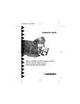
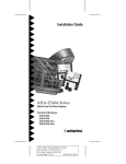
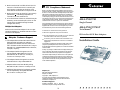
3. Make sure the SCSI hard disk drive SCSI ID is set to ID 0. The drive SCSI ID is normally set with jumpers or switches on the drive. Each SCSI devices should be set to a unique SCSI ID. 4. Make sure the SCSI termination is set correctly. (See Section 5 , Connecting Peripherals for information on SCSI termination.) 5. A low-level format of the SCSI hard disk may be necessary. Be sure to backup first, then run the Format utility accessible through the EISA Configuration utility. Multiple Host Adapters Make sure that each host adapter is set to a separate BIOS address. Or, disable the BIOS on all but one of the host adapters. 9 • • • • • Adaptec Customer Support The Adaptec electronic Bulletin Board Service (BBS) provides information on software upgrades, new releases, technical advice, and more. The BBS can be reached 24 hours a day at 408-945-7727; 1200/2400/9600 baud, 8 data bits, 1 stop bit, no parity. The Adaptec Technical Support Hot Line can be reached at 800-959-SCSI (7274), or 408-945-2550; M-Th: 6:00 a.m. to 5:00 p.m., F: 6:00 a.m. to 3:00 p.m. PST. The Adaptec Technical Support FAX can be reached 24 hours a day at 408-945-6776. 10 FCC Compliance Statement NOTE: This equipment has been tested and found to comply with the limits for a Class B digital device, pursuant to Part 15 of the FCC rules. These limits are designed to provide reasonable protection against harmful interference in residential installations. This equipment generates, uses, and can radiate radio frequency energy, and if not installed and used in accordance with the instructions, may cause harmful interference to radio communications. However, there is no guarantee that interference will not occur in a particular installation. If this equipment does cause interference to radio or television equipment reception, which can be determined by turning the equipment off and on, the user is encouraged to try to correct the interference by one or more of the following measures: • • • • Reorient or relocate the receiving antenna AHA-2740/2742 Single-Channel AHA-2740-T/2742-T TwinChannel Move the equipment away from the receiver Plug the equipment into an outlet on a circuit different from that to which the receiver is powered If necessary, the user should consult the dealer or an experienced radio/television technician for additional suggestions EISA-to-Fast SCSI Host Adapters Installation Guide CAUTION: Only equipment certified to comply with Class B (computer input/output devices, terminals, printers, etc.) should be attached to this equipment, and must have shielded interface cables. Finally, any change or modifications to the equipment by the user not expressly approved by the grantee or manufacturer could void the user’s authority to operate such equipment. This device complies with part 15 of the FCC rules. Operation is subject to the following two conditions: (1) this device may not cause harmful interference and (2) this device must accept any interference received, including interference that may cause undesired operation. Adaptec software can be ordered by calling 800-442-7274; M-F: 5:00 a.m. to 6:00 p.m. PST. Additional documentation for Adaptec products can be requested by calling 800-934-2766; M-F: 5:00 a.m. to 6:00 p.m. PST. Adaptec, Inc. 691 South Milpitas Boulevard Milpitas, CA 95035 Copyright 1993, Adaptec, Inc. All rights reserved. Adaptec and the Adaptec logo are registered trademarks, and AHA and TwinChannel are trademarks of Adaptec, Inc. Printed in Singapore Stock No.: 510364-00 Rev. A RQ 1/93 Information subject to change without notice. 10 11 ▲ ▲ ▲ ▲ ▲ ▲ ▲ ▲ ▲ ▲ ▲ 1 Table 1. Host Adapter Components Getting Started This guide provides the basic steps required for installation of the AHA®-2740/2742 and the AHA-2740-T/2742-T EISA-to-Fast SCSI Host Adapters. Procedures for all adapters are the same except when regarding the on-board floppy controller on the AHA-2742/2742-T. Installation of the host adapter includes: 1. Installing the AHA (Adaptec Host Adapter) board in an EISA system. 2. Installing the SCSI cable(s) and SCSI peripheral devices. Location J1 J2 J3 J4 J5 J6 U1 U2 U5 U9 U10 Description External LED Connector Floppy Connector (AHA-2742/2742-T only) SCSI Channel A Internal Connector Floppy Enable Jumper (AHA-2742/2742-T only) SCSI Channel B Internal Connector (AHA-2740-T/2742-T only) SCSI Channel A External Connector Floppy Controller (AHA-2742/2742-T only) RAM Host Adapter BIOS AIC-7770 Bus Master SCSI Chip AIC-701 Configuration Chip 3. Terminating the SCSI bus. 4. Adjusting the host adapter configuration settings if necessary. Board Layout Figure 1 shows the location of the major components on the host adapter; Table 1 provides a description of each component. J1 U1 U2 J4 J3 U5 PIN 1 PIN 1 PIN 1 J2 Default Settings Your host adapter is already configured for the majority of EISA class computers. Table 2 lists the default settings of your host adapter. Refer to Section 6 , Configuring the Host Adapter for information on changing any of these settings: 5. Loading software if necessary. 2 3 Table 2. Host Adapter Default Settings Description Interrupt Level Bus Release Time Data FIFO Threshold Host Adapter BIOS Address Host Adapter SCSI ID SCSI Bus Parity SCSI Selection Timeout SCSI Bus Reset at Power-on SCSI Bus Termination Greater Than 1 GByte Support More Than Two Drive Support Removable Drive Support Default Setting IRQ 11 60 BCLKS 100% D8000h Device ID 7 Enabled 256 ms Enabled Enabled Disabled Disabled Support removable drive as boot device only The On-board Floppy Controller (AHA-2742/2742-T only) J5 U9 U10 J6 • Figure 1. Host Adapter Board Layout If your floppy diskette drives are already running under another controller, disable the on-board floppy controller by removing the jumper shunt on jumper J4. 1 2 • To use the on-board floppy controller, leave the jumper shunt installed on jumper J4 and then disable your existing floppy controller; refer to your computer or floppy controller user documentation. 4 Installing the Host Adapter Board Installation CAUTION Turn OFF and disconnect power to the system and external equipment. Always refer to your system’s documentation for instructions on removing the system cover and adding option boards. 1. Remove the cover of your EISA personal computer to expose the EISA bus slots on the motherboard. 2. Locate an unused EISA slot in your system which supports bus master operations (refer to the host system documentation for details) and remove the corresponding slot cover. 3. Align and insert the host adapter in the EISA slot. Secure the host adapter in your system. 5 Connecting Peripherals Connecting Cables SCSI devices are cabled together in a single continuous daisy-chain of devices, called the SCSI bus. SCSI Channel A and SCSI Channel B (AHA-2740-T/2742-T only) can each accommodate a SCSI bus with up to seven SCSI devices connected. SCSI Channel A is comprised of both an internal and external connector. Note Only Single-Ended SCSI devices are supported by the AHA-2740/2742/2740-T/2742-T host adapters. Consult your SCSI device user documentation. Internal SCSI Cables When connecting the 50-pin internal SCSI ribbon cables to both the host adapter and internal SCSI peripheral device(s), make sure that Pin 1 3 orientation is maintained throughout the bus. Pin 1 of the SCSI cable is designated by a colored stripe on one edge of the flat ribbon cable. Pin 1 of the host adapter or SCSI device connector is usually designated by a delta or arrow symbol (▲) on the connector. The internal connectors for SCSI Channel A and SCSI Channel B (AHA-2740-T/2742-T only) use a 50-pin SCSI flat ribbon cable with a 50-pin header internal connector. External SCSI Cables The external connector for SCSI Channel A uses a 50-pin shielded cable with a high-density external connector. External cable connectors are keyed and can only be plugged in one way; Pin 1 orientation is automatic. Floppy Cables (AHA-2742/2742-T only) The floppy connector uses a 34-pin floppy ribbon cable with a 34-pin header connector. Make sure to maintain Pin 1 orientation as previously described in Internal SCSI Cables. Enabling or disabling host adapter termination is software selectable only. To disable termination on the host adapter, refer to Section 6 , Configuring the Host Adapter for instructions. Select the Host Adapter Terminating Other SCSI Peripheral Devices Check the manufacturer’s documentation to determine how to enable or disable SCSI bus termination on your SCSI peripheral device(s). SCSI ID Setting For each device located on the SCSI bus, a unique SCSI ID (0-7) must be reserved. The default value for your host adapter is SCSI ID 7. Refer to Section 6 , Configuring the Host Adapter for instructions on changing the SCSI ID for the host adapter. Refer to the SCSI device documentation for information on changing the SCSI ID on other SCSI devices. Terminating the Host Adapter The factory installed bus terminators on the host adapter are enabled by default. Host adapter termination should be disabled if you attach SCSI devices to both internal and external connectors, since the host adapter would then be in the middle of the SCSI bus. Table 3 describes the three possible SCSI device and host adapter (AHA) configurations. Table 3. SCSI Device and AHA Configuration Devices Connected To Host Adapter AHA Termination Internal devices only (AHA at end of cable) On/Enabled External devices only (AHA at end of cable) On/Enabled Internal and External devices (AHA in between) Off/Disabled 4 Once the files have been copied, run the option in the Configuration utility that allows you to configure the EISA slot in which the host adapter is installed. A screen listing the host adapter parameters is displayed. Note If your host adapter is an AHA-2740-T/2742-T, a set of parameters for SCSI Channel B is displayed and can be configured. Configure the Host Adapter Parameters Reassemble the System Select values for each setting as instructed on the screen’s menu. Follow your system and SCSI device documentation to replace the system cover and connect all system and SCSI device power cables. Interrupt Level–selects the IRQ level of the host adapter. Termination on the SCSI Bus The first and last physical SCSI devices on the ends of the SCSI bus must have a set of resistors called terminators either installed or enabled. All other SCSI devices installed between the ends of the SCSI bus must have their terminators either removed or disabled. provide such an option, you can also use the DOS Copy command to copy these files to the bootable Configuration diskette. 6 Configuring the Host Adapter A Configuration diskette containing an EISA Configuration utility is normally supplied by the EISA system vendor. Depending on the EISA Configuration utility supplied with your system, host adapter configuration will vary. The basic steps involved in running the EISA Configuration utility are explained in this section. Run the EISA Configuration Utility Place the bootable Configuration diskette in an operative drive and reset the system to boot from this diskette. Run the EISA Configuration utility as instructed by the EISA system vendor. Copying Files The Configuration utility typically allows you to select among a number of options, including copying new configuration files. Select this option to install the !adp7771.cfg and adp7770.ovl files from the host adapter diskette to the bootable Configuration diskette. If the Configuration utility does not 5 Bus Release Time–selects the EISA bus release time used when the host adapter gets preempted in bus master mode. Data FIFO Threshold–selects the data FIFO threshold percentage used by the host adapter. Host Adapter BIOS Address–selects the base BIOS address of the host adapter. Host Adapter SCSI ID–selects the SCSI ID (0-7) for the host adapter. SCSI IDs 0 and 1 should be reserved for SCSI hard disk drives. Each installed SCSI device must have a unique SCSI ID. SCSI Bus Parity–allows you to enable or disable SCSI bus parity on the host adapter. SCSI Selection Timeout–selects the SCSI selection timeout used by the host adapter during the SCSI selection phase. SCSI Bus Reset at Power-on–allows you to enable or disable a SCSI bus reset generated by the host adapter during its power-on initialization, and after a Hard Reset. 6 SCSI Bus Termination–allows you to enable or disable SCSI termination on the host adapter. BIOS and SCSI Device Configuration–sets BIOS and SCSI device options. Refer to the following section for information on these options. BIOS and SCSI Device Configuration BIOS Configuration This option allows you to configure the host adapter BIOS. Greater Than 1 GByte Drive Support–provides a mechanism for using a hard disk with a capacity greater than 1 GByte. If this option is enabled, the following translation schemes are used: • Hard disks ≤ 1 GByte use a translation scheme of 64 heads, 32 sectors per track • Hard disks ≥ 1 GByte use a translation scheme of 255 heads, 63 sectors per track More Than Two Drives Support–allows BIOS to support more than two SCSI hard disks (supported by DOS 5.0 and above). If this option is enabled, up to eight hard disks can be attached to INT 13h. Removable Drive Support–allows you to select one of the following options for configuring removable drive support: • • • Error if Device Not Found–selects whether the operator will be notified if the BIOS is unable to find the device during the boot procedure. BIOS Support Option–allows devices attached to the SCSI bus to be recognized by the host adapter BIOS and installed as devices on the system without the need for device driver software. Send Start Command–is used for devices that require a command to start up after power-on. Most devices do not require this. Initiate Synch Negotiation–allows the host adapter to attempt to use the faster synchronous protocol for data transfers on the SCSI bus. If deselected, the transfer will be done asynchronously, unless a SCSI device itself requests synchronous negotiation. Enable Disconnection–allows the device to go off-line while performing an operation. This allows the host adapter to perform other operations on the SCSI bus while the SCSI device is temporarily disconnected. Maximum Synch Transfer Rate–allows selection of the highest data transfer speed that the host adapter will attempt with that peripheral. The host adapter supports rates up to the Fast SCSI maximum of 10 MBytes/second. Disable removable drive support When configuration of the SCSI devices is complete, save the configuration and exit the EISA Configuration utility. Support removable drive as boot device only Utilities Support all removable drives Two SCSI utilities are available with your host adapter: Note Support for removable drives means only that the BIOS allows for use of a removable drive as if it were a fixed disk drive; it does not mean that the disk media can be removed during operation. Format Disk–accesses the Adaptec SCSI LowLevel Format utility. Most SCSI disk drives are pre-formatted, and do not need re-formatting. This option allows you to customize the configuration of the SCSI devices connected on the SCSI bus. Select values for each setting as instructed on the screen’s menu. Host Adapter Diagnostics–runs a diagnostic on your host adapter by doing DMA transfers between the SCSI host adapter and system memory. You should run this utility without any device drivers or TSRs loaded. This test will run indefinitely until Esc is pressed. 7 8 SCSI Device Configuration 7 Operating Environment Software DOS/Windows Under MS-DOS® 5.0 or higher, up to eight SCSI hard disk drives can be connected to the host adapter without additional software. (Older versions of DOS support up to two hard disk drives.) Additional software is required if you desire to do the following: • • • Support more than two hard disk drives under versions of DOS prior to MS-DOS 5.0 Use devices other than hard disk drives such as SCSI tape, CD-ROM, scanners, etc. Treat removable media devices as removable while your computer is running Refer to the documentation received with your I/O environment software package for instructions on loading your SCSI I/O operating environment for versions of DOS prior to MS-DOS 5.0. Novell NetWare®, OS/2®, and UNIX® Adaptec is working with major operating system suppliers to provide embedded support in their operating systems. Please contact Adaptec or your operating system vendor for information on the current schedule for I/O operating environment software support. 8 Troubleshooting System Will Not Boot From a SCSI Disk Drive If both SCSI and non-SCSI disk drives are installed, then the non-SCSI disk drive is always the boot device. If there is no non-SCSI disk drive: 1. Make sure your computer system’s CMOS Setup is set to No Drives Installed, as is required for SCSI host adapters. 2. Try enabling the BIOS Support Option in the BIOS and SCSI Device Configuration option. See Section 6 , Configuring the Host Adapter. 9