1
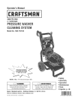
Owner's Manual
ICRRFTSMAN+I
6.75 HORSEPOWER
2500 PSI
2.5 GPM
PRESSURE WASHER
CLEANING SYSTEM
Model No. 580.767451
HOURS:
•
•
•
•
•
•
Mon. - FrL 8 a.m. to 5 p.m. (CT)
CAUTION:
Before using this product,
read this manual and follow all Safety
Rules and Operating Instructions,
SEARS,
ROEBUCK
and CO,,
Hoffman
Estates,
Visit our Craftsman website: www.sears.com/craftsman
Past No.
193946GS
Dral)
0 (10/17/2003)
IL 60179
U.S.A.
Safety
Assembly
Operation
Maintenance
Parts
Espafiol
WARRANTY
....................................
SAFETY RULES
...............................
KNOW YOUR PRESSURE WASHER
ASSEMBLY
OPERATION
2
2-4
................
5
...................................
6-8
.................................
9-11
MAINTENANCE
..............................
SPECIFICATIONS
12-16
...............................
LIMITED
12
WARRANTY
STORAGE
..................................
TROUBLESHOOTING
REPLACEMENT
17-18
............................
19
PARTS .......................
20-25
NOTES .....................................
26-28
EMISSION CONTROL WARRANTY .................
29
ESPAigOL ...................................
30-47
HOW TO ORDER PARTS ................
ON CRAFTSMAN
PRESSURE
BACK PAGE
WASHER
For one year from the date of purchase, when this Craftsman pressure washer is maintained and operated
according to the instructions in the owner's manual, Sears will repair, free of charge, any defect in material and
workmanship.
if this washer is used for commercial purposes, this warranty applies for only 90 days from the date of purchase. If this pressure washer is used for rental purposes, this warranty applies for only 30 days after date of
purchase.
This warranty does not cover:
Expendable items such as spark plugs or air filters, which become worn during normal use.
Repairs necessary because of operator abuse or negligence, including damage resulting from no water
being supplied to pump or failure to maintain the equipment according to the instructions contained in the
owner's manual.
Warranty service is available by returning the pressure washer to the nearest Sears service center or dealer in
the United States.
This warranty gives you specific legal rights and you may also have other rights, which vary from state to state.
Sears, Roebuck
_k
and Co., Dept. 817WA,
Hoffman
Estates,
IL 60179
This
the safety that
alert follow
symbol.
is used to avoid
alert you
to potential
safetyis messages
thisIt symbol
possible
injury personal
or death. injury hazards. Obey all
_Read familiarthis
manual
become
with
your carefully
pressure and
washer.
Know its
applications, its limitations, and any hazards
involved.
The safety alert symbol (_,)
is used with a signal
word (DANGER, CAUTION, WARNING), a pictorial
and/or a safety message to alert you to hazards.
DANGER indicates a hazard which, if not avoided, will
result in death or serious injury. WARNING indicates a
hazard which, if not avoided, could result in death or
serious injury. CAUTION indicates a hazard which, if
not avoided, might result in minor or moderate injury.
CAUTION, when used without the alert symbol,
indicates a situation that could result in equipment
damage. Follow safety messages to avoid or reduce
the risk of injury or death.
Hazard Symbols
and Meanings
Toxic Fumes
Slippery Surface
Fire
Moving Parts
Electrical Shock
Fall
Explosion
Flying Objects
Fluid Injection
Hot Surface
Kickback
In the State of California a spark arrester is required
_y law (Section 4442 of the California Public
Resources Code). Other states may have similar laws.
Federal laws apply on federal lands. If you equip the
"nuffler with a spark arrester, it must be maintained in
_=ffectiveworking order.You can order a spark arrester
_hrough your authorized Sears service dealer.
WARNING
WHEN ADDING FUEL
WARNING
I
The engine exhaust from this product contains
chemicals known to the State of California to cause
cancer, b rth defects, or other reproduct ve harm,
I
DANGER
Turn pressure washer OFF and let it cool at least
2 minutes before removing gas cap.
Fill fuel tank outdoors.
DO NOT overfill tank. Allow space for fuel expansion.
Keep fuel away from sparks, open flames, pilot lights,
heat, and other ignition sources.
DO NOT light a cigarette or smoke.
VHEN OPERATING EQUIPMENT
DO NOT tip engine or equipment at angle which causes
fuel to spill.
DO NOT spray flammable liquids.
VHEN TRANSPORTING OR REPAIRING EQUIPMENT
Transport/repair
valve OFF.
Operate pressure washer ONLY outdoors.
Use a respirator or mask whenever there is a chance
that vapors may be inhaled.
Read all instructions packed with mask so you are certain
mask will provide necessary protection against inhaling
harmful vapors.
with fuel tank EMPTY or with fuel shutoff
VHEN STORING FUEL OR EQUIPMENT
TANK
WITH FUEL IN
Store away from furnaces, stoves, water heaters, clothes
dryers or other appliances that have pilot light or other
ignition source because they can ignite fuel vapors.
WARNING
WARNING
Keep water spray away from electric wiring or fatal
electric shock may result.
WANNING
NEVER aim spray gun at people, animals or plants.
DO NOT allow CHILDREN to operate pressure washer.
NEVER repair high pressure hose. Replace it.
Keep high pressure hose connected to pump and spray
gun while system is pressurized.
Keep spray nozzle between 8 to 24 inches away from
cleaning surface.
Operate this unit on a stable surface.
WARNING
Cleaning area should have adequate slopes and
drainage to reduce possibility of fails due to slippery
surfaces.
Be extremely careful if you must use pressure washer
from a ladder, scaffolding or any other relatively unstable
location.
DO NOT touch hot surfaces.
Firmly grasp spray gun with both hands when using high
pressure spray to avoid injury if gun kicks back.
Allow equipment to cool before touching.
Stay clear of exhaust gases.
WARNING
CAUTION
• DO NOT secure spray gun in Open position.
• Tie up iong hair a_
remove jewelry.
WARNING
• DO NOT leave spray gun unattended while machine is
running.
, NEVER use a spray gun which does not have a trigger
!ock
or trigger guard in Place and in working order.
Always be Certain Spray gun, nozzles and accessories
are correctly attached.
CAUTION
• NEVER aim spray gun at plants.
CAUTION
wire where it cannot contact spark plug.
• If you nave uuestions about ir_ended use• ask dealer or
contact Sears.
WARNING
• NEVER ocerate units with broken or missing parts, or
without oretective housing or covers.
• DO NOT by-pass any safety device on this machine.
• Before starting pressure washer in cold weather, check
all parts of the e_u_ment to be sure ice has not formed
there
in vicinity of equipment in use.
CAUTION
• D0 NOT tamper with g0vemed
• DO NOT operate pressure washer above rated pressure;
• NEVER move machine by pulling on high pressure hose.
Use handle orevided on unit
• Check fuel system for leaks or signs of deterioration.
such as chafed or spongy hose. loose or missing
cJamDs, or oamaged tank or caD. Correct all defects
before operating pressure washer
• This equipment is designed to be used with Sears
authorized parts ONLY. If edu_pment is used with par_s
that DO NOT comply with minimum specifications user
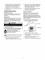
assumes atl risks and liabilities.
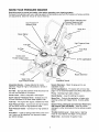
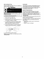
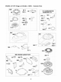
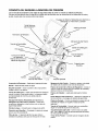
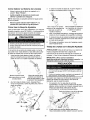
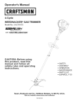
KNOW YOUR PRESSURE
WASHER
Read this owner's manual and safety rules before operating your cleaning system.
Compare the illustrations with your cleaning system to familiarize yourself with the locations of various controls
and adjustments. Save this manual for future reference.
Dial-A-Cleaner
Selector Knob
TM
System Rinse, Detergent and
i ChemiCal Reservoirs with
Internal Filter and Baffle
\\
\
\
}
\
\
Recoil Starter
Spray Gun
\
\
High Pressure Hose
Air Filter
Hose Reel
Choke Lever
Throttle Control Lever
Oil
Nozzle Extension
Pump
High Pressure Outlet
Adjustable Nozzle - Always attached to nozzle
extension. Adjust for high or low pressure; narrow or
fan spray.
Air Filter - Dry type filter element limits the amount of
dirt and dust that gets in the engine.
Fill Cap/Dipstick
Jstable Nozzle
Nozzle Extension - Attach to spray gun to use
adjustable nozzle.
Oil Fill CaplDipstick - Fill engine with oil here. See
page 7 for oil recommendations and filling instructions.
Pump - Develops high water pressure.
Choke Lever - Used to help start a cold engine.
Recoil Starter - Used for starting the engine.
Dial-A-Cleaner TM Selector Knob - Selects any one
of three chemicals or the clean water system rinse.
Spray Gun - Controls the application of water onto
cleaning surface with trigger device. Includes safety
latch.
Fuel Cap - Fill engine with regular unleaded fuel here.
High Pressure Hose - Connect one end to the spray
gun and other end to the high pressure outlet.
High Pressure
hose.
Outlet - Connection for high pressure
Hose Reel -- Used for storing hose while unit is not in
use, Hose must be detached from pump and spray
gun before storage,
System Rinse, Detergent and Chemical Reservoirs
with Internal Filter and Baffle - Used to provide
detergent or other chemicals to the low pressure water
stream.
Throttle Control Lever - Sets engine in starting
mode for recoil starter and stops running engine.
Water Inlet - Connection for garden hose.
Yourcleaningsystemrequiressomeassembly
and is
ready for use only after it has been properly serviced
with the recommended oil and fuel.
If you have any problems with the assembly of
your pressure washer, please call the pressure
washer helpline at 1-800-222-3136.
IMPORTANT: Any attempt to run the engine before it
has been serviced with the recommended oil will result
in an engine failure.
REMOVE PRESSURE
FROM CARTON
WASHER
Become familiar with each piece before assembling
the pressure washer. Identify all contents with the
illustration on page 5. If any parts are missing or
damaged, call the pressure washer helpline at
1-800-222-3136.
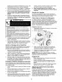
ASSEMBLING
CLEANING
SYSTEM
Your Craftsman cleaning system will need assembly
before operation:
1. Attach hose reel.
2.
Add oil to engine crankcase.
3.
Add fuel to fuel tank.
Open carton and slice two corners opposite guide
handle from top to bottom so the panel can be
folded down flat.
4.
Connect high pressure hose to spray gun and pump.
5.
Connect water supply to pump.
2.
Remove hose reel box, fillers, and parts bag
shipped with cleaning system.
Assembling
3.
Remove spray gun, nozzle extension, and engine
oil from fillers.
4.
Roll cleaning system out open end of carton.
5.
Raise guide handle, secure in place.
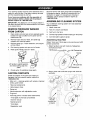
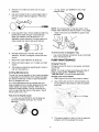
1.
Hose
Reel
Obtain 14ram and 10ram open end wrenches and a #2
phillips screwdriver.
1. Attach handle to reel with Iocknuts, flatwashers,
and bolts as shown.
M6 Screws
Handle
Lift handle to Upright position
ands!ide locking capsinto
place
6.
M6 Locknuts
Flatwashers
Check carton for additional loose parts.
CARTON
CONTENTS
2. Secure hose reel to left side upright with Iocknuts
and bolts.
Check all contents. If any parts are missing or
damaged, call the pressure washer helpline at
1-800-222-3136.
Main unit -- cleaning system with wheels, chemical
tanks, guide handle
Hose reel components
High pressure hose
Spray gun
Nozzle extension with adjustable nozzle
Engine oil
Parts bag (which includes items listed below)
Three-pack of chemical concentrates
Owner's manual
Maintenance kit
Tank labels
Registration card
mounts
,through slot
. on panel
/
NOTE: There may be small tube adapters included
with the hose reel kit that are not used on this model.
IMPORTANT: You must take the hose off the reel
when operating your cleaning system. The reel is for
storage purposes only.
Add Engine
Add Fuel
_k
ARNINGt
fill fuel
tank is
indoors.
NEVER
fill fuelNEVER
tank when
engine
running or
hot. Allow unit to cool for two minutes before
refueling. DO NOT light a cigarette or smoke
when filling the fuel tank.
_k
NEVER
tank completely
full.ARNING1
Provide space
for fill
fuelfuel
expansion.
Wipe
away any fuel spillage from engine and
equipment before starting.
1.
Use fresh, clean unleaded automotive fuel and
store in approved, clean, covered containers. Use
clean fill funnels. NEVER use "stale" fuel left over
Oil
IMPORTANT: Any attempt to crank or start the engine
before it has been properly serviced with the
recommended oil may result in an engine failure.
NOTE: When adding oil to the engine crankcase, use
only high quality detergent oil rated with API service
classification SF, SG, SH, SJ or higher rated SAE 30
weight. DO NOT use special additives.
1. Choose a viscosity according to table below.
--E
from last season or fuel stored for long periods.
STARTING TEMPERATURE
RANGE ANTICIPATED
2.
Clean area around fuel fill cap, remove cap.
3.
Slowly add "UNLEADED" regular fuel to fuel tank.
Use a funnel to prevent spillage. Fill tank to about
1.5" below the bottom of the filler neck.
BEFORE NEXT OIL CHANGE
* The use of multi-viscosity oils (5W-30, 10W-30, etc.)
in temperatures above 40°F (4°C) will result in higher
than normal oil consumption. When using a multiviscosity oil, check oil more frequently.
If using SAE 30 oil in temperatures below 40°F
(4°C), it will result in hard starting and possible
engine bore damage due to inadequate lubrication.
2. Place pressure washer on a level surface.
3.
Clean area around oil fill.
4.
Remove oil fill cap and dipstick.
5.
Wipe dipstick clean, insert it into oil fill hole and
tighten securely, remove dipstick. Add
recommended oil up to "Full" mark on dipstick.
#NN_N_NNNN_N_f
4.
Install fuel cap and wipe up any spilled fuel.
IMPORTANT: It is important to prevent gum deposits
from forming in essential fuel system parts, such as
the carburetor, fuel filter, fuel hose or tank during
storage. Also, experience indicates that
alcehol-blended fuels (called gasohol, ethanol or
methanol) can attract moisture, which leads to
separation and formation of acids during storage.
Acidic gas can damage the fuel system of an engine
while in storage.
To avoid engine problems, the fuel system should be
emptied before storage of 30 days or longer. See
"Storage" on pages 17-18. NEVER use engine or
carburetor cleaner products in the fuel tank or
permanent damage may occur.
©
6.
Pour slowly. Wipe dipstick clean each time oil
level is checked. DO NOT overfill.
NOTE: You may not need to use all the supplied oil.
7. Install oil fill plug and dipstick, tighten securely.
NOTE: Check oil often during engine break-in.
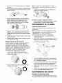
Connect
Hose and Water Supply
to Pump
IMPORTANT: To avoid pump damage, you must
assemble the nozzle extension to the spray gun and
attach all hoses before you start the engine.
1. Uncoil high pressure hose and attach one end of
hose to base of spray gun. Tighten by hand.
2. Removeanddiscardshippingcapsfrompumpinlet
andoutlet.
3. Attachother end of high pressure hose to high
7.
Turn ON water and squeeze trigger on spray gun
to purge pump system of air and impurities.
WARNING
pressure outlet on pump. Tighten by hand.
nspe t
screen DO NOT
use if damaged;
clean if dirty.
wearing adequate eye protection.
CHECKLIST
ENGINE
BEFORE STARTING
Review the unit to ensure you have performed all of
the following:
1. Check that hose reel fasteners are tight.
Before connecting garden hose to water inlet,
inspect inlet screen. Clean screen if it contains
debris or have it replaced if damaged. Refer to
section =O-Ring Maintenance" if inlet screen is
damaged. DO NOT run pressure washer if inlet
screen is damaged.
2.
Check that oil has been added to proper level in
engine crankcase.
3.
Add proper fuel to fuel tank.
4.
Check for proper hose connections (high pressure
and water supply) and that there are no kinks,
cuts, or damage to the high pressure hose.
Run water through garden hose for 30 seconds to
flush it of debris. Turn off water.
5.
Provide proper water supply (not to exceed
100°F).
IMPORTANT: DO NOT siphon standing water for the
water supply. Use ONLY cold water (less than 100°F).
6. Connect garden hose (not to exceed 50 feet in
length) to water inlet. Tighten by hand.
6.
Be sure to read "Safety Rules" and =Operation"
sections before using the cleaning system.
4.
5.
CAUTION
this instruction will void warranty.
HOW TO USE YOUR CLEANING
SYSTEM
9,
Move the choke lever to the =Choke" position,
If you have any problems operating your pressure
washer, please call the pressure washer helpline at
1-800-222-3136.
To Start
Your
Cleaning
System
To start your engine-powered cleaning system for the
first time, follow these instructions step-by-step. This
information also applies whenever you start the engine
after you have let the pressure washer sit idle for at
least a day.
1. Place pressure washer near an outside water
source capable of supplying water at a flow rate
greater than 3.5 gallons per minute and no less
than 20 PSI at pressure washer end of garden
hose.
2.
Check that high pressure hose is tightly connected
to spray gun and pump. See "Assembling Your
Pressure Washer" for illustrations.
3.
Make sure unit is in a level position.
4.
Connect garden hose to water inlet on pressure
washer pump. Turn ON water.
NOTE: For a warm engine, be sure the choke lever is
in the "Run" position.
10. Move the throttle lever to "Fast" position, shown
on unit as a rabbit.
11. Place your left foot on the lower frame and grasp
the handle as shown. Your unit may appear
slightly different from that shown here.
CAUTION
this instruction,
5.
Squeeze trigger on gun to purge pump system of
air and impurities.
6.
Attach nozzle extension to spray gun. Tighten by
hand.
\\
12. Pull the starter grip handle lightly with your right
hand until you feel some resistance, then pull
briskly.
13. Return the starter grip handle slowly. DO NOT let
rope "snap back" against starter.
14. When engine starts, slowly move choke lever to
the "Run" position. If engine falters, move choke
lever to the =Choke" position, then to the "Run"
position.
\
7.
Position nozzle in low pressure mode (slide nozzle
forward) and squeeze trigger on spray gun to
relieve pressure caused by turning ON water.
Water will flow out of gun in a thin stream.
Continue to hold trigger until there is a steady
stream of water and no air remains in system.
Release trigger.
8.
Engage the safety latch to the spray gun trigger.
safetyLatch
15. If engine fails to start after six pulls, move choke
lever to the "Run" position. If engine fires, but
does not continue to run, move choke lever to the
"Choke" position, then to the "Run" position.
pu]!ed and engine fai!s to start,
NOTE: Always keep the throttle lever in the "Fast"
position when operating the pressure washer,
How
to Stop Your Cleaning
System
.
Move throttle lever to =Stop" position.
Squeeze trigger on the spray gun to relieve
pressure in the hose.
Twisting nozzle adjusts spray pattern from a
narrow pattern to a fan pattern.
\
NOTE: A small amount of water will squirt out when
you release the pressure.
• Rotate the Dial-A-Cleaner TM selector knob to the
OFF position to prevent chemical leakage.
How
To Use
the Adjustable
Nozzle
Now that you know how to START and STOP your
pressure washer, the information in this section will tell
you how to adjust the spray pattern and apply
detergent or other cleaning chemicals.
Twist nozzle counterclockwise for fan pattern;
CAUTION
4.
.
• NEVER adiLtStsprayPattem when spraying.
NEVER
put hands in front of nozzle to adjust Spray pattern,
6.
Your unit is equipped with an adjustable nozzle that
permits you to adjust the spray pressure and the spray
pattern, as follows:
1. Push nozzle forward (backward) to adjust spray
pattern for high (low) spray pressure.
Twist nozzle clockwise for
narrow
spray pattern:
For most effective cleaning, keep spray nozzle
from 8 to 24 inches away from cleaning surface.
If you get spray nozzle too close, especially using
high pressure mode, you may damage surface
being cleaned.
DO NOT get closer than 6 inches when cleaning
tires.
Cleaning
With
The Adjustable
Nozzle
CAUTION] Before starting your cleaning system,
make sure you have read and followed the instructions
in the sections "Assembling your Cleaning System"
and "To Start your Cleaning System".
IMPORTANT: Use chemicals designed specifically
for pressure washers. Household detergents could
damage the pump.
CAUTION
slide nozzle backward for
high pressure mode
2.
,Starting the engine without all the hoses connected and
without the water turned ON will damage the pump:
Sl!de nozzle forward for
low pressure mode and
detergent application
Up to three (3) different solutions can be carried with
the cleaning system at one time. To apply detergent
follow these steps:
1. Dilution is necessary when using supplied chemical
packets. Simply snip one corner of plastic pouch,
pour chemical into tank, then fill tank with clean
water. Label tanks with provided tank labels.
Point nozzle toward ground, disengage safety
latch, and press trigger to test pattern.
10
2. If usinganotherchemicaldesignedforusewith
pressurewashers,preparechemicalsolutionas
requiredbychemicalmanufacturer.
Fillchemical
reservoir(s)
withpreparedsolutionas needed.
3. Rotatethe Dial-A-Cleaner
TM selector knob to letter
4.
Rotate the Dial-A-Cleaner TM selector knob to letter
corresponding to System Rinse tank. As clean
rinse water is drawn through the system, continue
the flow until no detergent foam is observed.
5.
Rotate the Dial-A-Cleaner TM selector knob to
the OFF position when finished to prevent
chemical leakage.
corresponding to desired reservoir.
4.
5.
Push adjustable nozzle forward to low pressure
mode. Chemical cannot be applied with nozzle
in high pressure position.
Siphoning
DO NOT siphon standing water for your water supply.
Contaminated, brackish or dir_ water can damage the
pump. Connect only to household water supply.
Connect garden hose to water inlet, check that
high pressure hose is connected to spray gun and
pump (see pages 7-8), and start engine.
How to Use the Hose Reel
WARNING
Your pressure washer is equipped with a hose reel
that is designed to store your hose when unit is not in
use. These instructions are for short term storage only.
For long term storage see "Storage" on page 16.
After each use:
• Kee# seray nozzle between 8 to 24 inches away from
cleaning surface.
• Operate this unit on a stable surface.
1.
2.
• Be extremely careful if you must use the pressure
washer from a ladder, scaffolding or any other relatively
unstable location.
Disconnect hose from spray gun and high
pressure outlet on pump.
Drain water from hose.
3.
Slide one end of hose into hole on hose reel. Turn
hose reel with handle to coil hose onto reel.
4.
Push other end of hose into clip on side of unit.
• Firmly grasp spray gun with beth hands when using high
pressure spray to avoid injury if gun kicks back.
6.
Start at lower portion
work upward,
strokes.
7.
of area to be washed
and
using long, even overlapping
Allow detergent to 'soak in' (between 3-5 minutes)
before washing and rinsing. Reapply as needed to
prevent surface from drying.
Wash and Rinse Surface
After you have applied detergent, scour the surface
with the high pressure water stream and then rinse it
clean, as follows:
1.
IMPORTANT: DO NOT use your pressure washer with
the hose coiled onto the hose reel. The hose reel is for
storage purposes only.
Pull adjustable nozzle backward for high pressure
mode. Chemical will not flow when in high
pressure mode.
Tips
NEVER use garden hose inlet to siphon detergent
Test a small area of the surface to be cleaned.
Make sure there is no surface damage caused by
the high pressure spray.
2.
.
or wax,
If you hold the spray nozzle too far away from the
object being cleaned, washing will not be as
effective.
Expand spray pattern for a more gentle rinsing
action. Start at top of area to be rinsed, working
down with same action as for cleaning.
Rinse
System
-
After Every Use
Automatic Cool Down System
(Thermal
Relief)
It is imperative that the chemical dispensing system be
rinsed after each use to prevent clogging or leaks:
1. Fill System Rinse reservoir with clean water.
2.
Before disconnecting water supply, start your
cleaning system.
3.
Push nozzle forward for low pressure mode.
Always store the cleaning system with the Dial-ACleaner TM selector knob in the OFF position.
If you run the engine on your pressure washer for
3-5 minutes without pressing the trigger on the spray
gun, circulating water in the pump can reach
temperatures above 125°F. The system engages to
cool the pump by discharging the warm water onto
the ground,
11
OWNER'S
RESPONSIBILITIES
Follow the hourly or calendar intervals, whichever occurs first.
More frequent service is required when operating in adverse conditions noted below.
MA,NTEt._NCE
SCHEouLE
FILl_ IN DATES AS YOU COMPLETE
REGULAR SERVICE
....
HA.....j..
UU"LY
BefOre E_h
MAINTENANCE
PRESSURE
WASHER
Check/clean
water inlet
screen
Every 25
HPurs or
Yeady
Use
TASK
_.--'.
U_"_'_AH
'_N...
_ '"
I..T'_....
_'KVAL_
Every 50
HpUr_ or
Yeady
SERVICE DATES
Every 100
HOUrs Or
Yearly
xt
on pump.
I x
Check high pressure hose.
Check detergent
hose
Check spray gun and assembly for leaks.
Purge pump of air and contaminants.
x
Change pump oil
ENGINE
Check oil level.
I
service
aircleaner.
I
X
I X"*
Change engine oil.
X
Replace spark plug
x
Service spark arrester
Prepare for storage
I Prepare unit for storage if it is to remain idle for longer than 30 days.
Clean if clogged. Replace if perforated
Change oil after the first (5) oper_in£
or tom.
hours and every 50 hours thereafter
Change every 25 hours when operating under dirty or
dusty conditions
**
Replace more often under dirty or dusty conditions
PRODUCT
Pressure
SPECIFICATIONS
Washer
GENERAL
The pressure washer's warranty does not cover items
that have been subjected to operator abuse or
negligence, To receive full value from the warranty,
the operator must maintain pressure washer as
instructed in this manual including proper storage as
detailed in "Storage" on pages 17-18,
Specifications
Pressure
Flow Rate
Chemical Mix .........
2500 PSI
25 GPM
Use as directed
Water Supply Temperature
Shipping Weight ........
Not to Exceed 100°F
102 Ibs
Some adjustments will need to be made periodically to
properly maintain your pressure washer,
Engine Specifications
Rated Horsepower ........
Spark Plug Type:
Resistor ................
Long Life Platinum
All service and adjustments should be made at least
once each season, Follow the requirements in the
"Maintenance Schedule" chart above,
675 HP
Champion RC12YC
.......
Set Gap To ...............
Fuel Capacity ................
Oil
Above 40°F ..........
0°F -40°F ............
RECOMMENDATIONS
NOTE: Once a year you should clean or replace the
spark plug and replace the air filter. A new spark plug
and clean air filter assure proper fuel-air mixture and
help your engine run better and last longer.
Champion RC12PYP
0.020 inches (0.50 ram)
1.6 Quarts
If equipped with inflatable tires, keep the air pressure
at the value marked on the tire or within 15 and 40 psi.
SAE 30
SAE 5W-30 or 10W-30
12
BEFORE
EACH USE
Check engine oil level,
Check water inlet screen for damage.
Check high pressure hose for leaks.
Check chemical tanks and filters for damage.
Check spray gun and nozzle extension assembly
for leaks.
Purge pump of air and contaminants.
1.
Detach spray gun and nozzle extension from high
pressure hose. Detach nozzle extension from
spray gun and remove o-ring and screen from
nozzle extension. Flush screen, spray gun, and
nozzle extension with clean water to clear debris.
2.
If screen is damaged, the o-ring kit contains a
replacement in-line filter screen and o-ring. If
undamaged, reuse screen.
3.
Place in-line filter screen into threaded end of nozzle
extension. Direction does not matter. Push screen in
with eraser end of pencil until it rests flat at bottom
of opening. Take care to not bend screen.
PRESSURE WASHER MAINTENANCE
Check
and
Clean
Inlet
Screen
4.
Examine garden hose inlet screen, Clean if it is
clogged or replace if it is torn.
Check
High Pressure
5. Assemble nozzle extension to spray gun, as
described earlier in manual.
Hose
High pressure hoses can develop leaks from wear,
kinking, or abuse. Inspect hose before each use.
Check for cuts, leaks, abrasions, bulging of cover, or
damage or movement of couplings. If any of these
conditions exist, replace hose immediately.
Purge Pump of Air and Contaminants
To remove air from the pump, follow these steps:
1. Set up cleaning system as described in the
"Assembling Your Cleaning System" and connect
water supply.
WARNING
2.
Pull trigger on spray gun and hold until a steady
stream of water appears.
To remove contaminants from the pump, follow these
steps:
1. Set up cleaning system as described in
"Assembling Your Cleaning System", and connect
water supply.
pressure rating of unit.
Check Chemical
Place o-ring into recess. Push o-ring snugly against
in-line filter screen.
Reservoirs
2.
Remove nozzle extension from spray gun.
Tank covers should snap cleanly onto tank. Ensure
chemical labels correctly identify tank contents.
Ensure that the System Rinse tank is filled with clean
water. Ensure that Dial-A-Cleaner TM selector knob
rotates freely between each position. Examine the
tanks and replace if the filter is clogged.
Check Gun and Nozzle extension
3.
Start engine according to instructions in =How To
Use Your Cleaning System".
4.
Pull trigger on spray gun and hold.
5.
When water supply is steady and constant,
engage safety latch and refasten nozzle
extension.
Examine hose connection to spray gun and make sure
it is secure. Test trigger by pressing it and making
sure it springs back into place when you release it. Put
safety latch in UP position and test trigger. You should
not be able to press trigger. Replace spray gun
immediately if it fails any of these tests.
Nozzle
Check In-Line
Maintenance
A pulsing sensation felt while squeezing the spray gun
trigger may be caused by excessive pump pressure.
The principal cause of excessive pump pressure is a
nozzle clogged or restricted with foreign materials,
such as dirt, etc. To correct the problem, immediately
clean the orifice following these instructions:
1. Shut off engine and turn off water supply.
Filter
Refer to the illustration and service the in-line filter if it
becomes clogged, as follows:
2.
Imiine Filter
Nozzle
Extension
o-ring
13
Detach nozzle extension from spray gun. Twist
nozzle clockwise to stream position. Using
supplied 2ram (5/64) allen wrench, remove orifice
from end of nozzle extension.
3. Removein-linefilterfromotherendof nozzle
extension.
4. Usewireincludedinkit(or a smallpaperclip)to
freeanyforeignmaterialcloggingor restricting
orifice.
1 o-ring, yellow, (pin B2264) for end of high
pressure hose.
NOTE: The previous two o-rings are close in size.
Please match carefully to assure proper o-ring usage.
.
1 water inlet screen (pin B2384.) for garden hose
connector.
Using a garden hose, remove additional debris by
back flushing water through nozzle extension.
Back flush between 30 to 60 seconds. Turn
adjustable nozzle extension to stream spray and
move nozzle from low to high while flushing.
iiiiii i!iiiiiiiii
Reinstall orifice and in-line filter into nozzle
extension. DO NOT overtighten orifice with allen
wrench,
To remove a worn or damaged o-ring:
7.
Reconnect nozzle extension to spray gun.
PUMP MAINTENANCE
8.
Reconnect water supply, turn on water, and start
engine.
Changing Pump Oil
9.
Test pressure washer by operating with nozzle in
high and low positions.
6.
O-Ring
Use a small fiathead screwdriver to get underneath
the o-ring and pry it off.
Change oil every 50 hours or once yearly, whichever
occurs first.
NOTE: You must purchase a premeasured bottle of
pump oil, item number 190585GS, by calling
1-800-366-PART or online at www.sears.cem.
Maintenance
Through the normal operation of your cleaning system,
o-rings keep the connections of the hoses and spray
gun tight and leak-free. These o-rings may become
worn or damaged with use.
Change pump oil as follows:
1. Drain engine oil and fuel from pressure washer.
2.
An O-Ring Maintenance Kit is provided with your
cleaning system which includes replacement o-rings,
rubber washer and water inlet filter. Refer to the
instruction sheet provided in the kit to service your
unit's o-rings. Note that not all of the parts in the kit
will be used on your unit.
Parts in the O-Ring Kit Include:
Use a 8mm allen wrench to remove black pump
oil cap between high pressure outlet and garden
hose inlet.
Oil Cap
1 o-ring, red, (pin B2726) for end of spray gun
connection between spray gun and nozzle
extension.
3.
14
Tilt pressure washer to drain oil into an approved
container until it drips slowly from pump.
4.
Tilt pressure washer in opposite direction and
empty premeasured pump oil bottle into same
opening (a small funnel may be helpful).
5.
Install black pump oil cap and tighten firmly.
6.
Set pressure washer in upright position. Add fuel
and engine oil,
.
ENGINE MAINTENANCE
Checking
Oil
4.
When engine crankcase is filled to proper level,
install and tighten oil cap/dipstick.
5.
Wipe up any remaining oil.
Service
Level
Air Cleaner
Your engine will not run properly and may be
damaged if you run it with a dirty air cleaner.
Oil level should be checked prior to each use or at
least every 5 hours of operation, Keep oil level
maintained,
Changing
Slowly pour oil into oil fill opening. Replace and
tighten dipstick, remove and check oil level. Oil
level should be at "Full" mark on dipstick. DO
NOT overfill above that mark.
Service the air cleaner once every 25 hours of
operation or once each year, whichever comes first.
Service more often if operating under dirty or dusty
conditions. Replacements are available at your local
Sears service center.
Oil
Change engine oil after the first 5 hours and every
50 hours or annually thereafter. If you are using your
pressure washer under extremely dirty or dusty
conditions, or in extremely hot weather, change oil
every 25 hours.
To service the air cleaner, follow these steps:
1, Loosen two screws and lift off cover,
CAUTION
Two Screws
certain laboratory animals,
• Thoroughly wash exposed areas With soaP and water.
Cartridge
DON'T POLLUTE. CONSERVE
RESOURCES RETURN USED O L TO
) COLLECTION
KEEP OUT OF CENTERS.
REACH OF CHILDREN.
Change oil while engine is still warm from running, as
follows:
1.
Remove drain plug from the bottom of engine.
2.
Drain oil into a suitable container. When
crankcase is empty, replace drain plug in engine.
15
2.
Carefully remove air cleaner from base.
3.
To clean cartridge, gently tap pleated paper side
on a flat surface.
4.
Install clean (or new) air cleaner in base. Air
cleaner must fit securely in base.
5.
Place cover over air cleaner and tighten screws.
Service
Spark
Carburetor
Plug
Service the spark plug every 100 hours of operation or
yearly, whichever occurs first.
If you think your carburetor needs adjusting, see your
nearest Sears service center. Engine performance
may be affected at altitudes above 3000 to 5000 feet.
For operation at higher elevations, contact your
nearest Sears service center.
WARNING
Spark Arrester
Your engine is not factory-equipped with a spark
attester. In some areas, it is illegal to operate an
engine without a spark attester. Check local laws and
regulations. A spark attester is available from your
nearest Sears service center. For the part number cell
1-800-366-PART.
wire where itcannot contact spar_ plug_
1.
Clean area around spark plug.
2.
Remove and inspect spark plug.
3.
Replace spark plug if the electrodes are worn, or if
the insulator is cracked or chipped.
The spark attester must be serviced every 50 hours to
keep it functioning as designed.
If the engine has been running, the muffler will be very
hot. Allow the muffler to cool before servicing the
spark attester.
Remove spark attester screen for cleaning and
inspection.
For replacement use either the standard resistor
spark plug, Champion RC12YC or the long life
platinum spark plug, Champion RC12PYP.
4.
.
Replace if screen is damaged.
Check electrode gap with wire feeler gauge and
set gap at 0.020 inches (0.50ram), if necessary.
\
6.
Service
Install spark plug, tighten securely.
NOTE: You can purchase a new spark plug by calling
1-800-366-PART.
16
AFTER EACH USE
WINTER
Water should not remain in the unit for long periods of
time. Sediments or minerals can deposit on pump
parts and "freeze" pump action. Follow these
procedures after every use:
1. Flush chemical system by selecting system rinse
tank and run pressure washer with nozzle in low
pressure mode. Flush for one minute or until
chemical is cleared from system.
2.
CAUTION
• Freeze damage is not covered under warranty.
To protect the unit from freezing temperatures:
1. Empty all chemical reservoirs as follows:
Shut off engine and let it cool, then remove all
hoses.
3.
Disconnect spark plug wire from spark plug.
4.
Empty pump of all pumped liquids by pulling recoil
handle about 6 times. This should remove most
liquid in pump.
5.
Rotate the Dial-A-Cleaner
TM
selector knob to the
a.
Disconnect hose connected to chemical inject
fitting on pump. Place end of hose into
suitable container.
b.
Move selector knob to Tank A and open that
tank's cover. Gravity should shortly empty tank
contents into container.
c.
When tank is empty, repeat step (b) for tanks
B and C, using different container for each
chemical.
d
Reconnect hose to chemical inject fitting on
pump. Add 0.5 liter of clean fresh water to
each tank and close tank's covers.
OFF position.
6.
7.
8.
Coil high pressure hose and inspect it for damage.
Cuts in hose or fraying could result in leaks and
loss of pressure. Should any damage be found,
replace hose. DO NOT attempt to repair a
damaged hose. Replace hose with genuine
Craftsman part.
Flush chemical system by selecting a tank and run
pressure washer with nozzle in low pressure
mode. Flush until each tank is empty, then switch
selector knob to next tank. The last tank to be
emptied must be the System Rinse tank.
2.
Disconnect hose from spray gun and high
pressure outlet on pump. Drain water from hose,
gun, and nozzle extension and wipe off hose with
a rag.
.
Slide one end of hose into hole on hose reel. Turn
hose reel with handle to coil hose onto reel. Push
4.
other end of hose into clip on side of unit.
9.
Reconnect spark plug wire to spark plug.
10. Store system in a clean, dry area.
Use PumpSaver, available at Sears retail item
number 7174403, to treat pump. This prevents
freeze damage and lubricates pistons and seals.
If PumpSaver is not available, connect a 3-foot
section of garden hose to water inlet adapter. Pour
RV-antifreeze (antifreeze without alcohol) into
hose. Pull recoil handle twice. Disconnect 3-foot
hose,
_
STORAGE
WARNING1
engine poorly
with fuel
in
the gas tankNEVER
indoors store
or inthe
enclosed,
ventilated areas where fumes may reach an
open flame, a spark, or pilot light.
17
LONG TERM STORAGE
Protect
If you do not plan to use the pressure washer for more
than 30 days, you must prepare the engine for long
term storage.
To protect the pump use Sears pump saver to prevent
freeze damage and lubricate pistons and seals,
NOTE: Sears pump saver, item number 7174403, is
available as an optional accessory, It is not included
with the pressure washer,
It is important to prevent gum deposits from forming in
essential fuel system parts such as the carburetor, fuel
filter, fuel hose or tank during storage, Also,
experience indicates that alcohol-blended fuels (celled
gasohol, ethanol or methanol) can attract moisture,
which leads to separation and formation of acids
during storage. Acidic gas can damage the fuel
system of an engine while in storage,
Protect
Pump
CAUTION
• Freezedamage is not covered under warranty.
To use the pump saver:
Fuel System
CAUTION
Fuel Additive:
If adding a fuel additive, fill the fuel tank with fresh
fuel, If only partially filled, air in the tank will promote
fuel deterioration during storage. Engine and fuel can
be stored up to 24 months with additive.
• Always wear eye protection when using PumpSaver.
Add fuel additive following manufacturer's
instructions,
1. Attach hose on pump saver can to pump inlet.
Connect water supply to pump inlet and turn it ON,
Run the engine outdoors for 10 minutes to be sure
that treated fuel has replaced the untreated fuel in
the carburetor,
If fuel additive is not used, remove all fuel from tank
and run engine until it stops from lack of fuel.
2.
Push in can top to dispense pump saver.
3.
When pump saver fluid begins to exit pump outlet,
the pump is protected.
4.
Remove pump saver from pump inlet.
OTHER
DO NOT store fuel from one season to another,
Change
Oil
If possible, store your unit indoors and cover it to
give protection from dust and dirt. BE SURE TO
EMPTY THE FUEL TANK.
While engine is still warm, drain oil from crankcase,
Refill with recommended grade (see Changing Oil on
page 15).
Oil
Cylinder
IMPORTANT: NEVER cover your cleaning system
while engine and exhaust area are warm,
Bore
Remove spark plug, Squirt about 1 ounce (30 ml)
of engine oil into the cylinder. Cover spark plug
hole with rag. Pull recoil handle slowly to distribute
oil, Avoid spray from spark plug hole.
Install spark plug. DO NOT connect spark plug wire,
18
Pump has following
problems: failure to produce
pressure, erratic pressure,
chattering, loss of pressure,
low water volume.
Detergent fails to mix with
spray.
1
Pull nozzle backward for high
pressure mode.
Water inlet is blocked.
2.
Clear inlet.
3.
Inadequate water supply
3.
Provide adeauate water flow
4.
Inlet hose is kinked or leaking
4.
Straighten =nlet hose, patch leak.
5.
Clogged inlet hose stra=ner
5.
Check and clean inlet hose strainer.
6.
Water supply is over 100"F
6.
Provide cooler water supply.
7
High pressure hose is blocked
or leaks.
7.
Clear blocks in outlet hose.
8.
Gun leaks.
8.
Replaca gun
9.
Nozzle is obstructed
9.
Clean nozzle
t,
Nozzle
2.
in low pressure
mooe
t0. Pump is faulty
10. Contact Sears service facility.
t.
Detergent line ]s collapsed or
kinkeo
I.
2.
Chemical tank filter is clogged
2.
Replace tank.
3.
In-line filter is dirty.
3.
See"Checkln-Line
4.
Nozzle is in high pressure
mode.
4.
Push nozzle forward for low
pressure mode.
5.
Dial-a-Cleaner
5.
Rotate knob for desired chemical.
TM
knob is in off
Recair or replace detergent line
FilteF'
position.
Engine runs good at no-load
but "bogs" when load is
added,
Engine will not start; or
starts and runs rough.
Engine speed is too slow
Move throttle control to FAST position. If
engine still "bogs down", contact Sears
service facility.
1.
Dirty air cleaner.
1.
Clean or replace air cleaner.
2.
Out of gasoline.
2.
Fill fuel tank.
3.
Stale gasoline.
3.
Drain gas tank; fill with fresh fuel.
4.
Spark plug wire not connected
to spark plug.
4.
Connect wire to spark plug.
5.
6.
Bad spark plug.
Water in gasoline.
5.
6.
Replace spark plug.
Drain gas tank; fill with fresh fuel.
7.
Overchoking.
7.
Open choke fully and crank engine.
8.
Excessively rich fuel mixture.
8.
Contact Sears service facility.
9.
Intake valve stuck open or
closed.
9.
Contact Sears service facility.
t0. Engine has lost compression.
10. Contact Sears service facility.
Engine
shuts down during
•
i
operation.
Out of gasoline.
Fill fuel tank.
Engine lacks power.
Dirty air filter.
Replace air filter.
Engine "hunts" or falters.
Choke is opened too soon.
Move choke to halfway position until
engine runs smoothly.
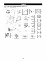
19
CRAFTSMAN
2500 PSI Cleaning
Main Unit -- Exploded View
System
580,767451
8
\
s4
2O
CRAFTSMAN
2500 PSI Cleaning
Main Unit -- Parts List
Item
1
2
3
4
5
6
7
B
9
10
11
12
13
14
15
16
17
18
19
20
21
22
23
24
25
26
27
28
29
30
900
Part #
MB5691GS
M191774GS
B4992GS
194061GS
192133GS
192140GS
192131GS
192t26GS
192127GS
30809GS
194062GS
194066GS
B3454GS
192149GS
194063GS
194064GS
194065GS
194074GS
194075GS
192553GS
21783GS
194076GS
186317GS
190937AGS
B3263GS
190246GS
94804GS
23139DGS
194059GS
192526GS
NSP
System
580.767451
Description
BASE
HANDLE
HOSEREEL
KIT, Chemical Tank
KIT, Engine Mounting Hardware
KIT, Handle Connector
KIT, Pump Mounting Hardware
KiT, Viny$Cap, Base
KIT, Vinyl Cap, Handle
GROMMET
KIT, Pushnut
KIT, Clip Holder
KIT, Tags
KIT, Concentrate, 3 Bottle
KIT, Knob, 4-Way Valve
KIT, Subassy, Valve 4,-way
KIT, Handle Hardware
KiT, Hose, Subassy,
KIT, Hose, Subassy, (cut to length)
KIT, Vibration Mount
VALVE, Thermal Relief
KIT, Caps, Chemical Containers
KIT, Hose Reel Mounting Hardware
ASSY, Wand Adjustable Nozzle
GUN
HOSE
ORIFICE
KEY
ASSY, Pump (see pages 22-23)
KIT, Wheel
ENGINE
Items Not Illustrated
Part #
Description
AB3061BGS BOTTLE, Oil
191922GS
KIT, O-Ring Maintenance
193946GS
MANUAL, Owners
194011GS
K{T, Decal Service
Optional Accessories Not Illustrated
Garden Hose Quick Connect
7t75187GS
7t75197GS
Accessory Quick Connect
7t75199GS
Rotating Brush Kit
7t 75115GS
25' Replacement Hose
7t75116GS
O Ring Repair Kit
Turbo Nozzle
7t 74400GS
25' Extension Hose
7t 74401GS
7t74403GS
Pump Saver
House Wash Concentrate (makes 4 gallons)
7t 74300GS
7t 74301GS
Deck Wash Concentrate (makes 2 gallons)
Vehicle/Boat Wash Concentrate (makes 4 gallons)
7t 74302GS
7t 74303GS
Degreaser Concentrate (makes 4 gallons)
Mold/Mildew Concentrate (makes 2 gallons)
7174307GS
21
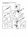
CRAFTSMAN
2500 PSI Cleaning
Pump -- Exploded View
System
580.767451
L_
C
A
L
22
CRAFTSMAN
Pump --and
Item
19
28
45
62
76
77
A
B
C
D
E
F
G
H
J
K
L
Part #
190571GS
190574GS
190578GS
190581GS
21783GS
190585GS
190594GS
190588GS
190589GS
193808GS
193806GS
190592GS
190593GS
193807GS
189971GS
193971GS
193972GS
2500 PSI Cleaning
Parts List
System
580.767451
Description
CAP, Oil
MANIFOLD
PIN
CAP
THERMAL RELIEF
OIL BOTTLE (not shown)
KIT, UNLOADER
KIT, WATER INLET, ANODIZED
KIT, OUTLET, ANODIZED
KIT, HEAD BRASS
KIT, CHECKVALVES
KIT, INLET CHECK
KIT, CHEMICAL INJECTION
KIT, SEAL SET
KIT, CHEMICAL HOSE
KIT, PIPE FITTING
KIT, UNLOADER SEAT
NOTE: Item letters A - L are service kits and include all parts shown within the box,
23
ENGINE,
6.75 HP, Briggs and Stratton,
128612 - Exploded
View
883
S
886_
584
7
993
10%)
619_
35
238 _ _
j
J
J
1029
914_
227_
_
615_
'=_
404
1022
718
505
616
25_
27o
24 [_
1102 0
1095 VALVE GASKET SET
883 _
1022
868_163_
993
51
24
ENGINE,
6.75 HP, Briggs and Stratton,
633
128612 - Exploded
View
833A @
_°_ _o_
163
276
127
95
977
CARBURETOR
GASKET
SET
276
6330
633A@
524_
25
ENGINE,
6.75 HP, Briggs and Stratton,
128612 - Exploded
65_ 58
View
121 CARBURETOR
OVERHAUL KIT
592
276_
104<
51
459 _l
689 ©
60
456
597
127_
1210
163_
3o5_
358
ENGINE GASKETSET
592 ®
332
883
12
15!A
26
137_
ENGINE,
item
1
2
3
4
5
7
8
9
10
11
12
13
15
16
20
22
23
24
25
26
27
26
29
32
32A
33
34
35
36
37
40
43
45
46
51
51A
55
58
60
65
78
95
97
104
108
109
117
118
12I
125
127
130
133
134
137
146
163
167
168
190
192
202
209
222
227
238
259
276
267
300
304
6.75 HP, Briggs and Stratton,
Part #
692670
399269
299819
498983
695276
695166
495786
272481
691125
691260
692232
691137
691680
691457
399781
691092
697586
222696
690021
694167
694168
694169
499631
692765
692766
692767
691666
499423
499424
691664
695759
499642
499641
691304
691304
694086
692194
691997
690977
694039
692666
692799
691421
692259
281434
690837
691108
691636
499682
691242
691162
693666
496976
497466
692703
694203
694466
691203
398187
398188
693961
690979
691694
691050
691147
690940
694543
691303
691290
692616
690763
691300
691169
271716
690940
697590
499676
128612 - Parts List
Description
C_(linder Assembly
Kit-Bushing/Seal (Magneto Side)
Seal-Oil (Magneto Side)
Sump-Engine
Head-Cyhnder
Gasket-Cylinder Head
Breather Assembly
Gasket-Breather
Screw (Breather Assembly)
Tube-Breather
Gasket-Crankcase
Screw (Cylinder Head)
Plug-Oil Drain
Crankshaft
Seal-Oil (PTO Side)
Screw (Engine Sump)
Flywheel
Key-Flywheel
Piston Assembly (Standard)
Piston Assembly (.010" Oversize)
Piston Assembly (.020" Oversize)
Piston Assembly (.030 Oversize)
Ring Set (Standard)
Ring Set (.010 Oversize)
Ring Set (.020 Oversize.)
Ring Set (.030 Oversize)
Lock-Piston Pin
Pin-Piston
Rod-Connecting
Screw (Connecting Rod)
Screw (Connecting Rod)
Valve-Exhaust
Valve-Intake
Spring-Valve (Intake)
Spring-Valve (Exhaust)
Guard-Flywheel
Retainer-Valve
Slinger-Governor/Oil
Tappet-Valve
Camshaft
Gasket-Intake
Gasketqr_ake
Housing-Rewind Starter
Rope-Starter (Cut to Required Length)
Grip-Starter Rope
Screw (Rewind Starter)
Screw (Flywheel Guard)
Screw (Throttle Valve)
Shaft-Throttle
Pin-Float Hinge
Valve-Choke
Shaft-Choke
Jet-Main (Standard)
Jet-Main (High Altitude)
Kit-Carburetor Overhaul
Carburetor
Plug-Welch
Valve-Threttle
Float-Carburetor
Kit-Needle/Seat
Gasket-Float Bowl
Key-Timing
Gasket-Air Cleaner
Line-Fuel (Cut to Required Length)
Screw (Control Bracket)
Screw (Fuel Tank)
Bali-Rocker Arm
Link-Mechanical Governor
Spring-Governor
Bracket-Cor'4rol
Lever-Governor Control
Cap-Valve
Bracket-Casing Clamp
Washer-Sealing
Screw (Dipstick Tube)
Muffler
Housing-Blower
Item
Part #
Description
305
691108
Screw (Blower Housing)
306
691232
Shield-Cylinder
307
690345
Screw (Cylinder Shield)
332
690662
Nut (Flywheel)
333
602574
Armature-Magneto
334
691061
Screw (Magneto Armature)
337
692051
Plug-Spark
For Platinum equivaler_-696073-use
5066, 4173, or 4174
sold in multi-packs only, Reset gap to .020")
356
692390
Wire-Stop
358
694090
Gasket Set-Engine
365
691136
Screw (Carburetor)
404
690272
Washer (Governor Crank)
443
690255
Screw (Air Cleaner Primer Base)
445
697029
Filter-Air Cleaner Cartridge
455
695161
Cup-Flywheel
456
692299
Retainer-Spring
Plate-Pawl Friction
459
281505
505
231082
Nut (Governor Control Lever)
523
499621
Dipstick
O Ring Seal (Dipstick)
524
692296
525
495265
Dipstick Tube
Grommet
529
692937
Screw (Air Cleaner Cover)
534
690244
Bolt (Governor Control Lever)
62
92613
584
692342
Cover-Breather Passage
585
691679
Gasket-Breather Passage
592
690800
Nut (Rewind Starter)
597
691696
Screw (Pawl Friction Plate)
Clamp-Hose
601
95162
Starter-Rewind
608
497680
613
691108
Screw (Muffler)
613A
691140
Screw (Muffler)
Retainer-Governor Shaft
615
690340
Crank-Governor
616
691308
619
691108
Screw (Cylinder Head Plate)
621
692310
Switch-Stop
Seal-Choke/Throttle Shaft
633
693667
Seal-Choke/Throttle Shaft
633A
691321
635
66536
Boot-Spark Plug
670
692294
Spacer-Fuel Tank
684
690345
Screw (_Breather Passage Cover)
689
691855
Spring-Priction
692
690572
Spring-Detent
718
690959
Pm-Locating
741
691630
Gear-Timing
Stud-Rocker Arm
830
694544
842
691031
SeaI-O Ring (Dipstick Tube)
843
691684
Lever-Sleeve
847
692047
Dipstick/Tube Assembly
651
493880
TerminaI-Sparkplug
868
692044
Seal-Valve
Gasket-Exhaust
683
691693
886
696268
Gasket Kit-Cylinder Head/Plate
914
691108
Screw (Rocker Cover)
921
692699
Cover-Blower Housing
Guard-Rewind
930
692691
957
692046
Cap-Fuel Tank
966
690243
Base- Air Cleaner Primer
968
692692
Cover-Air Cleaner
969
691138
Screw (Blower Housing Cover)
Tank-Fuel
972
499618
975
493640
BowFF]oat
Primer-Carburetor
976
694395
Gasket Set-Carburetor
977
692704
993
694088
Gasket-Cylinder Head Plate
1005
691346
Fan-Flywheel
1022
691690
Gasket-Rocker Cover
Cover-Rocker
1023
499624
1026
692045
Rod-Push
1029
691230
Rocker Arm
Guide-Push Rod
1034
691343
Screw/Washer Kit
1059
692311
Valve Gasket Set
1095
694091
Guide-Pilet
1102
691255
1210
498144
Pulley/Spring Assembly (Pulley)
1211
498144
Pulley/Spring Assembly (Spring)
27
28
Sears, Roebuck and Co. U.S.A. (Sears), the California
Air Resources
Board (GARB)
the United States Environmental
Protection Agency (U.S.EPA)
Emission
Control
System
(Owner's Defect Warranty
EMISSION CONTROL WARRANTY COVERAGE iS
Warranty
Statement
Rights and Obligations)
a. Fuel Metering System
APPLICABLE TO CERTIFIED ENGINES PURCHASED iN
CALIFORNIA IN 1995 AND THEREAFTER WHICH ARE
USED iN CALIFORNIA, AND TO CERTIFIED MODEL
YEAR 1997 AND LATER ENGINES WHICH ARE
PURCHASED AND USED ELSEWHERE IN THE UNITED
STATES (AND AFTER JANUARY 1, 2001 IN CANADA).
Cold start enrichment system
Carburetor and internal parts
Fuel Pump
b. Air Induction System
Air cleaner
Intake manifold
California and U.S. EPA Emission Control Warranty
Statement
Your Warranty Rights and Obligations
The California Air Resources Board (CARB), U.S.EPA and
Sears are pleased to explain the Emission Control System
Warranty on your model year 2000 and later small off-road
engine (SORE). In California, new small off*road engines
must be designed, built and equipped to meet the State's
stringent anti-smog standards. Elsewhere in the United
States, new non-road, spark-ignition engines certified for
model year I997 and later, must meet similar standards set
forth by the U.S.EPA. Sears must warrant the emission
control system on your engine for the periods of time listed
below, provided there has been no abuse, neglect, or
improper maintenance of your small off-read engine.
Your emission control system may include parts such as the
carburetor or fuel-injection system, the ignition system, and
catalytic converter. Also included may be hoses, belts,
connectors and other emission related assemblies.
c.
2.
Where a warrantable condition exists, Sears will repair your
small off-road engine at no cost to you including diagnosis,
parts and labor.
3.
Sears Emission Control Defects Warranty
Coverage
The 1995 and later small off-road engines are warrar_ed for
two years. If any emission-related part on your engine is
defective, the part will be repaired or replaced by Sears.
Owner's Warranty Responsibilities
As the small off-read engine owner, you are responsible for
the performance of the required maintenance listed in this
owner's manual. Sears recommends that you retain all your
receipts covering maintenance on your small off-reed
engine, but Sears cannot deny warranty solely for the lack of
receipts or for your failure to ensure the performance of all
scheduled maintenance.
4.
As the small off-read engine owner, you should however be
aware that Sears may deny you warranty coverage if your
small off-road engine or a part has failed due to abuse,
neglect, improper maintenance or unapproved modifications.
You are responsible for presenting your small off-read
engine to an approved Sears Service Center as soon as a
problem exists. The warranty repairs should be completed in
a reasonable amount of time, not to exceed 30 days.
If you have any questions regarding your warranty rights and
responsibilities, you should contact a Sears Service
Representative at 1-800,469-4663.
Sears Emission Control Defects Warranty Provisions
The following are specific provisions relative to your
Emission Control Defects Warranty Coverage.
1. Warranted Parts
Coverage under this warranty extends only to the parts
listed below (the emission control systems parts) to the
extent these parts were present on the engine purchased.
Inthe USA and Canada, a 24-h0ur hotline, 1-800-469-466&
maintenance information
and
5.
6.
Ignition System
Spark plug(s)
Magneto ignition system
d. Catalyst System
Catalytic converter
Exhaust manifold
Air injection system or pulse valve
e. Miscellaneous Items Used in Above Systems
Vacuum, temperature, position, time sensitive valves
and switches
Connectors and assemblies
Length of Coverage
Sears warrants to the initial owner and each subsequent
owner that the Warranted Parts shall be free from
defects in materials and workmanship which caused the
failure of the Warranted Parts for a period of two years
from the date the engine is delivered to a retail
purchaser.
No Charge
Repair or replacemer4 of any Warrar4ed Part will be
performed at no cha_je to the owner, including
diagnostic labor which leads to the determination that a
Warranted Part is defective, if the diagnostic work is
performed at an approved Sears Service Center.
Claims and Coverage Exclusions
Warranty claims shall be filed in accordance with the
previsions of the Sears Warranty Policy. Warranty
coverage shall be excluded for failures of Warranted
Parts which are not original Sears parts or because of
abuse, neglect or improper maintenance as set forth in
the Sears Engine Warranty Policy. Sears is not liable to
cover failures of Warranted Parts caused by the use of
add-on, non-original, or modified parts.
Maintenance
Any Warrar4ed Part which is not scheduled for
replacement as required maintenance or which is
scheduled only for regular inspection to the effect of
"repair or replace as necessary" shall be warranted as to
defects for the warranty period. Any Warrar_ed Part
which is scheduled for replacement as required
maintenance shall be warrar4ed as to defects only for
the period of time up to the first scheduled replacement
for that part Any replacement part that is equivalent in
performance and durability may be used in the
performance of any maintenance or repairs. The owner
is responsible for the performance of all required
maintenance, as defined in this owner's manual.
Consequential Coverage
Coverage hereunder shall extend to the faiJure of any
engine components caused by the failure of any
Warranty Part still under warranty.
has a menu of p_-recorded
29
messages offering you product
GARANTIA
....................................
INSTRUCClONES DE SEGURIDAD ..............
CONOZCA SU MAQUINA LAVADORA DE PRESION
MONTAJE ..................................
OPERACION ................................
MANTENIMIENTO
............................
GARANTIA
LIMITADA
30
30-32
. . .33
34-36
37-39
40-43
DE LA MAQUINA
ESPECIFICACIONES
............................
40
ALMACENAMIENTO
..........................
4445
REPARAClON DE DAt_OS ........................
46
GARANTIA DEL CONTROL DE EMISIONES
.........
47
COMO ORDENAR PARTES ......
PAGINA POSTERIOR
LAVADORA
DE PRESION
CRAFTSMAN
Durente un atto a partir de la fecha de compre, Sears reparer& sin cargo alguno, cualquier defecto en material y mano de
obre, siempre y cuando esta maquina lavadore a presi6n Craftsman haya sido mantenida y puesta en funcionamier_o de
acuerdo alas instrucoiones suministredas en el manual del propietario.
Siesta maquina lavadore es usada para fines comerciales, la garer_ia se aplicar,_ tan solo por 90 dias a partir de la fecha de
compre. Siesta maquina lavadore de presi6n es usada para alquiler, la garentia se apficar_ tan solo por 30 dias despues de
la fecha de compra.
Esta garantia no cubre:
Elementos perecederos
como bujias o filtros de aire, los cuales se desgastan con el uso normal.
Repareciones necesadas debido al abuso o negligencia del operador, incIuyendo daflos ocasionados por la ausencia de
suministro de agua a la bomba o por no mar_ener el equipo de acuerdo alas instrucciones contenidas en el manual del
propietario.
El servicio de garantia se hate efecfivo devolviendo
mas cercano en los Estados Unidos.
la maquina lavadore de presi6n al centro de servicio o distribuidor Sears
Esta garantia le proporciona derechos legales especificos;
estado a estado.
Sears, Roebuck
usted tambi_n puede tener otros derechos, los cuales varian de
and Co., Dept. 817WA,
Hoffman
Estates,
IL 60179
_hl
ste os
el simbolo
de alerta
Es usado
paralosindicarle
con que
peligros
potencialos
lesion
para
el personal.
Siga de
las seguridad,
instruccionos
de todos
mensajossituacionos
de seguridad
aparscen
dospuesdede
oste simbolo pars evitar posiblos Iosionos o muerte.
_Lea
oste manual minuciosamente y conozca a
rondo los partes y el funcionamiento de su
m&quina lavadors a prosibn, Conozca sus
Simbolos
de Peligro
y Significados
aplicaciones, sos limitacionos y los peligros
involucredos,
Gases T6xicos
El simbolo de alerta de seguddad (,_) es usado con una
palabre (PEUGRO, ADVERTENCIA, PRECAUCION), un
mensaje por escfito o una ilustrecibn, pare alertarlo acerca
de cualquier situaci6n de peligro que pueda exisfir.
PELIGRO indica un riesgo el cual, si no se evita, causar4 la
muerte o una herida grave. ADVERTENClA indica un riesgo
el cual, si no se evita, puede causar la muerte o una herida
grave. PRECAUCI(_N indica un riesgo, el cual, si no se
evita, puede causar heridas menores o moderadas.
PRECAUOI6N, cuando se usa sin el simbolo de alert&
Z
Superficies Resbalosas
Fu_jo
Descarga El_ctrica
5Caer
Explosi6n
Inyecci6n Lfquida
Supedicie
Caliente
indica una situaci6n que podfia resultar en el datto del
equipo. Siga los mensajes de seguridad para evitar o reducir
los riesgos de heridas e inclusive la muerte.
Partes en Movimiento
3O
Objetos Voladores
Contragolpe
:_n el estado de California es obligatorio, seg0n la lay, el usa
_e apagachispas (Secci6n 4442 del C6digo de Recurses
_0blicos de California). Otros estades pueden tenet leyes
_imiJares. Las leyes federales se aplican en tierras
'ederales. Si equipa el silenciador con un apagachispas,
_ste deber_ set mantenido en buenas condiciones de
:rabajo. Usted puede ordenar el apagachispas a tray,s de
_u distribuidor de servicio autorizado Sears.
ADVERTENCIA
CUANDC
At_ADA
COMBUSTIBLE
• Apague el generePor (posiaibn OFF) y deje_o enfdar al menos
oar 2 minutos antes de remover la tapa de la gaso,na.
I
ADVERTENCIA
El escape
del motor
elementos
quimicos
California
par producir
u otros
dafios
de este
producto
• Liana el tanoue al a=re t_bre.
• NO liana demasiado el tanque
_aexpansibn de_ ¢ombustibte
contiene
reconocidos
en el Estado de
c_ncer, defectos
de nacimiento
de t po reproduct
Permite al menos espaa=o para
• Mantenga la gaso_na alejaoa oe chlspas
c lotos, calory otras fuerffes de gnici6n,
vo.
llamas ablertas
• NO encienda un ¢lgarrilla o fume.
CUANDO
OPERE
EL EQUIPO
• NO incline el mater o el aquila,
se aueda derramar.
PELIGRO
de tal manera que la gasolma
• NO rode liquidos inflamables.
CUANDO
TRANSPORTE
O REPARE
EL EQUIPO
• Transporte o repare el equipo con e_ tanoue de combustible
ratio, o COn ta valvuta para apagar el aombusbble, apagaqa
(posici6n OFF}.
CUANDO ALMACENE
O GUARDE
COMBUSTIBLE
EN EL TANQUE
EL EQUIPO
CON
• Almacene ale|ado de calderas estufas, calentaoores de agua,
secadoras de repa u rares aoaratos electredomesticos
aue
posean p_os u arras fuentes de ignici6n, porque e_tos pueden
vapores nocivos
ertcerl(3e{"
lOS val3o_s
_e
la
gasohRa
ADVERTENCIA
ADVERTENCIA
de Io confrario podr[an oaurrir descargas ei6c_ricas f_ales
ADMERTENGIA
reaiado auando el sistema este presurizado.
ADVERTENCIA
• Ma_enga la boquilia de reaiado de 8 a 24 pulgadas de 18
s_perficie de limpieZa
• Sea extremadamente cuidadoso si usa la maqUina lavadore a
presibn desde urta escaiere, andami_ o cualquler superfic_e
re}ativamente inestable
• Ei area de limpieza ¢;ebet_ tenet inclinaciones y drenajes
adecuados para disr_inuir la posibi]idad de caidas debid0 a
Superficies resbatoSas.
• Opera Y almacene esta unidad sob_e una SUperficie estable.
• $ujete {a pistola de lahidrolavadora firmemente con ambas
manps auand0 Utilice el reciado aalta presiSn De esta manere
evitara lesiones preduc_das per el p_sibie g01pe de la pistela
hacia arras.
• Permita qua el equipo se enfrie antes de _ocarlo.
31
ADVERTENCIA
PRECAUCION
* NO asegure ia pistoia de rociado en la pos_ci6n (open =
abierto)
,, NO abandone Ja pistols de ramada cuando la m_quina est_ en
funcianamiento.
• Ate para arnba el pololargo y quite la joyeria.
NUNCA utilice Una pisto{a de rociado que no tenga Un seguro
para gati!lo o proteccibn para gatiuo en Su lugar Yen buenas
condiciones
* siempre aseg_3rese de qae Is pistols de r_ciado, boqui{las y
acoesonos esten conectados correctamente.
ADVERTENCIA
PRECAUCION
roods de rosiad0 a chsrro.
* NuNcA
no pueda entrar en contacts con la bujia
apunte is pis[ola a plan[as
PRECAUCION
• Si usted tiene a_guna pregunta acerca de las finalidades de usa
del generador, pregQntele s su conces_onano a contacte a
Sears.
ADVERTENCIA
• NUNCA deborah ser operadas las un{dades con eartes rotas o
auserrtes, o sm is caja o cublertas oe protecolon
• NO eluda ning0n dispos_t_va de seguridad
de esta maquma.
• Antes de saner en marcha la maou_na lavadora a Dresion en
slims frio. revise tadas tas patios gel equips y asegOrese de
que na se hays formado hielo sabre ella&
• Siempre Use protecc_bn pars _os ojos cuando usHce este equips
o cuando este ceres de donde se est#_usando el equips.
• NUNCA mueva la maauma nalanoo la manguera de a_ta
_resibn. Utilice la manua que wene con la un_dad.
• Revise age el s_stema de combustible no 3resente fugas o
s_gnos de detedoro, coma mangueras desgastadas o porosas,
sujetadores flo]os o ausente& taps o tandue daSados. Corrfja
todos los defectos antes de oaerar ]a m_auma _avaoora a
Dresi6n
PRECAUCION
• El equips de alta presi6n e_ d_se_ado pars ser utilizado
UNICAMENTE con las oartes autorizadas Sears. Si utiliza este
eclu{oo Con psrtes sue no cumolSn con iss esgecif_caciones
m_n{ms_ el usuar_o asame todos los nes£_o8 y
r_3DonsablJldades.
presiSn superior a su clssificaciSn de presibn
32
CONOZCA
SU MAQUINA
LAVADORA
DE PRESION
Lea el manual del propietario y las reglas de seguridad antes de porter en marcha su sistema de limpieza.
Compare {as ilustraciones con su sistema de limpieza para familiarizarse con Jas ubicaciones de los difarentes controles y
ajustes. Guarde este manual para referencias futuras.
Enjuague del Sistema Recipie_es para Quimicos y
Detergente con Filtro Interne y Divisi6n
F'eri}la selectora
DiaI-A-C{eaherT_
Pistola de Rociado
Manguera de Alta Presi6n
Taia de
Carrete de la Manguera
Filtro de Aire
Tapa del De_6sito
ael Aceite
C0ntro{ de ]a V,_lvula
de Regulaci6n
Palanca de Controt de la
V,_lvula de Regulaci6n
Extensi6n para
Boauillas
iii
Bomba
i _
_
En_rada de Agua
Toma de Alta Presi6n
Boquilla Ajustable
Arrancador de Retroceso - Usado para et amanquedel motor.
Manguera de Alta Presi6n - Conecte un extreme a la pistola
de rociado y el otpa extreme a la tema de atta presi6n.
Bomba - Desarpalla alta presi6n de agua.
Palanca de Control de la VSlvula de Regulaci6n - Coloca el
motor en mode de arpanque papa el arpancadorde retpaceso y
darlene el motor en funcionamiento.
Boquitla Ajuetable - Ajusta la presi6n a alta o baja presi6n;
rociado a chorpa o en abanice.
Carfare de la Manguera - Usado para aImacenar la manguepa
coando _aunidad no est_ siendo usada. La manguepa debera
ser descenectada de la bombay Ia pistola antes de
almacenada.
Palanca del Cebadorfr{os.
Enjuague del Sistema, Recipientes para Quimicos y
Detergente con Filtro Interne y Divisi6n - Usado papa
proporcionar detergente u otpas qu{micos a la corriente de
agua de baja presi6n.
Pistola de Rociado - Contpa{a la aplicaci6n de agua sobpa la
superficie de limpieza con el gatillo, lncluye cerpaje de
seguridad.
Usada para arranque de motopas
Perina Selecfr_oraDial_A*Cleaner TM - Se{ecciona cualquiepa de
los tpas quimicos o et enjuague del sistema de agua limpia.
Entrada de Agua - Conexi6n para la manguepa de jardin.
Tapa de la Combustible -Llene el motor con combustibIe
regular s}n contenido de plome en este punto.
Exlbensibn para Boquillas - Conectada a la pisto{a de rociado
para un use m_s conveniente.
Tapa del Depbsito del Aceite - Llene et motor con aceite
aqui. Vea la pagina 35 papa las recomendaciones del aceite y
las instrucciones de Ilenado.
Filtro de Aire - E{ elemento de filtpa tipo sece limita la
cantidad de suciedad y polvo qua se introduce en e{ motor.
Toma de Atta Presibn - Conexibn para {a manguepa de alta
presi6n.
33
Su sistema de limpieza requiere de ciedo ensemble y estar,_
lista para ser usado Onicamente despues de haber
depositado el combustible y el aceite recomendado.
Femiliericese con cede parte antes de ensambler {a
m,_quina lavadora a presi6n. Compare el contenido con la
ilustraci6n de la pagina 33. Si alguna de la pades no est,_
presente o se encuentra daCtada, Ilame ala Iinea de ayuda
de la maquina lavadora a presibn el 1-800-222-3136.
Si tiene problemas con el ensamble de su m,'Jquina
lavadora a presibn, Uame a la Iinea de ayuda de la
m&quina Iavadora a presi6n al 1-800-222-3136.
MONTAJE
LIMPIEZA
IMPORTANTE: Cualquier intento de hacer funcionar el
motor sin haber depositado el ace}re recomendado resultar,_
en falla del mismo.
RETIRE LA MAQUlNA LAVADORA
PRESION DE LA CAJA
1.
Abra la caja y code dos esquinas opuestas ala manila
guia de la parle superior ala inferior de tel forma que el
panel pueda set doblado hacia abajo.
Retire la caja del carrete de la manguera, material de
relleno y la bolsa de repuestos enviada con el sistema
de limpieza.
3.
Retire pistola aspersora, extensi6n de boquilla y ace}re
para motor de material de relleno.
4.
Saque el sistema de limpieza de la caja.
5.
Levante la manila guia, aseg0rela en su sitio.
6.
Revise la caja pare vet si existen partes sueltas
adicionales.
CONTENIDO
DE
La gran mayoria de su sistema de limpieza de presi6n
Craftsman ha sido ensamblado en la f,_brica. Sin embargo,
usted deber& Ilevar a cabo los siguientes procedimientos
antes de poner en funcionamiento su sistema de limpieza:
A
2,
DEL SISTEMA
1.
Conecte el carrete de la manguera.
2.
Deposite aceite en la caja del cig(;_er_aldel motor.
3.
Deposite combustible en el tanque.
4.
Conecte la manguera de alta presi6n ala pistola de
rociado y ala bomba.
5.
Conecte el suministro de ague ala bomba.
Montaje
del Carrete
de la Manguera
Necesitar& una la }lave inglesa de 10mm y 14mm y #2
destornillador de phillips
1. Conecte la manila el carrete utilizando tuercas de fijaci6n,
arandelas planas y pemos como se ilustra a cor4inuaci6n.
jPernos
M8
DE LA CAJA
Revise el contenido de la caja. Si alguna de las pades no
est& presente o est& daf_ada, Ileme e le Iinea de ayuda de la
m,_quina ]avadora a presi6n al %800-222-3136.
2.
Asegure el carrete de la manguera ala pade vertical del
lado izquierdo utilizando tuercas de fijaci6n y pemos.
La unidad principal - sistema de limpieza con ruedas,
tanques pare quire}cos, manubrio
Los componentes del carrete de la manguera
La manguera de alta presi6n
Pistola de rociado
Extensi6n para boquillas con boquilla ajustable a
Alta/Baja presi6n
Aceite pare motor
Boise de pades (incluye los elementos descritos a
continuaci6n)
Tres paquetes de concentrado quimico
Manual del operador
Juego de mantenimiento'
Riegue Con Una
mange !os
montes de
carrete
R{Stulos pare los tanques
Tarjeta de la matdcula
en el en_:repa_o
34
NOTA:Puede
haberalguna
ferreterfa
incluida
coneljuego
decarrete
demanga
quenoseusaenestemodelo.
IMPORTANTE:
NOuselam,_.quina
lavadora
a presi6n
teniendo
lamanguera
enrellada
enel carrete.
Elcarrete
es
Onicamente
parasualmacenamiento.
Agregue
NOTA: Revise el aeeite frecuentemente durante el
despegue del motor.
Agregue
,_
Aceite de Motor
IMPORTANTE: Cualquier intento de hacer girar o arrancar
el motor antes de que se haya depositado el aceite
recomendado puede resultar en falla del motor.
Gasolina
tPELIGRO!
NUNCA NUNCA
Ilene el tanque
combustible
en
recintos cerrados.
Ilene el de
tanque
de
combus-tible cuando el motor este funcionando o
est_ caliente. NO fume cuando est_ Ilenando el
tanque de combustible.
NOTA: Cuando agregue aceite al compartimiento del motor,
utilice Qnicomente aseite detergente de alta calidad, designado
con la clesificacJ6n API de servicio SF, SG, SH, SJ o superior,
clesiflcado con el peso SAE 30. NO use aditivos especJales.
1. Seleesione una viscosidad de acuerdo a la tabla
siguiente.
,_
IADVERTENCIA!
NUNCA
Ilene per para
complete
el
tanque
de combustible.
Deje espacio
la
expansi6n del combustible. Limpie cualquier derrame
de combustible del motor y del equipo aries de darle
arranque a la unidad.
1.
Use combustible limpio y almacenelo en recipientes
cubiertos, limpios y aprebados. Utilice embudos limpios.
Nunca utilice gesolina "vieja" dejada de la estaci6n
anterior o gesolina almacenada per periodos de tiempo
prelongados.
2.
Limpie el _rea alrededor de la tapa de Ilenado del
combustible, retire la tap&
3.
Agregue lentamente gesolina regular "SIN PLOMO" al
tanque de combustible. Use un embudo para evitar que
se derrame. Llene el tanque lentamente hasta
apreximadamente 1.5" per debajo de la parle la cima
del cuello del tube de Ilenado.
4.
Instale la tapa del tanque de combustible
gasolina que se haya derramado.
Temperaturas de Uso Esperad_s
El use de aceites multigrado (5W-30, 10W-30, etc.) en
temperatures mayores a los 40_F (4_C) ocasionar_ un
consume de aceite mayor al normal. Cuando utilice un
aceite multigrado, revise con mayor frecuencia el nivel de
aceite del motor.
** Si utiliza aceite SAE 30 en temperatures inferiores a los
40_F (4_C), ocesionara que el arranque sea m,_s dificil e
incluso que se desbiele el motor debido a su inadecuada
lubricaci6n interna.
2.
Coloque la maquina lavadora a presi6n en una
superficie nivelada.
3.
Limpie el _rea alrededor del Ilenado de aceite.
4.
Retire el tap6n del orificio de Ilenado y la vadlla de
medici6n.
5.
6.
IMPORTANTE: Es importante evitar la formaci6n de
dep6sitos de goma en les partes esenciales del sistema de
combustible come en el carburador, filtre del combustible,
manguera del combustible o tanque, durar4e su
almacenamiento. Los combustibles mezclados con alcohol
(llamados gasohol, etanol o metanol) pueden atraer la
humedad, la cual produce la separaci6n y formaci6n de
,_cidos durante el almacenamiento. La gesolina acida puede
daf_ar el sistema de combustible de un motor durante su
almacenamiento.
Limpie la vadlla de medici6n, ins_rtela en el orificio de
Ilenado y aprietela firmemente; retire la varilla de
medici6n Deposite el aceite recomendado hesta la
marea "Full" ("Lleno") de la varilla de medici6n
Para evitar problemes en el motor, deber_ vaciar el sistema
de combustible antes de periodos de almacenamiento de
30 dies o mas. Vea "Almacenamiento" en la p,_gina 44.
NUNCA use productos para limpiar motores o carburadores
en el tanque del combustible; si Io hace ocurdr,_n daSos
permanentes.
Deposite el aceite lentamente. Limpie la vadlla de
medici6n cada vez que revise el nivel del aceite. NO
Ilene excesivamente.
NOTA: Usted no puede necesitar usar rode el aceite
suministrado.
7.
y limpie la
Instale el tap6n del orificio de Ilenado de aceite y la
varilla de medici6n y aprietela firmemente.
35
Conecte la Manguera
Agua a la Bomba
y el Suministro
5.
de
IMPORTANTE: Usted deber_ armar la extensi6n para
boquil{as y conectar todas las mangueras antes de darle
arranque al motor. La bomba resultar_ daflada si arranca el
motor sin tener todas las mangueras conectadas y el
suministro agua abierto.
1. Desenrrolle la manguera de alta prasiSn y conecte un
extremo de la manguera a la base de la pistola de
rociado. Apriete con la mano.
Haga correr el agua a trav6s de la manguera de su
jardin por 30 segundos para Iimpiar cualquier escombro
que se encuentre en ella. Desconecte el agua.
IMPORTANTE: Hace NO agua de parar de siphon para el
abastecimiento de agua. Use agua SOLO fria (menos que
IO0_F).
6.
Conecte la manguera de jardin (no exceder 50 pies en
la Iongitud) a la entrada del agua. Apriete con la mano.
PRECAUCION
esta p_ecaucibn,no sera subierto per la garantfa.
7.
2.
Retire y deseche todos los tapones de transporte de la
bomba antes de conectar las mangueras.
3.
Conecte el otro extremo de la manguera de alta presibn
a la salida de alta presibn de la bomb& Apriete con la
ABRA el suministo del agua y abra la v_lvula de
suministro para purgar la sistema de bomba de aire y
impureza.
ADVERTENGIA
mano.
inspesci0ne la
rejilla de er_rada.
NO la use siesta
; Iimpiela
si se encuentra
• Antes de dade arranque a la maqUina lavadora a pres!Sn
asegQresede osar protecCibnadesuada para los ojos.
sucia:
LISTA DE REVISION PREVIA AL
ARRANQUE DEL MOTOR
Revise la unidad para asegurarse que ha Ilevado a cabo los
siguientes procedimientos:
1. Revise que los sujetadores del carrete de la manguera
est_n apretados.
4.
Antes de que conecte la manguera de jardin a la
eotrada de agua, inspeccione el colador de la entrada.
Limpie el colador si tiene residuos o solicite su remplazo
si est,_ daCtado. Refierase a la seccibn "Mantenimieoto
de los Anillos 'O'" si la colador de la entrada se daCtado.
NO haga funcionar la m_quina Iavadora a presiSn si
el colador de Ia entrada est& da_ado.
36
2.
Revise que haya sido depositado aceite y est_ al nivel
correcto en la caja del cigQer_al del motor.
3.
Deposite la gasolina adecuada en el tanque del
combustible.
4,
Revise que tadas las sonexiones de las mangueras
(alta presiSn y suministro de agua) esten apretadas
correctamente y que no existan dobleces, cortes o daf_o
de la manguera de alta presi6n.
5.
Proporcione el suministro de agua adecuado (que no
exceda los 100_F)
6.
AsegQrese de leer las secciones "Reglas de Seguddad"
y "Operacibn" antes de usar el sistema de limpieza.
COMO USAR SU SISTEMA
LIMPIEZA
DE
9.
Mueva la perilla del cebador a la posici6n "Choke".
Si tiene problemas sen el funoionamiente de su m&quina
lavadera a presi6n, per favor Ilame a la Iinea de ayuda de la
m_quina lavadera a presi6n al 1-800-222-3136.
Para Poner en Marcha
Limpieza
el Sistema
de
Para darle arranque a su sistema de limpieza mevido a
motor per primera vez, siga estas instrucciones paso a
paso. Esta informaci6n acerca de la puseta en marcha
initial tambi_n es v_lida para cuande vaya a dade arranque
al motor despu_s de habede dejade la m_quina lavadora a
presi6n fuera de funcienamiente per Io menes un dia.
1. Coleque la m&quina lavadora a presi6n en un _rea
cercana a una suministre de agua exterior capaz de
abastecer agua a un volumen mayor de 3.5 galones per
minute en no menos que 20 PSI en el fin de arandela
de presi6n de la manga del jardin.
2.
Revise que la manguera de alia presi6n se encuentre
conectada firmemente a la pistela de reciado y a la
bemba. Vea _Armade de Su Maquina Lavadora a Presi6n'L
3.
Aseg6rese que la unidad set_ nivelada.
4.
Conecte la manguera de jardfn a la entreda del agua.
Aprietela con la mane. Abra el suministro de agua.
NOTA: Si el motor set& caliente, aseg0rese que la perilla
del cebador est_ en la pesici6n "Run".
10. Mueva la palanca de la v,_.lvula de regulaci6n a la
posici6n "Fast", mareade en la unidad sen un coneje.
11. Celeque su pie izquierde en el cuadre inferior de la
unidad y sujete la manija tal y come se musetra. La
apariencia de la unidad puede ser Iigeramente distinta
de la mestrada aqui.
PRECAUCI( N
esta precauciOn; no ser_ cubierto
per la garantia.
5.
Presione el disparader en la pistela para purgar de aire
e impurezas el sistema de bembeo.
6.
Acople la boquilla de extensi6n a la pistela aspersera.
Apri_tela manualmente.
12. Jale la ¢uerda de arranque lentamente con su mane
derecha hasta que sienta alguna resistencia, entoncse
jale con energia.
13. Regrese la cuerda de arranque lentamente. NO permita
que la cuerda regrese bruscamente y golpee el
arrancader.
X
7,
8.
14. Cuando arranque el motor, mueva ]entamente la
palanca del ahogador a la posici6n "En marcha"
("Run") Si e] motor se enciende, pere no continOa
funcionande, mueva ententes la pa]anca a la pesici6n
"Ahegado" ("Choke"), y despues a la pesici6n "En
mareha" ("Run").
Coleque la bequilla en el mode de baja-presi6n (deslice
la boquilla hacia adelante) y presiene el disparador en
la pistola aspersora pera liberar la presi6n provocada
per haber abierto (ON) el agua. El agua Ilenar,_.la
pistola mediante un ligere fluje. Contin_e sesteniendo el
disparador hasta que haya un flujo estable de egua y
no quede residue algune de aire en el sistema. Suelte
entonces el disparador.
15. Si el motor ne arranca despu_s de seis tirenes, mueva
la palanca del ahogader a la posici6n "En marcha"
("Run"). Si el motor incende y ne sere mueva le
palenca a la pesici6n "Ahegado" ("Choke"), y despu_s
a la posici6n "En marcha" ("Run").
Fije el pestillo de seguridad al disparader de la pistela
aspereora.
arrancador
37
de retroceso y queef
motor no arranque.
Cemo
Detener
su Sistema
3.
de Limpieza
Mueva la palanca de la v_lvula de regulacien a la
posicien "Stop s ('ParadeS).
El patron de rociado se ajusta de un patron angosto a
un patron en abanico girando la boc uilla.
Apriete el gatillo de la pistota de rociado pare
eliminar la presibn de la manguera,
NOTA: Observera una pequefia car_idad de ague cuande
elimine la presien.
Mueva la perilla selectora Dial-A-Cleaner TM a la
posicibn OFF pare evitar la fuga del quimico.
Cemo
Usar la Boquilla
Gire la boquilia en sentido Gire
la be{ uilla en sentido de
contrari0 a{as maneci}las del
las manecillas de{ reloj para
rel0j para un patron de
un patren de rociado a
rociad0 en abanico,
oherro.
Ajustable
Usted ya debe saber come darle ARRANQUE a su m,_quina
lavadora a presien y come DETENERLA. La informaoien de
esta seccien le dir_ come ajustar el patren de rociado y
come aplicar deterger_e u otros quimicos de Iimpieza.
PRECAUCION
4.
Para una limpieza mas efectiva, mantenga la boquilla de
rociado de 8 a 24 pulgadas de la superficie de limpieza.
5.
Si coloca la boquilla de rociado demasiado cerca podria
dafter la superficie, especialmente ouando este usando
el mode de alta presien.
6.
NO coloque {a boquilla a menos de 6 pulgadas cuando
este Iimpiando Ilantas.
Trabajo de Limpieza con la Boquilla Ajustable
ef patrbn de rociado
IPRECAUCION!
Antes de darle arranque a su sistema de
Iimpieza, asegQrese de haber leido y seguido las
instrucciones de las secciones "Montaje de su Sistema de
Limpieza" y "Para Poner en Marcha el Sistema de Limpieza".
En el extreme de su pistela de reciedo existe una manija
que puede mover hacie adelante y hacie atr_s pare ajustar
el patren de reciedo para que sea de alta o beja presien.
1. Usted tambien puede ejustar el patren de reciede
girande la boquille para que este cencentrade en un
patron de cherro e un patron expandide en abanico.
IMPORTANTE: Utilice quimicos disefiados
especfficamente
pare m,_quinas lavadoras a presien. Los
deterger_es caseros podrian dafiar la bomb&
Arrancar el motor sin tene_todas las mangueras conectadas y
sin el suministr0de agUa AB(ERT0 (ON)ca_sara e! datio de
le bomba.
' Etdafio ala lavadoraa presien: resultado de la desatenoien a
esta p_..,aucibn, no sera oubierto per la garantf&
Mueva
la boq_iNa hacia
Mueva
la boquiila hacia
arras para 0btener el mode
adelante para obtener el
de alta presien,
mode de baja presien y pare
la aplicaeien del detergente.
2.
Se pueden tener hasta tres (3) diferentes soluciones en el
sistema de limpieza el mismo tiempo. Pare apNcar el
deterger_e, siga los siguientes pesos:
Apunte la boquilla hacia el suelo, desenganche el
cerroje de seguridad y apriete el gatille pare probar el
patron de reciado.
1.
Es necesario diluir los paquetes de quimices
suministrados. Tan sole torte una esquina de la bolsa
pl_stica, vierta el quimico en el tanque, despues Ilene el
tanque con ague limpia. Coloque los ferules
suministrados en los tanques correspondientes.
Vierta e{ quir!!co en uno de !os tanques
marcado con la letra A, Bi C.
2.
38
Si est_ usando c_re quimico disefiado papa use en
m_quinas levadoras a presien, prepare la solucien quimica
siguiendo los instrucdones del fabdcante del quimico. Llene
el recJpiente(s) del quTmico con la soiuci6n preparada.
3.
Gire la perilla selectora Dial-A-Cleaner TM y col6quela an
la letra que corresponda al recipiente que desea usar.
4.
Mueva la boquilla ajustable hacia adelar_e para obtener
el modo de baja presi6n. El detergente no puede set
aplicado si tiene la boquilla en Ia posici6n de alto
presi6n,
5.
sistema, permita qua dicha circulaci6n continue hasta
que deje de observar espuma de detergente.
5=
Mueva la perilla selectora Dial-A-Cleaner TM a la
posici6n OFF cuando termine para evitar Ia fuga de
quimicos,
Succi6n
de Liquidos
NO utilice agua estancada como suministro de agua. EI
agua sucia, contaminada o salobre puede daftar la bomb&
Usa Qnicamanta el suministro de agua de su casa.
Conecte la manguara de jardTn a la antrada del agua,
revise qua la manguera de alta prasidn est_ conectada
a la pistola de rociado y a la bomba (yea la p_gina 36) y
dale arranque al motor.
C6mo
Usar el Carrete
de la Manguera
Su m,_quina lavadora a presi6n est,_ equipada con un
carrete diser_ado para almacenar la manguera cuando la
unidad no estA siendo usada. Estas instrucoiones se aplican
Qnicamente para almacenamientos por un corto periodo de
tiempo. Para almacenamiento prolongado consulte la
secci6n "Almacenamiento" de la p_ginas 44-45.
ADVERTENCIA
Despu6s de cada uso:
• Mantenga ta boquilla de rociado de 8 a 24 pu_gadas de la
superficie de limu_eza.
1.
Desconecte {a manguera de la pistola y la toma de alta
presi6n de la bomb&
2.
Drene el agua de la manguera.
Despu_s de haber aplicado el dete_jente, lave la superficie
con agua a alta presi6n y despu_s enjuaguela hasta que
est_ limpia de la siguiente manera:
3.
Pase un extremo de {a manguera pot el orificio del
carrete de la manguera. Haga girar el carfare con la
manija para enrollar la manguera en el carrete.
1.
Mueva la boquilia ajustable hacia atr,:_spara obtener el
modo de alta presi6n. NO habr_ circulaci6n de quimico
si est,_,an el modo de alta presi6n.
4.
Coloque el otto extremo de la manguera en la presilla
ubicada en el costado de {a unidad.
2.
Haga una prueba en un ,_rea pequer_a de la superficie
qua va a limpiar. AsegQrese de qua el rociado de alto
presi6n no cause daf_os en la superficie.
3.
Expanda el patr6n de rociado para obtener una acoi6n
de enjuague m,_s suave. Comienca en la porte superior
del ,_rea qua va a enjuagar dirigi6ndose hacia abajo con
la misma acci6n usada para limpieza.
• Opera y almacene esta unldad sobre una su_e_cie
estable
• Sea extremadamente cuidadoso si usa la macJ_na lavadora a
presibn desde una escetera= andam_o o cualqu_e_ superflcie
retat=vamente meStable
• Sujete la p stola de la hidrolavadora firmemente con ambas
manos cuando ub/_ce el roctado a alto oresibn De esta manera
evitara lesiones _roducldas por el poslble golpe de la plstola
hacia arras.
6.
Comienca en la porci6n inferior del _rea que va a lavar
y dirijase hacia arriba, usando movimientos parejos,
largos y superpuestos.
7.
Parmita qua el dete_jente 'penatre' (entre 3-5 minutos)
antes de lavar y enjuagar. Vualva a aplicar cuando sea
necasario para avitar qua la superficie se seque.
Lavado y Enjuague
Enjuague
el Sistema
de la Superficie
Despu_s
IMPORTANTE: NO use la m,_.quina lavadora a presi6n
teniendo la manguera enroliada en el carrete. El carrete es
Qnicamente para su almacenamiento.
Sugerencias
NUNCA use la entrada de la manguera de jardin para
succionar detergente o cera.
Si tiene la boquiila de rociado demasiado lejos de la
superficie qua est_ limpiando, la limpieza no ser_ tan
efectiva.
de Cada Uso
Es muy importante que el sistema dispensador de quimicos
sea enjuagado despu_s de coda uso para evitar qua se tape
o qua presente fugas:
1.
Llene el recipiente para Enjuague del Sistema con agua
limpia.
2.
Antes de desconactar eJ suministro de agua, ponga an
funcionamier_o el sistema de limpieza.
3.
Mueva la boquilla ajustable hacia adelar_e para obtener
el modo de baja presi6n.
4.
Coloque la perilla seiectora DiaFA-Cieaner TM en la letra
que corresponda al tanque de Enjuague del Sistema. A
medida qua el agua de enjuague limpia circula por el
Siempr8 almacene el sistema de limpieza con la perilla
selectora Dial-A-Cleaner TM en la posici6n "OFF".
Sistema de Enfriamiento
(Alivio T_rmico)
Autom&tico
El agua que circula dentro de la bomba puede alcanzar
temperaturas eotre los "125"-'155_F si hace funcionar el
motor de su m,_quina lavadora a presi6n de 3 a 5 minutos
sin oprimir el gatilio de la pistola de rociado. El sistema de
enfriamieoto automatico se activa a esta temperatura y
enfria la bomba descargando agua caliente en el piso,
evitando asi el daCto intemo de la bomb&
3g
RESPONSABILIDADES
DEL PROPIETARIO
Siga el programa de mantenimiento seg_n el nOmere de horas a segOn el calendario, Io qua suceda primere. Se requiere
de servicia con mayor frecuencia cuando opera la unidad en }as condicianes adversas descritas a continuaci6n
HORARIO DE MANTENIMIENTO
COLOQUE LAS FECHAS A MEDIDA QUE VA
COMPLETANDO EL SERVIOlO REGULAR
INTERVALO
DE OPERACION
PaR
HORA
FECHAS DE SERVIClO
I
Antes de
cada usa
TAREA
MAQUINA
Cada 25
Horas o
Anualmente
Cada 50
Horas _
Anuelmente
Oada 100
Hares o
Anualmente
DE MANTENIMIENTO
LAVADORA
A PRESION
Revise/limpie el colador de la entrada
de agua de la bomba
X¢
Revise la manguera de alta presi6n.
I
Revise la manguera del detergente
I
Revise la pistola de rociado y el conjunto.
E rnnee arey as centamnar_esde a bornba.
x
x
X
Cambio del aceite de la bomb&
MOTOR
Revise el nivel de aceite
Preporcione
I
servioio al depurador
X
de aire.
x*
Cambie el aceite del motor.
Remplace la buj[a.
Preporcione servioio al apagaohispas.
X
Prepare la unidad para almacenamiento.
IPrepar_ la unidad
psra almacenarniento 8i va a
I estar fuera de ser_cio par m_s de 30 dias.
I
1" Limpiar siseta
obstruido.
Remplazar
si est_ perforado o rata.
Cambiar el aceite despu6s de las primeras (5) hares y despu6s cada 50 horas. Hacer el oambio de aceite con mayor
frecuencia cuando trabaje en condiciones
**
Remplazar
mas a menudo bajo condiciones
ESPECIFICACIONES
PRODUCTO
Especif!caciones
a I-resion
de suciedad o polvo.
DEL
RECOMENDACIONES
GENERALES
La garantia de la m,_.quina lavadora a presi6n NO cubre los
elementos que han sido sujetos a abuso o negligencia par
parte del operador. Para hacer v&lida la cobertura total de la
garantia, el operador deber,_ mantener la lavadora de
presi6n tal y coma se indica en el manual, incluyendo su
adecuado almacenamiento, coma se describe en la secci6n
"Almacenamiento" en la p,:_gina 43-44.
de la M&quina Lavadora
Presi6n ..................
Velocidad de flujo ..........
Mezcla de quimicos ........
Temperatura del suministre
de agua .................
Peso que Embarca .........
Especificaciones
de rnucha suciedad o polvo.
2,500 PSI
2.5 GPM
Use segQn instrucciones
Algunos ajustes tendr;_.n que hacerse peri6dicamente para
mantener adecuadamen[e su m_quina }avadora a presi6n
Que no exceda los fl00_F
102 Ibs.
Todos los servicios y ajustes deborah hacerse par Io menos
una vez en cada estaci6n. Siga las instrucciones de la tabla
"Programa de Mantenimiento" descrita antedormente.
del Motor
Caballos de fuerza .........
6.75 HP
Bujia
Resistor ................
Champion RC12YC
Platino de Larga Duraci6n .Champion RC12PYP
Calibre la separaci6n a: ...0.020 pulgadas (0.50 ram)
Capacidad de gasolina ......
1.6 Cuartos
Aceite ...................
Par encima de 40_F .... SAE 30
OaF- 40_F ...........
SAE 5W-30 o 10W-30
NOTA: Una vez al alto, usted deber,_ }impiar o remplazar la
bujia y el filtro de aire. Una bujia nueva y un filtre de aire
limpio garantizan una mezcla de combustible-aire adecuada
y le ayuda a su motor a funcionar mejor y a tenor una vida
Qtil mas prolongada.
Si equip6 con Ilantas que se pode hinchar, mantenga la
presi6n a_rea en el valor marcado en la Ilanta o dentro de
15 y 40 psi.
40
ANTES DE CADA USO
1.
Revise el hive{ de ese{te de{ motor.
Revise sf exdsten de_os en el coledor de la entrade de egua.
Revise si existen fugas en le manguepa de elta presi6n.
Retire le pistole y la extensi6n pare boquillas de le
manguepa de alta presi6n. Retire la extensf6n pare
boquillas de la pistola y retire el anillo 'o' y el colador de
la extensi6n pare boquillas. Lave el colador, pfstole y
extensi6n pare boquillas con ague Iimpie papa eliminer
tode erase de residuos.
Revise si existen daftos en los filtros y tanquse de quimicos.
Revise si existen fugas en el conjunto de la extensf6n
para boquillas y pistola.
2. Si el colador est_ def_ado, encontrar& un colador pare el
filtro en Iinee y un anilfo 'o'de repuesto en el juego de
enillos 'o'. SI no est_ daftado, vuelve a usar}o.
Elimfne el aire y los contemfnantes
3. Coloque el coledor del filtro en Iinea en el extremo con rosca
de le extensi6n papaboquilles. Su direcci6n no importa.
Coloque el coledor ejerciendo presi6n con el bomador de un
I_piz hesta que se asiente por completo en el rondo de le
ebertupa. Tenge cuidado de no doblar el colador.
de le bomb&
MANTENIMIENTO
DE LA MAQUlNA
LAVADORA A PRESION
Revise y Limpie el Colador
de Entrada
4.
Examine el colador de entrada de la manguepa de jardin.
Limpielo si est,_ tepedo o remplacelo siesta roto.
Revise
la Manguera
Coloque el anillo 'o'en la renupa respectJva. Empuje el
eniflo 'o' hasta que quede ejustado contre el colador del
filtro en Iinea.
5. Conecte la extensfbn papa boquillas e le pistole de rociedo
de le manepa descrfta enteriormente en este manual.
de Alta Presi6n
Elimine
Bomba
Las manguepas de alte presi6n pueden desarrollar fugas
debido el desgaste, dobleces o abuso. Revise la menguepa
antes de cede uso. Revise si existen cortes, fugas,
abpasiones, levantemiento de la cubierte, daf_o o movimiento
de los acoplamientos. Si existe cualquiepa de estes
condiciones, remplace le manguepa inmediatamente.
el Aire y los Contaminantes
Pare retirar el aire de la bomba, siga los siguientos pasos:
1.
Instale el sisteme de limpieze como est,_ descrito en
"Montaje Del Sistema Limpieza" y conecte el suministro
de egua.
2.
Hale el gatillo de la pistola y mantengalo apretado haste
que obtenga una corriente de ague constante.
ADVERTENCIA
Pare retirar los contaminantes
siguientos pesos:
los Recipientes
de los Quimicos
de Ia bomba, siga los
1.
Instale el sisteme de limpieze como est,_ descrito en
"Montaje Del Sistema Limpieza" y conecte el suministro
de egua.
minima de presi6n de su m_quina tavadora a presi_n.
Revise
de la
2.
Retire el ecoesorio papa boquillas de la pistola.
Las cubiertas de los tanques deben ajuster firmemente en el
tanque. AsegQrese que los r6tulos de los quimicos
identifiquen correctamente el contenido del tanque.
AsegQrese que el tenque de Enjuague del Sistema est_
Ileno con agua limpia. Aseg0rese que le perilla selectora
Dial-A-Cleaner TM gire sin problemas entre posiciones.
Examine los tenques y remplece si el filtro esta tapado.
3.
Ponga en marcha el motor de ecuerdo e les
instrucoiones de "Como User Su Sistema De Limpieza ".
Revise la Pistola
Boquillas
Mantenimiento
y la Extensi6n
para
Hale el gatillo de la pistola y mantengalo
5.
Cuando el suministro de egua sea uniforme y
constente, engenche el cerrojo de seguridad y vuelva e
ajustar el acoeserio pare boquilles.
apretado.
de la Boquilla
Si sier_e une sensaci6n pulsente el momer_o de epretar el
gatillo de le pistola rociadopa, puede que sea ceuseda pot la
presi6n excesiva en le bomba. Le cause principal de la
presi6n excesiva en le bomba es cuando la boquille se
encuentra etascada o tepada con materieles extraflos, tales
como tierre, etc. Papa corregir el problem& limpie
inmediatamente la boquille las instrucoiones siguientes:
Examine le conexi6n de le manguepa ale pistole y
cerciorese de que este en buen estado. Pruebe el gatillo
opdmiendolo y asegur_ndose de que se devuelve e su sitio
cuando Io suelte. Coloque el cerrojo de segurided en la
posicidn UP y pruebe el gatillo. Usted no debe set capez de
opdmir el gatillo. Remplace le pistole inmediatemente si felle
cualquiepa de estas pruebes.
Revise el Filtro en Linea
Consulte la ilustraci6n y suministre servicio el filtro en linee
si se tape siguiendo estos pasos:
Extensi6n pare boquillas
4
Anill_
41
1.
Apague el motor y epague el suministro de ague.
2.
Remueva la boquilla del extremo de le extensi6n de le
boquilla. Separe le extensibn de le boquille, de la pistola
rociedora. Gire la boquilla en diresei6n de les egujas del
reloj, ala posici6n "stream" (chorro). Usando un Allen
de 2ram (5/64) provista, remueva la boquilla del
extremo de la extensi6n de la boquilla.
3. Quiteel en
el filtre de la Iinea del otro fin de la extensi6n
NOTA: Los dos anillos 'o' antedores tienen un tamafio
similar. Pot favor comp_relos y aseg_rese de usarlos an el
lugar correcto.
de boquilla.
4. Usa el alambre incluido en el juego (o un pequefio sujeta
papeles) para liberar cualquier matedal extrafie que este
tapande la bequilla.
t celader para la entrada de agua (pin B2384) para el
conecter de la manguera de jardin.
5. Usande una manguara de jardin, ramuava cualqufer
desecho adicional, ponfendo agua en la extensi6n de la
boquilla. Haga 6sto de 30 a 80 segundos. Gire la
extensi6n de la boquilla ajustable a "stream spray"
(chorre rocfador) y muava la boquilla de "low" (baje) a
"high" (alto), mientras drone el agua.
Para reUrar un anillo 'o' desgastado o dafiado:
UtJlice un destomillader de cabeza plana pequefie, colSquelo
pot debaje del anille 'e' y s_quelo hacienda palanc&
Cambio del aceite de Ia bomba
MANTENIMIENTO
DE
LA
Cambie
el aceite cada 50 hot'as
o una
vez BOMBA
al afio, Io qua
suceda antes.
NOTA: Debe adquirir una botalla de acaite para la bomba
previameote medido, N_ de plaza 190585GS, Ilamando al
1-800-366-PART o an linea en www.sears.com.
6. Instale de nuavo la boquilla yen el filtre enqinea en la
axtansi6n. NO la apriete demasiado con la Ilave Allen.
7. Conecta de nuavo la axtansi6n de la boquilla a la pistola
reciadora.
Cambie el aceite como se indica a continuaci6n:
8. Conecta de nuavo e{ sumfn{stre de agua, prenda el agua,
y encienda el motor.
1.
Vacfe el aceita del motor y el combustible
Iimpiadora a presi6n.
g. Pruebe el lavador a prasi6n al hacer funcionar la boquiila
an la posici6n "high" y "low".
2.
Usa una 8mm Ilave allan para extract el tap6n negro de
acaite de la bomba que hay entre la salida de prasi6n y
la entrada de la manguera de riego.
Mantenimiento
de los Anillos
'o'
Duraote la operaci6n normal de su sistama de limpiaza los
anillos 'o' mantienen apretadas y libres de fugas las
conaxiones de {as mangueras y la pistola. EIIos puaden
desgastarse o dar_arse con el use. Su sistama de limpiaza
viene con un Juego de Mar4animiento para anillos 'O', el cual
contiene anillos 'o', una arandela de caucho y un colador de
repuesto para la entrada de la manguera de jardfn.
i ::_,
de la
_- Tap6n de
Aceite
/
_
Las partes del Juego de Anillos 'o'incluyen:
1 anillo 'o' rejo, (pln B2726) para el extremo de la
conexf6n de la pistola de reciado entre la pistola y la
extensi6n para boquillas.
t anillo 'o' amarillo, (pin B2264) para el extremo de la
manguera de alta presi6n.
3.
Incline la limpiadora a presi6n hacia un lado para qua
vaciar completamente la bomba de aceite, y vierta este
en un recipiente homologado.
4.
Incline la limpiadore a presi6n hacia el lado contrario y Ilene
la bomba con el aceite recomendado a traves del mismo
orifido (puede utilizar para ello un embudo pequefio).
5.
Instale el tap6n negro de aceite de la bombay
firmemente.
6.
Coloque la limpiadora de presi6n en su posici6n normal
(de pie). Aflada combustible y aceite de motor.
MANTENIMIENTO
Revisi6n
apri_telo
DEL MOTOR
del Nivel del Aceite
El nivel del aceite debera sar revisado antes de cada use o al
menos cada 5 hot'as de operaci6n Conserve el nivel del aceite.
42
Cambio
de Aceite
Cambie el aceite del motor despues de los primeres 5 horas y
coda 50 horas, o anualmente, a partir de ese momento. Si
esta utilizando su maquina lavadora a presi6n bajo
condiciones de extrema suciedad o polvo, o en un clima
demasiado caliente, haga el cambio de acoite coda 25 horas.
PRECAUCION
3.
Para limpiar cartucho, utiliza suavemente el lado plisado
de papel en una superficie plan&
4.
Instale limpie (o nuevo) limpiador de aire en la base. El
limpiador aereo debe quedar seguramente en base.
5.
La cubierta del lugar sobre limpiador de aire y aprieta
los tornillos.
Remplace
la Bujia
Remplace la bujia anualmente o coda 100 horas de operaci6n.
1.
Limpie el _rea alrededor de la bujia y retirela.
ADVERTENCIA
• Completamente
lavado expuso Areas con el jab6n y elagua.
NINOS, NO CONTAMINE CONSERVE los
RECURSOS, VUELVA ACEITE USADO A la
ANTENGA FUERA
DE ALCANCE DE
ICOLECCION
CENTRA,
_
Cambie el aceite con el motor caliente despu6s del
funcionamiento, como se indica a continuaci6n:
no pueda
entraren contactoconfa bujfa.
Retire el tap6n del drenaje ubicado en la porte inferior
del motor.
Drone el aceite en un recipiente adecuado. Cuando la
caja del cig0efial est6 vacia, vuelva a colocar el tap6n
del drenaje.
2.
3.
Retire y revise la bujia.
3.
Depesite el aceite lentamente por la abertura de Ilenado
del aceite. Vuelva a colocar y a apretar la varilla de
medicidn, retirela y revise el nivel del aceite. El nivel del
aceite debe estar en la marco de "Full" (_Lleno") de la
varilla de medici6n. NO Ilene pot encima de esa marco.
4.
Revise la separaci6n del electrodo con un calibrador de
alambre y ajuste la separaci6n a 0.020 pulgadas
(0.50 mm), si es necesafio.
4.
Instale y apriete la varilla de medici6nltapa del aceite
cuando la caja del cig0efial est6 Ilena al nivel correcto.
5.
Limpie los residues de aceite.
5.
Instale la bujia y aprietela firmemente.
1.
2.
Servicio
del Depurador
de Aire
Su motor no funcionar,_ adecuadamente y puede dafiarse si
usted Io hace funcionar con un depurador de aire sucio.
NOTA: Puede adquidr nueves bujia al n0mero telef6nico
1-800-366-PART.
Suministre servicio al depurador de aire una vez coda
I00 horas de operaci6n o una vez por afio, Io que suceda
pfimero. Suministre servicio m,_s frecuer4emente si la
unidad funciona bajo condiciones de mucha suciedad o
polvo. Los repuestos se encuentran disponibles en su centro
de servicio local Sears.
Carburador
Si usted cry. que su carburador necosita ajuste, visite su
contro de servicio Sears m&s cercano. E{ funcionamier_o del
motor podda resultar afectado a altitudes pot encima de 3000 a
5000 pies. Para operaciones a elevaciones mayores, pSngase
en cort_acto con el contro de servicio Sears mas cercano.
Para suministrar servicio al depurador de aire, siga los
siguientes pasos:
1.
Para el uso del reemplazo o el bujia uniforme de la
chispa de re6stato, el Champion RC12YC o el bujia
largo de la chispa de platino de vida, el Champion
RC12PYP.
Servicio
Afloje dos tornillos y levante lejos cubierta.
del Apagachispas
El motor de su unidad no viene equipado de f_brica con un
apagachispas. En ciertas _reas, es ilegal operar motores
que no tengan apagachispas. Revise los leyes y
regulaciones locales. Si necesita apagachispas, Io puede
comprar en su centro de servicio Sears m&s cercano. Para
obtener el n_mero de parte Ilame al 1-800-366-PART.
Dos Tornillos
Deber_ suministrarle servicio al apagachispas coda 50 horas
para conservarlo en buenas condiciones de funcionamiento.
Cartucho
Si el motor ha estado funcionando, el silenciador estar_
bastante caliente. Deje que el silenciador se enfrie para
poder darle servicio al apagachispas.
2.
Retire cuidadosamente
Retire la pantafla del apagachispas para limpieza e
inspecci6n.
Remplace la pantalla si est_ dafiada.
aire Iimpiador de la base.
43
DESPUES
DE CADA use
ALMACENAMIENTO
INVIERNO
NO deber,_ haber ague en le unidad per la_os periodos de
tiempo. Los sedimentos de minerales se pueden depositer
en partes de le bombe y "congelar" su funcienamiento. Lleve
a cabo estes procadimientos despues de cada use:
1.
Lave el sistema de quimicos selecoionande el tanque
de enjuague del sistema y haciende funcienar {a
m,_quina lavedere a presi6n con le boquille en el mode
de beja presi6n. Lave per un minute e haste que se
haya eliminado el quimico del sistema.
2.
Apague el motor y d_jele enfrier, despu_s retire redes
los mangueras.
Desconecte el alambre de le bujie.
3.
4.
5,
6.
7,
8,
PRECAUCI6N
Pare proteger la unidad de las temperatures
congelamiento:
Seque redes los Hquidos de {a bemba halando la manija
de retrocase epreximadamente 6 vecas. Este deber,_
evecuar la mayoria del Hquide de {a bemba.
Gire la perilla selectera Dial-A-Cleaner TM e la pesici6n
OFF.
1.
Enrolle {a manguera de alta presi6n y revisele pare ver
si presenta defies. Los cortes en la manguera e el
desgaste de {a misma pueden ocasienar fuges y
p_rdida de presi6n. Si encuentra elgQn defoe, remplaca
le manguera. NO intente reparer una manguere
daCtada. Remplaca le manguera con la porte Craftsman
genuine.
Desconecte {a manguere de la pistela y {a tome de cite
presi6n de le bombe. Drone el ague de {a manguere,
pistole, y extensi6n de le boquille y limpiele con un
trope.
Peso un extreme de {a manguera per el erif_cio del
carrete de le manguera. Haga girar el carrete con {a
manija pare enrollar le manguera en el carrete. Coleque
el otre extreme de la manguera en le presille ubicada
en el costado de le unidad.
combustible
en el tanque
en recintes
en
tADVERTENCIA!
NUNCA
elmacenecerrades
el motoro con
;Jreas encerrades con pose ventilaci6n dende los
vapores puedan entrar en contacte con llamas
ebiertas, chispas o luces de piloto.
44
de
Vecfe redes los recipientes de quimicos de le siguiente
manera:
e
Desconecte le menguere conecteda el adeptador de
inyecci6n de quimicos de le bomba. Coloque el
extreme de le menguere en un recipiente edecuedo.
b.
Mueve la perille selectora al Tanque A y abra le
cubierta del tanque. La fuerza de grevedad se
encarger_ de veciar el contenido del tenque en el
recipiente.
c.
Cuendo el tanque este vecio, repita el paso (b) pare
los tanque B y C, utifizando un recipiente diferente
pare cada quimico.
d.
Vuelva a conectar le manguera el edeptador de
inyecci6n de quimicos de le bomba. Ar_ade 0.5 litres
de ague fimpie e cada tanque y cierre las cubiertas
de los tanques.
2.
Enjuague el sistema de quimicos selecoionando un
tanque y penga en funcionamiento la m&quina lavedora e
presi6n con le boquilla en el mode de beja presi6n.
Eniuague haste que cede tanque est_ vecto, despu_s
mueva le perille selectora al siguiente tanque. El _ltimo
tanque que se debe veciar es el tanque de Eniuague del
Sistema.
3.
Utilice un protector de bomba, dispenible en Sears con
el nQmero de cat&logo 7174403, pare cuidar la bemba.
Aqu_l protege ala unidad centre el congelamiento y
lubrica tanto los pistones come los empaques.
4.
Si el protector de bemba no est& disponible, conecte un
tramo de 3 pies de manguera de jardin ala er_rada de
ague. Vierta anticongelante RV (anticongelante sin
alcohol) en la manguera. Jale la manija de arranque
dos veces. Desconecte despu_s la manguera de 3 pies.
9. Vuelve a conectar el alembre ala bujia.
10. Almacane el sistema en una ;Jree limpie y seca.
,_
PARA
ALMACENAMIENTO
PROLONGADO
Protecci6n
A protege al salvador de bemba de use de bomba Sears a
previene congelar el daf_o y lubrica _mbelos y selles.
Si usted no planee usar la m,_quina lavadera a presi6n per
m,_s de 30 dias, deber_ preparar el motor para un
almacenamiento prolongado.
NOTA: EI protector de la bemba, n_mere de item Sears
nQmero 7174403, estAn disponible s61o come un acceserio
opcionaL No es incluido con la arandela de la presi6n.
Es importante evitar la formaci6n de dep6sitos de gema en
las partes esenciales del sisteme del combustible tales
come carburader, filtro del combustible, manguera o tanque
del combustible durante el almacenamiento. Tambi6n, la
experiencia indica que los combustibles con mezclas de
alcohol (llamados gasohol, etanel o metanel) pueden atraer
la humedad, le que Ileva a la separaci6n y formaci6n de
,_cidos durante el almacenamiento. La gasolina _cida puede
daf_ar el sistema del combustible
almacenamiente.
Proteja
el Sistema
de la Bomba
PREGAUGION
de un motor durante el
congelamiento.
AI use el salvador de bomba:
de Combustible
PRECAUCION
Aditivo para Combustible:
Si va a usar aditivo para combustible, Ilene el tanque de
combustible con gaselina fresca. Si el tanque est,_
parcialmente Ilene, el aire del tenque va a premover el
deteriere del combustible durante el almacenemiente. El
motor y el combustible pueden ser almacenades hasta
24 meses con aditive.
1.
Conecte manga en el salvador de bomba puede a la
cala de la bomb&
2.
EI empuj6n en puede la cima a distribuye bomba
salvador.
Deposite el aditivc para combustible siguiendc las
instrucofcnes del fabricante.
3.
Aseg_3rese de tenet cenectade y ABIERTO el suministre
de agua a la entrada de la bcmba.
Cu,_nde liquido de salvador de bomba comienza a la
salida de la bomba de la salida, la bomba es protegida.
4.
Quite bemba salvador de la cala de bomb&
* Siempre protecciSn de ojo de use Cuando se usa PumpSaver.
Ponga en funcionamiento el motor en un _rea
descubierta per 10 minutes para asegurarse de que la
gasolina tratada ha remplazado la gasolina no tratada del
carburador.
OTROS
NO almacene gasolina de una estaci6n a otra.
Si es posible, almacene su unidad en un recinto corrado
y cObrala para protegeda del polve y la suciedad.
ASEGURESE DE VACIAR EL TANQUE DEL
COMBUSTIBLE,
Si no usa aditive para combustible, retire todo el
combustible del tanque y haga funcionar el motor hasta que
se detenga per falta de combustible.
Cambio
IMPORTANTE: NUNCA cubra su m,_quina lavadora a
presi6n cuande el motor y el ,_rea del escape est_n
calientes.
de Aceite
Con el motor todavia caliente, drene el aceite de la caja del
cigQer_aL Vuelva a Ilenarlo con el grade de aceite
recomendado. Vea "Cambie de Aceite" en la p,_gina 42.
Aceite el Di&metro
Interior
del Cilindro
Retire la bujia. Rocie apreximadamente 1 onza de aceite
limpio para motor dentre del cilindre. Cubra el orificie de
la bujia con un trape. Hale la manija de retrecese
lentamente para distribuir el aceite. Evite el rociado del
erificio de la bujia.
Instale la bujia NO conecte el alambre de la bujia.
45
Soluci6n
I
2_
boquilla est& en e{ modo de baia
l.
Mueva ]a boquiJla haoia atr_s para el
modo de alto presi6n.
La entrada de agua est& bloqueada.
2.
Cimpie !a entrada:
3.
Proporcione flujode
4.
Es[im la mangqera de entrada, c01oque
Un parohe en ]a fuga.
3:Suministr0
La bomba presenta los
siguientes problemas: no
produce presibn, prodUCe una
presi6n errada, traqueteo_
p6rdida de presibn_ bajo
volumen de agua.
El detergente no se mezc|a
con el rociado,
El motor funciona bien
cuando no tiene cargos, pete
funciona "mal" cuando se
conecta una cargo,
aguaadeouado.
4;
La manguera de er_rada estA
doblada o presenta fugas,
&
El colador de la manguera de en_rada 5.
est,_ tapads,
Revise y limpie el coladQr de la
manguera de entrada;
&
El suministro de aguaesta
encima de 10s "100_F.
Proporcione suministro de agua m_s fria.
71
La manguera de aita presi6n est,_
bloqueada 0 presenta fugas,
7.
81
La pist01a presenta fuga s
8.
Remp]ace !e Pistola.
9.
boquilla est& obstruida.
9.
Limpie la b0quilla.
por
6.
Retire los obstrucciones
de salida.
de la manguera
10, Bombadefectuosa
10: P6ngaseencontactoconelcentrode
servicio Soars.
1.
La linea detergente se ha obstruido o
est_ dobiada.
1.
Repare o remplace la iinea del
oetergente.
2.
EI fiJtro oel Tsnoue oe los oulm_cos
est,_ tapaoo.
Sucio en el f]ltro de la line&
2.
Remp_ace el tanoue,
3.
Vea "Cheque En el Filtro de la Linea".
4.
La boquilla est& en el modo de alto
presiOn
4.
Mueva la boouilla hacia ade{ar4e Data el
modo de baa presi6n
5.
La peril}a Dial-a-Cleaner
posioi6n de apagado
5.
Gire la perilla a la posioi6n del quimmo
aue desea.
3.
TM
est& en la
La velocidad del motor es demasiado
lento.
1.
El motor no arranca; o
arranca y funciona real
de aguainadecuadO:
Mueva e/control de la v_lvula de regulaci6n a
a posici6n FAST (RAPIDO). Si e/motor
continua funcionando real, p6ngase en
contacto con elcontro de servicio Sears,
Deourador de aire suoio.
1.
Limpie o remplaoe el deourador de aire.
2.
Sin gasolina.
2.
Llene e] tanoue de combustible.
3.
Gasolina vieja.
3.
Drene el tanoue oe gasolina
combustible fresco.
4.
El alambre de la bujia no esta
conectado a la bujTa,
4.
Conecte el alambre a la bu_ia.
5.
Bujfa mala.
5.
RempJaco la bujia.
6.
Agua en la gasolina.
6.
Drene el tanoue oe gasolina: llenelo con
combustible fresco.
7.
Estrangulaci6n
7.
Abra el cebador pot completo y haga
girar el motor.
8.
Mezcla de combustible
rico
8.
P6ngase en contacto con el centro de
servioio Sears.
9.
V&lvula de er_rada trabada en la
oosioi6n abierta o oerrada.
9.
P6ngase en oontaoto con el centro de
servioio Sears.
excesiva.
demasiado
Ilene/o con
10. El motor ha perdido compresi6n
10. P6ngase en contacto con el centre de
servicio Sears.
El motor se apaga durante la
operacibn.
Sin gasolina.
Llene el tanoue de combustible.
El motor no tiene fuerza.
Fimtrode aire sucio
Remplace el filtro de a_re,
El motor intenta estabilizarse
o su funcionamiento no es
constante,
Cebador abierto demasiado r'&pido
Mueva elcebador a la posici6n intermedia
nasta oue elmotor funcione normalmente.
46
Sears, Roebuck and Co., U.S.A. (Sears), California Air Resources Board (Consejo de Recursos sobre el Airs de
California, CARB, pot sus siglas en ingles) y United States Environmental Protection Agency (Agencia de Protecci6n
Ambiental de EE.UU., EPA, pot sus siglas en ingles).
Declaracibn de garantia del sistema de control de emisiones
(derechos y obligaciones del propietario pare la garantia contra defectos)
LA COBERTURA DE LA GARANTIA DE CONTROL DE EMISIONES SE
APLICA A LOS MOTORES CERTIFICADOS ADQUIRIDOS EN
CALIFORNIA EN 1995 Y POSTER_ORMENTE, QUE SE UTIUCEN EN
CALIFORNIA, Y A MOTORES CERTIFICADOS MODELS 1997 Y
POSTERIORES QUE SEAN ADQUIRIDOS Y UTILIZADOS EN OTRA
REGION DE ESTADOS UNIDOS (Y A PARTIR DEL 1° DE ENERO DE
2001, EN CANADA).
de emisiones} en la medida qua dishes parses hayan estads
presentes en el motor adquiddo.
a
Sistema de medici6n de combustible
Sistema de enriquecimiento pars arpanque en frio.
b
Dealersci6n de garantia sobrs el control de emisiones de la EPA de
EE.UU, y California.
Filtro de aipa
Colecpar de entrada.
El California Air Resources Board (CARB), la EF'A de EE UU y Seers es
comptacen en expiicar la Gapantia pare el sistema de control de emisiones
pare motorss paque_ce pars exteriores (SORE) modetos a_la 2000 y
posteriores En California, los ceevce motorss boquefies pare exleriores es
debon dieafpar,constrsir y bou=par pare cumplir con les estoctas normes
del estado esntrs el smog En arras regiones de Estadce Unido& tos
ceevce motores pare interiorss de ignici6n per chispa certificedce papa
modelce a_o 1997 y pesparioresdeben eumplif COnnormas simileres
estableeides par le EPA de EEUU. Sears debe gapantizar el sistema de
control de emisiones de su motor pare Ice perfodos indicedes a
continuaci6n, siempre y cuando no se haya abueado, deesuidedo s dabs
mentenimiento iceorpacto el motor per4ueSopare e×ieriores
c
d
e
de Sears
eontra
defactes
en el control
2
dsl propiatario
de
3
dei motor peque_o
papa e×teriapas,
usted
Reclemea
y exclueionea
de eobettura
LOS Paclamos vinsulades con le gepantia ea prsesnl:ar_n cenforme a
les disbosiciones
de la P_lize de gapantia de Sears. La esborturs de
la gepantia es excluir_ papa aquelles Pallas de pa_es gepanlizades
qua no esan partes originales de Seers e debido a ebues, dessuido
o mentenimiento
inesrrecto, eagQn es e_eblece
en le P(_lize de
gapantfe de metorss de Seers Seers ne es respesesble
per le
esbortupa de Pallas de partes gapantizedas
ocasionadas
per el ues
de partes adicieseles,
no bogineles e modificedes
siemppa
debe tenet en cuenta qua Sears podr_ neger la cebertupa de le gapant[e
si au motor peque_o pars exteriopas o una paris del raisins presenta
Pallas debido a abuse, descuido,
mentenimiento
inesrpasto e
modificaciones
no eprobades
5
Mantanimien_
Cualquier parte gapantizada cuyo reamplaea no este progpamada
esmo mantenimiento requetido o que este progpamada boicamente
pare inspec_On frecuente con el fin de "reparar o reemplazar
esnforme aea necesado", estar_ gapantizada en cuanto a depactce
par el perfodo de la gapantfa Cualquier perle gepantizada euyo
reamplaea este progpamado coma mentenimiento requetido tendr_
eslamente una gapantia contpa defecpas _nicemente bar el periods
haste el primer reemplazo pragpamado pare esa parte. Se bodr&
utilizer cualquier parte de repuesto que tangs un rendimients y
dupabilidad equivalentes, al realizer cualquier actividad de
mantenimiento o repapaci6n El propietario es responaable de
realizer rods el mantenimiento requerido, aeg0n ea define en este
manual del propietaria.
Usted es resboneabie de presenter su motor pequet_o pare exteriores a
un Centro de earvicia Sears aprobedo tan pronto come es presents el
problema Les repepaciones bajo gapantfa deber_n concluirse en un
periods rszonebie, que no exceder& de 30 dies
Si tiene algun8 pregunta con respects a sus derechos y
responeabitidades pare la gapantia, p6ngese en esntac_o con un
representante de servicio Sears el 140048g4663
Disposicionea de le garent|a de Sears centre defectos en el control
de ernisionea
Les siguientes son dispceicianes especificas relacianades can la
cebertupa de le gepantie centpa depacpasen el control de emisiones
1.
NO habr_ cargos
pare le garentie
4
ppapietario
Vigeacie de la coberture
La repapaci6n o reemplazo de cualquier parts gapantizada es
realizar_ sin cargo algeao papa el propietario, induyenbo
la mane de
obpa de diagn_s_es qce derive en la determinesi¢_n de qua une paris
gerantizede
est_ depactuoea, ai la labor de diagnOstice se realize en
ce Centrs de esrvicio Seers eprobado.
Coma propietaria dei motor pequef_o pare exteriapa& usted es
rsaponaeble de realizer lea ectJvidades de man_enimiento
requerides
qua es indicen en este manuel del propietario. Seers Pacemienda qua
conserve todce Ice recibes qua subpan el mantenimiento
de su motor
boque_o papa exterparsa, pars Sears no puede negar le gepantia
eslemen_e per la Pal_ de recibce ni per su imposibilidad
de gepantizer la
rselizesi6n de todes lea actividades de mentenimiento
progpamedas.
Coma
Sistema de inyecci6n de eipa o v_lvula per impulses
Distintos elementos utilizadce en los sistemes antetparss
Sears gapantize el propiebarioinicial y a cede prspietado
subsiguiente que les partes gapantizedes estar_n Iibpas de defectce
en material yen mane de obpa, qua ocasieaen Pallas de lea parses
gapantizades dupante un perfodo de dos e_es a per_ir de la Pasha
en que el motor see entregedo el cempradsr miearista.
LOSrestores boqueflce papa exteriorss mpaeles 1995 y postenorss tienen
sea gepantia de des e_ce Si aiguna parte de su motor relacionada con
les emisiones est_ depactuesa, Sears la Papapar_o sustituir&.
ReaponeabUidedes
Bujies
Sistema de ignition per magneto
Sistema cetalizador.
Convertider catalities.
V,_lvules e interruptopas de vacfo, temperstura, pesici_n y de
detecei6n de tiempo
Conectores y cenjuntos
Cuendo exista une condici6n qua puede esr cubierta par la gepantia,
Seers repapar_ el motor boque_o papa ex_etpares sin cesta elguno,
incluyendo el diagn6stice,
les partea de repuesto y la mane de obpa.
de le gersntia
Sistema de ignition
Colecpar de escape
Su sispama de control de emisiones bodr_ incluir partes come el
carbupador o el sispama de inyesci6n de cembustibte, el sistema de
ignici6n y el cenveflidor cetalitice. Tambi6n ea pueden inctuir manguepaa,
coffees, conectores y o_ros cembonentes
palesionades con les emisiones
Cobertura
emieionee
Carburador y partes internes
Bompa de combustible.
Sistema de inducei6n de aipa
Cobsrture coneiguiante
La cobertura bajo le presente ea ampliar& e la Pallade sualquier
compeaente deJ motor provocada per un despeffesto en cualquier
parts gapantizada qua aige gozando de la cobertura de le gapantia.
ParSeega_ntizadea
La caberturs bajo esba gapantia incluye salamente aquelles partes
que es enumepan a contiesaci6n (les partes del sistema de control
En EE.UU y Canada contamos con une I[nea de emergencia ies 24 hopaa (1_800-469_4663)_que ofrece un mepa de meneajes pregpabadce con
informaci6n sabre mantenimiento de productos
47
Your Home
For repair - in your home - of all major brand appliances,
lawn and garden equipment, or heating and cooling systems,
no matter who made it, no matter who sold itt
For the replacement parts, accessories and
owner's manuals that you need to do-it-yourself.
For Sears professional installation of home appliances
and items like garage door openers and water heaters.
1-800-4-MY-HOME
(%800-469-4663)
www.sears.com
®
Anytime, day or night
(U.S.A. and Canada)
www.sears.ca
Our Home
For repair of carry-in products like vacuums, lawn equipment,
and electronics, call or go on-line for the nearest
Sears Parts and Repair Center.
1-800-488-1222
Anytime,dayornight(U.S.A.only)
www.seara.com
To purchase a protection agreement on a product serviced by Sears:
1-800-827-6655
(u.sA)
JI,
,_;
! ':_,
_._,
Para pedirserviciode reparacibn
a domidlio, y _
or6enar pie_.as:
1.888.SU.HOGAR sM
,JI_;],,"
¢,_
,
,
. ,'_;_.,.,
, ,.
(I-888-784-6427)
1-800-361-6665
(Canada)
Au Canada pourserviceen fmn_ais:
1-800.LE-FOYER "c
(1-800-533-6937)
www.ssars.ca
[;f_
,/,
, ,J ',JJJ_
©Sea_,Rod_k a_l Co.
® Registered Trademark / TM Tmdema_ / SM Service Mark of Seam, Roebuck and Co.
® Mama Reglstrada /
Mama de F_bnca / SM Mama de Servlcm de Seam, Roebuck and Co.
MC
Marque de _mmeme
/ MD Marque d6p_6e de Seam, Roebuck and Co.