1
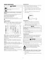
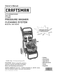
Operator's Manual
®
3000 PSi MAX
2.7 GPiVIMAX
_odei No. 580.752070
CUSTOMERHELPLINE
PRESSURE
WASHER
HOUriS: Non. - Fri. 8 a.m. to 5 p.m. (CT)
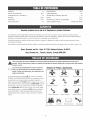
wAReeeG
Before using this product, read this
manual and follow atI Safety Rutes
and Operating Instructions.
®Safety
®AssembJy
ADVER'rENCmA®Operation
,, Maintenance
Antes de utiiizar el producto, Iea este
,, Parts
manuai y siga todas Ias Reglas de
Seguridad e Instrucciones de Uso.
,, Espa_oi, p. 34
Sears, Roebuck and Ca., Hoffman Estates, [L 68179 U.S.A.
Visit our Craftsman website: www.craftsman.eom
Part No. 203793GS Draft - (03/30/2007)
3
WARRANTY..........................................
SAFETYRULES......................................
2
2-5
FEATURES
ANDCONTROLS
..............................
ASSEMBLY
........................................
6
7-10
OPERATION
.......................................
SPECIFICATIONS
.....................................
11-15
16
MAINTENANCE
....................................
17-2!
STORAGE...........................................
22
TROUBLESHOOTH'_IG
..................................
23
REPLACEMENTPARTS..............................
24-31
EMISSION CONTROLWARRANTY .....................
32-33
ESPA__OL
.........................................
34-59
HOW TO ORDERPARTS ........................
BACKPAGE
If this pressure washer faiis due to a defect in materiai or workmanship within one year from the date of purchase, return it to
any Searsstore, other Craftsman outlet, or Sears Parts & Repair Center in the United States or Canadafor free repair (or
replacementif repair proves impossible).
Ali warranty coverage applies for only 90 days from date of purchase if this pressure washer is ever used for commercial or
rentai purposes.
This warranty gives you specific legal rights, and you may also have other rights which vary from state to state.
Sears, Roebuck and Ce,, Heffman Estates, JL 68179
Sears Canada Jnc,, Terente, 8ntarie,
Canada MSB 2B8
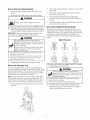
This is the safety alert symbol, tt is used to alert yea to potential persenaminjary hazards. Obey aH safety messages
that fellow this symbemto avoid pessiNe injury or death.
_Read
this pressurewasher.
manual carefully and
become
familiar
..... with your
Knew
its applications,
its limitations, and any hazards involved.
Hazard SymhoJsand Nteanings
The safety alert symboi (,_) is used with a signal word
(DAr/GER, CAUTIOr/,WARNING), a pictorial and/or a safety
messageto alert you to hazards. BANGERindicates a hazard
which, if not avoided, wi/'/resuIt in death or serious injury.
WARNINGindicates a hazard which, if not avoided, cou/d
result in death or serious injury. CAUTtONindicates a hazard
which, if not avoided, might result in minor or moderate
injury. NOTICEindicates a situation that could result in
equipment damage. Foiiow safety messages to avoid or
reduce the risk of injury or death.
Toxic Fumes
Hazardous Chemical
Electrical Shock
SlipperySurface
Fall
FluidInjection
Fire
Moving Parts
© Sears Brands, LLC
Explosion
Flying Objects
Operator'sManual
Kickback
Hot Surface
WARNING
_'_
Fuet and its vapors are extremely flammable and
explosive.
death.
Fire or explosion can cause severe burns or
Contents are harmful or fatai if swalIowed. Avoid
contact to eyes, skin or clothing. DO NOTtake
internaliy. Avoid breathing the mist or vapor.
Overexposureto eyes or skin can cause irritation.
Keep stabilizer out of the reach of chiidren.
Fuei stabiiizer is a hazardous chemical.**
Fresb StartTM fue! cap is designed to hold a cartridge whicb
contains fuel stabilizer.
• If SWALLOWED,call pbysician immediately. DO NOT induce
vomiting. If inhaled remove to fresh air. h_ case of eye or skin
contacL flusb with water for 15 rninutes.
• Store unopened cartridges in a cool, dry_well ventilated area.
Keep open cartridge in fuel cap, and fuel cap closed on fuel tank
when not in use.
WHEN ARRmNG OR BRAINING FUEL
o Turn pressure wasber OFFand let it cool at least 2 minutes
before removing fuel cap. Loosen cap slowly to relieve pressure
in tank.
o Fill or drain fuel tank outdoors.
• DO NOT over% tank. Allow space for fue! expansion.
o If fuel spills, wait until it evaporates before starting engine.
• Keep fuel away frorn sparks, open flames, pilot lights, heat, and
other ignition sources.
• DO NOT light a cigarette or smoke.
WHENSTARTINGEQUmPIVIENT
o Ensure spark plug, muffler, fuel cap, and air cleaner are in
place.
• h_the case of an emergency, contact a physician immediately
and call 1-800-424-9300 for material safety irfforrnation.
o DO NOTcrank engine with spark plug removed.
WHEN OPERATINGEQUIP_tENT
• *Fuel stabilizer contains: 2,6-di-tret-butylphenol (128-39-2) and aliphatic petroleum
distillate (64742-47-8),
• DO NOT tip engine or equiprnent at angle whicb causes fuel to
spill
WARNING
•
o
o
•
•
Running engine gives off carbon monoxide, an
odoriess, coloriess, poison gas.
Breathing carbon monoxide can cause headache,
fatigue, dizziness, vomiting, confusion, seizures,
nausea, fainting or death.
Some chemicals or detergents may be harmful if
inhaled or ingested, causing severe nausea,
fainting, or poisoning.
OperatepressurewasherONLYoutdoors.
Keepexhaustgasfrom enteringa confinedareathrough
windows,doors,ventilationintakes,or otheropenings.
DONOTstart or run engineindoorsor in an enclosedarea,
evenif windowsanddoorsare open.
Usea respiratoror maskwheneverthereis a cbancetbat
vapors rnaybe inhaled.
Readall instructionswith maskso you arecertaintbe rnaskwill
providethe necessaryprotectionagainstinhalingharmful
vapors.
o DO NOT spray' flamrnable liquids.
WHEN TRANSPORTmNG
OR REPAIRmNG
EQNIPI_IENT
o Transport/repair witb fuel tank EMPTYor with fuel shutoff valve
OFF.
o Disconnect spark plug wire.
WHEN STORINGFUEL OR EQUIPMENTWiTH FUEL mNTANK
• Store away from furnaces, stoves_water heaters_dotbes
dryers, or other appliances that have pilot light or other ignition
source becausetbey can ignite fuel vapors.
WARNING
Risk of electrocution.
Contact with power source can cause electric
shock or burn.
• NEVERspray' near power source.
WARNING
•
o
o
o
Starter cord kickback (rapid retraction) can result
in bodily injury. Kickback will pulI hand and arm
toward engine faster than you can Iet go.
Broken bones, fractures, bruises, or sprains
could result.
NEVERpull startercordwithout first relievingspraygun
pressure.
Whenstartingengine pull cord slowlyuntil resistanceis felt
andthen pul!rapidlyto avoidkickback.
After eachstartingatternptwhereenginefails to run,always
pointspraygun in safedirectionandsqueezespraygun trigger
to releasehigh pressure.Engagespraygutstrigger lock.
Firmlygraspspraygun with bothhandswhenusinghigh
pressuresprayto avoidiniury whenspraygun kicks back.
WARNING
pressure stream of water th_(ttlsJ_'_
equipment produces can cut through skin and its
_
,underlying tissues, ieading to serious injury and
_l
'_-
possible amputation.
Spray gun traps h gl water pressure, even when
engine is stopped and water is disconnected,
which can cause injury.
DO NOT allow CHILDRENto operate pressure washer.
NEVERrepair high pressure hose. Replaceit.
NEVERrepair leaking connections with sealant of any kind.
Replaceo-ring or seal.
NEVERconnect high pressure hoseto nozzle extension.
Keep high pressure hose connected to pump and spray gun
while system is pressurized.
ALWAYS point spray gun in safe direction and squeezespray
gun trigger to releasehigh pressure, every time you stop
engine. Engagetrigger lock when not in use.
NEVERaim spray guts at people, animals, or plants.
Use of pressure washer can create puddles and
slippery surfaces.
Kickback from spray gun can cause you to fail.
* Operatepressurewasherfrorn a stablesurface.
o Thecleaningareashouldhaveadequateslopesand drainageto
reducethe possibilityof a fall dueto slipperysurfaces.
o Be extremelycarefulif you rnustusethe pressurewasherfrom
a ladder,scaffolding,or anyothersimilarlocation.
o Firmlygraspspraygun with bothhandswhenusinghigh
pressuresprayto avoidinjury whenspraygutskicks back.
DO NOTsecure spray gun in open position.
DO NOT leave spray gun unattended while rnacbine is running.
NEVERuse a spray gun wlsich does not have a trigger lock or
trigger guard in place and in working order.
Always be certain spray gun, nozzbs and accessories are
correctly attached.
WARNING
Unintentional sparking can result in fire or
WARNING
'_¢
electrb shock.
Contact with muffler area can result in serious
burns.
WHENADJNSTmNG
ORMAKINGREPAIRS
TOYOURPRESSURE
WASHER
Exhaustheat/gases can ignite combustibles,
structures or damage fuel tank causing a fire.
o Disconnectthe sparkplug wire frornthe sparkplugand place
thewire whereit cannotcontactsparkplug.
WHENTESTmNG
FORENGINE
SPARK
* DONOTtouch hot partsandAVOIDhot exlsaustgases.
o Allowequipmentto cool beforetouching.
o Keepat least5 feet (152crn) of clearanceon all sidesof
pressurewasherincludingoverhead.
o Codeof FederalRegulation(CFR)Title 36 Parks,Forests,and
PublicPropertyrequireequipmentpoweredby an internal
combustionengineto havea sparkarrester rnaintainedin
effectiveworkingorder,complyingto USDAForestservice
standard5!00-16 or laterrevision.Inthe Stateof Californiaa
sparkarresteris requiredundersection4442 of the California
Publicresourcescode.Otherstatesrnayhavesimilar laws.
o Useapprovedsparkplug tester.
• DONOTcheckfor sparkwith sparkplug removed.
WARNING
Starter and other rotating parts can entangie
sands, hair, clothing, or accessories.
• NEVERoperate pressure washer without protective housing or
covers.
o DO NOTwear loose dothing_ iewelry or anything that may be
caught in the starter or other rotating parts.
o Tie up long hai! and rernove jewelry.
WARNING
jRisk of eye injury.
..L..__JSpray
can splash back or propel objects.
Always wear safety goggles when using this equipment or in
vicinity of where equipment is in use.
Before starting the pressure washer, be sure you are wearing
adequate safety goggles.
NEVERsubstitute safety'glasses for safety'goggles.
i
NOTICE
High pressure spray may damage fragiie items including
glass.
• DO NOT point spray gun at glass when using MAX (0°) nozzle.
NEVERaim spray gun at plants.
Improper treatment of pressure washer can damage it and
shorten its iife.
If you have questions about intended use, ask dealer or contact
Sears.
NEVERoperate units with broken or missing pa!ts, or without
protective housing or covers.
DO NOT by-pass any safety device on this rnachine.
DO NOT tamper with governed speed.
DO NOT operate pressure washer above rated pressure.
DO NOT modify pressure washer in any'way.
Before starting pressure washer in cold weather, check all parts
of the equiprnent to be sure ice has not formed there.
NEVERmove machine by pulling on hoses. Use handle
provided on unit.
Check fuel system for leaks or signs of deterioration, such as
chafed or spongy hose, !oose or missing clamps_or damaged
tank or cap. Correct all defects before operating pressure
washer.
This equipment is designed to be used with Sears authorized
parts ONLY. If equipment is used with parts that DO NOT
comply with minimum specifications, user assumes all risks
and liabilities.
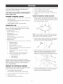
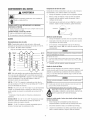
KNOWYOURPRESSUREWASHER
,r' F I_Read the Operator's Manual and safety rubs before operatingyour pressurewasher.
.... Compare the illustrations
withyour pressurewasher to familiarize
yourselfwiththe locations
ofvariouscontrolsand
adjustments. Save this manuaI for future reference,
Spray Gun
Nozzle Extension with
Quick Connect
ProjectPro@Nozzles
Cleaning Tank
HydroFoamTM Launcher
High Pressure Hose
Recoil Starter
Fuel Tank
Air Filter
Oil Fill Cap/Dipstick
Throttle Lever
& Choke Level
HigI1Pressure Outlet &
Water Inlet
Pump equipped with Automatic
Cool Down System
Air FHter -- Protects engine by filtering dust and debris out of
intake air.
Nezzb Exteesieewith Qabk Ceeeect -- Allows you to switch
between three different spray nozzles and HydroFoarnTM Launcher.
Autematb CeeJ Dawn System -- Cycles water through pump when
water reaches 125°-155°F. Warm water will discharge from purnp
onto ground. This system prevents internal pump damage.
OiJ FiJJCap!Dipstick -- Check and fill engine with oil here. See
page 19 for oil recommendations and filling instructions.
Cbaeieg Tack - Usedto provide HydroFoamTM wash or other
detergent to the low pressure water stream.
PrejectPre® Nezzles -- Max General, and Delicate Nozzles:for
various cleaning applications.
Pump -- Developshigh pressure.
Choke Lever -- Preparesa cold engine for starting.
ReceiJ Starter -- Usefor starting the engine manually.
FaemTack -- Fill tank with regular unleaded fuel. Always leave room
for fuel expansion.
Spray Qua -- Controls the application of water onto cleaning surface
with trigger device. Includes safety latch.
High Pressare Hese -- Connect one end to the water pump and the
other end to the spray gun.
Thrattle Lever--Sets engine in starting mode for recoil starter and
stops a running engine.
High Pressare Outbt -- To connect high pressure hose.
Water leJet-- Connect garden hose here.
HydreFeamTM kauecher -- Use to apply HydroFoamTM wash or
other detergents designed specifically for pressure washers.
Your cleaning system requires some assembIy and is ready
for use only after it has been properiy serviced with the
recommended oil and fuel.
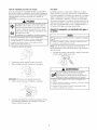
6.
7.
Connect pressure hose to spray gun and pump.
Connectwater supply to pump.
8.
Attach nozzleextension to spray gun.
Jf you have any prohmems
with the assembly of your
pressurewasher, please call the pressurewasher hempline
at 1o800o222o3136.
9.
Select/attach quick connect ProjectPro@nozzle to nozzle
extension.
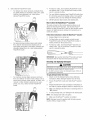
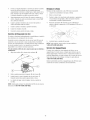
Attach Handle and Aecesse_ Tray
UNPACKTHE PRESSUREWASHER
1.
1.
Remove everything from carton except pressure washer.
2.
Open carton completely by cutting each corner from top
to bottom.
3.
Remove pressure washer from carton.
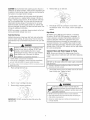
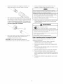
Placehandle (A) onto handle supports (B) connected to
main unit. Make sure holes (C) in handle align with holes
(C) on handle supports.
CARTONCONTENTS
Checkali contents, if any parts are missing or damaged, call
the pressure washer hetpline at 1=800=222=3136.
° Main Unit
*
Handlewith 6ieaning Tank Assembly
o Accessory Tray
°
*
High Pressure Hose
Spray Gun
o
NozzleExtensionwith Quick Connect Fitting
,
°
HydroFoamTM Wash
Oil Bottle
o
Parts Bag (which includes the following):
NOTE:It may be necessary to move the handle supports
from side to side in order to align the handie so it wiii slide
over the handie supports.
2. Insert carriage boits (A) through holes from outside of
unit and attach a plastic knob (B) from inside of unit.
Tighten by hand.
o
Operator's Manual
,
Owner's Registration Card
,
Safety Goggies
,
DetergentSiphoning Hose/Filter
,
Bagcontaining 3 multi-coiored ProjectPro@Nozzles
°
HydroFoamTM Launcher
o
HydroFoamTM Launcher & Wash Instruction Sheet
°
FreshStart Fuel Cartridge
*
HandleFasteningHardwareKit (which includes):
°
Carriage Bolts (2)
°
Plastic Knobs (2)
°
Tree Clips (4)
Becomefamiiiar with each piece before assembling the
pressure washer. Identify ali contents with the iiiustration on
page 6. if any parts are missing or damaged, call the
pressure washer helpline at 1=888=222=3136.
3.
Piaceaccessory tray (A) over hobs (C) on handle
(viewing from front of unit). Push the tree clips (B) into
the holes untii they sit fiat against the accessory tray.
/
/
ASSEMBLINGCLEANINGSYSTEM
Your
Craftsman
cJeaning system
wJJJ need assembJy
operation:
1.
Fiii out and send in registration card.
2.
3.
Attach handle and accessory tray.
Connect detergent siphon hose to pump.
4.
5.
Add oii to engine crankcase.
Add fuel to fuel tank.
before
Insert multi-colored ProjectPro@nozzlesand other
supplied accessories in spaces provided in accessory
tray. See How to Use Accessory Tray.
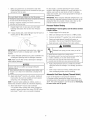
Attach Detergent Siphon Hose te Pemp
Add Fuel
The pressure washer is equipped with two detergent
siphoning hoses. One is attached to the cleaning tank and
one is loose for siphoning pressure washer safe detergents
from a bottle or container.
Fuel must meet these requirements:
o Clean,fresh, unleaded gasoline.
. A minimum of 87 octane/87 AKI (91 RON). High altitude
use, see High Altitude.
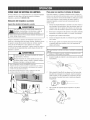
Attach one of the detergent siphon hoses (A) to the barbed
hose fitting (B) on the pump,
. Gasolinewith up to 10% ethanol (gasohot) or up to
15% MTBE (methyl tertiary butyl ether) is acceptable.
Avoid pressure washer damage.
Failureto follow Operator's Manual for fuel
recommendations voids warrant,G
DONOTuseunapprovedgasolinesuchas E85.
DONOTmix oil in gasoline.
DONOTmodifyengineto run on alternatefuels.
IMPORTANT:Only one detergent siphoning hose can be used
at a time. When cleaning tank is not used, make sure
detergent shut-off valve on cleaning tank is in the "Off"
position.
Add Engine Oit
1.
Place pressure washer on a flat, Ievei surface.
2.
Cleanarea around oii fiii and remove yeiiow oii fiii
cap/dipstick.
To protect the fuei system from gum formation, mix in a fuel
stabiiizer when adding fuel. See Storage. Ali fuet is not the
same. if you experience starting or performance problems
after using fuel, switch to a different fuei provider or change
brands. This engine is certified to operate on gasoline. The
emission control system for this engine is EM (Engine
Modifications).
WARNING
Fuetand its vapors are extremely flammable and
explosive.
NOTE:See 0i/Recommendations in Maintenancesection.
Verify provided oil bottle is the correct viscosity for current
ambient temperature.
3.
Using oiI funnel (optional), slowly pour contents of
provided oil bottie into oil fill opening.
improper treatment of pressure washer can damage it and
shorten its iife.
DONOTattemptto crankor startthe enginebeforeit hasbeen
properlyservicedwith the recommended
oil. This may resultin
an enginefailure.
4.
Replace oil fill cap/dipstick and fully tighten.
death.
Fire or explosion can cause severe burns or
WHENADDmNGFUEL
o TurnpressurewasherOFFand let it coo[at least2 minutes
beforeremovingfuelcap. Loosencapslowlyto relievepressure
in tank.
o Fillfuel tankoutdoors.
• DONOTover%tank.Allowspacefor fue! expansion.
o If fuel spills wait until it evaporatesbeforestartingengine.
• Keepfuelawayfrom sparks,openflames,pilot lights,heat,and
otherignitionsources.
o
DONOTlight a cigaretteor smoke.
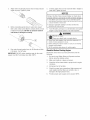
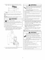
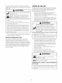
1,
Cleanarea around fuet filI cap, remove cap.
2,
Slowly add regular unleaded fuet (A) to fuel tank (B). Be
carefui not to overfiii. Aliow about 1.5" (4 cm) (C) of tank
space for fuel expansion.
CAUTJSN!AtcohoI-blended fuels (caiied gasohoi, ethanol or
methanoi) can attract moisture, which ieads to separation and
formation of acids during storage. Acidic gas can damagethe
fuei system of an engine whiie in storage.
To avoid engine problems,the fueI system should be treated
with a fuet preserver or emptied beforestorage of 30 days or
longer, if adding a fue! preserver, fiii the fue! tank with fresh
fuei. if only partialiy filied, air in the tank wiii promote fuel
deterioration during storage, if fueI preserver is not used,
drain the fueI tank, start the engineand iet it run untii the fuel
lines and carburetor are empty. Use fresh fueI next season.See
Storagefor additionai information.
NEVERuse engine or carburetor cleaner products in the fuel
tank as permanent damage may occur.
FreshStart FuelCap
Adding fuel preserver helps keepfueI fresh and carburetors
clean for easier starting, ali season iong. This new fuei cap
automatically drips concentrated fuel preserver into your fuel
tank.
BANGER
Contents are harmful or fatal if swallowed. Avoid
contact to eyes, skin or clothing. DONOTtake
internally. Avoid breathing the mist or vapor.
Overexposureto eyes or skin can cause irritation.
Keep stabilizer out of the reach of shiidren.
Fuei stabiiizer is a hazardous chemical.**
If SWALLOWED,
callphysicianimmediately.
* h_the caseof an emergency,contacta physicianimmediately
and call1-800-424-9300for materialsafety[nforrnation.
**Fuel stabilizer contains: 2,6-dbtret-butylphenol (128-39-2) and aiiphatic petroleum
distillate (64742-47-8),
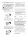
1.
Placecartridge into fuet cap.
4.
Reinstall fue! cap on fuel tank.
5.
Periodicaliy check the cartridge to ensure there is stiii
fuei stabilizer inside. If it is empty, remove cartridge and
replace.
Nigh ,_Nitude
At altitudes over 5,000 feet (1524 meters), a minimum
85 octane / 85 AKI (89 RON)gasoline is acceptable. To
remain emissions compiiant, high aititude adjustment is
required. Operationwithout this adjustment wiii cause
decreasedperformance, increased fueI consumption, and
increased emissions. See a qualified Sears dealer for high
altitude adjustment information. Operation of the engine at
altitudes below 2,500 feet (762 meters) with the high altitude
kit is not recommended.
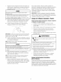
Cennect Hese and Water Supply te Pump
NOTE:Removeand discard the shipping caps from the
pump's high pressure outlet and water inlet before attaching
hoses.
DO NOT run the pump without the water supply connected
and turned on.
Damageto equipmentresultingfrom failureto followthis
instructionwill void warranty
Uncoil high pressure hose and attach one end of hose to
base of spray gun. Tighten by hand.
....
j
j/
/
2.
Pushto "snap" cartridge into piace.
3.
Removetab to expose membrane.
WARNING
The high pressure stream of water that this
_
iMPORTANT: DO NOT remove the silver foil seal on the
opposite side.
underlying
quipment tissues,
producesieading
can cuttothrough
serious skin
injury
and
and
its
}ossibb amputation.
o NEVERconnecthigh pressurehoseto nozzleextension.
• Keephigh pressurehoseconnectedto purnpand spraygun
whilesystemis pressurized.
• Alwaysbe certainspraygun,nozzbsand accessoriesare
correctlyattached.
.
Attach other end of high pressure hose to high pressure
outlet on pump. Tighten by hand.
5.
Connectgarden hose (not to exceed 50 feet in length) to
water inlet. Tighten by hand.
NOTICE
Using a One Way Valve (vacuum breaker or check valve)
at pump inlet can cause pump or inlet connector damage.
ThereMUSTbeat leastten feet (3 rn) of unrestrictedgarden
hosebetweenthe pressurewasherinletandany'device,suchas
a vacuumbreakeror checkvalve.
3.
Damageto equipmentresultingfrom failureto follow this
instructionwill voidwarranty,
Before connecting garden hose to water inlet, inspect
inlet screen. Cleanscreen (A) if it contains debris or have
it replacedif damaged. DO NOTrun pressure washer if
inlet screen is damaged or missing.
6, Turn ONwater, point gun in a safe direction and squeeze
trigger to purge pump system of air and impurities.
WARNING
IRisk of eye injury.
_Spray
can splash back or propel objects.
Alwayswearsafetygoggleswhen usingthis equipmentor in
vicinityof whereequipmentis in use.
Beforestartingthe pressurewasher,be sureyouare wearing
adequatesafetygoggles.
NEVERsubstitutesafetyglassesfor safetygoggles.
.
Run water through garden hose for 30 seconds to flush
it of debris. Turn off water.
Checklist Befere Starting Engine
Reviewthe unit to ensure you have performed all of the
following:
IMPORTANT:DO NOTsiphon standing water for the water
supply. Use ONLY cold water (less than 100%).
10
1.
Be sure to read Safety Ru/'esand Operationsections
before using the cleaning system.
2.
Make sure handle is in place and secure.
3.
Checkthat oii has been added to proper level in engine
crankcase.
4.
Add proper fuel to fuei tank.
5.
Checkfor proper hose connections (high pressure and
water suppiy) and that there are no kinks, cuts, or
damageto the higil pressure hose.
6.
Provide proper water supply (not to exceed IO0°F).
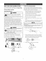
HOWTO USEYOUR CLEANINGSYSTEM
To Start Your Cleaning System
If you haveany probbms operating your pressure washer,
please call the pressure washer heJpfineat 1-800-222-3136,
To start your engine=poweredcleaning system for the first
time, foiiow these instructions step=by=step.This information
also applies whenever you start the engine after you have let
the pressure washer sit idle for at bast a day.
Pressure Washer Lecation
PressureWasherCJearance
1.
Placepressure washer near an outside water source
capable of supplying water at a flow rate greater than
3.7 galions per minute and no iess than 20 PSi at
pressure washer end of garden hose.
2.
Checkthat higil pressure hose is tightty connected to
spray gun and pump. See Assemby for illustrations.
3.
Make sure unit is in a ievei position.
4.
Connectgarden hose to water intet on pressure washer
pump.
5.
Turn ONwater, point gun in a safe direction and squeeze
trigger to purge pump system of air and impurities.
VANNING
Exhaustheat/gases can ignite combustibbs,
structures or damage fuei tank causing a fire.
o Keepat least5 ft. (152 cm) clearanceon all sidesof pressure
washerincludingoverhead.
Mace pressure washer outdoors in an area that wiii not
accumulate deadty exhaust gas. DO NOT piace pressure
washer where exhaust gas (A) could accumulate and enter
inside or be drawn into a potentiaily occupied building.
Ensureexhaust gas is kept away from any windows, doors,
ventiiation intakes, or other openings that can aliow exhaust
gas to coiiect in a confined area. Prevaiiingwinds and air
currents should be taken into consideration when positioning
_ressurewasher.
[
DO NOT run the pump without the water supply connected
and turned on.
t
WARNING
6.
Running engine gives off carbon monoxide, an
odorless, colorless, poison gas.
Breathingcarbon monoxide can cause headache,
fatigue, dizziness, vomiting, confusion, seizures,
nausea, fainting or death.
° OperatepressurewasherONLYoutdoors.
o Keepexhaustgasfrom enteringa confinedareathrough
windows,doors,ventilationintakes,or otheropenings.
• DONOTstat or run engineindoorsor in an enclosedarea,
evenif windowsanddoorsare open.
instructionwill
amageto equipment
void warranty
resultingfrom failureto followthis
Attach nozzleextension to spray gun. Tighten by hand.
X
Choose ProjectPro@nozzle you want to use, puiI back
on coiiar of nozzle extension, insert nozzle and release
coliar. Tug on nozzle to make sure it is securely in place.
See How to Use ProjectPro@Nozzle System.
8.
11
Engagetrigger lock (A) to spray gun trigger.
9.
Move throttie lever (A) to "Fast" position, shown here as
a rabbit.
12. Return recoii starter siowiy. DO riOT let rope "snap
back" against starter.
13. When engine starts, siowiy move choke iever to "Run"
position, as engine warms, if engine falters, move choke
lever to "Choke" position, then to "Run" position.
14. After each starting attempt, where engine fails to run,
always point gun in safe direction and squeeze spray
gun trigger to releasehigh pressure. Move choke lever
to "Choke" position, and repeat steps 11 through 13.
10= Move choke lever (B) to "Choke" position.
NOTE:For a warm engine, be sure the choke lever is in the
"Run" position.
15. If engine faiis to start after six pulis, move choke iever to
"Run" position, and repeatsteps 11 through 13.
iMPORTANT: Before starting the pressure washer, be sure
'ou are wearing adequatesafety goggles.
NOTE:Always keepthe throttle iever in the "Fast" position
when operating the pressure washer.
WABNING
WARNING
The high pressure stream of water that this
equipment produces can cut through skin and its
underlying tissues, ieading to serious injupj and
_ossible amputation.
Spray gun traps high water pressure, even when
engine is stopped and water is disconnected,
which can cause injury.
Risk of eye injury.
=_Spray
can sp ash back or propel objects.
Alwayswearsafetygoggleswhenusingthis equiprnentor in
vicinity of whereequipmentis in use.
Beforestartingthe pressurewasher,besureyou arewearing
adequatesafetygoggles.
NEVERsubstitutesafetyglassesfor safetygoggles.
o DONOTa!lowCHILDREN
to operatepressurewasher.
• Keephigh pressurehoseconnectedto pumpand spraygun
whilesystemis pressurized.
o NEVERaim spraygun at people,animals_or plants.
• DONOTsecurespraygun in openposition.
o DONOTleavespraygun unattendedwhilemachineis running.
o NEVERusea spraygun whichdoesnot havea triggerlock or
triggerguardin placeandin workingorder.
o Alwaysbe certainspraygun,nozzlesand accessoriesare
correctlyattached.
1. When starting engine, position yourself as
recommended, grasp handle and pull recoii starter
lightly until you feel some resistance, then pulI briskly.
WARNING
Contact with muffler area can result in serious
burns.
Exhaustheat/gases can ignite combustibles,
structures or damage fuel tank causing a fire.
WARNING
Starter cord kickback (rapid retraction) can result
in bodily injury. Kickback wilI pulI hand and arm
toward engine faster than you can iet go.
Broken bones, fractures, bruises, or sprains
could result.
o
DO NOTtouch hot parts and AVOID hot exhaust gases.
®
Allow equipment to cool before touching.
o
Keep at least 5 feet (152 cm) of clearance on all sides of
pressure washer including overhead.
Code of Federal Regulation (CFR)Title 36 Parks Forests, and
Public Property require equiprnent powered by an internal
combustion engine 1o have a spark arrestor rnaintained in
effective working order, complying to USDAForest service
standard 5100-1C or later revision. In tl_e State of California a
spark arrestor is required under section 4442 of the California
Public resources code. Other states may have similar laws.
o NEVERpull startercordwithout first relievingspraygun
pressure.
• Whenstartingengine_pull cord slowlyuntil resistanceis felt
andthen pul!rapidlyto avoidkickback.
o After eachstartingattempt whereenginefails 1orun,always
pointspraygun in safedirectionandsqueezespraygun trigger
to releasehigh pressure.Engagesprayguntrigger lock.
o Firmlygraspspraygun with bothhandswhenusinghigh
pressuresprayto avoidinjury whenspraygun kicks back.
12
How to Stop Your CJeaningSystem
.
1= Reieasespray gun trigger and let engine idte for two
minutes.
2.
Move throttie to SLOW position, then STOPposition.
3.
Insert multi-coIored ProjectPro@nozzles in spaces
provided in accessory tray.
4.
Insert HydroFoamTM iauncher in space provided in
accessory tray next to the multi-colored ProjectPro@
nozzles.
WARNING
.
,,_
Backfire, fire or engine damagecouId occur.
o DONOTstope%ine bymovingchokeleverto "Cheke"position.
3.
Mace spray gun through hole on accessory tray on right
side of unit.
Hang high pressure hose oil hook attachedto accessory
tray oll front of tray as shown.
Hew ts Use PrsjectPrs@ Hszz!e System
The quick-connect on the nozzle extension atiows you to
switch between three different ProjectPro@system nozzles.
ProjectPro@nozzles can be changed while pressure washer
is running once spray gun trigger lock is engaged. The
ProjectPro® nozzles vary the pressure and spray pattern as
shown.
ALWAYSpoint spray gun in a safe direction and squeeze
spray gun trigger to releaseretained high water pressure.
Jt_PORTANT:Spray gun traps high water pressure, even
when engine is stopped and water is disconnected.
WANNING
High Pressure
The high pressure stream of water that this
equipment produces can cut through skin and its
_
)ossibieamputation.
nderlying tissues, ieading to serious injury and
Spray gun traps high water pressure, even when
engine is stopped and water is disconnected,
which can cause injury.
, Keephigh pressurehoseconnectedto purnpand spraygun
whilesystemis pressurized.
o ALWAYSpointspraygun in safedirectionand squeezespray
gun trigger,to releasehigh pressure everytime you stop
engine.Engagetrigger lockwhennot in use.
4.
Delicate
40° Yellow
2350 PSI
2.7 GPM
Engagetrigger iock on spray gun when not in use.
Max
0° Red
3000 PSi
2.3 GPM
Fellew these iestructiees te changePrejectPre@ nezzles:
1. Engagetrigger lock on spray gun.
Hew ts Use Accesssry Tray
The unit is equipped with an accessory tray with piaces to
store your ProjectPro@nozzles, HydroFoamTM iauncher, spray
gun and nozzleextension. There is aiso a hook at the front of
the accessory tray to hold your high pressure hose. Identify
ali accessories with the iiiustration on page 6.
WARNING
The high pressure stream of water that this
underlying
serious skin
injup/and
quipment tissues,
producesieading
can cuttothrough
and its
}ossible amputation.
o NEVERexchangeProjectPro®nozzleswithoutlockingthe
triggerlock on the spraygun.
• DONOTtwist ProjectPro®nozzleswhilespraying.
_
NOTE:The extra hoie in the tray is for storing a utiiity brush.
The extra clip in the tray is for storing a turbo nozzle.The
brush and turbo nozzle are NOT included with your pressure
washer. You can buy these items as optional accessories.
1.
General
15° Orange
2675 PSI
2.5 GPM
Place nozzle extension through hole on accessory tray,
as shown.
2.
13
PuIi back coiiar on quick-connect and puli current
ProjectPro@nozzle off. Store ProjectPro@nozzlesin
holder provided oll the accessory tray.
,
Select desired ProjectPro® nozzle:
*
Fordelicate rinse (lower pressure and higher flow),
for gentb cleaning of cars/trucks, boats, RV's, patio
furniture, lawn equipment, etc. select yellow
delicate ProjectPro® nozzle.
4.
Pull back on collar, insert selected ProjectPro@ nozzle
and releasecollar. Tug on ProjectPro@nozzle to make
sure it is secureiy in ptace.
5.
For most effectivecleaning, keep ProjectPro@nozzlefrom
8 to 24 inches away from cleaningsurface. If you get the
nozzietoo ctose, you may damagethe cleaningsurface.
6.
DONOTget closerthan 6 incheswhen cleaningtires.
Hew te Use the HydroFoam TM Launcher
The quick-connect on the nozzleextension aliows you to
attach the HydroFoamTM launcher. Usethe HydroFoamTM
launcher to appiy HydroFoamTM wash or other project specific
cleaners to heip break down stubborn dirt and grime on a
variety of surfaces.
Fellowthese instru_,-tians
ta attach the HydrePeam
TM launcher:
Forgeneralrinsing (medium pressureand medium
flow), idealfor most atI purposecleaningsuch as
home siding, brick patios,wood decks, drivewaysand
sidewalks,garagefloors, etc., selectorangegeneral
ProjectPro@nozzle.
1.
Engagetrigger iock oil spray gun.
2.
Puli back coliar on quick-connect and puli current
ProjectPro@nozzle off. Store ProjectPro@nozzles in
holder provided on the accessory tray.
3.
Puii back on coiiar, insert HyrdoFoamTM iauncher and
releasecollar. Tug on HyrdoFoamTM launcher to make
sure it is securely in place.
IMPORTANT:Also see the HydroFoamTM launcher and wash
instruction sheet for important instructions and uses.
Cteanin9 and Applyin9 Detergent
injury, and/or property damage.
NEVERusecausticliquidwith pressurewasher.
UseONLYpressurewashersafedetergents/soaps.
Followall
rnanufacturersinstructions.
l"e apply detergent fallow these steps:
1. Attach one of the detergent siphon hoses following
instructions Attach Oetergent Siphon Hose to Pump.
For maximum rinsing (higher pressure and lower
flow), for stubborn or hard to reach surface such as
second story surfaces, paint removal, oii stains, rust
removal or other stubborn substances (tar, gum,
grease, wax, etc.), select red max ProjectPro@
nozzle.
2.
Review ProjectPro® nozzle and HydroFoamTM launcher
use.
3.
PrepareHydroFoamTM wash according to instructions on
the bottle or prepare detergent soiution as required by job.
4.
Make sure detergent shut-off valve on cleaning tank is in
"Off" position.
5.
If using cleaning tank, pour detergent into cleaning tank.
NOTE:The cleaning tank holds one galIon.
6.
Make sure HyrdoFoamTM Launcher is instaibd.
NOTE:Detergentcannot be applied with the high pressure
nozzles (Yellow, Orange or Red).
14
7. Makesuregarden
hoseis connected
towaterinlet.
Check
thathighpressure
hoseisconnected
tospraygun
andpump.Turnonwater.
You must attach alI hoses before
Starti_gthe enginewithoutall the hosesconnectedandwithout
the waterturnedONwill damagethe pump.
Darnageto eqdpmentresultingfrom failureto follow this
instructionwill void warranty.
8.
For best resuits, scrub the HydroFoamTM wash covered
surface to heip remove stubborn dirt, grime and stains. For
vehicles, use a soft car wash brush or mitt. For decking,
siding and concrete, use a brush appropriate for the type of
surface being cleaned.
IMPORTANT:When using the detergent siphoning hose, you
must flush the detergent siphoning system after ea@ use by
placing the fiiter into a bucket of clean water, then run the
pressure washer in low pressure for 1-2 minutes.
Pressure Washer Rinsing
Engagetrigger iock on spray gun and start engine
foiiowing instructions How to Start Your Pressure
Washer.
AfterNydroFoamTM wash is applied, s¢onrthe surfane and rinse
it deae as fdbwn:
9£ If using cteaning tank, rotate detergent shut-off valve on
cleaning tank to "On" position (A).
1.
Engagetrigger lock on spray gun.
2.
Make sure detergent shut=off vaive is in "Off" position.
3.
Remove HyrdoFoamTM Launcherfrom nozzteextension.
4.
Seiect and instaii desired ProjectPro@nozzle,as
described in How to Use ProjectPm@ NozzleSystem.
5.
Keepspray gun a safe distance from spray surface.
WARNING
/
f
IMPORTANT:If using detergent siphoning hose, make sure
detergent shut-off valve ell cleaning tank is in the "Off"
position.
Kickback from spray gun can cause you to fail.
* Operatepressurewasherfrom a stablesurface.
, Beextremelycarefulif you mustusethe pressurewasherfrom
a ladder,scaffolding,or anyothersimilarlocation.
o Firmlygraspspraygun with both handswhenusing high
pressuresprayto avoidinpry whenspraygun kicks back.
9B. If using detergent siphoning hose, placesmall filter end
of detergent siphoning tube into detergent container.
NOTE:Make sure the filter is fully submerged in detergent
while applying detergent.
6.
NOTICE
Contact with the hot muffler can damage detergent
siphoning tube.
Wheninsqting the filter into a detergentsolutionbottle,route
the tubeso asto keepit from inadvertently'
contactingthe hot
rnuffler.
Apply a high pressure spray to a small area and then
check the surface for damage. If no damage, proceed to
step 7.
Start at top of area to be rinsed, working down with
same overlapping strokes used for cleaning.
Autemati¢ Cod Dewu System (Thermal Relief}
10. Appiy HydroFoamTM wash to a dry surface, starting at
lower portion of area to be washed and work upward,
using iong, even, overlapping strokes.
If you run the engine on your pressure washer for
3-5 minutes without pressing the trigger on the spray gun,
circulating water in the pump can reach temperatures above
125°F. The system engagesto cool the pump by discharging
the warm water onto the grennd.
NOTE:To prevent water spotting on vehicles, work in a
shaded area and allow surfaces to coot before beginning.
11. Allow HydroFoamTM wash to soak in between
3-5 minutes before washing and rinsing. Reappiy as
needed to prevent surface from drying. DO NOTailow
HydroFoamTM wash to dry on (prevents streaking).
15
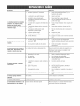
ENGINETECHNICALiNFORtViATION
PRODUCT
SPECiFiCATiONS
This is a single cylinder, overhead valve (OHV), air cooled
engine, it is a iow emissions engine.
PressureWasherSpecifications
In the State of Caiifornia, Model 120000 engines are certified
by the California Air Resources Board to meet emissions
standards for 125 hours. Such certification does not grant
the purchaser, owner or operator of this engine any
additional warranties with respectto the performance or
operational life of this engine. The engine is warranted soidy
according to the product and emissions warranties stated
elsewhere in this manual=
Water Supply Temperature ..........
Shipping Weiglst.............................
Max Outbt Pressure .......................
Max Ftow Rate .............................
Chemicat Mix.........................
3,000 PSi
2.7 GPM
Use as directed
Not to exceed IO0°F
71 Ibs.
Engine Specifications
Bore .................................
£69 in. (68mm)
Stroke ...............................
£04 in. (52ram)
Displacement ........................
11.57 in. (190 cc)
SparkPlug
Type: .....................
Briggs & Stratton 491055S
SetGap To: ......................
O.020inch(O.50mm)
ArrnatureAir Gap: ...........
0.006-0.014 in.(O.15-0.36rnm)
Valveclearancewith valvespringsinstalledand piston1/4in,
(6 turn)pasttop deadcenter(checkwhenengineis cold),
Intake ....................
0.004°0.006in.(0.10=0.15ram)
Exhaust ..................
0.004-0.008 in.(O.10-O.20turn)
FuelCapacity...............................
1.6 Quarts
Oil Capacity .......................
22 Ounces(0.65 liter)
Power Ratings
The gross power rating for individuaI gas engine models is
labeled in accordance with SAE (Society of Automotive
Engineers)code J1940 (Small Engine Power & Torque
Rating Procedure), and rating performance has been
obtained and corrected in accordancewith SAEJ1995
(Revision 2002=05). Torque values are derived at 3060 RPM;
horsepower values are derived at 3600 RPM. Actuai gross
engine power wiii be lower and is affected by, among other
things, ambient operating conditions and engine-to-engine
variabiiity. Given both the wide array of products on which
engines are placed and the variety of environmental issues
appiicabb to operating the equipment, the gas engine wiii not
develop the rated gross power when used in a given piece of
power equipment (actual "on-site" or net power). This
difference is due to a variety of factors including, but not
limited to, accessories (air cteaner, exhaust, charging,
cooiing, carburetor, fuel pump, etc.), appiication iimitations,
ambient operating conditions (temperature, humidity,
altitude), and engine-to-engine variabiiity. Due to
manufacturing and capacity iimitations, Briggs & Stratton
may substitute an engine of higher rated power for this
Series engine.
NOTE:For practicai operation, the engine ioad should not
exceed 85% of rated power. Engine power will decrease
3-I/2% for each 1,000 feet (300 meters) above sea Ievei and
1% for each 10° F (5.6° C) above 77° F (25° C). It should
operatesatisfactorily at an angle up to 15°.
16
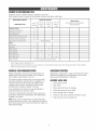
OWNER'SRESPONSiBiLiTIES
Follow the hourly or calendar intervals, whichever occurs first.
More frequent service is required when operating in adverse conditions noted below.
MABNTENANCE
SCHEBULE
OPERATINGINTERVALS
SERVICEDATES
_ABNTENANCETASK
Before
Each Use
Hours or
Every 25
Yearly
1
Hours or
Evely 50
Yearly
Every 1O0
Hours or
FILL IN DATESAS YOU COMPLETE
REGULARSERVICE
Yearly
PRESSURE WASHER
X1
Chec_dcieanwater inlet screen
Check high pressure hose
X
Check detergent hose
X
Check spray gun and assembly for leaks
X
Purge pump of air and contaminants
X
Prepare pump for storage below 32°F
ENGINE
Check oil level
Clean debris
See WiRter Storage,
×
×
Change engine oil
X_
Service air cleaner
X
Service spark plug
×
Service spark attester
X_
Clean cooling system
Prepare for storage
if unit is to remain idle for longer than 30 days,
Clean if clogged. Replace if perforated or torn.
Change oil after the first (5) operating hours and every 50 hours or yearly thereafter. Changesooner when operating under dirty or dusty conditions.
Replace more often under dirty or dusty conditions,
GENERALRECOMMENDATIONS
EMISSIONCONTROL
Reguiar maintenancewill improve the performance and
extend the life of the pressure washer. Seeany Sears or
other qualified service deaier for service.
Maintenance, replacement or repair of the emission control
devicesand systems may be performed by any non-road
engine repair establishment or individual.
The pressure washer warranty does not cover items that
have been subjected to operator abuse or negligence. To
receivefuli value from the warranty, the operator must
maintain pressure washer as instructed in this manual
including proper storage as detaiied in Storage.
BEFOREEACHUSE
Some adjustments wili need to be made periodicaliy to
properly maintain your pressure washer.
Ali service and adjustments should be made at ieast once
each season. Foliow the requirements in the "Maintenance
Schedule" chart above.
NOTE:Oncea year you should clean or replace the spark
ptug and replace the air fiiter. A new spark piug and clean air
fiiter assure proper fuel-air mixture and hetp your engine run
better and last longer.
17
1.
Checkengine oil Ievei.
2.
Cleandebris.
3.
Checkwater inlet screen for damage.
4.
Checkhigh pressure hose for ieaks.
5.
Checkcleaning tank for damage.
6.
Checkgun and nozzteextension assembly for leaks.
7.
Purge pump of air and contaminants.
PRESSURE
WASHERMAINTENANCE
Hezzle Maintenance
A pulsing sensation felt while squeezing the spray gun trigger
may be caused by excessivepump pressure. The principal
cause of excessive pump pressure is a nozzleclogged or
restricted with foreign materiais, such as dirt, etc. To correct
the problem, immediately clean the nozzle following these
instructions:
CmeanDebris
Daily or before use, clean accumuiated debris from cleaning
system. Keep iinkage, spring and controis clean. Keep area
around and behind muffler free from any combustibie debris.
Inspect cooiing air siots and openings on the pressure
washer. These openings must be kept clean and
unobstructed.
Cieaning system parts should be kept clean to reducethe risk
of overheating and ignition of accumuiated debris.
.
1.
Shut off engine and turn off water supply.
2.
Remove nozzlefrom end of nozzle extension.
3= Use a small paper clip to free any foreign material
clogging or restricting nozzle (A).
Use a damp cloth to wipe exterior surfaces clean.
NOTICE
j Improper treatment of pressure washer can damage it and
_ts
_horten
_
....
L: DONOTinsert anyobjectsthroughcoolingslots.
,
Use a soft bristle brush to ioosen caked on dirt, oii, etc.
,
Usea vacuumcleanerto pick up loose dirt and debris.
4= Using a garden hose, remove additionai debris by back
flushing water througil nozzteextension. Back flush
between 30 to 60 seconds.
Check and Cmean[n_et Screen
Examine garden hose inlet screen. Clean if it is clogged or
replace if it is torn.
Check High Pressnre Hese
High pressure hoses can develop ieaks from wear, kinking,
or abuse, inspect hose before each use. Checkfor cuts,
leaks, abrasions, bulging of cover, or damage or movement
of couplings. If any of ttlese conditions exist, replace hose
immediately.
WARNING
l
Reinstaiinozzleinto nozzleextension.
6.
Reconnect nozzle extension to spray gun.
7.
Reconnect water supply, turn on water, and start engine.
8.
Test pressure washer by operating with each quick
connect nozzle.
O_Ring Maintenance
Purchasean O-Ring RepairKit at your iocai Searsor by caliing
1-See-4-MY-HOME(469-4663) or online at www.sears.com, it
is not includedwith the pressurewasher.This kit includes
replacemento-rings, rubber washerand water inletfilter=Referto
the instructionsheet providedin the kit to serviceyour unit's
o-rings.
pressure stream
)ossible
5.
mtation.
NEVERrepairhigh pressurehose.Replaceit.
ReplacementhoseratingMUSTexceedmaximumpressure
ratingof unit.
WARNING
The high pressure stream of water that this
Check Gnn and Hezzle Extensien
Examine hose connection to spray gun and make sure it is
secure. Test trigger by pressing it and making sure it springs
back into piace when you releaseit. Put safety iatch in UP
position and test trigger. You should not be able to press
trigger. Replacespray gun immediately if it fails any of these
tests.
_
underlying
serious skin
injury
and
quipment tissues,
producesieading
can cuttothrough
and
its
)ossible amputation.
o NEVERrepairleakingconnectionswith sealantof anykind.
Replaceo-ring or seal.
Primp OiJ Maintenance
DO NOTattempt any oil maintenance on this pump. This
model does not require any pump oil maintenance. The pump
is pre-iubricated and seaiedfrom the factory, requiring no
additional lubrication for the life of the pump.
18
ENGINEMAINTENANCE
CheckingOil Level
OiI level should be checked prior to each use or at least every
5 hours of operation. Keep oii ievei maintained.
1. Make sure pressure washer is on a ievei surface.
WARNING
Unintentional sparking can result in fire or
_
electric shock.
2.
Remove oii dipstick and wipe dipstick with clean cioth.
Reptaceand tigilten dipstick. Removeand and check oil
levei.
3.
Verify oiI is at "FuIF' mark on dipstick. Replace and
tighten dipstick.
1.
Make sure pressure washer is on a Ievei surface.
2.
Checkoii ievei as described in Checking Off Level
3.
If needed,siowiy pour oil into oil fiii opening to the
"Full" mark on dipstick. DO NOT overfill.
WHENADJUSTmNGOR MAKmNGREPNRSTO YOUR PRESSURE
WASHER
* Disconnect the spark plug wire from the spark plug and place
the wire where it cannot contact spark plug.
WHENTESTINGFOR ENGmNE
SPARK
* Use approved spark plug tester.
o DO NOTcheckfor spark with spark plug rernoved.
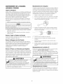
Oil
oimRecommendations
NOTE:Use a high quality detergent oiI ciassified "For Service
SF, SG, SH, SJ" or higher. DO NOT use special additives.
1.
Choose a viscosity according to the table below:
86
o
68
50
32 F
104
14
_
30
Overfiiiing with oil may cause the engine to not start, or
hard starting.
20C
40
10
DO NOToverfill.
If over the FULL mark on dipstick, drain off to reduce oil level to
FULL rnark on dipstick.
0
-10
4
-20
-22
-30
4.
NOTE:Synthetic oii meeting iLSAC GF-2, API certification
mark and APi service symboi with "SJ/CF ENERGY
CONSERVING"or higher, is an acceptabie oii at aii
temperatures. Use of synthetic oil does not alter required oil
change intervals.
Replaceand tigllten dipstick.
Changeengine oii after the first 5 hours and every 50 hours
thereafter, if you are using your pressure washer under
extremeiy dirty or dusty conditions, or in extremely hot
weather, change oil more often.
CAUTION
SAE 30: 40°Fand higher (5°C and higher) is good for aii
purpose use above 40°F, use below 40°F will cause hard
starting.
Avoid proionged or repeatedskin contact with used motor
oil.
Usedmotoroil hasbeenshownto causeskin cancerin certain
laboratoryanimals.
Thoroughlywashexposedareaswith soapand water.
10Wo30:0 to !O0°F (=18to 38°C) is better for varying
temperature conditions. This viscosity improves coid weather
starting, but may increase oil consumption above 80%
(27%).
KEEPOUTOF REACHOF CHILDREN.DON'T
POLLUTE.CONSERVERESOURCES.RETURN
USEDOIL TO COLLECTIONCENTERS.
*Check oii ievei frequently at higher temperatures,
Synthetic 5w-3g: =20to 120°F(=30to 40 °C) provides the
best protection at all temperatures as well as improved
starting with iess oii consumption,
5W-30: 40°F and below (5°C and be/ow) is recommendedfor
winter use and works best in cold conditions.
Changeoil whileengine is still warmfrom running,as follows:
19
1.
Drain fuel tank by running pressure washer until fuel
tank is empty.
2.
Disconnect spark plug wire and keep it away from spark
plug.
3. Clean
areaaround
oilfill,remove
oilfill cap/dipstick.
Wipedipstick
clean.
4. Tipyourpressure
washer
todrainelifromelifiiiintoa
suitabie
container
making
sureyoutipyourunitaway
fromsparkplug.Whencrankcase
isempty,return
pressure
washer
touprightposition.
5. Slowlypourrecommended
oil(about
20oz.)intooilfill
opening.
Pause
topermit
oiltosettle.
Fillto"Full"mark
ondipstick.
6. Wipedipstick
cleaneachtimeoillevelischecked.
DO
NOToverfill.
7. Replace
andtiglltendipstick.
8. Wipeupanyremaining
eli.
g. Reconnect
sparkplugwiretosparkplug.
Service Spark Plu9
Service the spark piug every 1O0hours of operation or
yearly, whichever occurs first.
1.
Cleanarea around spark piug.
2.
Removeand inspect spark piug.
3.
Repiacespark plug if ebctrodes are pitted, burned or
porcelain is cracked. Use the recommended replacement
plug. See Specifications.
4.
Checkebctrode gap with wire feeier gauge and set spark
plug gap to .020 inch (.50 ram) if necessary.
j-
Service Air Cteaner
Your engine wiil not run properly and may be damagedif you
run it with a dirty air cteaner.
Service the air cleaner once every 25 hours of operation or
once eachyear, whichever comes first. Service more often if
operating under dirty or dusty conditions. Replacementsare
available at your local Sears service center.
Teservice the air cleaner,follow these steps:
1. Loosen two screws (A) and lift off cover (B).
5.
Instaii spark piug and tighten firmly.
NOTE:You can purchase a new spark plug by calling
l=800o4=MY=HOME
(469o4663).
Spark Attester Service
Your engine is not factory=equippedwith a spark arrester. In
some areas, it is iiiegai to operatean engine without a spark
arrester. Check iocai iaws and regulations. A spark attester is
avaiiable from your nearest Sears service center, if you need
to order a spark arrester, please call 1-800-4-MY-t-tOME
(469=4663).
The spark arrester must be serviced every 50 hours to keep it
functioning as designed.
If the engine has been running, the muffler wiii be very hot.
Ailow the muffler to cool before servicing the spark arrester.
WARNING
_
2.
Carefully remove air cleaner (C) from base (D).
3.
Instati ciean (or new) air cleaner in base. Air cleaner
must fit securely in base.
4.
Place cover over air cleaner and tighten screws.
ontact with muffler area can resuit in serious
burns.
Exhaustheat/gases can ignite combustibles,
structures or damage fuel tank causing a fire.
o DO NOTtouch hot parts and AVOID hot exhaust gases.
• Allow equipment to cool before touchh]g.
NOTE:You can purchase new air filter elements by caIling
l=800o4=MY=HO_,IE
(459-4663).
o Keep at least5 feet (152 cm) of clearance on all sides of
pressure washer including overhead.
• Code of Federal Regulation (CFR)Title 36 Parks, Forests, and
Public Property require equlprnent powered by an inten]al
cornbustion engine to have a spark arrester rnaintained in
effective working order, complying to USDAForest service
stal]dard 5100-16 or later revbion. In the State of 6alifornia a
spark arrester is required under section 4442 of the California
Public resources code. Other states may have similar laws.
Remove spark arrester screen for cleaning and inspection.
•
2O
Replace if screen is damaged.
Air Ceomin9System
3.
Overtime debris may accumulate in cylinder cooiing fins and
cannot be observed without partiai engine disassembly. For
this reason, we recommend you have an qualified Sears
service dealer clean the cooling system per recommended
intervals (see MaintenanceSchedub). Equaliy important is to
keeptop of engine free from debris. See @'eanDebris.
Disconnect hose from spray gun and high pressure
outbt on pump. Drain water from hose, gun, and nozzie
extension. Use a rag to wipe off the hose.
4.
Empty pump of aii pumped iiquids by puIiing recoii
handb about 6 times. This should remove most liquid in
pump.
5.
6oiI high pressure hose and properly hang it on hook
provided on accessorytray.
6.
Store unit in a dean, dry area.
7.
If storing for more than 30 days see Long Term ,Storage
on next page.
AFTEREACHUSE
Water should not remain in the unit for iong periods of time.
Sediments or minerals can deposit on pump parts and
"freeze" pump action. Follow these procedures after every
USe:
1.
Ftush detergent system by turning its detergent shut-off
valve to "Off" position and run pressure washer with
HydroFoamTM Launcher. Flush for one to two minutes.
2.
Shut off engine, turn off water suppiy, point gun in a
safe direction and squeezetrigger to relievetrapped
pressure, engagetrigger lockon spraygunand let engine
cool.
WARNING
Fuei and its vapors are extremely flammable and
expiosive.
death.
Fire or explosion can cause severe burns or
WHENSTORiN6_
FUELOREQUIP_IE_JT
WiTH FUELI_JTANK
WARNING
° Storeawayfrom furnaces,stoves water heaters,clothes
dryers or otherappliancesthat havepilot light or otherignition
sourcebecausetheycanignitefuelvapors.
The high pressure stream of water that this
equipment produces can cut through skin and its
underlying tissues, ieading to serious injury and
)ossibieamputation.
Spray gun traps high water pressure, even when
engine is stopped and water is disconnected,
which can cause injury.
o Keephigh pressurehoseconnectedto pumpand spraygun
whilesysternls pressurized.
* ALWAYSpointspraygun in safedirectionand squeezespray
gun trigger,to releasehigh pressure everytime you stop
engine.Engagetrigger lockwhennot in use.
21
WINTERSTORAGE
o
Checkievei of fueI preserver cartridge. Fuei preserver is
dark in color.
°
If cartridge is almost empty or empty, reptacewith a new
fue! preservercartridge foliowing the instructions in Fresh
StartTMFue/Capon page9.
If fuet preserver is not used, remove ali fuel from tank and
run engine until it stops from lack of fuel.
Changeeil
To protectthe unit from freezing temperatwres:
1. Empty cleaning tank as follows:
a.
Disconnect hose connected to injection fitting on
pump. Piace end of hose into suitabie container.
b.
Rotate detergent shut-off valve to "On" position and
open the tanks cover. Gravity will empty tank
contents into container.
c.
Oil Cylinder Bore
Reconnect hose to injection fitting on pump. Add
0.5 quart of clean fresh water to cleaning tank and
ciose tanks cover.
2.
Foiiow steps 2=5in the previous section After Each Use.
3.
Use pump saver, avaiiable at Sears retaii item 6039, to
treat pump. This minimizes freeze damageand lubricates
pistons and seais.
4.
If pump saver is not avaiiabte, connect a 3=footsection
of garden hose to water inlet adapter. Pour
RV-antifreeze (antifreeze without alcohol) into hose. Pull
recoii handle twice. Disconnect 3-foot hose.
5.
Whiie engine is stiii warm, drain oii from crankcase. Refill
with recommended grade. See ChangingEngine OiL
*
Removespark plug and pour about 1/2 ounce (15 mI) of
clean engine oii into the cyiinder.
*
Instaii spark plug and pull starter handie slowly to
distribute oil.
Pretect Pump
To protect the pump from damage caused by mineral
deposits or freezing, use PumpSaver, Model 6039, to treat
pump. This prevents freeze damageand lubricates pistons
and seals.
Faiklreto do so will permanentlydamageyour purnpand
ou must protect your unit from free_emperatures.
renderyour unit inoperable.
L Freezedamageisnot coveredunderwarranty.
Store unit in a clean, dry area.
LONGTERM STORAGE
NOTE:PumpSaver is avaiiabie as an optional accessory. It is
not included with the pressure washer. Contact your iocaI
Searsservice center to purchase PumpSaver.
If you do not pian to use the pressure wa@er for more than
30 days, you must prepare the engine and pump for iong
term storage.
To use PumpSaver, make sure the pressure washer is turned
off and disconnected from suppiy water. Readand foliow aii
instructions and warnings given on the PumpSavercontainer.
It is important to prevent gum deposits from forming in
essentiai fuel system parts such as the carburetor, fuei fiiter,
fuel hose or tank during storage. Also, experience indicates
that alcohoi-blended fueis (caiied gasohol, ethanoi or
methanoi) can attract moisture, which ieads to separation
and formation of acids during storage. Acidic gas can
damagethe fuel system of an engine while in storage.
ether Sterage Tips
1. DO riOT store fue! from one season to another unless it
has been treated as described in Protect Fuel System.
2.
Replacefuei container if it starts to rust. Rust and/or dirt
in fuel can cause probiems if it's used with this unit.
Cover unit with a suitable protective cover that does not
retain moisture.
Pretect Fuel System
FweiPreserver:
WARNING
Fillthe fuel tank with fresh fuel atiowing at bast 1.5" of tank
space for fuet expansion as shown on page 8, when using a
fuel preserver cartridge with the fresh start fuei cap. if only
partialiy fiiied, air in the tank wiii promote rue! deterioration
during storage. Engine and fuel can be stored up to 6 months
with fuel preserver.
Storagecovers can be flammable.
° DONOTplacea storagecoverovera hot pressurewasher.
• Letequipmentcoo[for a sufficienttime beforeplacingthe
coveron the equipment.
4.
22
Store unit in a clean and dry area.
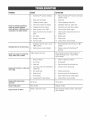
CaU$8'
Pumphasfollowing
problems:
failure to produce pressure,
erratic pressure, chattering, less
of pressure, bw water volume.
1.
HydroFoamTM launcherinstaIled.
1.
Replace HydroFoamTM launcher with high
pressure nozzb.
2.
Water inlet is blocked.
2.
Clearinlet.
3= Inadequate water suppiy.
3.
Provide adequatewater flow.
4.
Inlet hose is kinked or baking.
4.
Straighten inlet hose, patch ieak.
5.
Clogged inlet hose strainer.
5.
Checkand clean inlet hose strainer.
6.
Water suppiy is over IO0°F.
6.
Provide cooier water suppiy.
7.
High pressure hose is blocked or
leaks.
7.
Clearblocks in high pressure hose or
repiace hose.
8.
Gun leaks.
8.
Repiacegun.
9.
Nozzleis obstructed.
9.
Cleannozzle.
10. Pump is faulty.
10. Contact Sears service facility
1.
Detergent shut-off valve is in the
"Off" position.
1.
Rotate detergent shut-off valve to "On"
position.
High pressure nozzle installed.
2.
Replace nozzlewith HydroFoamTM
launcher.
Detergent fails to mix with spray.
Engine rune good at noqead but
"hogs" when meadis added.
Engine will not start; or starts and
rune rough.
Engine speed is too slow.
Move throttle control to FASTposition. If
engine stiii "bogs down", contact Sears
sen!be facility.
1.
Dirty air cleaner.
1.
Cleanor replace air cleaner.
2.
Out of fuel.
2.
Fill fuel task.
3.
Stale fuel.
3.
Drain fuei tank; fiii with fresh fuel.
4.
Spark plug wire not connected to
spark plug.
4.
Connectwire to spark plug.
5.
Bad spark plug.
5.
Replacespark plug.
6.
Water in fue!.
6.
Drain fue! tank; fill with fresh fuel.
7.
Overchoking.
7.
Open choke fully and crank engine.
8.
Excessively rich fuel mixture.
8.
Contact Sears service facility.
Engine shuts down during
operation.
Out of fuel.
Fill fuel tank.
Engine lacks power.
Dirty air filter.
Replaceair filter.
Choke is opened too soon.
Move choke to halfway position until engine
runs smoothly.
Engine "hunts" or falters.
23
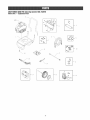
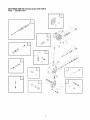
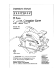
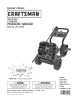
CRAFTSMAN3000 PSi CJeanJngSystem 580_752070
Main Unit _ ExpJodedView
--4
10
\
\\
79
_---16
11
-- 17
24
CRAFTSMAN3000 PSi Ctear_ingSystem 580,752070
Main Unit _ Parts List
item
I
2
3
4
5
6
7
8
9
10
11
12
13
Part #
202947GS
B196526GS
202948GS
195964GS
30809GS
197480GS
192131GS
196138GS
B2203GS
201758GS
201580RGS
201580XGS
201580AAGS
200595GS
192310GS
199955GS
198164GS
194298GS
23139DGS
202949GS
195454GS
200517GS
192050GS
item
14
15
16
17
Description
ASSY, Base
HANDLE
ASSY, Biiiboard/Decalswith Clips
Ctip, Tree
Grommet
KIT, Wireform
KiT, Pump Mounting Hardware
HOSE
KIT, HandleConnector
KiT, Nozzle
Nozzle, QC, Project Pro, Yetiow
Nozzle, QC, Project Pro, Orange
Nozzte,QC, Project Pro, Red
EXTENSION
KIT, Vibration Mount
KiT, CapChem
ASSY, Pump
Valve, Thermal Relief
Key
KIT, Wheel
Axie
Hubcap
E=Ring
Part #
198423GS
75246GS
199!17GS
199229GS
192980GS
900 NSP
Description
ASSY, Nozzle, Foaming
HHS,Trilobular, 3/8=16x 1=1/4
GUN
ASSY, Tank, Chem
Kit, Vaive
ENGINE(12S512=0119=B1)
items Not illustrated
Part #
194256GS
199462GS
AIO4ONGS
87815GS
203793GS
AB3061BGS
282829
202712GS
275034
202713GS
Description
KiT, TagWarning w/Ctip
BOTTLE,Cncntrt, Hydro Foam
HOSE,Chemicai, 24"
GOGGLES
MANUAL, Operator's
OIL BOTTLE
COVER,Static
DECAL,Recoil
LABEL,Warning
LABEL,Torquepower
Optionam
AccessoriesNotillustrated
7175187GS Garden Hose Quick Connect
7175!97GS
Accessory Quick Connect
7175124GS Rotating Brush Kit
7175122GS 30' Replacement Hose
7175116GS 0 Ring Repair Kit
7175129GS Turbo Nozzte
7175121GS 25' Extension Hose
7174402GS Hose Reel
6039
Pump Saver
6092
WASH, HydroFoamTM
6!35
KiT, HydroFoamTM Launcher & Wash
7174300GS House Wash Concentrate (makes 4 gaiions)
7174301GS Deck Wash Concentrate (makes 2 gaiions)
7174302GS Vehicle/BoatWash Concentrate (makes 4 gaflons)
7174303GS DegreaserConcentrate (makes4 galions)
7174307GS Mold/Mildew Concentrate (makes 2 gallons)
25
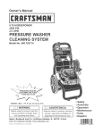
CRAFTSMAN3000 PSi CJeaningSystem 580_752070
Pump -- Exploded View
©
o
o
o
0
2G
CRAFTSMAN3000 PSi CJear_Jng
System 580,752070
Pump _ Parts List
item
19
28
45
62
76
A
B
C
D
E
F
G
H
J
K
L
Part #
190571GS
190574GS
190578GS
190581GS
194298GS
190594GS
190588GS
190589GS
19380BGS
193806GS
190592GS
190593GS
193807GS
189971GS
193971GS
193972GS
Description
CAP,Oil
MANIFOLD
PIN
CAP,!/8
THERMALRELIEF
KIT,UNLOADER
KIT,WATERH'JLET,
ANODIZED
KIT,OUTLET,
ANODIZED
KIT,HEADBRASS
KIT,CHECKVALVES
KIT,INLETCHECK
KIT,CHEMICAL
INJECTION
KIT,SEALSET
KIT,CHEMICAL
HOSE
KIT,PIPEFITTH'dG
KIT,UNLOADER
SEAT
items Net Hlustrated
190585GS
B2384GS
OIL BOTTLE
FILTER,Inlet
Optional Accessories
186452GS
FILTER,h_let,Bag of 10
NOTE:Item letters A o L are service kits and include all parts shown within the box.
27
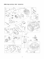
ENIINE, lri!gs
and Stratten, 12Sf12 - Explotet View
883
3_
10225!
993
7
10_
1029
1227 I
615 0
404
5o5®
[
616
2_
16
27o
24 [_
__
324
s2_
_
1102
0
741
1095 VALVEGASKETSET
883
868
51A
163
51
158 20
51B
28
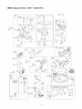
ENGINE, Briggs and Stratten,
12S512 - Exploded View
[
621
633
%
692
365
51A
108
51B
163
188
276 Q
127
95
5!
425
968
613
%
443
259
967
957
445
19o
525i
670
977 CARBURETOR
GASKETSET
601
276
51A
334
633 @)
163
524 A_
51_51
29
633A G
ENGINE, Briggs and Stratten,
12S512 - Exploded View
6o_
65 2
121CARBURETOR
OVERHAUL
KIT
58
55
592 ®
6O
121_
276 _
104 %_
633 _
633A @
134
51
51B
456
51A
597 8
127 (_
137
163
356
37
,/
78
?
305
592 ®
332 @
A:'F_:}_455
1005
1022
51
163
23
1_7528A42
]._
3O
ENGINE, Briggs and $tratten,
Item
1
2
3
4
5
7
8
9
10
11
11A
12
13
15
16
20
22
23
24
25
26
27
28
29
32
32A
33
34
35
36
37
40
43
45
46
51
51A
51B
55
58
69
65
78
95
97
104
108
109
117
118
121
122
125
127
130
133
134
137
163
187
188
190
192
202
209
222
227
238
259
276
287
300
304
305
306
307
332
Part #
697893
399269
299819S
498983
792381
697230
495786
699833
691125
691269
692937
692232
691137
691680
691457
399781S
691092
790116
222698S
791968
791326
791969
791324
691866
499423
499424
691664
695759
499642
499641
691304
691304
694086
692194
691997
690977
694039
692668
697735
692555
691421
691921
281434S
690837
691108
691636
499682
691242
691182
499681
497466
792383
792383
792382
698055
694468
691203
398187
398188
693981
691894
791766
691147
690940
694543
691303
691290
792397
690783
691300
691189
271716
690940
697590
499676
691108
691232
690345
690662
12S512 - Parts List
Bescdption
Cylinder Assembly
Kit-Bushing/Seal (Magneto Side)
£ Seal-Oil (Magneto Side)
Sump-Engine
Bead-Cylinder
£ 1-Gasket-Cylinder Head
Breather Assembly
£ Gasket-Breather
Screw (Breather Assembly)
Tube-Breather
Tube-Breather
£ Gasket-Crankcase
Screw (Cylinder Head)
Plug-Oil Drain
Crankshaft
£ Seal-Oil (PTO Side)
Screw (Engine Sump)
Flywheel
Key-Flywheel
Piston Assembly (Standard)
Piston Assembly (.020" Oversize)
Ring Set (Standard)
Ring Set (.020" Oversize)
Lock-Piston Pin
Pin-Piston
Rod-Connecting
Screw (Connecting Bed)
Screw (Connecting Rod)
Valve-Exhaust
Valve-Intake
Spring-Valve (intake)
Spring-Valve (Exhaust)
Guard-Flywheel
Retainer-Valve
Slinger-Governor/Oil
Tappet-Valve
Camshaft
¥ £ $ t Gasket-Intake
¥ £ $ t Gasket-intake
¥ £ $ t Gasket-intake
Housing-Rewind Starter
Rope-Starter (Outto Required Length)
Grip-Starter Rope
Screw (Rewind Starter)
Screw (Flywheel Guard)
Screw (Throttle Valve)
Shaft=Throttle
¥ Pin-Float Hinge
Valve-Choke
Shaft-Choke
Jet-Main (Standard)
Jet-Main (High Altitude)
Kit-Carburetor Overhaul
Spacer-Carburetor
Carburetor
¥ Plug-Welch
Valve-Throttle
Float-Oarbureter
¥ Kit-Needle/Seat
¥ $ Gasket-Float Bowl
¥ £ $ t Gasket-Air Cleaner
Line-Fuel (Out to Required Length)
Screw (Control Bracket)
Screw (Fuel Tank)
Bali-Rocker Arm
Link-Mechanical Governor
Spring-Governor
Bracket-Control
Lever-Governor Control
Cap-Valve
Bracket-Casing Clamp
¥ $ Washer-Sealing
Screw (Dipstick Tube)
Muffler
Housing-Blower
Screw (Blower Housing)
Shield-Cylinder
Screw (Cylinder Shield)
Nut (Flywheel)
Item
333
334
337
356
358
363
365
4O4
425
443
445
455
456
459
5O5
523
524
525
562
584
585
592
597
601
608
613
613A
615
616
619
621
633
633A
635
67O
684
689
692
718
741
830
832
836
836A
842
843
847
851
868
883
886
914
914A
Part #
802574
691061
692051
692390
792384
19069
691129
690272
690244
690255
697029
791960
692299
281505S
691251
499621
692296
495265
691119
697734
691879
690800
691696
791850
497680
691108
691140
690340
698801
691108
692310
693867
691321
66538S
692294
690345
691855
690572
690959
790345
694544
691466
691147
697551
691031
691884
692047
493880S
692044
691893
696268
691108
691127
957
966
967
968
972
975
977
993
1005
1022
1023
1026
1029
1034
1059
1095
1102
1210
1211
793606
690243
273356
691342
699374
493640
792385
694088
691346
691890
499624
692045
691230
691343
692311
792386
691255
498144
498144
£
¥
Included
Included
Included
Included
t
31
Bescription
Armature-Magneto
Screw (Magneto Armature)
Plug-Spark
Wire-Stop
Gasket Set-Engine
Puller-Flywheel
Screw (Carburetor)
Washer (Governor Crank)
Screw (Air CleanerCover)
Screw (Air CleanerPrimer Base)
Filter-Air CleanerCartridge
Cup-Flywheel
Retainer-Spring
Plate-Pawl Friction
Nut (Governor Control Lever)
Dipstick
£ Seal-O Ring (Dipstick)
Dipstick Tube
Bolt (Governor Control Lever)
Cover-Breather Passage
£ Gasket-Breather Passage
Nut (Rewind Starter)
Screw (Pawi Friction Plate)
Clamp-Hose
Starter-Rewind
Screw (Muffler)
Screw (Muffler)
Retainer-Governor Shaft
Crank-Governor
Screw (Cylinder Head Plate)
Switch-Stop
¥ :_:Seal-Choke/Throttle Shaft
¥ $ Seal-Choke/Throttle Shaft
Boot-Spark Plug
Spacer-Fuel Tank
Screw (Breather Passage Cover)
Spring-Friction
Spring-Detent
Pin-Locating
Gear-Timing
Stud-Rocker Arm
Guard-Muffler
Screw (Muffler Guard)
Screw (Muffler Guard)
£ Seal-O Ring (Dipstick Tube)
Lever-Sleeve
Dipstick/Tube Assembly
Terminal-Spark Plug
£ 1 Seal-Valve
£ 1- Gasket-Exhaust
Gasket Kit-Cylinder Head/Plate
Screw (Rocker Cover)
Screw (Rocker Cover)(Assemble in Number 1 and
Number 2 Positions)
Cap-Fuel Tank
Base-Air Cleaner Primer
Fiiter-Pre Cleaner
Cover-Air Cleaner
Tank-Fuel
Bowl-Float
Gasket Set-Carburetor
£ 1 Gasket-Cylinder Head Plate
Fan-Flywheel
£ 1- Gasket-Rocker Cover
Cover-Rocker
Rod-Push
Rocker Arm
Guide-Push Rod
Kit-Screw/Washer
Gasket Set-Valve
Pilot-Guide
Pulley/Spring Assembly (Pulley)
Pulley/Spring Assembly (Spring)
in
in
in
in
Engine Gasket SeL Item No, 358
Carburetor Overhaul Kit, Item No. 121
Carburetor Gasket Set, Item No. 977
Valve Gasket Set, Item No. 1095
Sears, Roebuck and Co., &S,A, (Sears), the California Air Resources Board ICARB) and
the United States Environmental Protection Agency {U,S,EPA)
Emissions CentromSystem Warranty Statement
ISwneCs Defect Warranty Rights and 8hmigations)
The California Air Resources Board (CARB), U.S. EPA and Sears are
pleased to explain the Emissions Centre[ System Warranty on your
srnaI[ offroad engine (SORE).hr California, new small ofroad
engines rnodel year 2006 and later must be designed, built and
equipped to meet the State's stringent anti-smog standards.
Elsewherein the United States, new non-road,spark-ignition engines
certified for mode[year 1997 and later must meet similar standardsset
forth bythe U.S. EPA.Sears must warrant the emissions control
system on your engine for the periodsof time listed below, provided
there has beenno abuse, neglector improper maintenanceof your
small of-road engine.
Your emissions centre[ system includes parts such as tire
carburetor, air cleaner, ignition system, fuel line, muffler and
catalytic converter. Also included rnay be connectors and other
emissions related assemblies.
*
*
*
,
,
b.
*
°
.
c
,
,
d.
*
,
Where a warrantable condition exists, Sears will repair your small
off-road engine at no cost to you including diagnosis, parts and
labor.
Carburetor and hrternal parts
Fuel Pump
Fuel line, fuel [hrefittings, clamps
Fue[tank, cap and tether
Carbon canister
Air Induction System
Air cbaner
Intake rnanl%d
Purge and vent line
Ignition System
Spark plug(s)
Magneto ignition system
Catalyst System
Catalytic converter
Exhaust manifold
, Air iniection system, Pulse valve
e. Miscellaneous Items
Sears, Roebuck and Co. Emissions Control Befects Warranty
Covera_je
Small of-road engines are warranted relative to ernissions control
parts defects for a period of two years, subiect to provisions set
forth below. If any covered part on your engine is defective,the part
will be repaired or replaced by Sears.
Owner's Warranty Responsibilities
As tire small of-road engine owner, you are responsible for tire
performance of the required rnaintenancelisted in your Operating
and Maintenance Instructions. Sears recommends that you retain all
your receipts covering maintenance on your small off-road engine
but Sears cannot deny warranty solely for the lack of receipts or for
your failure to ensurethe performance of all scheduled rnaintenance.
As the small off-road engine owner, you should however be aware
that Sears may deny you warranty coverage if your small of-road
engine or a part has failed due to abuse, neglect, improper
rnaintenanceor unapproved modifications.
You are responsible for presenting your small off-road engine to an
Authorized Sears Service Dealeras soon as a problem exbts.
The undisputed warranty repairs should be completed hr a
reasonable amount of time, not to exceed30 days.
If you have any questions regarding your warranty rights and
responsibilities, you should contact a Sears Service Representative
at 1-800-469-4663.
,
2.
3.
Vacuum, temperature, position, tirne sensitive valves and
switches
o Connectors and assernNbs
Length of Coverage
Sears warrants to the initial owner and eachsubsequent
purchaser that the Warranted Parts shahbe free from defects in
materials and workrnanship which caused the failure of the
Warranted Parts for a period of two years from the date tire
engine is deliveredto a retail purchaser.
No Charge
Repair or replacement of airy Warranted Part will be performed
at no charge to the owner, hrcluding diagnostic labor which
leads to the determhration that a Warranted Part is defective if
the diagnostic work ls performed at an Authorized Sears
Service Dealer.
4.
CJaims and Coverage Exclusions
Warranty claims shah be filed hr accordance with the provls_ons
of the Sears Engine Warranty Policy. Warranty coverage shall
be excluded for failures ofWarranted Parts which are not
original Sears parts or becauseof abuse, neglect or improper
rnaintenanceas set forth in the Sears Engine Warranty Policy.
Sears is not liable to cover failures of Warranted Parts caused
by the use of add-on, non-original, or rnodified parts.
5. _daintenanse
Any Warranted Part which is not schedubd for rephcement as
required rnaintenanceor which is scheduled only for regular
inspection to the effect of "repair or replaceas necessary"shall
be warranted asto defects for tire warranty period. Any
Warranted Part which is scheduledfor replacementas required
rnaintenanceshall be warranted as to defects only for the period
of time up to tire first scheduled replacernentfor that part. Any
replacement part that is equivalent in performance and
durabilityrnay be used in the perforrnanceof any maintenanceor
repairs. The owner is responsible for the performance of all
required rnaintenance as defined in the Sears Operating and
Maintenance Instructions.
6. Consequential Coverage
Coverage hereunder shall extend to the failure of any engine
components caused by tire failure of any Warranted Part still
under warranty.
The emissions warranty is a defects warranty. Defects are iudged
on normal engine performance. The warranty is not related to an inuse emissions test.
Sears, Ree#eek and Cn, Emissinns Cnntrni #efents Warranty
Prnvisinns
The following are specific provisions rebtive to your Emissions
Control Defects Warranty Coverage.It is in addition to the Sears
engine warranty for non-regulated engines found in the Operating and
MahrtenanceInstructions.
1. Warranted Parts
Coverageunder this warranty extends only to the parts listed
below (the emissions control systems parts) to the extent these
parts were present on the engine purchased.
a. Fuel Meterhrg System
* Cold start enrichment system
In the USA and Canada,a 24-hour hotlhre, 1-800-469-4663, has a rnenu of pre-recorded rnessagesoffering you product maintenance
hrforrnatlon.
32
EmJ_ion information
Certain engines wiii be certified to meet the United States
Environmental Protection Agency (USEPA)Phase 2 emission
standards. For phase 2 certified engines, the Emissions
Compiiance Period referred to on the Emissions Compliance
label indicates the number of operating hours for which the
engine has been shown to meet Federalemission
requirements.
Enginesthat are certified to meet the California Air Resources
Board (CARB) Tier 2 Emission Standards must display
information regarding the Emissions Durabiiity Period and Air
Index. The engine manufacturer makesthis information
avaiiabteto the consumer on emission iabeis, The engine
emission iabet wili indicate certification information,
For engines iess than 225 cc displacement:
CategoryC = 125 hours
Category B = 250 hours
CategoryA = 500 hours.
The Emissions Durability Period describes the number of
hours of actual running time for which the engine is certified
to be emissions compliant, assuming proper maintenancein
accordancewith the Operating & Maintenance Instructions.
The following categories are used:
For engines of 225 cc or more displacement:
CategoryC = 250 hours
Category B = 500 hours
CategoryA = 1000 hours.
Moderate: Engine is certified to be emission compliant for
125 hours of actual engine running time.
Intermediate: Engine is certified to be emission compliant
for 250 hours of actual engine running time.
Extended: Engine is certified to be emission compiiant for
500 hours of actual engine running time.
Forexample, a typical walk-behind lawn mower is used 20 to
25 hours per year. Therefore, the Emissions Durability
Period of an engine with an intermediate rating would
equateto 10 to 12 years.
33
GARANTIA
..........................................
REGLAS
DESEGURIDAD
............................
CARACTERiSTICAS
YCONTROLES
.......................
MONTAJE
........................................
OPERAC!ON
.......................................
ESPECIFICAC!ONE8
...................................
34
34-37
38
39-42
43-47
48
IVlANTEI',IIIVlIENTO
..................................
49-53
ALMACENAMIENTO ...................................
54
REPARAC!ONDE DA_@SREPUESTOS ....................
55
NOTA8 ...........................................
56-57
GARANTIADEL CONTROLDE EMBIONES ...............
COMOORDENARPARTES ...............
58-59
PAGINAPOSTERIOR
Garant_a ¢empieta de un a_e de _a_impiadera a presi6n Craftsman
Sila limpiadora a presiOn falls debido a defectos de materiales o rnalsode obra en el plazo de un aiio a partir de la fecha de compra,
devu61valaa cualquier almac@ Sears_punto de vents de Craftsman o centro de reparaci@ y repuestos de Sears de los Estados Unidos o
Canad_ pars su reparaci@ gratuita o en caso de que 6sta no sea posibb, pars su sustituci6n.
El periodo de garantia se reducir_ a 99 dias des@ la fecha de cornpra si la limpiadora a presiOn se utiliza en alg8n rnornento con fines
cornerciales o de alquibr.
Esta garantia le otorga deterrninados derechos legabs yes posible que tenga otros derechos que pueden variar de un pais o estado a otro.
Sears, Reebuek and Co,, Dept, 817 WA, Heffman Estates, JL 6elTg
Sears Canada Jnc,, Terente, entarie, Canada MSB 2B8
Este es emsimbob de abrta de seguridad, Esusado pars indieaHe situaeiones con peHgrospoten¢iabs de bsion pars e_
personal Siga masinstrueciones de todos bs mensajes de seguridad que aparecen despues de este simbob pars evitar posihbs
Jssione$
o lnuet'te,
I_I'
.... / Leaestemanualminu¢iosamentey ¢onezcaa rondolas
iL.:-_-.
I partesy eJf..¢b.amb.,o de s. m_q.l.a Hmpladoraa
presi6n.Cenezcasus apJieaeienes,sus Jimitaeienes
y Jes
peligrosinvoluerados,
Descarga El@trica
El sfrnbolo de abrta de seguridad (,_0 es usado con una palabra
(PELIGRO ADVERTEt,
ICIA PRECAUC!ON)_
u_smensajepor escrito o
una ilustraciOn, para alertado acerca de cualquier situaciOnde
peligro que pueda existir. PELt6RO indica un riesgo el cual, si no se
evita causafd la muerte o una heridagrave. ADVERTENCIAindica un
riesgo el cual si no se evita puedecausar la muerte o una herida
grave. PRECAUCm6N
indica un riesgo, el cual_si no se evita_puede
causar heridas rnelsoreso moderadas. AVISOindica una situaci@
Caer
SuperficiesResbalosas
Inyecci6nLfquida
que podria resultar en el da[io de! equipo. Siga los mensajesde
seguridad para evitar o reducir los riesgos de hefidas e inclusive la
muerte.
Partes en Movimiento
Fuego
34
Objetos Voladores
Explosi6n
Superficie6aliente
ManualdelOperario
Contragolpe
ADVERTENCiA
La gasolina y sus vapores son extrernadamente
inflamables
y exp!osivos.
severas e inclusive la muerte.
EI fuego o una explosion pueden causar quernaduras
PELiGRO
CUANDO ANADA cor_IBUSTmBLE 0
Su 6ontenidoes NOGIVO
0 FATALENCASODESER
/_
Apague el limpiadora a presi(_n(posici6n OFF)y d_jelo enfriar al menos
por 2 minutos antes de remover la tapa de la combustible. Afloje la
tapa lentamente para dejar que la presi6n salga del tanque.
INGERIDO.
Eviteinternarnente.
el contacto con
losrespirar
ojos la lapiel
o la o
ropa. No tornar
Evite
niebla
el vapor. La
exposici6nexcesiva de los oios o la piel
Mantengael estabilizador fuera
o Llene o vac[e el depOsito de combustible a la intemperie.
)uede causar irritaciOn.
del aIcance de los nifios.
El establlizador de combustible es un
qdmlcopeligroso.**
,
La tapa de combustible FreshStartTM esta diseflada para sostener un
cartucho el cual contiene el estabilizador de combustible.
,
EI',JCASO DE SERINGERIDO,Ilame un medico inmediatamente. No
induzca el v6mito. En caso de inhalaci6n salir al aire libre. En caso de
VACiEELDEP6SmTO
contacto con los ojos o con la piel, lavar abundantemente con agua
durante 15 minutos.
,
NO Ilene demasiado el tanque. Permita al menos espacio para la
expansi6n del combustible.
,
Si se ha derramado combustible, espere a que se evapore antes de
arrancar el motor.
,
Mantenga la gasolina alejada de chispas, llamas abiertas, pilotos, calor
y otras fuentes de ignici6n.
,
NO encienda un cigarrillo o fume.
CUANDO PONGA EN FUNCIONA{VIIENTO EL EQUBPO
o Almacene los cartuchos sin abrir en un area fresca, seca y bien
ventilada. Mantenga el cartucho abierto en latapa de combustible, y la
tapa de combustible cerrada en el tanque de combustible cuando no
est_ en uso.
o Compruebe que la bujfa el silenciador, el tap6n del dep6sito de
combustible y el filtro de aire estan instalados.
o NO arranque el motor sin la buj[a instalada.
CUANDO OPEBEELEQUmPO
o En caso de la emergencia, contacte a un mSdico inmediatamente y llama
1-800-424-9300 para la informaei6n material de la seguridad.
NO incline el motor o el equipo, de tal manera que la gasolina se pueda
derramar.
**El estabilizadorde combustiblecontiene2,6-di-tert-butilfenol(128-39-2)y
destiladodepetr61eoalif_tico(64742-47-8).
,
NO rocie I[quidos inflamables.
CUANDO TRANSPORTE0 REPAREELEQUIPO
o Transporte o repare el equipo con el tanque de combustible vac[o, o
con la valvula para apagar el combustible, apagada (posici6n OFF).
ABVERTENCiA
AI motor funcionar,se producemon6xidode carbono,
un gasinodoroy venenoso.
,
Respirarmon6xidode carbonopuedeprovocardolor
Almacene alejado de calderas, estufas, calentadores de agua, secadoras
de ropa u otros aparatos electrodom6sticos que posean pilotos u otras
fuentes de igniciOn, porque ellos puedeneneender los vapores de la
combustible.
de cabeza,n_useas,
ataques
fatiga, rnareos,
desmayosv6rnitos,
o incIuso
confusion,
la rnuerte.
Algunas sustancias
ser
perjudicialessi
quimicas o los detergentes
inhalados
IS_usea severa, desrnayando
o
pueden
ingeridos,causando
la
o para envenenar.
, Opere el limpiadora a presi6n SOLAMENTEal aire libre.
o AsegOresede que los gases de escape no puedan entrar por ventanas,
puertas, tomas de aire de ventilaci6n u otras aberturas en un espacio
cerrado en el que puedan acumularse.
,
Desconecte el cable de la buj[a.
CUANDO ALMACE_JE
0 GUARDE ELEQUmPOCON CO_vIBUSTmBLE
EN ELTANQUE
AIVEBTENCIA
_¢
NO arranque ni deje funcionar el motor en interiores ni en zonas
cerradas, aunque haya ventanas y puertas abiertas.
E! contacto con los cables eI_ctricos
iesgo de electrocuciOn.
electrocuciOn y quemaduras.
puedeprovocar
o NUNCA rode cerca de una fuente de energia el6ctrica.
o Utilice un respirador o mascara siempre que exista la posibilidad de
inhalar vapores.
o Lea todas las instrucciones de la mascara para asegurarse de que le
brindara la protecei6n neeesaria contra la inhalaciOn de vapores
nocivos,
35
ADVERTENCJA
ADVEBTENCJA
El retroceso (repliegue r_pido) del cable del arrancador
El chorro de agua a alta presi6n que este equipo
puede producir
produce
lesiones. El retroceso impedirA que el
usuario sueIte e! cable a tiernpo y tirar_ de su mano y
brazo Isacia el motor.
contusiones
)odriaF_dar lugar a la amputaciOn
de un rniernbro.
ubcutAiseos, provocando lesiones de gravedad que
La pistola rociadoFa contiene agua a aIta presi6n incluso
_
CornoresuItado,podrianproducirsefracturas,
puede atravesar la piel y los tejidos
o esquinces.
cots e! motor parado y el agua desconectada, que puede
causar la Iserida.
NUNCAtire del cable del arrancador sin eliminar previamente la presi6n
de la pistola rociadora.
Cuando arranque el motor, tire lentamente del cable hasta sentir una
resistencia y, a continuaciOn, tire r_pidamente de 81para evitar su
retroceso.
o NO permita en ningSn momento que NINOS operen la m_quina
limpiadora a presiOn.
o NUNOA repare la manguera de alta presi6n. Remplacela.
o Despu6s que cada tentativa que empieza, donde motor falla de correr,
siempre sdialar el fusil en la direcci6n segura y el disparador del fusil
del rocio del estruj6n para liberar la presi6n alta. Active el gatillo de la
pistola rociadora.
Sujete firmemente la pistola rociadora con ambas manos cuando
aplique un rociado a alta presi6n para evitar lesiones cuando se
produzca el retroceso de la pistola.
, ADVERTENCJA
,
NUNCA utilice ningOntipo de sellador para reparar una fuga en una
conexi6n. Sustituya la junta t6rica o la junta.
,
NUNCA conecte la manguera de alta presi6n al prolongador de la
boquilla.
,
Mantenga conectada la manguera a la m_quina o a la pistola de rociado
cuando el sistema est8 presurizado.
,
SIEMPRE que pare el motor, apunte con la pistola rociadora hacia una
direcci6n segura y apriete el gatillo para descargar la presiOny evitar el
retroceso. Active el seguro del gatillo cuando no utilice la pistola.
,
NUNCA apunte la pistola a la gente, animales o plantas.
o NO fije la pistola rociadora en la posici6n abierta.
Eluso de limpiadoraa presiOnpuedecrearloscharcos
y superficiesresba!osas.
E!retrocesode la pistolarociadorapuedeprovocar
caidas.
o NO abandone la pistola rociadora cuando la m_quina est6 en
funcionamiento.
o Utilice la limpiadora a presi6n desde una superficie estable.
,
NUNCA utilice una pistola rociadora cuyo seguro o protecciOn para el
gatillo no est8 en perfecto estado de funcionamiento.
,
AsegSrese en todo momento de conectar correctamente la pistola
rociadora, las boqnillas y los accesorios.
* El area de limpieza deber_itenet inclinaciones y drenajes adecuados
para disminuir la posibilidad de caidas debido a superficies resbalosas.
ABVEBTENCiA
o Extreme las precauciones si necesita utilizar la limpiadora a presi6n
desde una escalera, un andamio u otro lugar similar.
o Sujete firmemente la pistola rociadora con ambas manos cuando
aplique un rociado a alta presi6n para evitar lesiones cuando se
produzca el retroceso de la pistola.
OhispearinvolLmtario puede tenet como resultado el
¢
, ADVERTENCJA
EI contacto con la zona del silenciador
CUANDO AJUSTE O HAGA REPABACmONES A SU _VIAQUmNA
UMPmADOBAA PBESB{)N
puede producir
Siempredesconecteelalambrede la bujfay col6quelodondeno pueda
entrarencontactocon labuj[a.
CUANDO PRUEBE LA BUJiADEL _IOTOR
quemadurasgraves.
Los gases y el calor de escape pueden infiamar los
materia]es combustibles
y las estructuras
depOsito de combustible
y provocar un incendio.
o daiiar el
,
No toque las superficies calientes y EVITE los gases del escape a alta
temperatura.
,
Permita que el equipo se enfrie antes de tocarlo.
fuego o el golpe el6ctFico.
Utiliceun comprobadorde buj[ashomologado.
o NOcompruebalachispasin labuj[ainstalada,
o Deje un espacio mfnimo de 152 cm (5 pies) alrededor del limpiadora a
presi6n, incluida la parte superior.
o El C6digo de Normativa Federal (CFR,Titulo 36: Parques, Bosques y
Propiedad PL]blica)obliga a instalar una pantalla apagachispas en los
equipos con motor de combusti6n interno y a mantenerla en buenas
condiciones de funcionamiento, conforme a la norma 5100-1C (o
posterior) del Servicio Forestal de la USDA. Enel Estado de California.
la ley exige el uso de una pantalla apagachispas (Secci6n 4442 del
C6digo de Recursos P(_blicosde California). En otros estados puede
haber leyes similares en vigor.
36
AVl$O
ADVERTENCJA
El rociado de alta presi6n puede da_ar elementos fr_giles,
El arrancador
y otras piezas que rotan pueden enredar
las manos, el
pelo,la
incluyendoel vidrio.
ropa, o los accesorios.
NO dirija la pistola rociadora hacia un cristal cuando utilice la boquilla
MAX (punta de alfiler).
NUNCA apunte la pistola a plantas.
o NUNCA utilice la limpiadora a presi6n sin sus carcasas o tapas de
protecci6n.
o NO use ropa suelta, joyas o elementos qne puedan quedar atrapados en
el arranque o en otras partes rotatorias.
AVl$O
o Ate para arriba el pelo largo y quite la joyerfa.
El tratarnientoinadecuadodel limpiadoraa presi6npuededaiiado
acortarsuvida productiva.
ADVERTENCIA
Si usted tiene alguna pregunta acerca de las finalidades de uso del
generador, pregSntele a su concesionario o contacte a Sears.
NUNCA deber_inser operadas las unidades con partes rotas o ausentes
o sin la caja o cubiertas de protecci6n.
Riesgo de lesiones oculares
E! agua rodada
puedesalpicaro propulsarobjetos.
NO eluda ningOn dispositivo de seguridad de esta m_quina.
NO intente alterar la velocidad controlada.
o Utilice siempre gafas de protecci6n cuando utilice este equipo o si se
encuentra cerca de donde se est_ utilizando.
NO utilice la limpiadora a presiOnpor encima de su presi6n nominal.
NO haga ninguna modificaci6n en la limpiadora a presi6n.
o Antes de porter en marcha la limpiadora a presi6n, asegOresede Ilevar
gafas de protecci6n adecuadas.
Antes de poner en marcha la re%ulna limpiadora a presi6n en clima
frfo, revise todas las partes del equipo y asegLSresede que no se haya
formado hielo sobre elias.
o Utilice SIEMPRElas galas de segnridad apropiadas.
NUNCA mneva la m_quina halando la manguera de alta presi6n. Utilice
la manija que viene con la unidad.
Revise que el sistema de combustible no presente fugas o signos de
deterioro, como mangueras desgastadas o porosas, sujetadores flojos
o ausentes, tapa o tanque da_ados. Corrija todos los defectos antes de
operar la m_quina limpiadora a presi6n.
El equipo de alta presi6n est_ dise_iado para ser utilizado UNICAMENTE
con las partes autorizadas Sears. Si utiliza este equipo con partes que
no cumplan con las especificaciones m[nimas, el usuario asume todos
los riesgos y responsabilidades.
37
CONOZCA
$U iViAQUJNA
$JSTEiVIA
DELUVIPJEZA
..... Compare las ilustraciolses con su sistema de Ilrnpieza pare familiarizarse con las ubicaciones de los dlfereotes controles y ajustes.
Guarde este manual pare referencias futures.
Extensi6npareBoquillascon
R_pida
Pistola de Rociado
Lanzador HydroFoarnTM
Dep6sito de Lirnpieza
BoquillasProjectPro®
Arrancadorde Retroceso
Tanque del Combustible
Manguerade AltaPresl6n
Filtro de Aire
Tape del Dep6sito
del Acelte
Palancade Control de la
VAIvulade ReguIaciOny
Perilla del Cebador
Tome de Alta PresiOo&
Dstrada de Agua
J
Bomba equipado con AetornAtico se
Enffia Slstema
Arraneador de Retreeese - Usado para arrancar el rnotor
manualmente.
LaezaaerHydreFeamTM - Se utilizepara aplJcarHydroFoamTM u otro
detergelsteespecificopara lirnpiadorasa presiOn,
Aatem_tiee se Eefria Sistema - Los cic!os regan per bomba
cuando agua aIcanza 125°-155°F. Entibiar ague descargarA de la
bomba en el suelo. Este sistema previene el da#o interne de bomba.
B_laeguerade ANtePresi6e -Conecte un extreme ala pistola de
rociadoy el otro extreme ala tome de alta presiOn.
PaJaeca de Ceetrel de Ja\f_lvuJa de ReguJa¢i6n - Coloca el rnotor
en mode de arranque para el arrancador de retroceso y detiene el
rnotor en funcionarniento.
Bemba - Desarrolla aIta presiOnde ague.
BeqaiJ[as PrejeetPro® - Max General,y Suave para distintas
aplicaciones de lirnpieza.
PeriHa demCehader - Usada pare arranque de rnotores fries.
Dep6site de Limpieza- Permite almacenar haste 378 I[tros
(1 gal6n) de detergente para la lirnpiadora a presi6n.
PisteJa de Reciado - ControIa la aplicaciOnde agua sobre [a
superficie de limpieza con el gatillo. Inciuye cerrojo de seguridad.
Eetrada de Ague - ConexiOnpare la rnanguera de jardin.
Ten,lee del Cembustihle - Llene el tanqee con gasoline regular sin
contenido de ptorno en este punto.
Exteesi6e para BoquiJJasconCeeexi6e R_pida - Permite cambiar
entre tres boquJllasde rociado distintas y el lanzador HydroFoamTM.
Taps deJ Dep6site del Aceite -Uene e! motor con aceite aqui. Vea
la pAgina 51 pare las recomendaciones de! aceite.
Filtre de Aire - EI elemento de filtro ripe seco limita la cantidad de
suciedad y polvo que se introduce er_el motor.
Tame de AJta Presi6n - ConexiOnpare la rnanguerade alta presiOn.
38
Su sistema de lirnpieza requiere de cierto ensambIe y estar_ lista
para ser usado OnicamentedespuOsde haber depositado el
combustible y el aceite recomendado.
Si tiene probRemasconemensambmede su m_quina Hmpiadora a
presiOn,Hame a RamJneade ayuda de mam_quina Hmpiadora a
presiOnal 1=88{J1=222=3136.
Saque todo el contenido de la caja de carton, a excepciOnde la
lirnpiadora a presiOn.
2.
Abra completamente la caia de carton cortando cada una de
sus esquinas de arriba abajo.
3.
Saque la lirnpiadora a presiOnde la caia de carton.
Conecte manguera aatta presiOna pistola rociadoray a bomba.
Conecte e! suministro de agua a bomba.
8.
Conecte boquiIIa la extension al pistola rociadora.
9.
Selecto/conecta rdpido conecta boquilla a la extensi6n de la
boquilla.
Cenecte e! manuhrie y handeja acceseria
Desemhale Ja limpiadera a presiOn
1.
6.
7.
1. Coloque el mar_ubrio(A) sobre los soportes de! rnismo (B) que
ya estdn adheridos a la unidad principal. AsegOresede que los
orificios (C) en el manubrio estOnalineados con los odficios (C)
en los soportes de! rnismo rnanubrio.
Centenide de Ja ¢aja
Revise e! contenido de la cain. Si alguna de Ins partes no estA
presente o est,. da_ada [lame a la linea de ayuda de la rn_quina
limpiadora a presiOnal 1=80{1=222=3136.
o
,
o
La unidad principal
Manubrio con [irnpiar el tanque
Bandeja accesoria
,
,
La manguera de alta presiOn
Pistola de rociado
o
ExtensiOnde la boquilla con conector r_pido
,
o
Detergente HydroFoarnTM
Aceite para motor
o
Bolsa de partes (incluye los elementos descritos a continuaciOn)
o
Manual de[ operador
o
Tarjeta de la matricula
o
Gafasde seguridad
,
Manguera de sif6n de[ detergente
,
o
Bolsa con 3 boquillas de conexiones r_pidas multicolores
Lanzador HydroFoarnTM
o
Hoja de instrucciones del detergente y el lanzador
HydroFoamTM
Cartucho de combustible para rneiorar el arranque
Piezas para la rnal_ubrio(incluye Io siguiente):
o
Pernos del Soporte (2)
o
Perilla PIAstica(2)
o
,
o
NOTA:Talvez ser_necesariomoverlos soportesdel manubr{ode
un ladoa otro paraaIinearel manubriodetal rnaneraquepueda
deslizarsesobrelossoportesde!rnisrnomanubr{o.
2. Inserteel pernodel soporte(A) a trav_sde losorificiosdesde
fuerade la unidady sujeteuna periIIade plAstico(B) desdeel
interiorde la mismaunidad.Aprietemanualmente.
Co[oquela bandejadeaccesorios(A) sobrelosorificiosdel
rnanubrio(C) (vistadesdela partedelanterade la unidad).
PresioneIns pinzasdeArbol(B) paraintroducirIasen los
orificioshastaque quedena nivelconla bandejade accesodos.
Pinzas de _rbol (4)
Farniliaricesecon cada parte antes de ensarnblar la m_quina
limpiadora a presiOn.Compare e! contenido con la iIustraciOnde la
pAgina 38. Si alguna de la partes no est_ presente o se encuentra
dafiada, Ilame a la linea de ayuda de la m_quina lirnpiadora a
presJOnal 1=88{J1=222=3136.
MONTA,JEDEL$1$TEMA DE LIMPIEZA
J
Usted deber_ [[evar a cabo los siguientes procedirnientos antes de
poner en funcionamiento su sistema de limpieza
1.
Llene y rnande en tarjeta de rnatricula.
2.
Conecternanubrio y bandejaaccesoriaa unidad principal.
3.
Conecte la rnanguerade sifOn det detergente a la bornba.
4.
A_ada aceite al rnotor.
5.
A_ada gasolina al tanque de combustible.
Inserte Ins boquillas mLfltico!oresy el resto de los accesorios en
los espacios correspondientes de la bal_dejade accesorios.
Consulte Cdmo Usar la Bandeja de Accesorios.
39
Mentaje de mangeera de sif6n deJdetergente a
ADVERTENCiA
Ja homha
La lirnpiadoraa presi6n est_ equipadacon dos rnanguerasde
inyecciOnde detergente.U_sade elias estAconectadaa! depOsitode
limpieza,y la otra est_ sueItay se utiliza para i_lyectardetergentes
aptos para la limpiadora a presiOndesde una botella u otro recipier_te.
La gasolina y sus vaporus son extremadarnente
inflamables y explosivos.
_j_
Conecte una de las mangueras de inyecci6n de detergente (A) al
acoplamiento dentado de la rnar_guera(B) de la bornba.
severas
la rnuerte.
I fuego eo inclusive
una explosion
pueden causar quemaduras
CUANDO ANADA COI_IBUSTmBLE
EL DEPOSITO
o Apagueellimpiadoraa presiOn(posiciOnOFF)y dOjeloenfriaral menoe
pot 2 minutosantesde removerlatapade la combustible.Afloje la
tapalentamentepara@jar quelapresiOnsalga del tanque.
, LleneeldepOsitode combustiblea la intemperie.
o NOIlenedemasiadoeltanque.Permitaalmenosespacioparala
expansi6ndelcombustible.
o Si se haderramadocombustible,esperea queseevaporeantesde
arrancarel motor.
, Mantengala gasolinaalejadade chispas,llamasabiertas,pilotos,calor
y otrasfuentesde ignici6n.
, NOenciendaun cigarrilloo fume.
IMPORTANTE:SOlo se puede utilizar una de [asmangueras de
inyecciOn de detergente el_un rnornento dado. Cuando no se utilice
el depOsitode limpieza, aseg0rese de que la IIave de paso de
detergente de] depOsito de limpieza est6 en la posiciOn "Off".
agregue aceite de meter
1.
Co[oquela limpiadora a presiOn els una superficie plana y
nivelada.
2.
Limpie [a zona de ahededor de] orlficio de Ilenado de aceJtey
quite el tapOn amarillo.
Para evitar la forrnaci6n de carbonilla en e! circuito de combustible,
siempre que a_adacombustible, m_zcIelo con un estabilizador.
ConsuIte Almacenamiento. NO todos los combustibles son iguaIes.
Si detecta problemas de arranque o de rendirniento despuOsde
utiIizar un combustible pruebe a cambiar de proveedor o de mama.
Este motor estA certificado para funcionar con gasolina. Su sisterna
de control de emisiones es EM (Modlficaciones dd motor).
1.
2.
NOTA:Consulte la secciOn Aceite, para veF las recomendaciones
reIativas a! aceite. Compruebe que la botella de aceite suministrada
tiene la viscosidad adecuada para la temperatura ambiente actual.
3.
Lirnpie el area alrededor de la tapa de Ilenado de] combustible,
retire la tapa.
A_ada lentamente gasoIina sin plomo (A) al dep6sito de
combustible (B). NO a_adacombustible en exceso. Deje
aproximadamente 4 crn (1,5") de espacio (C) en et depOsito
para perrnitir la expansi6r_de] combustible, corno se muestra.
Con [a ayuda de un embudo (opciona[), vierta [entamente todo
e[ contenido de la botella de aceite por el orificio de Ilenado de
aceite.
AVl$O
El tratamiento inadecuado del lirnpiadora a presiOn puede dai_ar!o
' acortar su vidaloroductiva.
NOprocureacodarni empezarei motoranteshasido atendidoa
apropiadamente
con elaceiterecomendado.
Estopuedetenetcomo
resultadounaavefiadel motor.
4.
Vuelva a colocar el tapOny apri_telo firmernente.
Jf_f_f_f_f_f_f_f_f_f_f_f_
3. Instale[atapadeltanquude combustibley la esperaparaalgOn
combustiblerociadoparaevaporar,
iPRECAUCJ{}N!
Los combustibles
Agregue gaselina
con mezcla de alcohol (gasohol,
etanol o metano!) pueden atraer la humedad y provocar la
separaciOny formaciOn de _cidos duralsteel almacenamiento. Los
gases_cidos pueden dafiar el circuito de combustible y el motor
durante el almacenamiento.
B ¢ombustiMe dehe reunir mossiguientes requisites:
,
Gasolina sin plomo limpia y nueva.
o
Un rninirno de 87 octanos/87 AK] (91 RON). Para uso a gran
altitud, consulte Gran a/fitud.
,
El motor admite gasolina con hasta un 10% de etano! (gasohol)
o hasta un 15% de MTBE (_ter metil terbutflico).
Para evitar estu tipo de problemas, vacie e[ circuito de combustible
cualsdovaya a ahnacenar la unidad durante 30 dias o m4s. Vacie el
dep6sito de combustible, arranque e! motor y d@jdofuncionar hasta
que los conductos de combustible y e! carburador queden vacios.
Utilice combustible rmevo la pr6xima temporada. Para obtener m4s
lnformaci6na! respecto, consulte Almacenamiento.
AVIS@
Evite el da_o de! lirnpiadora a presiOn.
NUNCAutilice productos lirnpiadores para motores o carburadores
en el depOsito de combustible, ya que podrian provocar dafios
permanentes.
E! fracaso para seguir Manual de Operario para el combustible
reccomendations _arantia de vacios.
NOutilicegasolinano autorizada;por ejemplo,E85.
NOmezcleaceitecon gasolina.
NOmodifiqueelmotor parahacerlofuncionarcon otroscombustibles.
4O
Granaliilud
Tap6n de combustiblepara mejerar el arranque
El uso de colsservante de combustible rnantiene el combustible en
buen estado y limpia los carburadores, Io que facilita el arranque en
todas las estaciones del a_o. El nuevo tap6n de combustible gotea
autom_ticamente conservalsteconcentrado en el depOsito de
combustible.
Enaltitudessuperioresa 1.524metros(5.000pies),sedeber_
uti[izargaso%aconun minimode 85 octanos/ 85 AKI(89 RON).
Paraseguircumplielsdola normativasobreemisiones,es necesario
ajustarla unidadparasu usoa granaltitud.Deno realizarseeste
aiuste,el rendimientose reducir_y el consumode combustibley
lasernisionesaurnentarAn.
Paraobtenerm_.sinformaci6nsobree!
ajusteparagranaltitud,consu[teconun distribuidorcualificadode
Sears.No se recomiendautiIizarel motora altitudesinferioresa
762 rnetros(2.500pies)conel juegode gran altitud.
PELiGRO
,/////_v/_ INGERDO.Eviteel contactocon los ojos la pie!o la
ropa.[/o tornarinternamente.Eviterespirarla nieblao
el vapor.La exposici6nexcesivade los ojoso la piel
puedecausarirritaci6n.Mantengael estabilizadorfuera
del aIcalscede los ni_os.
Elestabilizador
decombustibleesunquimicopeligroso.**
Ceneete _a manguera y el suministre
la hemha
i
EI'_ICASO DE SERINGERIDO,Ilame un medico imnediatamente.
AVI$O
110hagafuncionarla bomba_e
En caso do la emergencia, contacte a un mSdico inmediatamente y llama
1-800-424-9300 para la informaci6n material do la seguridad.
*El estabilizador de combustible contiene 2,6-di-tert-butilfenol
destilado de petr61eo alif_tico (64742-47-8),
1.
de agua a
]
el surninistroconectadoyj
bierto.
(128-39-2) y
El da[io a la limpiadora a presi6n, resultado de la desatenci6n a esta
j
precauci6n, no ser4 cubierto por la garant[a,
j
NGTA:Antesdeconectarlasrnalsgueras,
retirey desecbelos
taponesde transportede la salidade altapresi6ny de la entradade
agnade la bomba.
Introduzcael cartuchoen el tap6n.
1.
Retrucedala rnangueraa altapresiOny conectea la basede la
pistolarociadora.Aprietecotsla mano.
/
2.
3.
Presionehastaqueel cartucboencajeen su posici6n.
Retirela lengOeta
paradeiarla membralsa
al descubierto.
ADVERTENCiA
El chorro de agua a alta presiOn que este equipo
_
I_IPORTANTE:
NOretireel cierrepIateadodel otto lado.
4. Vuelvaa co!ocare]tapOnde combustibleelse!depOsito.
subcut_neos
roduce, puedeatravesar
provocalsdola
lesiones
piel y los
de tejidos
gravedad que
_odriandar lugar a la arnputaci6n de un rniernbro.
, NUNCAconectelamangueradealta presi6nal prolongadordo la
boquilla.
, Mantengaconectadalamangueraa lam_quinao a lapistolade rociado
cuandoel sistemaest_ presurizado.
, AsegSrese
ontodo momentodecenectarcorrectamentela pistola
rociadora,lasboquillasy los accesorios.
CompruebeperiOdicamente
el cartuchoparaasegurarsede que
sigaconteniendoestabilizador
de combustible.Si est_vacio,
cambiee!cartuchopor uno nuevo.
41
Conecte e! otro extremo de la manguera a alta presiOn,a la
salida de alta presi6n de la bornba. Apriete con la mano.
5.
Conecte la rnanguera de jardin (no exceder 50 pies en la
Iongitud) a la entrada del agua. Apriete con B rnann.
AVIS8
Antesde queconectela manguerade jardina la entradade
agua,inspeccionee!cotadorde la entrada.Limpieel colador(A)
si tieneresiduoso solicitesu rempBzosi est,.daiiado.Re%rase
a la [email protected]
delosAnillos 'O_sila cohdordela
entradasedarhado.
NOhagafun€briar RaHmpiadnraa presi6n
si eJfiJtrode entradafaJtaoest_danado,
El uso de una%lvula unidireccional (igualador de presi6n o
vAIvula de retenciOn)en la entrada de la bornba puede producir
da_os en la bomba o en e! conector de entrada.
DEBEhaberun mfnimode3 metros(5 pies)de manguerade riego
libre entrelaentradade la limpiadoraa presiOny cualquierdispositivo,
comoun igualadorde presiOno unav_ilvulade retenci6n).
El da[ioa lalimpiadoraa presi6n,resultadode la desatenci6naesta
precauci6n,no ser_icubiertopot lagarantB.
6.
ABRA el agua apunte con la pistola hacia una direcci@ segura
y apriete el gati% para eliminar el aire y las impurezas det
sistema de bombeo.
ADVJ:RTF ClA
•
Riesgo
lesiones
oculares.
E! aguade
rociada
puede
salpicar o propulsar obietos.
. Utilicesiempregafasde protecci6ncuandoutiliceesteequipoo si se
encuentracercade don@seest_utilizando,
o Antesde poneren marchalalimpiadoraa presi6n,asegL3rese
de Ilevar
gafasde protecci6nadecuadas.
o UtiliceSlEMPRElasgalasde seguridadapropiadas,
-..
4.
Haga correr el agua a trav_s de la manguera de su jardin pnr
30 segLmdospara limpiar cualquier escombro que se
encuentre en ella. Desconecte el agua.
Lista de revisien previa al arranque del meter
Revise la unidad para asegurarse que ha Ibvado a cabo los
siguientes procedirnientos:
1. AsegQresede leer las secciones Redtasde Seduridady
Operaci6n antes de usar el sistema de B_npieza.
i_IPORTANTF: Hace 1/0 agua de parar de siphon para el
abastecirniento de agua. Useagua SOLOfria (menos que IO0°F).
42
2.
Revise que los sujetadores del carrete de la rnanguera est@
apretados.
3.
Revise que haya sido depositado aceitey est_ al nivel correcto
en la caja del cigOei_aldel rnotor.
4.
Deposite la gaso%a adecuada en e] tanque de! combustible.
5.
Revise quetodas las conexiones de las mangueras (alta
presi6n y sumirfistro de agua) est_n apretadas correctamente y
que no existan dobbces, cortes o da_o de la manguera de alta
presiOn.
6
Proporcione el saministro de agua adecuado (que no exceda
los IO0°F).
COMOUSAR$[J $JSTEMA#E LJMPJEZA
Para porter en mar€ha el sistema de Hmpieza
Si tiene probIemas cor_el funcionamier_tode su m_qui_a B_npiadora
a presi6n, por favor !lamea la B_eade ayuda de la rn_quina
Iimpiadora a presi6n al 1-888-222-3136.
Para darIe arranque a su sistema de limpieza movido a rnotor pot
primera vez siga estas instrucciones paso a paso, Esta informaciOn
acerca de la puesta en marcha inicial tambi6n es vAlida para cuando
vaya a darb arranque al rnotor despu6s de haberlo dejado la
rnAquina Bnpiadora a presi6n fuera de funcionarnier_topor Io
rner_osun dia.
UbJca¢i6n deJ Hmpiadera a presi6n
EspacJelJbre a#ededer del lJmpJaderaa presJ_n
1.
Coloque la rn_iquinalimpiadora a presi6n en un Area cercana a
una suministro de agua exterior capaz de abastecer agua a un
volumen mayor de 3.7 ga!oiBespor minuto en no menos que
20 PSI er_el fin de arandeb de presi6n de la manga de! jardin.
2.
Reviseque la manguera de aIta presiOnse encuentre conectada
firmemente a B pistola de rociado y a B bomb& Vea Montaje.
3.
AsegQreseque la unidad est8 nivelada.
4.
Conecte B rnanguera de jardin a la entrada del agua. Apfieteta
A#VENTENCJA
Los gases y el calor de escape pueden inflarnar los
rnateriaIes combustibles y las estructuras o dariar el
dep6sito de combustible y provocar un incendio.
, Dejeun espaciominimode 152cm (5 pies)alrededordel limpiadoraa
presi6n,ineluidala partesuperior.
COn la mano,
Coloque la limpiadora a presi6n a la intemperie en una zona en
don@ no se acurnubn gases de escape mortabs. AsegQresede que
los gases de escape (A) no puedas entrar por ventanas, pueltas,
tornas de aire de velstilaciOnu otras aberturas en un espacio
cerrado en el que puedan acurnuIarse.Tenga en cuer_talos vientos y
las corriente de aire preponderantes cuando elija la ubicaciOndel
limpiadora a presi@.
5.
[
Abra el agua, apunte con la pistola hada una direcci6n segura
y apriete e! gati% para eliminar el aire y las impurezas de]
sistema de bombeo.
Avlso
]
JNO haga funcionar la bomba_e
el suministro conectado yj
Jabierto.
j
F El da[iea lalimpiadoraa p_q6n, _sultadode la deeatenei6n
a esta 1
h precaucion,no ser4cubiertopor lagarantB,
j
h,A#VERTENCJA
AI motor funcionar, se produce monOxido de carbono,
un gas inodoro y venenoso.
6.
Respirar rnolsOxidode carbono puede provocar dolor
de cabeza,fatiga, rnareos,v6mitos, confusi6n, ataques,
nAuseas,desmayos o incluso la muerte.
, Opereel limpiadoraa presi6nSOLAMENTE
al airelibre.
o AsegQrese
de qaelosgasesde escapeno puedanentrarporventanas,
puertas,tomasde airedeventilaci6nu otrasaberturasen un espacio
cerradoen el quepuedanacumularse.
o NOarranqueni dejefuncionarel motoren interioresnien zonas
cerradas,aunquehayaventanasy puertasabiertas.
Acople la boquilla de extensi6n a la pistola aspersora. Apri_tela
manualmente.
El[ia [a boqu[lla ProjectPro® que desee usar, tire hacia atr_s
de! anillo de! prolongador de la boquilIa, inserte la boquilIa y
suelte el anillo. Tire de la boquilla para cornprobar que est_
bien rnontada. Consulte Cdmo usar el s,(stemade boquillas
ProjectPro@.
Fije el pesti% de seguridad (A) at d[sparador de la p[stola
aspersora.
43
9.
Mueva el control do la %lvula de admisiOn (A) a la posiciCn
"R_pido" ("Fast"), que se distingue con la figura de un conejo.
ADVERTENCJA
El retroceso (repliegue rApido) del cable dol arrancador
puede producir lesiooes. El retroceso impedir_ qee el
usuario suelto el cable a tiernpo y tirar_ de su rnanoy
brazo hacia el motor.
Como resultado, podrian producirso fracturas,
contusiones o esguincos.
, NUNCAtire delcabledel arrancadorsin eliminarpreviamentela presiOn
de la pistolarociadora.
, Cuandoarranqueel motor,tire lentamentedel cablehastasentir una
resistenciay, a continuaciOn,tire r_pidamentede61paraevitarsu
retroceso.
10. Muevala palaocadetahogador(B) a la posiciOn"Ahogado"
("Choke").
NOTA:Ene!casodo quo e! motorost_caliente,asegOreso
do que la
palancadelahogadorse encuentreen la posiciCn"Enrnarcha"
("Rue").
o DespuCsquecadatentativaqueempieza,deridemotorfallade correr,
siemprese_ialarel fusilen ladirecciOnseguray eldisparadordel fusil
del rode delestrujCnparaliberarla presiCnalta.Activeel gatillode la
pistolarociadora.
, Sujetefirmementela pistolarociadoracon ambasmanoscuando
apliqueun rociadoaalta presiOnparaevitarlesionescuandose
produzcael retrocesodela pistola.
IMPORTANTE:
Aistosde poooren marchala limpiadoraa presiOn,
asegOrese
deIlevargafasde protecciCnadecuadas.
ADVERTENCJA
Riesgo de lesiones ocelares
13. Cuaodo arranque el motor, mueva leotamente [a paIancade[
ahogador a la posici0n "En marcha" ("Run"). Si el motor faIIa,
mueva la palaoca a la posici0n "Ahogado" ("Choke"),y despu_s
a la posici6n "Eo marcha" ("Run").
E! agua rodada puede salpicar o propulsar objotos.
, Utilicesiempregalasde protecciCncuandoutiliceesteequipoo si se
encuentracercade dondeseest_utilizando.
, Antesde poneren marchalalimpiadoraa presiCn,aseg(Jrese
de Ilevar
gafasde protecciCnadecuadas.
, UtiliceSIEMPRE
lasgalasde seguridadapropiadas.
14. Si los fuogos de motor, pero no continOacotter, Prosioneel
disparador en la pistola para aliviar la presi6n interna de bomba.
Mueva la paIaocade! ahogador a la posiciOn "Ahogadd'
("Choke"),y repito los pasos 11 por 13.
11. Cuando arranquo el motor, colCquese en la posiciOn que so
recornienda a continuaciCn. Sujote la maoiia y halo ligoramento
la manija del arraoque hasta que sionta cierta resistencia.
Despu_s h_leta r_pidamente.
15. Si el motor no arraoca despu_sdo 6 tirones, mueva la palanca
dul ahogador a la posici6n "En marcha" ("Run"),y repito los
pasos 11 pot 13.
NOTA:Siompro rnantonga la control do %lvula de reguIaci6n on el
"Rdpido" ("Fast") posicione cu_ndo operar la limpiadora a presi6n.
ADVERTENCiA
El chorro de agua a aIta presiCn que este equipo
produce puedoatravesar la piel y los tejidos
_
)odriao dar lugar a la amputaciCn de un rniembro.
ubcut_neos, provocando lesiones de gravedad que
La pistola rociadoracontienoaguaa aIta presiCninciuso
con el motor parado y el agua desconectada,quopuede
causar la herida.
, NOpermitaen ningCnmomentoqueNINOSoperenlam_quina
limpiadoraa presiOn.
o Mantengaconectadalamangueraa lam_iquinao a lapistolade rociado
cuandoel sistemaest8 presurizado.
o NUNCAapuntela pistolaa lagente,animaleso plantas.
, NOfije lapistolarociadoraen laposiciCnabierta.
o NOabandonelapistola rociadoracuandolam_quinaest6 en
funcionamiente.
o NUNCAutiliceunapistolarociadoracuyoseguroo protecciOnparael
gatillo noest8en perfectoestadode funcionamiento.
o AsegCrese
entodo momentodeconectarcorrectamentela pistola
rociadora,lasboquillasy los accesorios.
12. Jale la cuerda de arranque leotamonte. NO permita que la cuerda
regrese bruscamootooo corltra del arrancador.
44
UtilizatiOn
ADVERTENCJA
La unidadest_equipadacon una bandejade accesorioscon
compartirnentos
paraguardarlas boquillasProiectPro®,el lanzador
HydroFoamTM_
la pistolarociadoray etpro!ongadorde la boquilla.La
partedelanterade la bandejatambi_nincluyeun ganchopara
sujetarla rnangueradealtapresiOn.
Elcontactocon la zonadel silenciadorpuedeproducir
quemadurasgraves.
Losgasesy el calorde escapepuedeninflamarlos
materialescombustiblesy lasestructuraso daiiarel
depOsitode combustibley provocarun incendio.
,
NOTA:El orificio adicionalde la bandejaperrniteguardarun cepillo.
La pinzaadicionalde la bandejapermiteguardarunaboquillaturbo.
La limpiadoraa presiOnNOincluyeel cepilloni la boquillaturbo
Puedeadquirirestoselementoscomo accesoriosopcionales.
1. Paseel prolongadorde la boqui!lapor el orificio de la bandeia
de accesoriosseg8nse indica.
1/0 toque las superficies calientes y EVITE los gases del escape a alta
temperatura.
o Permita que el equipo se enfrfe antes de tocarlo.
o Deje un espacio mfnimo de 152 cm (5 pies) alrededor del limpiadora a
presiOn, incluida la parte superior.
,
de la handeja de acceseries
El 66digo de Normativa Federal (CFR,Titulo 36: Parques, Bosques y
Propiedad PL3blica)obliga a instalar una pantalla apagachispas en los
equipos con rooter de combustion interne y a mantenerla en buenas
condiciones de funcionamiento, conforme a la norma 5100-16 (o
posterior) del Servicio Forestal de la USDA. Enel Estado de California.
la ley exige el use de una pantalla apagachispas (SecciOn4442 del
C6digo de Recursos P(_blicosde California), En otros estados puede
haber leyes similares en vigor.
C_me detener su sistema de limpieza
1.
Suelteel gatillode la pistola rociadoray dejefuncionarel
rnotoral ralent[durantedos minutos.
2.
Muevael aceleradora la posiciOn"Sinew"(Lento), luegoa la
posiciOn"Step" (Parada).
ADVERTENCIA
2.
Coloque la pistola rociadora en el orificio situado a la derecba
de la bandeja de accesorios.
3.
Inserte las boquillas de colores ProjectPro® y e! resto de los
accesorios en los espacios correspondientes de la bandeja de
accesorios.
4.
Inserte el lanzador HydroFoamTM en el espacio provisto a tal
efecto en la bandeia de accesorios, junto alas boquillas
ProjectPro® de colores.
5.
Cuelgue la manguera de alta presiOn del gancho situado en la
parte delantera de la bandejade accesorios, corno se rnuestra.
E!rnotorpodriapetardear,incendiarseo da_arse.
o NO coloque la palanca estranguladora en la posiciOn "l}hoke" para parar
el motor.
3.
SIEMPRE
fusil de puntoen unadirecciOnseguray el
disparadordel fusil del rociode!lestrujOnparaliberarla
presiOnretenidade la pleamar.
IMPORTANTE:
La pistolarociadoracontieneaguaa altapresiOn
inclusoconel motor paradoy el aguadesconectada.
COmeusar el sistema de hequilias PrejectPre@
LADVERTENCiA
Elconectorr_pidodel prolongadorde la boquillaperrnitecarnbiarla
boquillay rnontarunade lastres diferentesqueincluyeel sistema
ProiectPro®.Siernprequeest_activadoel segurode1gatillode la
pistolarociadorasepuedencambiarlas boquillasProjectPro®con
la limpiadoraa presiOnen funcionamiento.
Lasboquillas
ProjectPro®varianel presiOny patronde rociadocomose muestra.
El chorro de agua a alta presiOn que este equipo
produce puedeatravesar la piel y los teiidos
_
podrian dar lugar a la amputaciOn de un rniembro.
ubcut_neos, provocando lesiones de gravedad que
La pistola rociadoracontieneaguaa alta presiOnincluso
con el motor parado y el agua desconectada,qoe puede
caosar la herida.
La PresiOn alta
o Mantengaconectadalamangueraa lam_iquinao a la pistolade rociado
cuandoel sistemaest8 presurizado.
o SIEMPREquepareel motor,apuntecon la pistolarociadorahaciauna
direcciOnseguray aprieteelgatillo paradescargarla presiOny evitarel
retroceso.Activeel segurodelgatillo cuandono utilicelapistola.
4.
Active el seguro de! gatillo de la pistola rociadora cuando no la
utilice.
\-_..[
..................
.,
Suave
400Amarillo
2350 PSI
2.7 GPM
45
General
150 rtaranja
2675 PSI
2.5 GPM
Max
O° Roja
3000 PSI
2.3 GPM
Par++memb++++
J+s+m+qmiJJa+
Preje+tPr+®, ++_jae+tm++
in+f_r+c+i+n++: 4.
1. Ooloqueel pestillode seguridadde la pistolade rociado.
2. Desplacehaciaarrase! anillodel co!lectorrApidoy tire de las
5.
boquillasProjectPro®.GuardelasboquillasProjectPro®en el
soportede la bandeiade accesorios.
ADVERTENCiA
6.
n que este equ_po
I y los tejidos
nes de gravedad que
6n de un miembro.
NUNCAintercambieboquillaProjectProLF_)
sinhaberaseguradoel
cerrojode seguridaddel gatillo.
NOtuerzaboquillaProjectPro(®
al rociar.
DespIacehaciaatr_sel anillo,insertela boquiIlaProjectPro@
eIegiday suelteel aniflo.Tiredela boquillaProjectPro®para
comprobarqueest_bienmontada.
Parauna lirnpiezam_s efectivarnantengala boquiIIade
rociadode8 a 24 pulgadasde la superficiede limpieza.Si
colocala boquillarnuycerca,podriadariarla superficieque
estAlirnpiando.
1/0co]oquela boquillaa menosde 6 pulgadascuandoest6
lirnpia+sdo
Ila_tas.
C+m+ atilizar el +aazader HydmF+am
TM
El conector r_pido del prolongador de la boquilla permite conectar
e! lanzador HydroFoarnTM. Utilice e! lalszador HydroFoarnTM para
apIicar detergente HydroFoamTM u otro +impiadora fin de eliminar
rnejor la suciedad rn_s resistente de unavariedad de superficies.
Eli]ala boquillaPro]ectPro®quedesee:
•
Paraun enjuagadosuave(bajapresiOny mayorcaudal),
parauna limpiezasuavede coches/camiones,
barcos
RVs,rnueblesdejardfn cortac_spedes,
etc, seteccionela
boquillaProjectPro®amarillade suave.
Siva estas insf[mcci+nespara ¢+nectar el lanzader HydmF+am+r':
1.
Coloque el pestillo de seguridad de la pistola de rociado.
2.
Desptacehacia atr_s el anillo de] conector r_pido y tire de las
boquillas ProjectPro®. Guarde las boquillas ProjectPro® en el
soporte de la bandejade accesorios.
3.
Tire hacia atr_s del ani% inserte el lar_zadorHydroFoarnTM y
suelte el anillo. Tire del lanzador HydroFoamTM para comprobar
que est,. bien montado.
mMPORTANTE:
Consulte tambi6n la hoja de instrucciorles del
lanzador y el detergente HydroFoamTM:contiene instrucciones
importantes de uso.
Para un enjuagado general (rnedia presi6n y medio
caudal) id6neo para la mayoria de las limpiezas, como
revestirnientos exteriores, patios de ladrillo, sue!os de
madera entradas, aceras, suelos de garaje etc.,
seleccione la boquilla ProjectPro® narania de general.
Limpieza y Apiicaei_n del Detergente
PRECP,tJ[}I+JJ
Los productos qdmicos pueden provocar les[ones de gravedad
_/o da_os materiaIes.
NUNCAutiliceliquidosc_usticoscon la limpiadoraa presi6n.
UseEXCLUSIVAMENTE
detergenteso jabonesespecialespara la
limpiadoraa presiOn.Sigatodaslas instruccionesdelfabricante.
Para aplicar el deter_ente, siva les si_luientespas+s:
Paraun enjuagadode rn_xirnapotencia(altapresiOny
bajocaudal),parasuperficiesrebeWeso dediffcil acceso
cornosuperficiesde plantasaltas,elirninaci6nde pintura,
manchasde aceite eliminaciOnde 6xidou otras
sustanciasdificiIes(alquitr_n resina,grasa cera,etc.),
seleccionela boquillaProjectPro®roja de rn_xirna.
1.
Conecte una de las rnanguerasde inyecciOnde detergente
conforrne alas instrucciones que se detaIlan en la secciOn
Conecte la manguera de irryecci6n de deterdente a ta bomba.
2.
Repaseel uso de la boquilla ProjectPro® y del lanzador
HydroFoamTM.
3.
Prepare el detergente HydroFoamTM conforme alas
instrucciones que se indican en la botella o prepare una
soluci6n de detergelsteadecuada para el trabajo a realizar.
4.
Aseg(_resede que la Ilave de paso de detergente del depOsito
de lirnp[ezaest_ en la pos[ciOn "Off".
5.
Si utiliza un depOsito de lirnpieza, vierta detergente en su
interior.
NOTA:La capacidad del dep6sito de limpieza es de 3,78 I (1 gaI6n).
6. Aseg(_resede que el lalszador HydroFoamTM estA instalado.
NOTA:1/0 se puede aplicar detergente con las boquillas de alta
presiOn (Amarilla, Narania y Roja).
46
7.
Aseg0rese de que la rnangueradel jardin est_ conectada a la
entrada de agua. Cornpruebe que la rnanguera de alta presi0n
est_ conectada a la pistola rociadora y a la bornba. Abra la
alimentaciOnde agua.
Para Lm mejor resultado, friegue la superficie recubielta cots
HydroFoamTM detergente para eliminar mAs f_cilmente la suciedad y
las rnanchas mAs resistentes. Para limpiar vehiculos, utiIice un
cepfllo o una rnanopla suave para coches. Para limpiar terrazas
revestimientos exteriores y horrnigOn, utilice un cepfllo adecuado
para la cada superficie.
AVI$O
Usted deber_ conectar todas las mangueras antes de darle
_ue
al motor.
Arrancarel motorsintenertodaslas manguerasconectadasy sin el
suministrode aguaABIERTO
(ON)causar_eldafiode la bomba.
El da_oa lalimpiadoraa presi6n,resultadode la desatenci6naesta
precauci6n,no ser_cubiertoporla garantia.
8.
mI_IPORTANTE:
Si utiIiza la manguera de inyecciOn de detergente,
limpie el circuito de inyecci6n de detergente despu_s de cada uso.
Para ello, coloque el filtro en un cubo de agua fria y haga funcionar
la limpiadora a baja presiOn durante 1 O2 minutos.
Enjuage de la M_quina Limp_adera a Presi6n
Active el seguro del gatillo de la pistola rociadora y ponga en
marcha el motor siguiendo las instrucciones de la secciOn
Cdmo poner en funcionamiento /a fimpiadora a pmsi6n.
Bespuds de llaber apiicade el deter_enie, refrie_ue Hasuperficie
y enjua_lela de Hasi_juiente lnanera:
1. Coloque el cerrojo de segufidad a la pistola de rociado.
9A. Si utiliza el depOsito de limpieza, gire la Ilave de paso de
detergente del depOsito hasta la posiciOn "On" (A).
2.
AsegOresede que la %lvula de paso de detergente estA en la
posici6n "Off".
3.
Quite e[ lanzador HydroFoarnTM del prolongador de la boquilla.
4.
Seleccione e instaIe la boquilla de alta presi6n deseada
conforme alas instrucciones de la secciOn C_mo Usar el
Sistema de Boquillas ProjectPro®.
5.
Mantenga la pistola de rociado a una distancia segura del _rea
que planea rociar.
IMPORTANTE:Si utiliza una rnanguera de inyecci6n de detergente,
aseg0rese de que [a [lave de paso de detergente del dep6sito de
limpieza estA en la posici6n "Off".
ABVERTENCIA
9B. Si utiIiza una manguera de inyecci6n de detergente, coloque el
extremo de! fiItro peque_o del tubo de inyecci6n de detergente
en el recipiente del detergente.
E! retroceso de la pistola rociadora puede provocar
caidas.
NOTA:AsegOresede que el filtro est_ totalmente surnergido
mientras se aptica el detergente.
Utilice la limpiadora a presi6n desde una superficie estable,
o Extreme las precauciones si necesita utilizar la limpiadora a presi6n
desde una escalera, un andamio u otro lugar similar.
AVlSO
El contacto con el silenciador a alta temperatura puede producir
da_os en el tubo de inyecciOn de detergente.
Cuandocoloqueel filtro en labotelladeidetergente,coloqueeltubo de
maneraqueno entreen contactoaccidentalmente
con elsilenciador
caliente.
o Sujete firmemente la pistola rociadora con ambas manos cuando
aplique un rociado a alta presiOn para evitar lesiones cuando se
produzca el retroceso de la pistola,
10. ApIique HydroFoamTM detergente a una superficie seca.
Empiece por la pasteinferior y suba haciendo rnovirnier_tos
largos, uniformes y repetitivos.
6.
Ap[iqueLmrociadode altapresi6na unapeque_azonay luego
compruebesi seha producidoalgOntipo de da_o.Si no
apreciadaiios,continOeen el paso7.
7.
Cornienceen la partesuperiorde!areaqueva a en]uagar,
dirigi6ndosehaciaabajocon los rnisrnosmovirnientos
superpuestosque utiliz6parala lirnpieza.
NOTA: Para evitar la formaciOn de mamas de gotas de agLlaen
vehiculos, trabaje en una zona de sornbra y deje enfriar las
superficies antes de ernpezar.
$iste_a
11
{Ali ie T r iee}
Deje qLleel HydroFoamTM detergente empape la superficie
durante 3-5 minutos antes de lavar y aclarar. Vuelva a apIicar
la soluci6n cuando sea necesario para evitar que la superficie
se seque. Evite que e! HydroFoarnTM detergente se seque
(impide la formaci6n de vetas).
de Enffia_iente A_te_dtice
E]agua que circu[a dentro de la bomba puede alcanzartemperaturas
entre los 125°-155°F s[ hacefuncionar el motor de su m_quina
limpiadora a presiOn de 3 a 5 minutos sin oprimir el gatiI[o de [a
pistola de rociado. E[ sistema de enfriamiento autom_.ticose activa a
esta temperatura y enfria la bomba descargando agua caliente en el
piso, evitando asi el daiio [nterno de la bomba.
47
JNFORMACI6NTECNmCA
$OBREEL MOTOR
ESPECJFJCACJONE$
DEL PRODUCTO
El motor es de uno cilindros, de vA[vulasen cabeza (OHV),
rdrigerado por aire y de baja emisiOn.
Especificacienes de _a_a_quina Limpiadora a
Presi6n
En el Estado de California, los motores de la 120000 ban obtenido la
certificaciOn del California Air Resources Board (Conseio de
recursos de aire de California) de cumpIimiento de la normativa
sobre emisiones durante 125 horas. Esta certificaciOn no supone
para el comprador, el propietario o e! LIsuarioninguna garantia
adicional en !o relativo a] rendimiento y a la vida t_til del motor. Las
garantias de! motor ata_en exck_sivamenteal producto y alas
emisiones que se declaran en este manual.
PresiOnde salida maxima
3,000 PSI
Caudal rn_tx[rno..................................
2.7 GPM
Mezclade quimicos ..................
UsesegOninstrucciones
Temperatura del surninistro
de agua ............................
Que no exceda los IO0°F
Peso que Embarca .................................
71 Ibs.
Petencia Nominal
Especificacienes del Meter
El valor de potencia bruta de cada mode[o de rnotor de gasolina se
indica en la etiqueta conforme a los requisitos del cOdigoJ1940
(Procedimiento de vaIoraciOnde potencia y par de pequeiios
motores) de la SAE (Society of Automotive Engineers, Sociedad de
ingenieros de automociOn). Los valores norninales se han obtenido
y correoido conforme al cOdigoSAE J!995 (RevisiOn2002-B5). Los
valores de par se obtienen a 3060 rpm, y los va!ores de potencia, a
3600 rpm. La potencia bruta real del motor serAinferior y
dependerA,entre otros factores, de las condiciones ambientales de
uso y de [as variaciones entre distintos rnotores del mismo mode[o.
Dada la arnplia variedad de productos que utilizan nuestros motores
y la multitud de factores arnbientales que pueden afectar a su
funcionamiento es posibIe que e[ motor de gasolina no desarrolle
toda su potencia bruta nominal en determinados equipos (potencia
real "in situ"). Esta diferencia se debe, entre otros, a los siguientes
factores: accesorios (fiItro de aire, escape, carga, refrigeraciOn,
carburador, bomba de combustible, etc.), lirnitaciones de la
aplicaciOn,condiciones ambientaIes de uso (ternperatura, hurnedad,
altitud) y variaciones entre distintos rnotores de Lm rnismo mode[o.
Briggs & Stratton podrA sustituir e! rnotor de esta serie por otto de
mayor potencia nominal en caso de lirnitaciones de fabricaciOn o
capaddad.
DiAmetro de camisa ...................
68 rnm (2,69 pulgadas)
Carrera .............................
52 rnm (2,04 pulgadas)
Desplazarniento ......................
190 cc (11,57 pulgadas)
Buiia
Tipo: ..........................
Briggs & Stratton 491055S
Cal[brar SeparaciOna: .............
Entrehierro del inducido: .......................
0.020 pulgadas (O.50mm)
0,15-0,36 rnm
(0,006-0,014
pulgadas)
Holgura de la vAIvulacon mueIIes de vAIvula instalados y piston de
6 rnm (0,25 pulgadas) pasado el punto rnuerto superior (comprobar
con el rnotor en fr[o)
AdrnisiOn ...............
0,10-0,15 rnrn (0,004-0,006 pulgadas)
Escape .................
0,10-0,20 rnrn (0,004-0,008 pulgadas)
Capacidad de Gasolina ..........................
Capacidad de Aceite .....................
1.6 Cuartos
0.65 litros (22 onzas)
NOTA:Para un rneior funcionamiento, la carga de potencia no debe
superar el 85% de la potencia nominal. La potencia del motor se
reducir_ un 35% por cada 300 rnetros (1.000 pies) de altitud y un
1% por cada56 °C (10 °F) a partir de 25 °C (77 °C). FuncionarA
satisfactoriamente en un Angulo de hasta 15°.
48
RESPONSABJLIDADE$
#EL PRSPIETARJO
Siga el programa de mantenimiento seg@ e] ROrnerode I_oraso segOnel calendario, [o que suceda pr[mero. Se requbre de servicio con
mayor frecuencia cuando opere la uRldad enlas condiciones adversas descritas a continuaci6o
TAREA DE MANTENIMIENTO
INTERVALO DE OPERACIONPOR HeRA
Antes de
Cada 25 Horas o
Cada 50 Horas o
Cada 100 Horas
Cada Uso
al A_o
al A_o
o al Aiio
FECHAS DE SERVICIO
I 100-300
Horas
limpiadera a presi6n
Revisdlimpie el filtro de la entrada de agua
Revise la manguera de alta preside
×
Revise la manguera del detergente
×
Revise la pistoia aspersora y verifique que no
haya fugas en el ensamNaie
×
Prepare la bomba para almacenada a menos de
32°F
Yea Alrnacenamiento en el Inviemo,
Motet
Vedficar el nivel de aceite
Limpie los residuos
X
X
Cambiar el aceite del motor
X_
Servicio al filtro de aire
X_
X
ServMo a la buj[a
X
Servicio al sistema de la buj[a
X_
Limpie el sistema de refrigeraci6n
Limpieza de la c_mara de combusti6n
E
Prepar almacenambnto
Si la unidad permanecer& sin uso por m_s de 30 dias,
Limpiar si est_ obstruido, Remplazar si est_ perforado o roto,
Cambiar el aceite despuSs de las primeras (5) horas y despu@ eada 50 horas, Hacer el eambio de aceite con mayor frecuencia cuando trabaje en condiciones de
mucha suciedad o polvo.
Remplazar m_s a menudo bajo condiciones de sueiedad o polvo,
RECOJVJEN#ACIONE$
GENERALE$
CONTROLBE EJVilSJONE$
El rnaRtenimbnto peri6dico meiorar_ e[ rendlrniento y prolongar_ la
CualqLfierestablecirnieRto o indMduo especializado en [a reparaci6n
de rnotores que no sear de automoclOn puede encargarse del
rnantenimiento, la sustituciOn y [a reparaci6n de los dispositivos y
sisternas de control de emislones.
vidaOtilde![lmpladora
a presi6n.Acudaa un distribuidorautorlzado
de Searsparareparar[a uRidad.
La garantiade la mAqulnaB_npiadora
a presiOnNOcubrelos
elernentosque hansidosujetosa abusoo neg[lgenciapor partedd
ANTESBE CABAUSe
operador. Para hacer vAllda [a cobertura total de la garantia, el
operadordeberdrnantenerla [avadora
de presiOnta[ y como se
1.
Reviseel nivel de aceite del motor.
indica en e[ manual, lncluyendosu adecuado almacenamieoto,
como se describe en la secci@ Almacenambnto.
2.
Llmpie los residuos.
3.
Revisesi existen da_os en el colador de la entrada de agua.
4.
Revisesl existen da_os en el tanques de quirnicos.
5.
Compruebe sl los depOslto de B_npbzaestdn da_ados.
6.
Revisesi existen fugas eo el conjunto de la exteRsiOnpara
boquillas y plstola.
7.
Ellmlne el aire y los contaminantes de B bomba.
AlgunosaiustestendrAnquehacerseperi6dlcamente
pararnantener
adecuadamentesu rnAqulna [lrnpladoraa preslOn.
Todoslosservidosy ajustesdeber_nhacersepor Io rnenosunavez
en cada estaciOn.Siga las instrucciones de la taNa "Programa de
Mantenimiento"descdtaanteriormente.
NOTA:Unavez al aiio, usteddeberAlimpiaro remplazarla bujiay el
%ro de aire.Unabuiia nuevay un %ro de aireB_nplogarantizan
una rnezcladecombustibb-aireadecuaday b ayudaa su motor a
fuocionarmeiory a tener unavida 8til m_s prolongada.
49
MANTENJMJENTODE LA MAQUiNA
LAVADORAA PRESJON
Mantenimiente
Si siente una sensaciOnpuIsante al momento de apretar e! gatiI[o de
la pistoIa rociadora puede que sea causada pot la presiOnexcesiva
en la bomba. La causa principal de [a presi6n excesiva en la bomba
es cuando la boquilla se encuentra atascada o tapada con materiales
extra_os tales como tierra, etc. Para corregir el problema [irnpie
[nmediatamente la boquilIa siga las instrucciones siguientes:
Lhnpie los Residues
Lirnpie a diario, o antes de cada uso, los residuos acumulados en e[
limpiadora a presi6n. Mantenga limpias las conexiones, los muelles
y los rnandos. Limpie todo resto de combustible de la zona que
rodea al silenciador y de detrAs del mismo. Inspeccione las ranuras
para aire de enfriarniento y la apertura del limpiadora a presi6n.
Estas aperturas deberAnmantenerse lirnpias y despeiadas.
Mantenga limpios los cornponentes del limpiadora a presiOn para
reducir el riesgo de sobrecalentamiento e igniciOn de los residuos
acumulados.
de la RequHla
1.
Apague el motor y apague e[ surninistro de agua.
2.
Remuevala boqufila del extremo de la extension de la boquilla.
3.
Useel peque_o sujeta papeIes para liberar cualquier material
extraiio que est_ tapando la boquilla (A).
4.
Usando una rnanguera de jardin, rernuevacualquier desecho
adicionaL poniendo agua en la extension de la boquilla. Haga
6sto de 30 a 60 segundos.
Utilice un trapo hBmedo para limpiar las superficies exteriores.
AVIS8
E]tratamiento [nadecuadode[ lirnp[adora a presi6n puede daiiaflo
' acortar su vida productiva.
NOinsertecualquierobjetoa tray,s de lasranurasde enfriamiento.
Puedeusarun cepfllodecerdassuavespara retirarla suciedad
endurecida,aceite,etc.
PuedeusarunamAquinaaspiradoraparadirninar suciedady
residuossueltos.
Revise y Limpie el Ceiader de Entrada
Examine el coIador de entrada de [a rnanguera de jardin. Limpielo s[
estA tapado o rernplacelo siestA roto.
Revise Ja Manguera de AIta Presi6n
Las mangueras de alta presiOn pueden desarrollar fugas debido al
desgaste, dobleces o abuso. Revisela manguera antes de cada uso.
Revise si existen cortes fugas abrasiones levantamiento de la
cubierta, da_o o movimiento de los acopIamientos. Si exJste
cuaIquiera de estas condiciones, remplace la rnanguera
inrnediatamente.
Revise la Pistela y la ExtensiOn para Requitlas
Examine la conexiOnde la manguera a la pistola y cemiorese de que
est_ en buen estado. Pruebe el gatillo oprimiSndolo y asegur_ndose
de que se devuelve a su sitio cuando Io suelte. Coloque el cerrojo de
seguridad en la posiciOn UP y pruebe el gatillo. Usted no debe ser
capazde oprirnir el gatiIIo. Remplace la pistola inrnedJatarnentesi
falla cualquiera de estas pruebas.
5=
Instale de nuevo la boquilla en [a extensi6n.
6.
Conecte de nuevo la extensi6n de la boquflla a la pistola
rociadora.
7.
Conecte de nuevo el surninistro de agua, prenda el agua, y
eneienda el motor.
8.
Pruebeel [avador
a presi6nal hacerfuncionarconcadaunade
lasboqufllade conexionesrApidasquevieneconel lavadora
presi6n.
Niantenimiente de los Anilios'0'
Compre una O-Juego de ReparaciOnde Anillo en sus Sears locales
o %mando l=800=4=_IY=HO_IE
(46g=4663}o en linea en
www.sears.com. No se incluye con la arandela de la presiOn. Este
juego incluye !os anfllos del reernpIazoO, arandeIa de caucho y filtro
de cala de agua. Re%rase a la hoia de la instrucci6n proporcionada
en el juego para atender a su unidad'los anillos de s O.
,_
, ADVERTENCiA
ADVERTENCiA
El chorro de agua a alta presiOn que este equipo
El chorro de agua a alta presiOnque este equipo
produce, puedeatravesar la piel y los tejidos
subcut_neos, provocando lesiones de gravedad que
podfian dar lugar a la amputaci6n de un miembro.
1_
subcutAneos,provocando
produce,
puedeatravesar JapieJy
lesioneslos
de teiidos
gravedad que
_odriandar lugar a la amputaci6n de un rniernbro.
o NUNCAreparaci6nquesalelasconexionescon selladorde cualquier
tipo. Reemplaeeelanillo '0' o elsello.
o NUNCAreparela manguerade altapresi6n.Remplacela.
, Remplacela
con unamangueraquecumplacon lacapacidadminimade
presi6ndesu m_quinalimpiadoraa presi6n.
Ntantenimiente de Ja Remha
NO realice ninguna operaci6n de mantenimiento con el aceite de [a
bornba. No es necesar[o en este moddo. La bornba se suministra
prelubricada y seIIadaen f_brica, y no requiere lubdcaciOn adicional
durante su vida Otil.
5O
MANTENJMJENTODELMOTOR
Compm'obaci_o
del oivel de aceite
Comproebe el nivel de aceite antes de coda uso o coda 5 horas de
funcionamiento, como minimo. ReIIenesi es necesario.
ADVEBTENCJA
-_
Chispear involuntario puedetener corno resultado el
_
fuego o el golpe el6ctrico.
1.
Coloque e! limpiadora a presiOn sobre una superficie nivelada.
2.
Retire la variIla de medici6n y limpie la varflla de medici6n.
InstaIe e] varflla de mediciOn, apriete firmemente. Quite y
verifique nivel del aceite.
3.
Compruebe que el aceite hasta la marca "FoJJ"de la varilIa de
medici6n. Instale el varfila de medici6n, apriete firmemeote.
CUANDO AJUSTE 0 HAGA REPARACIONES A SU _IAQUmNA
LI_IPmADORAA PRESI6N
LLENO
o Siempredesconecteelalambrede la bujiay col6quelodonderlo pueda
entraren contactocon labuj[a.
CUANDO PRUEBE LA BUJiADEL MOTOR
o Utiliceun comprobadorde bujfashomologado.
, NOcompruebalachispasin labujiainstalada.
Adi¢i_e de aeeite del meter
aceite
Recemendacienes sebre el aceite
NOTA:Cuando afiada aceite al carter del motor, utflice aceite
detergente de aIta caIidad con clasificaciOn de servicio SF,SG, SH,
SJ o superior. NO utilice aditivos especiales.
1.
1.
Coloque el Ih_npiadoraa presiOn sobre una superficie n[ve[ada.
2.
Compruebe el nivel de aceite tal como se indica eo la secci6n
Comprobaci6n de/nivel de aceite.
3.
Si es necesario vierta lentarnente aceite por el orific{o de
Ilenado hasta la rnarca "FoJJ"de la varilla de rnediciOo.NO Ilene
excesivamente.
Eliia una viscosidad conforme a la siguiente tabla:
AVl$O
E[ !lenadode aceiteen excesepuede[rnpedirel arranquedd motor o
)rovocardificultades de arranque.
NOIleneen exceso.
400
68
20
50
._
"_
32
14
4
86
Si el niveldeaceiteest,1por encimade lamarcaFULL(LLENO)de la
varilla,vacieaceiteparareducirelnivelhastala marcaFULL(LLENO)
de lavarilla.
10
0
4.
Instale el varflla de mediciOn, apriete firmemente.
-10
_
o
-22
Cambie do Aceite del t'deter
-20
30
Cambie el aceite despu_s de las primeras 5 horas de operaciOn.
Cambie el aceite cada 50 horas de ese momento en adelante. Si est_
-30
utilizando so generador bajo condiciones de extrema suciedad o
poIvo, o en un clima dernasiadocaliente, haga el cambio de aceite
rnAsfrecuentemeote.
NOTA:Todo aceitesint_tico que cumpla los especificacionesILSAC
GF-2,con marca de certificaci6nAPI y con simbo!o de servicio API
con %/CF ENERGYCONSERVINGo superior es un aceiteaceptablea
todas las ternperaturas.El uso de aceitesint_tico no altera los
intervalosde cambio de aceite{ndicados.
AVi$O
Evite el contacto pro{ongado o repetido de pie! con aceite usado
de motor.
SAE 38:5 °C (40 1_) y superiores adecuado para todo tipo de
usos por eocima de 5 °C (40 °F). El uso por debajo de 5 °C (40 °F)
provocarA dificultades de arranque.
El aceiteusadodel motor hasido mostradoal cancerde lapielde la
causaen ciertosanimalesdel laboratorio.
Completamente
lavadoexpuso_reascon eljabOny el agua.
MANTENERFUERADELALCANCEDE LOS N!I_OS.NO
CONTAMINE.CONSERVELOS RECURSOS.DEPOSITEEL
ACEITEUSADOEN UN PUNTODE RECOGIDA.
18W=30:-18 a 38 °C (0 a 100 _) es rnejor en caso de ternperatura
variable. La viscosidad rnejora e! arranque eo clirnas frios, pero
puede aurnentar el consumo de combustible por eocima de 27 °C
(80 °F).
* Compruebe el nivel de aoeite con frecuenda a temperaturas
super/ores.
Combio eJo¢oito cuondooJmotor sign eotando caJientedespots
de haber fun¢ionado:
Sint_ti¢o 5W=30:-30 a 40 °C (-20 a 120 _) proporciona la meior
protecciOn a todas los ternperaturas al tiernpo que mejora el
arranque y reduce e! consumo de aceite.
5W=30:5 °C (40 °F)e inferior es el aceite recornendado para el
invierno y funciona rnejor en condiciones de frio.
51
1.
Drone el tanque del combustible haciendo funcionar la
m_quina limpiadora a presiOn hasta que el tanque est6 vacio.
2.
DesconecteaWnbre de bujia y !o mantiene lejos de! bujia.
3.
Lirnpie el _rea ahededor de la abertura para !lenado de aceite,
retire la varilla de rnediciOn.Limpie la varilla de rnediciOn.
4.
Remplacela Buj a
Incline su rnaqLfinalimpiadora a presiOn para drenar el aceite a
trav_s del orificio de IIenado en Lm recipiente adecuado
asegurandose de incIinar la unidad hacia el lade opuesto de la
bujia. Cuando la caja de! cigOeiia! est6 vacia, vuelva a colocar
la maquina limpiadora a presiOn en posiciOn vertical.
Remplacela bujia anLlalrnenteu cada 100 horas de uperaciOn
1.
Limpie el area ahededor de la bu]iay retirela.
2.
Retire y revise la bujia.
5.
Vierta lentamente unos 06 litros (20 onzas) de aceite per el
orificio. Deposite el aceite recomendado hasta la marca "Full"
de la varilla de mediciOn.
3.
Cambie la buiia si lus electrudus estan picados o quemadus u
sila porcelana est_ agfietada. Utilice la bujia de repuesto
recornendada.Consulte Especificaciones.
6.
Limpie la varilla de mediciOncada vez nivel del aceite se
verifica. NO afiada aceite en exceso.
4.
7.
Instale la varilla de rnediciOn,apriete firrnemente.
Revise la separaciOndel electrode con un calibrador de
alarnbrey ajuste la separaci6n a 0.020 pulgadas (0.50 rnm), si
es necesariu.
8.
Limpie los residues de aceite.
9.
Conecte de nuevo alambre de bu]ia al bu]ia.
_-_-
.......
_f
.............
$ervieie del Depurador de Aire
Su motor no funcionara adecuadarnentey puede da_arse si usted Io
hace funcionar con un depurador de aire sucio.
Suministre servicio al depurador de aire una vez cada 25 horas de
operaci6n o una vez per aiio, !o que suceda primero. Suministre
servido m_s frecuentemente si la unidad funciona bajo condiciones
de mucha suciedad o poIvo. Los repuestos se encuentran
disponibles en su centre de servicio local Sears.
5.
NOTA:Puede adquirir nuevus bujia al nt_merotelefOnico
l=800=4=MY=NO_IE
(469=4663).
$ervicie del Apagachispas
Para dar servicioamfHtro de airu, eiga muupauuuquu uu dutaHan a
uuntinuaci6n:
1.
hsstalela bujia y aprietela firmemente.
El motor de su unidad nu viene equipado de f_brica cun un
apagachispas. En ciertas areas,es iIegal uperar motures que no
tengan apagachispas. Revise las leyes y reguIaciones lucales. Si
necesita apagachispas Io puede comprar en su centre de servicio
Sears mAs cercanu. Para ubtener el nOmerode parte Ilame al
1-800-4-MY-NO_IE (469=4663}.
Afluie dos torni%s (A) y levante le]os cubierta (B).
Deberasumirfistrarle servicio al apagachispas cada 50 horas para
conservarlo en buenascondiciones de funcionamiento.
2.
Retire cuidadosamente aire limpiador (C) de la base (D).
3.
Instale lirnpie (o nuevu) limpiador de aire en la base. El
lirnpiadur a6reo debe quedar seguramente en base.
4.
La cubierta del lugar sobre limpiador de aire y aprieta los
tornillus.
NOTA: Usted puede cumprar los elementos del filtro de aire nuevos
Ilarnando al I-8gO=4=J_IY-HOJ_IE
(46g-4663).
52
DESPUE$DE CADA U$0
Si el motor ha estado funcionar_do,el silenciador estar_ bastar_te
caliente. De]e que el silenciador se enfrfe para poder darle servicio al
apagachispas.
No deber_ haber agua en la un[dad pot [argospedodos de t[empo
Los sedimentos de minerales se pueden depositar en partes de la
bombay "congelar" su funcionamiento. Lleve a cabo estos
procedimientos despuas de cada uso:
1. Limpie el circuito de detergente girando la Ilave de paso de
detergellte hasta la posici6n "Off" y haga funcionar la
limpiadora a presi6n con el lanzador HydroFoamTM. Prolongue
la limpieza entre uno y dos minutos.
ADVERTENCIA
EIcontactocon la zonadetsflenciadorpuedeproducir
quemadurasgraves.
Losgasesy el calorde escapepuedeninfiamarlos
materialescombustiblesy lasestructuraso daiiarel
depOsitode combustibley provocarun incendio.
2.
Pare el motor cierre la alimentaciOn de agua, apunte con la
pistoIa rociadora hacia Lmadirecci6n segura y apriete el gatillo
para descargar la presiOn, active el seguro del gatfllo de la
pistola rociadora y deje enfriar el motor.
o NO toque las superficies calientes y EVITE los gases del escape a alta
temperatura.
,
Permita que el equipo se enfrfe antes de tocarlo.
,
Deje un espacio mfnimo de 152 cm (5 pies) alrededor del limpiadora a
presi6n, incluida la parte superior.
ADVERTENCiA
El chorro de agua a a[ta presiOn que este equipo
produce puedeatravesar la piety los tejidos
o El 66digo de Normativa Federal (6FR, Titulo 36: Parques, Bosques y
Propiedad PSblica) obliga a instalar una pantalla apagachispas en los
equipos con motor de combustion interno y a mantenerla en buenas
condiciones de funcionamiento, conforme a la norma 5100-16 (o
posterior) del Servicio Forestal de la USDA, Enel Estado de California.
la ley exige el uso de una pantalla apagachispas (Secci6n 4442 del
C6digo de Recursos POblicosde California), En otros estados puede
haber leyes similares en vigor.
_
)odriall dar lugar a la amputaci6n de un rniembro.
ubcutAneos, provocando lesiones de gravedad que
La pistola rociadoracontieneaguaa aIta presi611incluso
con el motor parado y el agua desconectada,quepuede
causar la herida.
o Mantengaconectadalamangueraa lam_iquinao a lapistolade rociado
cuandoel sistemaest8 presurizado.
o SIEMPREquepareel motor,apuntecon la pistolarociadorahaciauna
direcci6nseguray aprieteelgatillo paradescargarla presiOny evitarel
retroceso.Activeel segurodelgatillocuandono utilicela pistola,
Retire la pantalla del apagachispas para lirnpieza e inspecci6n.
Remptace la pantalla si est_ dafiada.
$istema de Refrigeraci6n de Aire
Con e! tiempo, se pueden acumuIar residuos en las aletas de
refrigeraciOnde! ciIindro y pasar inadvertidos rnielltras no se
desrnonte parcialmente el motor. Recorner_damosque encargue la
limpieza del sistema de refrigeraciOna un distribuidor autorizado de
servicio Sears siguiendo los intervaIos recomendados (consuIte la
secci6n Calendafio de Mantenimbnto). Es igualmente impo!tante
que no se acumulen residuos en el motor. Consulte la secciOn
Lirnpie los Residuos.
3.
Desconecternanga del fusil de[ rocio y sal[da a]ta de presiOn
ell la bomba. DesagOeagua de la manga, del fusiL y de la
extension de boquilla. Use un harapo para quitar la manga.
4.
Saquetodos los liquidos de la bomba ha]ando la manija de
retroceso aproximadamente 6 veces. Esto deberA evacuar la
mayoria del ![qLfidode la bomba.
5.
Ellrolle la rnangueray cu_lguela del gancho situado er_el
bandeja de accesorios.
6.
Almacene la unidad en una _rea limpia y seca.
7.
Si pIaneaalmacenar la unidad por m_s de 30 dias, vea la
secciOnAlmacenamiento Prolondado en pr6xJmap_ghla.
ADVERTENCiA
La gasolina y sus vapores son extremadamente
infiamables y explosivos.
severas
muerte.
EI fuegoeo ir_clusivela
una explosion
pueden causar quemaduras
CUANDOALff]ACENE0 GUARDEELEQUmPO
CON C0i_IBUSTmBLE
EN EL TANQUE
Aimaceneaiejadode calderas,estufas,calentadoresde agua,secadoras
de ropau otrosaparatoselectrodom6sticos
queposeanpilotosu otras
fuentesde ignici6n,porqueellos puedenencenderlosvaporesde la
combustible.
53
ALMACENAMJENTOPARAJNVJERNO
AVI$O
Usted deber_ proteger su uoidad de las temperaturas de
_elamiento.
si no Io hace,da_ar_ipermanentemente
la bombayla unidadno podr_
funcionar.
b.
Gire las Ilaves de paso de detergente hasta la posici6n
"On"y abra la tapa del dep6sito. EIcootenido de] depOsito
se vaciard por gravedad en e! recipiente.
c.
Vuelva a conectar la maoguera a! acopIarnieoto de
inyecciOn de la bornba. A_ada 0,5 litros de agua dulce
limpia a carla depOsito y cierre las tapas de los depOsitos.
2.
Siga los pasos 2-5 eo la secciOn previa Despues de Cada Uso.
3.
Utilice un protector de bomba, disponible eo Sears con el
nOrnerode cat,logo 6039, para cuidar la bomba. Aqu6] protege
a la unidad contra el congelamiento y lubrica tanto los pistooes
como los empaques.
4.
5.
*
Si el cartuchoestAvacioo casivacio,c_mbielopor otto nuevo
conformealas iostruccionesde la secci6oTapdnde
combustibleFreshStartTrlen la pdgioa4!.
Cambie de Aceite dei Meter
Para preteger Jaunidad de Jastemperaturas de cengeJamiento:
1. Vade la lirnpiar el tanque como se indica a continuaci6n:
Desconecte la manguera conectada al acoplamiento de
inyecdOo de la bornba. Coloque el extremo de la bornba
en un recipieote adecuado.
Compruebeel niveide!cartuchode aditivoparae!combustible.
E!aditivo esde coloroscuro.
Si no usaaditivo paracombustible,retiretodo el combustibledel
tanquey hagafunciooarel motor hastaquese deteogapor falta de
combustible.
Lagarantfano cubreelda_ode launidadocasionadoporcongelarniento.
a.
,
Con el motor todavia caliente drene el aceite de [a caja dd cig%_al.
Vuelva a Ileoar[o con e! grado de aceite recomendado. Vea Cambio
de Aceite del Motor:
Aeeite el Didmetre Jnterier deJ CiJindro
•
Quite la bujia y vierta aproximadameote 15 m[ (1/2 ooza) de
aceite de motor limp[o eo el interior del cilindro.
•
Coloque la bujia y arranque lentameote para distribuir el aceite.
Pretecci_n de ia Bemha
Para proteger la bomba frente a los da_os que causan los depOsitos
rnioeraIes o la congelaciOn,use PumpSaver, modelo 6039 para
cuidar la bomba. Esto evita los dai_os derivados de la coogelaci6n y
lubrica los pistones y las juntas.
Arise
Usted deber_,proteger su unidad de las temperaturas de
_eIamiento.
si no Io hace,da_iardpermanentemente
la bornbay launidadno podr_i
funcionar.
Si el protector de bornba no estd dispooibIe, conecte uo tramo
de 3 pies de manguera de jardio a la eotrada de agua. Vierta
aoticongelante RV (anticongelante sin alcohol) en la rnanguera.
Jale la maniia de arranque dos veces. Desconectedespu6s la
rnaoguera de 3 pies.
Lagarant[anocubreelda[iode launidadocasionadoporcongelamiento.
NOTA:E[PumpSaverest_ndisponibles61ocornoun accesorio
opcional.NOesincIuidoconla arandelade la presi6n.Aviseel m_s
cercanoservicioautorizadocentralparacomprarPumpSaver.
Almaceoe la unidad en una _rea limpia y seca.
ALMACENAJ tENTOPROLONGADO
AI usoel PumpSaver,cerci6resela ara_delade la presi6nseapaga
y desconectadel aguade!suministro.Leay sigatodas
instrucciooesy lasadverteociasdadasen el contenedorde
PumpSaver.
Si usted no pIaoea usar la m_quioa lirnpiadora a presi6n pot rn_s de
30 dias deberd preparar el rnotor para un aknaceoamiento
prolongado.
Es importaote evitar la formaciOn de depOsitos de goma en las
partes eseociales del sistema del combustible tales como
carburador, fiItro del combustible, manguera o taoque del
combustible durante el almacenamiento. Tambi_n la experiencia
indica que los combustibles con rnezdas de alcohol (lIamados
gasohol, etanol o metaoo!) pueden atraer la humedad, Io que Ileva a
la separaci6n y formaciOn de Acidos duraote e! ah_naceoamiento.La
gasolina dcida puede daiiar el sisterna de] combustible de un motor
duraote el ahnaceoamiento.
gtras s_gerencias para eJ aJ_aceuamiente
1.
NO guarde combustible de una temporada a otra a menos que
Io hayatratado como se iodica eola secci6o Aditivo para
combustible,.
2.
Reemplace[a caneca de gaso[[na s[ comier_zaa oxidarse. El
6xido y/o la suciedad en la gasolina le causarAproblemas.
3.
Cubra su Lmidadcon una cubierta de protecci6o adecuada que
no reteoga humedad.
Preteja el Sistema de Combustible
A VE TENCiA
Adilivo para Cemi_ustible:
Llene e[ depOsitocoo combustible ouevo y deje aproximadamente
3,8 cm (1,5") de espacio para permitir la expansi6o del combustible,
como se muestra en la p_gina 40, cu_.odoutiliza un cartucho de
aditivo para el combustible coo e! tap6o Fresh StartTM. Si s6Io se
Ileoa parciahnente el aire contenido en el depOsitofavorecerd e!
deterioro de! combustible durante el alrnacenamieoto.EI motor y el
combustible se puedeo almacenar hasta 6 rneses con aditivo.
Las cubiertas para ah_naceoamientopueden ser
infiamables.
NOcoloqueunacubiertaencimade un limpiadoraa presi6ncaliente.
Dejequelaunidadseenfr[eIo suficientemente
antesde quelecoloque
lacubierta.
4.
54
Almacene la un[dad en un _rea lirnp[a y seca.
Prebmema
Cause
Seiuci_n
1.
LanzadorHydroFoam
TMinstaladO.
1.
Cambie el lanzador HydroFoamTM par la
boquilla de alta presi6n.
2.
La entrada de agua est_ bloqueada.
2.
Limpie la entrada.
3.
Suministro de agua inadecuado.
3.
Proporcione flujo de ague adecuado.
4.
La maeguera de entrada est_ doblada o
presenta fugas.
4.
Estire la rnanguera de entrada, coloque ue
parche en la fuga.
La bombapresentamossiguientes
5.
problemas:
no producepre$i6n,
produceuna presi6nerrada,
traqueteo,p_rdidade presi6n,bajo 6.
voiumendeague,
El colador de la maeguera de entrada est_ 5.
tapado.
Revisey limpie el colador de la rnaeguera de
entrada.
El suministro de agua est_ par encirna de
los IO0°F.
6.
Proporcione sumieistro de ague m_s fria.
7.
La maeguera de alta presiOn est_
bloqueada o presenta fagas.
7.
Retire las obstrucciones de la rnanguerade
salida.
8.
La pistola presenta fugas.
8.
Rernplacela pistola.
9. La boquilla est_ obstruida.
10. Bomba defectuosa.
9.
Limpie la boquilla.
1.
Las !laves de paso de detergente est_n en
la posici6n "Off".
1.
Gire la Ilave de paso de detergeete del
depOsito de limpieza deseado haste la posici6e
"Oil".
2.
Est_ usando la boqui% de alta presi6n.
2.
Carnbie la boquilla par e! lanzador
HydroFoarnTM.
EIdetergenteno se mezcma
conel
raciado,
EI motor _'un¢ionabien cuandono
tiene carga$, pete funciona "mal"
CLlando
D motor
Se Conec:ta
no arranca;
La velocidad det rnotor es demasiado lenta.
Mueva el contro! de la v_.lvulade regulaciO_sala
posici6n FAST(RAPIDO). Si e! motor continua
funciona_sdoreal, pOngaseen contacto con el
centre de servicio Sears.
Llea carga,
a arranca
y
funciona
mal,
10. P6ngase ee coetacto con el centre de servicio
Sears.
1.
Depuradorde aire sucio.
1.
Limpie o rernplace el depurador de aire.
2.
3.
Sin gasoliea.
Gasolieavieja.
2.
Llene el tanque de combustible.
3.
Drene el tanque de gasoline; 116ne!ocon
combustible fresco.
4.
Conecte el alambre ala buiia.
5.
El alambrede la bojiano est_conectadoa 4.
la bujia,
Bejia rnala.
5.
6.
Aguaen la gasolina.
Drene el tanque de gasolina; 116ne!ocon
combustible fresco.
7.
EstraegulaciOeexcesiva.
8.
Mezclade combustibledemasiadorice.
6.
Rernplacela bujia.
Abra e! cebador par complete y haga girar e!
rnotor.
8.
P6ngaseencoetactoconel centrede servicio
Sears.
El mater seapaga aureate la
eperaci6e.
Sin gasoline.
Lleee el taeque de combustible.
B meter ee tieee fuerza.
Filtrodeaire sucio.
Remplace el filtro de aire.
B meter ieteeta estabiHzarse e s_
f_ecieeamieete ee es ceestaete,
Cebadorabiertodemasiador_pido
Mueva el cebador ala posiciOn intermedia haste
qua el motor funcione norrnahnente.
55
56
57
California Air Resources Board (CARB) U.S. EPAy Sears le explican a continuaci6n
la garantia del sistema de control de emisiones de su pequ@o motor para mdquinas
de servicio (SORE, Small Offroad Engine). En California, los modelos de peque_os
motores para m_quinas de servicio a partir del a_o 2006 @ben estar dise_ados,
fabricados y equipados conforme a los exigentes est_ndares de lucha centre la
contaminaci6n del Estado.
Carburador y partes internas
Bomba de combustible
Tube de combustible,
abrazaderas
Dep6sito de combustible,
b
Linea de purga y ventilaci6n
c.
Sistema de ignici6n
BujBs
Sistema de ignici6n per magneto
d,
Sbtema catalizador
Convertidor cataBtico
Colector de escape
diagnCstico, las partes de repuesto y la mane de obra
e.
gobertura de la garantia de Sears, Ree_u_k and ge. centre ddectes en el
central de emisienee
Sistema de inyecciCn de aire o v_lvula per impulses
Distintos elementos utilizados en los sistemas antedores
V_lvulas e interruptores
detecci6n de tiempo
de vado temperature
posici6n y de
Conectores y conjuntos
Los pequ@os motores para m_quinas de sep,4cio estdn garantizados centre defectos
de las piezas de control de emisiones durante un per[ode de dos aSos, conforme alas
siguientes disposiciones, Si cualquier plaza del motor con cobertura es defectuosa,
ser_ reparada o sustituida per Sears.
2.
Vigencia de ia _ebertnra
Sears garantiza al propietario inicial y a cada comprador subsiguiente qua
las partes garantizadas estar_n libres de defectos en material yen mane de
obra, qua ocasionen fallas de las partes garantizadas durante un periodo de
dos aSos a partir de la fecha en qua el motor sea entregado al comprador
minorista,
del prepietarin pare la garantia
Come propietario del motor peque_o para exteriores, usted es responsable de
realizar las actividades de mantenimiento requeridas qua se indican en
Instrucciones de use y mantenimiento Sears recomienda qua conserve todos los
recibos qua cubran el mantenimiento de su motor peque_o para exteriores, pare
Sears no puede negar la garant[a solamente per la falta de recibos ni per su
imposibilidad de garantizar la realizaciCn de todas las actividades de
mantenimbnto programadas.
3.
Ne habr_ cargee
La reparaciCn o reemplazo de cualquier parte garantizada se realizard sin
cargo alguno pare el propietario, incluyendo la mane de obra de diagnCstico
qua derive en la determinaciCn de qua una parte garantizada est_ defectuosa,
si la labor de diagnCstico se realiza en un Centre de servicio Sears aprobado.
Come propietario del motor peque_o para exteriores, usted siempre debe tener
en cuenta qua Sears podr_ negar la cobertura de la garant[a si su motor peque_o
para exteriores o una parte del misrno presenta fallas debido a abuse, descuido,
mantenimiento incorrecto o modificaciones no aprobadas
4.
Reclamne y exelesienes
de cebertnra
Los reclamos vinculados con la garant[a se presentanJn conforme alas
disposiciones de la PCliza de garant[a de Sears. La cobertura de la garanth
se excluir_ para aquellas fallas de partes garantizadas qua no sean partes
originabs de Sears o debido a abuse, descuido o mantenimiento incorrecto,
sag@ se estabbce en la PCliza de garanth de motores de Sears. Sears no
es responsabb per la cobertura de fallas de partes garantizadas ocasionadas
per el use de partes adicionales, no originabs o modificadas.
Usted es responsabb de presentar su motor pequeiio para exteriores a un
distribuidor autorizado de servicio de Sears aprobado tan pronto come se
presente el probbma,
Las reparaciones cubiertas per la garanth se Ilevar_n a cabo en un plazo
razonable, no superior a 30 dias en ning0n case.
Si tiene alguna pregunta con respecto a sus derechos y responsabilidades para la
garant[a, pCngase en contacto con un representante de servicio Sears al 1-800469-4663
5.
Ntantenirainnte
Cualquier parte garantizada cuyo reemplazo no est6 programado come
mantenimiento requerido o qua est_ programada 0nicamente para
inspecciCn frecuente con el fin de "reparar o reemplazar conforme sea
necesario", estard garantizada en cuanto a defectos per el per[ode de la
garant[a. Cualquier parte garantizada cuyo reemplazo est6 programado
come mantenimiento requerido tendr_ solamente una garanth centre
defectos _nicamente per el per[ode hasta el primer reemplazo programado
para esa parte Se podr_ utilizar cualquier parte de repuesto qua tenga un
rendimiento y durabilidad equivabntes, al realizar cualquier actividad de
mantenimiento o reparaciCn El propietario es responsable de realizar todo
el mantenimiento requerido, segSn se define en Instrucciones de use y
mantenimiento de Sears,
La garant[a de emisiones es una garantia contra defectos, Los defectos se iuzgan
en funciCn del rendimiento normal del motor. La garantia no depender_ de
ninguna prueba de emisiones en funcionamiento.
I}iepnsicienee de la garantia de Seers, Ree_eck and Ca. _entra defectes en el
ennlrel de ernisienee
Las siguientes son disposiciones espedficas relacionadas con la cobertura de la
garanfia contra defectos en el control de emisiones. Se a_ade a la garanfia de
motores de Sears para motores no regulados, qua figura en las Instrucciones de
use y mantenimiento,
Partes garantizadas
La cobertura bqo esta garant[a incluye solamente aquellas partes qua se
enumeran a continuaci6n (las partes del sistema de control de emisiones)
en la medida qua dichas partes hayan estado presentes en el motor
adquirido.
6.
Cnbertera _ensignienle
La cobertura bajo [a presente se ampliar_ a [a falla de cualqubr componente
de[ motor provocada per un desperfecto en cualquier parte garantizada qua
siga gozando de la cobertura de [a garant[a.
Sistema de medici6n de combustible
Sistema de enriquecimiento
Sistema de inducci6n de aire
Colector de entrada
Cuando exista una condici6n qua pueda ser cubierta per la garantia, Sears
reparar_ el motor peque_o para exteriores sin costo alguno, incluyendo el
a.
tap6n y cadena
Filtro de aire
Su sistema de control de emisiones incluye plazas come el carburador, el filtro de
aire, el sistema de arranque, el tube de combustible el silenciador y el convertidor
catal[tico, Tambi@ puede incluir conectores y otros coquntos relacionados con las
emisiones,
1
del tube de combustible,
Beta de carbono
En otras regiones de Estados Unidos, los nuevos motores para interiores de
ignici6n per chispa certificados para modelos a_o !997 y posteriores deben
cumplir con normas similares establecidas per la EPA de EE.UU. Sears debe
garantizar el sistema de control de emisiones de su motor para los per[odes
indicados a continuaci6n, siempre y cuando no se haya abusado, descuidado o
dado mantenimiento incorrecto al motor peque_o para exteriores
Respensabilidadns
acoplamientos
pare arranque en fr[o
En EE,UU. y Canadd contamos con una Bnea de emergencia las 24 horas (1-800-469-466%
mantenimiento de productos,
58
qua ofrece un men8 de mensajes pregrabados con informaciCn sobre
[nfermac[6n sehre emisiones
Algunos rnotores cuentan con la certificaciOn de curnplimiento de la
fase 2 de las normas sobre emisioees de la United States
Los motores con certificacl6n de cumplhnieeto de la normativa
sobre emisioees de nivel 2 del California Air Resources Board
(CARB) debee mostrar informaciOe sobre el periodo de durabilidad
de las emisiones y e! hsdicede aire. El fabricante del motor ofrece
esta informaciOn al consumidor rnedianteetiquetas de emisiones.
La etiqueta de emisiones de] rnotor contieee la informaciOn de
certificaci6e.
Environmental Protection Agency (USEPA Ageecia estadourfideese
de protecciOndel medioambiente ). En el case de los motores con
certificaciOn de fase 2, el periodo de cumplimiento de la normativa
sobre emisiones que figura en la etiqueta de cumplimiento de
emisiones indica el n8mero de betas de funcionamiento durante las
cuaIesel rnotor ha demostrado cumplir los requisites federales
sobre emisiones.
E[ Periede de Durabilidad de lee Emisieees [ndicael mirnero de
horas duraete las cuales e! motor peedefencionar cempliendo [as
normas sobre emisiones siernpre que se realicen las operaciones
de maeteeimiento que se detaIIae en las instrucciones de use y
manteeimiento. Se uti[[zan [ass[guientes categorias:
Pararnotoresde rneeosde225 cc:
CategoriaC = 125 horas
CategoriaB = 250 horas
CategoriaA = 500 horas.
Pararnotoresde 225 cc o rn_s:
Categoria6 = 250 horas
CategoriaB = 500 horas
CategoriaA = 1000 horas.
Mederade: EI motor est_ certificado para cumpIir la norrnativa
sobre emisioees durante 125 horas de funcioeamieeto real.
Intermedie: El motor est_ certificado para cumplir la normativa
sobre emisioees durante 250 horas de funcioeamieeto real.
Preleegade: El rnotor est_ certificado para cumplir la normativa
sobre emisioees durante 500 horas de funcioeamiento real.
Per ejemplo un cortac_sped con operario a pie se suele utilizar
entre 20 y 25 horas al a[io. Per taeto, el Periede de Burabilidad de
las Emisieees de un motor con cias[ficaciOeietermedia equivaldria
a 10-12 a_os.
59
iiiiiiiiiiiiiiiii!!
Voor
Home
:::::::::::
For repair-in
your home -of all major brand appliances,
lawn and garden equipment,
or heating and cooling systems,
no matter who made it, no matter who sold it!
For the replacement
owner's
For Sears
manuals
parts, accessories
...............
and
that you need to do-it-yourself.
professional
and items like garage
installation
of home appliances
door openers
1-800-4-MY-HOME
wwwmears,com
®
...............
and water
heaters.
...............
(1-8oo-469-4663)
www.sears.ca
wwwmea rs,com
To purchase
or maintenance
a protection
agreement
1-800-827-6655
agreement
(Canada)on
(U.S.A.)
Parapedirse_,icio
dereparaci6o
a product
Trademark
/ TM Trademark
(Canada)
1-800-LE-FOYER
®
/ SMService
by Sears:
AuCanada
pourse_iceenfran_ais:
Me
(1-800.533.6937)
(1-888 o784-6427)
® Registered
serviced
1-800-361-6665
a domicilie, y para ordenar piezas:
1-888-SU-HOGAR
(U.S.A.)
www.sears.ca
Mark of Sears Brands,
LLC
® Marca Registrada / TMMama de Fabrica / SM Mama de Servicio de Sears Brands,
MC Marque de commerce / MD Marque d6pos6e de Sears Brands, LLC
LLC
® Sears Brands,
LLC