1
PNXA DCI Series
Indoor Units
Outdoor Units
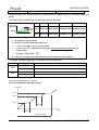
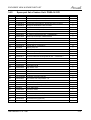
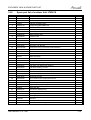
PNXA 9 DCI
PNXA 12 DCI
PNXA 18 DCI
PNXA 21 DCI
PNXA 24 DCI
GC 9 DCI
GC 12 DCI
YBD 018
YBD 022
YBD 024
REFRIGERANT
R410A
SM PNXADCI 1-A.1 GB
HEAT PUMP
APRIL – 2012
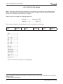
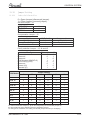
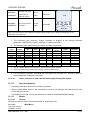
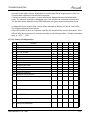
LIST OF EFFECTIVE PAGES
LIST OF EFFECTIVE PAGES
Note: Changes in the pages are indicated by a “Revision#” in the footer of each effected page
(when none indicates no changes in the relevant page). All pages in the following list represent
effected/ non effected pages divided by chapters.
Dates of issue for original and changed pages are:
Original ....... 0 ........September 2007
Updated .......01 ......
............April 2012
Total number of pages in this publication is 108 consisting of the following:
Page
No.
Revision
No. #
Page
No.
Revision
No. #
Page
No.
Revision
No. #
Title ....................... 1
A ........................... 1
i............................. 1
1-1 - 1-4 ................ 1
2-1 - 2-5................ 1
3-1 ........................ 1
4-1 - 4-3 ................ 1
5-1 - 5-9 ................ 1
6-1 - 6-5 ................ 1
7-1 ........................ 1
8-1-8-3 .................. 1
9-1-9-2 .................. 1
10-1-10-2 .............. 1
11-1-11-16............. 1
12-1-12-13 ............ 1
13-1-13-3 . ............ 1
14-1-14-13 ............ 1
15-1 ...................... 1
Appendix -A ...........1
Ɣ Zero in this column indicates an original page.
*Due to constant improvements please note that theGDWDRQWKLVVHUYLFHPDQXDOFDQEHPRGL¿HG
with out notice.
**Photos are not contractual
A
SM PNXADCI 1-A.1 GB
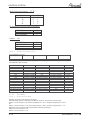
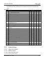
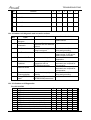
TABLE OF CONTENTS
Table of Contents
1.
INTRODUCTION ...................................................................................................1-1
2.
PRODUCT DATA SHEET ......................................................................................2-1
3.
RATING CONDITIONS ..........................................................................................3-1
4.
OUTLINE DIMENSIONS .......................................................................................4-1
5.
PERFORMANCE DATA & PRESSURE CURVES ...............................................5-1
6.
SOUND LEVEL CHARACTERISTICS ..................................................................6-1
7.
ELECTRICAL DATA..............................................................................................7-1
8.
WIRING DIAGRAMS .............................................................................................8-1
9.
REFRIGERATION DIAGRAMS .............................................................................9-1
10. ELECTRICAL CONNECTIONS.............................................................................10-1
11.
CONTROL SYSTEM PNXA9, PNXA12.................................................................11-1
12. CONTROL SYSTEM PNXA18, PNXA21, PNXA24...............................................12-1
13. TROUBLESHOOTING ..........................................................................................13-1
14. EXPLODED VIEWS AND SPARE PARTS LISTS.................................................14-1
15. TUBING CONNECTIONS......................................................................................15-1
16. APPENDIX A .........................................................................................................16-1
SM PNXADCI 1-A.1 GB
i
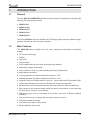
INTRODUCTION
1.
INTRODUCTION
1.1
General
The new PNX DCI INVERTER split wall mounted range has expanded, comprising the
following RC (heat pump) models:
Ɣ PNXA 9 DCI
Ɣ PNXA 12 DCI
Ɣ PNXA 18 DCI
Ɣ PNXA 21 DCI
Ɣ PNXA 24 DCI
The indoor PNX DCI units are available as LED display types, featuring esthetic design,
compact dimensions, and low noise operation.
1.2
Main Features
The PNXA DCI series EHQH¿WV from the most advanced technological innovations,
namely:
Ɣ DC inverter technology.
Ɣ R410A.
Ɣ High COP.
Ɣ Lego concept.
Ɣ Pre-Charged units up to the max’ allowing tubing distance.
Ɣ Networking system connectivity.
Ɣ AGU\FRQWDFWIRUFORFNRUSRZHUVKHGGLQJIXQFWLRQVFRQ¿JXUDEOH).
Ɣ Base heater connection.
Ɣ Cooling operation at outdoor temperature down to -10°C.
Ɣ Heating operation at outdoor temperature down to -15°C.
Ɣ Supports Indoor Air Quality features, such as – Ionizer and Active Electrostatic Filter.
Ɣ ,QGRRUODUJHGLDPHWHUFURVVÀRZIDQ, allowing low noise level operation.
Ɣ Bended indoor coil with treated alumiQXP¿QVDQGFRDWLQJIRULPSURYHGHI¿FLHQFy.
Ɣ Easy access to the interconnecting tubing and wiring connections, so that removing
the front grill or casing is not necessary.
Ɣ Refrigerant pipes can be connected to the indoor unit from 5 different optional
directions.
Ɣ Water condensate tray is equipped with two optional drain connections
Ɣ Automatic treated air sweep.
Ɣ Low indoor and outdoor noise levels.
Ɣ Easy installation and service.
SM PNXADCI 1-A.1 GB
1-1
INTRODUCTION
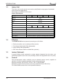
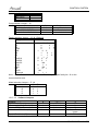
1.3
Indoor Unit
The indoor unit is wall mounted, and cDQEHHDVLO\¿WWHGWRPDQ\W\SHVRIUHVLGHQWLDO
DQGFRPPHUFLDOVDSSOLFDWLRQV
New design is available in LED version.
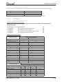
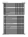
Indoor Unit features:
Feature
PNXA 9
PNXA 12
31;$
DisSlay
LED
Ionizer
OStional
ESF
OStional
Freshe aire
OStional
Indoor Ian motor
PG
PG
PG
+orizontal motorized louver
1.4
PG
31;$
DCI
Yes
Vertical motorized louver
OStional
+eating element
No
M2L Cable Sort
Yes
Dry contact
PNXA 21
Presence detector or (jumSer selected) Sower shedding
Filtration
The PNXA DCI INVVHULHVSUHVHQWVVHYHUDOW\SHVRIDLU¿OWHUV
Ɣ (DVLO\DFFHVVLEOHDQGUHXVDEOHSUH¿lters (mesh)
Ɣ 3UHFKDUJHGHOHFWURVWDWLF¿OWHUGLVSosable)
Ɣ $FWLYHFDUERQ¿OWHUGLVSRVDEOH
Ɣ ESF. $FWLYH(OHFWUR6WDWLFUHXVDEOH¿OWHURSWLRQDO
1.5
Ionizer (Optional)
A VSHFLDO design Ionizer SURWHFWHG by unique SDWHQWV integrated into the indoor unit,
generating negative ions to the room SroYLGLQJFRPIRUWDQGXSJUDGHGLQGRRUDLUTXDOLWy.
1.6
Control
The PLFURSURFHVVRU indoor controller, and an LQIUDUHG remote control, VXSSOLHG as
VWDQGDUGSURYLGHVFRPSOHWHRSHUDWLQJ IXQFWLRQDQGSURJUDPPLQJ
5HPRWHFRQWUROOHUV5&5&L5&L5&:%06
Networking system $LUFRQHWYHUVLRQ.DQGXS0,86:YHUVLRQ+DQGXS
)RUIXUWKHUGHWDLOVSOHDVHUHIHUWRWKH2SHUDWLRQDO0DQXDO
1-2
SM PNXADCI 1-A.1 GB
INTRODUCTION
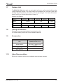
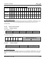
1.7
Outdoor Unit
The PNXA DC INVoutdoor units can be installed as ÀRRU or wall mounted units by using
a wall supporting bracket. The metal sheets are protected from corrosion paint work
allowing long life resistance. All outdoor units are pre-charged. For further information
please refer to the Product Data Sheet, Chapter 2.
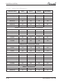
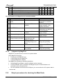
Outdoor Unit Feature
Feature
GC 9 DCI
Display
GC 12 DCI
3 LED's
Outdoor Fan
YBD 022
HMI
Base Heater
1.8
YBD 018
YBD 024
3 LED's
Optional
DCI
DCI
Triac
Triac
DCI
Tubing Connections
Flare type interconnecting tubing to be produced on site.
For further details please refer to the Installation Manual.
1.9
Accessories
Item
Description
MIU
MODBUS interface unit
RS485 Adapter
To be used as an interface
with RCW or μBMS remote
controllers
Base Heater
M2L cable Port
1.10
Inbox Documentation
Each unit is supplied with its own installation and operation manuals.
SM PNXADCI 1-A.1 GB
1-3
INTRODUCTION
1.11
Matching Table
1.11.1
R410A
INDOOR UNITS
OUTDOOR UNITS
1-4
MODEL
REFR”
PNXA 9
GC 9 DCI
R410A
¥
GC 12 DCI
R410A
YBD 018
R410A
YBD 022
R410A
YBD 024
R410A
PNXA 12
PNXA 18
PNXA 21
PNXA 24
¥
¥
¥
¥
SM PNXADCI 1-A.1 GB
PRODUCT DATA SHEET
2.
PRODUCT DATA SHEET
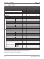
2.1
PNXA 9 DCI
Model Indoor Unit
Model Outdoor Unit
PNXA 9 DCI
GC 9 DCI R410A
Installation Method of Pipe
Characteristics
Capacity
Flared
Units
Btu/hr
kW
kW
W/W
(1)
Power input (1)
EER (Cooling) or COP(Heating) (1)
(QHUJ\HI¿FLHQF\FODVV
Power supply
OUTDOOR
INDOOR
Rated current
Power factor
Prated (IDU)
Prated (IDU+ODU)
Starting current
Circuit breaker rating
Fan type & quantity
Fan speeds
$LUÀRZ(2)
([WHUQDOVWDWLFSUHVVXUH
Sound power level (3)
Sound pressure level (4)
Moisture removal
Condenstate drain tube I.D
Dimensions
Net Weight
Package dimensions
Packaged weight
Units per pallet
Stacking height
Refrigerant control
Compressor type,model
Fan type & quantity
Fan speeds
$LUÀRZ
Sound power level
Sound pressure level (4)
Dimensions
Net Weight
Package dimensions
Packaged weight
Units per pallet
Stacking height
Refrigerant type
Standard charge
Additional charge
H/M/L
H/M/L
Min
H/M/L
H/M/L
:[+[D
:[+[D
H
H
H
H
:[+[D
:[+[D
Liquid line
Suction line
Connections between units 0D[WXELQJOHQJWh
0D[KHLJKW
difference
Operation control type
Heating elements (Option)
Others
(1)
(2)
(3)
(4)
Cooling
8530(4780-12280)
2.5(1.4-3.6)
0.50(0.42-1.0)
5.00
A
Heating
10240(5120-17060)
3.0(1.5-5.0)
0.60(0.39-1.6)
5.00
A
V
220-240
Ph
1
Hz
50
A
2.2
2.7
0.97
0.97
W
32
W
1600
A
10.5
A
15
&URVVÀRZ[
RPM
1050/900/800
m3/hr
530/430/330
Pa
0
dB(A)
51/ - /39
dB(A)
39/ - /26
l/hr
1
mm
16
mm
[[
kg
11.5
mm
[[
kg
14
units
28
units
7 levels
(OHFWURQLFDO([SDQVLRQValve
Single Rotary DC Inverter,Panasonic 5RS102XAB
3URSHOOHU[
RPM
830
m3/hr
1780
dB(A)
61
dB(A)
51
mm
[[
kg
38
mm
[[
kg
42
Units
9
units
3 levels
R410A
kg(7.5m)
1.1
No need
In.(mm)
1/4"(6.35)
In.(mm)
3/8"(9.53)
m.
0D[
0D[
m.
Remote control
kW
Rating conditions in accordance with ISO 5151 and ISO 13253 (for ducted units) and EN 14511.
$LUÀRZLQGXFWHGXQLWVDWQRPLQDOH[WHUQDOVWDWLFSUHVVXUH
Sound power in ducted units is measured at air discharge.
Sound pressure level measured at 1 meter distance from unit.
SM PNXADCI 1-A.1 GB
2-1
PRODUCT DATA SHEET
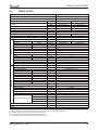
2.2
PNXA 12 DCI
Model Indoor Unit
Model Outdoor Unit
PNXA 12 DCI
GC 12 DCI R410A
Installation Method of Pipe
Characteristics
Units
Btu/hr
kW
kW
W/W
Capacity (1)
Power input (1)
EER (Cooling) or COP (Heating) (1)
(QHUJ\HI¿FLHQF\FODVV
V
Ph
Hz
A
Power supply
INDOOR
Rated current
Power factor
Prated (IDU)
Prated (IDU+ODU)
Starting current
Circuit breaker rating
Fan type & quantity
Fan speeds
$LUÀRZ(2)
([WHUQDOVWDWLFSUHVVXUH
Sound power level (3)
Sound pressure level (4)
Moisture removal
Condenstate drain tube I.D
Dimensions
Net Weight
Package dimensions
Packaged weight
Units per pallet
Stacking height
Refrigerant control
W
W
A
A
H/M/L
H/M/L
Min
H/M/L
H/M/L
:[+['
:[+['
RPM
m3/hr
Pa
dB(A)
dB(A)
l/hr
mm
mm
kg
mm
kg
units
units
OUTDOOR
Compressor type,model
Fan type & quantity
Fan speeds
$LUÀRZ
Sound power level
Sound pressure level (4)
Dimensions
Net Weight
Package dimensions
Packaged weight
Units per pallet
Stacking height
Refrigerant type
Standard charge
Additional charge
Single Rotary DC Inverter,Panasonic 5RS102XAB
H
H
H
H
:[+['
:[+['
Liquid line
Suction line
Connections between units
0D[WXELQJOHQJWh
0D[KHLJKW difference
Operation control type
Heating elements (Option)
Others
(1)
(2)
(3)
(4)
Flared
Cooling
Heating
11940(4780-14670)
13650(5100-19790)
3.5(1.4-4.3)
4.0(1.5-5.8)
0.87(0.42-1.25)
1.00(0.39-1.75)
4.02
4.00
A
A
220-240
1
50
3.9
4.5
0.97
0.97
40
1800
10.5
15
&URVVÀRZ[
1100/950/800
550/450/350
0
52/ - /39
40/ - /26
1.5
16
[[
11.5
[[
14
28
7 levels
(OHFWURQLFDO([SDQVLRQValve
RPM
m3/hr
dB(A)
dB(A)
mm
kg
mm
kg
Units
units
kg(7.5m)
g/m
In.(mm)
In.(mm)
m.
m.
3URSHOOHU[
830
1780
62
52
[[
38.5
[[
42.5
9
3 levels
R410A
1.2
No need
1/4"(6.35)
3/8"(9.53)
0D[
0D[
Remote control
kW
Rating conditions in accordance with ISO 5151 and ISO 13253 (for ducted units) and EN 14511.
$LUÀRZLQGXFWHGXQLWVDWQRPLQDOH[WHUQDOVWDWLFSUHVVXUH
Sound power in ducted units is measured at air discharge.
Sound pressure level measured at 1 meter distance from unit.
2-2
SM PNXADCI 1-A.1 GB
PRODUCT DATA SHEET
2.3
PNXA 18 DCI
Model Indoor Unit
Model Outdoor Unit
,QVWDOODWLRQ0HWKRGRI3LSH
Characteristics
&DSDFLW\(1)
OUTDOOR
INDOOR
3RZHULQSXW(1)
((5&RROLQJRU&23+HDWLQJ(1)
(QHUJ\HI¿FLHQF\FODVV
3RZHUVXSSO\
Rated current
Starting current
Circuit breaker rating
)DQW\SHTXDQWLW\
)DQVSHHGV
H/M/L
$LUÀRZ(2)
H/M/L
([WHUQDOVWDWLFSUHVVXUH
0LQ0D[
6RXQGSRZHUOHYHO(3)
H/M/L
6RXQGSUHVVXUHOHYHO(4)
H/M/L
0RLVWXUHUHPRYDO
Condenstate drain tube I.D
'LPHQVLRQV
:[+['
Weight
3DFNDJHGLPHQVLRQV
:[+['
Packaged weight
8QLWVSHUSDOOHW
Stacking height
5HIULJHUDQWFRQWURO
&RPSUHVVRUW\SHPRGHO
)DQW\SHTXDQWLW\
)DQVSHHGV
H/L
$LUÀRZ
H/L
6RXQGSRZHUOHYHO
H/L
6RXQGSUHVVXUHOHYHO(4)
H/L
'LPHQVLRQV
:[+['
Weight
3DFNDJHGLPHQVLRQV
:[+['
Packaged weight
8QLWVSHUSDOOHW
Stacking height
5HIULJHUDQWW\SH
5HIULJHUDQWFKDUJOHVVGLVWDQFH
$GGLWLRQDOFKDUJHSHUPHWHU
/LTXLGOLQH
6XFWLRQOLQH
Connections between units
0D[WXELQJOHQJWK
0D[KHLJKWGLfference
2SHUDWLRQFRQWUROW\SH
+HDWLQJHOHPHQWV
Others
(1)
(2)
(3)
(4)
PNXA 18 DCI
YBD 018
Units
Btu/hr
kW
kW
W/W
V/Ph/Hz
A
A
A
RPM
PKU
Pa
dB(A)
dB(A)
OKU
PP
PP
kg
PP
kg
units
units
RPM
PKU
dB(A)
dB(A)
PP
kg
PP
kg
Units
units
NJP
JP
,QPP
,QPP
P
P
)ODUHG
Cooling
Heating
17060(5120-20470) 19110(4440-23200)
5.00(1.50-6.00)
5.60(1.30-6.80)
1.37(0.40-2.00)
1.46(0.35-2.00)
3.65
3.84
A
A
96LQJOH+]
6.1
6.5
10.5
20
&URVVÀRZ[
1200/1050/900
850/760/620
0
55/51/47
43/39/34
2
16
[[
15
1[[
18
XQLWVSHUSDOOHW
OHYHOV
EEV
5RWDU\3DQDVRQLF56=$'
3URSHOOHUGLUHFW[
910
2160
63
53
[[
38
[[
41
XQLWVSHUSDOOHW
OHYHOV
R410A
1.26/7.5
No need
1/4”(6.35)
1/2”(12.7)
0D[
0D[
5HPRWHFRQWURO
kW
Rating conditions in accordance with ISO 5151 and ISO 13253 (for ducted units) and EN 14511.
$LUÀRZLQGXFWHGXQLWVDWQRPLQDOH[WHUQDOVWDWLFSUHVVXUH
6RXQGSRZHULQGXFWHGXQLWVLVPHDVXUHGDWDLUGLVFKDUJH
6RXQGSUHVVXUHOHYHOPHDVXUHGDWPHWHUGLVWDQFHIURPXQLW
SM PNXADCI 1-A.1 GB
2-3
PRODUCT DATA SHEET
2.4
PNXA 21 DCI
Model Indoor Unit
Model Outdoor Unit
PNXA 21 DCI
YBD 022
Installation Method of Pipe
Characteristics
Flared
Units
OUTDOOR
INDOOR
Power input (1)
EER (Cooling) or COP(Heating) (1)
(QHUJ\HI¿FLHQF\FODVV
Power supply
Rated current
Starting current
Circuit breaker rating
Fan type & quantity
Fan speeds
$LUÀRZ(2)
([WHUQDOVWDWLFSUHVVXUH
Sound power level (3)
Sound pressure level(4)
Moisture removal
Condenstate drain tube I.D
Dimensions
Weight
Package dimensions
Packaged weight
Units per pallet
Stacking height
Refrigerant control
Compressor type,model
Fan type & quantity
Fan speeds
$LUÀRZ
Sound power level
Sound pressure level(4)
Dimensions
Weight
Package dimensions
Packaged weight
Units per pallet
Stacking height
Refrigerant type
Refrigerant chargless distance
Additional charge per 1 meter
Operation control type
Heating elements
Others
(1)
(2)
(3)
(4)
m.
0D[
m.
0D[
kW
kW
W/W
V/Ph/Hz
A
A
A
H/M/L
H/M/L
0LQ0D[
H/M/L
H/M/L
W[H[D
:[+[D
H/L
H/L
H/L
H/L
:[+['
:[+['
Liquid line
Suction line
Connections between units
kg/m
g/m
In.(mm)
In.(mm)
Heating
21500(546020470(6140-23200)
26950)
6.00(1.80-6.80)
6.30(1.60-7.90)
1.82(0.50-2.40)
1.74(0.50-2.40)
3.30
3.62
A
A
220-240V/Single/50Hz
8.2
7.8
15
20
&URVVÀRZ[
1250/1100/1000
900/760/620
0
56/53/48
45/40/34
2.4
16
1060[295[210
15
1[[
18
16 units per pallet
8 levels
EEV
Two Rotary,GMCC DA150S1C-20FZ
3URSHOOHUGLUHFW[
800
2860
66
56
[[
45
[[
49
9 units per pallet
3 levels
R410A
1.60/7.5
No need
1/4”(6.35)
1/2”(12.7)
Btu/hr
Capacity (1)
0D[WXELQJOHQJWh
0D[KHLJKW
difference
RPM
m3/hr
Pa
dB(A)
dB(A)
l/hr
mm
mm
kg
mm
kg
units
units
RPM
m3/hr
dB(A)
dB(A)
mm
kg
mm
kg
Units
units
Cooling
Remote control
kW
Rating conditions in accordance with ISO 5151 and ISO 13253 (for ducted units) and EN 14511.
$LUÀRZLQGXFWHGXQLWVDWQRPLQDOH[WHUQDOVWDWLFSUHVVXUH
Sound power in ducted units is measured at air discharge.
Sound pressure level measured at 1 meter distance from unit.
2-4
SM PNXADCI 1-A.1 GB
PRODUCT DATA SHEET
2.5
PNXA 24 DCI
Model Indoor Unit
Model Outdoor Unit
PNXA 24 DCI
YBD 024
Installation Method of Pipe
Characteristics
Capacity (1)
OUTDOOR
INDOOR
Power input (1)
EER (Cooling) or COP(Heating) (1)
(QHUJ\HI¿FLHQF\FODVV
Power supply
Rated current
Starting current
Circuit breaker rating
Fan type & quantity
Fan speeds
H/M/L
$LUÀRZ(2)
H/M/L
([WHUQDOVWDWLFSUHVVXUH
0LQ0D[
Sound power level (3)
H/M/L
Sound pressure level (4 )
H/M/L
Moisture removal
Condenstate drain tube I.D
Dimensions
:[+['
Weight
Package dimensions
:[+['
Packaged weight
Units per pallet
Stacking height
Refrigerant control
Compressor type,model
Fan type & quantity
Fan speeds
H/L
$LUÀRZ
H/L
Sound power level
H/L
Sound pressure level (4)
H/L
Dimensions
:[+['
Weight
Package dimensions
:[+['
Packaged weight
Units per pallet
Stacking height
Refrigerant type
Refrigerant chargless distance
Additional charge per 1 meter
Liquid line
Suction line
Connections between units 0D[WXELQJOHQJWh
0D[KHLJKWGLfference
Operation control type
Heating elements (Option)
Others
(1)
(2)
(3)
(4)
kg/m
g/m
In.(mm)
In.(mm)
m.
Flared
Cooling
Heating
23188(5100~25575)
25916(5100~30000)
6.8(1.5-7.5)
7.6(1.5~8.8)
2.25(0.5-2.8)
2.35(0.45~3.0)
3.01
3.23
B
C
220-240V/Single/50Hz
10
10.5
15
20
&URVVÀRZ[
1300/1150/1000
1350/1200/1050
950/800/650
1000/850/700
0
60/56/51
47/43/38
2.5
16
[[
15
11[[
18
16
8 levels
EEV
Two Rotary, SANYO C-7RZ233H1A
3URSHOOHUGLUHFW[
850
3600
66
56
[[
64.5
[[
72
4
2 levels
R410A
2.3kg/30m
No Need
3/8"(9.53)
5/8"(15.88)
0D[
m.
0D[
Units
Btu/hr
kW
kW
W/W
V/Ph/Hz
A
A
A
RPM
m3/hr
Pa
dB(A)
dB(A)
l/hr
mm
mm
kg
mm
kg
units
units
RPM
m3/hr
dB(A)
dB(A)
mm
kg
mm
kg
Units
units
Remote control
kW
Rating conditions in accordance with ISO 5151 and ISO 13253 (for ducted units) and EN 14511.
$LUÀRZLQGXFWHGXQLWVDWQRPLQDOH[WHUQDOVWDWLFSUHVVXUH
Sound power in ducted units is measured at air discharge.
Sound pressure level measured at 1 meter distance from unit.
SM PNXADCI 1-A.1 GB
2-5
RATING CONDITIONS
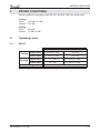
3.
RATING CONDITIONS
Rating conditions in accordance with ISO 5151 and ISO 13253 (for ducted units).
Cooling:
Indoor:
27oC DB 19oC WB
Outdoor: 35 oC DB
Heating:
Indoor:
20oC DB
Outdoor: 7oC DB 6oC WB
3.1
Operating Limits
3.1.1
R410A
Indoor
Cooling
Heating
Upper limit
32oC DB 23oC WB
46oC DB
Lower limit
21oC DB 15oC WB
-10oC DB
Upper limit
27oC DB
24oC DB 18oC WB
Lower limit
10oC DB
-15oC DB -16oC WB
Voltage
SM PNXADCI 1-A.1 GB
Outdoor
198 – 264 V
3-1
OUTLINE DIMENSIONS
OUTLINE DIMENSIONS
4.1
Indoor Unit: PNXA 9 / 12 DCI
MOUNTING TEMPLATE
TO BE USED FOR LOCATION
OF INDOOR UNIT ON THE WALL
CEELING
18.5
810.0
MOUTING PLATE OUTLINE
30.0
167.5
167.5
100.0 MIN
4.
INDOOR UNIT OUTLINE
83.0
83.0
42.0
42.0
100.5
100.5
285.0
8.0
8.0
93.0
TUBING WALL OPENING
(FOR REAR ROUTING)
93.0
TUBING WALL OPENING
(FOR REAR LEFT ROUTING)
210
811
285
AIR INTAKE
AIR INTAKE
AIR OUTLET
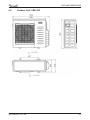
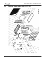
4.2
Outdoor Unit: GC 9 / 12 YBD 018
SM PNXADCI 1-A.1 GB
4-1
OUTLINE DIMENSIONS
Indoor Unit: PNXA 18 / 21 / 24
295
4.3
1060
4.4
4-2
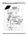
221
Outdoor Unit: YBD 022
SM PNXADCI 1-A.1 GB
OUTLINE DIMENSIONS
4.5
Outdoor Unit: YBD 024
SM PNXADCI 1-A.1 GB
4-3
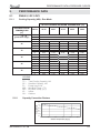
PERFORMANCE DATA & PRESSURE CURVES
5.
PERFORMANCE DATA
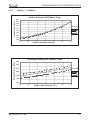
5.1
PNXA 9 / GC 9 DCI
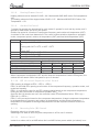
5.1.1
Cooling Capacity (kW) - Run Mode
ID COIL ENTERING AIR DB/WB TEMPERATURE [ºC]
OD COIL
ENTERING AIR DB
TEMPERATURE
[C0]
-10 - 20
(protection range)
25
30
35
40
46
DATA
22/15
24/17
27/19
29/21
32/23
TC
SC
PI
TC
SC
PI
TC
SC
PI
2.46
1.71
0.38
2.34
1.65
0.43
80 - 110 % of nominal
80 - 105 % of nominal
25 - 50 % of nominal
2.61
2.75
2.90
1.74
1.76
1.79
0.39
0.40
0.40
2.48
2.63
2.77
1.67
1.70
1.72
0.44
0.45
0.46
3.04
1.81
0.41
2.92
1.75
0.46
TC
SC
PI
2.21
1.58
0.48
2.36
1.60
0.49
2.50
1.63
0.50
2.65
1.66
0.51
2.79
1.68
0.52
TC
SC
PI
TC
SC
2.08
1.51
0.54
1.93
1.43
2.23
1.54
0.54
2.08
1.46
2.37
1.56
0.55
2.22
1.48
2.52
1.59
0.56
2.37
1.51
2.66
1.61
0.77
2.51
1.53
PI
0.60
0.61
0.62
0.62
0.63
LEGEND
TC –
SC –
PI –
WB –
DB –
ID –
OU -
Capacity Correction Factors
Capacity Ratio
5.1.2
Total Cooling Capacity, kW
Sensible Capacity, kW
Power Input, kW
Wet Bulb Temp., (oC)
Dry Bulb Temp., (oC)
Indoor
Outdoor
1. 2
1. 1
1
0.9
0. 8
0. 7
0.6
0. 5
20
25
30
35
40
45
Outdoor Temperature [deg C]
SM PNXADCI 1-A.1 GB
5-1
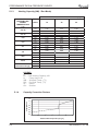
PERFORMANCE DATA & PRESSURE CURVES
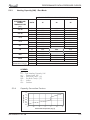
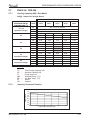
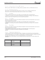
5.1.3
Heating Capacity (kW) - Run Mode)
ID COIL ENTERING AIR DB TEMPERATURE [ºC]
OD COIL
ENTERING AIR
DB/WB
TEMPERATURE
[ºC]
DATA
15
20
25
TC
PI
TC
PI
TC
PI
TC
PI
TC
PI
1.37
0.42
1.80
0.47
2.13
0.52
2.29
0.54
2.40
0.55
1.17
0.45
1.61
0.50
1.93
0.55
2.10
0.57
2.21
0.58
0.97
0.48
1.41
0.53
1.74
0.58
1.90
0.60
2.01
0.61
7/6
TC
PI
3.20
0.57
3.00
0.60
2.80
0.63
10/9
TC
PI
TC
PI
TC
PI
3.36
0.58
3.53
0.59
3.17
0.61
3.33
0.62
85 - 105 % of nominal
80 - 120 % of nominal
2.97
0.64
3.13
0.65
-15/-16
-10/-12
-7/-8
-1/-2
2/1
15/12
15-24
(Protection Range)
LEGEND
TC
TH – Total Heating Capacity, kW
PI – Power Input, kW
WB – Wet Bulb Temp., (oC)
DB – Dry Bulb Temp., (oC)
ID – Indoor
OU - Outdoor
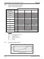
5.1.4
Capacity Correction Factors
Capacity Ratio
1.2
1.1
1
0.9
0.8
0.7
0.6
0.5
-15
-10
-5
0
5
10
15
Outdoor WB Temperature [deg C]
5-2
SM PNXADCI 1-A.1 GB
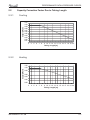
PERFORMANCE DATA & PRESSURE CURVES
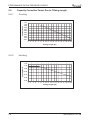
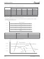
5.2
Cooling
Capacity Ratio
5.2.1
Capacity Correction Factor Due to Tubing Length
1.01
1.00
0.99
0.98
0.97
0.96
0.95
0.94
0.93
0.92
0.91
3
4
5
6
7
8
9 10 11 12 13 14 15 16 17 18 19 20
Tubing Length [m]
5.2.2
Heating
1.02
Capacity Ratio
1.00
0.98
0.96
0.94
0.92
0.90
3
4
5
6
7
8
9 10 11 12 13 14 15 16 17 18 19 20
Tubing Length [m]
SM PNXADCI 1-A.1 GB
5-3
PERFORMANCE DATA & PRESSURE CURVES
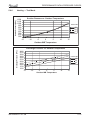
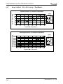
5.3
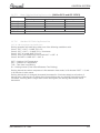
PNXA 12 / GC 12 DCI
5.3.1
Cooling Capacity (kW) - Run Mode
ID COIL ENTERING AIR DB/WB TEMPERATURE [ºC]
OD COIL
ENTERING AIR DB
TEMPERATURE
[ºC]
DATA
-10 - 20
(protection range)
25
30
35
40
46
22/15
24/17
27/19
29/21
32/23
TC
SC
PI
TC
SC
PI
TC
SC
PI
3.45
2.50
0.66
3.27
2.40
0.75
80 - 110 % of nominal
80 - 105 % of nominal
25 - 50 % of nominal
3.65
3.85
4.06
2.54
2.58
2.61
0.67
0.69
0.70
3.47
3.68
3.88
2.44
2.48
2.51
0.76
0.78
0.79
4.26
2.65
0.72
4.08
2.55
0.81
TC
SC
PI
3.09
2.31
0.84
3.30
2.34
0.86
3.50
2.38
0.87
3.70
2.42
0.88
3.91
2.45
0.90
TC
SC
PI
TC
SC
2.92
2.21
0.93
2.71
2.09
3.12
2.25
0.95
2.91
2.13
3.32
2.28
0.96
3.11
2.17
3.53
2.32
0.98
3.31
2.20
3.73
2.36
0.99
3.52
2.24
PI
1.04
1.06
1.07
1.09
1.10
LEGEND
TC –
SC –
PI –
WB –
DB –
ID –
OU -
Capacity Correction Factors
Capacity Ratio
5.3.2
Total Cooling Capacity, kW
Sensible Capacity, kW
Power Input, kW
Wet Bulb Temp., (oC)
Dry Bulb Temp., (oC)
Indoor
Outdoor
1.2
1.1
1
0.9
0.8
0.7
0.6
0.5
20
25
30
35
40
45
Outdoor Temperature [deg C]
5-4
SM PNXADCI 1-A.1 GB
PERFORMANCE DATA & PRESSURE CURVES
5.3.3
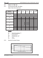
Heating Capacity (kW) - Run Mode
ID COIL ENTERING AIR DB TEMPERATURE [ºC]
OD COIL
ENTERING AIR
DB/WB
TEMPERATURE
[ºC]
DATA
15
20
25
TC
PI
TC
PI
TC
PI
TC
PI
TC
PI
1.82
0.70
2.40
0.79
2.84
0.86
3.06
0.89
3.20
0.92
1.56
0.75
2.14
0.84
2.58
0.91
2.80
0.94
2.94
0.97
1.30
0.80
1.88
0.89
2.32
0.96
2.53
0.99
2.68
1.02
7/6
TC
PI
4.26
0.95
4.00
1.00
3.74
1.05
10/9
TC
PI
TC
PI
TC
PI
4.48
0.97
4.70
0.99
4.42
1.02
4.44
1.04
85 - 105 % of nominal
80 - 120 % of nominal
3.96
1.07
4.18
1.09
-15/-16
-10/-12
-7/-8
-1/-2
2/1
15/12
15-24
(Protection Range)
LEGEND
TC
TH – Total Heating Capacity, kW
PI – Power Input, kW
WB – Wet Bulb Temp., (oC)
DB – Dry Bulb Temp., (oC)
ID – Indoor
OU - Outdoor
5.3.4
Capacity Correction Factors
Capacity Ratio
1.2
1.1
1
0.9
0.8
0.7
0.6
0.5
-15
-10
-5
0
5
10
15
Outdoor WB Temperature [deg C]
SM PNXADCI 1-A.1 GB
5-5
PERFORMANCE DATA & PRESSURE CURVES
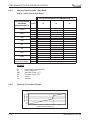
5.4
Cooling
Capacity Ratio
5.4.1
Capacity Correction Factor Due to TUbing Length
1.01
1.00
0.99
0.98
0.97
0.96
0.95
0.94
0.93
0.92
0.91
3
4
5
6
7
8
9 10 11 12 13 14 15 16 17 18 19 20
Tubing Length [m]
5.4.2
Heating
1.02
Capacity Ratio
1.00
0.98
0.96
0.94
0.92
0.90
3
4
5
6
7
8
9 10 11 12 13 14 15 16 17 18 19 20
Tubing Length [m]
5-6
SM PNXADCI 1-A.1 GB
PERFORMANCE DATA & PRESSURE CURVES
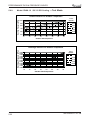
5.5
PNXA 18 / YBD 018
5.5.1
Cooling Capacity (kW) - Run Mode
230[V] : Indoor Fan at High Speed.
ID COIL ENTERING AIR DB/WB TEMPERATURE [0C]
OD COIL
ENTERING AIR DB
TEMPERATURE [0C]
DATA
TC
SC
PI
TC
SC
PI
TC
SC
PI
TC
SC
PI
TC
SC
PI
TC
SC
PI
-10 - 20
(protection range)
25
30
35
40
46
22/15
24/17
27/19
29/21
32/23
4.93
4.10
1.04
4.67
3.94
1.18
4.42
3.78
1.32
4.17
3.62
1.47
3.86
3.43
1.64
80 - 110 % of nominal
80 - 105 % of nominal
25 - 50 % of nominal
5.22
5.51
5.80
4.16
4.22
4.28
1.06
1.08
1.11
4.96
5.25
5.54
4.00
4.06
4.12
1.23
1.20
1.25
4.71
5.29
5.00
3.84
3.90
3.96
1.37
1.35
1.39
4.46
5.04
4.75
3.68
3.74
3.80
1.49
1.51
1.54
4.15
4.44
4.73
3.49
3.55
3.61
1.66
1.69
1.71
6.09
4.34
1.13
5.83
4.18
1.27
5.58
4.02
1.42
5.53
3.86
1.56
5.02
3.67
1.73
LEGEND
TC
SC
PI
WB
DB
ID
OD
5.5.2
–
–
–
–
–
–
–
Total Cooling Capacity, kW
Sensible Capacity, kW
Power Input, kW
Wet Bulb Temp., (oC)
Dry Bulb Temp., (oC)
Indoor
Outdoor
Capacity Correction Factors
Cooling Capacity Ratio Vs. Outdoor Temperature
Capacity Ration
1.20
1.10
1.00
0.90
0.80
0.70
0.60
0.50
20
25
30
35
40
45
Outdoor DB Temperature [ºC]
SM PNXADCI 1-A.1 GB
5-7
PERFORMANCE DATA & PRESSURE CURVES
5.5.3
Heating Capacity (kW) - Run Mode)
230[V] : Indoor Fan at High Speed.
ID COIL ENTERING AIR DB TEMPERATURE [0C]
OD COIL ENTERING
AIR DB/WB
TEMPERATURE [0C]
DATA
15
20
25
TC
PI
TC
PI
TC
PI
TC
PI
TC
PI
TC
PI
TC
PI
TC
PI
TC
PI
2.55
1.02
3.36
1.15
3.98
1.25
4.28
1.30
4.49
1.34
5.97
1.39
6.28
1.41
6.59
1.44
2.18
1.09
3.00
1.23
3.61
1.33
3.91
1.38
4.12
1.41
5.60
1.46
5.91
1.49
6.22
1.51
85 - 105 % of nominal
80 - 120 % of nominal
1.81
1.17
2.63
1.30
3.24
1.40
3.55
1.45
3.75
1.48
5.23
1.53
5.54
1.56
5.85
1.59
-15/-16
-10/-12
-7/-8
-1/-2
2/1
7/6
10/9
15/12
15-24
(Protection Range)
LEGEND
TC
PI
WB
DB
ID
OD
5.5.4
–
–
–
–
–
–
Total Heating Capacity, kW
Power Input, kW
Wet Bulb Temp., (oC)
Dry Bulb Temp., (oC)
Indoor
Outdoor
Capacity Correction Factors
Heating Capacity Ratio Vs. Outdoor Temperature
1.20
Capacity Ration
1.10
1.00
0.90
0.80
0.70
0.60
0.50
0.40
-15
-10
-5
0
5
10
15
Outdoor WB Temperature [ºC]
5-8
SM PNXADCI 1-A.1 GB
PERFORMANCE DATA & PRESSURE CURVES
5.6
PNXA 21 / YBD 022
5.6.1
Cooling Capacity (kW) - Run Mode
230[V] : Indoor Fan at High Speed.
ID COIL ENTERING AIR DB/WB TEMPERATURE [0C]
OD COIL
ENTERING AIR DB
TEMPERATURE [0C]
DATA
TC
SC
PI
TC
SC
PI
TC
SC
PI
TC
SC
PI
TC
SC
PI
TC
SC
PI
-10 - 20
(protection range)
25
30
35
40
(Protection Range)
46
(Protection Range)
22/15
24/17
27/19
29/21
32/23
5.91
4.64
1.38
5.61
4.46
1.57
5.30
4.28
1.76
5.00
4.10
1.95
4.64
3.88
2.18
80 - 110 % of nominal
80 - 105 % of nominal
25 - 50 % of nominal
6.26
6.61
6.95
4.71
4.78
4.85
1.41
1.44
1.47
5.96
6.30
6.65
4.53
4.60
4.67
1.63
1.60
1.66
5.65
6.35
6.00
4.35
4.42
4.49
1.82
1.79
1.85
5.35
6.05
5.70
4.17
4.24
4.31
1.98
2.01
2.04
4.99
5.33
5.68
3.95
4.02
4.09
2.21
2.24
2.27
7.30
4.92
1.50
7.00
4.74
1.69
6.70
4.56
1.88
6.39
4.38
2.07
6.03
4.16
2.30
LEGEND
TC
SC
PI
WB
DB
ID
OD
5.6.2
–
–
–
–
–
–
–
Total Cooling Capacity, kW
Sensible Capacity, kW
Power Input, kW
Wet Bulb Temp., (oC)
Dry Bulb Temp., (oC)
Indoor
Outdoor
Capacity Correction Factors
Cooling Capacity Ratio Vs. Outdoor Temperature
1.20
Capacity Ration
1.10
1.00
0.90
0.80
0.70
0.60
0.50
20
25
30
35
40
45
Outdoor DB Temperature [ºC]
SM PNXADCI 1-A.1 GB
5-9
PERFORMANCE DATA & PRESSURE CURVES
5.6.3
Heating Capacity (kW) - Run Mode
230[V] : Indoor Fan at High Speed.
ID COIL ENTERING AIR DB TEMPERATURE [0C]
OD COIL ENTERING
AIR DB/WB
TEMPERATURE [0C]
-15/-16
-10/-12
-7/-8
-1/-2
2/1
7/6
10/9
15/12
15-24
(Protection Range)
DATA
15
20
25
TC
PI
TC
PI
TC
PI
TC
PI
TC
PI
TC
PI
TC
PI
TC
PI
TC
PI
2.87
1.19
3.78
1.34
4.47
1.46
4.82
1.52
5.05
1.56
6.71
1.62
7.06
1.65
7.41
1.68
2.45
1.27
3.37
1.43
4.06
1.54
4.40
1.60
4.63
1.64
2.04
1.36
2.96
1.51
3.65
1.63
3.99
1.69
4.22
1.73
5.89
1.79
6.24
1.82
6.58
1.85
6.30
1.70
6.65
1.73
7.00
1.76
85 - 105 % of nominal
80 - 120 % of nominal
LEGEND
TC
PI
WB
DB
ID
OD
5.6.4
–
–
–
–
–
–
Total Heating Capacity, kW
Power Input, kW
Wet Bulb Temp., (oC)
Dry Bulb Temp., (oC)
Indoor
Outdoor
Capacity Correction Factors
Heating Capacity Ratio Vs. Outdoor Temperature
Capacity Ration
1.20
1.10
1.00
0.90
0.80
0.70
0.60
0.50
0.40
-15
-10
-5
0
5
10
15
Outdoor WB Temperature [ºC]
5-10
SM PNXADCI 1-A.1 GB
PERFORMANCE DATA & PRESSURE CURVES
5.7
PNXA 24 / YBD 024
5.7.1
Cooling Capacity (kW) - Run Mode
230[V] : Indoor Fan at High Speed.
ID COIL ENTERING AIR DB/WB TEMPERATURE [0C]
OD COIL
ENTERING AIR DB
TEMPERATURE [0C]
DATA
TC
80 - 110 % of nominal
-10 - 20
(protection range)
SC
80 - 105 % of nominal
PI
25 - 50 % of nominal
25
30
35
40
(Protection Range)
46
(Protection Range)
22/15
24/17
27/19
29/21
32/23
TC
6.70
7.09
7.49
7.88
8.28
SC
5.04
5.12
5.19
5.27
5.34
PI
1.70
1.74
1.78
1.82
1.85
TC
6.35
6.75
7.14
7.54
7.93
SC
4.85
4.92
5.00
5.07
5.15
PI
1.94
1.98
2.01
2.05
2.09
TC
6.01
6.41
6.80
7.19
7.59
SC
4.65
4.73
4.80
4.87
4.95
PI
2.17
2.21
2.25
2.29
2.33
TC
5.67
6.06
6.46
6.85
7.25
SC
4.45
4.53
4.60
4.68
4.75
PI
2.41
2.45
2.49
2.52
2.56
TC
5.26
5.65
6.04
6.44
6.83
SC
PI
4.22
4.29
4.37
4.44
4.52
2.69
2.73
2.77
2.81
2.85
LEGEND
TC
SC
PI
WB
DB
ID
OD
5.7.2
–
–
–
–
–
–
–
Total Cooling Capacity, kW
Sensible Capacity, kW
Power Input, kW
Wet Bulb Temp., (oC)
Dry Bulb Temp., (oC)
Indoor
Outdoor
Capacity Correction Factors
Cooling Capacity Ratio Vs. Outdoor Temperature
1.20
Capacity Ration
1.10
1.00
0.90
0.80
0.70
0.60
0.50
20
25
30
35
40
45
Outdoor DB Temperature [ºC]
SM PNXADCI 1-A.1 GB
5-11
PERFORMANCE DATA & PRESSURE CURVES
5.7.3
Heating Capacity (kW) - Run Mode
230[V] : Indoor Fan at High Speed.
ID COIL ENTERING AIR DB TEMPERATURE [0C]
OD COIL ENTERING
AIR DB/WB
TEMPERATURE [0C]
-15/-16
-10/-12
-7/-8
-1/-2
2/1
7/6
10/9
15/12
15-24
(Protection Range)
DATA
15
20
25
TC
3.46
2.96
2.46
PI
1.64
1.76
1.88
TC
4.57
4.07
3.57
PI
1.86
1.97
2.09
TC
5.40
4.90
4.40
PI
2.02
2.14
2.25
TC
5.81
5.31
4.81
PI
2.10
2.22
2.33
TC
6.09
5.59
5.09
PI
2.15
2.27
2.39
TC
8.10
7.60
7.10
PI
2.23
2.35
2.47
TC
8.52
8.02
7.52
PI
2.28
2.39
2.51
TC
8.94
8.44
7.94
PI
2.32
2.44
2.55
TC
PI
85 - 105 % of nominal
80 - 120 % of nominal
LEGEND
TC
PI
WB
DB
ID
OD
5.7.4
–
–
–
–
–
–
Total Heating Capacity, kW
Power Input, kW
Wet Bulb Temp., (oC)
Dry Bulb Temp., (oC)
Indoor
Outdoor
Capacity Correction Factors
Heating Capacity Ratio Vs. Outdoor Temperature
Capacity Ration
1.20
1.10
1.00
0.90
0.80
0.70
0.60
0.50
0.40
-15
-10
-5
0
5
10
15
Outdoor WB Temperature [ºC]
5-12
SM PNXADCI 1-A.1 GB
PERFORMANCE DATA & PRESSURE CURVES
5.8
Capacity Correction Factor Due to Tubing Length
5.8.1
Cooling
1.02
Capacity ratio
1.00
0.98
0.96
0.94
0.92
0.90
0.88
0.86
4
6
8
10
12
14
16
18
20
22
24
26
28
20
22
24
26
28
30
Tubing length(m)
Heating
Capacity ratio
5.8.2
1.02
1.00
0.98
0.96
0.94
0.92
0.90
0.88
0.86
0.84
4
6
8
10
12
14
16
18
30
Tubing Length(m)
SM PNXADCI 1-A.1 GB
5-13
PERFORMANCE DATA & PRESSURE CURVES
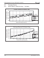
5.9
Pressure Curves
5.9.1.
Model: PNXA 18 / YBD 018 Cooling — Test Mode
Suction Pressure VS.Outdoor Temp.
Suction Pressure [kPa]
1100
1000
900
Indoor
DB/WB Tem p'
800
22/ 15
24/ 17
700
27/ 19
29/ 21
600
32/ 23
500
10
15
20
25
30
35
40
45
Outdoor DB Temperature[ºC ]
Discharge Pressure VS. Outdoor Temp.
Discharge Pressure [kPa]
4000
3500
Indoor
DB/WB Tem p'
3000
2500
22/ 15
2000
24/ 17
1500
29/ 21
27/ 19
32/ 23
1000
10
15
20
25
30
35
40
45
Outdoor DB Temperature[ºC ]
5-14
SM PNXADCI 1-A.1 GB
PERFORMANCE DATA & PRESSURE CURVES
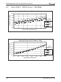
5.9.2.
Heating — Test Mode
Suction Pressure VS.Outdoor Temp.
Suction Pressure [kPa]
1100
1000
900
Indoor DB
800
700
15
20
600
25
500
400
300
200
-15
-10
-5
0
5
10
15
Outdoor WB Temperature[ºC ]
Discharge Pressure VS. Outdoor Temp.
Discharge Pressure [kPa]
4000
3500
Indoor DB
3000
15
2500
20
25
2000
1500
1000
-15
-10
-5
0
5
10
15
Outdoor WB Temperature
SM PNXADCI 1-A.1 GB
5-15
PERFORMANCE DATA & PRESSURE CURVES
Model: PNXA 21 / YBD 022 Cooling — Test Mode.
5.9.3
Suction Pressure VS.Outdoor Temp.
Suction Pressure [kPa]
1100
1000
900
Indoor
DB/WB Tem p'
800
22/ 15
24/ 17
700
27/ 19
29/ 21
600
32/ 23
500
10
15
20
25
30
35
40
45
Outdoor DB Temperature[ºC ]
Discharge Pressure [kPa]
Discharge Pressure VS. Outdoor Temp.
4000
3500
Indoor
DB/WB Tem p'
3000
2500
22/ 15
24/ 17
2000
27/ 19
29/ 21
1500
32/ 23
1000
10
15
20
25
30
35
40
45
Outdoor DB Temperature
5-16
SM PNXADCI 1-A.1 GB
PERFORMANCE DATA & PRESSURE CURVES
5.9.4
Heating — Test Mode
Suction Pressure VS.Outdoor Temp.
Suction Pressure [kPa]
1100
1000
900
800
Indoor DB
700
15
20
25
600
500
400
300
200
-15
-10
-5
0
5
10
15
Outdoor WB Temperature[ºC ]
Discharge Pressure VS. Outdoor Temp.
Discharge Pressure [kPa]
4000
3500
3000
Indoor DB
15
2500
20
25
2000
1500
1000
-15
-10
-5
0
5
10
15
Outdoor WB Temperature [ºC ]
SM PNXADCI 1-A.1 GB
5-17
PERFORMANCE DATA & PRESSURE CURVES
Model: PNXA 24 / YBD 024 Cooling — Test Mode.
5.9.5
Suction Pressure [kPa]
Suction Pressure vs. Outdoor Temperature
1000
Indoor
DB/WB
900
22/15
24/17
27/19
29/21
32/23
800
700
600
10
15
20
25
30
35
40
45
Outdoor DB Temperature
Discharge Pressure [kPa]
Discharge Pressure vs. Outdoor Temperature
Indoor
DB/WB
3750
3500
3250
3000
2750
2500
2250
2000
1750
1500
22/15
24/17
27/19
29/21
32/23
10
15
20
25
30
35
40
45
Outdoor DB Temperature
5-18
SM PNXADCI 1-A.1 GB
PERFORMANCE DATA & PRESSURE CURVES
5.9.6
Heating — Test Mode
Suction Pressure [kPa]
Suction Pressure vs. Outdoor Temperature
1200
1100
1000
900
800
700
600
500
400
300
Indoor DB
15
20
25
-15
-10
-5
0
5
10
15
Outdoor WB Temperature
Discharge Pressure [kPa]
Discharge Pressure vs. Outdoor Temperature
4000
3750
3500
3250
3000
2750
2500
2250
2000
1750
1500
Indoor DB
15
20
25
-15
SM PNXADCI 1-A.1 GB
-10
-5
0
5
Outdoor WB Temperature
10
15
5-19
PERFORMANCE DATA & PRESSURE CURVES
5.9.7
Model: PNXA 9 / GC 9 DCI Cooling —Test Mode.
Suction Pressure [kPa]
Suction Pressure vs. Outdoor Temperature
Indoor
DB/WB
22/15
1000
920
24/17
840
27/19
760
29/21
680
32/23
600
10
15
20
25
30
35
40
45
Outdoor DB Temperature
Discharge Pressure [kPa]
Discharge Pressure vs. Outdoor Temperature
Indoor
DB/WB
3700
3500
3300
3100
2900
2700
2500
2300
2100
1900
1700
1500
22/15
24/17
27/19
29/21
32/23
10
15
20
25
30
35
40
45
Outdoor DB Temperature
5-20
SM PNXADCI 1-A.1 GB
PERFORMANCE DATA & PRESSURE CURVES
5.9.8
Heating — Test Mode
Suction Pressure [kPa]
Suction Pressure vs. Outdoor Temperature
1050
950
850
750
650
550
450
350
250
Indoor DB
15
20
25
-15
-10
-5
0
5
10
15
Outdoor WB Temperature
Discharge Pressure [kPa]
Discharge Pressure vs. Outdoor Temperature
3400
3250
3100
2950
2800
2650
2500
2350
2200
2050
1900
1750
Indoor DB
15
20
25
-15
-10
-5
0
5
10
15
Outdoor WB Temperature
SM PNXADCI 1-A.1 GB
5-21
PERFORMANCE DATA & PRESSURE CURVES
5.9.9
Model: PNXA 12 / GC 12 DCI Cooling — Test Mode.
Suction Pressure [kPa]
Suction Pressure vs. Outdoor Temperature
Indoor
DB/WB
1000
22/15
920
24/17
840
27/19
760
29/21
680
32/23
600
10
15
20
25
30
35
40
45
Outdoor DB Temperature
Discharge Pressure [kPa]
Discharge Pressure vs. Outdoor Temperature
Indoor
DB/WB
3700
3500
3300
3100
2900
2700
2500
2300
2100
1900
1700
1500
22/15
24/17
27/19
29/21
32/23
10
15
20
25
30
35
40
45
Outdoor DB Temperature
5-22
SM PNXADCI 1-A.1 GB
PERFORMANCE DATA & PRESSURE CURVES
5.9.10
Heating — Test Mode
Suction Pressure [kPa]
Suction Pressure vs. Outdoor Temperature
1050
950
850
750
650
550
450
350
250
Indoor DB
15
20
25
-15
-10
-5
0
5
10
15
Outdoor WB Temperature
Discharge Pressure [kPa]
Discharge Pressure vs. Outdoor Temperature
3400
3250
3100
2950
2800
2650
2500
2350
2200
2050
1900
1750
Indoor DB
15
20
25
-15
-10
-5
0
5
10
15
Outdoor WB Temperature
SM PNXADCI 1-A.1 GB
5-23
SOUND LEVEL CHARACTERISTICS
6.
SOUND LEVEL CHARACTERISTICS
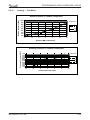
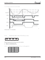
6.1
Sound Pressure Level
Unit
1m
Wall
0.8m
FAN SPEED
LINE
HI
Mic.
ME
LO
Figure 1
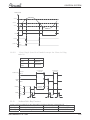
6.2
Sound Pressure Level Spectrum (Measured as Figure 1)
PNXA 12
-70NC
-60NC
-50NC
-40NC
-30NC
APPROXIMATE
THRESHOLD OF
HEARING FOR
CONTINUOUS
NOISE
-20NC
MICRO AR0. 02 dB re , OCT VE BAN S UN PRES URE L VEL
MICRO AR0. 02 dB re , OCT VE BAN S UN PRES URE L VEL
PNXA 9
-70NC
-60NC
-50NC
-40NC
-30NC
APPROXIMATE
THRESHOLD OF
HEARING FOR
CONTINUOUS
NOISE
Hz, AND CE TER FREQUENC ES
Hz, AND CE TER FREQUENC ES
PNXA 21
NC-70
NC-60
NC-50
NC-40
NC-30
NC-20
BAND CENTER FREQUENCIES, Hz
SM PNXADCI 1-A.1 GB
OCTAVE BAND SOUND PRESSURE LEVEL, dB re 0.002 MICRO BAR
OCTAVE BAND SOUND PRESSURE LEVEL, dB re 0.002 MICRO BAR
PNXA 18
APPROXIMATE
THRESHOLD OF
HEARING FOR
CONTINUOUS
NOISE
-20NC
NC-70
NC-60
NC-50
NC-40
NC-30
APPROXIMATE
THRESHOLD OF
HEARING FOR
CONTINUOUS
NOISE
NC-20
BAND CENTER FREQUENCIES, Hz
6-1
SOUND LEVEL CHARACTERISTICS
FLO 30
OCTAVE BAND SOUND PRESSURE LEVEL, dB re 0.002 MICRO BAR
PNXA 24
NC-70
NC-60
NC-50
NC-40
NC-30
APPROXIMATE
THRESHOLD OF
HEARING FOR
CONTINUOUS
NOISE
NC-20
BAND CENTER FREQUENCIES, Hz
6-2
SM PNXADCI 1-A.1 GB
SOUND LEVEL CHARACTERISTICS
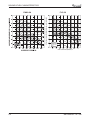
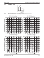
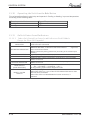
6.3
Outdoor units
Unit
1m
Mic.
Ground
Figure 2
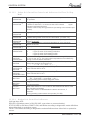
6.4
Sound Pressure Level Spectrum (Measured as Figure 2)
GC 9 DCI Cooling
GC 9 DCI Heating
GC 12 DCI Cooling
GC 12 DCI Heating
SM PNXADCI 1-A.1 GB
6-3
SOUND LEVEL CHARACTERISTICS
YBD 018 DCI Heating
NC-70
NC-60
NC-50
NC-40
NC-30
APPROXIMATE
THRESHOLD OF
HEARING FOR
CONTINUOUS
NOISE
NC-20
OCTAVE BAND SOUND PRESSURE LEVEL, dB re 0.002 MICRO BAR
OCTAVE BAND SOUND PRESSURE LEVEL, dB re 0.002 MICRO BAR
YBD 018 DCI Cooling
NC-70
NC-60
NC-50
NC-40
NC-30
APPROXIMATE
THRESHOLD OF
HEARING FOR
CONTINUOUS
NOISE
BAND CENTER FREQUENCIES, Hz
BAND CENTER FREQUENCIES, Hz
NC-70
NC-60
NC-50
NC-40
NC-30
NC-20
BAND CENTER FREQUENCIES, Hz
6-4
YBD 022 DCI Heating
OCTAVE BAND SOUND PRESSURE LEVEL, dB re 0.002 MICRO BAR
OCTAVE BAND SOUND PRESSURE LEVEL, dB re 0.002 MICRO BAR
YBD 022 DCI Cooling
APPROXIMATE
THRESHOLD OF
HEARING FOR
CONTINUOUS
NOISE
NC-20
NC-70
NC-60
NC-50
NC-40
NC-30
APPROXIMATE
THRESHOLD OF
HEARING FOR
CONTINUOUS
NOISE
NC-20
BAND CENTER FREQUENCIES, Hz
SM PNXADCI 1-A.1 GB
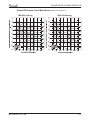
SOUND LEVEL CHARACTERISTICS
Sound Pressure Level Spectrum (Measured as Figure 2)
YBD 024 Cooling
SM PNXADCI 1-A.1 GB
YBD 024 Heating
6-5
ELECTRICAL DATA
7.
ELECTRICAL DATA
7.1
Single Phase Unit
Model
Power Supply
Connected to
Maximum Current
Inrush Current \(a)
Starting Current\(b)
Circuit Breaker
Power Supply
Interconnecting cable
PNXA 9 DCI PNXA 12 DCI PNXA 18 DCI PNXA 21 DCI PNXA 24 DCI
10A
35A
10A
16A
3 X 1.5 mm²
4 X 1.5 mm²
1 PH ,220-240VAC ,50HZ
To indoor
13.5A
15A
45 A
13.5 A
15A
20 A
3 X 2.5 mm²
4 X 2.5 mm²
To outdoor
15.7A
<35A
15.7A
(a) Inrush current is the current when power is up (charging the DC capacitors
at outdoor unit controller).
(b) Starting current is the current at compressor start up.
NOTE
Power wiring cord should comply with local lows and electrical
regulations requirements.
SM PNXADCI 1-A.1 GB
7-1
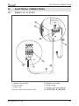
RED
V W
BLK
1 2
P102
REVERSE
VALVE
1 2
P103
BASE
HEATER
(OPTIONAL)
P101
N L COM
BLUE
BROWN
RED
Y/G
P105
EARTH
FERRITE CORE
FUSE
OFAN
1 2 1 2 1 2 1 2
P604 P603 P602 P606
OAT CTT OCT HST
N/3
L/4
C/5
EEV
P605
6 5 4 3 2 1
1 2 3 4 5 6
P301
JP602
1 2 3 4 5 6
ODU CONTROLLER PCBA
P501P502 P503
U
BRN
COMP
GND
VCC
VSP
FG
SM PNXADCI 1-A.1 GB
VDC
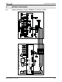
OUTDOOR UNIT CIRCUIT DIAGRAM
WIRING DIAGRAMS
8.
WIRING DIAGRAMS
8.1
Indoor & Outdoor Units: PNXA 9, 12 / GC 9, 12 DCI
8-1
WIRING DIAGRAMS
Indoor Unit: PNXA 18 / PNXA 22 DCI
Horizontal step motor Vertical step motor
RAT ICT
Fresh Ai r
P16
P11P15P19P14P3
12
12
P4( red) P5(white)
1
1 2
P2
M1
ESF
Ionizer
power out
2uF 450V
red
brown
gray
blue
black
white
gray
capacitor
Ionizer
M
1 23 4 56
M2
Dry contact
(clock)
IFAN
ESF
power out
8.2
2
P12
P8( Red)
12 3
5
P6(White)
14 2 3 4 5
12
P10(Red)
P1
Indoor unit controller PCB
P22
P9
P20 P13
Jumper
megatool
P7 1 2 3 4
PH-12
1 7 8 9 10 P24
magnetic ring
To metal sheet
Display
6 5/C 4/L
L
Note: The dashed part is optional
Y/G
Y/G
Red
8.3
Brown
Brown
Blue
Blue
Power supply
~230V50Hz
Outdoor Unit: YBD 018 / YBD 022
U V W
P503 P501 P201 P202
P502
FUSE
1 2
P109
P104 P105
P804 P803
P106
P101
P107
BLACK
BLUE
BROWN
P102 P103
L N C
YELLOW/GREEN
1 2
P108
P602
HST OCT
CN801
P601
ON
DIP
1 2 3 4
TO
DMSMP
CTT OAT OMT
BLUE
BLOACK
RED
BH
BLUE
WHITE
BLACK
BROWN
RED
YEL
CAP GRN
MODEL
SETTING
P801
1 23 4
P802
P805
6 5 4 3 2 1
M2L
C
N
L
TO
IDU
TO AC MAINS
(FOR POWER SOURCE FROM ODU)
8-2
SM PNXADCI 1-A.1 GB
WIRING DIAGRAMS
P402
WHITE
COMP
BK
RD
WH
RD
BN
OFAN
P604
P603
P602
BU
EEV
BLUE
BLUE
BLUE
P401
P804 P802 P803 P801
1 2 3 4 5 6 7 8 9 10 2 1 3 2 1 2 1 4 3 2 1
CN601
P601
654321 54321 W V U U V W
MODEL_SET
ODU MODEL SETTING
1 2 3 4
ODU0
CN801
2 4 6 8 101214
1 3 5 7 9 1113
FLASH_PORT
DIP
ODU2
ODU1
ON
ODU3
SELF
TEST
N L
P201 P202
P101
P503
P502
P501
P103
ODU0 ODU1 ODU2 ODU3 ODU MODEL
OFF OFF OFF OFF P(DCI80)
P104
RV
BROWN
BROWN
P106
P104
P103
P105
COM
LI
NI
L0
N0
P108
P107
P102
RED
CCH
CN802
ODU
P404
P405
P406
3 2 1 4 3 2 1
P106
P105
FUSE
WHITE
M2L
P403
STANDBY PWR-SHED FORCED ALARM
MSMP
-PWR
FB
Indoor & Outdoor Units: PNXA 24 DCI / YBD 024
TO AC MAINS (FOR POWER
SOURCE FROM ODU)
8.4
P701
4 3 2 1
AUX
HMI
NIGHT
HST CTT OCT OAT OMT
SM PNXADCI 1-A.1 GB
8-3
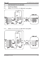
REFRIGERATION DIAGRAMS
9.
REFRIGERATION DIAGRAMS
9.1
Heat Pump Models
9.1.1
PNXA 9, 12, 18, 21 / GC 9, 12, YBD018/022 Cooling Mode
EEV
9.1.2
PNXA 9, 12, 18, 21 / GC 9, 12, YBD 018/22 Heating Mode
EEV
SM PNXADCI 1-A.1 GB
9-1
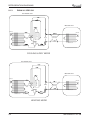
REFRIGERATION DIAGRAMS
9.1.3
PNXA 24 / YBD 024
OUTDOOR UNIT
INDOOR UNIT
Sensor
Compressor
Sensor
Reverse
valve
Valves
Flared
connection
Indoor coil
EEV
Outdoor coil
Strainer
Strainer
COOLING & DRY MODE
OUTDOOR UNIT
INDOOR UNIT
Sensor
Compressor
Sensor
Reverse
valve
Valves
Indoor coil
EEV
Outdoor coil
Strainer
Flared
connection
Strainer
HEATING MODE
9-2
SM PNXADCI 1-A.1 GB
ELECTRICAL CONNECTIONS
10.
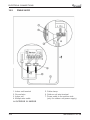
ELECTRICAL CONNECTIONS
10.1
PNXA 9, 12, 18, 21 DCI
1
ESF-PWR
3
COOL
ESF-EN
HEAT
RESET
MODE
5/C 4/L N L
2
4
N
4/L 5/C
7
A
B
6
5
1. Indoor unit terminal
2. Ground wire.
3. Indoor coil.
4.Power cable in the indoor side.
SM PNXADCI 1-A.1 GB
5. Multiple wire cable.
6. Cable clamp.
7. Outdoor unit wire terminal.
A. OUTDOOR B. INDOOR
10-1
ELECTRICAL CONNECTIONS
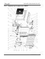
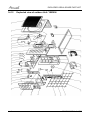
10.2
PNXA 24 DCI
1. Indoor unit terminal
2. Ground wire.
3. Indoor coil.
4. Multiple wire cable.
A. OUTDOOR B. INDOOR
10-2
5. Cable clamp.
6. Outdoor unit wire terminal.
7. Power cable in the outdoor side
(only for outdoor unit power supply)
SM PNXADCI 1-A.1 GB
CONTROL SYSTEM
11.
CONTROL SYSTEM for PNXA 9 / 12
11.1
General Functions and Operating Rules
The DCI software is fully parametric.
All the model dependent parameters are shown in Blue color and with Italic style [parameter].
The parameters values are given in the last section of this control logic chapter of the service
manual.
11.1.1
System Operation Concept
The control function is divided between indoor and outdoor unit controllers. Indoor unit is the
System ‘Master’, requesting the outdoor unit for cooling/heating capacity supply. The outdoor unit is
the system 'Slave’ and it must supply the required capacity nless it enters into a protection mode
avoiding it from supplying the requested capacity.
The capacity request is transferred via indoor to outdoor communication, and is represented by a
parameter called ‘NLOAD’. NLOAD is an integer number with values between 0 and 127, and it
represents the heat or cool load felt by the indoor unit.
11.1.2
Compressor Frequency Control
11.1.2.1 NLOAD setting
The NLOAD setting is done by the indoor unit controller, based on a PI control scheme.
The actual NLOAD to be sent to the outdoor unit controller is based on the preliminary LOAD
calculation, the indoor fan speed, and the power shedding function.
NLOAD limits as a function of indoor fan speed:
Indoor Fan Speed Maximum NLOAD Cooling
Low
Max NLOADIF1C
Medium
Max NLOADIF2C
High
Max NLOADIF3C
Turbo
Max NLOADIF4C
Auto
Max NLOADIF5C
Maximum NLOAD Heating
127
127
127
127
127
NLOAD limits as a function of power shedding:
Mode
Power Shedding OFF
Cool
No limit
Heat
No limit
Power Shedding ON
Nominal Cooling
Nominal Heating
11.1.3
Target Frequency Setting
The compressor target frequency is a function of the NLOAD number sent from the indoor
controller and the outdoor air temperature.
Basic Target Frequency Setting:
NLOAD
127
10 < NLOAD < 127
10
0
Target Frequency
Maximum frequency
Interpolated value between minimum and maximum frequency
Minimum frequency
Compressor is stopped
SM PNXADCI 1-A.1 GB
11-1
CONTROL SYSTEM
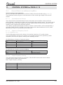
Target frequency limits as a function of outdoor air temperature )OAT(:
OAT Range
Cool mode limits
Heat mode limits
OAT < 6
No limit
MaxFreqAsOATC
OAT < 15
MaxFreqAsOAT1H
15 OAT < 24
MaxFreqAsOAT2H
24 OAT
No limit
11.1.4
Frequency Changes Control
Frequency change rate is 1 Hz/sec.
11.1.5
Compressor Starting Control
Frequency
Step 3
Step 2
Step 1
1
Minute
1
Minute
Time
Min 10 Minutes
11.1.6
Minimum On and Off Time
3 minutes.
11.1.7
Indoor Fan Control
10 Indoor fan speeds are determined for each model. 5 speeds for cool/dry/fan modes and 5
speeds for heat mode.
When user sets the indoor fan speed to a fixed speed )Low/ Medium/ High(, unit will operate
constantly at set speed.
When Auto Fan is selected, indoor unit controller can operate in all speeds. The actual speed is set
according to the cool/heat load.
11.1.7.1
Turbo Speed
The Turbo speed is activated during the first 30 minutes of unit operation when auto fan speed is
selected and under the following conditions:
Difference between set point and actual room temperature is bigger then 3 degrees.
Room temperature > 22 for cooling, or < 25 for heating.
11-2
SM PNXADCI 1-A.1 GB
CONTROL SYSTEM
11.1.8
Heating Element Control
Heating element can be started if LOAD > 0.8* MaximumNLOAD AND Indoor Coil temperature
<45.
The heating element will be stopped when LOAD < 0.5* MaximumNLOAD OR if Indoor Coil
Temperature > 50.
11.1.9
Outdoor Fan Control
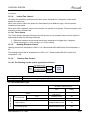
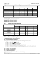
7 outdoor fan speeds are determined for each model. 3 speeds for cool and dry modes, and 3
speeds for heat mode, and a very low speed.
Outdoor fan speed is a function of compressor frequency and outdoor air temperature (OAT).
4 routines for fan control are determined. The control routine selection depends on operation
mode, compressor speed, outdoor air temperature (OAT) and heat sink temperature (HST).
Routine
A
B
C
D
Conditions
Heating with OAT < 150C
or
Cooling with OAT > 200C, or HST > 500C
or
Faulty OAT
Cooling with 200C > OAT > 500C
Cooling with 70C > OAT
Heating with OAT > 150C
Compressor Frequency (CF)
CF= 0
10 CF < OFLowFreq
10 CF < OFMedFreq
OFMedFreq CF
Outdoor Fan Speed
Routine A Routine B
OFF
OFF
Low
Low
Medium
Low
High
Low
Routine C
OFF
Very Low
Very Low
Low
Routine D
OFF
Low
Low
Medium
When compressor is switched to OFF and the heat sink temperature is above 55 degrees, the
outdoor fan will remain ON in low speed for up to 3 minutes.
11.1.10
EEV (electronic Expansion valve) Control
EEV opening is defined as EEV = EEV OL + EEVCV
EEVOL is the initial EEV opening as a function of the compressor frequency, operation mode, unit
model and capacity.
EEVCV is a correction value for the EEV opening that is based on the compressor temperature.
During the first 10 minutes of compressor operation EEV CV = 0.
Once the first 10 minutes are over, the correction value is calculated as follow: EEVCV(n) =
EEVCV(N-1) + EEVCTT
EEVCTT is the correction based on the compressor temperature. A target compressor temperature
is set depending on frequency and outdoor air temperature, and the actual compressor
temperature is compared to the target temperature to set the required correction to the EEV
opening.
11.1.11
Reversing Valve (RV) Control
Reversing valve is on in heat mode.
Switching of RV state is done only after compressor is off for over 3 minutes.
11.1.12
Ioniser Control
Ioniser is on when unit is on AND indoor fan is on AND Ioniser power switch (on Ioniser) is on.
SM PNXADCI 1-A.1 GB
11-3
CONTROL SYSTEM
11.1.13
Electro Static Filter )ESF( Control
ESF is on when ESF switch is on, Safety switch is pressed, unit is on, AND indoor fan is on.
11.1.14
Base Heater Control
When OAT is connected, Base Heater will be on when unit is in heating and OAT<20C.
When OAT is disconnected, Base Heater will be on when unit is in heating.
11.2
Fan Mode
In high/ medium/ low indoor fan user setting, unit will operate fan in selected speed.
In AutoFan user setting, fan speed will be adjusting automatically according to the difference
between actual room temperature and user set point temperature.
11.3
Cool Mode
NLOAD is calculated according to the difference between actual room temperature and user set
point temperature by PI control.
In high/ medium/ low indoor fan user setting, unit will operate fan in selected speed.
In AutoFan user setting, fan speed will be ad8usted automatically according to the calculated
NLOAD.
11.4
Heat Mode
NLOAD is calculated according to the difference between actual room temperature and user set
point temperature by PI control.
In high/ medium/ low indoor fan user setting, unit will operate fan in selected speed.
In AutoFan user setting, fan speed will be adng to the calculated
NLOAD.
11.4.1
Temperature Compensation
In wall mounted, ducted, and cassette models, 3 degrees are reduced from room temperature
reading (except when in I-Feel mode), to compensate for temperature difference between high and
low areas in the heated room, and for coil heat radiation on room thermistor.
The temperature compensation can be enabled/disabled by shortening of J2 on the indoor unit
controller.
Model
Wall mounted
Cassette
Ducted
Floor/Ceiling
11-4
J2 Shorted
Compensation
Disabled
Compensation Enabled
Compensation Enabled
Compensation
Disabled
J2 Opened
Compensation Enabled
Compensation Disabled
Compensation Disabled
Compensation Enabled
SM PNXADCI 1-A.1 GB
CONTROL SYSTEM
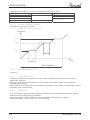
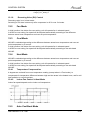
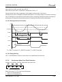
11.4.2
Indoor Fan Control in Heat Mode
Indoor fan speed depends on the indoor coil temperature:
ICTST
11.5
IC T V L
ICTL
ICTH
IC T T
Auto Cool/Heat Mode
When in auto cool heat mode unit will automatically select between cool and heat mode according
to the difference between actual room temperature and user set point temperature )¨T(.
Unit will switch from cool to heat when compressor is off for 3 minutes, and ¨T < -3.
Unit will switch from heat to cool when compressor is off for 5 minutes, and ¨T < -3.
11.6
Dry Mode
As long as room temperature is higher then the set point, indoor fan will work in low speed and
compressor will work between 0 and MaxNLOADIF1C
Hz.
When the room temperature is lower than the set point, compressor will be switched OFF and
indoor fan will cycle 3 minutes OFF, 1 minute ON.
11.7
Protections
There are 5 protection codes.
Normal (Norm) – unit operate normally.
Stop Rise (SR) – compressor frequency can not be raised but does not have to be decreased.
HzDown1 (D1) – Compressor frequency is reduced by 2 to 5 Hz per minute.
HzDown2 (D2) – Compressor frequency is reduced by 5 to 10 Hz per minute.
Stop Compressor (SC) – Compressor is stopped.
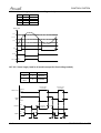
11.7.1
ICT
ICT < -2
-2 ICT < 0
0 ICT < 2
2 ICT < 4
4 ICT < 6
6 ICT < 8
8 ICT
Indoor Coil Defrost Protection
ICT Trend
Fast
Increasing
SC
D1
SR
SR
Norm
Norm
Normal
SM PNXADCI 1-A.1 GB
Increasing
No change
Decreasing
SC
D1
SR
SR
Norm
Norm
SC
D2
D1
SR
SR
Norm
SC
D2
D2
D1
SR
SR
Fast
Decreasing
SC
D2
D2
D2
D1
SR
11-5
CONTROL SYSTEM
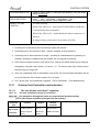
11.7.2
Indoor Coil over Heating Protection
ICT
ICT> 55
53 <ICT 55
49 < ICT 53
47 < ICT 49
45 < ICT 47
43 < ICT 45
ICT 43
11.7.3
ICT Trend
Fast
Decreasing
SC
D1
SR
SR
Norm
Norm
Normal
Decreasing
No Change
Increasing
SC
D1
SR
SR
Norm
Norm
SC
D2
D1
SR
SR
Norm
SC
D2
D2
D1
SR
SR
Fast
Increasing
SC
D2
D2
D2
D1
SR
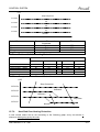
Compressor over Heating Protection
Compressor temperature can be in one of 5 control zones )4 in protection, and 1 normal(,
according to the following chart.
CTT
Stop-Compresor
CTTOH4
P3
CTTOH3
P2
CTTOH2
P1
CTTOH1
Normal
Control Status
P1
P2
P3
Stop Compressor
11.7.4
Compressor Temperature
Increases
Norm
D1
D2
SC
Else
SR
SR
D1
Compressor over Current Protection
CCR
Stop-Compresor
CCROC4
HzDown2
CCROC3
HzDown1
CCROC2
Stop-Rise
CCROC1
Normal
11-6
SM PNXADCI 1-A.1 GB
CONTROL SYSTEM
11.7.5
(NAfor
forDCI
GC259 and
and35)
GC 12 DCI)
Heat Sink Over Heating Protection (NA
HST
HST > 90
85 < HST 90
82 < HST 85
80 < HST 82
78 < HST 80
HST 78
11.7.6
HST Trend
Decreasing
SC
D1
SR
SR
Norm
Normal
No Change
SC
D2
D1
SR
Norm
Increasing
SC
D2
D2
D1
SR
Outdoor Coil Deicing Protection
11.7.6.1 Deicing Starting Conditions
Deicing operation will start when either one of the following conditions exist:
Case 1: OCT < OAT – 8 AND TLD > DI
Case 2: OCT < OAT – 12 AND TLD > 30 minutes.
Case 3: OCT is Invalid AND TLD > DI
Case 4: Unit is just switched to STBY AND OCT < OAT - 8
Case 5: NLOAD = 0 AND OCT < OAT -8
OCT – Outdoor Coil Temperature
OAT – Outdoor Air Temperature
TLD – Time from Last Deicing
DI – Deicing Interval (Time Interval Between Two Deicing)
Deicing interval time when compressor is first started in heat mode, is 10 minutes if OCT < -2, and
is 40 minutes in other cases.
Deicing interval time is changed (increased/ decreased in 10 minutes steps) as a function of
deicing time. If deicing time is shorter then former deicing time, the deicing interval time will be
increased. If deicing time is longer then former deicing time, the deicing interval time will be
decreased.
SM PNXADCI 1-A.1 GB
11-7
CONTROL SYSTEM
11.7.6.2 Deicing Protection Procedure
OCT
12
0
Threshold
ON
COMP
T1
T2
T1
max. 12 minutes
DT
HEAT
RV
COOL
T3
T3
ON
OFAN
OFF
EEVDeicerOpen
EEV
Any
T
36 seconds, T3 = 6 seconds
11.8
Condensate Water Over Flow Protection
Each of the pins P1, P2, P3 can have two options:
1 – When it is shorted with P4
0 – When it is not shorted to P4
11.8.1
3 Levels Logic (used in floor/ceiling models)
P2
0
1
1
0
11-8
P3
0
0
1
1
Level
L0
L1
L2&3
L4
SM PNXADCI 1-A.1 GB
CONTROL SYSTEM
Water Level
LEVEL4
LEVEL 3
LEVEL1
ON
Pump
OFF
ANY
NLOAD
0
BLINK
OPER LED NORMAL
11.8.2
1 Level Logic (used in all models except for floor/ceiling
models)
P2
Don`t
care
Don`t
care
P3
Level
1
Normal
0
Overflow
Overflow when
unit is ON
Overflow
Water Level
Overflow when
unit is OFF
Normal
ON
OPER
LED
OFF
BLINK
ANY
NLOAD
NLOAD is
forced to 0
0
ON
PUMP
OFF
8 min
11.9
8 min
8 min
Indoor Unit Dry Contact
Indoor unit Dry contact has two alternative functions that are selected by J8.
Function
Contact = Open
Contact = Short
J8 = Open
Presence Detector Connection No Limit
Forced to STBY
J8 = Open
Power Shedding Function
No Limit
Limit NLOAD
SM PNXADCI 1-A.1 GB
11-9
CONTROL SYSTEM
11.10
Operating the Unit from the Mode Button
Forced operation allows to start, stop and operate in Cooling or Heating, in pre-set temperature
according to the following table:
Forced operation Mode
Cooling
Heating
Pre-set Temperature
200C
280C
11.11
On Unit Controls and Indicators
11.11.1
Indoor Unit Controller Controls and Indicators For All Models
Except for Floor/Ceiling model
STAND BY
INDICATOR
OPERATION INDICATOR
TIMER INDICATOR
FILTER INDICATOR
COOLING INDICATOR
HEATING INDICATOR
Mode SWITCH
(COOL/HEAT/OFF)
RESET / FILTER
SWITCH
11-10
Lights up when the Air Conditioner is connected to power and ready to
receive the R/C commands
Lights up during operation.
Blinks for 300 msec., to announce that a R/C infrared
signal has
been received and stored.
Blinks continuously during protections (according to the relevant spec
section).
Lights up during Timer and Sleep operation.
Lights up when Air Filter needs to be cleaned.
Lights up when system is switched to Cool Mode by using the Mode
Switch on the unit.
Lights up when system is switched Heat Mode by using the Mode
Switch on the unit.
Every short pressing , the next operation mode is selected, in this order
:
SB ĺ Cool Mode ĺ Heat Mode ĺ SB ĺ
In long pressing system enters diagnostic mode.
For short pressing:
When Filter LED is on - turn off the FILTER INDICATOR after a clean
filter has been reinstalled.
When Filter LED is off able/disable the buzzer announcer, if
selected.
SM PNXADCI 1-A.1 GB
CONTROL SYSTEM
11.11.2
Indoor Unit Controls and Indicators for LCD Display
(Low)
STBY
OFF
Cool
SPT(1*)
Heat
SPT(1*)
Auto
SPT(1*)
Fan
SPT(1*)
Dry
SPT(1*)
OFF(2*)
ON(2*)
ON(2*)
ON(2*)
ON(2*)
ON(2*)
OFF(2*)
OFF
OFF(2*)
OFF(2*)
OFF(2*)
OFF(2*)
OFF(2*)
OFF
User
setting
IFAN
speed
User
setting
IFAN
speed
User
setting
IFAN
speed
User
setting
IFAN
speed
User
setting
IFAN
speed
OFF
ON(3*)
ON(3*)
OFF
ON(3*)
ON(3*)
ON(3*)
ON(3*)
OFF
ON(3*)
(Med)
OFF
(High)
OFF
(Turbo)
OFF
(Auto)
Backlight(red)
OFF
Backlight(green) OFF
SM PNXADCI 1-A.1 GB
11-11
CONTROL SYSTEM
11.11.3
Indoor Unit Controller Controls and Indicators for Floor/Ceiling
Model
STANDBY
INDICATOR
Lights up when the Air Conditioner is connected to power and is ready
for operation
OPERATE
INDICATOR (4)
1. Lights up during operation.
2. Blinks for 300 msec., to announce that a R/C infrared
signal
has been received and stored.
3. Blinks continuously during protections (according to the relevant spec
section).
TIMER
INDICATOR
FILTER
INDICATOR
COOLING
INDICATOR
HEATING
INDICATOR
FAN MODE
(4)
INDICATOR
FAN SPEED
INDICATORS
Lights up during Timer and Sleep operation.
TEMP.
SETTING
INDICATORS
FAN SPEED
BUTTON
TEMP.
SETTING UP
BUTTON
TEMP.
SETTING
DOWN BUTTON
MODE
BUTTON
POWER
BUTTON
RESET /
FILTER
BUTTON
11.11.4
1. Lights up when Air Filter needs to be cleaned.
2. Blinks during Water Over Flow in PXD models. (Cf. Sect. 7.3)
Lights up when system is switched to Cool Mode by using the Mode
Switch on the unit.
Lights up when system is switched Heat Mode by using the Mode
Switch on the unit.
Lights up in Fan Mode activated by local switches.
L
-- Lights up when IFAN setting is Low.
M
-- Lights up when IFAN setting is Medium.
H
-- Lights up when IFAN setting is High.
A
-- Lights up when IFAN setting is Auto.
Each one of the seven indicators indicates the following SPT: 18, 20,
22, 24, 26, 28, 30 ]oc[. The odd number temperatures are indicated by
turning on the two adcent indicators.
Press this button to change the speed of the IFAN. Each pressing
change the speed in the sequence of:
..... L ĺ 0 ĺ H ĺ Auto ĺ L ĺ ...
Pressing this button increases the SPT by 1oC.
Note: The Max SPT is 30oC.
Pressing this button decreases the SPT by 1oC.
Note: The Min SPT is 18oC.
Every short pressing , the next operation mode is selected, in this order
:
SB ĺ Cool Mode ĺ Heat Mode ĺ SB ĺ
In long pressing system enters diagnostic mode.
Toggle the unit between OPER & STBY modes.
For short pressing:
When Filter LED is on - turn off the FILTER INDICATOR after a clean
filter has been reinstalled.
When Filter LED is off able/disable the buzzer announcer, if
selected.
In long pressing system enters set up mode (if in SB).
Outdoor Unit Controller Indicators
Unit has three LED
SB LED is ON when power is ON (230 VAC, even when no communication).
STATUS LED is ON when COMP is ON, and Blinks according to diagnostics mode definitions
when either fault or protection occurs.
FAULT LED Blinks according to diagnostics mode definitions when either fault or protection
occurs.
11-12
SM PNXADCI 1-A.1 GB
CONTROL SYSTEM
11.12
Jumper Setting
11.12 .1
Indoor Unit Controller
0 = Open Jumper (disconnect jumper).
1 = Close Jumper (connect jumper).
Self test Jumper – J1
J1
1
0
OPERATION
SELF-TEST
NORMAL
Compensation Jumper – J2
Model
Wall Mounted
Floor/Ceiling
Ducted/cassette
J2 (Default)
0
1
1
Compensation
Activated
Deactivated
Activated
Family selection Jumper – J3, J4 and J5
Family
J5
0
0
0
0
1
1
1
1
Reserved
Reserved
Reserved
Wall Mounted (WNG/FLO)
Floor/Ceiling (PXD)
Reserved
Ducted (LS)
Cassette (K)
J4
0
0
1
1
0
0
1
1
J3
0
1
0
1
0
1
0
1
Jumper Setting
IDU Model
J8
J7
J6
J5
J4
J3
FLO 9
0
0
0
0
1
1
FLO 12
0
1
0
0
1
1
FLO 18
0
0
1
0
0
0
FLO 28
0
0
1
0
0
1
SX 9
0
0
0
1
0
0
SX 12
0
1
0
1
0
0
SX 18
1
0
0
1
0
0
K9
0
0
0
1
1
1
K 12
0
1
0
1
1
1
K 18
1
0
0
1
1
1
LS12
0
1
0
1
1
0
)RUZDOOPRXQWHGXQLWV-XPSHUVMMFDQEHFRQ¿JXUHGE\VHUYLFH All other jumpers on
the above table are factory default (cannot be changed by service).
)RUXQLWW\SHVDV&DVVHWWHVÀRRUFHLOLQJDQGGXFWHGMXPSHUVDUHVHWE\DPRGHOSOXJ
SM PNXADCI 1-A.1 GB
11-13
CONTROL SYSTEM
Model selection Jumper – J7, J8
Model
J8
J7
A
0
0
B
0
1
C
1
0
D
1
1
J9- Presence Detector/Power Shedding
OPERATION
Presence Detector
Power Shedding
J9
0
1
Jumper – J10
OPERATION
WNG DCI LCD
LED
11.12.2
J10
0
1
Outdoor Unit Controller
JP9 JUMPER LAYOUT
Reserved (PIN
ODU3 (PIN 7)
9)
GND (PIN 10)
GND (PIN 8)
ODU2
(PIN 5)
ODU1
GND
(PIN 6)
GND
(PIN 3)
(PIN 4)
ODU0
GND
(PIN 1)
(PIN 2)
ODU MODEL SELECTION
ODU3
OFF
OFF
OFF
OFF
OFF
OFF
OFF
OFF
ON (PIN7 & PIN8)
ON (PIN7 & PIN8)
ON (PIN7 & PIN8)
ON (PIN7 & PIN8)
ON (PIN7 & PIN8)
ON (PIN7 & PIN8)
ON (PIN7 & PIN8)
ON (PIN7 & PIN8)
ODU2
OFF
OFF
OFF
OFF
ON (PIN5 & PIN6)
ON (PIN5 & PIN6)
ON (PIN5 & PIN6)
ON (PIN5 & PIN6)
OFF
OFF
OFF
OFF
ON (PIN5 & PIN6)
ON (PIN5 & PIN6)
ON (PIN5 & PIN6)
ON (PIN5 & PIN6)
11.13
Test Mode
11.13.1
Entering Test Mode
ODU1
OFF
OFF
ON (PIN3 & PIN4)
ON (PIN3 & PIN4)
OFF
OFF
ON (PIN3 & PIN4)
ON (PIN3 & PIN4)
OFF
OFF
ON (PIN3 & PIN4)
ON (PIN3 & PIN4)
OFF
OFF
ON (PIN3 & PIN4)
ON (PIN3 ? PIN4)
ODU0
OFF
ON (PIN1 & PIN2)
OFF
ON (PIN1 & PIN2)
OFF
ON (PIN1 & PIN2)
OFF
ON (PIN1 & PIN2)
OFF
ON (PIN1 & PIN2)
OFF
ON (PIN1 & PIN2)
OFF
ON (PIN1 & PIN2)
OFF
ON (PIN1 & PIN2)
ODU Model
Reserved
A (DCI 25)
B (DCI 35)
C (DCI 50)
D
E (Duo)
F
G
H
I
J
K
L
M
N
O
System can enter Test mode in two ways:
Automatically when the following conditions exists for 30 minutes continuously:
Mode = Cool, Set point =16, Room temperature = 27±1, Outdoor temperature = 35±1
Or
Mode = Heat, Set point = 30, Room temperature = 20±1, Outdoor temperature = 7±1
Manually when entering diagnostics with the following settings:
Mode = Cool, Set point = 16
Mode = Heat, Set point = 30
11-14
SM PNXADCI 1-A.1 GB
CONTROL SYSTEM
11.13.2
Unit Operation in Test Mode
In test mode, the unit will operate in fixed settings according to the indoor fan speed setting:
Indoor Fan Speed Setting
Unit Setting
Low
Minimum Capacity Setting
High
Nominal Capacity Setting
Auto
Maximum Capacity Setting
During test mode, protections are disabled, except for stop compressor status.
11.14
SW Parameters
11.14.1
Indoor Units SW Parameters
General Parameters for All Models:
3DUDPHWHUVGH¿QLQJWKHLQGRRUIDQVSHHGDVDIXQFWLRQRI,QGRRU&RLOWHPSHUDWXUHLQ
KHDWPRGH,&7
ICTST Speed ICT to stop indoor fan
ICTVLSpeed
ICT to go down to very low speed
ICTLSpeed
ICT to start in very low speed
ICTHSpeed
ICT to start in increase speed from very low
ICTTSpeed
ICT to enable Turbo fan speed
25
28
30
32
40
Model Depended Parameters:
WDOO0RXQWHG0RGHOV
'&,9
'&,
1/2$'OLPLWVDVDIXQFWLRQRIVHOHFWHGLQGRRUIDQVSHHG
MaxNLOADIF1C
40
40
MaxNLOADIF2C
53
53
MaxNLOADIF3C
120
120
MaxNLOADIF4C
127
127
MaxNLOADIF5C
127
127
,QGRRU)DQVSHHGV
IFVLOWC
700
700
IFLOWC
800
800
IFMEDC
900
950
IFHIGHC
1050
1100
IFTURBOC
1150
1200
IFVLOWH
700
700
IFLOWH
800
850
IFMEDH
950
1000
IFHIGHH
1100
1150
IFTURBOH
1200
1250
1RPLQDO&RPSUHVVRU)UHTXHQF\
NomLoadC
40
62
NomLoadH
55
67
&DVVHWWH0RGHOV
Parameter Name
K9
.
.S
.
1/2$'OLPLWVDVDIXQFWLRQRIVHOHFWHGLQGRRUIDQVSHHG
MaxNLOADIF1C
40
40
40
40
MaxNLOADIF2C
53
56
56
60
MaxNLOADIF3C
120
90
90
90
MaxNLOADIF4C
127
90
90
90
MaxNLOADIF5C
127
90
90
90
1RPLQDO&RPSUHVVRU)UHTXHQF\
NomLoadC
40
60
56
63
3DUDPHWHUQDPH
NomLoadH
SM PNXADCI 1-A.1 GB
55
69
73
80
11-15
CONTROL SYSTEM
11.14.2
Outdoor Units SW Parameters
Parameter Name
DCI 9
DCI 12
DCI 18
DCI 50 DUO
Compressor Parameters
MinFreqC
30
33
20
20
MaxFreqC
64
80
85
97
MinFreqH
30
35
20
26
MaxFreqH
81
93
99
106
Step1Freq
60
60
60
60
Step2Freq
70
70
70
80
Step3Freq
90
90
90
90
Frequency limits as a function of outdoor air temperature
MaxFreqAsOATC
50
50
64
62
MaxFreqAsOAT1H
65
75
85
85
MaxFreqAsOAT2H
60
60
60
60
Compressor Over Heating Protection
CTTOH1
94
94
94
90
CTTOH2
98
98
98
95
CTTOH3
102
102
102
102
CTTOH4
105
105
105
105
Compressor Over Current Protection [A]
CCR01
7.1
7.1
10
10
CCR02
7.5
7.5
10.5
10.5
CCR03
7.9
7.9
10.8
10.8
CCR04
8.3
8.3
11.2
11.2
Outdoor Fan Speed (RPM)
VL
200
200
200
200
OFLOWC
550
550
600
600
OFMEDC
700
700
760
830
OFMAXC
830
830
920
920
OFLOWH
550
550
600
600
OFMEDH
700
700
830
920
OFMAXH
830
830
1000
1000
Outdoor Fan Limit Control
11-16
OFLowFreq
45
45
40
40
OFMedFreq
57
57
70
70
SM PNXADCI 1-A.1 GB
CONTROL SYSTEM
12.
CONTROL SYSTEM FOR PNXA 18/21/24
12.1
Electronic Control
12.1.1
General Functions and Operating Rules (for single split models)
The DCI software is fully parametric.
All the model dependent parameters are shown in Blue color and with Italic style [parameter].
The parameters values are given in the last section of this control logic chapter of the service
manual.
12.1.2
System Operation Concept
The control function is divided between indoor and outdoor unit controllers. Indoor unit is the system
‘Master’, requesting the outdoor unit for cooling/heating capacity supply. The outdoor unit is the
system ‘Slave’ and it must supply the required capacity unless it enters into a protection mode
avoiding it from supplying the requested capacity.
The capacity request is transferred via indoor to outdoor communication, and is represented by a
parameter called ‘NLOAD’. NLOAD is an integer number with values between 0 and 127, and it
represents the heat or cool load felt by the indoor unit.
12.1.3
Compressor Frequency Control
12.1.3.1 NLOAD setting
The NLOAD setting is done by the indoor unit controller, based on a PI control scheme.
The actual NLOAD to be sent to the outdoor unit controller is based on the preliminary LOAD
calculation, the indoor fan speed, and the power shedding function.
NLOAD limits as a function of indoor fan speed:
Indoor Fan Speed Maximum NLOAD Cooling
Maximum NLOAD Heating
Low
Max NLOADIF1C
127
Medium
Max NLOADIF2C
127
High
Max NLOADIF3C
127
Turbo
Max NLOADIF4C
127
Auto
Max NLOADIF5C
127
12.1.3.2 Target Frequency Setting
The compressor target frequency is set by the following table, according to the NLOAD number
received from the indoor unit.
NLOAD
0
0 < NLOAD ≤
MinFreq
>MinFreq
Target Frequency [Hz]
0
MinFreq
MaxFreq − MinFreq
⋅ {min (NLOAD, LoadDeadZone) − MinFreq} + MinFreq
LoadDeadZone − MinFreq
MinFreq
MaxFreq
SM PNXADCI 1-A.1 GB
Definitions
Cool
MinFreqC
MaxFreqC
Heat
MinFreqH
MaxFreqH
12-1
CONTROL SYSTEM
LoadDeadZoneC
LoadDeadZoneH
LoadDeadZone
During running time (unlike starting) Compressor can operate only in its allowed frequency
range.
The lower allowed frequency is extracted from the following:
Mode
MinFreq
MinFreqA
HP
HPA
Cool
MinFreqC MinFreqCA HPAtMinFreqC HPAtMinFreqCA
Heat
MinFreqH MinFreqHA HPAtMinFreqH HPAtMinFreqHA
Notes:
1. HP stands for High Pressure.
2. Pressure is represented by the following:
•
Cooling: max {OMT, OCT} in cooling mode,
•
Heating (Multi split): maximum ICT among all active and available inactive IDUs in
heating mode.
•
Heating (Single Split): ICT
3. The above parameters are determined from the compressor specifications.
The higher allowed frequency is extracted from the following:
Mode
‘Unit Night Mode’
Maximum Frequency (MaxFreq)
On
MaxFreqC*0.75
Off
MaxFreqC
On
MaxFreqH*0.75
Off
MaxFreqH
Cool
Heat
12.1.3.3 Frequency Changes Control
Frequency change rate is 1 Hz/sec.
12.1.3.4 Compressor Starting Control
Frequency
Step 3
Step 2
Step 1
1
Minute
1
Minute
Time
Min 10 Minutes
12-2
SM PNXADCI 1-A.1 GB
CONTROL SYSTEM
12.1.3.5 Minimum On and Off Time
3 minutes.
12.1.4
Indoor Fan Control
10 Indoor fan speeds are determined for each model. 5 speeds for cool/dry/fan modes and 5
speeds for heat mode.
When user sets the indoor fan speed to a fixed speed (Low/ Medium/ High), unit will operate
constantly at set speed.
When Auto Fan is selected, indoor unit controller can operate in all speeds. The actual speed is set
according to the cool/heat load.
12.1.4.1 Turbo Speed
The Turbo speed is activated during the first 30 minutes of unit operation when auto fan speed is
selected and under the following conditions:
• Difference between set point and actual room temperature is bigger then 3 degrees.
• Room temperature > 22 for cooling, or < 25 for heating.
12.1.5
Heating Element Control
Heating element can be started if LOAD > 0.8 * MaximumNLOAD AND Indoor Coil temperature <
45.
The heating element will be stopped when LOAD < 0.5 * MaximumNLOAD OR if Indoor Coil
temperature > 50.
12.1.6
Outdoor Fan Control
12.1.6.1 The following are the speeds types(General Rules):
Speed
High
Low
Controlled by
Relay
Triac (27% to 85% effective voltage)
12.1.6.2 OFAN Speed Type
AC Motor (OFANType=2)
Triac
Relay
Cool
Effective voltage
R.M.S (V%)
OFMinPercentC
NA
Heat
OFMinPercentH
NA
‘B’:
- Higher Speed
OFNNoiseMaxPercent
NA
‘C’:
- Protection Speed
OFNNoiseMaxPercent
NA
Speed Variable
Metric
‘A’:
- Lower Speed
SM PNXADCI 1-A.1 GB
12-3
CONTROL SYSTEM
‘D’:
(Night Mode Speed)
NightPercent
NA
Off
On
Off
On
‘E’:
- End of Deicer
- When Compressor changes to off (Ventilation)
- OMT and OCT fault in heat mode
‘F’:
- Test Mode
12.1.6.3 OFAN Operation
With keeping the OFAN general rules above in the highest priority, the operation of the OFAN will
be operating as the following:
Cooling
•
12.1.7
heating
The Triac and the Relay can never be activated at the same time
EEV (electronic Expansion valve) Control
EEV opening is defined as EEV = EEVOL + EEVCV
• EEVOL is the initial EEV opening as a function of the compressor frequency, operation mode,
unit model and capacity.
• EEVCV is a correction value for the EEV opening that is based on the Target CTT and
discharge superhea.
• During the first 5 minutes of compressor operation EEVCV = 0.
• Once the first 5 minutes are over, the correction value is calculated as follow: EEVCV =
EEVSH Discharge + EEVTarget CTT
• EEVSH Discharge
For cooling, SHDischargeC = CTT- OMT
For Heating, SHDischargeH= CTT- ICT
• EEVTarget CTT
For cooling, Target CTT = Target_CTT_Alpha_C *OMT
- Target_CTT_Beta_C *ICT
+Target_CTT_Gamma_C *Actual Compressor Frequency
+Target_CTT_Delta_C
For Heating, Target CTT = Target_CTT_Alpha_H*ICT
- Target_CTT_Beta_H*OCT
12-4
SM PNXADCI 1-A.1 GB
CONTROL SYSTEM
+Target_CTT_Gamma_H*Actual Compressor Frequency
+Target_CTT_Delta_H
12.1.8
Reversing Valve (RV) Control
Reversing valve is on in heat mode.
Switching of RV state is done only after compressor is off for over 3 minutes.
12.2
Fan Mode
In high/ medium/ low indoor fan user setting, unit will operate fan in selected speed.
In AutoFan user setting, fan speed will be adjusted automatically according to the difference
between actual room temperature and user set point temperature.
12.3
Cool Mode
NLOAD is calculated according to the difference between actual room temperature and user set
point temperature by PI control.
In high/ medium/ low indoor fan user setting, unit will operate fan in selected speed.
In AutoFan user setting, fan speed will be adjusted automatically according to the calculated
NLOAD.
12.4
Heat Mode
NLOAD is calculated according to the difference between actual room temperature and user set
point temperature by PI control.
In high/ medium/ low indoor fan user setting, unit will operate fan in selected speed.
In AutoFan user setting, fan speed will be adjusted automatically according to the calculated
NLOAD.
12.4.1
Temperature Compensation
4 degrees are reduced from room temperature reading (except when in I-Feel mode), to
compensate for temperature difference between high and low areas in the heated room, and for coil
heat radiation on room thermistor.
12.4.2
Indoor Fan Control in Heat Mode
Indoor fan speed depends on the indoor coil temperature:
ICTST ICTVL
12.5
ICTL
ICTH
ICTT
Auto Cool/Heat Mode
SM PNXADCI 1-A.1 GB
12-5
CONTROL SYSTEM
When in auto cool heat mode unit will automatically select between cool and heat mode according
to the difference between actual room temperature and user set point temperature (∆T).
Unit will switch from cool to heat when compressor is off for 3 minutes, and ∆T < -3.
Unit will switch from heat to cool when compressor is off for 5 minutes, and ∆T < -3.
12.6
Dry Mode
As long as room temperature is higher then the set point, indoor fan will work in low speed and
compressor will work between 0 and MaxNLOADIF1C Hz.
When the room temperature is lower than the set point, compressor will be switched OFF and
indoor fan will cycle 3 minutes OFF, 1 minute ON.
12.7
Protections
There are 5 protection codes.
Normal (Norm) – unit operate normally.
Stop Rise (SR) – compressor frequency can not be raised but does not have to be decreased.
HzDown1 (D1) – Compressor frequency is reduced by Down1 Hz/min.
HzDown2 (D2) – Compressor frequency is reduced by Down2 Hz/min.
Stop Compressor (SC) – Compressor is stopped.
12.7.1
Indoor Coil Defrost Protection
ICT
ICT < -2
-2 ≤ ICT < 0
0 ≤ ICT < 2
2 ≤ ICT < 4
4 ≤ ICT < 6
6 ≤ ICT < 8
8 ≤ ICT
12.7.2
Fast
Increasing
Increasing
ICT Trend
No change
Decreasing
Fast
Decreasing
SC
D1
SR
SR
Norm
Norm
SC
D1
SR
SR
Norm
Norm
SC
D2
D1
SR
SR
Norm
SC
D2
D2
D1
SR
SR
SC
D2
D2
D2
D1
SR
Normal
Indoor Coil over Heating Protection
ICT
ICT > 55
53 < ICT ≤ 55
49 < ICT ≤ 53
47 < ICT ≤ 49
45 < ICT ≤ 47
43 < ICT ≤ 45
ICT ≤ 43
12.7.3
Fast
Decreasing
Decreasing
ICT Trend
No Change
Increasing
Fast
Increasing
SC
D1
SR
SR
Norm
Norm
SC
D1
SR
SR
Norm
Norm
SC
D2
D1
SR
SR
Norm
SC
D2
D2
D1
SR
SR
SC
D2
D2
D2
D1
SR
Normal
Compressor over Heating Protection
Compressor temperature can be in one of 5 control zones (4 in protection, and 1 normal), according
to the following chart.
12-6
SM PNXADCI 1-A.1 GB
CONTROL SYSTEM
CTT
Stop-Compresor
CTTOH4
P3
CTTOH3
P2
CTTOH2
P1
CTTOH1
Normal
Control Status
Compressor Temperature
Increases
P1
Norm
P2
D1
P3
D2
Stop Compressor
SC
12.7.4
Outdoor Coil Overheating Protection
OMTn
OMTn ≥ HPC5
HPC4 ≤ OMTn < HPC5
HPC3 ≤ OMTn < HPC4
HPC2 ≤ OMTn < HPC3
HPC1≤ OMTn < HPC2
OMTn < HPC1
12.7.5
Else
SR
SR
D1
OMTn-OMTn-1
<-1
-1
SC
D2
D1
SR
Norm
SC
D2
D1
SR
Norm
0
SC
D2
D1
SR
Norm
Norm
1
>1
SC
D2
D1
SR
Norm
SC
D2
D1
SR
Norm
Compressor over Current Protection
CCR
Stop-Compresor
CCROC4
HzDown2
CCROC3
HzDown1
CCROC2
Stop-Rise
CCROC1
Normal
12.7.6
Heat Sink Over Heating Protection
A new control status will be set according to the following graph every one-minute or
whenever when going up by the rows.
SM PNXADCI 1-A.1 GB
12-7
CONTROL SYSTEM
HSTn is the current reading of HST and HSTn-1 is the last reading of HST.
HSTn
HSTn-HSTn-1
<-1
-1
0
1
>1
HSTn > HSTOH5
SC
SC
SC
SC
SC
HSTOH4 ≤ HSTn < HSTOH5
D1
D1
D2
D2
D2
HSTOH3 ≤ HSTn < HSTOH4
SR
SR
D1
D2
D2
HSTOH2 ≤ HSTn < HSTOH3
SR
SR
SR
D1
D1
HSTOH1 ≤ HSTn < HSTOH2
Norm
Norm
Norm
SR
SR
HSTn < HSTOH1
Norm
(*) Normal (Norm) – No protection status is ON.
Stop-Rise (SR) – System is in protection.
HzDown1 (D1) - System is in protection.
HzDown2 (D2) - System is in protection.
12.7.7
System Over Power Protection
Powern
Powern > OVRPWR5
OVRPWR4 ≤ Powern <
OVRPWR5
OVRPWR3 ≤ Powern <
OVRPWR4
OVRPWR2 ≤ Powern <
OVRPWR3
OVRPWR1 ≤ Powern <
OVRPWR2
Powern < OVRPWR1
12.7.8
Powern-Powern-1
<-50
[-50,-1]
0
[1,50]
>50
SC
D1
SC
D1
SC
D2
SC
D2
SC
D2
SR
SR
D1
D2
D2
SR
SR
SR
D1
D1
Norm
Norm
Norm
SR
SR
Norm
Outdoor Coil Deicing Protection
In the deicing protection, IFAN is forced OFF.
12.7.8.1 Deicing Starting Conditions
Deicing operation will start when either one of the following conditions exist:
• Case 1: OCT<–DST AND TLD > DI
• Case 2: OCT<-4 AND TLD>100 minutes
• Case 3: OCT is Invalid AND TLD > DI
• Case 4: Unit is just switched to STBY AND OCT<-DST
• Case 5: compressor is stopped during heating operation, OCT<-DST AND TLD>DI,
OCT – Outdoor Coil Temperature
OAT – Outdoor Air Temperature
TLD – Time from Last Deicing
DI – Deicing Interval (Time Interval Between Two Deicing)
DT- Deicing Time
12-8
SM PNXADCI 1-A.1 GB
CONTROL SYSTEM
DST is defined as:
When OAT>0 or OAT is invalid; then DST=8
When OAT≤0; then DST= round down (-DeicerCoef * OAT) + 8
Deicing interval time when compressor is first started in heat mode is 30 minutes.
Deicing interval time is changed (increased/ decreased in 10 minutes steps) as a function of deicing
time. If deicing time is shorter than former deicing time, the deicing interval time will be increased. If
deicing time is longer than former deicing time, the deicing interval time will be decreased.
12.7.8.2 Deicing Protection Procedure
OCT
12
0
Threshold
COMP
ON
T1
T2
T1
max. 12 minutes
RV
COOL
OFAN
DT
HEAT
T3
T3
ON
OFF
EEVDeicerOpen
EEV
Any
T1 = DEICT1 seconds, T2 = DEICT2 seconds, T3 = DEICT3 seconds
12.7.8.3 Exiting Deicing
OCT > OCTExitDeicer or Deicer current time is over MaxDeicerTime minutes.
12.7.9
Condensate Water Over Flow Protection
Outdoor unit receives “overflow’ signal from the indoor side.
Each of the pins P1, P2, P3 can have two options:
1 – When it is shorted with P4
0 – When it is not shorted to P4
SM PNXADCI 1-A.1 GB
12-9
CONTROL SYSTEM
12.7.9.1 3 Levels Logic (used in floor/ceiling models)
P2
0
1
1
0
P3
0
0
1
1
Level
L0
L1
L2&3
L4
Water Level
LEVEL4
LEVEL2&3
LEVEL1
ON
Pump
OFF
ANY
NLOAD
0
BLINK
OPER LED NORMAL
12.7.9.2 1 Level Logic (used in all models except for floor/ceiling models)
P2
Don’t
care
Don’t
care
P3
Level
1
Normal
0
Overflow
Overflow when
unit is ON
Overflow
Water Level
Overflow when
unit is OFF
Normal
ON
OPER
LED
OFF
BLINK
ANY
NLOAD
NLOAD is
forced to 0
0
ON
PUMP
OFF
8 min
12-10
8 min
8 min
SM PNXADCI 1-A.1 GB
CONTROL SYSTEM
12.7.10
Exceeding operation conditions
Exceeding limits state
Indoor
Mode
request
Indoor
Hydro
(Family 31)
Indoor
Non Hydro
(Family is not 31)
1
0 (or OAT
faulty)
A=47
B=-11
B=-18
A=+40
A=47
B=-11
B=-18
A=+30
Idle
Idle
Idle
Idle
Cooling
Cooling
Heating
Heating
Cooling
Cooling
Heating
Heating
12.8
EnableExceedCond
Outdoor conditions
Normal state
(default)
Outdoor mode
Cool
Cool
Heat
Heat
Indoor Unit Dry Contact
Indoor unit Dry contact has two alternative functions that are selected by J8.
Function
Contact = Open
Contact = Short
J8 = Open
Presence Detector Connection No Limit
Forced to STBY
J8 = Short
Power Shedding Function
No Limit
Limit NLOAD
12.9
Operating the Unit from the Mode Button
Forced operation allows to start, stop and operate in Cooling or Heating, in pre-set
temperature according to the following table:
12.10
Forced operation Mode
Pre-set Temperature
Cooling
200C
Heating
280C
Indoor Unit Controllers and Indicators
STAND BY
INDICATOR
1.
OPERATION
INDICATOR
1.
Lights up during operation.
2.
Blinks for 300 msec., to announce that a R/C infrared
Lights up when the Air Conditioner is connected to power
and ready to receive the R/C commands
signal has been received and stored.
3.
Blinks continuously during protections (according to the
relevant spec section).
TIMER INDICATOR
FILTER INDICATOR
COOLING INDICATOR
SM PNXADCI 1-A.1 GB
Lights up during Timer and Sleep operation.
Lights up when Air Filter needs to be cleaned.
Lights up when system is switched to Cool Mode by using the
Mode Switch on the unit.
12-11
CONTROL SYSTEM
HEATING INDICATOR
Mode SWITCH
(COOL/HEAT/OFF)
RESET / FILTER
SWITCH
Lights up when system is switched Heat Mode by using the Mode
Switch on the unit.
Every short pressing , the next operation mode is selected, in this
order :
SB → Cool Mode → Heat Mode → SB → …
In long pressing system enters diagnostic mode.
For short pressing:
When Filter LED is on - turn off the FILTER INDICATOR after
a clean filter has been reinstalled.
When Filter LED is off – enable/disable the buzzer announcer, if
selected.
In long pressing system enters set up mode (if in SB).
Note:
1. Pressing time is defined as the time between press and release.
2. If pressing time is one second or less – press is consider as short pressing.
3. If pressing time is three seconds or longer – pressing is considered as long pressing. In
between, pressing is undetermined and system will not respond to pressing.
4. PXD units are always forced to enter either Cool, Heat or Fan Mode whenever its setting is
changed by using the local buttons (i.e. items H - L). The other modes (Dry & Auto) can be
selected only by using a R/C.
5. If the unit’s operating mode is selected by using a R/C, the Cool and Heat indicators will not
be turned ON even if the current mode is Cool or Heat.
6. In ST group units, the Heat Mode is skipped. That is Cool Mode → Fan Mode directly.
12.11
Outdoor Unit Controllers and Indicators
12.11.1
The user display uses three 7 segments.
12.11.1.1
The user interface concept is Tree menus.
12.11.1.2
The navigation through the menu can be performed by either the key
pad or RC8 remote controller (through infra red receiver).
Command
Function
Keypad
Remote
Type
Up or Down
command
12-12
RC8 sketch:
controller
Scrolling among
Up or
Up: Set Point ‘+’
options (up and
Down key
Down: Set Point
down).
button.
‘-‘
SM PNXADCI 1-A.1 GB
CONTROL SYSTEM
Selection
command
Go down one level
in the menu or
select an option.
Select
button
Escaping
Go up one level in
Escape
command
the menu
button
FAN mode
Oper/STBY
Note: the buttons above are selected according to RC8 design (refer to RC8 specifications) for the
technician convenient use.
1. The navigation type selection, remote controller or keypad, is set through software
parameter: HMIType=0 (keypad), HMIType=1 (remote controller)
2. The following table summarizes the remote controller commands:
Command
Type
Pressed
Button
SPT
Oper
Up
Down
‘+’
‘-‘
30
16
0
0
Escape
Enter
Reserved
Reserved
Oper
FAN
Sleep
Horizontal
Louver
I-FEEL
Other
Don’t care
Don’t care
Don’t care
Don’t care
1
0
0
0
Values on the IR protocol
Horizontal
FAN
Sleep
Louver
0
0
0
0
0
0
0
01
0
0
0
0
1
0
0
0
0
1
Reserved
Don’t care
0
0
0
0
20
0
0
0
0
Notes:
1. The zeros stated above must be checked in order to judge for proper message.
2.
I-FEEL
Other bits
0
0
0
0
0
0
0
0
0
0
0
0
1
0
0
0
Proper checksum has to be performed according to the RC7 specifications.
3. For any remote controller command, the most right ‘dot’ will blink for 1 second in order to
acknowledge the command is received.
12.11.1.3
Active selection or status will be indicated by blinking the display.
12.11.2
Keys functionality
o Scrolling will be done whenever the button is pressed.
o When scrolling alpha values, if the scroll button is held in, the selection will change at the rate
of one step per second.
o The display will not roll over during selection (for example stop/Ode/Dia/Stp/Par/stop)
12.11.3
Menus
12.11.3.1
General
All the green colored items will be deactivated for single split units.
12.11.3.2
Main Menu
Technician Test (tt)
Installation Test (it)
SM PNXADCI 1-A.1 GB
12-13
CONTROL SYSTEM
Diagnostics (dia)
Set Up (Stp)
Status (Stt)
Notes:
1. The default presentation will be alternation among:
o
the mode of the unit (Cl/Ht/Sb) shown for 2 sec.
o
ID + the detected IDUs number shown for 2 sec.
o
Active fault (among ODU or IDUs), each to be shown for 2 sec.
2. In diagnostics menu:
o
xx means failure code.
o
Maximum 5 faults are presented for each unit (each IDUs/ODU). When no faults “-“ sign will be shown.
o
The active faults have higher priority for presentation than non active ones.
o
Non active faults are presented according to their chronological order, starting from the
latest one.
o
Whenever a new active fault occurs, it will be presented immediately.
o
Active faults are blinking, where non active ones do not.
3. Exiting ‘Status’ menu and its sub-menus back to the main menu is done by either pressing
escape or after continuous 60 minutes out of any press.
4. Technician Test mode, once is selected, it cannot last more than predefined time. Refer to
technician test for details, Sect..
5. All the menus, except Status and its sub-menu, Technician Test once selected, are
automatically exited to the main menu after 10 continuous minute out of any press.
6. When Technician test cool or heat menus are selected (operative), it will be blinking
constantly until, this menu is escaped.
7. When the installation test begins, the system will show up count down based (refer to the
installation test sect. At the end of the installation test, the result will be presented.
8. For the indoor diagnostics, whenever there is no-communication with indoor unit or indoor
unit is not detected, ‘no-communication’ will be shown under the relevant indoor unit
diagnostics. In addition to the indoor diagnostics, these faults will be also shown as well
under the default show.
9. When Alpha and numeric values are combined, they will be separated by dot.
10. For technician mode presentation, the active setting target compressor frequency will be
presented directly upon entry. The active selected value will be blinking. The set target
compressor frequency will be enabled to be scrolled up and down within the minimum and
maximum operating frequency values (the values do depend on the outdoor model setting
as well as the operation mode- cool or heat)
12-14
SM PNXADCI 1-A.1 GB
CONTROL SYSTEM
11. For technician mode presentation, whenever the system exit technician mode due any of the
faults listed under Sect., the HMI will show the fault in the same way to Diagnostics sub
menu.
Fault Code:
Problem
No
1
OCT is shorted/disconnected
2
CTT is shorted/disconnected
3
HST is shorted/disconnected
4
OAT is shorted/disconnected
5
OMT is shorted/disconnected
6
RGT is shorted/disconnected
7
RLT is shorted/disconnected
8
Reserved
9
Reserved
10 Reserved
11 Compressor IPM Fault / IPM Driver Pin / Compressor
Current Sensor Fault
12 Bad EEPROM
13 DC under voltage
14 DC over voltage
15 AC under voltage/AC over Voltage/Zero Crossing
detection
16 Mismatch between IDU & ODU models
17 No Communication
18 System Over Power
19 PFC Current sensor
20 Heat sink Over Heating
21 Deicing
22 Compressor Over Heating
23 Compressor Over Current
24 No OFAN Feedback
25 OFAN IPM fault / OFAN IPM Driver Pin
26 Compressor Lock
27 Bad Communication
28 Missing ODU configuration
29 Undefined ODU Model
30 Outdoor/Indoor Coil Overheating
31 Operation conditions are exceeded
12.12
Jumper Settings
12.12.1
Indoor Unit Controller
5
0
0
0
0
0
0
0
0
0
0
0
4
0
0
0
0
0
0
0
1
1
1
1
3
0
0
0
1
1
1
1
0
0
0
0
2
0
1
1
0
0
1
1
0
0
1
1
1
1
0
1
0
1
0
1
0
1
0
1
0
0
0
0
1
1
1
1
1
1
1
1
0
0
1
1
0
1
0
1
1
1
1
1
1
1
1
1
1
1
1
1
1
1
1
1
0
0
0
0
0
0
0
0
1
1
1
1
1
1
1
1
0
0
0
0
1
1
1
1
0
0
0
0
1
1
1
1
0
0
1
1
0
0
1
1
0
0
1
1
0
0
1
1
0
1
0
1
0
1
0
1
0
1
0
1
0
1
0
1
12.12.1.1 Hardware Jumpers
0 = Open Jumper (disconnect jumper).
1 = Close Jumper (connect jumper).
SM PNXADCI 1-A.1 GB
12-15
CONTROL SYSTEM
Self test Jumper – J1
OPERATION
SELF-TEST
NORMAL
J1
1
0
Compensation Jumper – J2
Model
WNG/WNG18/WNG30/WSA
PXD/AC/NPXD
LS/K/KS/AS/AD/DNG/KN
J2 (Default)
0
1
1
Family selection Jumper – J3, J4 ,J5and J6
Family
J6
J5
J4
Compensation
Activated
Deactivated
Activated
J3
AS
0 0
0
0
AC
0
0
0
1
AD
0
0
1
0
0
0
1
1
WNG
0 1
0
0
PXD
0
1
0
1
KS
0
1
1
0
LS
0 1
1
1
K
1 0
0
0
WNG18
1 0
0
1
WNG30
NA
Delta 50
1 0
1
1
WSA
NA
DNG
1 1
0
1
KN
NA
NPXD
1 1
1
1
Reserved
Note: 1. Delta 50 is used for Delta Product. This family occupies family No. 10 on the
communication level.
Model selection Jumper – J7, J8
Model
J8 J7
A
0
0
B
0
1
C
1
0
D
1
1
12.12.1.2 Software Jumpers
Property
EEPROM DATA (J1)
‘Thermostatic Stop- Heat’ (J2)
‘Heat to STBY’ (J3)
Water Level Protection (J4)
0
Use ROM*
Deactivated
Deactivated
1 Level
Enable Test Mode (J5)
Deactivated
* Default values (used in the ROM)
12-16
1
Use EEPROM
Activated
Activated
3 Levels
Activated*
2
NA
NA
NA
No Water Protectionignore
NA
SM PNXADCI 1-A.1 GB
CONTROL SYSTEM
AC
AD
WNG
PXD
KS
LS
K
WNG18
WNG30
Reserve
d
WSA
DNG
KN
NPXD
Reserve
d
‘Thermostatic
Stop- Heat’
(J2)
‘Heat to
STBY’ (J3)
Water Level
Protection
(J4)
AS
Default SW jumpers according to the family (used in the ROM)
Property
1
1
1
1
0
0
0
1
1
1
0
0
1
0
0
0
1
1
1
1
1
0
0
1
1
1
0
0
1
1
1
0
0
2
0
2
1
0
2
0
2
2
0
2
0
0
1
0
J1 – EEPROM/ROM setting
When J1 is 1, IDU will use model/family/general parameters from EEPROM. If EEPROM is invalid,
IDU will ignore J1 and use/copy the ROM pointed by the selected jumpers (will also set an
according fault).
12.12.2
Outdoor Unit Controller
12.12.2.1
Hardware Jumpers
JP9 JUMPER LAYOUT
ODU4 (PIN 9)
GND (PIN 10)
ODU3 (PIN 7)
GND (PIN 8)
ODU2 (PIN 5)
GND (PIN 6)
ODU1 (PIN 3)
GND (PIN 4)
ODU0 (PIN 1)
GND (PIN 2)
ODU2
OFF
OFF
12.12.2.2
ON
ODU0
ODU3
ON
ODU1
ODU4
ODU MODEL SELECTION
ON
ODU
Model
Compressor Type
(Manufacturer/Model/# poles)
Single Split
Multi Split
S (DCR60)
Panasonic, 4 poles, DA150
Software Jumpers
Property
EEPROM DATA (J1)
* Default values (used in the ROM)
0
Use ROM*
1
Use EEPROM
J1 – EEPROM/ROM setting
When J1 is 1, ODU will use model/general parameters from EEPROM. If EEPROM is invalid, ODU
will ignore J1 and use/copy the ROM pointed by the selected jumpers (will also set an according
fault).
SM PNXADCI 1-A.1 GB
12-17
CONTROL SYSTEM
12.13
Test Mode
12.13.1
Entering Test Mode
System can enter Test mode in two ways:
• Automatically when the following conditions exists for 30 minutes continuously:
o Mode = Cool, Set point = 16, Room temperature = 27±1, Outdoor temperature =
35±1
Or
o Mode = Heat, Set point = 30, Room temperature = 20±1, Outdoor temperature = 7±1
• Manually when entering diagnostics with the following settings:
o Mode = Cool, Set point = 16
o Mode = Heat, Set point = 30
• Enteringthrough the outdoor unit (initialted by the outdoor unit)
12.13.2
Unit Operation in Test Mode
When entering through indoor:
-
IFAN speed and NLOAD will be set in the following ways.
User Setting
IFAN Speed
Low/Med
High
Turbo/Auto
IFAN variable speed
Cool
IFAN_TEST_COOL_MIN
Heat
IFAN_TEST_HEAT_MIN
Cool
IFAN_TEST_COOL_NOM
Heat
IFAN_TEST_HEAT_NOM
Cool
IFAN_TEST_COOL_MAX
Heat
IFAN_TEST_HEAT_MAX
Fixed
Speed
NLOAD
Low
10
Turbo
NomLoadC (at
Cool)
NomLoadH (at
heat)
Turbo
127
When entering through outdoor:
ODU mode
IDU mode
IFAN Variable Speed
IFAN_TEST_COOL_NOM
Cooling
Cooling
IFAN_TEST_HEAT_NOM
Heating
Heating
Notes:
1. For deicer, the relevant deicer logic should be followed.
IFAN fix
speed
Turbo
Turbo
NLOAD
NomLoadC
NomLoadH
2. the operation led blinks ON/OFF cycles with 2 seconds cycle time when entering by
outdoor.
Note:
1. For the protections, except for water level protections, only the “Stop-Compressor” status
will be operative. For other protection statuses, the system will behave as in normal one.
2. The vertical louver should be Test_Mode_ Angle ,it should be vertical.Louvers angles will be
set according to the IDU family and Mode:
12-18
SM PNXADCI 1-A.1 GB
TROUBLESHOOTING
13.
TROUBLESHOOTING
13.1
ELECTRICAL & CONTROL TROUBLESHOOTING
WARNING!!!
When Power Up – the whole outdoor unit controller, including the wiring, is under
HIGH VOLTAGE!!!
Never open the Outdoor unit before turning off the Power!!!
When turned off, the system is still charged (400V)!!!
It takes about 4 Min. to discharge the system.
Touching the controller before discharging may cause an electrical shock!!!
13.1.1
No
1
2
3
4
5
6
7
Single Split system failures and corrective actions
SYMPTOM
Power supply indicator
(Red LED) does not light
up.
Unit does not respond to
remote control message
PROBABLE
CAUSE
No power supply
Remote control
message not
reached the indoor
unit
CORRECTIVE ACTION
Check power supply. If power supply
is OK, check display and display
wiring. if OK, replace controller.
Check remote control batteries, if
batteries are OK, check display and
display wiring, if OK, replace display
PCB.
If still not OK replace controller.
Replace display PCB.
If still not OK replace controller.
Unit responds to remote
control message but
Operate indicator (Green
LED) does not light up
Indoor fan does not start
(louvers are opened and
Green LED does light
up)
Problem with
display PCB
Indoor fan works when
unit is OFF, and indoor
fan speed is not
changed by remote
control command.
Compressor does not
start
PCB problem
Change to high speed and Check
power supply to motor is higher than
130VAC (for triack controlled motor)
or higher than 220VAC for fixed
speed motors, if OK replace
capacitor, if not OK replace
controller
Replace controller
Electronics control
problem or
protection
Electronic control
or power supply
problem
Perform diagnostics (See 13.1.3
below), and follow the actions
described.
Perform diagnostics (See 13.1.3
below), and follow the actions
described.
Compressor stops
during operation and
Green LED remains on
SM PNXADCI 1-A.1 GB
Unit in heat mode
and coil is still not
warm.
Problem with PCB
or capacitor
Change to cool mode and check.
13-1
TROUBLESHOOTING
No
8
9
10
11
12
13
14
15
16
13.1.2
SYMPTOM
Compressor is on but
outdoor fan does not
work
Unit works in wrong
mode (cool instead of
heat or heat instead of
cool)
All components are
operating properly but
no cooling or no heating
Compressor is over
heated and unit does not
generate capacity
Units goes into
protections and
compressor is stopped
with no clear reason
Compressor motor is
generating noise and no
suction occurs
Water leakage from
indoor unit
Freezing of outdoor unit
in heat mode and
outdoor unit base is
blocked with ice
Unit operates with wrong
fan speeds or wrong
frequency
PROBABLE
CAUSE
Problem with
outdoor electronics
or outdoor fan
Electronics or
power connection
to RV
CORRECTIVE ACTION
Refrigerant leak
Check outdoor fan motor according
to the procedure in section 13.2.3
below, if not OK replace controller
Check RV power connections, if OK,
Check RV operation with direct
230VAC power supply, if OK,
Replace outdoor controller.
Check refrigeration system.
EEV problem
Check EEV
Control problem or
refrigeration
system problem
Perform diagnostics (See 13.1.3
below), and follow the actions
described.
Phase order to
compressor is
wrong
Indoor unit
drainage tube is
blocked
Check compressor phase order.
Check and open drainage tube.
Connect base heater.
Wrong jumper
settings
Perform diagnostics (See 13.1.3
below), and check if units is
operating by EEPROM parameters.
Checking the refrigeration system
Checking system pressures and other thermodynamic measures should be done when system
is in Test Mode (in Test mode, system operates in fixed settings). The performance curves
given in this manual are given for unit performance in test mode when high indoor fan speed is
selected.
Entering test mode:
Set unit to Cool/16 degrees/High indoor fan speed, or Heat/30 degrees/High indoor fan speed,
and enter diagnostics.
13.1.3
Judgment by Indoor/Outdoor Unit Diagnostics
Enter diagnostics mode - press for five seconds Mode/Reset button in any operation mode.
Acknowledgment is by 3 short beeps and lights of all Display LED’s. Then, The units will enter
into Indoor and Outdoor unit diagnostic modes.
During the Outdoor unit diagnostics all three Indoor LED’s (STBY/Operate, Filter and Timer)
are blinking. When Indoor diagnostics is displayed, all three LED’s (STBY/Operate, Filter and
Timer) are ON.
13-2
SM PNXADCI 1-A.1 GB
TROUBLESHOOTING
When system enters diagnostics mode, only one fault code is shown. Order of priority is from
the lower to the higher number. Diagnostics is continuously ON as long as power is ON. The
current system operation mode will not be changed.
If no fault occurred in the system, no fault code will be displayed during normal operation
mode. The last fault code will be displayed even if the system has recovered from that fault.
The last fault will be deleted from the EEPROM after the system has exit diagnostics mode.
In diagnostics mode, system fault / status will be indicated by blinking of Filter & Timer LEDs.
The coding method will be as follows:
Filter LED will blink 5 times in 5 seconds, and then will be shut off for the next 5 seconds. Timer
LED will blink during the same 5 seconds according to the following Indoor / Outdoor unit tables:
Note: 0 – OFF, 1-ON
13.1.3.1 Indoor unit Diagnostics
Problem
No
5
4
3
2
1
1
2
3
4
5
7
8
9
10
11
…
RT-1 is disconnected
RT-1 is shorted
RT-2 is disconnected
RT-2 is shorted
Reserved
Communication mismatch
No Communication
No Encoder
Reserved
Outdoor Unit Fault
Reserved
17
18
19
20
Defrost protection
Deicing Protection
Outdoor Unit Protection
Indoor Coil HP Protection
21
Reserved
22
Reserved
24
EEPROM Not Updated
25
Bad EEPROM
26
Bad Communication
27
Using EEPROM data
SM PNXADCI 1-A.1 GB
13-3
TROUBLESHOOTING
No
Problem
28
Model A
5
4
3
2
1
29
Model B
30
Model C
31
Model D
13.1.3.2 Indoor unit diagnosis and corrective actions
No.
1
2
3
4
5
6
7
8
9
Fault
Sensor failures of
all types
Communication
mismatch
Probable Cause
Corrective Action
Check sensor connections or
replace sensor
Replace Indoor controller
Indoor and Outdoor
controllers are with different
versions
Communication
or grounding Check Indoor to Outdoor
No Communication
wiring is not good.
wiring and grounding
Indoor electronics or motor Check motor wiring, if ok,
No Encoder
replace motor, if still not ok,
replace Indoor controller.
Outdoor Unit Fault Outdoor controller problem Switch to Outdoor
diagnostics.
System is using ROM
No action, unless special
EEPROM Not
parameters and not
parameters are required for
Updated
EEPROM parameters
unit operation.
No action, unless special
Bad EEPROM
parameters are required for
unit operation.
Communication quality is low Check Indoor to Outdoor
Bad
reliability
wiring and grounding
Communication
No problem. System is using
Using EEPROM
EEPRRRROM parameters
data
13.1.3.3 Outdoor unit Diagnostics
For GC 9/12 DCI
Problem
No
1 OCT is disconnected
2 OCT is shorted
3 CTT is disconnected
4 CTT is shorted
5 HST is disconnected (when enabled)
6 HST is shorted (when enabled)
7 OAT is disconnected (when enabled)
8 OAT is shorted (when enabled)
9 TSUC is disconnected (when enabled)
10 TSUC is shorted (when enabled)
13-4
5
0
0
0
0
0
0
0
0
0
0
4
0
0
0
0
0
0
0
1
1
1
3
0
0
0
1
1
1
1
0
0
0
2
0
1
1
0
0
1
1
0
0
1
1
1
0
1
0
1
0
1
0
1
0
SM PNXADCI 1-A.1 GB
TROUBLESHOOTING
No
11
12
13
14
15
16
17
18
20
21
22
23
24
25
26
27
Problem
IPM Fault
Bad EEPROM
DC under voltage
DC over voltage
AC under voltage
Indoor / Outdoor unit Communication
mismatch
No Communication
Reserved
Heat sink Over Heating
Deicing
Compressor Over Heating
Compressor Over Current
No OFAN Feedback
OFAN locked
Compressor Lock
Bad Communication
For YBD 018/22/24
Problem
No
1
OCT is shorted/disconnected
2
CTT is shorted/disconnected
3
HST is shorted/disconnected
4
OAT is shorted/disconnected
5
OMT is shorted/disconnected
6
RGT is shorted/disconnected
7
RLT is shorted/disconnected
8
Reserved
9
Reserved
10 Reserved
11 Compressor IPM Fault / IPM Driver Pin /
Compressor Current Sensor Fault
12 Bad EEPROM
13 DC under voltage
14 DC over voltage
15 AC under voltage/AC over Voltage/
Zero Crossing detection
16 Mismatch between IDU & ODU models
17 No Communication
18 System Over Power
19 PFC Current sensor
20 Heat sink Over Heating
21 Deicing
22 Compressor Over Heating
23 Compressor Over Current
24 No OFAN Feedback
25 OFAN IPM fault / OFAN IPM Driver Pin
26 Compressor Lock
SM PNXADCI 1-A.1 GB
5
0
0
0
0
0
1
4
1
1
1
1
1
0
3
0
1
1
1
1
0
2
1
0
0
1
1
0
1
1
0
1
0
1
0
1
1
1
1
1
1
1
1
1
1
0
0
0
0
0
0
1
1
1
1
0
0
1
1
1
1
0
0
0
0
0
1
0
0
1
1
0
0
1
1
1
0
0
1
0
1
0
1
0
1
5
0
0
0
0
0
0
0
0
0
0
0
4
0
0
0
0
0
0
0
1
1
1
1
3
0
0
0
1
1
1
1
0
0
0
0
2
0
1
1
0
0
1
1
0
0
1
1
1
1
0
1
0
1
0
1
0
1
0
1
0
0
0
0
1
1
1
1
1
1
1
1
0
0
1
1
0
1
0
1
1
1
1
1
1
1
1
1
1
1
1
0
0
0
0
0
0
0
0
1
1
1
0
0
0
0
1
1
1
1
0
0
0
0
0
1
1
0
0
1
1
0
0
1
0
1
0
1
0
1
0
1
0
1
0
13-5
TROUBLESHOOTING
27
28
29
30
31
Bad Communication
Missing ODU configuration
Undefined ODU Model
Outdoor/Indoor Coil Overheating
Operation conditions are exceeded
1
1
1
1
1
1
1
1
1
1
0
1
1
1
1
1
0
0
1
1
1
0
1
0
1
13.1.3.4 Outdoor unit diagnosis and corrective actions
No.
Probable Cause
Fault
Sensors failures of all
types
IPM Fault
Electronics HW
problem
Bad EEPROM
DC under/over Voltage
Electronics HW
problem
AC under Voltage
Indoor / Outdoor unit
Communication mismatch
No Communication
Indoor and Outdoor
controllers are with
different versions
Communication or
grounding wiring is not
good.
Compressor Lock
Bad Communication
13.1.4
Communication quality is
low reliability
Corrective Action
Check sensors
connections or replace
sensors.
Check all wiring and
jumper settings, if OK,
replace electronics.
No action, unless special
parameters are required
for unit operation.
Check outdoor unit power
supply voltage
Check outdoor unit power
supply voltage
Replace Indoor controller
Check Indoor to Outdoor
wiring and grounding
Switch unit to STBY and
restart
Check Indoor to Outdoor
wiring and grounding
Judgement by MegaTool
MegaTool is a special tool to monitor the system states.
Using MegaTool requires:
•
A computer with RS232C port.
•
A connection wire for MegaTool.
•
A special MegaTool software.
Use MegaTool according to following procedure:
•
Setup MegaTool software: copy the software to the computer.
•
Connect RS232C port in computer with MegaTool port in Indoor/Outdoor unit
controller by the connection wire.
•
Run the software and choose the COM port, you can monitor the A/C system state in
monitor tab.
13.2
13-6
Simple procedures for checking the Main Parts
SM PNXADCI 1-A.1 GB
TROUBLESHOOTING
13.2.1
Checking Mains Voltage.
Confirm that the Mains voltage is between 198 and 264 VAC. If Mains voltage is out of this
range, abnormal operation of the system is expected. If in range check the Power (Circuit)
Breaker and look for broken or loosed cable lugs or wiring mistake(s).
13.2.2
Checking Power Input.
If Indoor unit power LED is unlighted, power down the system and check the fuse of the Indoor
unit. If the fuse is OK replace the Indoor unit controller. If the fuse has blown, replace the fuse
and power up again.
Checking Power Input procedure for the Outdoor unit is the same as with the Indoor unit.
13.2.3
Checking the Outdoor Fan Motor.
Enter Test Mode (where the OFAN speed is high)
check the voltage between two pins( Hi and N ) of connector Controller OFAN, normal voltage
is 220VAC.
13.2.4
Checking the Compressor.
The compressor is brushless permanence magnetic DC motor. Three coil resistance is
same. Check the resistance between three poles. The normal value should be below 0.7
ohm. Pay attention U,V, W are respective to connect to RED,BROWN,BLACK wires.
13.2.5
Checking the Reverse Valve (RV).
Running in heating mode, check the voltage between two pins of reverse valve connector,
normal voltage is 220VAC.
13.3
Precaution, Advise and Notice Items
13.3.1
High voltage in Outdoor unit controller.
Whole controller, including the wires that are connected to the Outdoor unit controller may
have the potential hazard voltage when power is on. Touching the Outdoor unit controller
may cause an electrical shock.
Advise: Don’t touch the naked lead wire and don’t insert finger, conductor or anything else
into the controller when power is on.
13.3.2
Charged Capacitors
Three large-capacity electrolytic capacitors are used in the Outdoor unit controller.
Therefore, charging voltage (380VDC) remains after power down. Discharging takes about
four minutes after power is off. Touching the Outdoor unit controller before discharging
may cause an electrical shock.
13.3.3
•
•
Additional advises
When disassemble the controller or the front panel, turn off the power supply.
When connecting or disconnecting the connectors on the PCB, hold the whole housing,
don’t pull the wire.
There are sharp fringes and sting on shell. Use gloves when disassemble
SM PNXADCI 1-A.1 GB
13-7
EXPLODED VIEW & SPARE PART LIST
14.
EXPLODED VIEW & SPARE PART LIST
14.1
Exploded view of indoor unit: PNXA 9/12 DCI
1
2
40
3
39
4
5
38
37
36
6
35
7
34
33
32
8
31
30
29
9
10
11
12
13
28
27
26
25
24
23
22
21
20
19
18
14
17
16
15
SM PNXADCI 1-A.1 GB
14-1
EXPLODED VIEW & SPARE PART LIST
14.2
No.
1
2
3
4
5
6
7
8
9
9
10
11
12
13
14
15
16
17
18
19
20
21
22
23
24
25
26
27
28
29
30
31
32
33
34
35
36
37
38
39
40
14-2
Spare part list of indoor Unit: PNXA 9/12 DCI
PN
465800009
465800016
4518655
4519132
4519744
465720059
4526952
4526389
4518664
4522754
4527434
4518638
4526953
4518640
4518641
4518662
4518661
4518730
4518670
4518654
4519864R
4518650
452969400
452969500
4521158R
4520061R
4520278R
4519147
465320006
467300079R
4518666
467300067R
438082
4519813
465340012
4518663
4519338
none
453042500
4518651
none
4518682
4518646
452867800R
4518657
4518656
4519900
467430000
467480001
4526951
465800018
Description
Grill A Assy./ LEX7/9/12/14 for Airwell
Grill A Assy./ LEX7/9/12/14 for Electra
Air Filter
Active Carbon Static Fiber filter
Low Temperature Catalyst Fiber Filter
Front Frame Assy./ LEX7/9/12/14
Screw Cover
R410A EVAPORATOR ASSY HPI DC WNG9/12
Draining Hose(ordinary)
Draining Hose(For Aust.)
Air Outlet Assy
Upper Louver
Lower Louver
Vert. Louver A
Vert. Louver B
Bearing assy fan
Fan assy plastic D91
Rear panel assy
WNG INSTALLATION PLATE
Tube Bracket
Motor (LEX DCI25/35 and LEX7/9/12/14 with new function)
Motor Cover
Step Motor A
Step Motor B
Power cord cable (Euro.)
Power cord cable(Israel)
Power cord cable(Without plug)
Power Cord Clip
Wire Fixing Block
Display Board Assy./ LEX25/35DCI(With new function)
Sensor Braket
LEX DCI Indoor Controller With Vertical Louver
Thermistor Indoor coil(BLACK)
Thermistor room
Terminal Cover
ELECTROSTATIC FLITER WNG-1
FILTER FRAME(Optional)
none
Remote controller/RC4-I-1 EHK P/N 974-710-00
Cover Side Motor
none
Gear BOX ASSY
Louver Support
Transformer For LEX DCI25/35 (Optional)
Tube Lock
Mounting Hook
IONIZER CABLE A (Optional)
Power Supply Unit /Ionizer(Optional)
Ionizer/WNG NWNG SERIES(Optional)
Ionizer Cover (Optional)
Air Inlet Frame A Assy.
Quantity
1
1
2
1
1
1
2
1
1
1
1
1
1
2
10
1
1
1
1
1
1
1
1
1
1
1
1
1
1
1
1
1
1
1
1
1
1
0
1
1
0
1
1
1
1
2
1
1
1
1
1
SM PNXADCI 1-A.1 GB
EXPLODED VIEW & SPARE PART LIST
14.3
Exploded view of indoor unit: PNXA 18/21/24 DCI
1
2
3
42
41
40
4
5
39
38
37
6
36
35
34
7
31
30
8
29
9
28
10
11
27
26
25
24
23
12
22
21
13
20
19
14
18
17
16
15
SM PNXADCI 1-A.1 GB
14-3
EXPLODED VIEW & SPARE PART LIST
14.4
Spare part list of indoor Unit: PNXA 18/21 DCI
No
PN.
Name
Qua.
1
465100078
Grill A/Lex-18 (RAL9003AW)
1
2
452919800
Filter
2
3
470500012
Nanometer Photocatalysis Deodorant Filter Lex18/24
1
3
470500015
465720388
Biological Sterilization Filter Lex18/24
Front Frame Assy./Glossy/LEX 50 DCI(VIESSMANN)
1
4
5
465340085
Screw Cover/Glossy/LEX 50 DCI(VIESSMANN)
3
6
453134600
1
7
465120023
Evaporator Assy.
Air Outlet Frame/LEX 50 DCI(VIESSMANN)
8
465210009
9
9
1
1
1
465160023
Drain Pipe for Europe / WNG18/24/30
Horizontal flap A(Viessmann)
465160024
Horizontal flap B(Viessmann)
1
10
465160017
Vertical flap B(Viessmann)
2
10
465160016
Vertical flap A(Viessmann)
12
11
4518662
Bearing assy fan
1
12
453024900
1
13
465700011
Impeller fan
Unit Housing/Glossy/LEX 50 DCI(VIESSMANN)
1
14
452920100
Mount bracket/WNG-18 (20)
1
15
465320017
Connect Plate/Unit housing/LEX 50 DCI (Viessmann)
1
16
453024500R
PG Motor
1
17
452918800
Cover/motor
1
18
453050200
STEP MOTOR A
1
18
453050300
STEP MOTOR B
1
20
453232000
Clip /Power cord
1
21
467300068R
Display Board /LEX DCI (With New Funtion)
1
22
4516263
SENSOR BASE
1
22
452919100
Support/sensor
1
23
467300258R
1
24
467400053
Controller / DCI IDU HAD 18
ICT Indoor Coil Temperature ¢6
25
467400025
( 650mm ) Indoor Air Inlet Temperature S
1
26
465340051
Terminal Cover (Viessmann)
1
29
467240025
Remote controller Assy.with batteries. RC-7i-1 467200037R
1
30
4518651
Cover Side Motor
1
31
453057900
1
34
464250070
Gear BOX ASSY
Support/Horizontal Flap/ LEX50 DCI(Viessmann)
2
36
465320033
TUBE LOCK (RAL9003AW)
1
40
465360039
Support/Bi Polar Ionizer/LEX 7/9/12/18
1
40
467480009
Ionizer/Bi-Polar ((Optional)
1
41
465160008
Air Inlet Frame A Assy/Lex-18
1
14-4
1
1
SM PNXADCI 1-A.1 GB
EXPLODED VIEW & SPARE PART LIST
14.5
Spare part list of indoor Unit: PNXA 24 DCI
No
PN.
Name
Qua.
1
465100078
Grill A/Lex-18 (RAL9003AW)
1
2
452919800
Filter
2
3
470500012
Nanometer Photocatalysis Deodorant Filter Lex18/24
1
3
470500015
465720388
Biological Sterilization Filter Lex18/24
Front Frame Assy./Glossy/LEX 50 DCI(VIESSMANN)
1
4
5
465340085
Screw Cover/Glossy/LEX 50 DCI(VIESSMANN)
3
6
453260400
1
7
465120023
Evaporator Assy.
Air Outlet Frame/LEX 50 DCI(VIESSMANN)
8
465210009
9
9
1
1
1
465160023
Drain Pipe for Europe / WNG18/24/30
Horizontal flap A(Viessmann)
465160024
Horizontal flap B(Viessmann)
1
10
465160017
Vertical flap B(Viessmann)
2
10
465160016
Vertical flap A(Viessmann)
12
11
4518662
Bearing assy fan
1
12
453024900
1
13
465700011
Impeller fan
Unit Housing/Glossy/LEX 50 DCI(VIESSMANN)
1
14
452920100
Mount bracket/WNG-18 (20)
1
15
465320017
Connect Plate/Unit housing/LEX 50 DCI (Viessmann)
1
16
453206800R
DC Motor
1
17
452918800
Cover/motor
1
18
453050200
STEP MOTOR A
1
18
453050300
STEP MOTOR B
1
20
453232000
Clip /Power cord
1
21
467300068R
Display Board /LEX DCI (With New Funtion)
1
22
4516263
SENSOR BASE
1
22
452919100
Support/sensor
1
23
467300259R
1
24
467400053
Controller / DCI IDU HAD 24
ICT Indoor Coil Temperature ¢6
25
467400025
( 650mm ) Indoor Air Inlet Temperature S
1
26
465340051
Terminal Cover (Viessmann)
1
29
467240025
Remote controller Assy.with batteries. RC-7i-1 467200037R
1
30
4518651
Cover Side Motor
1
31
453057900
1
34
464250070
Gear BOX ASSY
Support/Horizontal Flap/ LEX50 DCI(Viessmann)
2
36
465320033
TUBE LOCK (RAL9003AW)
1
40
465360039
Support/Bi Polar Ionizer/LEX 7/9/12/18
1
40
467480009
Ionizer/Bi-Polar ((Optional)
1
41
465160008
Air Inlet Frame A Assy/Lex-18
1
SM PNXADCI 1-A.1 GB
1
1
14-5
EXPLODED VIEW & SPARE PART LIST
14.6
14-6
Exploded view of outdoor Unit: GC 9/12 DCI
SM PNXADCI 1-A.1 GB
EXPLODED VIEW & SPARE PART LIST
14.7
No
1
2
3
4
5
6
7
8
9
10
11
14
15
17
20
21
21
22
22
23
24
25
26
27
28
29
30
31
32
33
34
35
36
37
38
39
40
41
33
42
43
Spare part list of outdoor Unit: GC 9/12 DCI
PN.
433218
4526340
464860054
4526476
4527092R
433215
4523060
4526299
467300037R
463300505
461010004
463300510
461000004
467030020
455015202
4526300
204107
4519188
467420013
465340080
465340081
461030007
461600059
461020004
4526221
4526204
467400055
467400026
467400056
452682802
4526827
4519606
433228
4526368
4526298
4519614
4526480
4519300
433225
4519607
464630001
4520036
4520090
SM PNXADCI 1-A.1 GB
Name
Front Panel A
Air inlet ring-420
Painting Insulation Plate Assy/ONG
Axial fan OD=401
DC MOTOR for DCI 25/35
Motor Support
Base Painting Assy.
Partition
Controller/Outdoor Units(DCI 1.8kW) EHK:906A099-03
Standard Valve Connect Pipe/Gas Valve
Gas Valve 3/8" R410A
Standard Valve Connect Pipe/Liquid Valve
Liquid Valve 1/4" R410A
Wire UL1015 16AWG L=210mm
ground wire
Therminal sheet
Cable clip Nylon
4 poles terminal block
5 Poles Terminal Block/ONG3-12RC DCI35 R410A
Valve Cover/PP+UV 5VA/ONG3
Valve Cover/With new function fresh air/PP+UV 5VA/ONG3
4-W valve coil /SHF(L)-4H/7H(DCI)
4-Way Valve Assy./DCI 35
4-W valve /SHF(L)-7H-34U
Compressor wire
DC INVERTER Compressor Assy 5RS102XAB
CTT Compressor Top Temperature Sensor
OAT Outdoor Air Temperature Sensor
OCT Outdoor Coil Temperature Sensor
EEV coil CAM-MD12FKS-2
Electronical expansion valve CAM-BD15 FKS-1
Right side panel (painting plate)
Back Side Net
condensor Soldering assy
Bridge
Painting Top Cover
Gasket for axial fan
Nut M5 L
Handle
Left Side Panel Painting Plate
Side Plate Painting Assy./right
DC Fan Motor Assy
Fresh air & pipe assy
Qua.
1
1
1
1
1
1
1
1
1
1
1
1
1
1
1
1
1
1
1
1
1
1
1
1
1
1
1
1
1
1
1
1
1
1
1
1
1
1
1
1
1
1
1
14-7
EXPLODED VIEW & SPARE PART LIST
14.8
14-8
Exploded view of outdoor Unit: YBD018
SM PNXADCI 1-A.1 GB
EXPLODED VIEW & SPARE PART LIST
14.9
NO
Spare part list of outdoor Unit: YBD018
PN
Name
Qua.
1
433218
Front Panel A
1
2
4526340
Air inlet ring-420
1
3
433223
Painting Insulation Plate
1
4
464250118
Fireproofing plate/ONG3 DIC
1
5
4519251
Axial Fan OD=400
1
6
466100034R
Metal Motor
1
7
4527203
Motor Support
1
8
464600094
Base Painting Assy.
1
9
464160024
Partition Plate
1
10
467550005R
Choke
1
11
467300233R
Controller
1
12
461000004
Liquid Valve 1/4" R410A
1
13
461010005
Gas Valve 1/2" R410A
1
14
460150020R
Compressor Assy./ Panasonic 5RS132ZAD21
1
15
4516540
ground wire
1
16
452823600
Therminal Plate Assy.
1
17
467420025
4 poles terminal block
1
18
204107
Cable clip Nylon
1
19
455000108
Double patch Capacitor for fan motor 2uF
1
20
465340080
Valve Cover
1
21
461600079
4-Way Valve Welding Assy.
1
22
461030007
4-W valve coil /SHF(L)-4H/7H(DCI)
1
23
461020004
4-W valve /SHF(L)-7H-34U
1
24
467000001
Compressor Power Cord
1
25
461040013
Electronic Expansion Valve DPF(Q)1.65C-63
1
26
461050014
EEV Coil QA(Q)12-HX-03
1
27
464210007
Φ7.94 sensor Clip
1
28
467400056
OCT Outdoor Coil Temperature Sensor
1
29
467400040
Sensor of OAT & OMT
1
30
467400200
CTT Compressor Top Temperature Sensor
1
31
4519606
Right side panel (painting plate)
1
32
433228
Back Side Net
1
33
462300127
Condenser Welding Assy.
34
4526298
Bridge
1
1
35
452813200
coil stopper
1
36
4519614
Painting Top Cover
1
37
4519300
Nut M5 L
1
38
433225
Handle
1
39
4519607
Left Side Panel Painting Plate
1
SM PNXADCI 1-A.1 GB
14-9
EXPLODED VIEW & SPARE PART LIST
14.10
14-10
Exploded view of outdoor Unit: YBD022
SM PNXADCI 1-A.1 GB
EXPLODED VIEW & SPARE PART LIST
14.11
No
1
2
3
4
5
6
7
8
9
10
11
12
13
14
15
16
17
18
19
20
21
22
23
24
25
26
27
28
29
30
31
32
33
34
35
36
37
38
39
40
41
42
Spare part list of outdoor Unit: YBD022
PN
4517144
452795700
4516786
4523141
4526841
4526510
466100048R
C60095900
Name
Fan Cover PP+UV/Grill A
Painted Left Cabinet Assy.
Painted Right Cabinet Assy.
Hexagon Locked Nut M10
Cusion for Fan
FAN D=460mm (3 blade)
Metal Motor
Motor Support
467400200
467400056
Compressor Top Temperature Sensor
Outdoor Coil Temperature Sensor
467400040
464600117
464160004
Condenser Middle Temperature Sensor/OAT & OMT
Base Plate Paint Assy.
Partition Plate
467000001
462300126
460170013R
461030007
463300650
461010005
Compressor Power Cord
Condenser Welding Assy.
Compressor Assy./ GMCC DA150S1C-20FZ
4-W valve Coil /SHF(L)-4H/7H(DCI)
Valve Connect Pipe/Gas Valve
Gas Valve 1/2" R410A
463300649
461000004
461040013
461050014
461020004
Valve Connect Pipe/Liquid Valve
Liquid Valve 1/4" R410A
Electronic Expansion Valve DPF(Q)1.65C-63
EEV Coil QA(Q)12-HX-03
4-W Valve /SHF(L)-7H-34U
461600097
464080008
465220012
4-Way Valve Welding Assy.
Rear Plate/Right Painting Assy.
Right Lifter/PP+UV 5VA
464080009
464800019
464080008
4516758
Rear Plate/ Left Painting Assy.
Guard Net/ODU Painting Assy.
Rear Plate/Right Painting Assy.
Small Handle
4516540
4513592
467420025
204107
455000104
453052900
4526585
Ground Wire
Ground Wire for Compressor
4 Poles Terminal Block
Cable Clip Nylon
Double patch Capacitor for fan motor 4uF
Terminal Plate Assy.
Connect for Motor Backet
467300233R
467550005R
464210007
4516788
Controller/ DCRS 2.8KW Sine Wave Main BD
Choke
Sensor Clip
Painted Top Cover Assy.
SM PNXADCI 1-A.1 GB
Qua.
1
1
1
1
1
1
1
1
1
1
1
1
1
1
1
1
1
1
1
1
1
1
1
1
1
1
1
1
1
1
1
1
1
1
1
1
1
1
1
1
1
1
14-11
EXPLODED VIEW & SPARE PART LIST
14.12
14-12
Exploded view of outdoor Unit: YBD024
SM PNXADCI 1-A.1 GB
EXPLODED VIEW & SPARE PART LIST
14.13
Spare part list of indoor Unit: YBD024
NO.
1
2
3
4
5
6
7
8
9
10
11
12
13
14
15
16
17
18
19
20
21
22
23
24
25
26
27
28
29
30
31
32
33
34
35
36
37
38
39
40
Item
465100000
4523652
4523758
452960400
461600055
461030003
4526522
466110008R
4522601
4523653
467400200
467400040
467400038
452809900
460090007R
452783600
452783200
453256100
4526080
4526513
4526514
464080007
465340082
4518950
464250093
204107
467300185R
464280003
461040013
461050014
462300002
453175500
453083800
467550002R
464730010
467300184R
464200026
4523657
4522600
465120013
SM PNXADCI 1-A.1 GB
Description
Grill/ DCI Trio
PAINTED LEFT CABINET ASSY
Nut M8 left
Outdoor Fan
4-Way Valve Assy.
4-way Valve Coil
FOUR-WAY VALVE R410A
DC Resin Motor
Right Handle
PAINTED RIGHT CABINET ASSY
Compressor Top Thermistor(CTT)
Condenser Middle Temperature Sensor/OAT & OMT
ODU COIL MIDDLE TEMPERATURE SENSOR
Base Plate Painting Assy.
Compressor Assy./ C-7RZ233H1A (SANYO ShenYang)
Oil Separator Assy.
Liquid-gas Separator
Support Painting Support Assy./Gas-Liquid Separator
Valve plate paint assy
LOW PRESS VALVE (R410A)
Hight press valve(R410A)
Right-Rear Plate/DCI 80 CR
Valve Cover/PP+UV 5VA/GC 30
Filter Drier BFK-053S
Protecting Plate /controller
Cable clip Nylon
Controller / DCI 80 CR Filter Board
Terminal Plate/ DCI 80Z
Electronic Expansion Valve DPF(Q)1.65C-63
EEV Coil QA(Q)12-HX-03
Condenser Assy.
Guard Net Painting Assy.
Support/OAT
Choke / DCI 80 CR
Partition Plate Assy./DCI 80Z
Controller / DCI 80 CR OUTDOOR BOX ASSY
Motor Support
PAINTED TOP COVER ASSY
Left Handle
Air Outlet Cover/DCI 80 CR R410a
Quan.
1
1
1
1
1
1
1
1
1
1
1
1
1
1
1
1
1
1
1
1
1
1
1
1
1
2
1
1
1
1
1
1
1
1
1
1
1
1
1
1
14-13
TUBING CONNECTIONS
15.
TUBING CONNECTIONS
When the outdoor unit is installed above the indoor unit an oil trap is required every 5m along the
suction line at the lowest point of the riser. In case the indoor unit is installed above the outdoor, no
trap is required.
SM PNXADCI 1-A.1 GB
15-1
APPENDIX A
APPENDIX A
INSTALLATION AND OPERATION MANUALS
SM PNXADCI 1-A.1 GB
16-1