1
Agilent N9360A
Multi UE Tester
CDMA2000 User Manual
Agilent Technologies
Notices
© Agilent Technologies, Inc. 2008
Manual Part Number
No part of this manual may be reproduced
in any form or by any means (including
electronic storage and retrieval or translation into a foreign language) without prior
agreement and written consent from
Agilent Technologies, Inc. as governed by
United States and international copyright
laws.
N9360-90706
Edition
Second Edition, March 2008
Printed in Malaysia
Agilent Technologies Microwave Products
(Malaysia) Sdn. Bhd.
Bayan Lepas Free Industrial Zone
11900 Penang, Malaysia
Warranty
The material contained in this document is provided “as is,” and is subject to being changed, without notice,
in future editions. Further, to the
maximum extent permitted by applicable law, Agilent disclaims all warranties, either express or implied,
with regard to this manual and any
information contained herein, including but not limited to the implied
warranties of merchantability and fitness for a particular purpose. Agilent
shall not be liable for errors or for
incidental or consequential damages
in connection with the furnishing,
use, or performance of this document
or of any information contained
herein. Should Agilent and the user
have a separate written agreement
with warranty terms covering the
material in this document that conflict with these terms, the warranty
terms in the separate agreement
shall control.
Technology Licenses
The hardware and/or software described
in this document are furnished under a
license and may be used or copied only in
accordance with the terms of such license.
Restricted Rights Legend
If software is for use in the performance of
a U.S. Government prime contract or subcontract, Software is delivered and
licensed as “Commercial computer software” as defined in DFAR 252.227-7014
(June 1995), or as a “commercial item” as
defined in FAR 2.101(a) or as “Restricted
computer software” as defined in FAR
52.227-19 (June 1987) or any equivalent
agency regulation or contract clause. Use,
duplication or disclosure of Software is
subject to Agilent Technologies’ standard
commercial license terms, and non-DOD
Departments and Agencies of the U.S.
Government will receive no greater than
Restricted Rights as defined in FAR
52.227-19(c)(1-2) (June 1987). U.S. Government users will receive no greater than
Limited Rights as defined in FAR 52.227-14
(June 1987) or DFAR 252.227-7015 (b)(2)
(November 1995), as applicable in any
technical data.
Safety Notices
CAUTION
A CAUTION notice denotes a hazard. It calls attention to an operating procedure, practice, or the like
that, if not correctly performed or
adhered to, could result in damage
to the product or loss of important
data. Do not proceed beyond a
CAUTION notice until the indicated
conditions are fully understood and
met.
WA RNING
A WARNING notice denotes a
hazard. It calls attention to an
operating procedure, practice, or
the like that, if not correctly performed or adhered to, could result
in personal injury or death. Do not
proceed beyond a WARNING
notice until the indicated conditions are fully understood and
met.
Preface
Thank-you for purchasing the Agilent N9360A Code Division Multiple
Access (cdma2000) Option. This option is the cdma2000 software for the
Agilent N9360A Multi UE Tester.
• Before using the tester, the user is advised to read this manual
carefully to ensure correct usage and also to fully utilize the tester
capability.
• This manual is a reference document and the user is advised to keep it
carefully for future reference.
• The manual includes the characteristics of cdma2000, the tester
operation, test procedures and screen references.
• Refer to the Agilent N9360A Installation Guide for information
regarding installation and details of the tester. Refer also to the
Agilent N9360A GSM User manual for information about the test
functions of the Global System for Mobile Communication (GSM) and
the Agilent N9360A W-CDMA User Manual for information about the
test functions of the Wideband Code Division Multiple Access
(W-CDMA).
Notation
The following notations are used in this manual:
• Softkey
: indicates a softkey;
• [Screen Name]
: indicates a screen name;
• Tester/tester
: indicates the Agilent N9360A Multi UE Tester.
Please note that the screens of the user interface (UI) and values on the
screen used in this manual can be different from the actual screens.
Notices
• The information contained in this manual is subjected to change with
notice.
• No part of this manual may be reproduced either mechanically,
electronically or otherwise, without permission from Agilent
Technologies, Inc.
N9360A Multi UE Tester CDMA2000 User Manual
Trademarks
• Ethernet is the registered trademark of the Xerox Corporation.
• EPSON is the registered trademark of the EPSON Corporation.
• cdma2000 is a registered trademark of the telecommunications
Industry Association (TIA-USA).
• Other product names and companies used herein are trademarks or
registered trademarks of their respective companies or Agilent
Technologies, Inc. For registered trademarks, the trademarks symbols
® and ™ are omitted in this manual.
N9360A Multi UE Tester CDMA2000 User Manual
DECLARATION OF CONFORMITY
According to EN ISO/IEC 17050-1:2004
Generic example
Manufacturer’s Name:
Manufacturer’s Address:
Agilent Technologies Microwave Products (M) Sdn. Bhd
Bayan Lepas Free Industrial Zone,
11900, Bayan Lepas, Penang, Malaysia
Declares under sole responsibility that the product as originally delivered
Product Name:
Models Number:
Product Options:
Multi UE Tester
N9360A-134, N9360A-135 (GS8210)
This declaration covers all options of the above product(s)
complies with the essential requirements of the following applicable European Directives, and
carries the CE marking accordingly:
Low Voltage Directive (2006/95/EC)
EMC Directive (2004/108/EC)
and conforms with the following product standards:
EMC
Standard
Limit
IEC 61326:2002 / EN 61326:1997+A1:1998+A2:2001+A3:2003
CISPR 11:1990 / EN55011:1990
IEC 61000-4-2:1995 / EN 61000-4-2:1995
IEC 61000-4-3:1995 / EN 61000-4-3:1996
IEC 61000-4-4:1995 / EN 61000-4-4:1995
IEC 61000-4-5:1995 / EN 61000-4-5:1995
IEC 61000-4-6:1996 / EN 61000-4-6:1996
IEC 61000-4-11:1994 / EN 61000-4-11:1994
Class A Group 1
4 kV CD, 8 kV AD
3 V/m, 80-1000 MHz
0.5 kV signal lines, 1 kV power lines
0.5 kV line-line, 1 kV line-ground
3 V, 0.15-80 MHz
1 cycle / 100%
Canada: ICES-001:2004
Australia/New Zealand: AS/NZS CISPR11:2004
The product was tested in a typical configuration with Agilent Technologies test systems.
Safety
IEC 61010-1:2001 / EN 61010-1:2001
Canada: CAN/CSA-C22.2 No. 61010-1-04
USA: ANSI/UL 61010-1:2004
190695
This DoC applies to above-listed products placed on the EU market after:
20-Jun-2008
Tay Eng Su
Date
Quality Manager
For further information, please contact your local Agilent Technologies sales office, agent or distributor,
or Agilent Technologies Deutschland GmbH, Herrenberger Straße 130, 71034 Böblingen, Germany.
Template: A5971-5302-2, Rev. E
N9360A Multi UE Tester CDMA2000 User Manual
N9360A_134_ 135
DoC Revision 1.0
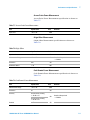
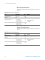
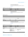
Product Regulations
EMC
Performance Criteria
IEC 61326-1:2002 / EN 61326-1:1997+A1:1998+A2:2001+A3:2003
CISPR 11:1990 / EN 55011:1990 – Group 1 Class A
IEC 61000-4-2:1995 / EN 61000-4-2:1995 (ESD 4kV CD, 8kV AD)
IEC 61000-4-3:1995 / EN 61000-4-3:1996 (3V/m, 80% AM)
IEC 61000-4-4:1995 / EN 61000-4-4:1995 (EFT 0.5kV line-line, 1kV line-earth)
IEC 61000-4-5:1995 / EN 61000-4-5:1995 (Surge 0.5kV line-line, 1kV line-earth)
IEC 61000-4-6:1996 / EN 61000-4-6:1996 (3V, 0.15~80 MHz, 80% AM, power line)
IEC 61000-4-11:1994 / EN 61000-4-11:1994 (Dips 1 cycle, 100%)
B
A
A
A
A
A
Canada: ICES-001:2004
Australia/New Zealand: AS/NZS CISPR11:2004
Safety
IEC 61010-1:2001 / EN 61010-1:2001
Canada: CAN/CSA-C22.2 No. 61010-1-04
USA: ANSI/UL 61010-1:2004
Additional Information:
The product herewith complies with the essential requirements of the Low Voltage Directive 2006/95/EC and the
EMC Directive 2004/108/EC and carries the CE Marking accordingly (European Union).
1
Performance Criteria:
A Pass - Normal operation, no effect.
B Pass - Temporary degradation, self recoverable.
C Pass - Temporary degradation, operator intervention required.
D Fail - Not recoverable, component damage.
N/A – Not applicable
Notes:
Regulatory Information for Canada
ICES/NMB-001:2004
This ISM device complies with Canadian ICES-001.
Cet appareil ISM est confomre à la norme NMB-001 du Canada.
Regulatory Information for Australia/New Zealand
This ISM device complies with Australian/New Zealand AS/NZS CISPR11:2004
N9360A Multi UE Tester CDMA2000 User Manual
Contents
Preface
1-3
Notation 1-3
Notices
1-3
Trademarks 1-4
1
Legal Information
Legal Information 1-2
Warranty 1-2
Technology Licenses
1-2
Restricted Rights Legend 1-2
Service And Support
1-3
Agilent On The Web
1-3
Agilent By Phone
1-3
Table 1-1. Agilent Call Centers and Regional Headquarters
2
Caution and Safety Requirements
Safety Information
2-2
Safety Summary
2-2
Safety Notices
2-2
Warning Label
2-2
General 2-3
When Operating The Tester
3
1-3
2-3
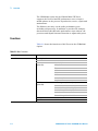
Overview
Functions 3-2
Table 3-1. Main Functions
Features
3-2
3-4
Configuration
3-5
Table 3-2. Configuration
Options
3-6
Table 3-3. Options
3-6
Accessories
3-6
Table 3-4. Accessories
N9360A Multi UE Tester CDMA2000 User Manual
3-5
3-6
i
4
Operating Procedure
Test Flow
4-2
Figure 4-1. Test Flow
4-2
Preparation for Each Test
4-3
System Requirement 4-3
Figure 4-2. Typical Test Setup of the Tester
4-3
Connection 4-3
Figure 4-3. Connecting a Printer
4-5
Figure 4-4. Connecting a USB-GPIB Converter
4-6
Test Procedure
4-7
Activating the Tester 4-7
General Operation
4-7
Figure 4-5. Display Annotation 4-7
Table 4-1. Description of the Display Annotation 4-8
Figure 4-6. Value Storage Softkeys 4-10
Figure 4-7. Memory Function 4-11
Figure 4-8. Value Storage Softkeys 4-12
Figure 4-9. Changing Magnification Softkey 4-13
Selection of System 4-14
Figure 4-10. [Top Menu] Screen 4-14
Figure 4-11. [Initial] Screen MC-1x Mode 4-15
Figure 4-12. [Initial] Screen 1xEV-DO Mode
4-16
Selection of the Function Mode on the Initial Screen
4-17
Figure 4-13. [Initial] Screen MC-1x Mode 4-17
Selection of Protocol Revision 4-18
Table 4-2. Relationship of MC-1x/1xEV-DO protocol and 3GPP2 Config
4-18
Correction 4-19
Figure 4-14. [Configuration: Test Condition (Loss)] Screen
4-22
Figure 4-15. [Configuration: Test Sequence)] Screen 4-24
Testing a Dual Band Mobile Phone by Automatic Test (MC-1x Mode) 4-25
Figure 4-16. [Initial] Screen 4-25
Figure 4-17. [Configuration: Test Condition (Loss)] Screen
4-26
Figure 4-18. [Configuration: Test Sequence1] Screen 4-27
Figure 4-19. [Configuration: Test Sequence2] Screen 4-27
Figure 4-20. [Configuration: Test Condition] Screen 4-28
Figure 4-21. [Configuration: Test Condition (Limit)] Screen 4-29
Figure 4-22. [Automatic Test: Stand-by] Value Screen (MC-1x) 4-30
Figure 4-23. [Automatic Test: Stand-by] Value Screen (MC-1x) 4-31
Testing a Dual Band Mobile Phone by Manual Test (MC-1x Mode)
4-33
Figure 4-24. [Initial] Screen 4-33
Figure 4-25. [Configuration: Test Condition (Loss)] Screen
4-34
Figure 4-26. [Configuration: Test Condition] Screen 4-35
ii
N9360A Multi UE Tester CDMA2000 User Manual
Figure 4-27. [Configuration: Test Condition (Limit)] Screen 4-36
Figure 4-28. [Manual Test: Stand-by] Screen (MC-1x)
4-37
Figure 4-29. [Manual Test: Measuring] Connection Screen (MC-1x)
4-38
Figure 4-30. [Manual Test: Measuring] Result Screen (MC-1x) 4-39
Figure 4-31. [Manual Test: Measuring] Max & Min TX Power Summary Screen
(MC-1x) 4-40
Figure 4-32. [Manual Test] Code Domain Power Result Screen (MC-1x) 4-41
Figure 4-33. [Manual Test: Stand-by] Result Screen (MC-1x) 4-42
Handoff 4-43
Emergency Call
4-44
Figure 4-34. [Manual Test: Measuring] MS Call Emergency Call Screen
(MC-1x) 4-45
Tests using 1xEV-DO Mode(Option C02)
4-46
Testing a Dual Band Mobile Phone by Automatic Test
(1xEV-DO Mode) 4-46
Figure 4-35. [Initial] Screen 4-46
Figure 4-36. [Configuration: Test Condition (Loss)] Screen
4-47
Figure 4-37. [Configuration: Test Sequence1] Screen 4-48
Figure 4-38. [Configuration: Test Sequence 2] Screen 4-48
Figure 4-39. [Configuration: Test Condition] Screen (1xEV-DO) 4-49
Figure 4-40. [Configuration: Test Condition (Limit)] Screen (1xEV-DO)
4-50
Figure 4-41. [Automatic Test: Stand-by] Value Screen
4-51
Figure 4-42. [Automatic Test: Stand-by] Result Screen 4-52
Testing a Dual Band Mobile Phone by Manual Test (1xEV-DO Mode)
4-53
Figure 4-43. [Initial] Screen 4-53
Figure 4-44. [Configuration: Test Condition (Loss)] Screen
4-54
Figure 4-45. [Configuration: Test Condition] Screen 4-55
Figure 4-46. [Configuration: Test Condition (Limit)] Screen (1xEV-DO)
4-56
Figure 4-47. [Manual Test: Stand-by] Screen (1xEV-DO) 4-57
Figure 4-48. [Manual Test: Measuring] UATI Assignment Screen
(1xEV-DO) 4-58
Figure 4-49. [Manual Test: Measuring] BS Screen (1xEV-DO) 4-59
Figure 4-50. [Manual Test: Measuring] Result Screen (1xEV-DO) 4-60
Figure 4-51. [Manual Test: Measuring] Max & Min TX Power Screen
(1xEV-DO) 4-61
Figure 4-52. [Manual Test] Code Domain Power Result Screen (1xEV-DO) 4-62
Figure 4-53. [Manual Test: Stand-by] Result Screen (1xEV-DO) 4-63
Handoff 4-64
Testing a Mobile Phone by TX Analyzer 4-65
Figure 4-54. [Initial] Screen 4-65
Figure 4-55. [Configuration: Test Condition (Loss)] Screen
4-66
Figure 4-56. [Configuration: Test Condition] Screen 4-67
Figure 4-57. [Configuration: Test Condition (Limit)] Screen 4-68
Figure 4-58. [TX Analyzer: Stand-by] Screen 4-69
N9360A Multi UE Tester CDMA2000 User Manual
iii
Figure 4-59. [TX Analyzer: Stand-by] Result Screen 4-70
Testing a Mobile Phone by Signal Generator
4-71
Figure 4-60. [Initial] Screen 4-71
Figure 4-61. [Configuration: Test Condition (Loss)] Screen
4-72
Figure 4-62. [Signal Generator] Screen 4-72
Ending a Test 4-74
Disconnecting the Mobile Phone
5
4-74
Description of Screens
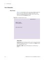
Screen Structure
5-2
Figure 5-1. Screen Structure
5-2
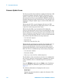
Top Menu Screen 5-3
Figure 5-2. Top Menu Structure
Figure 5-3. [Top Menu] Screen
5-3
5-4
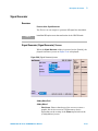
Configuration Screen 5-6
Figure 5-4. [Configuration] Screen
5-6
Figure 5-5. Part of [Configuration] screen (without Option E02)
Figure 5-6. Part of [Configuration] screen (without Option E01)
Table 5-1. Input Items on the [Configuration] Screen
5-8
Option Installation/Backup
5-10
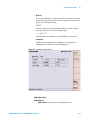
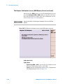
Firmware Update Screen
5-12
Figure 5-7. [Firmware Update] Screen
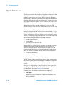
Update Flash Screen
5-16
Figure 5-8. [Update Flash] Screen
5-7
5-7
5-13
5-17
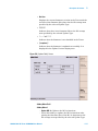
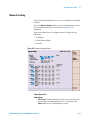
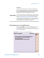
Network Setting
5-19
Figure 5-9. [Network Setting] Screen 5-19
Table 5-2. Input Items on the [Network Setting] Screen
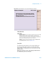
Initial Screen
5-23
Figure 5-10. [Initial] Screen 5-23
Table 5-3. Input Items on the [Initial] Screen
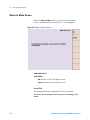
Return to Menu Screen
5-26
Figure 5-11. [Return to Menu] Screen
5-20
5-24
5-26
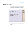
PRESET Mode Selection Screen 5-27
Figure 5-12. [PRESET Mode Selection] Screen (Menu) 5-27
Figure 5-13. [PRESET Mode Selection] Screen (cdma2000) 5-28
Automatic Test (MC-1x Mode)
5-29
Overview 5-29
Automatic RF Test
5-30
Table 5-4. Measurement Items for Automatic Test (MC-1x)
iv
5-30
N9360A Multi UE Tester CDMA2000 User Manual
Stand-by Screen
5-31
Figure 5-14. [Auto Test: Stand-by] Simplified Screen (MC-1x) 5-31
Figure 5-15. [Auto Test: Stand-by] Detailed Screen (MC-1x) 5-32
Figure 5-16. [Auto Test: Stand-by] Value Screen (MC-1x)
5-32
Table 5-5. Input Items on the [Auto Test: Stand-by] Screen (MC-1x) 5-34
Table 5-6. Items that provide information from the Mobile Phone and the Tester on
the [Automatic Test: Stand-by] Screen (MC-1x) 5-34
Measuring Screen 5-36
Figure 5-17. [Auto Test: Measuring] Simplified Screen (MC-1x)
5-36
Figure 5-18. [Auto Test: Measuring] Detailed Screen (MC-1x)
5-37
Figure 5-19. [Auto Test: Measuring] Value Screen (MC-1x) 5-37
Table 5-7. Items that provide information from the Mobile Phone and the Tester on
the [Automatic Test: Measuring] Screen (MC-1x) 5-38
Measuring Talk Screen 5-39
Figure 5-20. [Automatic Test: Measuring] Talk Simplified Screen (MC-1x) 5-39
Figure 5-21. [Automatic Test: Measuring] Talk Detailed Screen (MC-1x) 5-40
Figure 5-22. [Automatic Test: Measuring] Talk Value Screen (MC-1x)
5-40
Aborted screen 5-42
Figure 5-23. [Automatic Test: Stand-by] Aborted Simplified Screen (MC-1x)
5-42
Sequence 2 Screen 5-44
Figure 5-24. [Automatic Test: Measuring] Sequence 2 Screen (MC-1x) 5-44
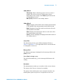
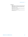
Measurement Result Display Screen 5-46
Figure 5-25. [Automatic Test: Stand-by] Result Simplified Screen (MC-1x) for
Measurement Results
5-47
Figure 5-26. [Automatic Test: Stand-by] Result Detailed Screen (MC-1x) for
Measurement Results
5-47
Figure 5-27. [Automatic Test: Stand-by] Result Value Screen (MC-1x) for
Measurement Results
5-48
Table 5-8. [Automatic Test: Stand-by] Result Screen Input Field (MC-1x)
5-49
Table 5-9. Items that provide information from the Mobile Phone and the Tester on
the [Automatic Test: Stand-by] Result Screen (MC-1x) 5-50
Manual Test (MC-1x Mode) 5-51
Overview 5-51
RF Test with Manual Test 5-52
Table 5-10. Manual Test: Measurement Items (MC-1x)
5-52
Stand-by Screen
5-53
Figure 5-28. [Manual Test: Stand-by] Screen (MC-1x)
5-53
Table 5-11. Input Items in [Manual Test: Stand-by] Screen (MC-1x) 5-55
Table 5-12. Mobile Phone Information in [Manual Test: Stand-by] Screen
(MC-1x) 5-58
Figure 5-29. [Manual Test: Measuring] MS Call Hold Screen (MC-1x)
5-60
Connection Screen 5-61
Figure 5-30. [Manual Test: Measuring] BS Call Connection Screen (MC-1x)
5-61
N9360A Multi UE Tester CDMA2000 User Manual
v
Figure 5-31. [Manual Test: Measuring] MS Call Connection Screen
(MC-1x) 5-62
Table 5-13. Input Items on [Manual Test] Connection Screen (MC-1x)
5-63
Table 5-14. Mobile Phone Information on [Manual Test: Measuring] Screen
(MC-1x) 5-65
Figure 5-32. [Manual Test: Measuring] Code Domain Power Screen
(MC-1x) 5-66
Table 5-15. Input Items on [Manual Test: Measuring] Code Domain Power
Measurement Screen (MC-1x) 5-67
Table 5-16. Mobile Phone Information on [Manual Test: Measuring] Code Domain
Power Screen (MC-1x)
5-69
Measuring Screen 5-70
Figure 5-33. [Manual Test: Measuring] BS Call Screen (MC-1x)
5-70
Figure 5-34. [Manual Test: Measuring] MS Call Screen (MC-1x) 5-71
Result Screen 5-72
Figure 5-35. [Manual Test: Stand-by] BS Call Result Screen (MC-1x)
5-72
Figure 5-36. [Manual Test: Stand-by] MS Call Result Screen (MC-1x)
5-73
Automatic Test (1xEV-DO Mode) 5-76
Overview 5-76
RF Test in Automatic Test 5-77
Table 5-17. Measurement Items for Automatic Test (1xEV-DO)
5-77
Stand-by Screen
5-79
Figure 5-37. [Automatic Test: Stand-by] Simplified Screen (1xEV-DO)
5-79
Figure 5-38. [Automatic Test: Stand-by] Detailed Screen (1xEV-DO) 5-80
Figure 5-39. [Automatic Test: Stand-by] Value Screen (1xEV-DO) 5-80
Table 5-18. Input Items on [Automatic Test: Stand-by] Screen (1xEV-DO) 5-82
Table 5-19. Mobile Phone Information on [Automatic Test: Stand-by] Screen
(1xEV-DO) 5-82
Measuring Screen 5-83
Figure 5-40. [Automatic Test: Measuring] Simplified Screen (1xEV-DO)
5-83
Figure 5-41. [Automatic Test: Measuring] Detailed Screen (1xEV-DO) 5-84
Figure 5-42. [Measuring] Numeric Value Display Screen
5-84
Table 5-20. Mobile Phone Information on [Automatic Test: Measuring] Screen
(1xEV-DO) 5-85
Aborted screen 5-86
Figure 5-43. [Automatic Test: Stand-by] Aborted Simplified Screen
(1xEV-DO) 5-86
Sequence 2 Screen 5-88
Figure 5-44. [Automatic Test: Measuring] Sequence 2 Screen (1xEV-DO)
5-88
5-89
Result Screen 5-89
Figure 5-45. [Automatic Test: Stand-by] Result Simplified Screen
(1xEV-DO) 5-90
Figure 5-46. [Automatic Test: Stand-by]Result Detailed Screen (1xEV-DO) 5-91
vi
N9360A Multi UE Tester CDMA2000 User Manual
Figure 5-47. [Automatic Test: Stand-by] Result Value Screen (1xEV-DO) 5-91
Table 5-21. Input Items on [Automatic Test: Stand-by] Result Screen
(1xEV-DO) 5-92
Table 5-22. Mobile-Phone Information on [Automatic Test: Stand-by] Result Screen
(1xEV-DO) 5-93
Manual Test (1xEV-DO Mode) 5-94
Overview 5-94
Manual RF Test
5-95
Table 5-23. Standard Test Items in 1xEV-DO Manual Test Measurement
Item
5-95
Stand-by Screen
5-96
Figure 5-48. [Manual Test: Stand-by] Screen (1xEV-DO) 5-96
Table 5-24. Entries on the [Manual Test: Stand-by] Screen (1xEV-DO) 5-98
Table 5-25. Information from a Mobile Phone displayed on the [Manual Test:
Stand-by] Screen (1xEV-DO) 5-99
Connection Screen 5-101
Figure 5-49. [Manual Test: Measuring] Connection Screen (1xEV-DO)
5-101
Table 5-26. Entries on the [Manual Test: Measuring] Connection Screen
(1xEV-DO) 5-102
Table 5-27. Mobile Phone Information on the [Manual Test: Measuring] Screen
(1xEV-DO) 5-104
Code Domain Power Measuring Screen 5-105
Figure 5-50. [Manual Test] Code Domain Power Screen (3GPP2 Config is set to 1
or 2) (1xEV-DO)
5-105
Figure 5-51. [Manual Test] Code Domain Power Screen ("3GPP2 Config" is set to 3
or 4) (1xEV-DO)
5-106
Table 5-28. Entries on the [Manual Test: Measuring] Screen for Code Domain
Power Measurement (MC-1x)
5-107
Table 5-29. Mobile Phone Information on the Code Domain Power Screen
(MC-1x) 5-108
Measuring Screen 5-109
Figure 5-52. [Manual Test: Measuring] Measuring Screen (1xEV-DO) 5-109
Table 5-30. Mobile Phone Information on the [Manual Test: Measuring] Screen
(1xEV-DO) 5-110
Result Screen 5-111
Figure 5-53. [Manual Test: Stand-by] Result Screen (1xEV-DO) 5-111
TX Analyzer 5-114
Overview 5-114
Radio Performance Test in TX Analyzer
5-115
Table 5-31. TX Analyzer Measurement Item
5-115
Stand-by Screen
5-116
Figure 5-54. [TX Analyzer: Stand-by] Screen 5-116
Table 5-32. Entries on the [TX Analyzer: Stand-by] Screen 5-117
Table 5-33. TX Analyzer: Stand-by] Screen Information
5-119
N9360A Multi UE Tester CDMA2000 User Manual
vii
Measuring Screen 5-120
Figure 5-55. [TX Analyzer: Measuring] Screen 5-120
Result Screen 5-121
Figure 5-56. [TX Analyzer: Stand-by] Result Screen 5-121
Code Domain Power Measuring Screen (MC-1x Mode) 5-123
Figure 5-57. [TX Analyzer: Stand-by] Code Power Screen (MC-1x Mode)
5-123
Table 5-34. Entries on the [TX Analyzer: Stand-by] Code Domain Power Screen
(MC-1x) 5-124
Table 5-35. Mobile Phone Information on the [TX Analyzer: Stand-by] Code Domain
Power Screen (MC-1x)
5-125
Code Domain Power Measuring Screen (1xEV-DO Mode)
5-126
Figure 5-58. Code Power Screen (If "3GPP2 Config" is set to 1 or 2)
(1xEV-DO) 5-127
Figure 5-59. Code Power Screen (If "3GGP2 Config" is set to 3 or 4)
(1xEV-DO) 5-127
Table 5-36. Entries on the [TX Analyzer: Stand-by] Code Domain Power Screen
(1xEV-DO) 5-128
Table 5-37. Mobile Phone Information on the [TX Analyzer] Code Domain Power
Screen (1xEV-DO) 5-130
Signal Generator 5-131
Overview 5-131
Signal Generator (Signal Generator) Screen 5-131
Figure 5-60. [Signal Generator] screen 5-131
Table 5-38. Input field of the [Signal Generator] screen
5-132
Table 5-39. [Manual Test: Measuring] Mobile Phone information on the 1xEV-DO
mode connection screen
5-133
Modulation Waveform 5-135
Figure 5-61. Waveform (Modulation is set to Off) 5-135
Figure 5-62. Waveform (Modulation is set to AM Modulation 1)
Figure 5-63. Waveform (Modulation is set to AM Modulation 2)
5-136
5-136
Configuration
5-137
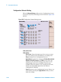
Configuration Screen 5-137
Figure 5-64. [Configuration] screen
5-138
Figure 5-65. Part of the [Configuration] Screen (without Option E02)
Figure 5-66. Part of the [Configuration] Screen (without Option E01)
Table 5-40. Input items on the [Configuration] Screen
5-139
Table 5-41. Display items on the [Configuration] screen
5-141
Configuration: Test Sequence Screen
5-142
Figure 5-67. [Configuration: Test Sequence] screen (MC-1x)
5-142
Table 5-42. Test flow item settings (MC-1x) 5-143
Table 5-43. Input items on the [Configuration: Test Sequence] Screen
(MC-1x) 5-150
viii
5-139
5-139
N9360A Multi UE Tester CDMA2000 User Manual
Table 5-44. Input items on the [Configuration: Test Sequence] Screen
(MC-1x) 5-152
Figure 5-68. [Configuration: Test Sequence] Screen (3GPP2 Config is set to 1 or 2
(1xEV-DO Rel. 0)) 5-153
Figure 5-69. [Configuration: Test Sequence] Screen (3GPP2 Config is set to 3 or 4
(1xEV-DO Rev. A)) 5-154
Table 5-45. Combination of test item settings (1xEV-DO) 5-155
Table 5-46. Input items on the [Configuration: Test Sequence] Screen
(1xEV-DO) 5-155
Table 5-47. Measurement items on the [Configuration: Test Sequence] Screen
(1xEV-DO) 5-157
Configuration: Test Condition Screen
5-158
Figure 5-70. [Configuration: Test Condition] Screen (MC-1x) 5-158
Table 5-48. [Configuration: Test Condition] Screen Input Field (MC-1x) 5-159
Figure 5-71. [Configuration: Test Condition] Screen (1xEV-DO) 5-162
Table 5-49. [Configuration: Test Condition] Screen Input Field (1xEV-DO) 5-163
Configuration: Test Condition (Loss) Screen
5-165
Figure 5-72. [Configuration: Test Condition (Loss)] screen
5-165
Table 5-50. Input field on the [Configuration: Test Condition (Loss)]
screen 5-166
Configuration: Test Condition (Limit) Screen
5-166
Configuration: Test Condition (Limit)Screen (MC-1x)
5-166
Figure 5-73. [Configuration: Test Condition (Limit)] Screen (MC-1x) 5-167
Table 5-51. [Configuration: Test Condition (Limit)] Measurement Item
(MC-1x) 5-168
Configuration: Test Condition (Limit) Screen (1xEV-DO)
5-169
Figure 5-74. [Configuration: Test Condition (Limit)] Screen (1xEV-DO)
5-169
Table 5-52. [Configuration: Test Condition (Limit)] Measurement Item
(1xEV-DO) 5-170
Configuration: File Management
5-171
Figure 5-75. [Configuration: File Management] screen 5-172
Table 5-53. Error messages of the file management
5-173
Saving a Test Setup File 5-174
Figure 5-76. [Configuration: File Management] Save-1 Screen
5-174
Figure 5-77. [Configuration: File Management] Save-2 screen
5-175
Figure 5-78. [Configuration: File Management] Save-3 screen
5-176
Figure 5-79. [Configuration: File Management] Save-4 screen
5-177
Figure 5-80. [Configuration: File Management] Save-5 screen
5-178
Figure 5-81. [Configuration: File Management] Overwrite Screen 5-179
Calling up a test setup file 5-180
Figure 5-82. [Configuration: File Management] Call up-1 screen 5-180
Figure 5-83. [Configuration: File Management] Call up-2 screen 5-181
Figure 5-84. [Configuration: File Management] Call up-3 screen 5-182
Deleting a Test Setup File 5-182
N9360A Multi UE Tester CDMA2000 User Manual
ix
Figure 5-85. [Configuration: File Management] Delete-1 screen 5-183
Figure 5-86. [Configuration: File Management] Delete-2 screen 5-184
Figure 5-87. [Configuration: File Management] Delete-3 screen 5-185
File Replace Confirmation screen (when HDD selected)
5-186
Figure 5-88. File Replace Confirmation screen (HDD) 5-186
File Replace Confirmation screen (USB Memory Device is selected) 5-188
Figure 5-89. File Replace Confirmation screen (when USB memory
selected) 5-188
Undo Confirmation screen (when HDD selected) 5-189
Figure 5-90. Undo Confirmation Screen (when HDD selected)
5-189
Undo Confirmation screen (when USB memory selected) 5-190
Figure 5-91. Undo Confirmation screen (when USB memory selected) 5-191
Configuration: Network Setting
5-192
Figure 5-92. [Configuration: Network Setting] screen 5-192
Table 5-54. [Configuration: Network Setting] screen
5-193
6
Troubleshooting
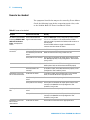
Items to be checked
6-2
Table 6-1. Items to be checked
6-2
Error Information
6-4
Error Screen
6-4
Figure 6-1. An example of [Error] screen
Table 6-2. Alarm Notification Error Code
Table 6-3. UI Timer Error Code
6-6
7
6-4
6-5
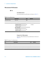
Performance and Specifications
Measurement Performance 7-2
MC-1x
7-2
Table 7-1. Power Measurement
7-2
Table 7-2. Frequency Error Measurement
7-2
Table 7-3. Waveform Quality (Rho/Multi-Code Rho) measurement
Table 7-4. Time Offset measurement 7-3
Table 7-5. Maximum TX Power Measurement
7-4
Table 7-6. Minimum TX Power Measurement 7-4
Table 7-7. Access Probe Power Measurement 7-5
Table 7-8. Origin Offset
7-5
Table 7-9. Code Domain Power Measurement
7-5
1xEV-DO
7-6
Table 7-10. Power Measurement
7-6
Table 7-11. Frequency Error Measurement
7-6
Table 7-12. Waveform Quality (Rho/Multi-Code Rho) measurement
Table 7-13. Time Offset Measurement
7-7
Table 7-14. Maximum TX Power Measurement
7-8
x
7-3
7-7
N9360A Multi UE Tester CDMA2000 User Manual
Table 7-15. Minimum TX Power Measurement
Table 7-16. Access Probe Power Measurement
Table 7-17. Origin Offset
7-9
Table 7-18. Code Domain Power Measurement
A
7-8
7-9
7-9
Appendix A Input Items and Allowable Options or Ranges
Table A-1. Input fields and allowance choices or ranges
A-2
Table A-2. Relation between Radio Config and Service Option
A-20
B
Appendix B General information on cdma2000 system
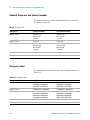
Channel frequency and channel number
Table B-1. RF channel B-2
Frequency band
B-2
Table B-2. Frequency band
B-2
B-2
S/R frequency interval B-3
Table B-3. S/R frequency interval B-3
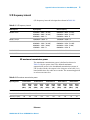
UE maximum transmission power B-3
Table B-4. UE maximum transmission power
C
Appendix C N9360A-A02 Antenna Coupler
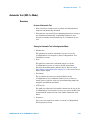
Introduction
Specifications
C-2
C-2
Operating the Antenna Coupler
D
B-3
C-3
Appendix D Parameters of physical channels
Table D-5. Details of the modulation set value in TX Analyzer and Signal
Generator
D-2
Table 5. Details of the modulation set value in TX Analyzer and Signal
Generator
D-4
E
Appendix E Softkey Menu Multi-language
Introduction E-2
How to switch the Softkey Menu
N9360A Multi UE Tester CDMA2000 User Manual
E-2
xi
xii
N9360A Multi UE Tester CDMA2000 User Manual
Agilent N9360A Multi UE Tester
CDMA2000 User Manual
1
Legal Information
Warranty 1-2
Technology Licenses 1-2
Restricted Rights Legend 1-2
Service And Support 1-3
Agilent On The Web 1-3
Agilent By Phone 1-3
Agilent Technologies
1-1
1
Legal Information
Legal Information
Warranty
The material contained in this document is provided “as is,” and
is subject to being changed, without notice, in future editions.
Further, to the maximum extent permitted by applicable law,
Agilent disclaims all warranties, either express or implied, with
regard to this manual and any information contained herein,
including but not limited to the implied warranties of
merchantability and fitness for a particular purpose. Agilent
shall not be liable for errors or for incidental or consequential
damages in connection with the furnishing, use, or performance
of this document or of any information contained herein.
Should Agilent and the user have a separate written agreement
with warranty terms covering the material in this document
that conflict with these terms, the warranty terms in the
separate agreement shall control.
Technology Licenses
The hardware and/or software described in this document are
furnished under a license and may be used or copied only in
accordance with the terms of such license.
Restricted Rights Legend
If software is for use in the performance of a U.S. Government
prime contract or subcontract, Software is delivered and
licensed as “Commercial computer software” as defined in
DFAR 252.227-7014 (June 1995), or as a “commercial item” as
defined in FAR 2.101(a) or as “Restricted computer software” as
defined in FAR 52.227-19 (June 1987) or any equivalent agency
regulation or contract clause. Use, duplication or disclosure of
Software is subject to Agilent Technologies’ standard
commercial license terms, and non-DOD Departments and
Agencies of the U.S. Government will receive no greater than
Restricted Rights as defined in FAR 52.227-19(c)(1-2)(June
1987). U.S. Government users will receive no greater than
Limited Rights as defined in FAR 52.227-14 (June 1987) or
DFAR 252.227-7015 (b)(2)(November 1995), as applicable in any
technical data.
1-2
N9360A Multi UE Tester CDMA2000 User Manual
Legal Information
1
Service And Support
Any adjustment, maintenance, or repair of this product must be
performed by qualified personnel. Contact your customer
engineer through your local Agilent Technologies Service
Center.
Agilent On The Web
You can find information about technical and professional
services, product support, and equipment repair and service on
the Web: http://www.agilent.com/
Double-click the link to Test & Measurement. Select your country
from the drop-down menus. The Web page that appears next has
contact information specific for your country
Agilent By Phone
If you do not have access to the Internet, call one of the
numbers in Table 1-1.
Table 1-1 Agilent Call Centers and Regional Headquarters
United States and Canada:
Test and Measurement Call Center
(800) 452 4844 (toll-free in US)
Europe:
(41 22) 780 8111
Japan:
Measurement Assistance Center
(81) 0426 56 7832
Latin America:
305 269 7548
Asia-Pacific:
(85 22) 599 7777
Manufacturing Address
Agilent Technologies Microwave Products (Malaysia) Sdn. Bhd.
Bayan Lepas Free Industrial Zone,
11900 Penang,
Malaysia.
N9360A Multi UE Tester CDMA2000 User Manual
1-3
1
Legal Information
THIS PAGE IS INTENTIONALLY LEFT BLANK
1-4
N9360A Multi UE Tester CDMA2000 User Manual
Agilent N9360A Multi UE Tester
CDMA2000 User Manual
2
Caution and Safety Requirements
Safety Summary 2-2
Safety Notices 2-2
Warning Label 2-2
General 2-3
When Operating The Tester 2-3
Agilent Technologies
2-1
2
Caution and Safety Requirements
Safety Information
Safety Summary
The following general safety precautions must be observed
during all phases of operation of this instrument. Failure to
comply with these precautions or with specific warnings
elsewhere in this manual violates safety standards of design,
manufacture, and intended use of the instrument. Agilent
Technologies, Inc. assumes no liability for the customer's failure
to comply with these requirements.
Safety Notices
CAUTION
A CAUTION notice denotes a hazard. It calls attention to an
operating procedure, practice, or the like, that, if not correctly
performed or adhered to, could result in damage to the product or
loss of important data. Do not proceed beyond a CAUTION notice
until the indicated conditions are fully understood and met.
WA RNING
A WARNING notice denotes a hazard. It calls attention to an operating
procedure, practice, or the like that, if not correctly performed or
adhered to, could result in personal injury or death. Do not proceed
beyond a WARNING notice until the indicated conditions are fully
understood and met.
Warning Label
A warning label is stuck on the front panel of the Tester.
Do not remove, damage or modify the warning label.
2-2
N9360A Multi UE Tester CDMA2000 User Manual
Caution and Safety Requirements
2
General
WA RNING
The protection provided by the Agilent N9360A Tester may be
impaired if the tester is used in a manner not specified by Agilent
or the instructions on the display are not followed.
WA RNING
DO NOT INSTRUMENT COVERS. Operating personnel must not
remove any instrument covers. Component replacement and
internal adjustments must be made only by qualified service
personnel. Products that appear damaged or defective should be
made inoperative and secured against unintended operation until
they can be repaired by a qualified service personnel.
When Operating The Tester
CAUTION
Make sure that the input signal level does not exceed the maximum level
allowed. Tester failure may result otherwise.
CAUTION
Do not turn off the Line switch on the rear panel of the Tester while the
LINE LED on the front panel of the Tester is lit in green. Otherwise, Tester
failure may occur.
N9360A Multi UE Tester CDMA2000 User Manual
2-3
2
Caution and Safety Requirements
THIS PAGE IS INTENTIONALLY LEFT BLANK.
2-4
N9360A Multi UE Tester CDMA2000 User Manual
Agilent N9360A Multi UE Tester
CDMA2000 User Manual
3
Overview
Functions 3-2
Features 3-4
Configuration 3-5
Options 3-6
Accessories 3-6
This chapter outlines the feature of the CDMA2000 Option. For
functions of the GSM Option, refer to the N9360A Multi UE
Tester GSM User Manual, and for functions of the W-CDMA
Option, refer to the N9360A Multi UE Tester W-CDMA User
Manual.
Agilent Technologies
3-1
3
Overview
The CDMA2000 Option for the N9360A Multi UE Tester
supports the Protocol and RF performance tests to inspect
mobile phones in the process of production, service, repair and
maintenance.
The N9360A can carry out the radio performance tests
including call processes. In addition, it provides TX Analyzer
function which offer RF radio performance tests without call
processes and Signal Generator function to adjust radio parts.
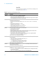
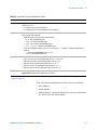
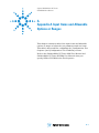
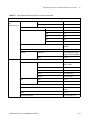
Functions
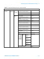
Table 3-1 shows the functions of this Tester in the CDMA2000
Option.
Table 3-1 Main Functions
Option
Function
cdma2000
Band: 0, 1, 3, 4, 6
Protocol Test
MC-1x
(Option C01)
Location Update
MS Call
Talk
MS Release
BS Call
BS Release
Softer Handoff
Hard Handoff
1xEV-DO
(Option C02)
UATI Assignment (Session Open)
BS Call
Connection Close (Initiated by AN)
Session Close (Initiated by AN)
Softer Handoff
Channel Change (Hard Handoff)
TX Analyzer
Signal Generator
3-2
AM Modulation
N9360A Multi UE Tester CDMA2000 User Manual
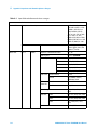
3
Overview
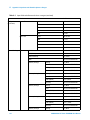
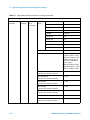
Table 3-1 Main Functions
Option
Function
cdma2000 (continued)
Radio Performance Test
MC-1x
(Option C01)
TX Power Measurement
Frequency Error Measurement
Rho/Multi-code Rho Measurement
Origin Offset Measurement
Maximum TX Power Measurement
Minimum TX Power Measurement
Time Offset Measurement
Sensitivity/FER Measurement, Sensitivity/TDSO
FER Measurement 1
Code Domain Power Measurement
TX Power 2
Pilot 2
Traffic (Fundamental) 2
Max Inactive Channel 2
Access Probe Power Measurement
Inner Loop Power Control Measurement
ILP (Down)
ILP (Up)
1xEV-DO
(Option C02)
TX Power Measurement
Frequency Error Measurement
Waveform Quality (Multi-Code Rho) Measurement
Packet Error Rate (PER) Measurement
Maximum TX Power Measurement
Minimum TX Power Measurement
Time Offset Measurement
Code Domain Power Measurement
TX Power
Pilot
RRI
DRC
ACK
DSC 3
Data
Max Inactive Channel
Access probe Power
Inner Loop Power Control Measurement
ILP (Down)
ILP (Up)
N9360A Multi UE Tester CDMA2000 User Manual
3-3
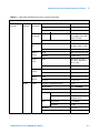
3
Overview
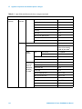
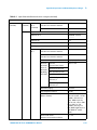
Table 3-1 Main Functions
Option
Function
Remote Control
Ethernet
Serial (Option E01)
GP-IB (Option E02)
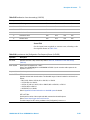
1. The measurement is valid only when the Radio Configuration is set to F3R3, F4R3 and
F5R4 and the Service Option is set to 32.
2. The measurement is valid only when the Radio Configuration is set to F3R3, F4R3 and
F5R4.
3. The measurement is valid only when the 3GPP2 Config is set to 3 or 4 (1xEV-DO Rev.
A).
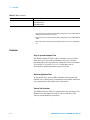
Features
Easy-to-operate Automatic Test
The N9360A Multi UE Tester offers automatic test procedure
from protocol to the radio performance tests are executed
automatically with easy operation. Each test item in Automatic
Test can be set to either On or Off. Testing time can be
shortened by eliminating unnecessary test items.
Reducing Operation Time
In Automatic Test, preset traffic channels are automatically
handed over. Consequently, restarting for each traffic channel is
not required and testing time can be shortened.
Various Test Functions
The N9360A Tester, which is equipped with the Automatic Test,
Manual Test, and Signal Generator, can be used for a wide
variety of measurement operations.
3-4
N9360A Multi UE Tester CDMA2000 User Manual
3
Overview
Extensive Interface Options
The N9360A Tester offers various interface options including
Ethernet, USB, GP-IB (Option E02) and Serial (Option E01). The
USB ports are offered to connect a printer, a USB-GPIB
converter (Option E02), or a USB memory device for firmware
update or parameter saving/recalling. Ethernet, GP-IB, and
Serial are used for remote control.
External Control Function (Remote Control)
Remote control is available using Ethernet, USB-GPIB converter
(Option E02) or Serial (Option E01). Each interface port uses
the same commands. User can select the most appropriate
option from these selections.
5-band Handover
Handover is executed through all channels of five bands while
being connected. This function is available if the mobile phone
supports the bands and channels to be hand overed.
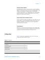
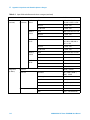
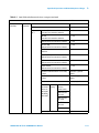
Configuration
Table 3-2 shows the configuration of the Tester. Check the
components before using the Tester.
Table 3-2 Configuration
Item name
Type
Quantity
Remarks
cdma2000 Option
C00, C01, C02
1
Installed on the Tester
User Manual
1
Programming Manual
1
Quick Reference
1
Installation Guide
1
Inspection Data
1
Certificate of Calibration
—
N9360A Multi UE Tester CDMA2000 User Manual
1
3-5
3
Overview
Options
Table 3-3 shows the options of the Tester. For the specification
of the options, contact the Agilent Sales Department or an
approved distributor.
Table 3-3 Options
Item Name
Type
Remarks
CDMA2000 Band15:AWS
C03
Band15: Advanced Wireless Services
Serial Port
E01
DSub 9-pin male connector
USB-GPIB Converter
E02
Use a USB interface IEEE 24 pin
connector (Amphenol)
cdma2000 PoST 1
E05
PoST software for cdma2000
1. Post (Point of Service Test) is software to control the Tester with PCs.
Accessories
Table 3-4 shows the accessories of the Tester. For the
specification of the accessories, contact the Agilent Sales
Department or an approved distributor.
Table 3-4 Accessories
Item Name
Type
Remarks
Antenna Coupler
N9360A-A02
Frequency Range:
824 to 1990MHz
Coupling Factor:
15dB (at 824 to 960 MHz)
13dB (at 1710 to 1880 MHz)
11dB (at 1880 to 1990 MHz)
Shield Case
N9360A-S01
Built-in PCB antenna-type
Frequency Range: 800 to 2000 MHz
3-6
N9360A Multi UE Tester CDMA2000 User Manual
Overview
3
THIS PAGE IS INTENTIONALLY LEFT BLANK.
N9360A Multi UE Tester CDMA2000 User Manual
3-7
3
3-8
Overview
N9360A Multi UE Tester CDMA2000 User Manual
Agilent N9360A Multi UE Tester
CDMA2000 User Manual
4
Operating Procedure
Test Flow 4-2
Preparation for Each Test
Test Procedure 4-7
Ending a Test 4-74
4-3
This chapter describes the preparations required and the
operating procedures before starting the test of the CDMA
Mobile Unit. For the testing method of the GSM Mobile Unit,
refer to the N9360A Multisystem UE Tester GSM Option User's
Guide and for the testing method of the W-CDMA Mobile Unit,
refer to the N9360A Multi UE Tester W-CDMA Option User's
Guide.
Agilent Technologies
4-1
4
Operating Procedure
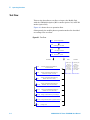
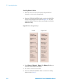
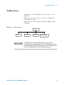
Test Flow
This section describes a test flow to inspect the Mobile Unit
with the CDMA2000 Option (MC-1x mode: Option C01, 1xEV-DO
mode: Option C02).
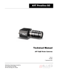
Figure 4-1 shows the test operation flow.
Subsequently, the mobile phone operation method is described
according to the test flow.
Figure 4-1 Test Flow
2.2.1 System Requirement
2.2.2 Installing the Test SIM
2.3.1
Activating the Tester
2.3.3
Selection of System
cdma2000
GSM
2.3.4
Selection of the Function Mode on
the Initial Screen
2.3.6
Testing a Dual Band Mobile Phone by
Automatic Test (MC-1x mode)
2.3.7
Testing a Dual Band Mobile Phone by
Manual Test (MC-1x mode)
2.3.10
Testing a Dual Band Mobile Phone by
Automatic Test (1xEV-DO mode)
2.3.11
GSM System
Refer to
the NJZ-2000
Multisystem
UE Tester
GSM Option
User's Guide
WCDMA
W-CDMA System
Refer to
the NJZ-2000
Multisystem
UE Tester
W-CDMA Option
User's Guide
Testing a Dual Band Mobile Phone by
Manual Test (1xEV-DO mode)
2.3.13 Testing a Mobile Phone by TX Analyzer
2.3.14 Testing a Mobile Phone by Signal Generator
2.4
4-2
Ending a Test
N9360A Multi UE Tester CDMA2000 User Manual
Operating Procedure
4
Preparation for Each Test
CAUTION
Make sure that the input signal level does not exceed the maximum
level allowed. Otherwise, an accident or Tester failure may occur.
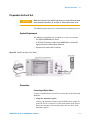
The following procedures are required before starting each test.
System Requirement
The following equipment are required to set up a test system:
• The Agilent N9360A Multi UE Tester.
• An RF cable, RF antenna coupler (type N9360A-A02) to connect RF
signals from/to the mobile phone under test.
• A printer and a printer cable if required.
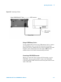
Figure 4-2 Typical Test Setup of the Tester
Connection
Connecting a Mobile Phone
Connect a mobile phone to the Tester using any of the following
methods:
1 Using the Antenna Coupler
Connect the Antenna Coupler (type N9360A-A02) connector
to the RF IN/OUT connector on the front panel of the Tester.
Insert the antenna of the mobile phone into the hole of the
Antenna Coupler.
N9360A Multi UE Tester CDMA2000 User Manual
4-3
4
Operating Procedure
2 Using a User-Supplied RF Cable
If you have a cable which connects between the RF port of
the mobile phone and the RF IN/OUT connector of the Tester,
use it instead of the Antenna Coupler.
3 Using the Shield Case
Connect the ANTENNA COUPLER IN/OUT connector of the
shield case (type N9360A-S01) to the RF IN/OUT connector
on the front panel of the Tester. Place the mobile phone on
the antenna coupler board inside the shield case using the
horizontal and vertical holders.
Connecting a Printer
To print screen hard copies, if required, connect a printer to the
Tester as follows using an appropriate interface cable between
the USB connector on the rear panel of the Tester and the USB
interface connector of the printer. Use the recommended
printer shown below. Also, refer to the manual of the printer for
operating the printer.
Recommended printer (operation confirmed by Agilent):
EPSON PM-G800
4-4
N9360A Multi UE Tester CDMA2000 User Manual
Operating Procedure
4
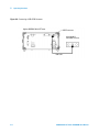
Figure 4-3 Connecting a Printer
Agilent N9360A Multi UE Tester
USB Connector
Printer
USB Interface
Connector
Printer Cable
Using a USB Memory Device
To save graphic files of screen in a USB memory device, connect
the USB memory device to the USB connector on the front
panel of the Tester. Graphic files are saved in Portable Network
Graphics (PNG) format and with a file name: COPY and the
number from 00 to 99 which automatically increases.
Connecting a USB-GPIB Converter
When you control the Tester using a GP-IB interface, use the
USB-GPIB converter (Option E02). Connect the USB-GPIB
converter and the USB connector on the rear panel of the Tester
with a USB cable.
N9360A Multi UE Tester CDMA2000 User Manual
4-5
4
Operating Procedure
Figure 4-4 Connecting a USB-GPIB Converter
Agilent N9360A Multi UE Tester
USB Connector
GP-IB (USB) FL
USB-GPIB Converter
USB Cable
4-6
N9360A Multi UE Tester CDMA2000 User Manual
4
Operating Procedure
Test Procedure
Activating the Tester
To activate the Tester, turn on the LINE switch on the rear
panel of the Tester and press the LINE switch on the front
panel.
NOTE
Provide warm up of 30 minutes or more to ensure correct measurement.
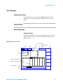
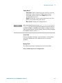
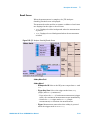
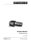
General Operation
Display Annotation
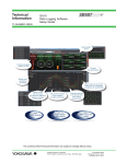
Depending on functions and test situations, there are several
types of screen. Figure 4-5 shows the common areas on the
typical screen.
Figure 4-5 Display Annotation
a) Test Flow
b) Test Results
①
Automatic
Test
②
Stand-by
③
④
2037/12/31 23:59
⑤
c) Measurement Item
d) Measurement Result
e) Input Field
⑥
Press [Start] to begin a test.
N9360A Multi UE Tester CDMA2000 User Manual
4-7
4
Operating Procedure
Table 4-1 Description of the Display Annotation
No.
Name
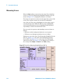
Description
1
Function Mode Field
The current function mode, for example, Automatic Test, Manual Test, TX
Analyzer and Configuration, is displayed in this field.
2
Status Display Field
The current operation status, for example, Stand-by, Measuring, Test
Sequence and Test Condition, is displayed in this field.
3
Date/Time Field
The current date and time are displayed in this field.
4
Softkey Menu Field
The softkey labels are displayed in this field. Each label defines the function of
the corresponding softkey immediately next to the right of the label.
5
Screen Field
A variety of information is displayed in this field depending on the operation
status. For example, in Automatic Test, the following information is displayed
in this field.
a) Test Flow: Location Update, MS Call, BS Call, etc.
b) Test results: P (pass) or F (fail).
c) Measurement Items: Peak TX Power, Frequency Error, etc.
d) Measurement Results: Pass/Fail or values.
e) Input field: Highlighted fields.
6
Message Field
Operation message for test flow steps are displayed in this field.
In this field, the word surrounded by bracket ''()'' denotes the softkey.
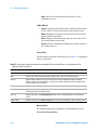
Selecting Items and Changing Parameters
Depending on the function modes, the Tester has a number of
input fields to be specified or defined to configure a test flow,
test sequence and test condition. The allowable ranges for those
input fields depending on the radio systems are explained in
this manual. For a quick overview, refer to Appendix A Input
Items and Allowable Options or Ranges on page A-1.
Selecting an Input Field and Specifying a Value
All input fields to be specified are highlighted and the circular
cursor is shown next to one of them.
To start, first select an input field and then specify a value to
the input field by the following procedure:
1 Rotate the CURSOR CONTROL knob clockwise to move the
cursor downward or right, or rotate it counterclockwise to
4-8
N9360A Multi UE Tester CDMA2000 User Manual
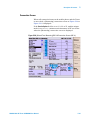
Operating Procedure
4
move it upward or left, and place it next to the input field
you want to change.
2 Press the CURSOR CONTROL knob once. The highlighted
input field changes to normal display and circular cursor
changes to a triangular one.
3 Rotate the CURSOR CONTROL knob clockwise or
counterclockwise to find the values to specify for it.
4 Press the CURSOR CONTROL knob to enter the desired value
in the input field. The input field is highlighted again and the
triangular cursor returns to the circular one.
N9360A Multi UE Tester CDMA2000 User Manual
4-9
4
Operating Procedure
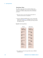
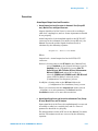
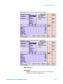
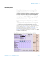
Storing Numeric Values
For numeric input fields such as channel numbers and
relevancies of amplitude, you can store up to four numeric
values into the memory softkey menus with the following
procedure:
1 Move the cursor to one of the numeric input fields of
channels and relevancies of amplitude.
2 Press the CURSOR CONTROL knob to select the field. The
softkey menu as Figure 4-6 is displayed on the screen. The
four memory softkeys show the values previously stored in
the memories if any.
Figure 4-6 Value Storage Softkeys
Channel
Output Level
3 Set a numeric value in the input field with the CURSOR
CONTROL knob.
4-10
N9360A Multi UE Tester CDMA2000 User Manual
4
Operating Procedure
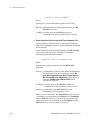
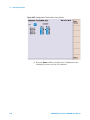
4 Press the Store Value to Memory >> softkey. The softkey menu
including Memory 1, Memory 2, Memory 3 and Memory 4
softkeys as shown in Figure 4-7.
Figure 4-7 Memory Function
5 Press one of the memory softkeys from Memory 1 to Memory 4
where you desire to store that value.
6 The memory softkey menu returns to the state in step 2
showing the value newly stored.
7 Press the CURSOR CONTROL knob to set the value into the
field. The softkey menu returns to that of step 1.
8 Repeat the procedure from step 1 to step 7, if required.
N9360A Multi UE Tester CDMA2000 User Manual
4-11
4
Operating Procedure
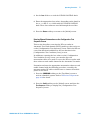
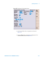
Recalling Numeric Values
1 Move the cursor to one of the numeric input fields of
channels or relevancies of amplitude.
2 Press the CURSOR CONTROL knob to select the field. The
softkey menu displayed as shown in Figure 4-8. The four
memory softkeys show the values previously stored in the
memories if any.
Figure 4-8 Value Storage Softkeys
Channel
Output Level
3 Press Memory 1, Memory 2, Memory 3 or Memory 4 softkey to
enter the stored value to the field.
4 The value is entered to the field.
5 Press the CURSOR CONTROL knob to return the softkey
menu to that of step 1.
4-12
N9360A Multi UE Tester CDMA2000 User Manual
4
Operating Procedure
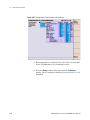
Changing Magnification Softkey
Press the CURSOR CONTROL knob to select a numeric input
field, such as channels and relevancies of amplitude. A changing
magnification softkey as in Figure 4-9 is displayed with memory
softkeys. A selected magnification is underlined.
Figure 4-9 Changing Magnification Softkey
Pressing this softkey changes the multiplier from 1 to 1000.
Rotating the CURSOR CONTROL knob clockwise changes the
numeric value in the field by an increment, and
counterclockwise changes the value by a decrement. The
following multiplies are variable.
• ×1: Increment or decrement by 1.
• ×10: Increment or decrement by 10.
• ×100: Increment or decrement by 100.
• ×1000: Increment or decrement by 1000.
N9360A Multi UE Tester CDMA2000 User Manual
4-13
4
Operating Procedure
Selection of System
On this screen, select a system from GSM, W-CDMA or
cdma2000.
NOTE
This N9360A CDMA2000 User Manual describes only the cdma2000
system. Refer to the N9360A GSM User Manual for GSM system and the
N9360A W-CDMA User Manual for W-CDMA system.
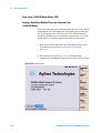
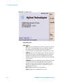
1 Turn on the Tester. The [Top Menu] screen is displayed as
Figure 4-10.
Figure 4-10 [Top Menu] Screen
4-14
N9360A Multi UE Tester CDMA2000 User Manual
4
Operating Procedure
2 Press the CDMA2000 softkey to select the cdma2000 system.
The [Initial] screen for cdma2000 is displayed after the
Tester completes its initialization and self-test
routine.Figure 4-11 shows the [Initial] screen of the MC-1x
mode. When shifting the 1xEV-DO mode, press the CDMA
Mode>>, 1xEV-DO softkey. (See Figure 4-12) Or, specify the
CDMA Mode field on the [Configuration: Test Condition]
screen obtained to press the Config and Test Condition
softkeys.
Figure 4-11 [Initial] Screen MC-1x Mode
N9360A Multi UE Tester CDMA2000 User Manual
4-15
4
Operating Procedure
Figure 4-12 [Initial] Screen 1xEV-DO Mode
NOTE
When the Autoboot function is set to FUNC GSM, FUNC WCDMA or, FUNC
CDMA2000, the Tester will automatically select the GSM, W-CDMA or
cdma2000 system mode if no softkey is pressed within the specified time
(10 to 60 seconds). When the Tester is shipped, the AutoBoot function is
set to None.
4-16
N9360A Multi UE Tester CDMA2000 User Manual
4
Operating Procedure
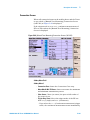
Selection of the Function Mode on the Initial Screen
Press one of the softkeys to select a function mode.
Figure 4-13 [Initial] Screen MC-1x Mode
Softkey Menu Field
Softkey menu 1
• Automatic Test: Starts the Automatic Test. Refer to Testing
a Dual Band Mobile Phone by Automatic Test (MC-1x
Mode) and Tests using 1xEV-DO Mode(Option C02).
• Manual Test: Starts the Manual Test. Refer to Testing a Dual
Band Mobile Phone by Manual Test (MC-1x Mode), Testing
a Dual Band Mobile Phone by Manual Test (1xEV-DO Mode).
• TX Analyzer: Displays the [TX Analyzer] screen. Refer to TX
Analyzer.
• Signal Generator: Displays the Signal Generator. Refer to
Signal Generator.
• CDMA Mode>>: Shifts the system to CDMA Mode. The Sub
Softkey is displayed on the screen and you can change the
mode to MC-1x or 1xEV-DO when this softkey is pressed.
The C02 option is required to install.
• More (1 of 2): Displays the softkey menu 2.
N9360A Multi UE Tester CDMA2000 User Manual
4-17
4
Operating Procedure
• Config: Displays the [Configuration] screen to set
parameters. Refer to Configuration.
Softkey menu 2
• Print Screen: Prints the screen hard-copy or stores the
screen image in the USB memory device, according to the
Printer field setting on the [Configuration] screen.
• Return to Menu: This softkey is not for selecting a function
mode. The screen returns to the [Top Menu] screen when
this softkey is pressed. Refer to Return to Menu Screen for
detail.
• More (2 of 2): Returns to the Softkey Menu 1.
Softkey menu 3
• MC-1x: Changes to the MC-1x mode of the CDMA Mode. The
C01 option is required.
• 1xEV-DO: Changes to the 1xEV-DO mode of the CDMA Mode.
The C01 and C02 options are required.
• Cancel: Cancels selecting the mode and returns to the
Softkey Menu 1.
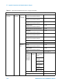
Selection of Protocol Revision
The 3GPP2 Config on the [Configuration: Test Condition] screen
sets the MC-1x and 1xEV-DO protocol revision.
The relationship of MC-1x and 1xEV-DO protocol revision and
the 3GPP2 Config setting is shown in Table 4-2.
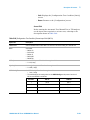
Table 4-2 Relationship of MC-1x/1xEV-DO protocol and 3GPP2 Config
3GPP2
Config
4-18
MC-1x protocol
1xEV-DO protocol
1
Release 0 (Rel. 0)
2
Release A (Rel. A)
3
Release 0 (Rel. 0)
4
Release A (Rel. A)
Release 0 (Rel. 0)
Revision A (Rev. A)
N9360A Multi UE Tester CDMA2000 User Manual
4
Operating Procedure
Correction
Actual Input/Output Level and Correction
1 Actual Output Level and Correction in Automatic Test (Except RF
test), Manual Test, and Signal Generator
Output signal level of the Tester is corrected according to
cable loss, coupling loss, and etc. Some of parameters should
be set properly.
Actual output level (for downlink signal) at the RF IN/OUT
connector in the Automatic Test mode (except RF test), the
Manual Test mode and the Signal Generator mode is
calculated by the following equation.
OutputLevel = BsLevel + LossRFOut
Where,
OutputLevel = Actual output level at the RF IN/OUT
connector.
BsLevel = Setting value at the RF Level on the [Manual Test]
screen, Amplitude on the [Signal Generator] screen,
Amplitude on the [TX Analyzer] screen, Max TX
Power BS Level, Min TX Power BS Level, Measurement
BS Level, FER BS Level (when MC-1x Mode is
selected), PER BS Level1, PER BS Level2 , PER BS Level3
(when 1xEV-DO Mode is selected) on the
[Configuration: Test Sequence] screen.
LossRfOut = Setting value at the RF Out field on the
[Configuration: Test Condition (Loss)] screen.
There is a restriction that the OutputLevel cannot exceed
–18.0 dBm, so at each parameter, the BsLevel and the
LossRfOut must be set to meet this restriction.
2 Actual Input Signal Level and Correction in Automatic Test (Except
RF test), Manual Test, and TX Analyzer
Input signal level of the Tester (for uplink signal) is corrected
according to cable loss, coupling loss, and etc. Some of
parameters should be set properly.
The measurement results of RF test in the Manual Test mode
and the TX Analyzer mode are corrected by the following
equation.
N9360A Multi UE Tester CDMA2000 User Manual
4-19
4
Operating Procedure
InputLevel = MsLevel + LossRFIn
Where,
InputLevel = Corrected measured value of the Tester.
MsLevel = Input signal level of the mobile phone at the RF
IN/OUT connector.
LossRfIn = Setting value at the RF In field on the
[Configuration: Test Condition (Loss)] screen.
3 Actual Output Level and Correction for RF Test in Automatic Test
Output signal level of the Tester is corrected according to
cable loss, coupling loss, and etc. Some of parameters should
be set properly.
Actual output level (for downlink signal) at the RF IN/OUT
connector for RF test in the Automatic Test mode is
calculated by the following equation.
OutputLevel = BsLevel + LossRFOut + AttOut
Where,
OutputLevel = Actual output level at the RF IN/OUT
connector.
BsLevel = [Configuration: The set value when the followings
are specified for the Test Sequence] screen: BS
Level, Measurement BS Level, Max Tx Power BS Level,
Min Tx Power BS Level, FER BS Level (when MC-1x is
selected), PER BS Level1, PER BS Level2 (when
1xEV-DO is selected).
LossRfOut = Setting value at the RF Out field on the
[Configuration: Test Condition (Loss)] screen.
AttOut = Setting value at the ATT Out field on the
[Configuration: Test Sequence] screen.
There are two restrictions. The OutputLevel cannot exceed
–18.0 dBm, so each parameter, the BsLevel, the LossRfOut
and the ATT Out, must be set to meet this restriction. The
other restriction is that the sum of the LossRfOut and the
ATT Out must be set more than or equal to 0.
4-20
N9360A Multi UE Tester CDMA2000 User Manual
4
Operating Procedure
4 Actual Input Signal Level and Correction for RF Test in Automatic
Test
Input signal level of the Tester (for uplink signal) is corrected
according to cable loss, coupling loss, and etc. Some of
parameters should be set properly.
The measurement results of RF test in the Automatic Test
mode are corrected by the following equation.
InputLevel = MsLevel + LossRFIn + AttIn
Where,
InputLevel = Corrected measured value of the Tester.
MsLevel = Input signal level of the mobile phone at the RF
IN/OUT connector.
LossRfIn = Setting value at the RF IN field on the
[Configuration: Test Condition (Loss)] screen.
AttIn = Setting value at the ATT In field on the
[Configuration: Test Sequence] screen.
There is a restriction that the sum of the LossRfIn and ATT
In must be set more than or equal to 0.
N9360A Multi UE Tester CDMA2000 User Manual
4-21
4
Operating Procedure
Entering Loss on the Configuration: Test Condition (Loss) Screen
Determine and enter the loss values caused by the antenna
coupler, RF cable, or shield case used to connect the mobile
phone to the Tester. If the Loss is set to On, these path loss
values are applied to all through the test flow for the band
system being currently tested.
Correction of input/output signal is described in Actual
Input/Output Level and Correction on page 4-19. Also, refer to
Entering Channel Attenuations on the Configuration: Test Sequence
Screen on page 4-23 for the correction of RF test in Automatic
Test.
1 Press the CDMA2000 softkey on the [Top Menu] screen to
activate the cdma2000 system. Refer to Selection of System
on page 4-14 for detail.
2 Press Config > Test Condition > Loss softkeys from the [Initial]
screen to display the [Configuration: Test Condition (Loss)]
screen.
Figure 4-14 [Configuration: Test Condition (Loss)] Screen
4-22
N9360A Multi UE Tester CDMA2000 User Manual
4
Operating Procedure
3 Set the Loss field to On with the CURSOR CONTROL knob.
4 Enter the appropriate loss values, depending on the band, in
the RF In and RF Out fields with the CURSOR CONTROL
knob. These loss values are used all through the test flow.
5 Press the Return softkey to return to the [Initial] screen.
Entering Channel Attenuations on the Configuration: Test
Sequence Screen
This section describes correction for RF test results in
Automatic Test. Each channel (RFCH) path loss value can be set
on the [Configuration: Test Sequence] screen. This is the RF test
correction function in addition to the loss function in the
[Configuration: Test Condition (Loss)] screen.
In addition to entering the loss values on the [Configuration:
Test Condition (Loss)] screen, you can also enter the
attenuation values to be used to correct the RF test results with
these values at each traffic channel in the Automatic Test mode.
Determine and enter the appropriate attenuation values at each
traffic channel with the following procedure, caused by the
antenna coupler, RF cable or shield case to connect the mobile
phone to the Tester.
1 Press the CDMA2000 softkey on the [Top Menu] screen to
activate cdma2000 system. Refer to Selection of System on
page 4-14 for detail.
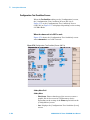
2 Press the Config softkey on the [Initial] screen, and then the
Test Sequence softkey to display the [Configuration: Test
Sequence] screen.
N9360A Multi UE Tester CDMA2000 User Manual
4-23
4
Operating Procedure
Figure 4-15 [Configuration: Test Sequence)] Screen
3 Enter the appropriate attenuation values, depending on the
traffic channel, in the ATT In and ATT Out fields with the
CURSOR CONTROL knob. These values are effective for the
RF tests in the test flow.
4 Press the Return softkey twice to return to the [Initial] screen.
4-24
N9360A Multi UE Tester CDMA2000 User Manual
4
Operating Procedure
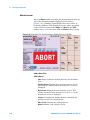
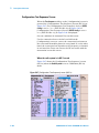
Testing a Dual Band Mobile Phone by Automatic Test (MC-1x Mode)
This section describes the operation method of the Tester and a
dual band (B1:PCS US and B0:Cel US) mobile phone under the
test by Automatic Test MC-1x mode.
This section shows the example of the Tester operation to test
the mobile phone supporting B1:PCS US and B0:Cel US by using
the Automatic Test mode. The handover from the B1:PCS US
and B0:Cel US is performed during the test.
1 Turn on the Tester and select the cdma2000 system on the
[Top Menu] screen. Refer to Selection of System on page 4-14
for selecting a system.
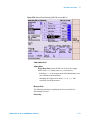
2 The [Initial] screen as Figure 4-16 is displayed after
completion of initialization and self-test routine of the Tester.
Figure 4-16 [Initial] Screen
3 Press Config > Test Condition > Loss softkeys from the [Initial]
screen to display the [Configuration: Test Condition (Loss)]
screen specifying the Loss value.
N9360A Multi UE Tester CDMA2000 User Manual
4-25
4
Operating Procedure
Figure 4-17 [Configuration: Test Condition (Loss)] Screen
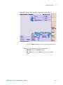
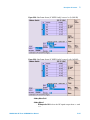
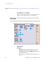
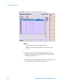
4 Press the Return softkey twice and then the Test Sequence
softkey to display the [Configuration: Test Sequence] screen
for required setting in Automatic Test.
4-26
N9360A Multi UE Tester CDMA2000 User Manual
Operating Procedure
4
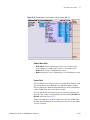
Figure 4-18 [Configuration: Test Sequence1] Screen
Figure 4-19 [Configuration: Test Sequence2] Screen
N9360A Multi UE Tester CDMA2000 User Manual
4-27
4
Operating Procedure
5 Set CDMA2000 MC-1x in Radio System 1 and 2, and set
other fields as shown in Figure 4-18 and Figure 4-19.
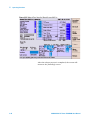
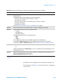
6 Set Run at test item field which you want to execute in the
test flow. Set Run at measurement item cell which you want
to measure in the measurement item table.
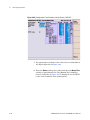
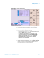
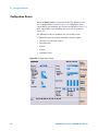
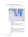
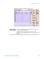
7 Press the Return and then the Test Condition softkey to display
the [Configuration: Test Condition] screen as Figure 4-20 to
set the test condition.
Figure 4-20 [Configuration: Test Condition] Screen
8 Set the fields of the test parameters as shown in the left and
upper right side of Figure 4-20 with the CURSOR CONTROL
knob.
9 Repeat step 8 to set the test condition for Cel US after
replacing B1:PCS US to B0:Cel US at the Band field.
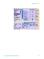
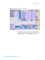
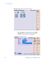
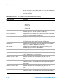
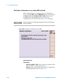
10 Press the Limit softkey to display the [Configuration: Test
Condition (Limit)] Screen as Figure 4-21.
4-28
N9360A Multi UE Tester CDMA2000 User Manual
4
Operating Procedure
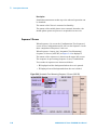
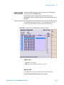
Figure 4-21 [Configuration: Test Condition (Limit)] Screen
11 Set appropriate test limits in the cells of the test item table in
the upper right side of Figure 4-21.
12 Repeat step 11 to set the test condition for Cel US after
replacing B1:PCS US to B0:Cel US at the Band field.
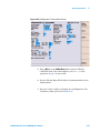
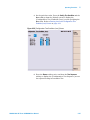
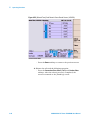
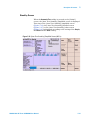
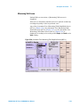
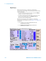
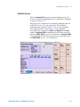
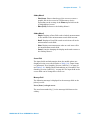
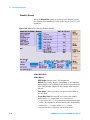
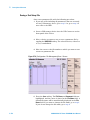
13 Press the Return softkey three times and then the Automatic
Test softkey to start Automatic Test. The [Auto Test:
Stand-by] screen as Figure 4-22 is displayed. Press the
Screen>> softkey to select the display mode. Select Simple,
Detail or Value softkey. The following Figure 4-22 is a value
screen which will show a measured value for each
measurement item.
N9360A Multi UE Tester CDMA2000 User Manual
4-29
4
Operating Procedure
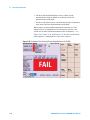
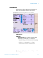
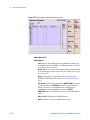
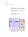
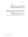
Figure 4-22 [Automatic Test: Stand-by] Value Screen (MC-1x)
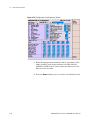
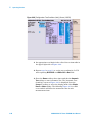
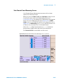
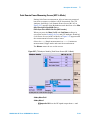
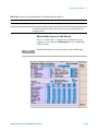
14 Press the Start softkey to start a test. A screen status changes
from Stand-by to Measuring.
15 Turn the mobile phone on. Wait for the mobile phone to camp
on, and P is shown at the Location Update step.
16 At the MS Call step, make a call from the mobile phone. Dial
an arbitrary number and press the Off Hook button on the
mobile phone.
17 At the Talk step, check the quality of loop back voice and
press the Pass or the Fail softkey according to its result.
18 At the MS Release step, press the Off Hook button on the
mobile phone to terminate the call from the mobile phone.
19 At the BS Call (Talk) step, press the Off Hook button on the
mobile phone to respond to the call from the Tester.
4-30
N9360A Multi UE Tester CDMA2000 User Manual
4
Operating Procedure
20 At the Talk step, check the quality of loop back voice and
press the Pass or the Fail softkey according to its result.
21 At the BS Release step, the Tester automatically finishes the
call.
22 At the BS Call (RF Test) step, the mobile phone automatically
responds to the call from the Tester.
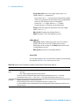
23 As each step is running in the test flow, the corresponding
test item field in the table is highlighted. While the RF Test
step is highlighted, each of the measurement items is
measured. So, you can see how it is being done.
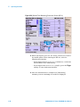
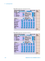
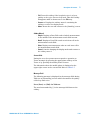
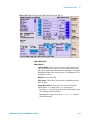
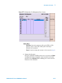
24 At the System Handoff step, handover PCS US to Cel US. A
screen status changes to Sequence2.
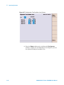
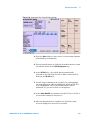
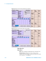
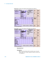
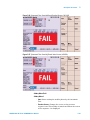
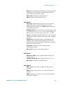
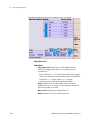
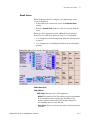
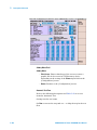
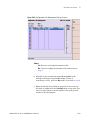
25 After the measurement is completed, a [Stand-by] Value
screen is displayed to show the test results.
Figure 4-23 [Automatic Test: Stand-by] Value Screen (MC-1x)
N9360A Multi UE Tester CDMA2000 User Manual
4-31
4
Operating Procedure
26 If a printer is available, print the test results. Press the More
(1 of 2) softkey, and then the Print Screen softkey to print a
screen hardcopy.
27 Press the More (2 of 2) softkey to return to the previous
softkey menu.
28 If you want to repeat the same test again, press the Start
softkey.
4-32
N9360A Multi UE Tester CDMA2000 User Manual
4
Operating Procedure
Testing a Dual Band Mobile Phone by Manual Test (MC-1x Mode)
This section describes the operation method of the Tester and a
dual band (B1: PCS US and B0: Cel US) mobile phone under the
test by the Manual Test MC-1x mode.
This section shows the example of the Tester operation to test
the mobile phone supporting B1:PCS US and B0:Cel US by using
the Manual Test mode.
1 Turn on the Tester and select the cdma2000 system on the
[Top Menu] screen. Refer to Selection of System on page 4-14
for selecting a system.
2 The [Initial] screen as Figure 4-24 is displayed after
completion of initialization and self-test routine of the Tester.
When CDMA Mode is not set to MC-1x, change to MC-1x
mode by pressing the CDMA Mode >> and MC-1x softkeys.
Figure 4-24 [Initial] Screen
3 Set the path loss value. Press the Config > Test Condition > Loss
softkeys from the [Initial] screen to display the
N9360A Multi UE Tester CDMA2000 User Manual
4-33
4
Operating Procedure
[Configuration: Test Condition (Loss)] screen specifying the
Loss value. Refer to Entering Loss on the Configuration: Test
Condition (Loss) Screen on page 4-22.
Figure 4-25 [Configuration: Test Condition (Loss)] Screen
4 Press the Return softkey to display the [Configuration: Test
Condition] screen for required setting in Manual Test MC-1x
mode.
4-34
N9360A Multi UE Tester CDMA2000 User Manual
4
Operating Procedure
Figure 4-26 [Configuration: Test Condition] Screen
5 Select MC-1x at the CDMA Mode field with the CURSOR
CONTROL knob. This value might be set to MC-1x, if the
operation of step 2 is proceeded.
6 Set the SID and Rgstr SID fields for requiring number of the
mobile phone.
7 Press the Limit softkey to display the [Configuration: Test
Condition (Limit)] Screen as Figure 4-27.
N9360A Multi UE Tester CDMA2000 User Manual
4-35
4
Operating Procedure
Figure 4-27 [Configuration: Test Condition (Limit)] Screen
8 Set the appropriate test limits in the cells of the test item
table in the right side of the Figure 4-27.
9 Press the Return softkey three times and then the Manual Test
softkey to start Manual Test. The [Manual Test: Stand-by]
Screen (MC-1x) as Figure 4-28 is displayed. Set the RFCH to
the control channel of the mobile phone.
4-36
N9360A Multi UE Tester CDMA2000 User Manual
4
Operating Procedure
Figure 4-28 [Manual Test: Stand-by] Screen (MC-1x)
10 Press the Location Update softkey, and turn the mobile phone
on. Wait for it to camp on, and P is shown at the Location
Update step.
11 Set the Service Option field to 2, 9, 32 or 55 to start RF test. Set
the Service Option field to 1, 3 or 17 to start voice test.
12 Start MS Call or BS Call with the following operation.
• Dial an arbitrary number and press the Off Hook button on
the mobile phone.
• Press the BS Call softkey to start BS Call. Press Off Hook
button on the mobile phone to respond to the call from the
Tester.
13 After MS call or BS call, the screen as Figure 4-29 is
displayed. P is shown at the MS Call or BS Call step as the test
result of MS Call or BS Call, and Connection is highlighted.
N9360A Multi UE Tester CDMA2000 User Manual
4-37
4
Operating Procedure
Figure 4-29 [Manual Test: Measuring] Connection Screen (MC-1x)
14 When starting the voice test, the Tester returns voice back to
the mobile phone. When starting the RF test, refer the
following descriptions.
• If the trigger mode is set to Cont (continuous), continuous
measurement starts immediately.
• If the trigger mode is set to Sing (single), press the Trigger
softkey to start single measurement.
15 After the measurement is completed, a [Measuring]
summary screen containing test results is displayed.
4-38
N9360A Multi UE Tester CDMA2000 User Manual
4
Operating Procedure
Figure 4-30 [Manual Test: Measuring] Result Screen (MC-1x)
16 Press the Meas Max & Min TX Power softkey to measure
maximum and minimum TX Power. To measure maximum
and minimum TX Power, set the Service Option field to either
of 2, 9, 32 and 55.
N9360A Multi UE Tester CDMA2000 User Manual
4-39
4
Operating Procedure
Figure 4-31 [Manual Test: Measuring] Max & Min TX Power Summary Screen (MC-1x)
17 If you want to measure the Code Domain Power, press the
More (1 of 3) and Code Power softkeys to display the Code
Domain Power measurement screen. To measure the Code
Domain Power, set the Service Option field to either of 2, 9, 32
and 55.
• If the trigger mode is set to Cont (continuous), continuous
measurement starts immediately.
• If the trigger mode is set to Sing (single), press the Trigger
softkey to start single measurement.
4-40
N9360A Multi UE Tester CDMA2000 User Manual
4
Operating Procedure
Figure 4-32 [Manual Test] Code Domain Power Result Screen (MC-1x)
• Press the Return softkey to return to the previous screen.
18 Release the call with the following operation.
• BS release: Press the Release softkey.
• MS release: Press the On Hook button on the mobile
phone.
N9360A Multi UE Tester CDMA2000 User Manual
4-41
4
Operating Procedure
Figure 4-33 [Manual Test: Stand-by] Result Screen (MC-1x)
After the release process is completed, the screen will
return to the [Stand-by] screen.
4-42
N9360A Multi UE Tester CDMA2000 User Manual
4
Operating Procedure
Handoff
Softer Handoff
1 Follow the process of step 1 to step 13 of Testing a Dual Band
Mobile Phone by Manual Test (MC-1x Mode) and set the
mobile phone to call connection status.
2 Press the More (1 of 2) and Softer Handoff softkeys to start
Softer handoff. The Softer Handoff step is highlighted. When
the handoff is completed, P is shown at the Softer Handoff
step.
3 Release the call with the following operation.
• BS release: Press the Release softkey.
• MS release: Press the On Hook button on the mobile
phone.
After the release process is completed, the screen is returned
to the [Stand-by] screen.
Hard Handoff
1 Follow the process of step 1 to step 13 of Testing a Dual Band
Mobile Phone by Manual Test (MC-1x Mode) and set the
mobile phone to call connection status.
2 Change the channel with the following operation.
• Move the cursor to the RFCH input field and press the
CURSOR CONTROL knob.
• Rotate the CURSOR CONTROL knob to select the channel
for handoff and press the CURSOR CONTROL knob again.
When the channel in the same band is selected, the Hard
Handoff step is highlighted. When the channel in the
different band is selected, Band Handoff step is highlighted
and the channel is changed to the selected one.
• When the handoff is completed, P is shown at the Hard
Handoff or Band Handoff step.
3 Release the call with the following operation.
• BS release: Press the Release softkey.
• MS release: Press the On Hook button on the mobile
phone.
After the release process is completed, the screen is returned
to the [Stand-by] screen.
N9360A Multi UE Tester CDMA2000 User Manual
4-43
4
Operating Procedure
Emergency Call
NOTE
To test the emergency call function, place the mobile phone and the
Tester where the radio signal (electromagnetic wave) from base station of
a cell phone operator does not propagate, such as in a shield room, an
anechoic chamber, and etc.
1 Follow the process of step 1 to step 11 of Testing a Dual Band
Mobile Phone by Manual Test (MC-1x Mode) and set the
mobile phone to Stand-by status.
2 Set the Service Option to 1, 3 or 17.
3 Dial an emergency call number and press an Off Hook button
on the mobile phone to start MS Call.
4 After MS call starts, the screen as Figure 4-34 will be
displayed. Emergency Call with dialed number is displayed
at the Dialed No. field on the screen. P is shown at the MS Call
step, and Connection is highlighted. (The Emergency Call
message is displayed only when the mobile phone supports
the protocol revision 7 and the 3GPP2 Config is set to 2 or 4 for
MC-1x Rel. .A.)
4-44
N9360A Multi UE Tester CDMA2000 User Manual
Operating Procedure
4
Figure 4-34 [Manual Test: Measuring] MS Call Emergency Call Screen (MC-1x)
N9360A Multi UE Tester CDMA2000 User Manual
4-45
4
Operating Procedure
Tests using 1xEV-DO Mode(Option C02)
Testing a Dual Band Mobile Phone by Automatic Test
(1xEV-DO Mode)
This section describes the operation method of the Tester and a
dual band (B1:PCS US and B0:Cel US) mobile phone under the
test by Automatic Test 1xEV-DO mode. The handoff from the
B1:PCS US and B0:Cel US is performed during the test. Set the
mobile phone to 1xEV-DO Only mode before measurement.
1 Turn on the Tester and select the cdma2000 system on the
[Top Menu] screen. Refer to Selection of System on
page 4-14.
2 The [Initial] screen as Figure 4-35 is displayed after
completion of initialization and self-test routine of the Tester.
Figure 4-35 [Initial] Screen
4-46
N9360A Multi UE Tester CDMA2000 User Manual
Operating Procedure
4
3 Set the path loss value. Press the Config, Test Condition and the
Loss softkeys from the [Initial] screen to display the
[Configuration: Test Condition (Loss)] screen specifying the
Loss value. Refer to Entering Loss on the Configuration: Test
Condition (Loss) Screen on page 4-22.
Figure 4-36 [Configuration: Test Condition (Loss)] Screen
4 Press the Return softkey twice and then the Test Sequence
softkey to display the [Configuration: Test Sequence] screen
for required setting in Automatic Test.
N9360A Multi UE Tester CDMA2000 User Manual
4-47
4
Operating Procedure
Figure 4-37 [Configuration: Test Sequence1] Screen
Figure 4-38 [Configuration: Test Sequence 2] Screen
4-48
N9360A Multi UE Tester CDMA2000 User Manual
4
Operating Procedure
5 Set CDMA2000 1xEV-DO in Radio System 1 and 2, respectively,
and set other fields as shown in Figure 4-37 and Figure 4-38.
6 Set Run at test item field which you want to execute in the
test flow.
7 Set Run at measurement item cell which you want to measure
in the measurement item table.
8 Press the Return softkey and then the Test Condition softkey to
display the [Configuration: Test Condition] Screen as
Figure 4-39 to set the test condition.
Figure 4-39 [Configuration: Test Condition] Screen (1xEV-DO)
9 Set the fields of the test parameters as shown in the left and
upper right side of Figure 4-39 with the CURSOR CONTROL
knob.
10 Press the Limit softkey to display the [Configuration: Test
Condition (Limit)] Screen (1xEV-DO) as Figure 4-40.
N9360A Multi UE Tester CDMA2000 User Manual
4-49
4
Operating Procedure
Figure 4-40 [Configuration: Test Condition (Limit)] Screen (1xEV-DO)
11 Set appropriate test limits in the cells of the test item table in
the upper right side of Figure 4-40.
12 Repeat step 8 to step 11 to set the test condition for Cel US
after replacing B1:PCS US with B0:Cel US in Band field.
13 Press the Return softkey three times and then the Automatic
Test softkey to start Automatic Test. The [Automatic Test:
Stand-by] screen as Figure 4-41 is displayed. Press the
Screen>> softkey to select the display mode. Select Simple,
Detail or Value softkey. The following Figure 4-41 is a value
screen which will show the measured value for each
measurement item.
4-50
N9360A Multi UE Tester CDMA2000 User Manual
4
Operating Procedure
Figure 4-41 [Automatic Test: Stand-by] Value Screen
14 Press the Start softkey to start a test. A screen status changes
from Stand-by to Measuring.
15 Turn the mobile phone on. Wait for the mobile phone to camp
on, and P is shown at the UATI Assignment step.
16 At the BS Call step, , the mobile phone automatically
responds to the call from the Tester. When connected, P is
shown at the BS Call step.
17 As each step is running in the test flow, its corresponding
test item field in the table is highlighted. While the RF Test
step is highlighted, each of the measurement items is
measured. So, you can see how it is being done.
18 At the Softer Handoff step, handover from PCS US to Cel US. A
screen status changes to Sequence 2.
19 After the measurement is completed, a [Stand-by] value
screen is displayed to show the test results.
N9360A Multi UE Tester CDMA2000 User Manual
4-51
4
Operating Procedure
Figure 4-42 [Automatic Test: Stand-by] Result Screen
20 If a printer is available, print the test results.
Press the More (1 of 2) softkey, and then the Print Screen
softkey to print a screen hardcopy.
21 Press the More (2 of 2) softkey to return to the previous
softkey menu.
22 If you want to repeat the same test again, press the Start
softkey.
4-52
N9360A Multi UE Tester CDMA2000 User Manual
4
Operating Procedure
Testing a Dual Band Mobile Phone by Manual Test (1xEV-DO Mode)
This section describes the operation method of the Tester and a
dual band (PCS US and Cel US) mobile phone under the test by
the Manual Test 1xEV-DO mode. Set the mobile phone to
1xEV-DO Only mode before measurement.
1 Turn on the Tester and select the cdma2000 system on the
[Top Menu] screen. Refer to Selection of System on page 4-14
for selecting a system.
2 The [Initial] screen as Figure 4-43 is displayed after
completion of initialization and self-test routine of the Tester.
When CDMA Mode is not set to 1xEV-DO, switch to 1xEV-DO
mode by pressing CDMA Mode >> and then 1xEV-DO softkeys.
Figure 4-43 [Initial] Screen
3 Set the path loss value. Press the Config, Test Condition and the
Loss softkeys from the [Initial] screen to display the
N9360A Multi UE Tester CDMA2000 User Manual
4-53
4
Operating Procedure
[Configuration: Test Condition (Loss)] screen specifying the
Loss value. Refer to Entering Loss on the Configuration: Test
Condition (Loss) Screen on page 4-22.
Figure 4-44 [Configuration: Test Condition (Loss)] Screen
4 Press the Return softkey to display the [Configuration: Test
Condition] screen for required setting in Manual Test
1xEV-DO mode.
4-54
N9360A Multi UE Tester CDMA2000 User Manual
4
Operating Procedure
Figure 4-45 [Configuration: Test Condition] Screen
5 Select 1xEV-DO at the CDMA Mode field by using the CURSOR
CONTROL knob. This value might be set to 1xEV-DO, if the
operation of step 2 is preceded.
6 Press the Limit softkey to display the [Configuration: Test
Condition (Limit)] Screen (1xEV-DO) as Figure 2.46.
N9360A Multi UE Tester CDMA2000 User Manual
4-55
4
Operating Procedure
Figure 4-46 [Configuration: Test Condition (Limit)] Screen (1xEV-DO)
7 Set appropriate test limits in the cells of the test item table in
the upper right side of Figure 4-46.
8 Press the Return softkey three times and then the Manual Test
softkey to start Manual Test. The [Manual Test: Stand-by]
Screen (1xEV-DO) as Figure 4-47 is displayed. Set the RFCH
to the control channel of the mobile phone.
4-56
N9360A Multi UE Tester CDMA2000 User Manual
4
Operating Procedure
Figure 4-47 [Manual Test: Stand-by] Screen (1xEV-DO)
9 Press the UATI Assign softkey, and turn the mobile phone
on. Wait for the mobile phone to camp on. P is shown at the
UATI Assignment step, and Session Opened is highlighted.
N9360A Multi UE Tester CDMA2000 User Manual
4-57
4
Operating Procedure
Figure 4-48 [Manual Test: Measuring] UATI Assignment Screen (1xEV-DO)
10 Press the BS Call softkey. The mobile phone replies
automatically. After BS call starts, the screen as shown in
Figure 4-49 is displayed. P is shown at the BS Call step as the
test result of BS Call, and Connection is highlighted.
4-58
N9360A Multi UE Tester CDMA2000 User Manual
4
Operating Procedure
Figure 4-49 [Manual Test: Measuring] BS Screen (1xEV-DO)
11 When starting the RF Test, refer the following descriptions.
• If the trigger mode is set to Cont (continuous), continuous
measurement starts immediately.
• If the trigger mode is set to Sing (single), press Trigger
softkey to start single measurement.
12 After the measurement is completed, a [Measuring]
summary screen containing test results is displayed.
N9360A Multi UE Tester CDMA2000 User Manual
4-59
4
Operating Procedure
Figure 4-50 [Manual Test: Measuring] Result Screen (1xEV-DO)
13 Press the Meas Max & Min TX Power softkey to measure Max &
Min TX Power.
4-60
N9360A Multi UE Tester CDMA2000 User Manual
4
Operating Procedure
Figure 4-51 [Manual Test: Measuring] Max & Min TX Power Screen (1xEV-DO)
14 When measuring Code Domain Power, press the More (1 of 3)
and Code Power softkeys to display the Code Domain Power
measurement screen. Perform Code Domain Power
measurement in accordance with the trigger mode setting
described below.
• If the trigger mode is set to Cont (continuous), continuous
measurement starts immediately.
• If the trigger mode is set to Sing (single), press Trigger
softkey to start single measurement.
N9360A Multi UE Tester CDMA2000 User Manual
4-61
4
Operating Procedure
Figure 4-52 [Manual Test] Code Domain Power Result Screen (1xEV-DO)
• Press the Return softkey to return to the previous screen.
15 Release the call with the following operation.
• Press the Connection Close, More (1 of 3) and Session Close
softkeys. After the release process is completed, the
screen is returned to the [Stand-by] screen.
4-62
N9360A Multi UE Tester CDMA2000 User Manual
Operating Procedure
4
Figure 4-53 [Manual Test: Stand-by] Result Screen (1xEV-DO)
N9360A Multi UE Tester CDMA2000 User Manual
4-63
4
Operating Procedure
Handoff
Softer Handoff
1 Follow the process of step 1 to step 10 of Testing a Dual Band
Mobile Phone by Manual Test (1xEV-DO Mode) and set the mobile
phone to call connection status.
2 Press More (1 of 3) and Softer Handoff softkeys to start Softer
handoff. The Softer Handoff step is highlighted. When the
handoff is completed, P is shown at the Softer Handoff step.
3 Release the call with the following operation.
• Press the Connection Close, More (1 of 3) and Session Close
softkeys.
Hard Handoff
1 Follow the process of step 1 to step 10 of Testing a Dual Band
Mobile Phone by Manual Test (1xEV-DO Mode) and set the mobile
phone to call connection status.
2 Change the channel with the following operation.
• Move the cursor to RFCH input field and press the
CURSOR CONTROL knob.
• Rotate the CURSOR CONTROL knob to select the channel
for handoff and press the CURSOR CONTROL knob again.
When the channel in the same band is selected, the
Channel Change step is highlighted. When the channel in
the different band is selected, Band Change step is
highlighted and the channel is changed to the selected
one.
• When handoff is completed, P is shown at the Channel
Change or Band Change step.
3 Release the call with the following operation.
• BS release: Press the Connection Close, More (1 of 3) and
Session Close softkeys.
4-64
N9360A Multi UE Tester CDMA2000 User Manual
4
Operating Procedure
Testing a Mobile Phone by TX Analyzer
This section describes the operation method of the Tester for a
test by the TX Analyzer.
1 Turn on the Tester and select the cdma2000 system on the
[Top Menu] screen. Refer to Selection of System on page 4-14
for selecting a system.
2 The [Initial] screen as Figure 4-54 is displayed after
completion of initialization and self-test routine of the Tester.
Figure 4-54 [Initial] Screen
3 Set the path loss values. Press the Config, Test Condition and
then the Loss softkeys from the [Initial] screen to display the
[Configuration: Test Condition (Loss)] screen specifying the
Loss value. Refer to Entering Loss on the Configuration: Test
Condition (Loss) Screen on page 4-22.
N9360A Multi UE Tester CDMA2000 User Manual
4-65
4
Operating Procedure
Figure 4-55 [Configuration: Test Condition (Loss)] Screen
4 Press the Return softkey to display the [Configuration: Test
Condition] screen to set the test condition.
4-66
N9360A Multi UE Tester CDMA2000 User Manual
Operating Procedure
4
Figure 4-56 [Configuration: Test Condition] Screen
5 Set the input fields of the test parameter as shown in
Figure 4-56.
6 Press the Limit softkey to display the [Configuration: Test
Condition (Limit)] screen as Figure 4-57.
N9360A Multi UE Tester CDMA2000 User Manual
4-67
4
Operating Procedure
Figure 4-57 [Configuration: Test Condition (Limit)] Screen
7 Enter appropriate test limits in the cells of the test item table
on the [Configuration: Test Condition] screen.
8 Press the Return softkey three times and the TX Analyzer
softkey. The [TX Analyzer: Stand-by] screen as Figure 4-58 is
displayed.
4-68
N9360A Multi UE Tester CDMA2000 User Manual
4
Operating Procedure
Figure 4-58 [TX Analyzer: Stand-by] Screen
9 Set the mobile phone to transmit the bursted RF signal.
10 Start a test with the following operation.
• When the trigger mode is Sing, single measurement starts
after the Trigger softkey is pressed.
• To change the trigger mode to Cont in order to start
continuous measurement, press the Trigger Sing/Cont
softkey. When the trigger mode is Cont, continuous
measurement starts as soon as the [TX Analyzer:
Stand-by] screen is displayed.
11 During continuous measurement, press the Trigger Sing/Cont
softkey to terminate continuous measurement. A screen
showing measurement results is displayed.
N9360A Multi UE Tester CDMA2000 User Manual
4-69
4
Operating Procedure
Figure 4-59 [TX Analyzer: Stand-by] Result Screen
4-70
N9360A Multi UE Tester CDMA2000 User Manual
4
Operating Procedure
Testing a Mobile Phone by Signal Generator
This section describes the operation method of the Tester for a
test by the Signal Generator.
1 Turn on the Tester and select the cdma2000 system on the
[Top Menu] screen. Refer to Selection of System on page 4-14
for selecting a system.
2 The [Initial] screen as Figure 4-60 is displayed after
completion of initialization and self-test routine of the Tester.
Figure 4-60 [Initial] Screen
3 Set the path loss values. Press the Config, Test Condition and
then the Loss softkeys from the [Initial] screen to display the
[Configuration: Test Condition (Loss)] screen specifying the
Loss value. Refer to Entering Loss on the Configuration: Test
Condition (Loss) Screen on page 4-22.
N9360A Multi UE Tester CDMA2000 User Manual
4-71
4
Operating Procedure
Figure 4-61 [Configuration: Test Condition (Loss)] Screen
4 Press the Return three times and then press the Signal
Generator softkey on the [Initial] screen. The [Signal
Generator] screen as Figure 4-62 is displayed.
Figure 4-62 [Signal Generator] Screen
4-72
N9360A Multi UE Tester CDMA2000 User Manual
Operating Procedure
4
5 Set the input fields.
6 Press the RF Output On/Off softkey to change On/Off state from
Off to On for transmitting RF signal to the mobile phone.
7 Press the RF Output On/Off softkey again to change On/Off state
from On to Off for termination of the test.
N9360A Multi UE Tester CDMA2000 User Manual
4-73
4
Operating Procedure
Ending a Test
CAUTION
In the Tester, the HDD is used for storage.
Do not turn off the Line switch on the rear panel of the Tester while
the LINE LED on the front panel of the Tester is lit in green.
Otherwise, Tester failure may occur.
Disconnecting the Mobile Phone
Disconnect the mobile phone from the connection cable or the
antenna coupler.
Turning off the Tester
Turn off the Tester with the following procedure.
1 Press the LINE switch on the front panel of the Tester for
more than one second.
2 The display blacks out, and the LINE LED on the front panel
is lit in orange.
3 The power is turned off except the reference oscillator in the
Tester.
4 Turn off the Line switch on the rear panel of the Tester to
turn off the reference oscillator.
5 All power including the reference oscillator is turned off and
the LINE LED goes off.
4-74
N9360A Multi UE Tester CDMA2000 User Manual
Agilent N9360A Multi UE Tester
CDMA2000 User Manual
5
Description of Screens
Screen Structure 5-2
Top Menu Screen 5-3
Configuration Screen 5-6
Firmware Update Screen 5-12
Update Flash Screen 5-16
Network Setting 5-19
Initial Screen 5-23
Return to Menu Screen 5-26
PRESET Mode Selection Screen 5-27
Automatic Test (MC-1x Mode) 5-29
Measuring Screen 5-36
Manual Test (MC-1x Mode) 5-51
Automatic Test (1xEV-DO Mode) 5-76
Measuring Screen 5-83
Manual Test (1xEV-DO Mode) 5-94
TX Analyzer 5-114
Signal Generator 5-131
Modulation Waveform 5-135
Configuration 5-137
This chapter describes how to use the screens as well as the
behavior of each screen and the softkeys available on each
screen.
Agilent Technologies
5-1
5
Description of Screens
Screen Structure
The following Figure 5-1 shows the screen structure that
consists of screens for each mode. Each box represents a screen
in a different mode or test conditions.
Figure 5-1
Screen Structure
Top
Menu
Conf
igurati
on
Select
" W-CDMA" or
" GSM"
Refer
the W-CDMA User’ s Guide
or
the GSM User’ s Guide
Firmw
Upda are
te
Select
" CDMA2000"
In
S oftk itial
ey M
enu
nlock
est
lkey U
Pa ne
atic T
utom
A
Initia
S cree l
n
S tand
S ta
V -by
S tand Dentd-by alue
ail
-by
S imple
Meas
urin
Meas
urin Value g
Meas
uringDetail g
S imple
Manu
Mea
Measu Vasluuring
e
rin
Meas
u Detail g
S imp ring
le
al T
Manu
est
S tan
d-by
Code
Po
Meas wer
.
S tand
-by
er
nalyz
TX A
Measu
ring
naly
TX A
S tand
-by
S ta
d-by Value
S tand Denta
il
S imp by
le
Meas
uring
st
al Te
Code
Po
Meas wer
.
ock
lke y L
Pan e
S tand
-by
Meas
uring
Code
P owe
Meas r
.
zer
S tand
-by
al
Sign
Meas
uring
Code
P owe
Meas r
.
ra tor
Gene
S na
Genig
eratlo
r
tor
nera
al Ge
Sign
S ig
Gene nal
rator
Confi
gurati
on
5-2
tio n
igura
Conf
Conf
igurat
ion
FW R
evisio
Netw
n
ork
M File S etting
Test
Condanagemen
ition
t
Test
S equ
ence
F
Netw W Revisio
n
S ettinork
ManaFile
g
Test
Cond gement
Test
ition
S equ
ence
L oss
N9360A Multi UE Tester CDMA2000 User Manual
Description of Screens
5
Top Menu Screen
After power on, the [Top Menu] screen as Figure 5- 2 is
displayed.
This screen is used to select a system or to display the
[Configuration] screen.
Options for the Tester system are GSM, W- CDMA, and/or
cdma2000.
Figure 5-2
Top Menu Structure
Menu
GSM
NOTE
WCDMA
cdma2000
Configuration
Firmware Update
This N9360A Multi UE Tester CDMA2000 USer Manual provides
information for the cdma2000 system only. For the GSM system, refer to
the N9360A Multi UE Tester GSM User Manual; for the W-CDMA system,
refer to the N9360A Multi UE Tester W-CDMA User Manual.
N9360A Multi UE Tester CDMA2000 User Manual
5-3
5
Description of Screens
Figure 5-3 [Top Menu] Screen
Softkey Menu Field
Softkey Menu 1
• GSM: Selects the GSM system. After the system is selected,
the Tester is automatically rebooted, and then displays
the [Initial] screen for GSM system. This softkey is
activated when the GSM system is installed in the Tester.
• WCDMA: Selects the W-CDMA system. After the system is
selected, the Tester is automatically rebooted, and then
displays the [Initial] screen for W-CDMA system. This
softkey is activated when the W-CDMA system is installed
in the Tester.
• CDMA2000: Selects the cdma2000 system. When the system
is selected, the Tester automatically restarts and the
[Initial] screen for the cdma2000 system appears. This
softkey is available only when the cdma2000 system is
installed on the Tester.
• More (1 of 2): Displays the Softkey Menu 2.
• Config: Displays the [Configuration] screen.
5-4
N9360A Multi UE Tester CDMA2000 User Manual
Description of Screens
5
Softkey Menu 2
• Print Screen: Prints a hardcopy of the screen or saves an
image file of the screen into a USB memory device
depending on the setting of the Printer field on the
[Configuration] screen.
• Reboot: Aborts the current system and returns the [Top
Menu] screen after reboots the Tester.
• More (2 of 2): Displays the Softkey Menu 1.
NOTE
When the Autoboot function is set to FUNC GSM, FUNC WCDMA, or FUNC
CDMA2000, the Tester will automatically displays the [Initial] screen for
the GSM, W-CDMA or cdma2000 system mode if no softkey is pressed
within the specified time (10 to 60 seconds). When the Tester is shipped,
the AutoBoot function is set to None.
Screen Field
This area displays the name, revision number, serial number,
and other information of the firmware that is currently
installed.
Message Field
The following message is displayed in the message field:
Select a Radio System or Configuration.
N9360A Multi UE Tester CDMA2000 User Manual
5-5
5
Description of Screens
Configuration Screen
When the Config softkey is pressed on the [Top Menu] screen,
the [Configuration] screen as Figure 5-4 is displayed. If the
option E02 is not installed, the screen is as shown in Figure 5-5;
if the option E01 is not installed, the screen is as shown in
Figure 5-6.
The following various conditions are set on this screen.
• Signal decrease of internal/external reference signal
• Interface for external control
• Date and time
• Printer
• Beeper
• Automatic Boot
Figure 5-4 [Configuration] Screen
5-6
N9360A Multi UE Tester CDMA2000 User Manual
5
Description of Screens
Softkey Menu Field
Softkey Menu
• Print Screen: Prints a hardcopy of the screen or saves it in a
USB memory device depending on the setting of the Printer
input field on the [Configuration] screen.
• FW Update: Displays the [Firmware Update] screen.
• Network Setting: Displays the [Network Setting] screen.
• Option Install: Used to install option functions to display in
E01 or E02.
• Option Backup: Backs up the installed option functions.
• Return: Returns to the [Top Menu] screen.
When the Option E02 is not installed in the Tester, the GP-IB
field is displayed in gray (inactivated) as shown in Figure 5-5.
Figure 5-5
Part of [Configuration] screen (without Option E02)
When the Option E01 is not installed in the Tester, the Serial Port
GP-IB field is displayed in gray (inactivated) as Figure 5-6.
Figure 5-6
N9360A Multi UE Tester CDMA2000 User Manual
Part of [Configuration] screen (without Option E01)
5-7
5
Description of Screens
Screen Field
Set the input items required to use the Tester, referring to the
description shown in Table 5-1.
Table 5-1 Input Items on the [Configuration] Screen
Input Field
Reference
Description
Selects the reference signal from Internal and External.
• Internal: Use the internal 10 MHz reference signal.
• External: Use the external 10 MHz reference signal. The 10 MHz reference signal must be supplied
to the 10MHz Reference IN connector on the rear panel.
Serial Port
Sets the serial (RS-232C) port communication condition to use external control. This function is
unavailable without E01/E02 option.
• Baud Rate: Sets communication speed to 9600, 19200, 38400, 57600 or 115200 bits per
second.
• Data Length: Sets data length to 7 or 8 bits.
• Stop Bits: Sets stop bit length to 1, 1.5 or 2 bits.
• Parity: Sets parity check mode to None, Odd or Even.
• Xcontrol: Sets flow control to None or Xon/Xoff.
Ethernet *
Set various settings for external control via an Ethernet port.
• IP Addr: Specifies the IP address.
• Mask: Specifies the net mask.
• Determine whether the Tester should be controlled via the router or gateway installed outside.
• None: Controls the Tester without using the router and gateway.
• ACT: Controls the Tester using the router or gateway.
• Addr: Determine whether the Tester should be controlled via the router or gateway installed
outside. This item is available when Gateway is set to ACT.
Reboot the Tester after changing Ethernet setting.
GP-IB *
Sets the communication condition of the GP-IB port to use remote control. The option E02 is required
to use this function.
• Addr: Sets the address. The allowable range is from 1 to 15.
• EOI: Sets EOI control. Select On or Off.
• On: Enables EOI control. (Terminator setting is ignored).
• Off: Disables EOI control. (Terminator setting is valid).
Reboot the Tester after changing GP-IB setting.
Terminator
Sets a terminator of output text data to CR, LF or CR+LF. This setting is used for external control
with Serial, Ethernet and GP-IB.
(The Terminator of input text data is always LF)
Printer
Set the destination to which the print data is sent when it is printed (when the Print Screen softkey is
pressed) to USB Memory or EPSON PM-G800.
• USB Memory: Saves a graphic file of screen in a USB memory device. The image format is PNG
(Portable Network Graphics).
• EPSON PM-G800: Prints a hardcopy of the screen in the specified printer.
5-8
N9360A Multi UE Tester CDMA2000 User Manual
5
Description of Screens
Table 5-1 Input Items on the [Configuration] Screen
Input Field
Description
Beeper
Sets the beep sound.
Selects On or Off.
• On: Beeps for each step of operation.
• Off: Beeps only for noticing some errors and warnings.
AutoBoot
Selects the system for automatic boot when a certain time (time-out period) has passed since the [Top
Menu] screen was displayed.
• Application: Sets the system from the followings
• None: Not automatically boots
• FUNC GSM: Boots the GSM option
• FUNC WCDMA: Boots the W-CDMA option
• FUNC CDMA2000:Boots the cdma2000 option
• Timer: Sets the timeout timer from 10 to 60 seconds, or -. The timer is stopped if any softkey is
pressed.
• —: Invalid when Application is set to None.
• 10 to 60: Specifies timeout timer.
Date/ Time *
Sets the current date and time in the following formats:
• YYYY: Sets the year. The allowable range is from 1990 to 2037.
• MM: Sets the month. The allowable range is from 01 to 12.
• DD: Sets the day. The allowable range is from 01 to 31.
• HH: Sets the hour. The allowable range is from 00 to 23.
• MM: Sets the minute. The allowable range is from 00 to 59.
Option Install
Installs Option. Set 16-digit option key and press
Option Install softkey without USB memory inserted.
* The changing magnification softkey is available. Refer to Storing Numeric Values on page 4-10 and Changing Magnification
Softkey on page 4-13.
Also, the following information is shown in the screen field:
• MAC Address
• Serial Number
• Options that are already installed. If no option is installed on
the Tester, this area will be blank.
N9360A Multi UE Tester CDMA2000 User Manual
5-9
5
Description of Screens
Option Installation/Backup
On the [Configuration] screen, you can install/back up option
functions such as C01, C02, W00, and G00.
NOTE
To install options, the option key suitable for required option is necessary.
For further information, contact the Agilent Sales Department or an
authorized distributor.
Option Installation
Install option functions to the Tester. There are two way to
install it. One is using a USB memory device. The other is not
using a USB memory device.
Using a USB memory Device
Prepare a USB memory device which contains an option key.
1 Press the Config softkey on the [Top menu] screen to display
[Configuration] screen.
2 Insert USB memory device containing the Option Key into
the USB connector on the front panel of the Tester.
3 Press the Option Install softkey.
4 Confirm an option number is added on the Option field of the
screen, and remove the memory device from the tester.
Unusing a USB memory Device
Prepare the 16-digit option key/don't insert a USB memory
device to the USB connector on the front panel of the Tester.
1 Press the Config softkey on the [Top Menu] screen to display
the [Configuration] screen.
2 Sets the 16-digit option key to the Option Install field with the
CURSOR CONTROL knob.
3 Press the Option Install softkey.
5-10
N9360A Multi UE Tester CDMA2000 User Manual
5
Description of Screens
4 The option number is added in the Option field in the
information field.
Option Backup
Before Back up option information, prepare the USB memory
device containing a suitable Option Key.
1 Press the Config softkey on the [Top menu] screen to display
[Configuration] screen.
2 Insert USB memory device containing the Option Key into
the USB connector on the front panel of the Tester.
3 Press the Option Backup softkey.
4 Option Backup complete! should be displayed in the massage
display area. Remove the USB memory device from the
Tester.
N9360A Multi UE Tester CDMA2000 User Manual
5-11
5
Description of Screens
Firmware Update Screen
The Tester provides three methods to update the firmware: USB
(installs the firmware files placed in the USB memory device
which is connected to the Tester), HDD (installs the firmware
files placed in the Tester's internal HDD), SERVER (installs the
firmware files placed on the external server). You can select one
method by setting the Update Type to either of USB, HDD, and
SERVER.
When using the USB, copy the firmware files into the USB
memory device, then insert the USB memory device to the USB
connector on the front panel of the Tester.
When using the HDD, copy the firmware files under the
directory specified below in the Tester's internal HDD. To copy
the files into the Tester, you may connect an external PC to the
Tester via Ethernet, and copy the files on the external PC to the
Tester by using a ftp utility software. Use the account name and
the password specified below for the ftp connection.
• Account name: ftpuser
• Password: ftp
• Directory to save the files: /ftp
When using the external server, prepare the external server on
which the destination firmware files are placed under the
directory specified below. Create the account name with the
password specified below on the external server in advance to
allow the Tester to establish the ftp connection by using them.
• Account name: n9360a
• Password: n9360a
• Directory to save the files: /n9360a/ftpserver
The IP address of the external server needs to be configured in
the Tester by using the external remote commands. For details
of the commands, refer to cdma2000 Option Programmer's
Guide.
Press the FW Update softkey after the Config on the [Top Menu]
screen to display the [Firmware Update] screen as shown in
Figure 5-7.
The following information is displayed on this screen.
• Update Type?
Displays the selected method to update the firmware: USB,
HDD, or SERVER..
5-12
N9360A Multi UE Tester CDMA2000 User Manual
5
Description of Screens
• Revision:
The current firmware revision in the Tester and the revision
of the firmware files placed at the file storage area specified
by the selected Update Type.
• ?.??.??:
Indicates that there is no firmware files at the file storage
area specified by the selected Update Type.
• -.--.--: or "*.**.**"
Indicates that the firmware is not installed in the Tester.
• (complete):
Indicates that the firmware is updated successfully. It is
displayed in the Update Version display area.
Figure 5-7 [Firmware Update] Screen
Softkey Menu Field
Softkey Menu 1
• Update Menu: Updates the Top Menu functions.
N9360A Multi UE Tester CDMA2000 User Manual
5-13
5
Description of Screens
• Press this softkey to update the Top Menu functions after
placing the firmware files of the Top Menu functions at
the file storage area specified by the selected Update
Type. Restart the Tester after updating the Top Menu
functions.
• Update Func Tester: Updates the Function Tester functions.
• Press this softkey to update the Function Tester functions
after placing the firmware files of the Function Test
functions at the file storage area specified by the selected
Update Type.
• More (1 of 3): Displays the Softkey Menu 2.
• Return: Returns to the [Configuration] screen.
Softkey Menu 2
• Print Screen: Prints a hardcopy of the screen or saves a
graphic file of the screen in a USB memory device
depending on the setting of the Printer input field on the
[Configuration] screen.
• Update SYSTEM: Updates the System functions. Press this
softkey to update the System functions after placing the
firmware files of the System functions at the file storage
area specified by the selected Update Type. After
updating the System functions, restarting the Tester may
be required, depending on the type of the update.
• Update Flash: Displays the [Update Flash] Screen.
• More (2 of 3): Displays to the Softkey Menu 3.
Softkey Menu 3
• Clear HDD File: Deletes all firmware files at the file storage
area specified by the Update Type of HDD. This softkey is
available only when selecting HDD as the Update Type.
• Reload List: Updates and displays the list of the firmware
files placed at the file storage area specified by the Update
Type of SERVER. This softkey is available only when
selecting SERVER as the Update Type.
• Update Type: Sets the Update Type to either of USB, HDD,
and SERVER. Pressing this softly changes the Update
Type from USB to HDD, from HDD to SERVER, from
SERVER to USB, sequentially.
• More (3 of 3): Returns to the Softkey Menu 1.
5-14
N9360A Multi UE Tester CDMA2000 User Manual
5
Description of Screens
Message Field
The following messages are displayed depending on the state:
• Press [Update xxxx] to update. (This message is
displayed if any firmware exists in the USB memory.)
• Press [Update System] to update. ("xxxx") (This
message is displayed when the available firmware files
exist at the file storage area specified by the selected
Update Type.)
• System condition error. Please execute system update.
• USB memory is not inserted.
• USB memory is accessed now. [ Don't remove a USB
memory! ]
• No update file exists in the inserted USB memory
device.
• No update file exists.
• Cannot get file-list from ftp server.
• Processing… [Don't remove a USB memory!]
• Processing…
• Completed!
• Completed! ("xxxx")
• FW-Update failed [Error number]
NOTE
Before pressing the FW Update softkey, make sure that the appropriate
firmware files are placed at the file storage area specified by the selected
Update Type.
N9360A Multi UE Tester CDMA2000 User Manual
5-15
5
Description of Screens
Update Flash Screen
The Tester provides three methods to update the firmware: USB
(installs the firmware files placed in the USB memory device
which is connected to the Tester), HDD (installs the firmware
files placed in the Tester's internal HDD), SERVER (installs the
firmware files placed on the external server). You can select one
method by setting the Update Type to either of USB, HDD, and
SERVER.
When using the USB, copy the firmware files into the USB
memory device, then insert the USB memory device to the USB
connector on the front panel of the Tester.
When using the HDD, copy the firmware files under the
directory specified below in the Tester's internal HDD. To copy
the files into the Tester, you may connect an external PC to the
Tester via Ethernet, and copy the files on the external PC to the
Tester by using a ftp utility software. Use the account name and
the password specified below for the ftp connection.
• Account name: ftpuser
• Password: ftp
• Directory to save the files: /ftp
When using the external server, prepare the external server on
which the destination firmware files are placed under the
directory specified below. Create the account name with the
password specified below on the external server in advance to
allow the Tester to establish the ftp connection by using them.
• Account name: n9360a
• Password: n9360a
• Directory to save the files: /n9360a/ftpserver
The IP address of the external server needs to be configured in
the Tester by using the external remote commands. For details
of the commands, refer to cdma2000 Option Programmer's
Guide.
Press the Config softkey on the [Top menu] screen, and press
the FW Update, More(1 of 3) and Update Flash softkeys. The
[Update Flash] Screen as Figure 5-8 is displayed.
On this screen, the following information is displayed.
• Update Type?
Displays the selected method to update the firmware: USB,
HDD, or SERVER.
5-16
N9360A Multi UE Tester CDMA2000 User Manual
5
Description of Screens
• Revision:
Displays the current firmware revision in the Tester and the
revision of the firmware files placed at the file storage area
specified by the selected Update Type.
• "?.??.??":
Indicates that there is no firmware files at the file storage
area specified by the selected Update Type.
• "-.--.--" or"*.**.**:
Indicates that the firmware is not installed in the Tester.
• "(complete)":
Indicates that the firmware is updated successfully. It is
displayed in the Update Version display area.
Figure 5-8 [Update Flash] Screen
Softkey Menu Field
Softkey Menu 1
• Update MC-1x: Updates the MC-1x functions.
• Press this softkey to update the MC-1x functions after
placing the firmware files of the MC-1x functions at the
file storage area specified by the selected Update Type.
N9360A Multi UE Tester CDMA2000 User Manual
5-17
5
Description of Screens
• Update 1xEV-DO: Updates the 1xEV-DO functions.
• Press this softkey to update the 1xEV-DO functions after
placing the firmware files of the 1xEV-DO functions at the
file storage area specified by the selected Update Type.
• More (1 of 2): Displays the Softkey Menu 2.
• Return: Return to the [Firmware Updater] screen.
Softkey Menu 2
• Print Screen: Prints a hardcopy of the screen or stores the
screen image in a USB memory device, according to the
Printer field on the [Configuration] screen.
• More (2 of 2): Returns to the Softkey Menu 1.
Message Field
Depending on the situation, the following message is displayed
in the message field:
• Press [Update xxxx] to update. (This message is
displayed when the available firmware files exist at the
file storage area specified by the selected Update Type.)
• USB memory is not inserted.
• No update files exists in the inserted USB memory
device.
• No update file exists.
• Can not get file-list from ftp server.
• Processing... [Don't remove a USB memory!]
• Completed!
• FW-Update failed [Error number]
NOTE
5-18
Before pressing the Update Flash softkey, make sure that the appropriate
firmware files are placed at the file storage area specified by the selected
Update Type.
N9360A Multi UE Tester CDMA2000 User Manual
5
Description of Screens
Network Setting
On the [Network Setting] screen, you can configure the network
settings.
Press the Network Setting softkey on the [Configuration] screen,
the [Network Setting] screen as shown in Figure 5-9 is
displayed.
This screen allows you to configure various settings for the
following.
• IP Address
• CIDR (Subnet Mask)
• Gateway
Figure 5-9 [Network Setting] Screen
Softkey Menu Field
Softkey Menu
• Print Screen: Prints a hardcopy of the screen or stores the
screen image in USB memory device, according to the
Printer field on the [Configuration] screen.
N9360A Multi UE Tester CDMA2000 User Manual
5-19
5
Description of Screens
• Apply Address: Applies the changes of IP Addr, Mask, Default
Gateway, Host/Net, Gateway, and CIDR to the Tester. This
softkey is not activated when the [Network Setting] screen
is displayed and no setting is changed. This softkey is
activated when any input field is changed. After applying
the settings, this softkey is inactivated again.
• Cancel: Returns to the [Configuration] screen. Values
changed before the Apply Address softkey is pressed revert
to the former values.
Screen Field
Set the input items required to use the Tester, referring to the
description shown in Table 5-2.
Table 5-2 Input Items on the [Network Setting] Screen
Input Field
IP Addr
Description
Sets the IP address of the Tester. Possible values are as follows:
• 1.0.0.1 to 223.255.255.255. (From 192.168.1.1 to 192.168.1.255 are unavailable to
setting.)
• The IP address setting supports Class A through C.
• The Tester does not support Class D (multicast address) and Class E (reserved address).
• The default IP address is 192.168.0.1.
• If the IP address setting fails, Invalid is displayed in the Status field.
• Changes to the IP address is effective after pressing the Apply Address softkey.
CIDR (Mask)
5-20
Sets the subnet mask in CIDR format. Allowable setting values are as follows:
• 1 to 31
• The default mask value is 24 (255.255.255.0).
• If the mask value setting fails, Invalid is displayed in the Status field.
• Changes to the mask setting is effective after pressing the Apply Address softkey.
Refer to Appendix B General information on cdma2000 system for details.
N9360A Multi UE Tester CDMA2000 User Manual
5
Description of Screens
Table 5-2 Input Items on the [Network Setting] Screen (continued)
Input Field
Description
Default Gateway
Sets active or inactive of the Default Gateway setting and sets Default Gateway address. The
allowable settings are as follows:
• None: Default Gateway setting is inactivated.
• ACT: Default Gateway setting is activated.
• If you select None, the field to set an address will be grayed out and inactivated.
• 1.0.0.1 to 223.255.255.255.255 (From 192.168.1.1 to 192.168. 1.255 are unavailable to
setting.)
• The IP address setting supports Class A through C.
• The Tester does not support Class D (multicast address) and Class E (reserved address).
• The Default Gateway setting is valid when you set allowable Default Gateway address, and the
Tester and the Default Gateway belong to the same network.
• If you set an address that does not belong to the subnet, Unreachable will be displayed in the
Status section since the routing from this instrument cannot be resolved.
• If the Default Gateway setting is set to NONE when booting, the address will be displayed as
(0.0.0.0), which means invalid.
• If the default gateway setting fails, Invalid will be displayed in the Status field.
• The Default Gateway setting is effective after pressing Apply Address softkey.
Setting 1 through 5 Sets Act/None (active/inactive) of gateway settings from 1 to 5. The allowable setting is as follows:
• None: The Gateway setting is inactivated.
• ACT: The Gateway is activated.
•If you select None, the field to set an address will be grayed out and unavailable.
Host/Net
Set the the destination host or network addresses for gateway setting from 1 through 5.
Allowable settings are follows:
• When Host address is specified (CIDR=None): 1.0.0.1 to 223.255.255.255 (From 192.168.1.1 to
192.168.1.255 are unavailable to setting.)
• When Network address is specified (when the CIDR is not set to None): 1.0.0.0 to 223.255.255.255
(From 192.168.1.0 to 192.168.1.255 are unavailable to setting.)
•The IP address setting supports Class A through C.
•The Tester does not support Class D (multicast address) and Class E (reserved address).
•When Gateway setting fails, Invalid will be displayed in the Status field.
•The Host/Net setting takes effect after the Apply Address softkey is pressed.
•If the CIDR is set to None, the setting for Host/Net will be treated as a Host address.
•If the CIDR is set to other than None, the setting for Host/Net will be treated as a Net address.
• In this case, the Host-ID part of an address specifies 0. If it specifies other than 0, Invalid will be
displayed in the Status section.
• The address setting is automatically changed to 1.0.0.1 when the address was set to 1.0.0.0 and
the Host/Net setting is changed from network to host.
N9360A Multi UE Tester CDMA2000 User Manual
5-21
5
Description of Screens
Table 5-2 Input Items on the [Network Setting] Screen (continued)
Input Field
Description
Gateway
Sets the gateway addresses for gateway setting from 1 through 5. Allowable settings are as follows:
• 1.0.0.1 to 223.255.255.255 (From 192.168.1.1 to 192.168.1.255 are unavailable to
setting.)
• The IP address setting supports Class A through C.
• The Tester does not support Class D (multicast address) and Class E (reserved address).
• A gateway setting is valid when you set the allowable address and the Tester and the Gateway
belong to the same network..
• If the Gateway setting is set to NONE when booting, the address will be displayed as (0.0.0.0),
which means invalid.
• If the Tester and Gateway do not belong to the same network, Unreachable will be displayed in
the Status field.
• The Gateway setting takes effect after the Apply Address softkey is pressed.
CIDR
Set the subnet masks for the destination address in CIDR format from Setting 1 through 5.
Allowable setting values are as follows:
• None or 1 to 31.
• If the CIDR is set to None, the Host/Net setting is treated as a host address.
• If the CIDR is set to other than None, the Host/Net setting is treated as a network address.
• If the Gateway setting is disabled when booting, None will be displayed in the CIDR field.
• Changes to the mask setting is effective after pressing the Apply Address softkey.
In addition, this screen displays the following information:
• MAC address.
• Status:
• Shows how each address is configured. (unmodifiable.)
• If any abnormality is detected in the IP Addr/Mask
setting, Invalid will be displayed.
• If any abnormality is detected in the Default Gateway
setting, Invalid will be displayed.
• If the Tester and the Default Gateway does not belong to
the same subnet as this instrument, Unreachable will be
displayed.
• If any abnormality is detected in the Gateway setting,
Invalid will be displayed.
• If the Tester and gateway does not belong to the same
network, Unreachable will be displayed.
5-22
N9360A Multi UE Tester CDMA2000 User Manual
5
Description of Screens
Initial Screen
When the CDMA2000 softkey on the [Top Menu] screen is
pressed, the [Initial] screen as Figure 5-10 is displayed.
This screen is used to select one of the function modes or to
return to the [Top Menu] screen.
To return to the [Initial] screen from any function mode, press
the Return softkey (multiple times if necessary).
Figure 5-10 [Initial] Screen
Softkey Menu Field
Softkey Menu
• Automatic Test: Displays the [Auto Test: Stand-by] screen.
Refer to Automatic Test (MC-1x Mode) on page 5-29.
• Manual Test: Displays the [Manual Test: Stand-by] screen.
Refer to Manual Test (MC-1x Mode), or Manual Test
(1xEV-DO Mode).
• TX Analyzer: Displays the [TX Analyzer: Stand-by] screen.
Refer to TX Analyzer.
• Signal Generator: Displays the [Signal Generator] screen.
Refer to Signal Generator.
N9360A Multi UE Tester CDMA2000 User Manual
5-23
5
Description of Screens
• CDMA Mode>>: Selects the CDMA mode. Displays the Sub
Softkey Menu 3 to select the mode from MC-1x or 1xEV-DO.
• More (1 of 2): Displays the Softkey Menu 2.
• Config: Displays the [Configuration] screen. Refer to
Configuration on page 5-137.
Softkey Menu 2
• Print Screen: Prints a hardcopy of the screen or stores the
screen image in the USB memory, according to the Printer
field on the [Configuration] screen.
• Return to Menu: Displays the screen to return to the [Top
Menu] screen. Refer to Return to Menu Screen on
page 5-26.
• More (2 of 2): Returns to the Softkey Menu 1.
Softkey Menu 3
• MC-1x: Changes the system to the MC-1x mode of the
CDMA Mode. The C00 and C01 option are required.
• 1xEV-DO: Changes the system to the 1xEV-DO mode of the
CDMA Mode. The C00, C01 and C02 options are required.
• Cancel: Cancels changing the CDMA mode and returns to
the Softkey Menu 1.
Screen Field
The firmware name and revision number currently installed are
shown. In addition, it displays the current cdma mode.
Set the input field in the screen field according to the following
description of Table 5-3.
Table 5-3 Input Items on the [Initial] Screen
Input Field
Description
Procedure
Specifies a parameter file to be used for the test.
This item displays the file name for the parameter file that is currently in use.
It is also possible to select a parameter file from existing parameter files and specify it as the file to
be used for the test. For this, up to 4 files are displayed.
5-24
N9360A Multi UE Tester CDMA2000 User Manual
Description of Screens
5
Message Field
The following message is displayed in the message field:
Select a Test Mode or Configuration.
N9360A Multi UE Tester CDMA2000 User Manual
5-25
5
Description of Screens
Return to Menu Screen
When the Return to Menu softkey is pressed on the [Initial]
screen, the following screen as Figure 5-11 is displayed.
Figure 5-11 [Return to Menu] Screen
Softkey Menu Field
Softkey Menu
• OK: Returns to the [Top Menu] screen
• Cancel: Returns to the [Initial] screen.
Screen Field
The following message is displayed in the screen field:
To reboot the instrument is necessary for returning to the
menu.
5-26
N9360A Multi UE Tester CDMA2000 User Manual
5
Description of Screens
PRESET Mode Selection Screen
When the PRESET button on the front panel of the Tester is
pressed before selecting the system, the [PRESET Mode
Selection] Screen (Top Menu) as Figure 5-12 is displayed.
Figure 5-12 [PRESET Mode Selection] Screen (Menu)
Press the PRESET key after selecting cdma2000 system, the
[PRESET Mode Selection] Screen (cdma2000) as Figure 5-13
appears.
N9360A Multi UE Tester CDMA2000 User Manual
5-27
5
Description of Screens
Figure 5-13 [PRESET Mode Selection] Screen (cdma2000)
Softkey Menu Field
Softkey Menu
• Factory Default: All the parameters of the Tester other than
parameters related to external control revert to the
default. They revert to the factory default. After selecting
this softkey, the [Top Menu] screen or the [Initial] screen
for the cdma2000 appear. This influences the parameters
of GSM, W-CDMA, and cdma2000.
• Starting Condition: Values in the input items revert to those
values when the Tester was booted. The softkey memory
(channel, frequency, and level) and the values for the
Caller ID and for the Authentication Key that were set
through the external control commands do not revert.
After selecting this softkey, the [Top Menu] screen or the
[Initial] screen for the cdma2000 appear. This influences
the parameters of GSM, W-CDMA, and cdma2000.
• Do nothing: Initialization of the parameters is not
performed. After selecting this softkey, the [Top Menu]
screen or the [Initial] screen for the cdma2000 appears.
5-28
N9360A Multi UE Tester CDMA2000 User Manual
5
Description of Screens
Automatic Test (MC-1x Mode)
Overview
Feature of Automatic Test
• Pass or Fail test results in the test flow and measurement
items are automatically obtained.
• This function executes RF test changing frequencies on up to
six channels automatically. Combining Sequence1 and
Sequence2 enables measurement up to 12 channels in one
test.
Setting for Automatic Test in Configuration Mode
• Parameters:
The parameters used in Automatic Test are set on the
[Configuration: Test Sequence] and [Configuration: Test
Condition] screens.
• Loss:
The path loss values for each band can be set on the
[Configuration] screen to correct the RF attenuation
between the mobile phone and the Tester. Refer to Actual
Input/Output Level and Correction on page 4-19 for correction of
input/output signal.
• Test limits:
The test limits for each test can be defined on the
[Configuration: Test Condition (Limit)] screen. The test
result (pass or fail) for each test is automatically judged by
using the predefined test limits.
• ATT In/Out:
The path loss values for each traffic channel can be set on the
[Configuration: Test Sequence] screen to correct the RF tests
results and RF output level at each traffic channel in each
band.
• Sequence:
Up to two test sequences can be set on the [Configuration:
Test Sequence] screen.
N9360A Multi UE Tester CDMA2000 User Manual
5-29
5
Description of Screens
Automatic RF Test
Table 5-4 shows the measurement items of the RF test. For the
judgment criteria of measurement items, refer to Table 5-49.
Table 5-4 Measurement Items for Automatic Test (MC-1x)
Measurement Item
Description
Access Probe Power
Measures and displays the access probe power when receiving an access probe before
connection.
ILP (Down)
Measures the transmission power difference of the mobile phone when the Tester controls
the transmission power of the mobile phone down to 10 dB.
ILP (Up)
Measures the transmission power difference of the mobile phone when the Tester controls
the transmission power of the mobile phone up to 10 dB.
Max TX Power
Measures the maximum transmission power of the mobile phone.
Min TX Power
Measures the minimum transmission power of the mobile phone.
Frequency Error
Measures the transmission frequency error of the mobile phone.
Rho/Multi-code Rho
Measures the transmission wave modulation accuracy (ρ) for the mobile phone.
Time Offset
Measures the transmission timing error of the mobile phone.
Sensitivity/FER
Measures the frame error rate.
NOTE
A changing magnification softkey to input numerical values will be
enabled. Refer to Storing Numeric Values on page 4-10 and Changing
Magnification Softkey on page 4-13.
Default settings for the Tester at the time when the power is turned on
represent the settings that were set last time the power was turned off.
5-30
N9360A Multi UE Tester CDMA2000 User Manual
Description of Screens
5
Stand-by Screen
When the Automatic Test softkey is pressed on the [Initial]
screen, the [Auto Test: Stand-by] simplified screen is displayed.
Then, any of the [Auto Test: Stand-by] simplified screen
(Figure 5-14), the [Auto Test: Stand-by] detailed screen
(Figure 5-15), or the [Auto Test: Stand-by] value screen
(Figure 5-16) is displayed according to the setting of the Simple,
the Detail and the Value softkey.
Figure 5-14 [Auto Test: Stand-by] Simplified Screen (MC-1x)
N9360A Multi UE Tester CDMA2000 User Manual
5-31
5
Description of Screens
Figure 5-15 [Auto Test: Stand-by] Detailed Screen (MC-1x)
Figure 5-16 [Auto Test: Stand-by] Value Screen (MC-1x)
Softkey Menu Field
Softkey Menu 1
• Start: Starts testing the mobile phone by Automatic Test.
• Previous Screen: Changes the screen to the previous
sequence one. This softkey is inactivated when the screen
of the sequence 1 is displayed.
5-32
N9360A Multi UE Tester CDMA2000 User Manual
5
Description of Screens
• Next Screen: Changes the screen to the next sequence one.
This softkey is inactivated when the sequence 2 is set to
Off or the screen of Sequence 2 is displayed.
• Screen>>: Displays the softkey menu 3 containing the
softkeys to select the display mode.
• More (1 of 2): Displays the softkey menu 2.
• Return: Returns to the [Initial] screen.
Softkey Menu 2
• Print Screen: Prints a hardcopy of the screen or saves a
graphic file of the screen in a USB memory device
depending on the setting of the Printer input field on the
[Configuration] screen.
• More (2 of 2): Returns to the softkey menu 1.
Softkey Menu 3
• Simple: Displays a Pass or Fail result of whole
measurement in the middle of the measurement result
field in zoom.
• Detail: Displays a Pass or Fail result at each item cell in the
measurement result field.
• Value: Displays a measurement value at each item cell in
the measurement result field.
• Cancel: Cancels selecting the display mode and returns to
the softkey menu 1.
Screen Fields
N9360A Multi UE Tester CDMA2000 User Manual
5-33
5
Description of Screens
The input fields of parameters except procedure are protected if
the Panel Key is set to Lock on the [Configuration] screen.
Set the input fields in the screen field according to the following
description of Table 5-18 to execute a new test. The file name
for the file currently in use will be displayed in this item.
Table 5-5 Input Items on the [Auto Test: Stand-by] Screen (MC-1x)
Input Field
Description
Procedure
Specify a parameter file to be used for the test.
This item displays the file name for the parameter file that is currently in use.
It is also possible to select a parameter file from existing parameter files and specify it as the file to be
used for the test.
RFCH *
Specify the band and channel number. This parameter can be changed when in the stand-by status.
The allowable range of channel number for each band is as follows:
• B0:Cel US 1024 to 1323CH, 991 to 1023CH, 1 to 799CH
• B1:PCS US 0 to 1199CH
• B3:Cel JP 1041 to 1199CH, 1201 to 1600CH, 801 to 1039CH, 1 to 799CH
• B4:PCS KR 0 to 599CH
• B6:IMT-2K 0 to 1199CH
• "----":Skip
Refer to Appendix B General information on cdma2000 system for details.
* The changing magnification softkey is available. Refer to Storing Numeric Values on page 4-10 and Changing Magnification Softkey on
page 4-13.
The information from the mobile phone as Table 5-6 is displayed
in the screen field.
Table 5-6 Items that provide information from the Mobile Phone and the Tester on the [Automatic Test: Stand-by]
Screen (MC-1x)
Item Information
Description
IMSI
Displays the International Mobile Subscriber Identity sent from the mobile phone, with Max. 15
digits. If the state is Stand-by and IMSI information has not been received, data from the
procedure file (dummy data) is displayed.
ESN
Displays the international mobile station identity that is sent from the mobile phone, with Max. 8
digits. This number is not displayed when the state is Stand-by.
Caller ID
Displays dialer number sent from the Tester at BS Call step. Max. 32 digits, including arbitrary
digits (0 to 9) and symbols (* and #) can be displayed usable. This value can be changed only by
using a remote control command.
Dialed No.
Displays the number dialed from the mobile phone at MS Call step.
5-34
N9360A Multi UE Tester CDMA2000 User Manual
5
Description of Screens
Table 5-6 Items that provide information from the Mobile Phone and the Tester on the [Automatic Test: Stand-by]
Screen (MC-1x)
Item Information
Description
3GPP-SYS
Displays the value of the 3GPP System that is set on the [Configuration: Test Sequence] and the
[Configuration: Test Condition] screens.
SIG-PTN
Displays the value of the Signaling Pattern that is set on the [Configuration: Test Condition]
screen.
3GPP2-CONF
Displays the value of the 3GPP2-Config that is set on the [Configuration: Test Condition] screen.
Message Field
The following message is displayed in the message field on the
[Stand-by] screen:
Press {Start} to begin a test.
The word surrounded by {} in the message field denotes the
softkey.
N9360A Multi UE Tester CDMA2000 User Manual
5-35
5
Description of Screens
Measuring Screen
When the Start softkey is pressed on the [Auto Test: Stand-by]
screen, a [Auto Test: Measuring] Simplified Display Screen as
shown in Figure 5-17 is displayed and then a test starts.
The status of sequences is shown on the upper left corner of the
screen. The sequence under test execution is underlined.
One of the test flow steps is highlighted to show which step is
currently being tested. While the RF Test step is highlighted,
each of the measurement items is highlighted and measured
sequentially to obtain a measurement result.
The test result of sequences and signaling steps are shown as
follows:
• P: Shown on blue background when the test is passed.
• F: Shown on red background when the test is failed.
During test, any of the [Auto Test: Measuring] Simplified Screen
(MC-1x) (Figure 5-17), the [Auto Test: Measuring] Detailed
Screen (MC-1x) (Figure 5-18), or the [Auto Test: Measuring]
Value Screen (MC-1x) (Figure 5-19) is displayed, according to
the setting of the Simple, the Detail or the Value softkey.
Figure 5-17 [Auto Test: Measuring] Simplified Screen (MC-1x)
5-36
N9360A Multi UE Tester CDMA2000 User Manual
Description of Screens
5
Figure 5-18 [Auto Test: Measuring] Detailed Screen (MC-1x)
Figure 5-19 [Auto Test: Measuring] Value Screen (MC-1x)
Softkey Menu Field
Softkey Menu 1
• Screen>>: Displays the softkey menu 2 containing the
softkeys to select the display mode.
N9360A Multi UE Tester CDMA2000 User Manual
5-37
5
Description of Screens
• Abort: Aborts the measurement and returns to the
[Stand-by] screen.
Softkey Menu 2
• Simple: Displays a Pass/Fail result of whole measurement
in the center of the measurement result field in zoom.
• Detail: Displays a Pass/Fail result at each item cell in the
measurement result field.
• Value: Displays a measurement value at each item cell in
the measurement result field.
• Cancel: Cancels changing the display mode and returns to
the softkey menu 1.
Screen Field
The information from the mobile phone as Table 5-7 is displayed
in the screen field
Table 5-7 Items that provide information from the Mobile Phone and the Tester on the [Automatic Test:
Measuring] Screen (MC-1x)
Item Information
Description
IMSI
Displays the International Mobile Subscriber Identity sent from the mobile phone.
ESN
Displays the international mobile station identity that is sent from the mobile phone.
Caller ID
Displays dialer number sent from the Tester at BS Call step. Maximum 32 digits, including
arbitrary digits (0 to 9) and symbols (* and #) can be usable. This value can be changed only by
using a remote control command.
Dialed No.
Displays the number dialed from the mobile phone at MS Call step.
3GPP-SYS
Displays the value of the 3GPP System that is set on the [Configuration: Test Sequence] and the
[Configuration: Test Condition] screens.
SIG-PTN
Displays the value of the Signaling Pattern that is set on the [Configuration: Test Condition]
screen.
3GPP2-CONF
Displays the value of the 3GPP2-Config that is set on the [Configuration: Test Condition] screen.
Message Field
The following message is displayed on [Measuring] screens:
Press the desired softkey.
5-38
N9360A Multi UE Tester CDMA2000 User Manual
Description of Screens
5
Measuring Talk Screen
During Talk test execution, a [Measuring] Talk screen is
displayed.
This test is to determine whether the test is passed or failed by
checking the quality of the looped back voice.
Any of the [Automatic Test: Measuring] Talk Simplified Screen
(MC-1x) (Figure 5-20), the [Automatic Test: Measuring] Talk
Detailed Screen (MC-1x) (Figure 5-21), or the [Automatic Test:
Measuring] Talk Value Screen (MC-1x) (Figure 5-22) is
displayed, according to the setting of the Simple, the Detail or the
Value softkey.
Figure 5-20 [Automatic Test: Measuring] Talk Simplified Screen (MC-1x)
N9360A Multi UE Tester CDMA2000 User Manual
5-39
5
Description of Screens
Figure 5-21 [Automatic Test: Measuring] Talk Detailed Screen (MC-1x)
Figure 5-22 [Automatic Test: Measuring] Talk Value Screen (MC-1x)
Softkey Menu Field
Softkey Menu 1
• Pass: Press this softkey if the loop back voice is of good
quality. Then this softkey disappears and P is shown next
to the Talk step.
5-40
N9360A Multi UE Tester CDMA2000 User Manual
5
Description of Screens
• Fail: Press this softkey if the loop back voice is of poor
quality or the voice does not loop back. Then this softkey
disappears and F is shown next to the Talk step.
• Screen>>: Displays the softkey menu 2 containing the
softkeys to select the display mode.
• Abort: Aborts the test and returns to the [Stand-by] screen.
Softkey Menu 2
• Simple: Displays a Pass/Fail result of whole measurement
in the middle of the measurement result field in zoom.
• Detail: Displays a Pass/Fail result at each item cell in the
measurement result field.
• Value: Displays a measurement value at each item cell in
the measurement result field.
• Cancel: Cancels changing the display mode and returns to
the softkey menu 1.
Screen fields
During the test, the operator must respond to operation or
Tester messages by pressing the appropriate softkeys of the
Tester or by pressing the mobile phone's button.
The information from the mobile phone is displayed at the
upper right corner in the screen field. Refer to Table 5-7.
Message Field
The following message is displayed in the message field during
Talk test on [Measuring] screens which determines the quality
of the loop back voice.
Press {Pass} or {Fail} for Talk test.
The word surrounded by {} in the message field denotes the
softkey.
N9360A Multi UE Tester CDMA2000 User Manual
5-41
5
Description of Screens
Aborted screen
When the Abort softkey is pressed, the measurement is aborted.
Any of the [Automatic Test: Stand-by] Aborted Simplified
Screen (MC-1x), the [Automatic Test: Stand-by] Aborted
Detailed Screen, or the [Automatic Test: Measuring] Aborted
Value Screen is displayed, depending on the previous setting of
the Simple, the Detail or the Value softkey. Figure 5-23 is a screen
with the Simple softkey setting.
Figure 5-23 [Automatic Test: Stand-by] Aborted Simplified Screen (MC-1x)
Softkey Menu Field
Softkey Menu 1
• Start: Starts testing the mobile phone by the Automatic
Test.
• Previous Screen: Displays the previous sequence screen.
This softkey is inactivated when the screen for the
sequence 1 is displayed.
• Next Screen: Displays the next sequence screen. This
softkey is inactivate when the sequence 2 is set to Off or
the screen of Sequence 2 is displayed.
• Screen>>: Displays the softkey menu 3 to select the
display mode.
• More (1 of 2): Displays the softkey menu 2.
• Return: Returns to the [Initial] screen.
5-42
N9360A Multi UE Tester CDMA2000 User Manual
5
Description of Screens
Softkey Menu 2
• Print Screen: Prints a hardcopy of the screen or saves a
graphic file of the screen in a USB memory device
depending on the setting of the Printer input field on the
[Configuration] screen.
• More (2 of 2): Returns to the softkey menu 1.
Softkey Menu 3
• Simple: Displays a Pass/Fail result of whole measurement
in the middle of the measurement result field in zoom.
• Detail: Displays a Pass/Fail result at each item cell in the
measurement result field.
• Value: Displays a measurement value at each item cell in
the measurement result field.
• Cancel: Cancels changing the display mode and returns to
the softkey menu 1.
Screen Field
The information in the screen field is displayed. Refer to
Table 5-5 and Table 5-7. The input field in the screen field can
be changed for a new test.
Message Field
The following message is displayed in the message field on the
[abort] screen.
Press [Start] to begin a test.
The word surrounded by [ ] in the message field denotes the
softkey.
Description
The measurement results up to an abort of the test are shown.
The status of the Tester is returned to stand-by.
The status of the mobile phone is not ensured; therefore, the
mobile phone power-on process is required for a new test.
N9360A Multi UE Tester CDMA2000 User Manual
5-43
5
Description of Screens
Sequence 2 Screen
When Sequence 2 is set on the [Configuration: Test Sequence]
screen in the Configuration mode, Sequence 2 start after
completion in Sequence 1.
When Sequence 2 is started, the [Automatic Test: Measuring]
Sequence 2 Screen (MC-1x) as Figure 5-24 is displayed.
(Figure 5-24 shows a screen changing to Sequence 2, when
Sequence 1 is set to cdma2000 MC-1x, Sequence 2 is set to
cdma2000 MC-1x, and System Handoff, the 11th of Sequence 1,
is set to BS Release (Run).)
The sequences state is shown on the upper left screen. The
sequence in processing (Sequence 2 now) is underlined.
Test result of sequences is shown as follows:
• P: Displays on blue background when the test is passed.
• F: Displays on red background when the test is failed.
Figure 5-24 [Automatic Test: Measuring] Sequence 2 Screen (MC-1x)
Softkey Menu 1
• Screen>>: Displays the softkey menu 2 containing the
softkeys to select the display mode.
• Abort: Aborts the test and returns to the [Stand-by] screen.
5-44
N9360A Multi UE Tester CDMA2000 User Manual
5
Description of Screens
Softkey Menu 2
• Simple: Displays a Pass/Fail result of whole measurement
in the middle of the measurement result field in zoom.
• Detail: Displays a Pass/Fail result at each item cell in the
measurement result field.
• Value: Displays a measurement value at each item cell in
the measurement result field.
• Cancel: Cancels changing the display mode and returns to
the softkey menu 1.
N9360A Multi UE Tester CDMA2000 User Manual
5-45
5
Description of Screens
Measurement Result Display Screen
When all the pre-configured tests are finished, the measurement
results are displayed in the stand-by screens.
The results are displayed on the [Automatic Test: Stand-by]
Result Simplified Screen for Measurement Results (MC-1x)
(Figure 5-25), the [Automatic Test: Stand-by] Result Detailed
Screen (MC-1x) for Measurement Results (Figure 5-26) or the
[Automatic Test: Stand-by] Result Value Screen (MC-1x) for
Measurement Results (Figure 5-27) depending on the previous
setting of the Simple, the Detail or the Value softkey.
Measurement results are shown as follows:
• Pass or measurement value: Displayed on blue background
when the measurement is passed.
• Fail or measurement value: Displayed on red background
when the measurement is failed.
Measurement result is shown depending on the display mode.
• On the result simplified screen, an enlarged Pass is shown in
the center of the measurement result field when all
measurement items are passed. An enlarged Fail is shown
when at least one measurement item is failed.
• On the result detailed screen, a Pass or Fail measurement
result is shown at each item cell in the measurement result
field.
• On the result value screen, a measurement value is shown at
each item cell in the measurement result field.
When some test items and measurement items are set to be
skipped on the [Configuration: Test Sequence] screen, each
result of test items and measurement items is shown by – or —.
Figure 5-25, Figure 5-26, and Figure 5-27 are the screens when
both Sequence 1 and Sequence 2 are set to execute.
5-46
N9360A Multi UE Tester CDMA2000 User Manual
Description of Screens
5
Figure 5-25 [Automatic Test: Stand-by] Result Simplified Screen (MC-1x) for Measurement Results
Figure 5-26 [Automatic Test: Stand-by] Result Detailed Screen (MC-1x) for Measurement Results
N9360A Multi UE Tester CDMA2000 User Manual
5-47
5
Description of Screens
Figure 5-27 [Automatic Test: Stand-by] Result Value Screen (MC-1x) for Measurement Results
Softkey Menu Field
Softkey Menu 1
• Start: Starts the testing the mobile phone by the Automatic
Test.
• Previous Screen: Displays the previous sequence screen.
This softkey is inactivated when the screen of the
sequence 1 is displayed.
• Next Screen: Displays the next sequence screen. This
softkey is inactivated when the sequence 2 is set to Off or
the screen of Sequence 2 is displayed.
• Screen>>: Displays the softkey menu 3 containing the
softkeys to select the display mode.
• More (1 of 2): Displays the softkey menu 2.
• Return: Returns to the [Initial] screen.
Softkey Menu 2
• Print Screen: Prints a hardcopy of the screen or saves a
graphic file of the screen in a USB memory device
depending on the setting of the Printer input field on the
[Configuration] screen.
• More (2 of 2): Returns to the softkey menu 1.
5-48
N9360A Multi UE Tester CDMA2000 User Manual
5
Description of Screens
Softkey Menu 3
• Simple: Displays a Pass/Fail result of whole measurement
in the middle of the measurement result field in zoom.
• Detail: Displays a Pass/Fail result at each item cell in the
measurement result field.
• Value: Displays a measurement value at each item cell in
the measurement result field.
• Cancel: Cancels changing the display mode and returns to
the softkey menu 1.
Screen Field
Set the input fields in the screen field according to the following
description of Table 5-8 to execute a new test.
Table 5-8 [Automatic Test: Stand-by] Result Screen Input Field (MC-1x)
Input Field
Description
Procedure
Specify a parameter file to be used for the test.
This item displays the file name for the parameter file that is currently in use.
It is also possible to select a parameter file from existing parameter files and specify it as the file to be
used for the test.
RFCH *
Specify the band and channel number. This parameter can be changed when in the stand-by status.
The allowable range of channel number for each band is as follows:
• B0(Cel US): 1024 to 1323CH, 991 to 1023CH, 1 to 799CH
• B1(PCS US): 0 to 1199CH
• B3(Cel JP): 1041 to 1199CH, 1201 to 1600CH, 801 to 1039CH, 1 to 799CH
• B4(PCS KR): 0 to 599CH
• B6(IMT-2K): 0 to 1199CH
• "----":Skip
Refer to Appendix B, Channel frequency and channel number for details.
* The changing magnification softkey is available. Refer to Storing Numeric Values on page 4-10 and Changing Magnification Softkey on
page 4-13.
The information from the mobile phone as Table 5-9 is displayed
in the screen field.
N9360A Multi UE Tester CDMA2000 User Manual
5-49
5
Description of Screens
Table 5-9 Items that provide information from the Mobile Phone and the Tester on the [Automatic Test: Stand-by]
Result Screen (MC-1x)
Item Information
Description
IMSI
Displays the International Mobile Subscriber Identity sent from the mobile phone.
ESN
Displays the international mobile station identity that is sent from the mobile phone.
Caller ID
Displays dialer number sent from the Tester at BS Call step.
Dialed No.
Displays the number dialed from the mobile phone at MS Call step.
3GPP-SYS
Displays the value of the 3GPP System that is set on the [Configuration: Test Sequence] and the
[Configuration: Test Condition] screens.
SIG-PTN
Displays the value of the Signaling Pattern that is set on the [Configuration: Test Condition]
screen.
3GPP2-CONF
Displays the value of the 3GPP2-Config that is set on the [Configuration: Test Condition] screen.
Message Field
The following message is displayed in the message field on the
[Stand-by] Result screen:
Press {Start} to begin a test.
The word surrounded by {} in the message field denotes the
softkey.
5-50
N9360A Multi UE Tester CDMA2000 User Manual
5
Description of Screens
Manual Test (MC-1x Mode)
Overview
Feature of Manual Test
• All test items are executed while the mobile phone and the
Tester are connected by call control protocol.
• Measurement in the Talk/RF test step in the test flow is
executed in a real-time.
• The following systems can be selected directly from the
Manual Test screen. Required options are in parentheses.
GSM (G00), GPRS (G00), EGPRS (G00, G03), W-CDMA (W00),
HSDPA (W00, W06), cdma2000 - 1xEV-DO (C00, C01, C02)
Setting Manual Test in the Configuration Mode
• Loss:
The path loss values for each band can be set on the
[Configuration] screen to correct the RF attenuation
between the mobile phone and the Tester. Refer to Actual
Input/Output Level and Correction on page 4-19 for correction of
input/output signal.
• Limits of measurement items:
Each measurement item can be measured and analyzed with
test limits set on the [Configuration: Test Condition (Limit)]
screen.
N9360A Multi UE Tester CDMA2000 User Manual
5-51
5
Description of Screens
RF Test with Manual Test
Table 5-10 describes measurement items of RF test. The limit for
measurement items can be set on the [Configuration: Test
Condition] screen. Refer to Configuration: Test Condition
Screen on page 5-158.
Table 5-10 Manual Test: Measurement Items (MC-1x)
NOTE
Input Field
Description
TX Power
Measures the transmission power of the mobile phone
during connection. The measurement range is from -60
to +36 dBm.
Frequency Error
Measures a transmission frequency error of the mobile
phone. The measurement range is ±10kHz.
Rho/Multi-code Rho
Measures the modulation accuracy (ρ) of transmission
waveforms of the mobile phone. The measurement
range is from 0.900 to 0.999.
Origin Offset
Measures the origin offset. The measurement range is
from –50.0 to –20.0 dBc.
Time Offset
Measures the transmission timing error of the mobile
phone. The measurement range is ±10 μsec.
FER/TDSO FER
Measures the frame error ratio of the mobile phone.
Max TX Power
Press the Max & Min Power softkey to measure the
maximum transmission power of the mobile phone.
The measurement range is from –60 to +36 dBm.
Min TX Power
Press the Max & Min Power softkey to measure the
minimum transmission power of the mobile phone.
The measurement range is from –60 to +36 dBm.
Code Domain Power
Measures the power of each code channel (code
domain power) of the mobile phone.
The default state is the last setting stored in the internal memory of the
Tester before power off.
For numeric value entry, the changing magnification softkey is available.
Refer to Storing Numeric Values on page 4-10 and Changing
Magnification Softkey on page 4-13.
5-52
N9360A Multi UE Tester CDMA2000 User Manual
5
Description of Screens
Stand-by Screen
When the Manual Test softkey is pressed on the [Initial] screen,
the [Manual Test: Stand-by] Screen (MC-1x) as Figure 5-28 is
displayed.
Figure 5-28 [Manual Test: Stand-by] Screen (MC-1x)
Softkey Menu Field
Softkey Menu 1
• Location Update: Executes the Location Update process in
the Tester. When the softkey is pressed, the NID and the
SID on the broadcast information are changed to the Rgstr
NID and the Rgstr SID setting on the [Configuration: Test
Condition] screen.
• BS Call: Executes BS Call.
• Clear Status: Clears Pass/Fail results in the test flow.
• Trigger Sing/Cont: Executes RF test. Selects the trigger
mode from Sing (single) and Cont (continuous).
•The continuous measurement is immediately started
during the Connection status when the trigger mode is
set to Cont.
N9360A Multi UE Tester CDMA2000 User Manual
5-53
5
Description of Screens
•The measurement is terminatedends when the trigger
mode is changed from Cont to Sing.
• Trigger: Starts measurement during the Connection status.
This softkey is inactivated in the stand-by status but
activated in the connection status.
• More (1 of 3): Displays the softkey menu 2.
• Return: Returns to the [Initial] screen.
Softkey Menu 2
• Print Screen: Prints a hardcopy of the screen or saves a
graphic file of the screen in a USB memory device
depending on the setting of the Printer input field on the
[Configuration] screen.
• RF Output On/Off: Selects the RF power output from On and
Off. When it is set to On, the Tester outputs the BS level of
the signal. When it is set to OFF, the Tester outputs less
than –120 dBm of the signal..
• System >>: Displays the Softkey Menu 4 to select a system.
• Code Power: Displays the [Code Domain Power]
measurement screen. This softkey displayed when the
Service Option is set to 2, 9, 32, or 55 and the Radio Config is
set to F3R3, F4R3 or F5R4.
• More (2 of 3): Displays the Softkey Menu 3.
Softkey Menu 3
• Debug Data > USB: Stores the debug data into the USB
memory device.
• Call Drop Timer On/Off: Sets Call Drop Timer to On or Off.
• More (3 of 3): Displays the Softkey Menu 1.
Softkey Menu 4
• GSM: Changes the system to GSM. The G00 option is
required.
• GPRS: Changes the system to GPRS. Installation for G00
Option is required.
• EGPRS: Changes the system to EGPRS. Installation for G00
Option and G03 Option is required.
5-54
N9360A Multi UE Tester CDMA2000 User Manual
5
Description of Screens
• W-CDMA: Changes the system to W-CDMA. Installation for
W00 Option is required.
• HSDPA: Changes the system to HSDPA. Installation for G06
Option is required.
• CDMA2000>>: Displays the Softkey Menu 5 to select the
cdma2000 system.
• Cancel: Cancels selecting a system and returns to the
Softkey Menu 2.
Softkey Menu 5
• MC-1x: This softkey is unavailable.
• 1xEV-DO: Changes the system to the 1xEV-DO mode on the
CDMA Mode. The C00, C01, and C02 options are required.
• Cancel: Cancels selecting the cdma2000 system and
returns to the Softkey Menu 2.
Screen Field
Set the input fields in the screen field according to the following
description of Table 5-11 to execute a new test.
Table 5-11 Input Items in [Manual Test: Stand-by] Screen (MC-1x)
Input Field
Description
Measuring
mode
Sets On (measure) or Off (not measure) for each test item group or measurement item.
• TX Power
• Frequency Error
• Rho, Origin Offset or Multi-code Rho, Origin Offset
• Time Offset
• FER, TDSO FER
Procedure
Specify a parameter file to be used for the test.
This item displays the file name for the parameter file that is currently in use.
It is also possible to select a parameter file from existing parameter files and specify it as the file to be
used for the test.
N9360A Multi UE Tester CDMA2000 User Manual
5-55
5
Description of Screens
Table 5-11 Input Items in [Manual Test: Stand-by] Screen (MC-1x)
Input Field
Description
RFCH *
Specifies the band and channel number. This parameter can be changed when in the stand-by or
Connection status.
The allowable range of channel number for each band is as follows:
• B0(Cel US): 1024 to 1323CH, 991 to 1023CH, 1 to 799CH
• B1(PCS US): 0 to 1199CH
• B3(Cel JP): 1041 to 1199CH, 1201 to 1600CH, 801 to 1039CH, 1 to 799CH
• B4(PCS KR): 0 to 599CH
• B6(IMT-2K): 0 to 1199CH
Refer to Appendix B, Channel frequency and channel number for details.
BS Level *
Sets the RF output level of the Tester, ranging from -110.0 to -50.0 dBm in 0.1 dB steps. The
default value is set on the [Configuration: Test Condition] screen.
Service Option
Specify the service options. The selectable service options are limited depending on the Radio Config
setting. Changing Radio Config setting will lead the previously specified service option to be set. This
parameter cannot be changed during connection status.
The allowable types are as follows:
1: Normal Voice
2: 9.6k Data Loop Back
3: EVRC 9.6k Voice
9: 14.4k Data Loop Back
17: 14.4k Voice
32: TDSO
55: Data Loop Back
32768: 14.4k Voice
• Setting the Service Option 32 will display the measurement item TDS0 FER; selecting others will
display FER.
Refer to Table A-2, “Relation between Radio Config and Service Option,” on page 20 for details.
RX Power
Sets On (measured) or Off (not measured) for Rx Power Measurement. This parameter can be set in
Stand-by state and Connection State.
Caller ID
Sets Caller ID notification to On or Off.
• On: Caller ID notified
• Off: Caller ID not notified
When setting the Caller ID notification to ON, the Tester notifies the Caller ID to the mobile phone at BS
Call step.
Averaging
Specifies the average number of the measurement of the TX Power, Frequency Error, Waveform Quality
(Rho or multi-code Rho), Origin Offset, Time Offset, Max TX Power, Min TX Power and Code Domain
Power measurement.
Set the average number of times to 2 to99 or Off.
5-56
N9360A Multi UE Tester CDMA2000 User Manual
5
Description of Screens
Table 5-11 Input Items in [Manual Test: Stand-by] Screen (MC-1x)
Input Field
Description
PWR CNTL*
Specifies the power control bit to control TX Power of the mobile phone. The allowable setting is as
follows:
Stand-by status
• HOLD
• CNT UP (Continuous up)
• CNT DWN (Continuous down)
Measuring (Connection) status
• HOLD
• UP
• DOWN
• CNT UP (Continuous up)
• CNT DWN (Continuous down)
This field cannot specify when the "Service Option" is set to 1, 3, 17 or 32768 (voice call is selected).
Max Frames*
Specify the number of frames to measure Frame Error Ratio.
The allowable range is as follows: 25 to 10000000
Confidence
Selects confidence level of the Frame Error Ratio Measurement.
Select 95% or Off.
Radio Config
Selects Radio Configuration. The allowable setting is as follows:
• F1R1 (Forward 1, Reverse 1)
• F2R2 (Forward 2, Reverse 2)
• F3R3 (Forward 3, Reverse 3)
• F4R3 (Forward 4, Reverse 3)
• F5R4 (Forward 5, Reverse 4)
When the F1R1 or F2R2 is selected, the waveform quality is displayed as Rho. When the others are
selected, Multi-code Rho is displayed.
SCH Rate
Selects data rate of the forward supplemental Channel.
This item is displayed only when the Radio Config is set to F3R3, F4R3 or F4R3 with the Service Option
setting of 32.
• Radio Config: Selects F3R3
9.6, 19.2, 38.4, 76.8, 153.6 kbps
• Radio Config: Selects F4R3
9.6, 19.2, 38.4, 76.8, 153.6 kbps
• Radio Config: Selects F5R4
14.4, 28.8, 57.6, 115.2, 230.4 kbps
SCH Encoder
Selects encoder type of the forward supplemental Channel. This item is displayed only when the Radio
Config is set to F3R3, F4R3, or F5R4 with the Service Option setting of 32.
• CONV (Convolutional)
• TURB (Turbo)
When SCH Rate is 9.6 kbps or 14.4 kbps, TURB cannot be selected.
N9360A Multi UE Tester CDMA2000 User Manual
5-57
5
Description of Screens
Table 5-11 Input Items in [Manual Test: Stand-by] Screen (MC-1x)
Input Field
Description
SCH Level
Sets code level of the forward supplemental Channel. This item is displayed only when the Radio Config
is set to F3R3, F4R3, or F5R4 with the Service Option of 32.
The allowable range is as follows:
–20.00 to –2.50 dB (in 0.25 dB steps)
* The changing magnification softkey is available. Refer to Storing Numeric Values on page 4-10 and Changing Magnification Softkey on
page 4-13.
Table 5-12 lists the items that provide information from the
mobile phone and the Tester.
Table 5-12 Mobile Phone Information in [Manual Test: Stand-by] Screen (MC-1x)
Item Information
Description
IMSI
Displays the International Mobile Subscriber Identity sent from the mobile phone, with
maximum 15 digits.
ESN
Displays the international mobile station identity sent from the mobile phone, with
maximum 8 digits.
Caller ID
Displays dialer number sent from the Tester at BS Call step. Maximum 32 digits,
including arbitrary digits (0 to 9) and symbols (* and #) can be usable. This value can be
changed only by using a remote control command.
Dialed No.
Displays the number dialed from the mobile phone at MS Call step.
Pilot Strength
Displays the pilot channel measured level at the mobile phone between –31.5 and 0.0 dB
when the mobile phone receives the Measurement Report message.
Radio System
Displays CDMA2000 on the lower left of the screen.
RX Power
Displays the pilot channel measured level at the mobile phone between –120 to –18
dBm when the mobile phone receives the Pilot Strength Measurement message.
Access Probe Power
Measures and displays the access probe power when receiving an access probe before
connection. The display range is -60.0 to 36.0 dBm
• Turning Setting off on the [Configuration: Test Condition] screen will disable the
measurement and display.
3GPP-SYS
Displays the value for 3GPP System that is set in the [Configuration: Test Sequence] and
the [Configuration: Test Condition] screens.
SIG-PTN
Displays the value for Signaling Pattern that is set in the [Configuration: Test Condition]
screen.
3GPP2-CONF
Displays the value for 3GPP2-Config that is set in the [Configuration: Test Condition]
screen.
5-58
N9360A Multi UE Tester CDMA2000 User Manual
5
Description of Screens
The RF On indicator is displayed at the screen lower left corner
only when the RF signal from the Tester is present at the RF
IN/OUT connector.
CDT Off is displayed on the lower left of the display only when
the Call Drop Timer is set to Off.
Message Field
The following message is displayed in the message field on the
[Stand-by] screen:
Press {Loc Update}, {BS Call} or dial and call from the mobile.
The word surrounded by {} in the message field denotes the
softkey.
Description
Before beginning tests, press the Location Update softkey, turn
the mobile phone on and wait until the Location Update step is
change to pass. When the Location Update is passed, set to pass,
P is displayed within the blue background in the Test Results
field of the Location Update test.
After that, there are two ways to start the test.
Receive call of mobile phone (BS Call)
Press the BS Call softkey. The BS Call step is highlighted. Then,
the following test result is displayed in the test result field of the
BS Call step.
• P: Displayed on blue background when the call setup is
executed properly and BS Call is passed.
• F: Displayed on red background when BS Call failed.
Originate call of mobile phone (MS Call)
Dial and press the Off Hook button on the mobile phone. The MS
Call step is highlighted. Accepting a call request from the
mobile-phone will switch to the mobile-phone call connection
hold screen.
Connect Wait Timeout (set in Connect Wait field on the
[Configuration: Test Condition] screen) or press the Answer
softkey to restart the connection sequence.
N9360A Multi UE Tester CDMA2000 User Manual
5-59
5
Description of Screens
Figure 5-29 [Manual Test: Measuring] MS Call Hold Screen (MC-1x)
The following test result is displayed on the test result field of
the MS Call step.
• P: Displayed on blue background when a proper call setup is
executed and MS Call is passed.
• F: Displayed on red background when MS Call is failed.
When one of above procedure is performed, the screen changes
from [Stand-by] screen to [Measuring] screen and a test starts.
5-60
N9360A Multi UE Tester CDMA2000 User Manual
5
Description of Screens
Connection Screen
When call connection between the mobile phone and the Tester
is succeeded, a [Measuring] connection screen as Figure 5-30 or
Figure 5-31 is displayed.
If the Service Option field is set to 2, 9, 32 or 55, and the trigger
mode is set to Cont, continuous measurement of RF test starts
when the [Measuring] connection screen is displayed.
Figure 5-30 [Manual Test: Measuring] BS Call Connection Screen (MC-1x)
N9360A Multi UE Tester CDMA2000 User Manual
5-61
5
Description of Screens
Figure 5-31 [Manual Test: Measuring] MS Call Connection Screen (MC-1x)
Softkey Menu Field
Softkey Menu 1
• Release: Starts the BS release step.
• Meas Max & Min TX Power: Starts measuring the maximum
and minimum transmission powers. This softkey is not
available when the Service Option is set to 1, 3, 17, or
32768.
• Clear Status: Clears Pass/Fail results of the protocol test.
• Trigger Sing/Cont: Selects Sing (single measurement) or
Cont (continuous measurement) as the trigger mode. This
softkey is not available when the Service Option is set to 1,
3, 17, or 32768.
•Selecting Cont as the trigger mode will immediately start
the continuous measurement during the Connection
status.
•Changing the trigger mode from Cont to Sing will
terminate the measurement.
• Trigger: Starts single measurement of the RF test when the
trigger mode is set to Sing and the Trigger softkey is
pressed. This softkey is not available when the Service
Option is set to 1, 3, 17, or 32768.
5-62
N9360A Multi UE Tester CDMA2000 User Manual
5
Description of Screens
• More (1 of 3): Displays the Softkey Menu 2
Softkey Menu 2
• Print Screen: Prints a hardcopy of the screen or saves a
graphic file of the screen in a USB memory device
depending on the setting of the Printer input field on the
[Configuration] screen.
• Softer Handoff: Starts Softer handoff.
• Code Power: Displays the [Code Domain Power]
measurement screen.
• More (2 of 3): Displays the Softkey Menu 3.
Softkey Menu 3
• Debug Data > USB: This softkey is unavailable.
• Call Drop Time On/Off: Sets Call Drop Timer to On or Off.
• Meas RX Power: Starts the RX Power measurement. This
softkey is unavailable when the measurement item of the
RF Power is set to Off (not measured).
• More (3 of 3): Returns to the Softkey Menu 1.
Screen Field
Set the input items required to execute tests, referring to the
description shown in Table 5-13.
Table 5-13 Input Items on [Manual Test] Connection Screen (MC-1x)
Input Field
Description
Measuring
mode
Sets On (measured) or Off (not measured) for each test item group or measurement item.
• TX Power
• Frequency Error
• Rho, Origin Offset or Multi code Rho, Origin Offset
• Time Offset
• FER or TDSO FER
When the Radio Config is set to F1R1 or F2R2, Rho and Origin Offset are displayed. When it is set to
F3R3, F4R3 or F5R4, Multi-code Rho and Origin Offset are displayed.
When the Radio Config is set to F3R3, F4R3 or F5R4, and the Service Option is set to 32, TDSO FER is
displayed. The other settings, FER is displayed.
N9360A Multi UE Tester CDMA2000 User Manual
5-63
5
Description of Screens
Table 5-13 Input Items on [Manual Test] Connection Screen (MC-1x)
Input Field
Description
RFCH *
Specifies the band and channel number. This parameter can be changed when the stand-by or
Connection status.
The allowable range of channel number for each band is as follows:
• B0:Cel US 1024 to 1323CH, 991 to 1023CH, 1 to 799CH
• B1:PCS US 0 to 1199CH
• B3:Cel JP 1041 to 1199CH, 1201 to 1600CH, 801 to 1039CH, 1 to 799CH
• B4:PCS KR 0 to 599CH
• B6:IMT-2K 0 to 1199CH
• Setting RFCH in the Connection status starts handoff. Handoff is also available between bands. Refer
to Appendix B General information on cdma2000 system for details.
RX Power
Sets On (measure) or Off (not measure) for RX Power measurement.
When this parameter set to on during the Stand-by status and starts the MS call or the BS Call, measure
the RX power once and the Tester display the result.
BS Level *
Sets the RF output level of the Tester, ranging from -110.0 to -18.0 dBm in 0.1 dB step. The
default value is set on the [Configuration: Test Condition] screen.
Averaging
Specifies the average number of the measurement of the TX Power, Frequency Error, Waveform Quality
(Rho or multi-code Rho), Origin Offset, Time Offset, Max TX Power, Min TX Power and Code Domain
Power.
Sets the averaging number from 2 to 99, or Off.
PWR CNTL*
Specifies the power control bit to control TX Power of the mobile phone. The allowable setting is as
follows:
HOLD: Sets to HOLD.
UP: Increases the TX Power of the mobile phone to the specified value. (Not available in the Stand-by
status.)
DOWN: Decreases the TX Power of the mobile phone to the specified value. (Not available in the
Stand-by status.)
CNT UP: Sets to Continuous Up.
CNT DWN: Sets to Continuous Down.
This softkey is not available when the Service Option is set to 1, 3, 17 or 32768.
Max Frames*
Specify the number of frames to measure Frame Error Ratio.
The allowable range is as follows: 25 to 10000000.
Confidence
Selects confidence level of the Frame Error Ratio Measurement. Select 95% or Off.
* The changing magnification softkey is available. Refer to Storing Numeric Values on page 4-10 and Changing Magnification Softkey on
page 4-13.
The information from the mobile phone as Table 5-14 is
displayed on the left side of the screen.
5-64
N9360A Multi UE Tester CDMA2000 User Manual
5
Description of Screens
Table 5-14 Mobile Phone Information on [Manual Test: Measuring] Screen (MC-1x)
Item
Information
Description
IMSI
Displays the International Mobile Subscriber Identity sent from the mobile phone, with Max. 15 digits.
ESN
Displays the international mobile station identity sent from the mobile phone, with Max. 8 digits. This
number cannot be displayed when the state is Stand-by.
Caller ID
Displays the dialer number sent from the Tester at BS Call step. Maximum 32 digits, including arbitrary
digits (0 to 9) and symbols (* and #) can be usable. This value can be changed only by using a remote
control command.
Dialed No.
During Connection state, the DTMF tone number is added to the right side of the Dialed No. When the
number reaches over 32 digits, the left end number is deleted.
Pilot Strength
Displays the pilot channel measured level at the mobile phone between –31.5 and 0.0 dB when the
mobile phone receives the Measurement Report message.
RX Power
Displays the pilot channel measured level at the mobile phone between –120 to –18 dBm when the
mobile phone receives the Pilot Strength Measurement message.
This is not measured and not displayed when the RX Power is set to Off.
Access Probe
Power
Measures and displays the access probe TX power of the mobile phone. The display range is from –60
to 36.0 dBm.
This is not measured and not displayed when the Access Probe Meas field on the [Configuration: Test
Condition] screen is set to OFF.
Procedure
Displays the file name of the parameter file in current use.
Radio System
Displays CDMA2000 on the lower left of the screen.
Service Option
Displays the selected service option.
Radio Config
Displays the Radio Configuration setting.
SCH Rate
Displays the specified SCH rate. This item is displayed only when Radio Config is set to F3R3, F4R3 or
F5R4.
SCH Encoder
Displays the specified SCH encode type. This item is displayed only when Radio Config is set to F3R3,
F4R3 or F5R4.
SCH Level
Displays the specified SCH level. This item is displayed only when Radio Config is set to F3R3, F4R3 or
F5R4.
3GPP-SYS
Displays the value for 3GPP System that is set in the [Configuration: Test Sequence] and the
[Configuration: Test Condition] screens.
SIG-PTN
Displays the value for Signaling Pattern that is set in the [Configuration: Test Condition] screen.
3GPP2-CONF
Displays the value for 3GPP2-Config that is set in the [Configuration: Test Condition] screen.
N9360A Multi UE Tester CDMA2000 User Manual
5-65
5
Description of Screens
Message Field
The following message is displayed in the message field on the
Connection screens:
Press the desired softkey.
Code Domain Power Measurement Screen
Code Domain Power Measurement simultaneously measures all
test items regardless of whether the result is pass or fail.
Holding down the More (1 of 3) and Code Power softkeys in the
connection status (refer to the [Measuring] Connection screen
in Connection Screen) will display [Measuring] Code Power
Screen as Figure 5-32 to enable you to measure the code power.
Supplemental 1 and 2 in Code Power Measurement are available
only when Radio Conf is set to 3, 4, or 5 with Service Option set
to 32 (TDS0).
Release is invalid on this screen.
Select Sing or Cont as the trigger mode to start measurement.
Figure 5-32 [Manual Test: Measuring] Code Domain Power Screen (MC-1x)
5-66
N9360A Multi UE Tester CDMA2000 User Manual
5
Description of Screens
Softkey Menu Field
Softkey Menu 1
• Trigger Sing/Cont: Measures the Code Domain Power. Select
Sing (single measurement) or Cont (continuous
measurement) as the trigger mode. This item is
unavailable on this screen.
• Selecting Cont as the trigger mode will immediately
start the continuous measurement.
• Changing the trigger mode from Cont to Sing will end
the measurement.
• Trigger: Measures the Code Domain Power. Selecting Sing
as the trigger mode will start the measurement after
pressed.
• More (1 of 2): Displays the Softkey Menu 2.
• Return: Returns to the [Connection] screen.
Softkey Menu 2
• Print Screen: Prints the hard-copy of the screen or stores
the screen image in the USB memory, according to the
Printer field on the [Configuration] screen.
• More (1 of 2): Returns to the Softkey Menu 1.
Screen Field
Set the input items required to execute tests, referring to the
description shown in Table 5-15.
Table 5-15 Input Items on [Manual Test: Measuring] Code Domain Power Measurement Screen (MC-1x)
Input Field
Measuring
mode
Description
Sets On (measured) or Off (not measured) for each test item group or measurement item.
• TX Power
• Pilot, Traffic (Fundamental), Max Inactive Channel
TX Power Measurement is unconditionally conducted at execution of Code Power Measurement, which
indicates that Pilot/Traffic (Fundamental) Measurement is set to On.
• If Pilot/Traffic (Fundamental) Measurement is set to On, TX Power Measurement is also set to On. If
it is set to Off, TX Power Measurement is also set to Off.
N9360A Multi UE Tester CDMA2000 User Manual
5-67
5
Description of Screens
Table 5-15 Input Items on [Manual Test: Measuring] Code Domain Power Measurement Screen (MC-1x)
Input Field
Description
RFCH *
Specify the band and channel number. Available in the stand-by or Connection status.
The allowable range for each band is as follows:
• B0:Cel US 1024 to 1323CH, 991 to 1023CH, 1 to 799CH
• B1:PCS US 0 to 1199CH
• B3:Cel JP 1041 to 1199CH, 1201 to 1600CH, 801 to 1039CH, 1 to 799CH
• B4:PCS KR 0 to 599CH
• B6:IMT-2K 0 to 1199CH
• Setting RFCH in the Connection status will start handoff. Handoff is also available between bands.
Refer to Appendix B General information on cdma2000 system for details.
BS Level *
Sets the RF output level of the Tester, ranging from -115.0 to -18.0 dBm in 0.1 dB step. The
default value is set on the [Configuration: Test Condition] screen.
RX Power
Sets On (measure) or Off (not measure) for RX Power measurement.
When this parameter set to on during the Stand-by status and starts the MS call or the BS Call, measure
the RX power once and the Tester display the result.
Averaging
Specifies the average number of the measurement of the TX Power, Frequency Error, Waveform Quality
(Rho or multi-code Rho), Origin Offset, Time Offset, Max TX Power, Min TX Power and Code Domain
Power measurement.
Sets the averaging number from 2 to 99, or Off.
PWR CNTL*
Specify one of the elements of the power control level defined by the radio system.
HOLD| UP| DOWN| CNT UP|CNT DWN
• HOLD: Set to HOLD.
• UP: Set to UP by the specified value. (Not available in the stand-by status.)
• DOWN: Set to DOWN by the specified value. (Not available in the stand-by status.)
• CNT UP: Set to Continuous UP.
• CNT DWN: Set to Continuous DOWN.
This softkey is not available when the voice call (Service Option) is set to 1, 3, 17, or 32768.
Max Frames*
Specify the number of frames to measure Frame Error Ratio.
The allowable range is as follows: 25 to 10000000
Confidence
Selects confidence level of the Frame Error Ratio measurement. Select 95% or Off.
* The changing magnification softkey is available. Refer to Storing Numeric Values on page 4-10 and Changing Magnification Softkey on
page 4-13.
The information from the mobile phone and the Tester as
Table 5-16 is displayed on the screen field.
5-68
N9360A Multi UE Tester CDMA2000 User Manual
5
Description of Screens
Table 5-16 Mobile Phone Information on [Manual Test: Measuring] Code Domain Power Screen (MC-1x)
Item
Information
Description
Caller ID
Display the Caller ID notification setting.
When the Caller ID notification is set to ON, the Tester notifies the Caller ID to the mobile phone at BS
Call step.
Procedure
Displays the file name of the parameter file in current use.
Radio System
Displays CDMA2000 on the lower left of the screen.
Service Option
Displays the selected service option.
Radio Config
Displays Radio Configuration setting.
SCH Rate
Displays the specified SCH rate. This item is displayed only when Radio Config is set to F3R3, F4R3 or
F5R4.
SCH Encoder
Displays the specified SCH encode type. This item is displayed only when Radio Config is set to F3R3,
F4R3 or F5R4.
SCH Level
Displays the specified SCH level. This item is displayed only when Radio Config is set to F3R3, F4R3 or
F5R4.
3GPP-SYS
Displays the value for 3GPP System that is set in the [Configuration: Test Sequence] and the
[Configuration: Test Condition] screens.
SIG-PTN
Displays the value for Signaling Pattern that is set in the [Configuration: Test Condition] screen.
3GPP2-CONF
Displays the value for 3GPP2-Config that is set in the [Configuration: Test Condition] screen.
Message Field
The following message is displayed in the message field on the
[Measuring] Code Domain Power screen:
Press the desired softkey.
N9360A Multi UE Tester CDMA2000 User Manual
5-69
5
Description of Screens
Measuring Screen
In connection state, RF test can be executed to measure the
mobile phone performance before the call is released. When the
Service Option is set to 1, 3, 17, or 32768 (voice call is selected),
the RF test cannot be executed..
Figure 5-33 [Manual Test: Measuring] BS Call Screen (MC-1x)
5-70
N9360A Multi UE Tester CDMA2000 User Manual
Description of Screens
5
Figure 5-34 [Manual Test: Measuring] MS Call Screen (MC-1x)
Softkey Menu Field
Softkey Menu
• Trigger Sing/Cont: Starts the RF test. Selects the trigger
mode from Sing (single) and Cont (continuous).
•Selecting Cont as the trigger mode will immediately start
the continuous measurement.
•Changing the trigger mode from Cont to Sing will
terminate the measurement.
Message Field
The following message is displayed in the screen field on
[Measuring] screens:
Processing…
N9360A Multi UE Tester CDMA2000 User Manual
5-71
5
Description of Screens
Result Screen
When the measurement is completed, a [Measuring]
measurement result display screen showing the measurement
results is displayed.
• To end the measurement by BS release, press the Release
softkey to disconnect from the Tester.
• To end the measurement by MS release, press the On Hook
button on the mobile phone or the Release softkey to
disconnect from the mobile phone.
When disconnecting the call is completed, a [Stand-by]
measurement result display screen as Figure 5-35 or Figure 5-36
is displayed.
• Pass: Displayed on the blue background when the
measurement is passed.
• Fail: Displayed on the red background when the
measurement is failed.
Figure 5-35 [Manual Test: Stand-by] BS Call Result Screen (MC-1x)
5-72
N9360A Multi UE Tester CDMA2000 User Manual
5
Description of Screens
Figure 5-36 [Manual Test: Stand-by] MS Call Result Screen (MC-1x)
Softkey Menu Field
Softkey Menu 1
• Location Update: Executes the Location Update process in
the Tester. When the softkey is pressed, the NID and the
SID on the broadcast information are changed to the Rgstr
NID and the Rgstr SID setting on the [Configuration: Test
Condition] screen.
• BS Call: Executes BS Call.
• Clear Status: Clears Pass/Fail results at signaling steps in
the test flow.
• Trigger Sing/Cont: Executes RF test. Selects the trigger
mode from Sing (single) and Cont (continuous).
•Selecting Cont as the trigger mode will immediately start
the continuous measurement.
•Changing the trigger mode from Cont to Sing will end
the measurement.
N9360A Multi UE Tester CDMA2000 User Manual
5-73
5
Description of Screens
• Trigger: Starts measurement in the Connection status. This
softkey is inactivated in the stand-by status but activated
in the Connection status.
• More (1 of 3): Displays the Softkey Menu 2.
• Return: Returns to the [Initial] screen.
Softkey Menu 2
• Print Screen: Prints a hardcopy of the screen or saves a
graphic file of the screen in a USB memory device
depending on the setting of the Printer input field on the
[Configuration] screen.
• RF Output On/Off: Selects the RF power output from On and
Off. When it is set to On, the Tester outputs the BS level of
the signal. When it is set to OFF, the Tester outputs less
than –120 dBm of the signal.
• System >>: Displays the Softkey Menu 4 to select system.
Pressing this softkey displays each mode of the installed
options.
• Code Power: Displays the [Code Domain Power]
measurement screen. This softkey is displayed when the
Service Option is set to 2, 9, 32 or 55 and the Radio Config is
set to F3R3, F4R3 or F5R4.
• More (2 of 3): Displays the Softkey Menu 3.
Softkey Menu 3
• Debug Data > USB: Stores the debug data into the USB
memory device.
• Call Drop Timer On/Off: Sets Call Drop Timer to On or Off.
• More (3 of 3): Displays the Softkey Menu 1.
Softkey Menu 4
• GSM: Changes the system to GSM. The G00 option is
required.
• GPRS: Changes the system to GPRS. Installation for G00
Option is required.
• EGPRS: Changes the system to EGPRS. Installation for G00
Option and G03 Option is required.
• W-CDMA: Changes the system to W-CDMA. Installation for
W00 Option is required.
5-74
N9360A Multi UE Tester CDMA2000 User Manual
5
Description of Screens
• HSDPA: Changes the system to HSDPA. The W00 and W06
options are required.
• CDMA2000>>: Displays the Softkey Menu 5 to select the
cdma2000 system.
• Cancel: Cancels selecting a system and returns to the
Softkey Menu 2.
Softkey Menu 5
• MC-1x: This softkey is unavailable.
• 1xEV-DO: Changes the system to the 1xEV-DO mode on the
CDMA Mode. The C00, C01 and C02 options are required.
• Cancel: Cancels selecting the display mode and returns to
the Softkey Menu 2.
Screen Field
The input fields and information from the mobile phone are
displayed in the screen field. Refer to Table 5-11, “Input Items in
[Manual Test: Stand-by] Screen (MC-1x),” on page 55 and
Table 5-14, “Mobile Phone Information on [Manual Test:
Measuring] Screen (MC-1x),” on page 65. The input field in the
screen field can be changed for a new test.
N9360A Multi UE Tester CDMA2000 User Manual
5-75
5
Description of Screens
Automatic Test (1xEV-DO Mode)
This section explains how to test a mobile phone by Automatic
Test: 1xEV-D0 mode.
NOTE
Install the C02 option to use the test function in the 1xEV-D0 mode.
Overview
Feature of Automatic Test
• Pass or Fail test results in the test flow and measurement
items are automatically obtained.
• This function executes RF test changing frequencies up to six
channels automatically. Combining Sequence 1 and
Sequence 2 enable measurement up to 12 channels in one
test.
Setting for Automatic Test in Configuration Mode
• Parameters:
The parameters used in Automatic Test are set on the
[Configuration: Test Sequence] and [Configuration: Test
Condition] screens.
• Loss:
The path loss values for each band can be set on the
[Configuration: Test Condition (Loss)] screen to correct the
RF attenuation between the mobile phone and the Tester.
Refer to Actual Input/Output Level and Correction for correction
of input/output signal.
• Tests Limits:
The test limits for each test can be defined on the
[Configuration: Test Condition (Limit)] screen. The test
result (pass or fail) for each test is automatically judged by
using the predefined test limits.
• ATT In/Out:
The path loss values for each traffic channel can be set on the
[Configuration: Test Sequence] screen to correct the RF tests
results at each traffic channel in each band.
5-76
N9360A Multi UE Tester CDMA2000 User Manual
5
Description of Screens
• Sequence:
Up to two test sequences can be set on the [Configuration:
Test Sequence] screen.
RF Test in Automatic Test
Table 5-17 shows the measurement items of the RF test. For the
judgment criteria of measurement items, refer to Configuration:
Test Condition Screen.
Table 5-17 explains the measurement items for Automatic Test.
The result (pass or fail) of each measurement item is set on the
[Configuration: Test Condition] screen.
Table 5-17 Measurement Items for Automatic Test (1xEV-DO)
Measurement Item
Description
Access Probe Power
Measures and displays the transmission power of the
access probe from the mobile phone..
ILP (Down)
Measures the transmission power difference of the
mobile phone when the Tester controls the
transmission power of the mobile phone down to 10
dB.
ILP (Up)
Measures the transmission power difference of the
mobile phone when the Tester Control the transmission
power of the mobile phone up to 10 dB.
Max TX Power
Measures the maximum transmission power of the
mobile phone.
Min TX Power
Measures the minimum transmission power of the
mobile phone.
Frequency Error
Measures a transmission frequency error of the mobile
phone.
Multi-code Rho
Measures the modulation accuracy (ρ) of transmission
waveforms of the mobile phone.
Time Offset
Measures a transmission timing error of the mobile
phone.
Sensitivity/PER1,
Sensitivity/PER2
Sensitivity/PER3
Measures the packet error rate.
Sensitivity/PER3 is displayed in the RF Test item only
when the 3GPP2-CONF is set to 3 or 4 (ReleaseA).
N9360A Multi UE Tester CDMA2000 User Manual
5-77
5
Description of Screens
NOTE
A changing magnification softkey to input numerical values will be
enabled. Refer to Storing Numeric Values on page 4-10 and Changing
Magnification Softkey on page 4-13.
Default settings for the Tester at the time when the power is turned on
represent the settings that were set last time the power was turned off.
5-78
N9360A Multi UE Tester CDMA2000 User Manual
Description of Screens
5
Stand-by Screen
When the Automatic Test is pressed on the [Initial] screen, the
[Auto Test: Stand-by] Simplified Screen (1xEV-DO) is displayed
as shown in Figure 5-37.
Then, any of the [Automatic Test: Stand-by] Simplified Screen
(1xEV-DO) (Figure 5-37), the [Automatic Test: Stand-by]
Detailed Screen (1xEV-DO) (Figure 5-38), or the [Automatic
Test: Stand-by] Value Screen (Figure 5-39) is displayed
according to the setting of the Simple, the Detail and the Value
softkey. (Sensitivity/PER3 is displayed in the RF Test item only
when the 3GPP2-CONF is set to 3 or 4 (ReleaseA). Sensitivity/PER3
is not displayed in the RF Test item and is not measured when
the 3GPP2-CONF is set to 1 or 2 (Release0).)
Figure 5-37 [Automatic Test: Stand-by] Simplified Screen (1xEV-DO)
N9360A Multi UE Tester CDMA2000 User Manual
5-79
5
Description of Screens
Figure 5-38 [Automatic Test: Stand-by] Detailed Screen (1xEV-DO)
Figure 5-39 [Automatic Test: Stand-by] Value Screen (1xEV-DO)
Softkey Menu Field
Softkey Menu 1
• Start: Starts testing the mobile phone by the Automatic
Test.
• Previous Screen: Displays the previous sequence screen.
This softkey is inactive when the Sequence 1 screen is
displayed.
5-80
N9360A Multi UE Tester CDMA2000 User Manual
5
Description of Screens
• Next Screen: Displays the next sequence screen. This
softkey is inactive when Sequence 2 is set to Off or the
Sequence 2 screen is displayed.
• Screen>>: Displays the Softkey Menu 3 containing the
softkeys to select the display mode.
• More (1 of 2): Displays the Softkey Menu 2.
• Return: Returns to the [Initial] screen.
Softkey Menu 2
• Print Screen: Prints a hardcopy of the screen or saves a
graphic file of the screen in a USB memory device
depending on the setting of the Printer input field on the
[Configuration] screen.
• More (2 of 2): Returns to the Softkey Menu 1.
Softkey Menu 3
• Simple: Displays a Pass or Fail result of whole measurement
in the middle of the measurement result field in
zoom.
• Detail: Displays a Pass or Fail result at each item cell in the
measurement result field.
• Value: Displays a measurement value at each item cell in the
measurement result field.
• Cancel: Cancels selecting the display mode and returns to the
softkey menu 1.
Screen Fields
The input fields of parameters except procedure are protected if
the Panel Key is set to Lock on the [Configuration] screen.
Set the input fields in the screen field according to the following
description of Table 5-18 to execute a new test.
N9360A Multi UE Tester CDMA2000 User Manual
5-81
5
Description of Screens
Table 5-18 Input Items on [Automatic Test: Stand-by] Screen (1xEV-DO)
Input Field
Description
Procedure
Specify a parameter file to be used for the test.
This item displays the file name for the parameter file that is currently in use.
It is also possible to select a parameter file from existing parameter files and specify it as the file to be
used for the test.
RFCH *
Specify the band and channel number. This parameter can be changed when the stand-by status. The
allowable range of channel number for each band is as follows:
• B0 (Cel US): 1024 to 1323CH, 991 to 1023CH, 1 to 799CH
• B1 (PCS US): 0 to 1199CH
• B3 (Cel JP): 1041 to 1199CH, 1201 to 1600CH, 801 to 1039CH, 1 to 799CH
• B4 (PCS KR): 0 to 599CH
• B6 (IMT-2K): 0 to 1199CH
• ----: Skip.
Refer to Appendix B General information on cdma2000 system for details.
* The changing magnification softkey is available. Refer to Storing Numeric Values on page 4-10 and Changing Magnification Softkey on
page 4-13.
The information from the mobile phone as Table 5-19 is
displayed in the screen field.
Table 5-19 Mobile Phone Information on [Automatic Test: Stand-by] Screen (1xEV-DO)
Item Information
Description
ESN
Displays the Electronic Serial Number sent from the mobile phone, with Max. 8 digits. This
number cannot be displayed when the status is Stand-by.
3GPP-SYS
Displays the value of the 3GPP System that is set in the [Configuration: Test Sequence] and the
[Configuration: Test Condition] screens.
SIG-PTN
Displays the value of the Signaling Pattern that is set in the [Configuration: Test Condition]
screen.
3GPP2-CONF
Displays the value of the 3GPP2-Config that is set in the [Configuration: Test Condition] screen.
Message Field
The following message is displayed in the message field on the
[Stand-by] screen:
Press {Start} to begin a test.
The word surrounded by {} in the message field denotes the
softkey.
5-82
N9360A Multi UE Tester CDMA2000 User Manual
5
Description of Screens
Measuring Screen
When the Start softkey is pressed on the [Automatic Test:
Stand-by] screen, a [Automatic Test: Measuring] screen is
displayed and then a test starts.
The status of sequences is displayed on the upper left corner of
the screen. The sequence under test execution is underlined.
One of the test flow steps is highlighted to show which step is
currently being tested. While the RF Test step is highlighted,
each of the measurement items is highlighted sequentially to
obtain a measurement result.
The test result of sequences and signaling steps are shown as
follows:
• P: Displayed on blue background when the test is passed.
• F: Displayed on red background when the test is failed.
During test, any of the [Automatic Test: Measuring] Simplified
Screen (1xEV-DO) (Figure 5-40), the [Automatic Test:
Measuring] Detailed Screen (1xEV-DO) (Figure 5-41), or the
[Automatic Test: Measuring] Value Screen (1xEV-DO)
(Figure 5-42) is displayed, according to the setting of the Simple,
the Detail or the Value softkey.
Figure 5-40 [Automatic Test: Measuring] Simplified Screen (1xEV-DO)
N9360A Multi UE Tester CDMA2000 User Manual
5-83
5
Description of Screens
Figure 5-41 [Automatic Test: Measuring] Detailed Screen (1xEV-DO)
Figure 5-42 [Measuring] Numeric Value Display Screen
Softkey Menu Field
Softkey Menu 1
• Screen>>: Displays the Softkey Menu 2 containing the
softkeys to select the display mode.
• Abort: Aborts the measurement and returns to the
[Stand-by] screen.
5-84
N9360A Multi UE Tester CDMA2000 User Manual
5
Description of Screens
Softkey Menu 2
• Simple: Displays a Pass/Fail result of whole measurement
in the middle of the measurement result field in zoom.
• Detail: Displays a Pass/Fail result at each item cell in the
measurement result field.
• Value: Displays a measurement value at each item cell in
the measurement result field.
• Cancel: Cancels changing the display mode and returns to
the Softkey Menu 1.
Screen Field
The information from the mobile phone as Table 5-20 is
displayed in the screen field.
Table 5-20 Mobile Phone Information on [Automatic Test: Measuring] Screen (1xEV-DO)
Item Information
ESN
Description
Displays the Electronic Serial Number sent from the mobile phone, with Max. 8 digits.
• Displayed when information can be acquired from the mobile phone.
3GPP-SYS
Displays the value for 3GPP System that is set in the [Configuration: Test Sequence] and the
[Configuration: Test Condition] screens.
SIG-PTN
Displays the value for Signaling Pattern that is set in the [Configuration: Test Condition] screen.
3GPP2-CONF
Displays the value for 3GPP2-Config that is set in the [Configuration: Test Condition] screen.
Message Field
The following message is displayed on [Measuring] screen:
Press the desired softkey.
N9360A Multi UE Tester CDMA2000 User Manual
5-85
5
Description of Screens
Aborted screen
When the Abort softkey is pressed, the measurement is aborted.
Any of the [Stand-by] Simple Display Screen for Abort
(Figure 5-43), [Stand-by] Detail Display Screen for Abort, or
[Stand-by] Numeric Value Display Screen for Abort depending
on the previous setting of the Simple, the Detail or the Value
softkey. Figure 5-43 is a screen with the Simple softkey setting.
Figure 5-43 [Automatic Test: Stand-by] Aborted Simplified Screen (1xEV-DO)
Softkey Menu Field
Softkey Menu 1
• Start: Starts testing the mobile phone by the Automatic
Test.
• Previous Screen: Displays the previous sequence screen.
This softkey is inactive when the Sequence 1 screen is
displayed.
• Next Screen: Displays the next sequence screen. This
softkey is inactive when Sequence 2 is set to Off or the
Sequence 2 screen is displayed.
• Screen>>: Displays the Softkey Menu 3 containing the
softkeys to select the display mode.
• More (1 of 2): Displays the Softkey Menu 2.
• Return: Returns to the [Initial] screen.
5-86
N9360A Multi UE Tester CDMA2000 User Manual
5
Description of Screens
Softkey Menu 2
• Print Screen: Prints a hardcopy of the screen or saves a
graphic file of the screen in a USB memory device
depending on the setting of the Printer input field on the
[Configuration] screen.
• More (2 of 2): Returns to the Softkey Menu 1.
Softkey Menu 3
• Simple: Displays a Pass/Fail result of whole measurement
in the middle of the measurement result field in zoom.
• Detail: Displays a Pass/Fail result at each item cell in the
measurement result field.
• Value: Displays a measurement value at each item cell in
the measurement result field.
• Cancel: Cancels changing the display mode and returns to
the Softkey Menu 1.
Screen Field
The input fields and information from the mobile phone are
displayed in the screen field. Refer to Table 5-18, “Input Items
on [Automatic Test: Stand-by] Screen (1xEV-DO),” on page 82
and Table 5-19, “Mobile Phone Information on [Automatic Test:
Stand-by] Screen (1xEV-DO),” on page 82. The input field in the
screen field can be changed for a new test.
Message Field
The following message is displayed in the message field on the
[abort] screen:
Press {Start} to begin a test.
The word surrounded by {} in the message field denotes the
softkey.
N9360A Multi UE Tester CDMA2000 User Manual
5-87
5
Description of Screens
Description
Detailed measurement results up to the aborted operation can
be obtained.
The status of the Tester is returned to Stand-by.
The status of the mobile phone is not ensured; therefore, the
mobile phone power-on process is required for a new test.
Sequence 2 Screen
When Sequence 2 is set on the [Configuration: Test Sequence]
screen in the Configuration mode, the test for Sequence 2 start
after completion of Sequence 1 last test.
When Sequence 2 starts, the [Automatic Test: Measuring]
Sequence 2 Screen (1xEV-DO) as Figure 5-44 is displayed.
The status of the sequences is shown on the upper left screen.
The sequence in processing (Sequence 2 now) is underlined.
Test results of sequences are shown as follows:
• P: Displayed on blue background when the test is passed.
• F: Displayed on red background when the test is failed.
Figure 5-44 [Automatic Test: Measuring] Sequence 2 Screen (1xEV-DO)
5-88
N9360A Multi UE Tester CDMA2000 User Manual
5
Description of Screens
Softkey Menu 1
• Screen>>: Displays the softkey menu 2 containing the
softkeys to select the display mode.
• Abort: Aborts the measurement and returns to the
[Stand-by] screen.
Softkey Menu 2
• Simple: Displays a Pass/Fail result of whole measurement
in the middle of the measurement result field in zoom.
• Detail: Displays a Pass/Fail result at each item cell in the
measurement result field.
• Value: Displays a measurement value at each item cell in
the measurement result field.
• Cancel: Cancels changing the display mode and returns to
the Softkey Menu 1.
Result Screen
When all tests in preset sequences are completed, measurement
results are displayed on the [Stand-by] Result screen.
The results are displayed on the [Automatic Test: Stand-by]
Result Simplified Screen (1xEV-DO) (Figure 5-45), the
[Automatic Test: Stand-by] Result Detailed Screen (1xEV-DO)
(Figure 5-46) or the [Automatic Test: Stand-by] Result Value
Screen (1xEV-DO) (Figure 5-47) depending on the previous
setting of the Simple, the Detail or the Value softkey.
Measurement results are shown as follows:
• Pass or measurement value: Displayed on blue background
when the measurement is passed.
• Fail or measurement value: Displayed on red background
when the measurement is failed.
Measurement result is shown depending on the display mode.
• On the result simplified display screen, an enlarged Pass is
shown in the center of the measurement result field when all
measurement items are passed. An enlarged Fail is shown
when even one measurement item is failed.
N9360A Multi UE Tester CDMA2000 User Manual
5-89
5
Description of Screens
• On the result detailed display screen, a Pass or Fail
measurement result is shown at each item cell in the
measurement result field.
• On the result value screen, a measurement value is shown at
each item cell in the measurement result field.
When some test items and measurement items are set to be
skipped on the [Configuration: Test Sequence] screen, each
result of test items and measurement items is shown by – or —.
Figure 5-45, Figure 5-46, and Figure 5-47 are the screens when
both Sequence 1 and Sequence 2 are set to execute.
Figure 5-45 [Automatic Test: Stand-by] Result Simplified Screen (1xEV-DO)
5-90
N9360A Multi UE Tester CDMA2000 User Manual
5
Description of Screens
Figure 5-46 [Automatic Test: Stand-by]Result Detailed Screen (1xEV-DO)
Figure 5-47 [Automatic Test: Stand-by] Result Value Screen (1xEV-DO)
Softkey Menu Field
Softkey Menu 1
• Start: Starts testing the mobile phone by the Automatic
Test.
• Previous Screen: Changes the screen to the previous
sequence one. This softkey is inactivated when the screen
of the sequence 1 is displayed.
N9360A Multi UE Tester CDMA2000 User Manual
5-91
5
Description of Screens
• Next Screen: Changes the screen to the next sequence one.
This softkey is inactivated when the sequence 2 is set to
Off or the screen of Sequence 2 is displayed.
• Screen>>: Displays the Softkey Menu 3 containing the
softkeys to select the display mode.
• More (1 of 2): Displays the Softkey Menu 2.
• Return: Returns to the [Initial] screen.
Softkey Menu 2
• Print Screen: Prints a hardcopy of the screen or saves a
graphic file of the screen in a USB memory device
depending on the setting of the Printer input field on the
[Configuration] screen.
• More (2 of 2): Returns to the Softkey Menu 1.
Softkey Menu 3
• Simple: Displays a Pass/Fail result of whole measurement
in the middle of the measurement result field in zoom.
• Detail: Displays a Pass/Fail result at each item cell in the
measurement result field.
• Value: Displays a measurement value at each item cell in
the measurement result field.
• Cancel: Cancels changing the display mode and returns to
the Softkey Menu 1.
Screen Field
Set the input fields in the screen field according to the following
description of Table 5-21 to execute a new test.
Table 5-21 Input Items on [Automatic Test: Stand-by] Result Screen (1xEV-DO)
Input Field
Description
Procedure
Specifies a parameter file to be used for the test.
This item displays the file name for the parameter file that is currently in use.
It is also possible to select a parameter file from existing parameter files and specify it as the file to be
used for the test.
5-92
N9360A Multi UE Tester CDMA2000 User Manual
5
Description of Screens
Table 5-21 Input Items on [Automatic Test: Stand-by] Result Screen (1xEV-DO)
Input Field
Description
RFCH *
Specifies the band and channel number. This parameter can be changed when the stand-by status. The
allowable range of channel number for each band is as follows:
• B0 (Cel US): 1024 to 1323CH, 991 to 1023CH, 1 to 799CH
• B1 (PCS US): 0 to 1199CH
• B3 (Cel JP): 1041 to 1199CH, 1201 to 1600CH, 801 to 1039CH, 1 to 799CH
• B4 (PCS KR): 0 to 599CH
• B6 (IMT-2K): 0 to 1199CH
• ----: Skip
Refer to Appendix B General information on cdma2000 system for details.
* The changing magnification softkey is available. Refer to Storing Numeric Values on page 4-10 and Changing Magnification Softkey on
page 4-13.
The information from the mobile phone as Table 5-22 is
displayed in the screen field.
Table 5-22 Mobile-Phone Information on [Automatic Test: Stand-by] Result Screen (1xEV-DO)
Item Information
ESN
Description
Displays the Electronic Serial Number sent from the mobile phone, with Max. 8 digits.
• Displayed when information can be acquired from the mobile phone.
3GPP-SYS
Displays the value for 3GPP System that is set in the [Configuration: Test Sequence] and the
[Configuration: Test Condition] screens.
SIG-PTN
Displays the value for Signaling Pattern that is set in the [Configuration: Test Condition] screen.
3GPP2-CONF
Displays the value for 3GPP2-Config that is set in the [Configuration: Test Condition] screen.
Message Field
The following message is displayed in the message field on the
[Stand-by] Result screen:
Press {Start} to begin a test.
The word surrounded by {} in the message field denotes the
softkey.
N9360A Multi UE Tester CDMA2000 User Manual
5-93
5
Description of Screens
Manual Test (1xEV-DO Mode)
This section explains the standard manual test procedure of a
mobile phone in the 1xEV-DO Manual Test mode.
NOTE
Install the C02 option to use the test function in the 1xEV-D0 mode.
Overview
Features of Manual Test
• All test items are executed while the mobile phone and the
Tester are connected by call control protocol.
• Measurement in the RF test step in the test flow is executed
in a real-time.
• The following systems can be selected directly from the
Manual Test screen.
Required options are in parentheses.
GSM (G00), GPRS (G00), EGPRS (G00, G03), W-CDMA (W00,
W06), HSDPA (W00, W06), cdma2000 MC-1x (C00, C01).
Setting for Manual Test in the Configuration Mode
• Loss:
The path loss values for each band can be set on the
[Configuration: Test Condition (Loss)] screen to correct the
RF attenuation between the mobile phone and the Tester.
Refer to Actual Input/Output Level and Correction on page 4-19 for
correction of input/output signal.
• Limits of measurement items:
Each measurement item can be measured and analyzed with
test limits set on the [Configuration: Test Condition (Limit)]
screen.
5-94
N9360A Multi UE Tester CDMA2000 User Manual
5
Description of Screens
Manual RF Test
Table 5-23 describes measurement items of Manual RF Test. The
limit for measurement items can be set on the Configuration:
Test Condition Screen on page 5-158.
Table 5-23 Standard Test Items in 1xEV-DO Manual Test Measurement Item
Test Item
Description
TX Power
Measures the transmission power of the mobile phone during connection. The measurement
range is from –60 to +36 dBm.
Frequency Error
Measures a transmission frequency error of the mobile phone. The measurement range is ±10
kHz.
Multi-code Rho
Measures the modulation accuracy (ρ) of transmission waveforms of the mobile phone. The
measurement range is from 0.900 to 0.999.
Origin Offset
Measures the origin offset of the mobile phone. The measurement range is from –50.0 to –20.0
dBc.
Time Offset
Measures a transmission timing error of the mobile phone. The measurement range is ±10 μsec.
PER
Measures the packet error rate of the mobile phone.
Max TX Power
Press the maximum transmission power of the mobile phone.
The measurement range is from –60 to +36 dBm.
Min TX Power
Press the minimum transmission power of the mobile phone.
The measurement range is from –60 to +36 dBm.
Code Domain Power
Measures the power of each code channel (code domain power) of the mobile phone.
NOTE
The value of default status was stored in the internal memory when the
Tester was previously turned off.
A changing magnification softkey to input numerical values will be
enabled. Refer to Storing Numeric Values on page 4-10 and Changing
Magnification Softkey on page 4-13.
N9360A Multi UE Tester CDMA2000 User Manual
5-95
5
Description of Screens
Stand-by Screen
When the Manual Test softkey is pressed on the [Initial] screen,
the [Manual Test: Stand-by] Screen (1xEV-DO) as Figure 5-48 is
displayed.
Figure 5-48 [Manual Test: Stand-by] Screen (1xEV-DO)
Softkey Menu Field
Softkey Menu 1
• UATI Assign: Executes the UATI assignment.
• BS Call: This softkey menu is unavailable at the Stand-by
status, and become available at the Session Opened status
after UATI Assign completed successfully, then executes
BS call.
• Clear Status: Clears (or erases) the pass or fail results in
the test flow.
• Trigger Sing/Cont: Executes RF test. Selects the trigger
mode from Sing (single) and Cont (continuous).
•If you select the Cont (Continuous measurement) trigger
mode, the continuous measurement starts immediately.
•Switch the Cont trigger mode to Sing (Single
measurement) to terminate the measurement.
5-96
N9360A Multi UE Tester CDMA2000 User Manual
5
Description of Screens
• Trigger: Starts measurement during the Connection status.
This softkey is inactivated in the Stand-by status but
activated in the Connection status.
• More (1 of 3): Displays the Softkey Menu 2.
• Return: Returns to the [Initial] screen.
Softkey Menu 2
• Print Screen: Prints a hardcopy of the screen or saves a
graphic file of the screen in a USB memory device
depending on the setting of the Printer input field on the
[Configuration] screen.
• RF Output On/Off: Selects the RF power output from On and
Off. When it is set to On, it is set to the value of BS Level.
When it is set to OFF, the value is set below -120 dBm.
• System >>: Displays the Softkey Menu 4 to select a system.
Pressing this softkey displays each mode of the installed
options.
• Session Close: This softkey menu is unavailable at the
Stand-by status, and become available at the Session
Opened status after UATI Assign completed successfully,
and executes Session Close.
• Code Power: Displays the [Code Domain Power]
measurement screen.
• More (2 of 3): Returns to the Softkey Menu 3.
Softkey Menu 3
• Debug Data > USB: Stores the debug data into the USB
memory device.
• Call Drop Timer On/Off: Sets Call Drop Timer to On or Off.
• More (3 of 3): Displays the Softkey Menu 1.
Softkey Menu 4
• GSM: Changes the system to GSM. The G00 option is
required.
• GPRS: Changes the system to GPRS. The G00 Option is
required.
• EGPRS: Changes the system to EGPRS. The G00 and G03
Options are required.
N9360A Multi UE Tester CDMA2000 User Manual
5-97
5
Description of Screens
• W-CDMA: Changes the system to W-CDMA. The W00 Option
is required.
• HSDPA: Changes the system to HSDPA. The W00 and W06
Options are required.
• CDMA2000>>: Displays the Softkey Menu 5 to select the
cdma2000 system.
• Cancel: Cancels selecting a system and returns to the
Softkey Menu 2.
Softkey Menu 5
• MC-1x: Changes the system to the MC-1x mode on the
CDMA Mode. The C00 and C01 Options are required.
• 1xEV-DO: This softkey is unavailable.
• Cancel: Cancels selecting the cdma2000 system and
returns to the Softkey Menu 2.
Screen Field
Set the input fields in the screen field according to the following
description of Table 5-24 to execute a new test.
Table 5-24 Entries on the [Manual Test: Stand-by] Screen (1xEV-DO)
Input Field
Description
Measuring
mode
Sets On (measure) or Off (not measure) for each test item group or measurement item.
• TX Power
• Frequency Error
• Multi-code Rho, Origin Offset
• Time Offset
• PER
Procedure
Specifies a parameter file to be used for the test.
This item displays the file name for the parameter file that is currently in use.
It is also possible to select a parameter file from existing parameter files and specify it as the file to be
used for the test.
RFCH *
Specify the band and channel number. This parameter can be changed when the stand-by or Connection
status.
The allowable range of channel number for each band is as follows:
• B0 (Cel US): 1024 to 1323CH, 991 to 1023CH, 1 to 799CH
• B1 (PCS US): 0 to 1199CH
• B3 (Cel JP): 1041 to 1199CH, 1201 to 1600CH, 801 to 1039CH, 1 to 799CH
• B4 (PCS KR): 0 to 599CH
• B6 (IMT-2K): 0 to 1199CH
Refer to Appendix B General information on cdma2000 system for details.
5-98
N9360A Multi UE Tester CDMA2000 User Manual
5
Description of Screens
Table 5-24 Entries on the [Manual Test: Stand-by] Screen (1xEV-DO)
Input Field
Description
BS Level *
Sets the RF output level of the Tester, ranging from -115.0 to -18.0 dBm in 0.1 dB step. The
default value is set on the [Configuration: Test Condition] screen.
PER FT Rate
Sets the Forward Data Rate (FT Rate) for the packet error rate measurement. The selectable values are:
• 307.2 kbps
• 2457.6 kbps
• 3072.0 kbps (This can be set only when Release A is set in 1xEV-DO mode if 3GPP2 Config is 3 or
4.)
PWR CNTL
Specifies the power control bit to control TX Power of the mobile phone. The allowable setting is as
follows:
• HOLD
• CNT UP (Continuous up)
• CNT DWN (Continuous down)
Max Packets*
Specifies the number of packets to measure the PER measurement. The allowable range is from 25 to
10000000 (or 107).
Confidence
Sets the confidence level of the PER measurement. Selects 95% or Off.
Averaging
Specifies the average number of the measurement of the TX Power, Frequency Error, Multi-code Rho,
Origin Offset, Time Offset, Max TX Power, Min TX Power and Code Domain Power measurement.
Sets the averaging number from 2 to 99, or Off.
* The changing magnification softkey is available. Refer to Storing Numeric Values on page 4-10 and Changing Magnification Softkey on
page 4-13.
The information of Table 5-25 sent from a mobile phone is
displayed on the screen.
Table 5-25 Information from a Mobile Phone displayed on the [Manual Test: Stand-by] Screen (1xEV-DO)
Item Information
Description
ESN
Displays the Electronic Serial Number sent from the mobile phone, with Max. 8 digits. This
number cannot be displayed when the state is Stand-by.
Pilot Strength
Displays the pilot channel measured level at the mobile phone between –13.5 and 0.0 dB when
the mobile phone receives the Measurement Report message.
Radio System
The CDMA2000 message is displayed.
Access Probe Power
When an access probe is received, its power is measured and displayed before connection. The
display range is from –60.0 to 36.0 dBm.
• This is not measured and not displayed when the Access Probe Meas field on the
[Configuration: Test Condition] screen is set to OFF.
3GPP-SYS
Displays the value of the 3GPP System that is set on the [Configuration: Test Sequence] and the
[Configuration: Test Condition] screens.
N9360A Multi UE Tester CDMA2000 User Manual
5-99
5
Description of Screens
Table 5-25 Information from a Mobile Phone displayed on the [Manual Test: Stand-by] Screen (1xEV-DO)
Item Information
Description
SIG-PTN
Displays the value of the Signaling Pattern that is set on the [Configuration: Test Condition]
screen.
3GPP2-CONF
Displays the value of the 3GPP2-Config that is set on the [Configuration: Test Condition] screen.
The RF On indicator is displayed at the lower left of the display
when the RF signal from the Tester is present at the RF IN/OUT
connector.
CDT Off is displayed on the lower left of the display only when
the Call Drop Timer is set to Off.
Message Field
The following message is displayed in the message field on the
[Stand-by] screen:
Press {UATI Assign}.
The word surrounded by {} in the message field denotes the
softkey.
Description
Before beginning the test, press the UATI Assign softkey, turn the
mobile phone on and wait until the UATI Assignment step is
changed to pass. When the UATI Assignment is passed, P is
displayed with blue background in the test results field of the
UATI Assignment test.
5-100
N9360A Multi UE Tester CDMA2000 User Manual
Description of Screens
5
Connection Screen
When call connection between the mobile phone and the Tester
is succeeded, a [Manual Test: Measuring] Connection Screen
(1xEV-DO) as Figure 5-49 is displayed.
If the trigger mode is set to Cont, continuous measurement of
RF test starts when the [Manual Test: Measuring] Connection
Screen is displayed.
Figure 5-49 [Manual Test: Measuring] Connection Screen (1xEV-DO)
Softkey Menu Field
Softkey Menu 1
• Connection Close: Starts the Connection Close step.
• Meas Max & Min TX Power: Starts to measure the maximum
and minimum transmission powers.
• Clear Status: Clears (or erases) the pass or fail results of
the protocol test.
• Trigger Sing/Cont: Selects the trigger mode of the RF test
from Sing (single) and Cont (continuous).
•If you select the Cont (Continuous measurement) trigger
mode, the continuous measurement starts immediately.
N9360A Multi UE Tester CDMA2000 User Manual
5-101
5
Description of Screens
•Switch the Cont trigger mode to Sing (Single
measurement) to terminate the measurement.
• Trigger: : Starts single measurement of the RF test when
the trigger mode is set to Sing and the Trigger softkey is
pressed.
• More (1 of 3): Displays the Softkey Menu 2.
Softkey Menu 2
• Print Screen: Prints a hardcopy of the screen or saves a
graphic file of the screen in a USB memory device
depending on the setting of the Printer input field on the
[Configuration] screen.
• Softer Handoff: Starts the Softer Handoff.
• Code Power: Displays the [Code Domain Power]
measurement screen.
• More (2 of 3): Returns to the Softkey Menu 3.
Softkey Menu 3
• Debug Data > USB: This softkey is unavailable.
• Call Drop Time On/Off: Sets Call Drop Timer to On or Off.
• More (3 of 3): Returns to the Softkey Menu 1.
Screen Field
Set the input items required to execute tests, referring to the
description shown in Table 5-26.
Table 5-26 Entries on the [Manual Test: Measuring] Connection Screen (1xEV-DO)
Input Item
Description
Measuring
mode
Sets On (measure) or Off (not measure) for each measurement group or measurement item..
• TX Power
• Frequency Error
• Multi-code Rho, Origin Offset
• Time Offset
• PER
5-102
N9360A Multi UE Tester CDMA2000 User Manual
Description of Screens
5
Table 5-26 Entries on the [Manual Test: Measuring] Connection Screen (1xEV-DO)
Input Item
Description
RFCH *
Specifies the band and channel number. This parameter can be changed when the stand-by or
Connection status.
The allowable range of channel number for each band is as follows:
• B0 (Cel US): 1024 to 1323CH, 991 to 1023CH, 1 to 799CH
• B1 (PCS US): 0 to 1199CH
• B3 (Cel JP): 1041 to 1199CH, 1201 to 1600CH, 801 to 1039CH, 1 to 799CH
• B4 (PCS KR): 0 to 599CH
• B6 (IMT-2K): 0 to 1199CH
• Setting RFCH in the Connection status starts handoff. Handoff is also available between bands.
Refer to Appendix B General information on cdma2000 system for details.
BS Level *
Sets the RF output level of the Tester, ranging from -115.0 to -18.0 dBm in 0.1 dB step. The
default value is set on the [Configuration: Test Condition] screen.
PER BS Level
Sets the RF output level of the Tester during the packet error rate measurement. The allowable range is
from –115.0 to –18.0 dBm in 0.1 dB step.
PWR CNTL
Specifies the power control bit to control TX Power of mobile phone. The allowable setting is as follows:
• HOLD: Sets to HOLD.
• UP: Increases the TX Power of the mobile phone to the specified value. (Not available in the
Stand-by status.)
• DOWN: Decreases the TX Power of the mobile phone to the specified value. (Not available in the
Stand-by status.)
• CNT UP: Sets to Continuous Up.
• CNT DWN: Sets to Continuous Down.
Max Packets*
Set the number of packets used for PER measurement. The allowable range is from 25 to 10000000 (or
107).
Confidence
Selects confidence level of the PER Measurement. Selects 95% or Off.
Averaging
Specifies the average number of the measurement of the TX Power, Frequency Error, Waveform Quality
(Multi-code Rho), Origin Offset, Time Offset, Max TX Power, Min TX Power and Code Domain Power
measurement.
Sets the averaging number from 2 to 99, or Off.
* The changing magnification softkey is available. Refer to Storing Numeric Values on page 4-10 and Changing Magnification Softkey on
page 4-13.
The information of Table 5-27 sent from a mobile phone is
displayed on the screen.
N9360A Multi UE Tester CDMA2000 User Manual
5-103
5
Description of Screens
Table 5-27 Mobile Phone Information on the [Manual Test: Measuring] Screen (1xEV-DO)
Item Information
Description
ESN
Displays the Electronic Serial Number sent from the mobile phone with maximum 8 digits.
Pilot Strength
Displays the pilot channel measured level at the mobile phone between –13.5 and 0.0 dB when
the mobile phone receives the Measurement Report message.
Procedure
Displays the name of parameter file currently in use.
Radio System
The CDMA2000 message is displayed at lower left of the screen.
Access Probe Power
Measures and displays the access probe TX power of the mobile phone. The display range is
from –60 to 36.0 dBm.
• This is not measured and not displayed when the Access Probe Meas field on the
[Configuration: Test Condition] screen is set to OFF.
3GPP-SYS
Displays the value of the 3GPP System that is set on the [Configuration: Test Sequence] and the
[Configuration: Test Condition] screens.
SIG-PTN
Displays the value of the Signaling Pattern that is set on the [Configuration: Test Condition]
screen.
3GPP2-CONF
Displays the value of the 3GPP2-Config that is set on the [Configuration: Test Condition] screen.
Message Field
The following message is displayed in the message field on the
Connection screens:
Press the desired softkey.
5-104
N9360A Multi UE Tester CDMA2000 User Manual
Description of Screens
5
Code Domain Power Measuring Screen
Code Domain Power Measurement measures all test items
without the Pass/Fail results.
When you press the More (1 of 2) and Code Power softkeys in the
Connection status (refer to the [Measuring] Screen of
Connection Screen), the [Manual Test: Measuring] Code Domain
Power Screen is displayed as shown in Figure 5-50 (if 3GPP2
Config is set to 1 or 2 (1xEV-DO mode is set to Release 0)) or in
Figure 5-51 (if 3GPP2 Config is set to 3 or 4 (1xEV-DO mode is set
to Release A)) to measure the Code Domain Power.
Select the Sing (Single measurement) or Cont (Continuous
measurement) trigger mode and start the measurement.
The Connection Close is unavailable on this screen.
Figure 5-50
[Manual Test] Code Domain Power Screen (3GPP2 Config is set to 1 or 2) (1xEV-DO)
N9360A Multi UE Tester CDMA2000 User Manual
5-105
5
Description of Screens
Figure 5-51
[Manual Test] Code Domain Power Screen ("3GPP2 Config" is set to 3 or 4) (1xEV-DO)
Softkey Menu Field
Softkey Menu
• Trigger Sing/Cont: Measures the Code Domain Power.
Selects the trigger mode from Sing (single) and Cont
(continuous).
•If you select the Cont (Continuous measurement) trigger
mode, the continuous measurement starts immediately.
•Switch the Cont trigger mode to Sing (Single
measurement) to terminate the measurement.
• Trigger: Measures the Code Domain Power. When the
trigger mode is set to "Sing", the measurement is started
after this softkey is pressed.
• More (1 of 2): Displays the Softkey Menu 2.
• Return: Returns to the [Connection] screen.
5-106
N9360A Multi UE Tester CDMA2000 User Manual
Description of Screens
5
Softkey Menu 2
• Print Screen: Prints a hardcopy of the screen or saves a
graphic file of the screen in a USB memory device
depending on the setting of the Printer input field on the
[Configuration] screen.
• Call Drop Timer On/Off: Set Call Drop Timer to On or Off.
• More (2 of 2): Returns to the Softkey Menu 1.
Screen Field
Set the input fields in the screen field according to the following
description of Table 5-28 to execute a new test.
Table 5-28 Entries on the [Manual Test: Measuring] Screen for Code Domain Power Measurement (MC-1x)
Input Item
Description
Measuring
mode
Sets On (measure) or Off (not measured) for each test item group or measurement item.
• TX Power
• Pilot, PRI, DRC, ACK, Data, DSCC, Max Inactive Channel
• The DSC is displayed only when the 3GPP2 Config is set to 3 or 4 (1xEV-DO Rev. A).
• If Code Domain Power test item is set to On, the TX Power measurement is also set to On. If the test
item is set to Off, the TX Power measurement is also set to Off.
RFCH *
Specifies the band and channel number. This parameter can be changed when the stand-by or
Connection status.
The allowable range of channel number for each band is as follows:
• B0 (Cel US): 1024 to 1323CH, 991 to 1023CH, 1 to 799CH
• B1 (PCS US): 0 to 1199CH
• B3 (Cel JP): 1041 to 1199CH, 1201 to 1600CH, 801 to 1039CH, 1 to 799CH
• B4 (PCS KR): 0 to 599CH
• B6 (IMT-2K): 0 to 1199CH
Setting RFCH in the Connection status starts handoff. Handoff is also available between bands.
Refer to Appendix B General information on cdma2000 system for details.
BS Level *
Sets the RF output level of the Tester, ranging from -115.0 to -18.0 dBm in 0.1 dB step. The
default value is set on the [Configuration: Test Condition] screen.
Per BS Level*
Sets the RF output level of the Tester for the packet error rate measurement. The allowable range is from
–115.0 to –18.0 dBm in 0.1 dB steps. The default value is set on [Configuration: Test Condition] screen.
PWR CNTL*
Specifies the power control bit to control TX Power of the mobile phone. The allowable setting is as
follows:
• HOLD
• CNT UP (Continuous up)
• CNT DWN (Continuous down)
Max Packets*
Specifies the number of packets used for PER measurement. The allowable range is from 25 to
10000000 (or 107).
N9360A Multi UE Tester CDMA2000 User Manual
5-107
5
Description of Screens
Table 5-28 Entries on the [Manual Test: Measuring] Screen for Code Domain Power Measurement (MC-1x)
Input Item
Description
Confidence
Sets confidence level of the PER Measurement. Selects 95% or Off.
Averaging
Specifies the average number of the measurement of the TX Power, Frequency Error, Waveform Quality
(Multi-code Rho), Origin Offset, Time Offset, Max TX Power, Min TX Power and Code Domain Power
measurement.
Sets the averaging number from 2 to 99, or Off.
* The changing magnification softkey is available. Refer to Storing Numeric Values on page 4-10 and Changing Magnification Softkey on
page 4-13.
The information of Table 5-29 sent from a mobile phone and the
Tester is displayed on the screen field.
Table 5-29 Mobile Phone Information on the Code Domain Power Screen (MC-1x)
Item Information
Description
Procedure
The name of currently used parameter file is displayed.
Radio System
The CDMA2000 message is displayed at lower left of the screen.
PER FT Rate
Displays the downlink data rate of the packet error rate measurement.
3GPP-SYS
Displays the value of the 3GPP System that is set on the [Configuration: Test Sequence] and the
[Configuration: Test Condition] screens.
SIG-PTN
Displays the value of the Signaling Pattern that is set on the [Configuration: Test Condition]
screen.
3GPP2-CONF
Displays the value of 3GPP2-Config that is set on the [Configuration: Test Condition] screen.
Message Field
The following message is displayed in the message field on the
[Measuring] Code Domain Power screen.
Press the desired softkey.
5-108
N9360A Multi UE Tester CDMA2000 User Manual
Description of Screens
5
Measuring Screen
During connection, RF test can be executed to measure the
mobile phone performance before the call is released.
Figure 5-52 [Manual Test: Measuring] Measuring Screen (1xEV-DO)
Softkey Menu Field
Softkey Menu
• Trigger Sing/Cont: Starts the RF test. Selects the trigger
mode from Sing (single) and Cont (continuous).
•If you select the Cont (Continuous measurement) trigger
mode, the continuous measurement starts immediately.
•Switch the Cont trigger mode to Sing (Single
measurement) to terminate the measurement.
The information of Table 5-30 sent from a mobile phone and the
Testeris displayed on the screen.
N9360A Multi UE Tester CDMA2000 User Manual
5-109
5
Description of Screens
Table 5-30 Mobile Phone Information on the [Manual Test: Measuring] Screen (1xEV-DO)
Item Information
Description
ESN
Displays the Electronic Serial Number sent from the mobile phone, with maximum 8 digits.
Pilot Strength
Displays the pilot channel measured level at the mobile phone between –13.5 and 0.0 dB when the
mobile phone receives the Measurement Report message.
Access Probe Power Measures and displays the access probe TX power of the mobile phone.
The display range is –60.0 to 36.0 dBm
• This is not measured and not displayed when the Access Probe Meas field on the
[Configuration: Test Condition] screen is set to OFF.
3GPP-SYS
Displays the value of the 3GPP System that is set on the [Configuration: Test Sequence] and the
[Configuration: Test Condition] screens.
SIG-PTN
Displays the value of the Signaling Pattern that is set on the [Configuration: Test Condition]
screen.
3GPP2-CONF
Displays the value of the 3GPP2-Config that is set on the [Configuration: Test Condition] screen.
Message Field
The following message is displayed in the message field on the
[Measuring] screen:
Press the desired softkey.
5-110
N9360A Multi UE Tester CDMA2000 User Manual
Description of Screens
5
Result Screen
When the measurement is complete, the [Measuring] result
screen is displayed.
• To disconnect the connection, press the Connection Close
softkey.
• Press the Session Close softkey to close the session from the
tester.
When the call is disconnected, the [Manual Test: Stand-by]
Result Screen (1xEV-DO) during as Table 5-53 is displayed.
• Pass: Displayed on blue background when the measurement
is passed.
• Fail: Displayed on red background when the measurement
is failed.
Figure 5-53 [Manual Test: Stand-by] Result Screen (1xEV-DO)
Softkey Menu Field
Softkey Menu 1
•UATI Assign: Executes the UATI assignment.
• BS Call: Executes BS Call. This softkey menu is unavailable
at the Stand-by status, and become available at the
Session Opened status after UATI Assign completed
successfully, then executes BS call.
• Clear Status: Clears (or erases) the pass or fail result in the
test flow.
N9360A Multi UE Tester CDMA2000 User Manual
5-111
5
Description of Screens
• Trigger Sing/Cont: Executes RF test. Selects the trigger
mode from Sing (single) and Cont (continuous).
•If you select the Cont (Continuous measurement) trigger
mode, the continuous measurement starts immediately.
•Switch the Cont trigger mode to Sing (Single
measurement) to terminate the measurement.
• Trigger: Starts measurement during the Connection status.
This softkey is inactivated in the Stand-by status but
activated in the Connection status.
• More (1 of 3): Displays the Softkey Menu 2.
• Return: Returns to the [Initial] screen.
Softkey Menu 2
• Print Screen: Prints a hardcopy of the screen or saves a
graphic file of the screen in a USB memory device
depending on the setting of the Printer input field on the
[Configuration] screen.
• RF Output On/Off: Selects the RF power output from On and
Off. When it is set to On, the Tester outputs the BS level of
the signal. When it is set to OFF, the Tester outputs less
than –120 dBm of the signal.
• System >>: Displays the Softkey Menu 4 to select a system.
Pressing this softkey displays each mode of the installed
options.
• Session Close: This softkey menu is unavailable at the
Stand-by status, and become available at the Session
Opened status after UATI Assign completed successfully,
and executes Session Close.
• Code Power: Displays the [Code Domain Power]
measurement screen.
• More (2 of 3): Returns to the Softkey Menu 3.
Softkey Menu 3
• Debug Data > USB: Stores the debug data into the USB
memory device.
• Call Drop Timer On/Off: Sets Call Drop Timer to On or Off.
• More (3 of 3): Displays the Softkey Menu 1.
Softkey Menu 4
5-112
N9360A Multi UE Tester CDMA2000 User Manual
Description of Screens
5
• GSM: Changes the system to GSM. The G00 option is
required.
• GPRS: Changes the system to GPRS. Installation for G00
Option is required.
• EGPRS: Changes the system to EGPRS. Installation for G00
Option and G03 Option is required.
• W-CDMA: Changes the system to W-CDMA. Installation for
W00 Option is required.
• HSDPA: Changes the system to HSDPA. Installation for W00
and W06 Options are required.
• CDMA2000>>: Displays the Softkey Menu 5 to select the
cdma2000 system.
• Cancel: Cancels selecting a system and returns to the
Softkey Menu 2.
Softkey Menu 5
• MC-1x: This softkey is unavailable.
• 1xEV-DO: Changes the system to the 1xEV-DO mode on the
CDMA Mode. The C00, C01 and C02 options are required.
• Cancel: Cancels selecting the cdma2000 system and
returns to the Softkey Menu 2.
Screen Field
The input fields and information from the mobile phone are
displayed in the screen field. Refer to Table 5-25, “Information
from a Mobile Phone displayed on the [Manual Test: Stand-by]
Screen (1xEV-DO),” on page 99 and Table 5-27, “Mobile Phone
Information on the [Manual Test: Measuring] Screen
(1xEV-DO),” on page 104. The input field in the screen field can
be changed for a new test.
N9360A Multi UE Tester CDMA2000 User Manual
5-113
5
Description of Screens
TX Analyzer
Overview
Features of TX Analyzer
• This mode is used to test RF transmission performance of a
mobile phone without call protocol.
Down-link signal setting
• The RF On/Off, BS Level and Modulation settings are linked to
the [Signal Generator] screen.
TX Analyzer settings in Configuration mode
• Loss:
The path loss values for each band can be set on the
[Configuration: Test Condition (Loss)] screen to correct the
RF attenuation between the mobile phone and the Tester.
Refer to “Actual Input/Output Level and Correction" on page 19 for
correction of input/output signal.
• Limits of measurement items:
Each measurement item can be measured and analyzed with
test limits set on the [Configuration: Test Condition] screen.
NOTE
5-114
Install the C02 option to use the test function in the 1xEV-DO mode.
N9360A Multi UE Tester CDMA2000 User Manual
Description of Screens
5
Radio Performance Test in TX Analyzer
Table 5-31 describes the measurement items of Radio
Performance Test in the TX Analyzer test.
Table 5-31 TX Analyzer Measurement Item
NOTE
Measurement Item
Description
TX Power
Measures the transmission power of a mobile phone.
Frequency Error
Measures a transmission frequency error of the mobile
phone.
Multi-code Rho
Measures the waveform quality (ρ) of the mobile phone.
Time Offset
Measures the transmission timing error of the mobile
phone.
Code Domain Power
Measures the power of each code channel (code
domain power) of the mobile phone.
A changing magnification softkey to input numerical values will be
enabled. Refer to Storing Numeric Values on page 4-10 and Changing Magnification
Softkey on page 4-13.
Default settings for the Tester at the time when the power is turned on
represent the settings that were set last time the power was turned off.
N9360A Multi UE Tester CDMA2000 User Manual
5-115
5
Description of Screens
Stand-by Screen
When the TX Analyzer softkey is pressed on the [Initial] screen,
the [TX Analyzer: Stand-by] screen as Figure 5-54 is displayed:
Figure 5-54 [TX Analyzer: Stand-by] Screen
Softkey Menu Field
Softkey Menu 1
• RF Output On/Off: Selects the RF signal output from On and
Off.
• Trigger Sing/Cont: Selects the trigger mode from Sing
(single) and Cont (continuous).
•If you select the Cont (Continuous measurement) trigger
mode, the continuous measurement starts immediately.
•Switch the Cont trigger mode to Sing (Single
measurement) to end the measurement.
• Trigger: Performs single measurement of the RF tests when
the trigger mode is set to Sing.
• More (1 of 2): Displays the Softkey Menu 2.
• Return: Returns to the [Initial] screen.
Softkey Menu 2
5-116
N9360A Multi UE Tester CDMA2000 User Manual
Description of Screens
5
• Print Screen: Prints a hardcopy of the screen or saves a
graphic file of the screen in a USB memory device
depending on the setting of the Printer input field on the
[Configuration] screen.
• System >>: Displays the Softkey Menu 3 to select system.
• Code Power: Displays the [Code Domain Power]
measurement screen. It is displayed only when the
Modulation mode is NOT selected to AM Modulation 1 or
AM Modulation 2.
• More (2 of 2): Returns to the Softkey Menu 1.
Softkey Menu 3
• GSM: Changes the system to GSM. Installation of G00
Option is required.
• W-CDMA: Changes the system to W-CDMA. Installation of
W00 Option is required.
• CDMA2000>>: This softkey is unavailable.
• Cancel: Cancels selecting a system and returns to the
Softkey Menu 2.
Screen Field
Set the input fields in the screen field according to the following
description of Table 5-32 to execute a new test.
Table 5-32 Entries on the [TX Analyzer: Stand-by] Screen
Input Item
Description
Measuring
mode
Sets On (measure) or Off (not measure) for each measurement item.
• TX Power
• Frequency Error
• Multi-code Rho,
• Origin Offset
• Time Offset
Procedure
Specifies a parameter file to be used for the test.
This item displays the file name for the parameter file that is currently in use.
It is also possible to select a parameter file from existing parameter files and specify it as the file to be
used for the test.
N9360A Multi UE Tester CDMA2000 User Manual
5-117
5
Description of Screens
Table 5-32 Entries on the [TX Analyzer: Stand-by] Screen (continued)
Input Item
Description
RFCH *
Specifies the band and channel number. This parameter can be changed in the stand-by status.
The allowable range of channel number for each band is as follows:
• B0 (Cel US): 1024 to 1323CH, 991 to 1023CH, 1 to 799CH
• B1 (PCS US): 0 to 1199CH
• B3 (Cel JP): 1041 to 1199CH, 1201 to 1600CH, 801 to 1039CH, 1 to 799CH
• B4 (PCS KR): 0 to 599CH
• B6 (IMT-2K): 0 to 1199CH
Refer to Appendix B General information on cdma2000 system for details.
Amplitude
Sets the RF output level of the tester between -115.0 and -18.0 dB at 0.1dB step.
Modulation
Specifies the Modulation from the Modulation Data setting and the Modulation Mode setting.
Modulation Data setting:
• MC-1x Mode
• Pilot Only
• Pilot+Sync+Pch+OCNS+Fch
• Pilot+Sync+Pch+OCNS+Fch+Sch
• 1xEV-DO Mode
• Cont Pilot
• Pilot+MAC+Cntrl
• Pilot+MAC+Cntrl+Tch
• Other
• AM Modulation 1
• AM Modulation 2
Modulation Mode setting (Select the modulation mode from the followings when the modulation data is
set to Pilot+MAC+Cntrl+Tch on the 1xEV-DO mode):
• QPSK
• 8PSK
• 16QAM
The selectable modulation systems depend on the mode you have selected. For the allowable
combinations of Mode and Modulation system, refer to Appendix D Parameters of physical channels.
Averaging
Specifies the average number of the measurement of the TX Power, Frequency Error, Multi-code Rho,
Origin Offset, Time Offset and Code Domain Power measurement.
Sets the averaging number from 2 to 99, or Off.
* The changing magnification softkey is available. Refer to Storing Numeric Values on page 4-10 and Changing Magnification Softkey on
page 4-13.
5-118
N9360A Multi UE Tester CDMA2000 User Manual
Description of Screens
5
The information of Table 5-33 sent from the Tester is displayed
on the screen.
Table 5-33 TX Analyzer: Stand-by] Screen Information
Item Information
Description
Radio System
The CDMA2000 message is displayed at lower left of the screen.
3GPP-SYS
Displays the value of the 3GPP System that is set on the [Configuration: Test Sequence] and the
[Configuration: Test Condition] screens.
SIG-PTN
Displays the value of the Signaling Pattern that is set on the [Configuration: Test Condition]
screen.
3GPP2-CONF
Displays the value of the 3GPP2-Config that is set on the [Configuration: Test Condition] screen.
Message Field
The following message is displayed in the message field on the
[TX Analyzer: Stand-by] Screen.
Set mobile phone to TX mode and Press {Trigger}.
The word surrounded by {} in the message field denotes the
softkey.
Description
Measurement starts by the following ways:
When the trigger mode is set to Sing (Single measurement),
• Press the Trigger softkey on the [Stand-by] screen to start
single measurement.
• Press the Trigger Sing/Cont softkey on the [Stand-by] screen to
start continuous measurement.
When the trigger mode is set to Cont (Continuous
measurement),
• Continuous measurement starts on the [Measuring] screen
as soon as the screen of [TX Analyzer] is displayed.
N9360A Multi UE Tester CDMA2000 User Manual
5-119
5
Description of Screens
Measuring Screen
When measurement starts, the [Measuring] screen as shown
Figure 5-55 is displayed.
Figure 5-55 [TX Analyzer: Measuring] Screen
Softkey Menu Field
Softkey Menu
• Trigger Sing/Cont: Selects the trigger mode from Sing
(single) and Cont (continuous).
•If you select the Cont (Continuous measurement) trigger
mode, the continuous measurement starts immediately.
•Switch the Cont trigger mode to Sing (Single
measurement) to terminate the measurement.
Message Field
The following message is displayed in the message screen on the
[Measuring] screen:
Press the desired softkey.
5-120
N9360A Multi UE Tester CDMA2000 User Manual
Description of Screens
5
Result Screen
When the measurement is complete, the [TX Analyzer:
Stand-by] Result Screen is displayed.
The measured results and the acceptance or failure of each item
are displayed at the right to the test item.
• Pass: Displayed on blue background when the measurement
is passed.
• Fail: Displayed on red background when the measurement
is failed.
Figure 5-56 [TX Analyzer: Stand-by] Result Screen
Softkey Menu Field
Softkey Menu 1
• RF Output On/Off: Selects the RF power output from On and
Off.
• Trigger Sing/Cont: Selects the trigger mode from Sing
(single) and Cont (continuous).
•If you select the Cont (Continuous measurement) trigger
mode, the continuous measurement starts immediately.
•Switch the Cont trigger mode to Sing (Single
measurement) to terminate the measurement.
• Trigger: Measurement starts after this softkey is pressed
when the trigger mode is set to Sing.
N9360A Multi UE Tester CDMA2000 User Manual
5-121
5
Description of Screens
• More (1 of 2): Displays the Softkey Menu 2.
• Return: Returns to the [Initial] screen.
Softkey Menu 2
• Print Screen: Prints a hardcopy of the screen or saves a
graphic file of the screen in a USB memory device
depending on the setting of the Printer input field on the
[Configuration] screen.
• System >>: Displays the Softkey Menu 3 to select system.
• Code Power: Displays the [Code Domain Power]
measurement screen. It is displayed only when the
Modulation mode is NOT set to AM Modulation 1 or AM
Modulation 2.
• More (2 of 2): Returns to the Softkey Menu 1.
Softkey Menu 3
• GSM: Changes the system to GSM. The G00 option is
required.
• W-CDMA: Changes the system to W-CDMA. Installation for
W00 Option is required.
• CDMA2000: This softkey is unavailable.
• Cancel: Cancels selecting a system and returns to the
Softkey Menu 2.
Screen Field
Set the input items required to execute tests, referring to the
description shown in Table 5-32.
5-122
N9360A Multi UE Tester CDMA2000 User Manual
Description of Screens
5
Code Domain Power Measuring Screen (MC-1x Mode)
During Code Power measurement, all test items are measured
but their acceptance or failure is NOT determined. The [TX
Analyzer: Stand-by] Code Domain Power Screen (MC-1x) as
Figure 5-57 appears if the Modulation mode has been set to Pilot
Only, Pilot+Sync+Pch+OCNS+Fch or
Pilot+Sync+Pch+OCNS+Fch+Sch (MC-1x mode).
When you press the More (1 of 2) and Code Power softkeys in
succession on the Stand-by Screen, and [TX Analyzer: Stand-by]
Code Power Screen (in MC-1x Mode) as Figure 5-57 appears and
the measurement becomes ready to start.
Select the Sing (Single measurement) or Cont (Continuous
measurement) trigger mode and start the measurement.
The Release cannot be set on this screen.
Figure 5-57 [TX Analyzer: Stand-by] Code Power Screen (MC-1x Mode)
Softkey Menu Field
Softkey Menu 1
• RF Output On/Off: Sets the RF signal output from On and
Off.
N9360A Multi UE Tester CDMA2000 User Manual
5-123
5
Description of Screens
• Trigger Sing/Cont: Selects the trigger mode from Sing
(single) and Cont (continuous).
•If you select the Cont (Continuous measurement) trigger
mode, the continuous measurement starts immediately
after the [TX Analyzer] screen is displayed.
•Switch the Cont trigger mode to Sing (Single
measurement) to terminate the measurement.
• Trigger: Performs single measurement when the trigger
mode is set to Sing.
• More (1 of 2): Displays the Softkey Menu 2.
• Return: Returns to the [TX Analyzer] screen.
Softkey Menu 2
• Print Screen: Prints a hardcopy of the screen or saves a
graphic file of the screen in a USB memory device
depending on the setting of the Printer input field on the
[Configuration] screen.
• More (2 of 2): Returns to the Softkey Menu 1.
Screen Field
Set the input fields in the screen field according to the following
description of Table 5-34 to execute a new test.
Table 5-34 Entries on the [TX Analyzer: Stand-by] Code Domain Power Screen (MC-1x)
Input Item
Description
Measuring
mode
Sets On (measure) or Off (not measure) for each measurement item.
• TX Power
• Pilot, Traffic (Fundamental), Max Inactive Channel
If the Pilot, Traffic (Fundamental), Max Inactive Channel measurement is set to On, TX Power
measurement is also set to On. If it is set to Off, TX Power measurement is also set to Off.
Procedure
Specifies a parameter file to be used for the test.
This item displays the file name for the parameter file that is currently in use.
It is also possible to select a parameter file from existing parameter files and specify it as the file to be
used for the test.
5-124
N9360A Multi UE Tester CDMA2000 User Manual
Description of Screens
5
Table 5-34 Entries on the [TX Analyzer: Stand-by] Code Domain Power Screen (MC-1x)
Input Item
Description
RFCH *
Specifies the band and channel number. This parameter can be changed when the Stand-by status.
The allowable range of channel number for each band is as follows:
B0 (Cel US): 1024 to 1323 CH, 991 to 1023 CH, 1 to 799 CH
B1 (PCS US): 0 to 1199 CH
B3 (Cel JP): 1041 to 1199 CH, 1201 to 1600 CH, 801 to 1039 CH, 1 to 799 CH
B4 (PCS KR): 0 to 599 CH
B6 (IMT-2K): 0 to 1199 CH
Refer to Appendix B General information on cdma2000 system for details.
Amplitude *
Sets the RF output level from the Tester between –115.0 and –18.0 dBm in 0.1 dB steps.
Modulation
Sets the Modulation to either of the available Modulation Data setting:
• Pilot Only
• Pilot+Sync+Pch+OCNS+Fch
• Pilot+Sync+Pch+OCNS+Fch+Sch
The selectable modulation systems depend on the mode you have selected. For the allowable
combinations of Mode and Modulation system, refer to Appendix D Parameters of physical channels.
Averaging
Specifies the average number for the TX Power, Pilot and Traffic (Fundamental) , Max Inactive Channel
measurements.
Sets the averaging number from 2 to 99, or Off.
* The changing magnification softkey is available. Refer to Storing Numeric Values on page 4-10 and Changing Magnification Softkey on
page 4-13.
Information is also displayed in the information display area.
The information of Table 5-35 sent from a mobile phone is
displayed on the screen.
Table 5-35 Mobile Phone Information on the [TX Analyzer: Stand-by] Code Domain Power Screen (MC-1x)
Item Information
Description
Radio System
The CDMA2000 message is displayed at lower left of the screen.
3GPP-SYS
Displays the value of the 3GPP System that is set on the [Configuration: Test Sequence] and the
[Configuration: Test Condition] screens.
SIG-PTN
Displays the value of the Signaling Pattern that is set on the [Configuration: Test Condition]
screen.
3GPP2-CONF
Displays the value of the 3GPP2-Config that is set on the [Configuration: Test Condition] screen.
N9360A Multi UE Tester CDMA2000 User Manual
5-125
5
Description of Screens
Message Field
The following message is displayed in the message field on the
Connection screens:
Press the desired softkey.
Code Domain Power Measuring Screen (1xEV-DO Mode)
During Code Power measurement, all test items are measured
but their acceptance or failure is NOT determined. The Code
Power measuring screens of Figure 5-58 and Figure 5-59 are
displayed if the Modulation mode has been set to Cont Pilot,
Pilot+MAC+Cntr1 or Pilot+MAC+Cntrl+Tch (1xEV-MO mode).
NOTE
Install the C02 option before using test functions of the 1xEV-D0 mode.
To access the [TX Analyzer: Stand-by] Code Domain Power
Screen (MC-1x) as Figure 5-57, set 3GPP2 Config to 1 or 2, set the
Modulation to either of Pilot Only, Pilot+Sync+Pch+OCNS+Fch and
Pilot+Sync+Pch+OCNS+Fch+Sch (MC-1x mode) on the [Stand-by]
screen (refer to Stand-by Screen), and then press More (1 of 2)
and Code Power softkeys.
Select the Sing (Single measurement) or Cont (Continuous
measurement) trigger mode and start the measurement.
The Release cannot be set on this screen.
5-126
N9360A Multi UE Tester CDMA2000 User Manual
Description of Screens
5
Figure 5-58 Code Power Screen (If "3GPP2 Config" is set to 1 or 2) (1xEV-DO)
Figure 5-59 Code Power Screen (If "3GGP2 Config" is set to 3 or 4) (1xEV-DO)
Softkey Menu Field
Softkey Menu 1
• RF Output On/Off: Selects the RF signal output from On and
Off.
N9360A Multi UE Tester CDMA2000 User Manual
5-127
5
Description of Screens
• Trigger Sing/Cont: Selects the trigger mode from Sing
(single) and Cont (continuous).
•If you select the Cont (Continuous measurement) trigger
mode, the continuous measurement starts immediately
after the [TX Analyzer] screen is displayed.
•Switch the Cont trigger mode to Sing (Single
measurement) to terminate the measurement.
• Trigger: Performs single measurement when the trigger
mode is set to Sing.
• More (1 of 2): Displays the Softkey Menu 2.
• Return: Returns to the [Initial] screen.
Softkey Menu 2
• Print Screen: Prints a hardcopy of the screen or saves a
graphic file of the screen in a USB memory device
depending on the setting of the Printer input field on the
[Configuration] screen.
• More (2 of 2): Returns to the Softkey Menu 1.
Screen Field
Set the input fields in the screen field according to the following
description of Table 5-36 to execute a new test.
Table 5-36 Entries on the [TX Analyzer: Stand-by] Code Domain Power Screen (1xEV-DO)
Input Item
Description
Measuring
mode
Sets On (measure) or Off (not measure) for each measurement item.
• Pilot, RRI, DRC, ACK, Data, DSC *, Max Inactive Channel
*DSC is displayed only when 3GPP2 Config is set to 3 or 4 (1xEV-DO Rev. A).
When the Code Domain Power (Pilot, RRI, DRC, ACK, DSC, Data, Max inactive Channel) measurement is
set to On, the TX Power measurement is also set to On. When it is set to Off, TX Power measurement
is also set to Off.
Procedure
Specifies a parameter file to be used for the test.
This item displays the file name for the parameter file that is currently in use.
It is also possible to select a parameter file from existing parameter files and specify it as the file to be
used for the test.
5-128
N9360A Multi UE Tester CDMA2000 User Manual
Description of Screens
5
Table 5-36 Entries on the [TX Analyzer: Stand-by] Code Domain Power Screen (1xEV-DO)
Input Item
Description
RFCH *
Specifies the band and channel number. This parameter can be changed when the stand-by or
Connection status.
The allowable range of channel number for each band is as follows:
B0 (Cel US): 1024 to 1323 CH, 991 to 1023 CH, 1 to 799 CH
B1 (PCS US): 0 to 1199 CH
B3 (Cel JP): 1041 to 1199 CH, 1201 to 1600 CH, 801 to 1039 CH, 1 to 799 CH
B4 (PCS KR): 0 to 599 CH
B6 (IMT-2K): 0 to 1199 CH
Refer to Appendix B General information on cdma2000 system for details.
Amplitude *
Sets the RF output level from the Tester between –115.0 and –18.0 dBm in 0.1 dB steps.
Modulation
Sets the Modulation Data to either of the available setting:
• Cont Pilot
• Pilot+MAC+Cntrl
• Pilot+MAC+Cntrl+Tch
Sets Modulation Mode to either of the available setting:
• QPSK
• 8PSK
• 16QAM
when the Modulation Data is set to Pilot+MAC+Cntrl+Tch on the 1xEV-DO mode.
The selectable modulation systems depend on the mode you have selected. For the allowable
combinations of Mode and Modulation system, refer to Appendix D Parameters of physical channels.
Subtype
Sets the Subtype. The allowable setting is as follows.
• 0
• 2
Subtype is available when the 3GPP2 Config is set to 3 or 4 (1xEV-DO Rev. A), and the Modulation is set
to Pilot+MAC+Cntrl+Tch.
Averaging
Specifies the average number for the TX Power, Frequency Error, Multi-code Rho, Origin Offset, Time
Offset and Code Domain Power measurements.
Sets the averaging number from 2 to 99, or Off.
* The changing magnification softkey is available. Refer to Storing Numeric Values on page 4-10 and Changing Magnification Softkey on
page 4-13.
Information is also displayed in the information display area.
The information of Table 5-37 sent from the Tester is displayed
on the screen.
N9360A Multi UE Tester CDMA2000 User Manual
5-129
5
Description of Screens
Table 5-37 Mobile Phone Information on the [TX Analyzer] Code Domain Power Screen (1xEV-DO)
Item Information
Description
Radio System
The CDMA2000 message is displayed at lower left of the screen.
3GPP-SYS
Displays the value of the 3GPP System that is set in the [Configuration: Test Sequence] and the
[Configuration: Test Condition] screens.
SIG-PTN
Displays the value of the Signaling Pattern that is set in the [Configuration: Test Condition]
screen.
3GPP2-CONF
Displays the value of the 3GPP2-Config that is set in the [Configuration: Test Condition] screen.
5-130
N9360A Multi UE Tester CDMA2000 User Manual
Description of Screens
5
Signal Generator
Overview
Features of the Signal Generator
The Tester can can output to generate RF signal for cdma2000.
NOTE
Install the C02 option to use the test function in the 1xEV-DO mode.
Signal Generator (Signal Generator) Screen
When the Signal Generator softkey is pressed on the [Initial], the
[Signal Generator] screen as Figure 5-60 is displayed.
Figure 5-60 [Signal Generator] screen
Softkey Menu Field
Softkey Menu 1
• Print Screen: Prints a hardcopy of the screen or saves a
graphic file of the screen in a USB memory device
depending on the setting of the Printer input field on the
[Configuration] screen.
N9360A Multi UE Tester CDMA2000 User Manual
5-131
5
Description of Screens
• RF Output: Selects the RF power output from On and Off. RF
On is shown at the lower left corner of screen when this
softkey is set to On.
• System >>: Displays the Softkey Menu 2 to select a system.
• Return: Returns to the Softkey Menu 1.
Softkey Menu 2
• GSM: Changes the system to GSM. The G00 option is
required.
• W-CDMA: Changes the system to W-CDMA. Installation for
W00 Option is required.
• CDMA2000: This softkey is unavailable.
• Cancel: Cancels selecting a system and returns to the
Softkey Menu 1.
Screen Field
Set the input fields to generate RF signal from the Tester
according to the following description of Table 5-38.
Table 5-38 Input field of the [Signal Generator] screen
Input Field
Description
Procedure
Specifies a parameter file to be used for the test.
This item displays the file name for the parameter file that is currently in use.
It is also possible to select a parameter file from existing parameter files and specify it as the file to be
used for the test.
RFCH *
Specifies the band and channel number. The allowable range of channel number for each band is as
follows:
• B0 (Cel US): 1024 to 1323CH, 991 to 1023CH, 1 to 799CH
• B1 (PCS US): 0 to 1199CH
• B3 (Cel JP): 1041 to 1199CH, 1201 to 1600CH, 801 to 1039CH, 1 to 799CH
• B4 (PCS KR): 0 to 599CH
• B6 (IMT-2K): 0 to 1199CH
Refer to Appendix B General information on cdma2000 system for details.
Amplitude*
Sets the RF output level. The allowable range is from -115.0 to -18.0 dBm in 0.1 dB steps.
5-132
N9360A Multi UE Tester CDMA2000 User Manual
Description of Screens
5
Table 5-38 Input field of the [Signal Generator] screen
Input Field
Description
Modulation
Specifies the Modulation from the Modulation Data setting and the Modulation Mode setting.
Modulation Data setting:
• MC-1x Mode;
• Pilot Only
• Pilot+Sync+Pch+OCNS+Fch
• Pilot+Sync+Pch+OCNS+Fch+Sch
• 1xEV-DO Mode;
• Cont Pilot
• Pilot+MAC+Cntrl
• Pilot+MAC+Cntrl+Tch
• Other
• Off
• AM Modulation 1
• AM Modulation 2
Modulation Mode setting (Select the modulation mode from the followings when the modulation data is
set to Pilot+MAC+Cntrl+Tch on the 1xEV-DO mode.
• QPSK
• 8PSK
• 16QAM
The Mode setting determines the selectable range of Modulation method. Refer to Appendix D
Parameters of physical channels for combinations of selectable Mode and Modulation method.
Subtype
Sets the Subtype. The allowable setting is as follows.
• 0
• 2
Subtype is displayed and available only when the 3GPP2 Config is set to 3 or 4 (1xEV-DO Rev. A), and
the Modulation is set to Pilot+ MAC+ Cntrl+ Tch.
* The toggling magnification softkey menu is displayed. Refer to Storing Numeric Values on page 4-10 and Changing Magnification Softkey
on page 4-13.
The information of Table 5-39 sent from the Tester is displayed
on the screen.
Table 5-39 [Manual Test: Measuring] Mobile Phone information on the 1xEV-DO mode connection screen
Item Information
Description
Radio System
The CDMA2000 message is displayed at lower left of the screen.
3GPP-SYS
Displays the value of the 3GPP System that is set on the [Configuration: Test Sequence] and the
[Configuration: Test Condition] screens.
N9360A Multi UE Tester CDMA2000 User Manual
5-133
5
Description of Screens
Table 5-39 [Manual Test: Measuring] Mobile Phone information on the 1xEV-DO mode connection screen
Item Information
Description
SIG-PTN
Displays the value of the Signaling Pattern that is set on the [Configuration: Test Condition]
screen.
3GPP2-CONF
Displays the value of the 3GPP2-Config that is set on the [Configuration: Test Condition] screen.
5-134
N9360A Multi UE Tester CDMA2000 User Manual
Description of Screens
5
Modulation Waveform
In this clause, the RF output waveform is described when the
Modulation field is set to Off, AM Modulation 1 or AM Modulation
2.
When the Modulation is set to Off
The Tester outputs continuous wave (CW). The output
frequency is set in the RFCH field. The output level is set in the
Amplitude field. The output signal is shown in Figure 5-61.
Figure 5-61 Waveform (Modulation is set to Off)
Amplitude
fc
(fc = RFCH)
When the Modulation is set to AM Modulation 1
The Tester outputs amplitude modulation wave. The carrier
frequency is set in the RFCH field. The carrier level is set in the
Amplitude field. The carrier is modulated by 20 kHz sine wave.
The modulation degree is 56%. The output signal is shown in
Figure 5-62.
N9360A Multi UE Tester CDMA2000 User Manual
5-135
5
Description of Screens
Figure 5-62 Waveform (Modulation is set to AM Modulation 1)
Amplitude
about –0.64 dB
about –11 dB
fc = –30 kHz
fc
fc = +30 kHz
(fc = RFCH)
When the Modulation is set to AM Modulation 2
The Tester outputs DSB-SC (double sideband suppressed
carrier) wave. The LSB (lower sideband) frequency is set in the
RFCH field. The output signal is shown in Figure 5-63.
Figure 5-63 Waveform (Modulation is set to AM Modulation 2)
Amplitude
about –3 dB
fL
fL = +30 kHz
(fL = RFCH)
5-136
N9360A Multi UE Tester CDMA2000 User Manual
Description of Screens
5
Configuration
Features of the Configuration Screen
In this mode, there are four major functions as follows:
• Configuration
• Test Sequence
• Test Condition
• File Management
NOTE
A changing magnification softkey to input numerical values will be
enabled. Refer to Storing Numeric Values on page 4-10 and Changing Magnification
Softkey on page 4-13.
Configuration Screen
When the Config softkey is pressed on the [Initial] screen, the
[Configuration] screen as Figure 5-64 is displayed.
Various settings for the following are set on the [Configuration]
screen.
• Test sequence of Automatic Tests
• Test parameters
• Interface setting
• Other settings
N9360A Multi UE Tester CDMA2000 User Manual
5-137
5
Description of Screens
Figure 5-64 [Configuration] screen
Softkey Menu Field
Softkey Menu 1
• Test Sequence: Displays the [Configuration: Test Sequence]
screen.
• Test Condition: Displays the [Configuration: Test Condition]
screen.
• File Management: Displays the [Configuration: File
Management] screen.
• Network Setting: Displays the [Network Setting] screen.
• More (1 of 3): Displays the Softkey Menu 2.
• Return: Returns to the [Initial] screen.
Softkey Menu 2
• Print Screen: Prints a hardcopy of the screen or saves a
graphic file of the screen in a USB memory device
depending on the setting of the Printer input field on the
[Configuration] screen.
• More (2 of 3): Returns to the Softkey Menu 3.
5-138
N9360A Multi UE Tester CDMA2000 User Manual
Description of Screens
5
Softkey Menu 3
• Debug Data > USB: Outputs debug data into a USB memory
device.
• More (3 of 3): Returns to the Softkey Menu 1.
If option E02 is not installed, setting items for GP-IB are grayed
out (disabled) as Figure 5-65.
Figure 5-65 Part of the [Configuration] Screen (without Option E02)
If option E01 is not installed, setting items for the serial port are
grayed out (disabled) as Figure 5-66.
Figure 5-66 Part of the [Configuration] Screen (without Option E01)
Screen Fields
Before starting the measurement, set the input fields to use the
Tester according to the following description of Table 5-40.
Table 5-40 Input items on the [Configuration] Screen
Input Field
Description
Procedure
Specifies a parameter file to be used for the test.
This item displays the file name for the parameter file that is currently in use.
It is also possible to select a parameter file from existing parameter files and specify it as the file to be
used for the test.
N9360A Multi UE Tester CDMA2000 User Manual
5-139
5
Description of Screens
Table 5-40 Input items on the [Configuration] Screen
Input Field
Description
Panel Key
Restricts operation on the front panel of the tester.
Select either Lock or Unlock.
• Lock: Functions except Automatic test and Configuration are locked. Test Sequence, Test Condition
and File Management are not available in Configuration.
• Unlock: No operational restriction on the front panel of the tester.
Serial Port
Sets the communication condition of the serial port (RS-232C) to use the external control. The option
E01 is required to use this function.
• Baud Rate: Set communication speed to 9600, 19200, 38400, 57600 or 115200 bit per second.
• Data Length: Set the data bit length to 7 or 8 bits.
• Stop Bits: Set the stop bit length to 1, 1.5 or 2 bits.
• Parity: Set the parity check mode to None, Odd or Even.
• Xcontrol: Set the flow control to None or Xon/Xoff.
Restart the tester after you have changed the setting of the serial port.
GP-IB *
Sets various settings for external control via a GP-IB port. The option E02 is required to use this
function.
• Addr: Sets the address. The allowable range is from 1 to 15.
• EOI: Sets EOI control. Select On or Off.
• On: Enable EOI control. (Terminator setting is ignored.)
• Off: Disable EOI control. (Terminator setting is valid.)
Restart the tester after you have changed the setting of the GP-IB.
Terminator
Sets the terminator of output text data to CR, LF or CR+LF. This is the setting for external control using
the serial interface, Ethernet and GP-IB. (The terminator of the input data is always LF.)
Printer
Sets the destination to which the print data is sent when it is printed (when the Print Screen softkey is
pressed) to USB Memory or EPSON PM-G800.
• USB Memory: Saves the image of the screen on the USB memory. The file format is PNG (Portable
Network Graphics).
• EPSON PM-G800: Prints the hardcopy of the screen with the specified printer.
Beeper
Sets beep.
Selects On or OFF.
• On: Beeps for each step of operation.
• OFF: Beeps only to indicate an error or warning.
MS EXT
Control Signal
Set control signals of the mobile phone.
• H/ L: Control signal-1 H/Control signal-2 L
• L/ H: Control signal-1 L/Control signal-2 H
• H/ H: Control signal-1 H/Control signal-2 H
• L/ L: Control signal-1 L/Control signal-2 L
5-140
N9360A Multi UE Tester CDMA2000 User Manual
Description of Screens
5
Table 5-40 Input items on the [Configuration] Screen
Input Field
Description
System Time*
Set the system time according to the following format. The System Time is information contained in the
cdma2000 broadcast signal.
• YYYY: Set the year. The allowable range is from 1990 to 2037.
• MM: Set the month. The allowable range is from 01 to 12.
• DD: Set the day. The allowable range is from 01 to 31.
• HH: Set the hour. The allowable range is from 00 to 23.
• MM: Set the minute. The allowable range is from 00 to 59.
Date/ Time*
Sets the current date and time in the following formats:
YYYY: Sets the year. The allowable range is from 1990 to 2037.
MM: Sets the month. The allowable range is from 01 to 12.
DD: Sets the day. The allowable range is from 01 to 31.
HH: Sets the hour. The allowable range is from 00 to 23.
MM: Sets the minute. The allowable range is from 00 to 59.
* A changing magnification softkey is available. Refer to Storing Numeric Values and Changing Magnification Softkey.
Other display items are shown below.
Table 5-41 Display items on the [Configuration] screen
Item Information
Description
Reference
Display the reference signal source in use.
You may not change the reference signal source on this screen.
Change the setting on the [Configuration] screen selected on the [Top Menu] screen. Refer to
Configuration for details.
• Internal: The internal 10MHz reference signal is used.
• External: The external 10MHz reference signal is used. You need to enter the external 10MHz
reference signal to the 10MHz Reference IN connector on the back panel.
Serial No.
Display the serial number of the tester.
RF-CPU
Display the revision information of RF-CPU.
MC-1x
1xEV-DO
Option
Display the revision information of MC-1x CPU.
• This information is displayed when C00 or C01 options are installed.
Display the revision information of 1xEV-DO CPU.
• This information is displayed when C00, C01 and C02 options are installed.
Display the number of the installed option in three-digit alphanumeric. (Display up to 30 figures
in two lines, namely 15 in each line.)
N9360A Multi UE Tester CDMA2000 User Manual
5-141
5
Description of Screens
Configuration: Test Sequence Screen
When the Test Sequence softkey on the [Configuration] screen is
pressed, the [Configuration: Test Sequence] Screen (MC-1x) as
Figure 5-67, the [Configuration: Test Sequence] Screen (3GPP2
Config is set to 1 or 2 (1xEV-DO Rel. 0)) as Figure 5-68 or
[Configuration: Test Sequence] Screen (3GPP2 Config is set to 3
or 4 (1xEV-DO Rev. A)) as Figure 5-69 is displayed.
Set test conditions of Automatic Test on this screen.
Use the connection loss set in the Loss field on the
[Configuration] screen to correct the connection loss between
the tester and the mobile phone for every band. If, on the other
hand, the connection loss depends on the frequency or channel
in one band, the Tester can correct the RF test result with the
attenuation set on this screen.
When the radio system is in MC-1x mode
Figure 5-67 shows the [Configuration: Test Sequence] screen
(MC-1x) when the Radio System is set to CDMA2000 (MC-1x)
mode.
Figure 5-67 [Configuration: Test Sequence] screen (MC-1x)
5-142
N9360A Multi UE Tester CDMA2000 User Manual
Description of Screens
5
Softkey Menu Field
Softkey Menu
• Print Screen: Prints a hardcopy of the screen or saves a
graphic file of the screen in a USB memory device
depending on the setting of the Printer input field on the
[Configuration] screen.
• Return: Returns to the [Configuration] screen.
Automatic Test Flow
Refer to the following description and Table 5-42 to set test
items for Automatic Test.
Select Run to execute the step, or select —— to skip the step in
the test flow.
Table 5-42Test flow item settings (MC-1x)
Test step
Item
1
Location Update
2
MS Call(Talk)
3
Talk
4
MS Release
5
BS Call(Talk)
6
Talk
7
BS Release
8
BS Call(RF Test)
9
RF Test
10
Softer Handoff
11
BS Release
When the Call is changed to ---, the corresponding Talk, RF Test
and Release is changed to ---.
Number
2
Item
MS Call (Talk)
Test
Run
→
—
→
—
(Set)
N9360A Multi UE Tester CDMA2000 User Manual
5-143
5
Description of Screens
Number
Item
Test
3
Talk
Run
Run
—
4
MS Release
Run
Run
—
If you set Call to Run, the corresponding Release will be set to
Run. Talk or RF Test is not changed to Run.
Number
2
Item
Test
MS Call (Talk)
—
→
Run
→
Run
(Set)
3
Talk
—
—
—
4
MS Release
—
—
Run
If you set Talk or RF Test to Run, Call and Release are changed to
Run automatically even though Call is set to ---.
Number
Item
Test
5
BS Call (Talk)
—
6
Talk
—
—
→
Run
Run
→
Run
(Set)
7
BS Release
—
—
Run
If you set Talk or RF Test to ---, only Talk or RF Test will be set to ---.
The Call and Release are not changed to ---.
Number
Item
Test
5
BS Call (Talk)
Run
6
Talk
Run
Run
→
—
Run
→
—
(Set)
7
5-144
BS Release
Run
Run
Run
N9360A Multi UE Tester CDMA2000 User Manual
Description of Screens
5
If you change the 11th sequence BS Release to System Handoff,
you will have the following result.
Number Item
Test
10
Softer
Handoff
Run
11
BS Release
Run
→
Softer
Handoff
Run
System
Handoff
Run
→
Softer
Handoff
Run
System
Handoff
Run
(Set)
When the Radio System of the sequence-2 is set to -------------, the
7th and 11th steps are fixed to BS Release and may not be
configured. The 7th and 11th steps of the sequence-2 are always
fixed to BS Release and may not be configured.
Location Update up to BS Call (RF Test) of the sequence-2 are
changed to --- at the same time when the 11th step BS Release of
the sequence-1 is changed to System Handoff.
Example 1:
When the 11th step BS Release is changed to System Handoff
under the condition of Seq1.CDMA2000 MC-1x Seq2.CDMA2000
MC-1x.
Seq.1
Number Item
Test
10
Softer
Handoff
Run
11
BS Release
Run
Softer
Handoff
→
System
Handoff
Run
→
Run
(Set)
Seq.2
Number
Item
Test
1
Location Update
Run
—
2
MS Call (Talk)
Run
—
N9360A Multi UE Tester CDMA2000 User Manual
5-145
5
Description of Screens
Seq.2
Number
Item
Test
3
Talk
Run
—
4
MS Release
Run
—
5
BS Call (Talk)
Run
—
6
Talk
Run
—
7
BS Release
Run
8
BS Call (RF Test)
Run
—
9
RF Test
Run
Run
10
Softer Handoff
Run
Run
11
BS Release
Run
Run
→
—
Location Update up to BS Call (RF Test) of the sequence-2 are
changed to --- and the invalid display will be released at the
same time when the 11th step System Handoff of the sequence-1
is set to BS Release. Then, the 9th RF Test, 10th Softer Handoff and
11th BS Release are changed to ----.
Example 2:
When the 11th System Handoff is changed to BS Release under the
condition of Seq1.CDMA2000 MC-1x Seq2.CDMA2000 MC-1x.
Seq.1
Number Item
Test
10
Softer Handoff
Run
11
System Handoff
Run
Softer
Handoff
→
BS
Release
Run
→
Run
(Set)
Seq.2
Number
1
5-146
Item
Location Update
Test
—
—
N9360A Multi UE Tester CDMA2000 User Manual
Description of Screens
5
Seq.2
Number
Item
Test
2
MS Call (Talk)
—
—
3
Talk
—
—
4
MS Release
—
—
5
BS Call (Talk)
—
—
6
Talk
—
—
7
BS Release
—
8
BS Call (RF Test)
—
—
9
RF Test
Run
—
10
Softer Handoff
Run
—
11
BS Release
Run
—
→
—
When the 7th step BS Release of the sequence-1 is set to System
Handoff, 8th step BS Call (RF Test) of the sequence-1 up to the 11th
BS Release are changed to --- and Location Update up to BS Call
(Talk) of the sequence-2 are changed to --- at the same time.
Example 3:
When the 7th BS Release is changed to System Handoff under the
condition of Seq1.CDMA2000 MC-1x Seq2.CDMA2000 MC-1x.
Seq.1
Number
Item
Test
1
Location Update
Run
Location Update
Run
2
MS Call (Talk)
Run
MS Call (Talk)
Run
3
Talk
Run
Talk
Run
4
MS Release
Run
MS Release
Run
5
BS Call (Talk)
Run
BS Call (Talk)
Run
6
Talk
Run
Talk
Run
7
BS Release
Run
System Handoff
(Set)
Run
8
BS Call (RF Test)
Run
BS Call (RF Test)
—
N9360A Multi UE Tester CDMA2000 User Manual
→
5-147
5
Description of Screens
Seq.1
Number
Item
Test
9
RF Test
Run
RF Test
—
10
Softer Handoff
Run
Softer Handoff
—
11
BS Release
Run
BS Release
—
Seq.2
Number
Item
Test
1
Location Update
Run
—
2
MS Call (Talk)
Run
—
3
Talk
Run
—
4
MS Release
Run
—
5
BS Call (Talk)
Run
—
6
Talk
Run
7
BS Release
Run
Run
8
BS Call (RF Test)
Run
Run
9
RF Test
Run
Run
10
Softer Handoff
Run
Run
11
BS Release
Run
Run
→
Run
BS Call (RF Test) up to the 11th BS Release of the sequence-1 are
changed to --- and the invalid display will be released at the
same time when the 7th sequence System Handoff of the
sequence-1 is set to BS Release. Location Update up to BS Call (Talk)
of the sequence-2 remain set to ---- and are displayed to be
invalid. Then, BS Call (Talk) set to ---- will be enabled and
consequently the 6th Talk and 7th BS Release are set to ---.
Example 4:
When the 7th System Handoff is changed to BS Release under the
condition of Seq1.CDMA2000 MC-1x Seq2.CDMA2000 MC-1x.
5-148
N9360A Multi UE Tester CDMA2000 User Manual
Description of Screens
5
Seq.1
Number
Item
Test
1
Location Update
Run
Location Update
Run
2
MS Call (Talk)
Run
MS Call (Talk)
Run
3
Talk
Run
Talk
Run
4
MS Release
Run
MS Release
Run
5
BS Call (Talk)
Run
BS Call (Talk)
Run
6
Talk
Run
Talk
Run
7
System Handoff
Run
BS Release
(Set)
Run
8
BS Call (RF Test)
—
BS Call (RF Test)
—
9
RF Test
—
RF Test
—
10
Softer Handoff
—
Softer Handoff
—
11
BS Release
—
BS Release
—
→
Seq.2
Number
Item
Test
1
Location Update
—
—
2
MS Call (Talk)
—
—
3
Talk
—
—
4
MS Release
—
—
5
BS Call (Talk)
—
—
6
Talk
Run
7
BS Release
Run
—
8
BS Call (RF Test)
Run
Run
9
RF Test
Run
Run
10
Softer Handoff
Run
Run
11
BS Release
Run
Run
N9360A Multi UE Tester CDMA2000 User Manual
→
—
5-149
5
Description of Screens
Screen Fields
Set the input items required to execute tests, referring to the
description shown in Table 5-43.
Table 5-43 Input items on the [Configuration: Test Sequence] Screen (MC-1x)
Input Item
Description
Test items
Specifies execution or skip at each step. Refer to Table 5-42, Test flow item settings (MC-1x).
Radio System
Radio system of Sequence No. 1 and 2.
Select it from cdma2000 MC1x and cdma2000 1xEV-DO. If you do not select radio system for the
sequence-2, set it to ——.
Sequence No
Sets the sequence number to set test items.
Detail of RF Test RFCH:
Specifies the band and channel number. The allowable range of channel number for each band is as
follows:
• B0 (Cel US): 1024 to 1323CH, 991 to 1023CH, 1 to 799CH
• B1 (PCS US): 0 to 1199CH
• B3 (Cel JP): 1041 to 1199CH, 1201 to 1600CH, 801 to 1039CH, 1 to 799CH
• B4 (PCS KR): 0 to 599CH
• B6 (IMT-2K): 0 to 1199CH
Refer to Appendix B General information on cdma2000 system for details.
ATT In, ATT Out:
Set the path loss value of the coupler and cable connected from/to the mobile phone.
Refer to Actual Input/Output Level and Correction.
To enable changes on ATT setting, set Loss on the [Configuration] screen to On.
5-150
N9360A Multi UE Tester CDMA2000 User Manual
Description of Screens
5
Table 5-43 Input items on the [Configuration: Test Sequence] (continued)Screen (MC-1x)
Input Item
Description
BS Level (Band) Sets output signal level from the Tester for each band.
Band:
Selects the band to set the BS level.
• 0: Band 0 (Cel US)
• 1: Band 1 (PCS US)
• 3: Band 3 (Cel JP)
• 4: Band 4 (PCS KR)
• 6: Band 6 (IMT-2K)
BS Level:
Sets the BS level for the protocol test and the Access Probe Power measurement.
• –115.0 to –18.0 dBm (0.1 dB steps)
Measurement BS Level:
Sets the BS level for the measurement of Inner Loop Power, Frequency Error, Rho or Multi-code Rho
and Time Offset.
• –115.0 to –18.0 dBm (0.1 dB steps)
Max TX Power BS Level:
Sets the BS level for the Max TX Power measurement.
• –115.0 to –18.0 dBm (0.1 dB steps)
Min TX Power BS Level:
Sets the BS level for the Min TX Power measurement.
• –115.0 to –18.0 dBm (0.1 dB steps)
FER BS Level:
Sets the BS level for the FER measurement.
• –115.0 to –18.0 dBm (0.1 dB steps)
RF Output
Sets the RF output for Automatic Test. Select Auto or On.
• Auto: Outputs RF signal only during measurement.
• On: Outputs RF signal while an [Auto Test] screen is displayed.
Location Update Set Timeout time for Location Update. The allowable range is between 5 and 300 seconds (1 step).
Timeout
N9360A Multi UE Tester CDMA2000 User Manual
5-151
5
Description of Screens
Table 5-43 Input items on the [Configuration: Test Sequence] (continued)Screen (MC-1x)
Input Item
Description
Service Option
Sets the service option.
Talk
• 1:Normal Voice
• 3:EVRC 9.6 kVoice
• 17:14.4 k Voice
• 32768:14.4 k Voice
RF Test
• 2:9.6 k Data Loop Back
• 9:14.4 k Data Loop Back
• 55:Data Loop Back
The Radio Config and the Service Option settings of after handoff are same value of before handoff.
When the BS Release at the 7th step in the Sequence 1 is changed to the System Handoff, the Service
Option settings for the Talk and RF Test in the Sequence 2 are same as the Sequence 1
Wait before
Paging
Sets wait time before the BS Call step. The allowable range is as follows:
• 0.0(no wait) to 99.9 seconds(0.1 step).
MS EXT Control Sets the mobile phone control for MS Call, BS Call and MS Release.
• On: Controls the mobile phone
• On: Not control the mobile phone
3GPP System
This is the value used by W-CDMA and the set item is provided on the sequence-1 screen regardless of
the radio system setting.
* A changing magnification softkey is available. Refer to Storing Numeric Values and Changing Magnification Softkey.
Set Run to execute the step, or select --- to skip the step in the
test flow.
Table 5-44 Input items on the [Configuration: Test Sequence] Screen (MC-1x)
Measurement Item
Description
Access Probe Power
Sets execution or skip the Access Probe Power measurement.
Inner Loop Power
Sets execution or skip the Inner Loop Power measurement.
Max TX Power
Sets execution or skip the maximum TX power measurement.
Min TX Power
Sets execution or skip the minimum TX power measurement.
Frequency Error
Sets execution or skip the Frequency Error measurement.
Rho/Multi-code Rho
Sets execution or skip the waveform quality (ρ) measurement.
5-152
N9360A Multi UE Tester CDMA2000 User Manual
Description of Screens
5
Table 5-44 Input items on the [Configuration: Test Sequence] Screen (MC-1x)
Measurement Item
Description
Time Offset
Sets execution or skip the transmission timing error measurement.
Sensitivity/ FER
Sets execution or skip the Sensitivity measurement in FER. The signal output level
from the Tester and the number of test frames are set on the [Configuration: Test
Condition] screen.
When the Radio System is in 1xEV-DO mode
Figure 5-68 and Figure 5-69 show the [Configuration: Test
Sequence] screen when the Radio System is set to CDMA2000
1xEV-DO mode.
NOTE
Install the C02 option to use the test function of the 1xEV-D0 mode.
Figure 5-68 [Configuration: Test Sequence] Screen (3GPP2 Config is set to 1 or 2 (1xEV-DO Rel. 0))
N9360A Multi UE Tester CDMA2000 User Manual
5-153
5
Description of Screens
Figure 5-69 [Configuration: Test Sequence] Screen (3GPP2 Config is set to 3 or 4 (1xEV-DO Rev. A))
Softkey Menu Field
Softkey Menu
• Print Screen: Prints a hardcopy of the screen or saves a
graphic file of the screen in a USB memory device
depending on the setting of the Printer input field on the
[Configuration] screen.
• Return: Returns to the [Configuration] screen.
Automatic Test Flow
Refer to the following description and Table 5-45 to set test
items for Automatic Test.
Setting tests for test items:
Set Run to execute the step and set --- to skip the step in the test
flow.
5-154
N9360A Multi UE Tester CDMA2000 User Manual
Description of Screens
5
Table 5-45Combination of test item settings (1xEV-DO)
Test step
Item
Test
1
UATI Assignment
Run
Run
Run
Run
2
BS Call
Run
Run
Run
Run
3
RF Test
Run
Run
–
–
4
Softer Handoff
Run
–
Run
–
5
Connection Close
Run
Run
Run
Run
6
Session Close
Run
Run
Run
Run
Screen Field
Set the input items required to execute tests, referring to the
description shown in Table 5-46.
Table 5-46 Input items on the [Configuration: Test Sequence] Screen (1xEV-DO)
Input Item
Description
Test items
Specifies execution or skip at each step. Refer to Table 5-45, Combination of test item settings
(1xEV-DO).
Radio System
Radio system of Sequence No. 1 and 2
Select it from CDMA2000 MC1x and CDMA2000 1xEV-DO. If you do not select radio system for the
sequence-2, set it to ——.
Sequence No
Sets the sequence number to set test items.
Detail of RF Test RFCH:
Specifies the band and channel number. The allowable range of channel number for each band is as
follows:
• B0 (Cel US): 1024 to 1323 CH, 991 to 1023 CH, 1 to 799 CH
• B1 (PCS US): 0 to 1199 CH
• B3 (Cel JP): 1041 to 1199 CH, 1201 to 1600 CH, 801 to 1039 CH, 1 to 799 CH
• B4 (PCS KR): 0 to 599 CH
• B6 (IMT-2K): 0 to 1199 CH
Refer to Appendix B General information on cdma2000 system for details.
ATT In, ATT Out:
Set the path loss value of the coupler and cable connected to the mobile phone.
Refer to Actual Input/Output Level and Correction.
To enable changes on ATT setting, set Loss on the [Configuration] screen to On.
N9360A Multi UE Tester CDMA2000 User Manual
5-155
5
Description of Screens
Table 5-46 Input items on the [Configuration: Test Sequence] (continued)Screen (1xEV-DO)
Input Item
Description
BS Level (Band) Sets output signal level from the Tester for each band.
Band:
Selects the band to set the BS level.
• 0: Band 0 (Cel US)
• 1: Band 1 (PCS US)
• 3: Band 3 (Cel JP)
• 4: Band 4 (PCS KR)
• 6: Band 6 (IMT-2K)
BS Level:
Sets the BS level for the protocol test and the Access Probe Power measurement.
• –115.0 to –18.0 dBm (0.1 dB steps)
Measurement BS Level:
Sets the BS level for the measurement of Inner Loop Power, Frequency Error, Multi-code Rho and Time
Offset.
• –115.0 to –18.0 dBm (0.1 dB steps)
Max TX Power BS Level:
Sets the BS level for the Max TX Power measurement.
• –115.0 to –18.0 dBm (0.1 dB steps)
Min TX Power BS Level:
Sets the BS level for the Min TX Power measurement.
• –115.0 to –18.0 dBm (0.1 dB steps)
PER BS Level 1:
Sets the BS level for the PER1 measurement.
• –115.0 to –18.0 dBm (0.1 dB steps)
PER BS Level 2:
Sets the BS level for the PER2 measurement.
• –115.0 to –18.0 dBm (0.1 dB steps)
PER BS Level 3: (Available when the "3GPP2 Config" is set to 3 or 4 (1xEV-DO Rev. A))
Sets the BS level for the PER3 measurement.
• –115.0 to –18.0 dBm (0.1 dB steps)
RF Output
Sets the RF output for Automatic Test. Select Auto or On.
• Auto: Outputs RF signal only during measurement.
• On: Outputs RF signal while an [Auto Test] screen is displayed.
UATI
Assignment
Timeout
Set Timeout time for UATI Assignment Timeout. The allowable range is between 5 to 300 seconds
(1 step).
5-156
N9360A Multi UE Tester CDMA2000 User Manual
Description of Screens
5
Table 5-46 Input items on the [Configuration: Test Sequence] (continued)Screen (1xEV-DO)
Input Item
Description
3GPP System
Sets the value for W-CDMA system. This input field exists on the Sequence 1 screen regardless of the
radio system setting.
* A changing magnification softkey is available. Refer to Storing Numeric Values and Changing Magnification Softkey.
Table 5-47 Measurement items on the [Configuration: Test Sequence] Screen (1xEV-DO)
Measurement Item
Description
Access Probe Power
Sets execution or skip the Access Probe Power measurement.
Inner Loop Power
Sets execution or skip the Inner Loop Power measurement.
Max TX Power
Sets execution or skip the maximum TX power measurement.
Min TX Power
Sets execution or skip the minimum TX power measurement.
Frequency Error
Sets execution or skip the Frequency Error measurement.
Multi-code Rho
Sets execution or skip the waveform quality (ρ) measurement.
Time Offset
Sets execution or skip the transmission timing error measurement.
Sensitivity/ PER1
Sets execution or skip the Sensitivity measurement in PER1. The signal output level
from the Tester and the number of test frames are set on the [Configuration: Test
Condition] screen.
Sensitivity/ PER2
Sets execution or skip the Sensitivity measurement in PER2. The signal output level
from the Tester and the number of test frames are set on the [Configuration: Test
Condition] screen.
Sensitivity/ PER3
Sets execution or skip the Sensitivity measurement in PER3. The signal output level
from the Tester and the number of test frames are set on the [Configuration: Test
Condition] screen.
This item is displayed only when the 3GPP2 Config is set to 3 or 4 (1xEV-DO Rev. A).
N9360A Multi UE Tester CDMA2000 User Manual
5-157
5
Description of Screens
Configuration: Test Condition Screen
When the Test Condition softkey on the [Configuration] screen,
the [Configuration: Test Condition] Screen (MC-1x) as
Figure 5-70 or the [Configuration: Test Condition] Screen
(1xEV-DO) as Figure 5-71 is displayed depending on the setting
of CDMA Mode.
When the cdma mode is in MC-1x mode
Figure 5-70 shows the [Configuration: Test Condition] screen
when cdma mode is set to MC-1x mode.
Figure 5-70 [Configuration: Test Condition] Screen (MC-1x)
Softkey Menu Field
Softkey Menu
• Print Screen: Prints a hardcopy of the screen or saves a
graphic file of the screen in a USB memory device
depending on the setting of the Printer input field on the
[Configuration] screen.
• Loss: Displays the [Configuration: Test Condition (Loss)]
screen.
5-158
N9360A Multi UE Tester CDMA2000 User Manual
Description of Screens
5
• Limit: Displays the [Configuration: Test Condition (Limit)]
screen.
• Return: Returns to the [Configuration] screen.
Screen Field
Before starting the Automatic Test, Manual Test or TX Analyzer,
set the input items required to execute tests, referring to the
description shown in Table 5-48.
Table 5-48 [Configuration: Test Condition] Screen Input Field (MC-1x)
Input Field
Description
CDMA Mode
Sets the CDMA mode to either MC-1x or 1xEV-DO. This is the setting for a manual test.
Band
Set a band.
• B0:Cel US
• B1:PCS US
• B3:Cel JP
• B4:PCS KR
• B6:IMT-2K
3GPP System*
Sets the 3GPP System. The allowable range is as follows:
• 1 to 4 (1 step)
Signaling Pattern*
Set the signaling pattern. The allowable range is as follows:
• 1 to 255 (1 step)
3GPP2 Config*
Set 3GPP2 Config. The allowable range is as follows:
• 1 to 4 (1 step)
• The relationship of the setting value for the 3GPP2 Config and the protocol version of
MC-1x and 1xEV-DO is as follows.
Set Value
MC-1x
1xEV-DO
1
Rel. 0
Rel. 0
2
Rel. A
Rel. 0
3
Rel. 0
Rel. A
4
Rel. A
Rel. A
N9360A Multi UE Tester CDMA2000 User Manual
5-159
5
Description of Screens
Table 5-48 [Configuration: Test Condition] Screen Input Field (MC-1x) (continued)
Input Field
Description
Base Station *
Set parameters for the base station. The allowable range by item is as follows:
• MCC (Mobile Country Code)
• 0 to 999 (1 step)
• MNC (Mobile Network Code)
• 0 to 99 (1 step)
• NID (Network ID)
• 0 to 65535 (1 step)
• Rgstr NID (Network ID for Zone-based Registration)
• 0 to 65535 (1 step)
• SID (System ID)
• 0 to 32767 (1 step)
• Rgstr SID (System ID for Zone-based Registration)
• 0 to 32767 (1 step)
• Power Up Rgstr (Power Up Registration)
• On/Off
• Max Slot Cycle Index
• 0 to 7 (1 step)
Access Probe *
Set parameters for the access probe. The allowable range by item is as follows:
• Nom Pwr (Nominal Transmit Power Offset)
• -8 to 7(1 step)
• Init Pwr (Initial Power Offset)
• -16 to 15(1 step)
• Setting Power Step
• 0 to 15(1 step)x0.5dB
• If you turn on Access Probe Pwr Meas, Power Step is disabled and 0 is displayed.
• When you turn off Access Probe Pwr Meas, Power Step is enabled. Values will be
restored (before they were set to ON) and displayed.
• Setting Num Step
1 to 15
• Setting Max Req Seq,Max Rsp Seq (Maximum sequence number of Access Channel
Request/Response)
•1 to 15 (1 step)
Access Probe Pwr Meas
Set measurement of Access Probe Power.
• On or Off
Max TX Power BS Level *
Set BS level to measure Max Power in a manual test.
The allowable range is between -115.0 and -18.0 dBm in 0.1 dB step.
Min TX Power BS Level *
Set BS level to measure Min Power in a manual test.
The allowable range is between -115.0 and -18.0 dBm in 0.1 dB step.
5-160
N9360A Multi UE Tester CDMA2000 User Manual
Description of Screens
5
Table 5-48 [Configuration: Test Condition] Screen Input Field (MC-1x) (continued)
Input Field
Description
FER *
Set parameters for FER measurement. Set items and the allowable range are as follows:
• Max Frames
• 25 - 10000000 (107) for a step
• Confidence
• Set either Off or 95%.
Connection Wait *
Set connection suspense time for MS Call in a manual test.
• 0: Immediate response
• 1 to 120: Waiting a response in seconds and specifying timeout Automatic response when
the specified time elapsed
When the time is set to 1-120 seconds, pressing the Answer softkey before an automatic
response changes to the manual response.
Averaging
Specifies the average number of the measurement of the TX Power, Frequency Error,
Waveform Quality (Rho or multi-code Rho), Origin Offset, Time Offset, Max TX Power, Min TX
Power and Code Domain Power measurement.
Sets the averaging number from 2 to 99, or Off.
SCH Rate
Set the SCH rate. This item is displayed only when Radio Conf is set to 3, 4 or 5. The
allowable range is as follows:
Radio Config: For 3
• 9.6, 19.2, 38.4, 76.8, 153.6kbps
Radio Config: For 4
• 9.6, 19.2, 38.4, 76.8, 153.6kbps
Radio Config: For 5
• 14.4, 28.8, 57.6, 115.2, 230.4.6kbps
SCH Encoder
Set the SCH encode type. This item is displayed only when Radio Conf is set to 3, 4 or 5. It is
compulsorily set to CONV for SCH Data Rate=9.6k/14.4k.
• CONV
• TURB
When SCH Rate is set to 9.6 kbps or 14.4 kbps, the TURB cannot be selected.
SCH Level
Sets code level of the forward supplemental Channel. This item is displayed only when the
Radio Config is set to F3R3, F4R3, or F5R4 with the Service Option of 32. The allowable
range is as follows:
–20.00 to –2.50 dB (in 0.25 dB steps)
Radio Conf
Selects Radio Configuration. The allowable setting range is as follows:
• F1R1 (Forward 1, Reverse 1)
• F2R2 (Forward 2, Reverse 2)
• F3R3 (Forward 3, Reverse 3)
• F4R3 (Forward 4, Reverse 3)
• F5R4 (Forward 5, Reverse 4)
When the F1R1 or F2R2 is selected, the waveform quality is displayed as Rho. When the
others are set, Multi-code Rho is displayed.
Loopback Delay
Selects sound loop-back delay from Short, Mid and Long.
This setting is for Automatic Test and Manual Test.
N9360A Multi UE Tester CDMA2000 User Manual
5-161
5
Description of Screens
* A changing magnification softkey is available. Refer to Storing Numeric Values on page 4-10 and Changing Magnification Softkey on
page 4-13.
When CDMA Mode is in 1xEV-DO Mode
Figure 3.71 shows the [Configuration: Test Condition] Screen
(1xEV-DO) when CDMA mode is set to 1xEV-DO mode.
NOTE
Install the C02 option before using test functions of the 1xEV-D0 mode
Figure 5-71 [Configuration: Test Condition] Screen (1xEV-DO)
Softkey Menu Field
Softkey Menu
• Print Screen: Prints a hardcopy of the screen or saves a
graphic file of the screen in a USB memory device
depending on the setting of the Printer input field on the
[Configuration] screen.
• Loss: Displays the [Configuration: Test Condition (Loss)]
screen.
5-162
N9360A Multi UE Tester CDMA2000 User Manual
Description of Screens
5
• Limit: Displays the [Configuration: Test Condition (Limit)]
screen.
• Return: Returns to the [Configuration] screen.
Screen Field
Before starting the Automatic Test, Manual Test or TX Analyzer,
set the input items required to execute tests, referring to the
description shown in Table 5-49.
Table 5-49 [Configuration: Test Condition] Screen Input Field (1xEV-DO)
Input Field
Description
CDMA Mode
Sets the CDMA to either MC-1x or 1xEV-DO. This is the setting for a manual test.
Band
Set the band.
• B0:Cel US
• B1:PCS US
• B3:Cel JP
• B4:PCS KR
• B6:IMT-2K
3GPP System*
Set 3GPP System. The allowable range is as follows:
• 1 to 4 (1 step)
Signaling Pattern*
Set the signaling pattern. The allowable range is as follows:
• 1 to 255 (1 step)
3GPP2 Config*
Set 3GPP2 Config. The allowable range is as follows:
• 1 to 4 (1 step)
• The relationship of the setting value for the 3GPP2 Config and the protocol version of
MC-1x and 1xEV-DO is as follows.
Set Value
MC-1x
1xEV-DO
1
Rel. 0
Rel. 0
2
Rel. A
Rel. 0
3
Rel. 0
Rev. A
4
Rel. A
Rev. A
N9360A Multi UE Tester CDMA2000 User Manual
5-163
5
Description of Screens
Table 5-49 [Configuration: Test Condition] Screen Input Field (1xEV-DO) (continued)
Input Field
Description
Access Probe *
Set parameters for the access probe.
Setting Open Loop Adj (Open Loop Adjust)
• 0 to -255 (1 dB step)
Setting Probe Init Adj (Probe Initial Adjust)
• -16 to +15 (1 dB step)
Setting Probe Num Step (Probe Num Step)
• 1 to 15
Setting Power Step (Power Step)
• 0 to 15 (1 step) × 0.5 dB
• If you turn on Access Probe Pwr Meas, Power Step is disabled and 0 is displayed.
• When you turn off Access Probe Pwr Meas, Power Step is enabled. Values will be
restored (before they were set to ON) and displayed.
PER *
Set parameters for FER measurement. Set items and the allowable range are as follows:
• Max Packet
• 25 to 10000000 (107) for a step
• Confidence
• Set either Off or 95%.
Access Probe Pwr Meas
Set measurement of Access Probe Power.
• On or Off
Averaging
Specifies the average number of the measurement of the TX Power, Frequency Error,
Multi-code Rho, Origin Offset, Time Offset, Max TX Power, Min TX Power and Code Domain
Power measurement.
Sets the averaging number from 2 to 99, or Off.
Max TX Power BS Level *
Set BS level to measure Max Power in a manual test.
The allowable range is between -115.0 and -18.0 dBm in 0.1 dB step.
Min TX Power BS Level *
Set BS level to measure Min Power in a manual test.
The allowable range is between -115.0 and -18.0 dBm in 0.1 dB step.
Access Network *
Set Access Network.
The allowable range by set item is as follows:
• Country Code
• 0 to 4095 (1 step)
• Sector ID
• 0 to FFFF(1 step Hex)
• Subnet Mask
• 0 to FF(1 step Hex)
Access Terminal *
• UATI Color Code
• 0 to FF(1 step Hex)
• UATI024
• 0 to FFFFFF(1 step Hex)
5-164
N9360A Multi UE Tester CDMA2000 User Manual
Description of Screens
5
* A changing magnification softkey is available. Refer to Storing Numeric Values on page 4-10 and Changing Magnification Softkey on
page 4-13.
Configuration: Test Condition (Loss) Screen
When the Loss softkey is pressed, [Configuration: Test Condition
(Loss)] as Figure 5-72 is displayed.
Figure 5-72 [Configuration: Test Condition (Loss)] screen
Softkey Menu Field
Softkey Menu 1
• Print Screen: Prints a hardcopy of the screen or saves a
graphic file of the screen in a USB memory device
depending on the setting of the Printer input field on the
[Configuration] screen.
• Return: Returns to [Configuration: Test Condition] screen.
N9360A Multi UE Tester CDMA2000 User Manual
5-165
5
Description of Screens
Screen Field
Before starting the measurement, set the input items required
to execute tests, referring to the description shown in
Table 5-50.
Table 5-50 Input field on the [Configuration: Test Condition (Loss)] screen
Input Field
Description
Loss*
Sets path losses generated by the coupler and cable used to connect mobile phones and radio signals
by band.
Select On or Off.
• On: Take coupling loss setting for RF In/Out into consideration. [Configuration: Select On to enable
the ATT setting change on the [Test Sequence] screen.
• Off: Do not take the setting into consideration for RF In/Out.
Set the loss for RF In and RF Out items as shown below according to the transmitter test and
receiver test.
• RF In: Set a traffic channel loss value for a transmitter test. The allowable range is between 0.0 and
99.9dB in 0.1 dB step.
• RF Out: Set a traffic channel loss value for a receiver test. The allowable range is between 0.0 and
99.9dB in 0.1 dB step.
There are some restrictions on the set value for Loss and ATT RF In/Out set on the [Test Sequence]
screen. Refer to Actual Input/Output Level and Correction on page 4-19.
* A changing magnification softkey is available. Refer to Storing Numeric Values on page 4-10 and Changing Magnification Softkey on
page 4-13.
Configuration: Test Condition (Limit) Screen
The [Configuration: Test Condition(Limit)] screen is used to
define the test limits to judge Pass/Fail in Automatic Test,
Manual Test, and TX Analyzer modes. You can access to this
screen by pressing Limit softkey menu on the [Configuration:
Test Condition] screen. After pressing Limit softkey, the screen
shown as Figure 5-73 or Figure 3.74 appears in accordance with
the selected CDMA Mode (MC-1X or 1xEV-DO).
Configuration: Test Condition (Limit)Screen (MC-1x)
Figure 5-73 shows the [Configuration: Test Condition (Limit)]
Screen (MC-1x).
5-166
N9360A Multi UE Tester CDMA2000 User Manual
Description of Screens
5
Figure 5-73 [Configuration: Test Condition (Limit)] Screen (MC-1x)
Softkey Menu Field
• Print Screen: Prints a hardcopy of the screen or stores the
screen image in a USB memory device, according to the
Printer field on the [Configuration] screen.
• Return: Returns to the [Configuration: Test Condition] screen.
Screen Field
The test limits are used by the Tester to judge Pass/Fail for each
test in Automatic Test, Manual Test, and TX Analyzer modes.
The test limits are defined independently for each combination
of the CDMA Mode and the frequency band.
You can define the test limits of each test item by entering the
desired value to the corresponding test limit fields (LO Limit and
HI Limit) shown in Figure 5-73.
Before entering the test limits, make sure that the CDMA Mode
and the frequency band are selected correctly for the test limits
you are entering.
N9360A Multi UE Tester CDMA2000 User Manual
5-167
5
Description of Screens
Table 5-51[Configuration: Test Condition (Limit)] Measurement Item (MC-1x)
Measurement Item
Description
CDMA Mode
Sets the CDMA Mode to MC-1x or 1xEV-DO.
Band
Sets the Band to either of:
• B0: Cel US
• B1: PCS US
• B3: Cel JP
• B4: PCS KR
• B6: IMT-2K
Access Probe Power
Sets high and low measurement limits of the Access Probe Power. The
allowable range is from –99.9 to +99.9 dBm in 0.1 dB steps.
Inner Loop Power (ILP)
Sets high and low measurement limits of the Inner Loop Power. The allowable
range is from –99.9 to +99.9 dB in 0.01 dB steps.
Max TX Power
Sets high and low measurement limits of the Maximum Transmission Power.
The allowable range is from –99.9 to +99.9 dBm in 0.01 dB steps.
Min TX Power
Sets high and low measurement limits of the Minimum Transmission Power.
The allowable range is from –99.9 to +99.9 dBm in 0.01 dB steps.
Frequency Error
Sets high and low measurement limits of the Frequency Error. The allowable
range is from –10000.0 to +10000.0 Hz in 0.1 Hz steps.
Rho
Sets high and low measurement limits of the waveform quality (ρ). The
allowable range is from 0.800 to 1.000 (0.001 steps).
Multi-code Rho
Sets high and low measurement limits of the waveform quality (ρ). The
allowable range is from 0.800 to 1.000 (0.001 steps).
Origin Offset
Sets high and low measurement limits of the Origin Offset. The allowable range
is from –99.9 to 0.0 dBc in 0.1 dB steps.
Time Offset
Sets high and low measurement limits of the Time Offset. The allowable range
is from –10.00 to +10.00 sec in 0.01 sec steps.
Sensitivity/ FER (95%)
Sets high measurement limit of the sensitivity/FER when the Confidence is set
to 95%. The allowable range is from 0.0 to 5.0% (0.5% steps).
Sensitivity/ FER (Off)
Sets high measurement limit of the sensitivity/FER when the Confidence is set
to Off. The allowable range is from 0.00 to 100.00% (0.01% steps).
Sensitivity/TDSO FER (95%)
Sets high measurement limit of the Sensitivity/TDSO FER when the Confidence
is set to 95 %. The allowable range is from 0.0 to 5.0% (0.5% steps).
Sensitivity/TDSO FER (Off)
Sets high measurement limit of the Sensitivity/TDSO FER when the Confidence
is set to Off. The allowable range is from 0.00 to 100.00% (0.01% steps).
* A changing magnification softkey is available. Refer to Storing Numeric Values on page 4-10 and Changing Magnification Softkey on
page 4-13.
5-168
N9360A Multi UE Tester CDMA2000 User Manual
Description of Screens
5
Configuration: Test Condition (Limit) Screen (1xEV-DO)
Figure 5-74 shows the [Configuration: Test Condition (Limit)]
Screen (MC-1x).
Figure 5-74 [Configuration: Test Condition (Limit)] Screen (1xEV-DO)
Softkey Menu Field
• Print Screen: Prints a hardcopy of the screen or stores the
screen image in a USB memory device, according to the
Printer field on the [Configuration] screen.
• Return: Returns to the [Configuration: Test Condition] screen.
Screen Field
The test limits are used by the Tester to judge Pass/Fail for each
test in Automatic Test, Manual Test, and TX Analyzer modes.
The test limits are defined independently for each combination
of the CDMA Mode and the frequency band.
You can define the test limits of each test item by entering the
desired value to the corresponding test limit fields (LO Limit and
HI Limit).
N9360A Multi UE Tester CDMA2000 User Manual
5-169
5
Description of Screens
Before entering the test limits, make sure that the CDMA Mode
and the frequency band are selected correctly for the test limits
you are entering.
Table 5-52[Configuration: Test Condition (Limit)] Measurement Item (1xEV-DO)
Measurement Item
Description
CDMA Mode
Sets the CDMA Mode to MC-1x or 1xEV-DO.
Band
Sets the Band to either of:
• B0:Cel US
• B1:PCS US
• B3:Cel JP
• B4:PCS KR
Access Probe Power
Sets high and low measurement limits of the Access Probe Power. The
allowable range is from –99.9 to +99.9 dBm in 0.1 dB steps.
Inner Loop Power(ILP)
Sets high and low measurement limits of the Inner Loop Power. The allowable
range is from –99.9 to +99.9 dB in 0.01 dB steps.
Max TX Power
Sets high and low measurement limits of the Maximum Transmission Power.
The allowable range is from –99.9 to +99.9 dBm in 0.01 dB steps.
Min TX Power
Sets high and low measurement limits of the Minimum Transmission Power.
The allowable range is from –99.9 to +99.9 dBm in 0.01 dB steps.
Frequency Error
Sets high and low measurement limits of the Frequency Error. The allowable
range is from –10000.0 to +10000.0 Hz in 0.1 Hz steps.
Multi-code Rho
Sets high and low measurement limits of the waveform quality (ρ). The
allowable range is from 0.800 to 1.000 (0.001 steps).
Origin Offset
Sets high and low measurement limits of the Origin Offset. The allowable range
is from –99.9 to 0.0 dBc in 0.1 dB steps.
Time Offset
Sets high and low measurement limits of the Time Offset. The allowable range
is from –10.00 to +10.00 sec in 0.01 sec steps.
Sensitivity/PER Test 1 (95%)
Sets high measurement limit of the Sensitivity/PER Test 1 when the
Confidence is set to 95 %. The allowable setting range is from 0.0 to 5.0% (0.5%
steps).
Sensitivity/PER Test 1 (Off)
Sets high measurement limit of the Sensitivity/PER Test 1 when the
Confidence is set to Off. The allowable setting range is from 0.00 to 100.00%
(0.01% steps).
Sensitivity/PER Test 2 (95%)
Sets high measurement limit of the Sensitivity/PER Test 2 when the
Confidence is set to 95 %. The allowable setting range is from 0.0 to 5.0% (0.5%
steps).
Sensitivity/PER Test 2 (Off)
Sets high measurement limit of the Sensitivity/PER Test 2 when the
Confidence is set to Off. The allowable setting range is from 0.00 to 100.00%
(0.01% steps).
5-170
N9360A Multi UE Tester CDMA2000 User Manual
Description of Screens
5
Table 5-52[Configuration: Test Condition (Limit)] Measurement Item (1xEV-DO)
Measurement Item
Description
Sensitivity/PER Test 3 (95%)
This item is displayed only when the 3GPP2 Config is set to 3 or 4 (1xEV-DO
Rev. A). Sets high measurement limit of the Sensitivity/PER Test 3 when the
Confidence is set to 95%. The allowable setting range is from 0.0 to 5.0% (0.5%
steps).
Sensitivity/PER Test 3 (Off)
This item is displayed only when the 3GPP2 Config is set to 3 or 4 (1xEV-DO
Rev. A). Sets high measurement limit of the Sensitivity/PER Test 3 when the
Confidence is set to Off. The allowable setting range is from 0.00 to 100.00%
(0.01% steps)
* A changing magnification softkey is available. Refer to Storing Numeric Values on page 4-10 and Changing Magnification Softkey on
page 4-13.
Configuration: File Management
When the File Management softkey is pressed on the
[Configuration] screen, the screen as Figure 5-75 is displayed.
All parameter files are listed in the table.
You can save or recall a parameter file to/from the following two
devices:
• USB memory
• HDD in the Tester
Select the device you want to use by pressing the HDD/USB
softkey.
NOTE
If you use a USB memory device, insert a proper USB memory device into
the USB Connector on the front panel of the Tester.
N9360A Multi UE Tester CDMA2000 User Manual
5-171
5
Description of Screens
Figure 5-75 [Configuration: File Management] screen
Softkey Menu Field
Softkey Menu 1
• Save: Saves a file including all test parameters which are
currently set into the HDD or a USB memory device. Refer
to Saving a Test Setup File.
• Recall: Recall one of the test parameter files from the HDD
or a USB memory device into the Tester. Refer to Saving a
Test Setup File.
• Delete: Deletes the test parameter file selected by the
CURSOR CONTROL knob. Refer to Deleting a Test Setup
File.
• File System: Selects file system from MULTI, GSM (previous
revision format) or W-CDMA (previous version format).
When you save a test parameter file containing the
cdma2000 system information, select the MULTI.
• HDD/USB: Selects the HDD in the Tester or a USB memory
device.
• More (1 of 2): Displays the Softkey Menu 2.
• Return: Returns to the [Configuration] screen.
5-172
N9360A Multi UE Tester CDMA2000 User Manual
Description of Screens
5
Softkey Menu 2
• Print Screen: Prints a hardcopy of the screen or saves a
graphic file of the screen in a USB memory device
depending on the setting of the Printer input field on the
[Configuration] screen.
• File Replace HDD <- USB: This is displayed when HDD is
selected with HDD/USB softkey. Display the file copying
screen. Refer to File Replace Confirmation screen (when
HDD selected). This softkey is enabled when the following
conditions are satisfied.
•USB memory is inserted into the tester.
•There is a test setup file on HDD.
• File Replace HDD - > USB: This is displayed when USB is
selected with HDD/USB softkey. Display the screen to
confirm file copying. Refer to File Replace Confirmation
screen (USB Memory Device is selected). This softkey is
enabled when the following conditions are satisfied.
•The USB memory in which test setup files are saved
using the file replace function is inserted into the tester.
• Undo: Displays the screen to confirm Undo (operation
cancel). This softkey is enabled when the following
conditions are satisfied.
• Files already exist in the selected HDD memory.
• Files already exist in the selected USB memory.
• More (2 of 2): Returns to the Softkey Menu 1.
Message Field
When an error occurs during file copying, the following message
will be displayed in the message display area.
Table 5-53Error messages of the file management
Message
Description
Procedure file Copy failure! [xxxx]
[0000]: Copying failed.
[0001]: Deleting failed.
[0002]: Renaming failed.
N9360A Multi UE Tester CDMA2000 User Manual
5-173
5
Description of Screens
Saving a Test Setup File
Save a new parameter file with the following procedure:
1 If you save a file including all parameters that are currently
set in a USB memory device, go to step 2. Or, go to step 3 to
save a file to the HDD.
2 Insert a USB memory device into the USB Connector on the
front panel of the Tester.
3 Select a device you want to use to save a parameter file by
toggling the HDD/USB softkey. The selected device, either HDD
or USB, is underlined.
4 Move the cursor to the file number to which you want to save
a new test parameter file.
Figure 5-76 [Configuration: File Management] Save-1 Screen
5 Press the Save softkey. The File Name and Comment fields are
highlighted, and the cursor is placed at the File Name field. A
default file name will be automatically displayed in the File
Name field. If you want to change the file name, go to step 6.
If you do not change the file name, go to step 9.
5-174
N9360A Multi UE Tester CDMA2000 User Manual
Description of Screens
5
Figure 5-77 [Configuration: File Management] Save-2 screen
Softkey Menu
• Save Now: Saves the parameter file in the HDD or USB
memory device. Press this softkey after entering a
filename and comment.
• Cancel: Cancels saving and returns to the screen in step 4.
6 Change the file name.
Press the CURSOR CONTROL knob once to activate the Editor
scrolling field. The rectangular cursor is placed at the first
position of the File Name field enabling you to enter the first
character of the filename.
N9360A Multi UE Tester CDMA2000 User Manual
5-175
5
Description of Screens
Figure 5-78 [Configuration: File Management] Save-3 screen
7 Turn or press the CURSOR CONTROL knob to select
alphanumeric characters and symbols and edit the file name.
5-176
N9360A Multi UE Tester CDMA2000 User Manual
Description of Screens
5
Figure 5-79 [Configuration: File Management] Save-4 screen
Softkey Menu
• Done: Determines the words entered.
• Cancel: Cancels editing.
• Caps On/Off: Selects upper case or lower case of
characters.
•On: Selects upper case character
•Off: Selects lower case character
• Over/Ins: Selects Over (overwrite) or Ins (insert).
•Over: Overwrite (erase and replace) characters selected.
•Ins: Insert characters at the position of the rectangular
cursor without erasing the existing characters.
• Back Space: Erases a character at the left side of the
rectangular cursor.
8 Press the Done softkey to enter the filename edited.
9 Create a comment.
Move the cursor to the Comment field and press it once. The
N9360A Multi UE Tester CDMA2000 User Manual
5-177
5
Description of Screens
rectangular cursor is placed at the first position of the
Comment field enabling you to enter the first character of a
comment. Create a comment with similar operation to that
for editing a file name. Refer to step 7 and step 8 to complete
creating a comment.
Figure 5-80 [Configuration: File Management] Save-5 screen
Softkey Menu
• Save Now: Executes saving.
• Cancel: Cancels entering and returns to the screen in
step 5.
10 After entering the new file name and comment, press the
Save Now softkey to execute saving.
11 When the file has been successfully saved, a new file name
appears in the table. The file saving date and time data
obtained from the internal clock of the tester will be
automatically displayed.
5-178
N9360A Multi UE Tester CDMA2000 User Manual
Description of Screens
NOTE
5
Remove the USB memory device after returning to the [Configuration]
screen by pressing the Return softkey.
The USB memory device should not be removed while the [File
Management] screen is displayed. Otherwise, the parameter files may be
damaged.
Confirmation message as Figure 3.81 is displayed when you
select an existing file and save it as the same file name.
Figure 5-81 [Configuration: File Management] Overwrite Screen
Softkey menu
• Yes: Executes saving.
• No: Cancels saving and returns to step 4.
Message Field
The following message is displayed in the message field.
A same name file already exists. Ok to save?
N9360A Multi UE Tester CDMA2000 User Manual
5-179
5
Description of Screens
Calling up a test setup file
Call up a test setup file in the following procedure.
1 If you recall a file containing test parameters from a USB
memory device, go to step 2. Or, go to step 3 to recall a file
from the HDD.
2 Insert a USB memory device into the USB Connector to
obtain the parameter file list.
3 Select a device you use to recall a test parameter file by
pressing the HDD/USB softkey. The selected device, either
HDD or USB, is underlined.
4 Move the cursor to the file number to which you want to
recall the test parameter file.
Figure 5-82 [Configuration: File Management] Call up-1 screen
5 Press the Recall softkey, and then the File Name, Date, Time and
Comment fields are highlighted.
5-180
N9360A Multi UE Tester CDMA2000 User Manual
Description of Screens
5
Figure 5-83 [Configuration: File Management] Call up-2 screen
Softkey
• Yes: Executes restoring the parameter file.
• No: Cancels recalling the parameter file and returns to
step 4.
6 Respond to the operation message Ok to recall? in the
message field by pressing the Yes softkey. If there is
something to revise, press the No softkey to go back to step 4.
7 When the file has been called up properly in the tester, the
file name is displayed in the Procedure area on the table. The
cursor is placed next to the file number. The softkey menu
returns to the initial menu.
N9360A Multi UE Tester CDMA2000 User Manual
5-181
5
Description of Screens
Figure 5-84 [Configuration: File Management] Call up-3 screen
NOTE
Remove the USB memory device after returning to the [Configuration]
screen by pressing the Return softkey.
The USB memory device should not be removed while the [File
Management] screen is displayed. Otherwise, the parameter files may be
damaged.
Deleting a Test Setup File
Delete one of the parameter files with the following procedure:
1 If you delete a file containing test parameters from a USB
memory device, go to step 2. Or, go to step 3 to delete a file
from the HDD.
2 Insert a USB memory into the USB connector on the front
panel of the tester.
3 Select a device which you want to delete the test parameter
file by pressing the HDD/USB softkey. The selected device,
either HDD or USB, is underlined.
5-182
N9360A Multi UE Tester CDMA2000 User Manual
Description of Screens
5
4 Move the cursor to the file number of which you want to
delete the test parameter file.
Figure 5-85 [Configuration: File Management] Delete-1 screen
5 Press the Delete softkey, and then the File Name, Date, Time
and Comment fields are highlighted.
N9360A Multi UE Tester CDMA2000 User Manual
5-183
5
Description of Screens
Figure 5-86 [Configuration: File Management] Delete-2 screen
Softkey
• Yes: Executes deleting the parameter file.
• No: Cancels deleting the parameter file and returns to
step 4.
6 Respond to the operation message Ok to delete? in the
message field by pressing the Yes softkey. Or, press the No
softkey to go back to step 4.
7 When the file is successfully deleted, the file disappears and
the softkey menu returns to the initial menu.
5-184
N9360A Multi UE Tester CDMA2000 User Manual
Description of Screens
5
Figure 5-87 [Configuration: File Management] Delete-3 screen
NOTE
Remove the USB memory device after returning to the [Configuration]
screen by pressing the Return softkey.
The USB memory device should not be removed while the [File
Management] screen is displayed. Otherwise, the parameter files may be
damaged.
N9360A Multi UE Tester CDMA2000 User Manual
5-185
5
Description of Screens
File Replace Confirmation screen (when HDD selected)
When copying all the test parameter files to a USB memory
device, select the HDD with the HDD/USB softkey, and then, press
the More (1 of 2) and File Replace HDD > USB softkeys on the
[Configuration: File Management] screen. Then, the
confirmation screen shown in this Figure 5-88 is displayed.
NOTE
After this operation, all existing test parameter files in the USB memory
device are deleted.
Figure 5-88 File Replace Confirmation screen (HDD)
Softkey Menu Field
Softkey Menu
• Replace Now HDD > USB: Copies all the test parameter files
from the HDD to a USB memory device.
• Cancel: Cancels copying and returns to the [Configuration:
File Management] screen as Figure 5-75.
5-186
N9360A Multi UE Tester CDMA2000 User Manual
Description of Screens
5
Screen Field
The following message appears in the message display area.
The selecting procedure file is copied from the hard disk to a
USB memory device. When this operation is done, all existing
procedure files in the USB memory device are deleted.
NOTE
If you have saved a new file in the USB memory containing some files
copied before, you can restore previous test setup files using the Undo
function. Refer to Undo Confirmation screen (when USB memory
selected) for details.
If copying failed, the [File Management] screen is resumed and an error
message is displayed in the message display area. Refer to Table 5-53,
“Error messages of the file management,” on page 173.
N9360A Multi UE Tester CDMA2000 User Manual
5-187
5
Description of Screens
File Replace Confirmation screen (USB Memory Device is selected)
When you select USB memory on the [File Management] screen,
press the File Replace HDD < USB softkey to copy the test setup
file from USB memory to HDD. Then, the confirmation screen
shown in this Figure 5-89 is displayed.
NOTE
After this operation, all existing test parameter files in the HDD are
deleted.
Figure 5-89 File Replace Confirmation screen (when USB memory selected)
Softkey Menu Field
Softkey Menu
• Replace Now HDD < USB: Copies all the test parameter files
from the USB memory device to the HDD.
• Cancel: Cancels copying and returns to the [Configuration:
File Management] screen as Figure 5-75.
5-188
N9360A Multi UE Tester CDMA2000 User Manual
Description of Screens
5
Screen Field
The following message appears in the message display area.
The selecting procedure file is copied from a USB memory
device to the hard disk. When this operation is done, all
existing procedure files in hard disk are deleted.
NOTE
If you have saved a new file on the HDD containing some files copied
before, you can restore previous test setup files using the Undo function.
Refer to Undo Confirmation screen (when HDD selected) for details.
If copying failed, the [File Management] screen is resumed and an error
message is displayed in the message display area. Refer to Table 5-53,
“Error messages of the file management,” on page 173.
Undo Confirmation screen (when HDD selected)
When you select HDD device on the [File Management] screen,
press the Undo softkey to restore the test setup file to the
previous condition. Then, the confirmation screen shown in this
Figure 5-90 is displayed.
Figure 5-90 Undo Confirmation Screen (when HDD selected)
N9360A Multi UE Tester CDMA2000 User Manual
5-189
5
Description of Screens
Softkey Menu Field
Softkey Menu
• Undo Now HDD: Restores all the test parameter files in the
HDD before the file replace operation was executed. After
this operation, all existing test parameter files in the HDD
are deleted.
• Cancel: Cancels Undo and returns to the [Configuration:
File Management] screen as Figure 5-75.
Screen Field
The following message appears in the message display area.
Previous procedure files, which are the files before File
Replace HDD <– USB operation, are restored into the hard
desk.
When this operation is done, all existing procedure files in
the hard disk are deleted.
Undo Confirmation screen (when USB memory selected)
You can restore all replaced files using Undo function when you
replaced all the test parameter files from the HDD to a USB
memory device. Select the USB with the HDD/USB softkey, and
then, press the More (1 of 2) and Undo softkeys on the
[Configuration: File Management] screen. Undo Screen (USB
memory device is selected) shown in Figure 5-91 is displayed.
5-190
N9360A Multi UE Tester CDMA2000 User Manual
Description of Screens
5
Figure 5-91 Undo Confirmation screen (when USB memory selected)
Softkey Menu Field
Softkey Menu
• Undo Now USB: Restores all the parameter files in the USB
memory device before the file replace operation was
executed. After this operation, all existing test parameter
files in the USB memory device are deleted.
• Cancel: Cancels Undo and returns to the [Configuration:
File Management] screen as Figure 5-75.
Screen Field
The following message appears in the message display area.
Previous procedure files, which are the files before File
Replace HDD –> USB operation, are restored into the USB
memory device.
When this operation is done, all existing procedure files in
the USB memory device are deleted.
N9360A Multi UE Tester CDMA2000 User Manual
5-191
5
Description of Screens
Configuration: Network Setting
When the Network Setting softkey on the [Configuration] screen
is pressed, the [Network Setting] screen as shown in Figure 5-92
appears.
Figure 5-92 [Configuration: Network Setting] screen
Softkey Menu Field
Softkey Menu
• Print Screen: Prints the hard-copy of the screen or stores
the screen image in the USB memory, according to the
Printer setting on the [Configuration] screen.
• Apply Address: Applies the changes in IP Addr, Mask, Default
Gateway, Host/Net, Gateway, and CIDR to the Tester. The
softkeys on the [Network Setting] screen that is in the
initial display state are not available. They become
available when the changes to the settings are detected,
and become unavailable again when the address
configuration is finished.
• Cancel: Returns to the [Configuration] screen. Restore set
values before pressing the Apply Address softkey to those
before the change.
5-192
N9360A Multi UE Tester CDMA2000 User Manual
Description of Screens
5
Screen Field
Set the input items required to execute tests, referring to the
description shown in Table 5-54.
Table 5-54[Configuration: Network Setting] screen
Input Item
Description
IP Addr
Set an IP address of the Tester. Possible values are as follows:
Allowable range of address values
• 1.0.0.1 to 223.255.255.255 (From 192.168.1.1 to 192.168.1.255 are unavailable to setting.)
• The IP address setting supports Class A through C.
• It does not support Class D (multicast address) or Class E (reserved address).
• The factory default IP address is 192.168.0.1.
• If setting an IP address fails, Invalid will be displayed in the Status section.
• Changes to the IP address will be effective only after pressing the Apply Address softkey.
CIDR (Mask)
Set a subnet mask in CIDR format. Possible values are as follows:
Allowable range of address values:
• 1 to 31
• The factory default mask value is 24 (255.255.255.0).
• If setting a mask value fails, Invalid will be displayed in the Status section.
• Changes to the mask value will be effective only after pressing Apply Address softkey.
Refer to Appendix B General information on cdma2000 system for details.
Default Gateway
Set valid/invalid of the default gateway and the address. The allowable setting range is as
follows:
Flag setting range:
• None: Do not set the default gateway.
• ACT: Set the default gateway.
• When you select None, you cannot select the address setting frame.
Allowable range of address values:
• 1.0.0.1 to 223.255.255.255 (From 192.168.1.1 to 192.168. 1.255 are unavailable to setting.)
• The IP address setting supports Class A through C.
• It does not support Class D (multicast address) or Class E (reserved address).
• The default gateway is valid only when you specify IP in the subnet set by IP Addr/Mask
within the address setting range.
• Unreachable is displayed in the Status field when you specify an address outside the
subnet.
• If the Default Gateway is set to None when booting, the address is displayed as (0.0.0.0),
which means invalid.
• If an error occurs in setting the default gateway, Invalid is displayed in the Status field.
• Changes to the default gateway will be effective only after pressing the Apply Address
softkey.
N9360A Multi UE Tester CDMA2000 User Manual
5-193
5
Description of Screens
Table 5-54[Configuration: Network Setting] screen (continued)
Input Item
Description
Setting 1 through 5
Set Act/None (active/inactive) of the gateway and the address. The allowable range is as
follows:
Possible flag values:
• None: A default gateway should not be set.
• ACT: A default gateway should be set.
• If you select None, the field to set an address will be grayed out and cannot be selected.
• For description on the Host/Net address, the Gateway address, and the mask value (when
Net is specified), refer to Host/Net, Gateway, and CIDR (Mask) sections in this table,
respectively.
Host/Net
Set the Host/Net addresses for Setting 1 through 5. Possible values are as follows:
Allowable range of address values
• When Host is specified (CIDR=None): 1.0.0.1 to 223.255.255.255 (From 192.168.1.1 to
192.168.1.255 are unavailable to setting).
• When Net is specified (other than CIDR=None): 1.0.0.0 to 223.255.255.255 (From 192.168.1.1
to 192.168.1.255 are unavailable to setting).
• The IP address setting supports Class A through C.
• It does not support Class D (multicast address) or Class E (reserved address).
• If setting a gateway fails, Invalid will be displayed in the Status section.
• Changes to the Host/Net takes effect after the Apply Address softkey is pressed.
• If you specified Net and set the address to 1.0.0.0, the address will be corrected
automatically to 1.0.0.1 when you change the setting to specify Host.
• If the CIDR is set to None, the setting for Host/Net will be treated as a Host address.
• If the CIDR is set to other than None, the setting for Host/Net will be treated as a Net
address.
• In this case, the Host-ID part of an address specifies 0. If it specifies other than 0, Invalid
will be displayed in the Status section.
Gateway
Set the gateway addresses for Setting 1 through 5. Possible values are as follows:
Possible values for the addresses:
• 1.0.0.1 to 223.255.255.255 (From 192.168.1.1 to 192.168.1.255 are unavailable to setting).
• The IP address setting supports Class A through C.
• It does not support Class D (multicast address) or Class E (reserved address).
• A gateway setting is valid only when you set an IP address that is in the range stated
above and belongs to the subnet set in the IP Addr/Mask.
• If the Gateway setting is disabled when booting, the address will be displayed as (0.0.0.0),
which means invalid.
• If you set an address that does not belong to the subnet, Unreachable will be displayed in
the Status section.
• Changes to the Gateway setting takes effect only after the Apply Address softkey is
pressed.
5-194
N9360A Multi UE Tester CDMA2000 User Manual
Description of Screens
5
Table 5-54[Configuration: Network Setting] screen (continued)
Input Item
Description
CIDR
Set masks (in CIDR format) for Setting 1 through 5. Possible values are as follows:
Possible values for CIDR:
• None|1 to 31
• If the CIDR is set to None, the value that is set in Host/Net will be treated as a Host
address.
• If the CIDR is set to other than None, the value that is set in Host/Net will be treated as
a Net address.
• If the Gateway setting is disabled when booting, None will be displayed in the CIDR
section.
• Changes to the mask setting is effective after pressing the Apply Address softkey. Refer
to Appendix A Input Items and Allowable Options or Ranges for details.
A changing magnification softkey is available. Refer to Storing Numeric Values on page 4-10 and Changing Magnification Softkey on
page 4-13.
In addition, this screen displays the following information:
MAC address
Status: Shows how each address is configured.
• If any abnormality is detected in the IP Addr/Mask
setting, Invalid is displayed.
• If any abnormality is detected in the Default Gateway
setting, Invalid is displayed.
• If the Tester and the Default Gateway does not belong to
the same network, Unreachable is displayed.
N9360A Multi UE Tester CDMA2000 User Manual
5-195
5
Description of Screens
5-196
N9360A Multi UE Tester CDMA2000 User Manual
Agilent N9360A Multi UE Tester
CDMA2000 User Manual
6
Troubleshooting
Items to be checked 6-2
Error Information 6-4
This chapter describes solutions for troubles and error
information displayed on the screen.
Agilent Technologies
6-1
6
Troubleshooting
Items to be checked
The symptoms listed below may not be caused by Tester failure.
Check the following items before requesting repair. Also, refer
to the N9360A Multi UE Tester Installation Guide.
Table 6-1 Items to be checked
Symptom
Section to be checked
Remedy
The Tester is not activated. Is the external reference
A message ERROR!! 0000 signal connected correctly?
1002 Unit initialization
failure. is displayed on
screen.
When the Reference on the [Configuration] screen is set to
External, the Tester is not activated unless 10 MHz
reference signal is inputted to the Reference IN connector on
the rear panel.
Connect 10 MHz reference signal to the Reference IN
connector and then reboot the Tester.
Location registration is not Is BS level appropriate?
successful.
Is it affected by the external
noise?
Set BS level to an appropriate value.
Block the external noise using a shield case, etc.
Is the path loss set correctly? Set the path loss between the mobile phone and the Tester
with Loss appropriately on the [Configuration: Test Condition
(Loss)] screen.
Connection is lost in the
FER or PER measurement
Is the RFCH set correctly?
Confirm the band and the RFCH that are supported to the
mobile phone. And, set the band and the RFCH properly.
Is the Bas Station set
correctly?
In the MC-1x mode, set the NID and the SID properly on the
[Configuration: Test Condition] screen.
Is BS level too weak?
In the MC-1x mode, set the FER BS Level, in the 1xEV-DO
mode, set the PER BS Level to appropriate value.
Is it affected by the external
noise?
Shut out external noise by using the shield case, etc.
Is the path loss set correctly? Set the path loss between the mobile phone and the tester
correctly in the Loss field on the [Configuration: Test
Condition (Loss)] screen.
A radio performance test
fails.
Is it affected by the external
noise?
Shut out external noise by using the shield case, etc.
Is the path loss set correctly? Set the path loss between the Tester and the mobile phone
correctly in the Loss field on the [Configuration: Test
Condition (Loss)] screen.
Connection is lost in the
Min TX Power
measurement.
6-2
Is BS level too weak?
Set the Min Tx Power BS Level to appropriate value.
N9360A Multi UE Tester CDMA2000 User Manual
Troubleshooting
6
Table 6-1 Items to be checked
Symptom
Section to be checked
Remedy
Is the Call Drop Timer set to
Off?
Set the Call Drop Timer to On.
Is there interference from the Shut out external noise by using the shield case, etc.
external noise?
Is the path loss set correctly? Set the path loss between the Tester and the mobile phone
correctly in the Loss field on the [Configuration: Test
Condition (Loss)] screen.
Connection is lost in the
Max TX Power
measurement.
Is BS level too weak?
Set the Max Tx Power BS Level to appropriate value.
Is the Call Drop Timer set to
Off?
Set the Call Drop Timer to On.
Is there interference from the Shut out external noise by using the shield case, etc.
external noise?
Is the path loss set correctly? Set the path loss between the Tester and the mobile phone
correctly in the Loss field on the [Configuration: Test
Condition (Loss)] screen.
N9360A Multi UE Tester CDMA2000 User Manual
6-3
6
Troubleshooting
Error Information
Error Screen
Figure 6-1 is an example of the screen that is displayed when an
error occurs. The output device (EPSON PM-G800 or USB
Memory) is displayed on the lower right corner of the screen
when pressing the Print Screen softkey.
Figure 6-1 An example of [Error] screen
Softkey Menu
Print Screen: Prints a hardcopy of the screen or stores the screen
image in a USB memory device, according to the Printer field on
the [Configuration] screen.
Debug Data > USB: Outputs debug data into a USB memory
device.
6-4
N9360A Multi UE Tester CDMA2000 User Manual
6
Troubleshooting
Error codes displayed on error screens
Table 6-2 and Table 6-3 list error codes for [Error] screens. If
the following guidelines do not help you to remove the errors,
contact the Agilent Sales Department or an authorized
distributor.
Table 6-2 Alarm Notification Error Code
Error Code
Error Content
Action
0000
Abnormal internal temperature
0001
The cooling fan stopped.
Turn off power and disconnect the AC plug and contact our sales
department or authorized distributor.
0002
Synthesizer unlock (Tx1)
0003
Synthesizer unlock (Tx2)
0004
Synthesizer unlock (Tx3)
0005
Synthesizer unlock (Rx1)
0006
Synthesizer unlock (Rx2)
0007
ALC alarm (Tx1)
0008
ALC alarm (Tx2)
1000
Unit reboot is detected.
1001
Unit fatal error
1002
Unit initialization failure
1005
No indispensable file
1010
Receiving NAK from RF-CPU
2000
No MS configuration
information
2002
No scenario
2003
Scenario read error
N9360A Multi UE Tester CDMA2000 User Manual
The internal reference signal generation circuit may be out of order.
Turn off power and disconnect the AC code and contact our sales
department or authorized distributor. If you use the external reference
signal, check if it is connected correctly.
A hardware error occurred. Reboot the Tester.
A firmware error occurred. Reboot the Tester.
6-5
6
Troubleshooting
Table 6-2 Alarm Notification Error Code
Error Code
Error Content
Action
5001
Time out for waiting for
reception of SC response
A firmware error occurred. Reboot the Tester.
5002
Connecting failure with SC
5003
Socket disconnection between
UI and SC
5004
SC transmission failure
5100
UI timer processing error (0:
other errors)
5101
UI timer processing error (1:
existence of the timer number)
5102
UI timer processing error (2: No
relevant timer number for stop
order)
5200
UI internal error
6000
UI firmware update error
6100
UI procedure file Check Sum
Error
Table 6-3 UI Timer Error Code
Error Code
Error Content
Action
3001
Scenario execution failure
because of a hardware error
A firmware error occurred. Reboot the Tester.
5001
Time out for waiting for
reception of SC response
5002
Connecting failure with SC
5003
Socket disconnection between
UI and SC
5004
SC transmission failure
5100
UI timer processing error (0:
other errors)
5101
UI timer processing error (1:
existence of the timer number)
6-6
N9360A Multi UE Tester CDMA2000 User Manual
Troubleshooting
6
Table 6-3 UI Timer Error Code
Error Code
Error Content
5102
UI timer processing error (2: No
relevant timer number for stop
order)
5200
UI internal error
6000
UI firmware update error
6100
UI procedure file Check Sum
Error
Action
SC: The application module in the tester
N9360A Multi UE Tester CDMA2000 User Manual
6-7
6
Troubleshooting
THIS PAGE IS INTENTIONALLY LEFT BLANK.
6-8
N9360A Multi UE Tester CDMA2000 User Manual
Agilent N9360A Multi UE Tester
CDMA2000 User Manual
7
Performance and Specifications
Measurement Performance
7-2
This chapter lists the performance and specifications of the
N9360A Multi UE Tester CDMA2000 User Manual.
Refer to the N9360A Multi UE Tester Installation Guide about
the common specification of the Tester.
Refer to the N9360A Multi UE Tester GSM User Manual and
N9360A Multi UE Tester WCDMA User Manual for N9360A GSM
options and N9360A W-CDMA options respectively.
Agilent Technologies
7-1
7
Performance and Specifications
Measurement Performance
MC-1x
Power Measurement
Power Measurement specifications are shown on Table 7-1.
Table 7-1 Power Measurement
Item
Specification
Unit
Measurement range
–60 to +36
dBm
Resolution
0.01
dB
Measurement accuracy
–53 to +36 dBm
±1.0 (25 °C ± 5 °C)
Remarks
Downlink Output Level
dB
: <–50 dBm
±1.5 (0 °C ± 50 °C)
–60 to –53.01 dBm
±1.5 (25 °C ± 5 °C)
dB
±2.0 (0 °C ± 50 °C
Frequency Error Measurement
Frequency Error Measurement specifications are shown on
Table 7-2.
Table 7-2 Frequency Error Measurement
Item
Specification
Unit
Input Level
–20 to +36
dBm
Measurement Range
±10.0
kHz
Resolution
0.1
Hz
Measurement Accuracy
≤±(30.0 + frequency accuracy of the reference signal)
Hz
7-2
Remarks
N9360A Multi UE Tester CDMA2000 User Manual
7
Performance and Specifications
Waveform Quality (Rho/Multi-Code Rho) measurement
The specifications of Waveform Quality (Rho/Multi-Code Rho)
Measurement are shown on Table 7-3.
Table 7-3 Waveform Quality (Rho/Multi-Code Rho) measurement
Item
Specification
Input Level
–20 to +36
Measurement Range
0.900 to 0.999
Resolution
0.001
Residential Rho
≥0.990
Unit
Remarks
dBm
Downlink Output Level
: <–50 dBm
Time Offset measurement
Time Offset Measurement specifications are shown on
Table 7-4.
Table 7-4 Time Offset measurement
Item
Specification
Input Level
–20 to +36
dBm
Measurement Range
±10
μsec
Resolution
1/8
chip
N9360A Multi UE Tester CDMA2000 User Manual
Unit
Remarks
(Approximately 102 nsec)
7-3
7
Performance and Specifications
Maximum TX Power Measurement
Maximum TX Power Measurement specifications are shown on
Table 7-5.
Table 7-5 Maximum TX Power Measurement
Item
Specification
Unit
Remarks
Measurement Range
–60 to +36
Resolution
0.01
dB
Measurement Accuracy
–53 to +36 dBm
±1.0 (25 °C ±5 °C)
±1.5 (0 °C ±50 °C)
dB
–60 to –53.01 dBm
±1.5 (25 °C ±5 °C)
±2.0 (0 °C ±50 °C)
dB
dBm
Downlink Output Level
: <–50 dBm
Minimum TX Power Measurement
Minimum TX Power Measurement specifications are shown on
Table 7-6.
Table 7-6 Minimum TX Power Measurement
Item
Specification
Measurement Range
–60 to +36
Resolution
0.01
dB
Measurement Accuracy
–53 to +36 dBm
±1.0 (25 °C ±5 °C)
±1.0 (0 °C ±50 °C)
dB
–60 to –53.01 dBm
±1.5 (25 °C ±5 °C)
±2.0 (0 °C ±50 °C)
dB
7-4
Unit
Remarks
dBm
Downlink Output Level
: <–50 dBm
N9360A Multi UE Tester CDMA2000 User Manual
Performance and Specifications
7
Access Probe Power Measurement
Access Probe Power Measurement specification is shown on
Table 7-7.
Table 7-7 Access Probe Power Measurement
Item
Specification
Input Level
–40 to +36
Unit
Remarks
dBm
Origin Offset Measurement
Origin Offset Measurement specifications are shown on
Table 7-8.
Table 7-8 Origin Offset
Item
Specification
Unit
Input Level
–20 to +36
dBm
Measurement Range
–20 to –50
dBc
Resolution
0.01
dB
Residential Offset
≤–35
dBc
Remarks
Downlink Output Level
: <–50 dBm
Code Domain Power Measurement
Code Domain Power Measurement specification is shown on
Table 7-9.
Table 7-9 Code Domain Power Measurement
Item
Specification
Measurement Range
–20 to +36
Resolution
0.1
Accuracy
At Code Power reading
≥–10 dBc ±1.5
At Code Power reading
≥–20 dBc ±3.0
Residual
≤–27
N9360A Multi UE Tester CDMA2000 User Manual
Unit
Remarks
dBm
dB
dB
Downlink Output Level
: <–50 dBm
dB
7-5
7
Performance and Specifications
1xEV-DO
Power Measurement
Power Measurement specifications are shown on Table 7-10.
Table 7-10Power Measurement
Item
Specification
Unit
Measurement range
–60 to +36
dBm
Resolution
0.01
dB
Measurement accuracy
–53 to +36 dBm
±1.0 (25 °C ±5 °C)
±1.5 (0 °C ±50 °C)
dBm
–60 to –53.01 dBm
±1.5 (25 °C ±5 °C)
±2.0 (0 °C ±50 °C)
dB
Remarks
Downlink Output Level
: <–50 dBm
Frequency Error Measurement
Frequency Error Measurement specifications are shown on
Table 7-11.
Table 7-11 Frequency Error Measurement
Item
Specification
Unit
Input Level
–20 to +36
dBm
Measurement Range
±10.0
kHz
Resolution
0.1
Hz
Measurement Accuracy
≤±(30.0 + frequency accuracy of the reference signal)
Hz
7-6
Remarks
Downlink Output
Level
: <–50 dBm
N9360A Multi UE Tester CDMA2000 User Manual
7
Performance and Specifications
Waveform Quality (Rho/Multi-Code Rho) measurement
The specifications of Waveform Quality (Rho/Multi-Code Rho)
measurement are shown on Table 7-12.
Table 7-12 Waveform Quality (Rho/Multi-Code Rho) measurement
Item
Specification
Input Level
–20 to +36
Measurement Range
0.900 to 0.999
Resolution
0.001
Residential Rho
≥0.990
Unit
Remarks
dBm
Downlink Output Level
: <–50 dBm
Time Offset measurement
Time Offset Measurement specifications are shown on
Table 7-4.
Table 7-13 Time Offset Measurement
Item
Specification
Input Level
–20 to +36
dBm
Measurement Range
±10
μsec
Resolution
1/8
chip
N9360A Multi UE Tester CDMA2000 User Manual
Unit
Remarks
(Approximately 102 nsec)
7-7
7
Performance and Specifications
Maximum TX Power Measurement
Maximum TX Power Measurement specifications are shown on
Table 7-14.
Table 7-14 Maximum TX Power Measurement
Item
Specification
Unit
Remarks
Measurement Range
–60 to +36
Resolution
0.01
dB
Measurement Accuracy
–53 to +36 dBm
±1.5 (25 °C ±5 °C)
±1.5 (0 °C ±50 °C)
dB
–60 to –53.01 dBm
±1.5 (25 °C ±5 °C)
±2.0 (0 °C ±50 °C)
dB
dBm
Downlink Output Level
: <–50 dBm
Minimum TX Power Measurement
Minimum TX Power Measurement specifications are shown on
Table 7-15.
Table 7-15 Minimum TX Power Measurement
Item
Specification
Measurement Range
–60 to +36
Resolution
0.01
dB
Measurement Accuracy
–53 to +36 dBm
±1.0 (25 °C ±5 °C)
±1.0 (0 °C ±50 °C)
dB
–60 to –53.01 dBm
±1.5 (25 °C ±5 °C)
±2.0 (0 °C ±50 °C)
dB
7-8
Unit
Remarks
dBm
Downlink Output Level
: <–50 dBm
N9360A Multi UE Tester CDMA2000 User Manual
Performance and Specifications
7
Access Probe Power Measurement
Access Probe Power Measurement specification is shown on
Table 7-16.
Table 7-16 Access Probe Power Measurement
Item
Specification
Input Level
–40 to +36
Unit
Remarks
dBm
Origin Offset Measurement
Origin Offset Measurement specifications are shown on
Table 7-17.
Table 7-17 Origin Offset
Item
Specification
Unit
Input Level
–20 to +36
dBm
Measurement Range
–20 to –50
dBc
Resolution
0.01
dB
Residential Offset
≤–35
dBc
Remarks
Downlink Output Level
: <–50 dBm
Code Domain Power Measurement
Code Domain Power Measurement specification is shown on
Table 7-18.
Table 7-18 Code Domain Power Measurement
Item
Specification
Measurement Range
–20 to +36
Resolution
0.1
Accuracy
At Code Power reading
≥–10 dBc ±1.5
At Code Power reading
≥–20 dBc ±3.0
Residual
≤–27
N9360A Multi UE Tester CDMA2000 User Manual
Unit
Remarks
dBm
dB
dB
Downlink Output Level
: <–50 dBm
dB
7-9
7
Performance and Specifications
THIS PAGE IS INTENTIONALLY LEFT BLANK.
7-10
N9360A Multi UE Tester CDMA2000 User Manual
Agilent N9360A Multi UE Tester
CDMA2000 User Manual
A
Appendix A Input Items and Allowable
Options or Ranges
This chapter contains a table of the input items and allowable
options or ranges of values for test parameters and test items.
This table is also useful for configuring the [Configuration: Test
Sequence] and [Configuration: Test Condition] screens.
Refer to the N9360A Multi UE Tester GSM User Manual and
N9360A Multi UE Tester WCDMA User Manual when you
specify GSM or W-CDMA in the Test Sequence.
Agilent Technologies
A-1
A
Appendix A Input Items and Allowable Options or Ranges
Table A-1
Input fields and allowance choices or ranges
Screen
Set Item
Set Value
Automatic Test
RFCH (Band + Channel)
BAND 0 (Cel US): 1024 to
1323, 991 to 1023, 1 to 799
|BAND 1 (PCS US): 0 to
1199| BAND 3 (Cel JP):
1041 to 1199, 1201 to 1600,
801 to 1039, 1 to 799 |
BAND 4 (PCS KR): 0 to 599 |
BAND 6 (IMT-2K): 0 to 1199
BAND 15 (AWS)1:0 ~ 899
Caller ID
Manual Test
MC-1x
CDMA
Value
Max. 32 digits, including
arbitrary digits (0 to 9) and
symbols (2 and #).
Selection of measurement items
Off | On
Radio System
Fixed to CDMA2000
Service Option
PWR CTRL
FER
TDSO FER
SCH Encoder
A-2
1| 2| 3| 55
F2R2
9| 17| 55| 32768
F3R3
1| 2| 3| 32| 55
F4R3
1| 2| 3| 32| 55
F5R4
9| 17| 32| 55| 32768
Control numeric
1 to 99
Control
UP| DOWN| CNTUP|
CNTDWN| HOLD
Max Frames
25 to 10000000
Confidence
95%| Off
Radio Config
SCH Rate
F1R1
F1R1| F2R2| F3R3| F4R3|
F5R4
F3R3
9.6| 19.2| 38.4| 76.8| 153.6
F4R3
9.6| 19.2| 38.4| 76.8| 153.6
F5R4
14.4| 28.8| 57.6| 115.2|
230.4
CONV | TURB
N9360A Multi UE Tester CDMA2000 User Manual
A
Appendix A Input Items and Allowable Options or Ranges
Table A-1
Input fields and allowance choices or ranges (continued)
Screen
Set Item
Manual Test
(continued)
MC-1x
(continued)
Set Value
CDMA
(continued)
CDMA
(continued)
–20.00 to –2.50
Averaging
Off| 2 to 99
RF Output
Off| On
Caller ID
Value
Max. 32 digits, including
arbitrary digits (0 to 9) and
symbols (2 and #).
RX Power
Off| On
RFCH
BAND 0 (Cel US): 1024 to
1323, 991 to 1023, 1 to 799
BS Level
–115.0 to –18.0
BAND 1:
PCS US
RFCH
BAND 1 (PCS US): 0 to 1199
BS Level
–115.0 to –18.0
BAND 3:
Cel JP
RFCH
BAND 3 (Cel JP): 1041 to
1199, 1201 to 1600, 801 to
1039, 1 to 799
BS Level
–115.0 to –18.0
BAND 4:
PCS KR
RFCH
BAND 4 (PCS KR): 0 to 599
BS Level
–115.0 to –18.0
BAND 6:
IMT-2K
RFCH
BAND 6 (IMT-2K): 0 to 1199
BS Level
–115.0 to –18.0
CDMA
Selection of measurement items
Off |On
Radio System
Fixed to CDMA2000
PER FT Rate
307.2| 2457.6| 3027.0
Band 0: Cel
US
1xEV-DO
SCH Level
PWR CNTL
PER
Control numeric
1 to 99
Control
UP| DOWN| CNTUP|
CNTDWN| HOLD
Max Packets
25 to 10000000
Confidence
95%| Off
Averaging
Off| 2 to 99
RF Output
Off| On
N9360A Multi UE Tester CDMA2000 User Manual
A-3
A
Appendix A Input Items and Allowable Options or Ranges
Table A-1
Input fields and allowance choices or ranges (continued)
Screen
Set Item
Manual Test
(continued)
1xEV-DO
(continued)
Set Value
BAND 0:
Cel US
BAND 1:
PCS US
BAND 3:
Cel JP
BAND 4:
PCS KR
BAND 6:
IMT-2K
Configuration
(Top Menu)
RFCH
BAND 0 (Cel US): 1024 to
1323, 991 to 1023, 1 to 799
BS Level
–115.0 to –18.0
Per BS Level
–115.0 to –18.0
RFCH
BAND 1 (PCS US): 0 to 1199
BS Level
–115.0 to –18.0
Per BS Level
–115.0 to –18.0
RFCH
BAND 3 (Cel JP): 1041 to
1199, 1201 to 1600, 801 to
1039, 1 to 799
BS Level
–115.0 to –18.0
Per BS Level
–115.0 to –18.0
RFCH
BAND 4 (PCS KR): 0 to 599
BS Level
–115.0 to –18.0
Per BS Level
–115.0 to –18.0
RFCH
BAND 6 (IMT-2K): 0 to 1199
BS Level
–115.0 to –18.0
Per BS Level
–115.0 to –18.0
Reference
Serial Port
Internal | External
Baud Rate
9600 | 19200 | 38400 |
57600 | 115200
Data Length
7|8
Stop Bits
1 | 1.5 | 2
Parity
None | Even | Odd
Xcontrol
None | Xon/Xoff
Gateway
ACT/NONE
Addr
A-4
0.0.0.0. ~ 255.255.255.255
N9360A Multi UE Tester CDMA2000 User Manual
A
Appendix A Input Items and Allowable Options or Ranges
Table A-1
Input fields and allowance choices or ranges (continued)
Screen
Set Item
Configuration
(Top
Menu)(continued
)
GP-IB
Set Value
Address
1~15
EOI
On | Off
Terminator
CR | LF | CR+LF
Date/Time
1990 ~ 2037
MM
1~12
DD
1~31
HH
0~23
MM
0~59
Printer
USB Memory | EPSON
PM-G800
Beeper
On | Off
AutoBoot
Configuration
YYYY
Application
None |FUNC GSM | FUNC
WCDMA | FUNC CDMA2000
Timer
10 ~ 60
Panel Key
Serial Port
GP-IB
Unlock| Lock
Baud Rate
9600| 19200|38400|
57600| 115200
Data Length
7| 8
Stop Bits
1| 1.5| 2
Parity
None| Odd| Even
Xcontrol
None| Xon/Xoff
Addr
1 to 15
EOI
Off| On
Terminator
CR| LF| CR+LF
Printer
EPSON PM-G800| USB
Memory
Beeper
Off| On
MS EXT Control Signal
H/L| L/H| H/H| L/L
N9360A Multi UE Tester CDMA2000 User Manual
A-5
A
Appendix A Input Items and Allowable Options or Ranges
Table A-1
Input fields and allowance choices or ranges (continued)
Screen
Set Item
Configuration
(contiinued)
System Time
Set Value
Date/Time
Network Setting
Ethernet
YYYY
1980 to 2030
MM
01 to 12
DD
01 to 31
HH
00 to 23
MM
00 to 59
YYYY
1990 to 2037
MM
01 to 12
DD
01 to 31
HH
00 to 23
MM
00 to 59
IP Addr
1.0.0.1 to 223.255.255.255
CIDR(Mask)
1 to 31
Default Gateway
ACT| None
Addr
1.0.0.1 to 223.255.255.255
Gateway Setting1
Gateway Setting2
Gateway Setting3
Gateway Setting4
Gateway Setting5
A-6
Setting
Act| None
Host
1.0.0.1 to 223.255.255.255
CIDR (MASK)
1 to 31| None
Gateway
1.0.0.1 to 223.255.255.255
Setting
Act| None
Host
1.0.0.1 to 223.255.255.255
CIDR (MASK)
1 to 31| None
Gateway
1.0.0.1 to 223.255.255.255
Setting
Act| None
Host
1.0.0.1 to 223.255.255.255
CIDR (MASK)
1 to 31| None
Gateway
1.0.0.1 to 223.255.255.255
Setting
Act| None
Host
1.0.0.1 to 223.255.255.255
CIDR (MASK)
1 to 31 | None
Gateway
1.0.0.1 to 223.255.255.255
Setting
Act| None
N9360A Multi UE Tester CDMA2000 User Manual
A
Appendix A Input Items and Allowable Options or Ranges
Table A-1
Input fields and allowance choices or ranges (continued)
Screen
Set Item
Network Setting
(continued)
Ethernet
(continued)
Test Condition
MC-1x/
1xEV-DO
Common
MC-1x
Set Value
Gateway Setting5
(continued)
Host/Net
1.0.0.1 to 223.255.255.255
CIDR (MASK)
1 to 31 | None
Gateway
1.0.0.1to 223.255.255.255
3GPP System
1 to 9
Signaling Pattern
1 to 255
3GPP2 Config
1 to 4
CDMA Mode
MC-1x| 1xEV-DO
Current System
W-CDMA|
GSM|CDMA2000
Band
B0:Cel US |B1:PCS US |
B3:Cel JP |B4:PCS KR |
B6:IMT-2K |B15: AWS1
CDMA
common
MCC
000 to 999
MNC
00 to 99
FER
TDSO FER
25 to 10000000
Confidence
Off | 95%
Access Probe Pwr Meas
Off| On
Connection Wait
0 to 120
Averaging
Off | 2 to 99
SCH Rate
B0: Cel US
B1: PCS US
B3: Cel JP
B4: PCS KR
B6: IMT-2K
B15: AWS1
Max Frames
F3R3
9.6| 19.2| 38.4| 76.8| 153.6
F4R3
9.6| 19.2| 38.4| 76.8| 153.6
F5R4
14.4| 28.8| 57.6| 115.2|
230.4
SCH Encoder
CONV| TURB
SCH Level
–20.00 to –2.50
Radio Conf
F1R1| F2R2| F3R3| F4R3|
F5R4
Loopback Delay
Short| Mid| Long
NID
0 to 65535
Rgstr NID
0 to 65535
SID
0 to 32767
Rgstr SID
0 to 32767
N9360A Multi UE Tester CDMA2000 User Manual
A-7
A
Appendix A Input Items and Allowable Options or Ranges
Table A-1
Input fields and allowance choices or ranges (continued)
Screen
Set Item
Test Condition
(continued)
MC-1x
(continued)
1xEV-DO
Set Value
Off | On
Max Slot Cycle Index
0 to 7
Nom Pwr
-8 to 7
Init Pwr
-16 to +15
Pwr Step
0 to 7
Num Step
0 to 15
Max Req Seq, Max Rsp Seq
1 to 15
Max Tx Power BS Level
-115.0 to -18.0
Min Tx Power BS Level
-115.0 to -18.0
Current System
W-CDMA|GSM|CDMA2000
Band
B0: Cel US| B1: PCS US|
B3: Cel JP| B4: PCS KR|
B6: IMT-2K| B15: AWS1
CDMA
common
B0:Cel US
B1:PCS US
B3:Cel JP
B4:PCS KR
B6:IMT-2K
B15: AWS1
A-8
Power Up Rgstr
PER
Max Packets
25 to 10000000
Confidence
Off | 95%
Access Probe Pwr Meas
Off | On
Averaging
Off | 2 to 99
Open Loop Adj
0 to -255
Probe Init Adj
-16 to +15
Plobe Num Step
1 to 15
Power Step
0 to 15
Max TX Power BS Level
-115.0 to -18.0
Min TX Power BS Level
-115.0 to -18.0
Country Code
0 to 4095
Sector ID
0000 to FFFF
Subnet Mask
00 to FF
UATI Color Code
00 to FF
N9360A Multi UE Tester CDMA2000 User Manual
Appendix A Input Items and Allowable Options or Ranges
Table A-1
Input fields and allowance choices or ranges (continued)
Screen
Set Item
Set Value
Loss
Loss
Off | On
RF In
RF Out
Limit
A
MC-1x
B0: Cel US
0.0 to 99.9
B1: PCS US
0.0 to 99.9
B3: Cel JP
0.0 to 99.9
B4: PCS KR
0.0 to 99.9
B6: IMT-2K
0.0 to 99.9
B15: AWS1
0.0 ~ 99.9
B0: Cel US
0.0 to 99.9
B1: PCS US
0.0 to 99.9
B3: Cel JP
0.0 to 99.9
B4: PCS KR
0.0 to 99.9
B6: IMT-2K
0.0 to 99.9
B15: AWS1
0.0 ~ 99.9
Current System
W-CDMA| GSM|
CDMA2000
Radio System
Fixed to CDMA2000
CDMA Mode
MC-1x| 1xEV-DO
Band
B0: Cel US |B1: PCS US |
B3: Cel JP |B4: PCS KR |
B6: IMT-2K|B15: AWS1
B0: Cel US
B1: PCS US
B3: Cel JP
B4: PCS KR
B6: IMT-2K
B15: AWS1
Test Item
LO, HI
Limit
N9360A Multi UE Tester CDMA2000 User Manual
Access Probe Power
–99.9 ~ +99.9
ILP(Down)
–99.99 ~ +99.99
ILP(Up)
–99.99 ~ +99.99
Max TX Power
–99.99 ~ +99.99
Min TX Power
–99.99 ~ +99.99
Frequency Error
–10000.0 ~ +10000.0
Rho
0.800 ~ 1.000
Multi-code Rho
0.800 ~ 1.000
Origin Offset
–99.9 ~ 0.0
TIme Offset
–10.00 ~ +10.00
Sens/FER (95%)
0.0 ~ 5.0
Sens/FER (Off)
0.00 ~ 100.00
A-9
A
Appendix A Input Items and Allowable Options or Ranges
Table A-1
Input fields and allowance choices or ranges (continued)
Screen
Set Item
Limit (continued)
MC-1x
(continued)
1xEV-DO
Set Value
Test Item
LO, HI
Limit
(continued
)
A-10
MC-1x
0.0 ~ 5.0
Sens/TDSO FER(Off)
0.00 ~ 100.00
Current System
W-CDMA| GSM|
CDMA2000
Radio System
Fixed to CDMA2000
CDMA Mode
MC-1x| 1xEV-DO
Band
B0: Cel US |B1: PCS US |
B3: Cel JP |B4: PCS KR |
B6: IMT-2K|B15: AWS1
3GPP2 Config
1~4
B0: Cel US
B1: PCS US
B3: Cel JP
B4: PCS KR
B6: IMT-2K
B15: AWS1
Test Sequence
Sens/TDSO FER (95%)
Test Item
LO, HI
Limit
Access Probe Power
–99.9 ~ +99.9
ILP(Down)
–99.99 ~ +99.99
ILP(Up)
–99.99 ~ +99.99
Max TX Power
–99.99 ~ +99.99
Min TX Power
–99.99 ~ +99.99
Frequency Error
–10000.0 ~ +10000.0
Multi-code Rho
0.800 ~ 1.000
Origin Offset
–99.9 ~ 0.0
TIme Offset
–10.00 ~ +10.00
Sens/PER Test1 (95%)
0.0 ~ 5.0
Sens/PER Test1 (Off)
0.00 ~ 100.00
Sens/PER Test2 (95%)
0.0 ~ 5.0
Sens/PER Test2 (Off)
0.00 ~ 100.00
Sens/PER Test3 (95%)
0.0 ~ 5.0
Sens/PER Test3 (Off)
0.00 ~ 100.00
Sequence No.1
CDMA2000 MC-1x
Sequence No.2
CDMA2000 MC-1x|
————
Sequence No.
1 to 2
RF Output
Auto| On
N9360A Multi UE Tester CDMA2000 User Manual
Appendix A Input Items and Allowable Options or Ranges
Table A-1
A
Input fields and allowance choices or ranges (continued)
Screen
Set Item
Test Sequence
(continued)
MC-1x
(continued)
Set Value
MS EXT Control
Off| On
3GPP System
1 to 9
Sequence
No.1
Location Update
Execution/non-execution selection
— | Run
MS Call
Execution/non-execution selection
— | Run
Talk execution/non-execution selection
— | Run
BS Call (Talk)
Talk execution/non-execution selection
— | Run
Talk Talk Execution/non-execution
selection
— | Run
BS Call (RF Test)
Talk execution/non-execution selection
— | Run
RF Test
Talk execution/non-execution selection
— | Run
Softer Handoff
Talk execution/non-execution selection
— | Run
Transition method selection-1 from Seq1
to Seq2
BS Release | System
Handoff
Transition method selection-2 from Seq1
to Seq2
BS Release | System
Handoff
Band
0| 1| 3| 4| 6| 15
B0:Cel US
B1:PCSUS
B3:Cel JP
B4:PCSKR
B6:IMT-2K
B15: AWS1
BS Level
setting
BS Level
(Access
Probe Power)
-115.0 to -18.0
Measurement
BS Level
Max TX Power
BS Level
Min TX Power
BS Level
FER BS Level
Location Update Timeout
N9360A Multi UE Tester CDMA2000 User Manual
5 to 300
A-11
A
Appendix A Input Items and Allowable Options or Ranges
Table A-1
Input fields and allowance choices or ranges (continued)
Screen
Set Item
Test Sequence
(continued)
MC-1x
(continued)
A-12
Set Value
Sequence
No. 1
(continued)
Service
Option
F1R1 Talk
1| 3
F2R2 Talk
17| 32768
F3R3 Talk
1| 3
F4R3 Talk
1| 3
F5R4 Talk
17|32768
F1R1 RF Test
2| 55
F2R2 RF Test
9| 55
F3R3 RF Test
2| 55
F4R3 RF Test
2| 55
F5R4 RF Test
9| 55
Wait before paging
0.0 to 99.9
RFCH (Band + Channel)
BAND 0 (Cel US): 1024 to
1323, 991 to 1023, 1 to 799 |
BAND 1 (PCS US): 0 to 1199
|BAND 3 (Cel JP): 1041 to
1199, 1201 to 1600, 801 to
1039, 1 to 799 |
BAND 4 (PCS KR): 0 to 599 |
BAND 6 (IMT-2K): 0 to 1199
BAND 151 (AWS): 0 ~ 899
Access Probe Power
Execution/non-execution selection
— | Run
Inner Loop Power
Execution/non-execution selection
— | Run
Max TX Power
Execution/non-execution selection
— | Run
Min TX Power
Execution/non-execution selection
— | Run
Frequency Error
Execution/non-execution selection
— | Run
Rho Execution/non-execution selection
— | Run
Time Offset
Execution/non-execution selection
— | Run
N9360A Multi UE Tester CDMA2000 User Manual
Appendix A Input Items and Allowable Options or Ranges
Table A-1
A
Input fields and allowance choices or ranges (continued)
Screen
Set Item
Test Sequence
(continued)
MC-1x
(continued)
Set Value
Sequence
No. 1
(continued)
Sequence
No.2
Sensitivity/FER
Execution/non-execution selection
— | Run
ATT In
-9.9 to +9.9
ATT Out
-9.9 to +9.9
Location Update
Execution/non-execution selection
— | Run
MS Call
Execution/non-execution selection
— | Run
Talk Execution/non-execution selection
— | Run
BS Call (Talk)
Execution/non-execution selection
— | Run
Talk Execution/non-execution selection
— | Run
BS Call (RF Test)
Execution/non-execution selection
— | Run
RF Test
Execution/non-execution selection
— | Run
Softer Handoff
Execution/non-execution selection
— | Run
Band
0| 1| 3| 4| 6
B0: Cel US
B1: PCSUS
B3: Cel JP
B4: PCS KR
B6: IMT-2K
B15: AWS1
BS Level
Setting
BS Level
(Access Probe
Power)
-115.0 to -18.0
Measurement
BS Level
Max TX Power
BS Level
Min TX Power
BS Level
FER BS Level
Location Update Timeout
N9360A Multi UE Tester CDMA2000 User Manual
5 to 300
A-13
A
Appendix A Input Items and Allowable Options or Ranges
Table A-1
Input fields and allowance choices or ranges (continued)
Screen
Set Item
Test Sequence
(continued)
MC-1x
(continued)
A-14
Set Value
Sequence
No. 2
(continued)
Service
Option
F1R1 Talk
1| 3
F2R2 Talk
17| 32768
F3R3 Talk
1| 3
F4R3 Talk
1| 3
F5R4 Talk
17| 32768
F1R1 RF Test
2| 55
F2R2 RF Test
9| 55
F3R3 RF Test
2| 55
F4R3 RF Test
2| 55
F5R4 RF Test
9| 55
Wait before paging
0.0 to 99.9
RFCH (Band + Channel)
BAND 0 (Cel US): 1024 to
1323, 991 to 1023, 1 to 799 |
BAND 1 (PCS US): 0 to 1199
|BAND 3 (Cel JP): 1041 to
1199, 1201 to 1600, 801 to
1039, 1 to 799 |
BAND 4 (PCS KR): 0 to 599 |
BAND 6 (IMT-2K): 0 to 1199
BAND 15 1 (AWS): 0 ~ 899
Access Probe Power
Execution/non-execution selection
— | Run
Inner Loop Power
Execution/non-execution selection
— | Run
Max TX Power
Execution/non-execution selection
— | Run
Min TX Power
Execution/non-execution selection
— | Run
Frequency Error
Execution/non-execution selection
— | Run
Rho Execution/non-execution selection
— | Run
Time Offset
Execution/non-execution selection
— | Run
N9360A Multi UE Tester CDMA2000 User Manual
A
Appendix A Input Items and Allowable Options or Ranges
Table A-1
Input fields and allowance choices or ranges (continued)
Screen
Set Item
Test Sequence
(continued)
MC-1x
(continued)
1xEV-DO
Set Value
Sequence
No. 2
(continued)
Sensitivity/FER
Execution/non-execution selection
— | Run
ATT In
-9.9 to +9.9
Sequence No. 1
CDMA2000 1xEV-DO
Sequence No. 2
CDMA2000 1xEV-DO|
————
Sequence No.
1 to 2
RF Output
Auto| On
3GPP System
1 to 9
Sequence
No.1
RF Test
Execution/non-execution selection
— | Run
Softer Handoff
Execution/non-execution selection
— | Run
Band
0| 1| 3| 4| 6| 15
B0:Cel US
B1:PCSUS
B3:Cel JP
B4:PCSKR
B6:IMT-2K
B15: AWS1
BS Level
(Access Probe Power)
-115.0 to -18.0
Measurement BS Level
Max TX Power BS Level
Min TX Power BS Level
3GPP2 Config 1, 2: PER
BS Level1, 2
3GPP2 Config 3, 4: PER
BS Level1, 2, 3
Wait before paging
0.0 to 99.9
UATI Assignment Timeout
5 to 300
RFCH
(Band + Channel)
BAND 0 (Cel US): 1024 to
1323, 991 to 1023, 1 to 799
|BAND 1 (PCS US): 0 to
1199| BAND 3 (Cel JP):
1041 to 1199, 1201 to 1600,
801 to 1039, 1 to 799
|BAND 4 (PCS KR): 0 to
599 |BAND 6 (IMT-2K): 0 to
1199 BAND 151 (AWS):
0~899
Access Probe Power
execution/non-execution selection
— | Run
N9360A Multi UE Tester CDMA2000 User Manual
A-15
A
Appendix A Input Items and Allowable Options or Ranges
Table A-1
Input fields and allowance choices or ranges (continued)
Screen
Set Item
Test Sequence
(continued)
1xEV-DO
(continued)
Set Value
Sequence
No.1
(continued)
Sequence
No.2
Inner Loop Power
execution/non-execution selection
— | Run
Max TX Power
execution/non-execution selection
— | Run
Min TX Power
execution/non-execution selection
— | Run
Frequency Error
execution/non-execution selection
— | Run
Rho execution/non-execution selection
— | Run
Time Offset
execution/non-execution selection
— | Run
Sensitivity/PER1
execution/non-execution selection
— | Run
Sensitivity/PER2
execution/non-execution selection
— | Run
ATT In
-9.9 to +9.9
ATT Out
-9.9 to +9.9
RF Test
execution/non-execution selection
— | Run
Softer Handoff
execution/non-execution selection
— | Run
Band
0| 1| 3| 4| 6| 15
B0:Cel US
B1:PCSUS
B3:Cel JP
B4:PCSKR
B6:IMT-2K
B15:AWS1
BS Level
Setting
BS Level
(Access Probe
Power)
-115.0 to -18.0
Measurement
BS Level
Max TX Power
BS Level
Min TX Power
BS Level
PER BS Level1
PER BS Level2
A-16
Wai before paging
0.0 to 99.9
UATI Assignment Timeout
5 to 300
N9360A Multi UE Tester CDMA2000 User Manual
A
Appendix A Input Items and Allowable Options or Ranges
Table A-1
Input fields and allowance choices or ranges (continued)
Screen
Set Item
Test Sequence
(continued)
1xEV-DO
(continued)
Set Value
Sequence
No.2
(continued)
RFCH (Band + Channel)
BAND 0 (Cel US): 1024 to
1323, 991 to 1023, 1 to 799 |
BAND 1 (PCS US): 0 to 1199
|BAND 3 (Cel JP): 1041 to
1199,1201 to 1600, 801 to
1039, 1 to 799 |BAND 4
(PCS KR): 0 to 599 |
BAND 6 (IMT-2K): 0 to 1199
BAND 151 (AWS): 0 ~ 899
Access Probe Power
execution/non-execution selection
— | Run
Inner Loop Power
execution/non-execution selection
— | Run
Max TX Power
execution/non-execution selection
— | Run
Min TX Power
execution/non-execution selection
— | Run
Frequency Error
execution/non-execution selection
— | Run
Rho execution/non-execution selection
— | Run
Time Offset
execution/non-execution selection
— | Run
Sensitivity/PER1
execution/non-execution selection
— | Run
Sensitivity/PER2
execution/non-execution selection
— | Run
Sensitivity/PER3
execution/non-execution selection
— | Run
ATT In
-9.9 to +9.9
ATT Out
-9.9 to +9.9
N9360A Multi UE Tester CDMA2000 User Manual
A-17
A
Appendix A Input Items and Allowable Options or Ranges
Table A-1
Input fields and allowance choices or ranges (continued)
Screen
Set Item
TX Analyzer
CDMA
Set Value
Radio System
Modulation
Mode
Off| Pilot Only|
Pilot+Sync+Pch+OCNS+Fch
Pilot+Sync+Pch+OCNS+Fch
+Sch| Cont Pilot|
Pilot+MAC+Cntrl|
Pilot+MAC+Cntrl+Tch|
AM Modulation1|
AM Modulation2
Modulation method
QPSK | 8PSK | 16QAM
Averaging
Off| 2 to 99
RF Output
Off| On
RFCH
BAND0 (Cel US): 1024 to
1323, 991 to 1023, 1 to 799
Amplitude
115.0 to -18.0
BAND1:
PCS US
RFCH
BAND1 (PCS US): 0 to 1199
Amplitude
-115.0 to -18.0
BAND3:
Cel JP
RFCH
BAND3 (Cel JP): 1041 to
1199, 1201 to 1600, 801 to
1039, 1 to 799
Amplitude
-115.0 to -18.0
BAND4:
PCS KR
RFCH
BAND4 (PCS KR): 0 to 599
Amplitude
-115.0 to -18.0
BAND6:
IMT-2K
RFCH
BAND6 (IMT-2K): 0 to 1199
Amplitude
-115.0 to -18.0
BAND15:
AWS1
RFCH
BAND15 (AWS): 0 ~ 899
Amplitude
-115.0 ~ -18.0
BAND0:
Cel US
A-18
CDMA2000
N9360A Multi UE Tester CDMA2000 User Manual
A
Appendix A Input Items and Allowable Options or Ranges
Table A-1
Input fields and allowance choices or ranges (continued)
Screen
Set Item
Signal Generator
CDMA
Set Value
Selection of measurement items
Off| On
Radio System
Fixed to CDMA2000
Modulation
Pilot Only|
Pilot+Sync+Pch+OCNS+Fch
Pilot+Sync+Pch+OCNS+Fch
+Sch| Cont Pilot|
Pilot+MAC+Cntrl|
Pilot+MAC+Cntrl+Tch|
AM Modulation1|
AM Modulation2
Modulation method
QPSK | 8PSK | 16QAM
Subtype
0| 2
RF Output
Off| On
RFCH
BAND0 (Cel US): 1024 to
1323, 991 to 1023, 1 to 799
Amplitude
-115.0 to -18.0
BAND1:
PCS US
RFCH
BAND1 (PCS US): 0 to 1199
Amplitude
-115.0 to -18.0
BAND3:
Cel JP
RFCH
BAND3 (Cel JP): 1041 to
1199, 1201 to 1600, 801 to
1039, 1 to 799
Amplitude
-115.0 to -18.0
BAND4:
PCS KR
RFCH
BAND4 (PCS KR): 0 to 599
Amplitude
-115.0 to -18.0
BAND6:
IMT-2K
RFCH
BAND6 (IMT-2K): 0 to 1199
Amplitude
-115.0 to -18.0
BAND15:
AWS1
RFCH
BAND15 (AWS): 0 ~ 899
Amplitude
-115.0 ~ -18.0
BAND0:
Cel US
File Management
Mode
File Name
Any character string
Comments
Any character string
N9360A Multi UE Tester CDMA2000 User Manual
A-19
A
Appendix A Input Items and Allowable Options or Ranges
Table A-1
Input fields and allowance choices or ranges (continued)
Screen
Set Item
Set Value
Soft Key
Screen
Simple| Detail| Value
Trigger
Sing| Cont
Magnification change
x1| x10| x100| x1000
Caps
Off| On
Over/Ins
Over| Ins
1
The Band15 (AWS Band) is available only when the Option C03 is installed in the Tester.
2
From 192.168.1.1 to 192.168.1.255 are unavailable to setting.
Table A-2 Relation between Radio Config and Service Option
Service Option
Radio
Config
Base
Rate
1
(Normal
Voice)
2
(9.6k
Data Loop
Back)
3
(EVRC
9.6k
Voice)
9
(14.4k
Data Loop
Back)
17
(14.4k
Voice)
32
(TDSO)
55
(Data
Loop
Back)
F1R1
9.6k
⊗
⊗
⊗
F2R2
14.4k
F3R3
9.6k
⊗
⊗
⊗
⊗
(+F-SCH)
⊗
F4R3
9.6k
⊗
⊗
⊗
⊗
(+F-SCH)
⊗
F5R4
14.4k
⊗
(+F-SCH)
⊗
32768
(14.4k
Voice)
⊗
⊗
⊗
⊗
⊗
⊗
⊗
⊗
* Service Option 32 (TDSO) for only manual test
A-20
N9360A Multi UE Tester CDMA2000 User Manual
Appendix A Input Items and Allowable Options or Ranges
A
THIS PAGE IS INTENTIONALLY LEFT BLANK.
N9360A Multi UE Tester CDMA2000 User Manual
A-21
A
A-22
Appendix A Input Items and Allowable Options or Ranges
N9360A Multi UE Tester CDMA2000 User Manual
Agilent N9360A Multi UE Tester
CDMA2000 User Manual
B
Appendix B General information on
cdma2000 system
Channel frequency and channel number B-2
Frequency band B-2
S/R frequency interval B-3
This appendix describes major information including frequency
bands and parameters used in the cdma2000 system.
Agilent Technologies
B-1
B
Appendix B General information on cdma2000 system
Channel frequency and channel number
The channel frequencies and channel numbers for each band
are shown in Table B-1.
Table B-1 RF channel
Radio System
Up Channel Number
Down Channel Number
BAND0: Cel US
1024≤N≤1323
991≤N≤1023
1≤N≤799
1024≤N≤1323
991≤N≤1023
1≤N≤799
BAND1: PCS US
0≤N≤1199
0≤N≤1199
BAND3:Cel: JP
1041≤N≤1199
1201≤N≤1600
801≤N≤1039
1≤N≤799
1041≤N≤1199
1201≤N≤1600
801≤N≤1039
1≤N≤799
BAND4: PCS KR
0≤N≤600
0≤N≤599
BAND6: IMT-2K
0≤N≤1199
0≤N≤1199
Frequency band
The cdma2000 system operates in a pair of bands as shown in
Table B-2.
Table B-2 Frequency band
Radio System
Up Frequency
Down Frequency
BAND0: Cel US
815040000≤F≤824010000
824040000≤F≤825000000
825030000≤F≤848970000
860040000≤F≤869010000
869040000≤F≤870000000
870030000≤F≤893970000
BAND1: PCS US
1850000000≤F≤1909950000
1930000000≤F≤1989950000
BAND3:Cel: JP
887012500≤F≤888987500
893012500≤F≤898000000
898012500≤F≤900987500
915012500≤F≤924987500
832012500≤F≤833987500
838012500≤F≤843000000
843012500≤F≤845987500
860012500≤F≤869987500
BAND4: PCS KR
1750000000≤F≤1779950000
1840000000≤F≤1869950000
BAND6: IMT-2K
1920000000≤F≤1979950000
2110000000≤F≤2169950000
B-2
N9360A Multi UE Tester CDMA2000 User Manual
B
Appendix B General information on cdma2000 system
S/R frequency interval
S/R frequency interval is designed as shown in Table B-3.
Table B-3 S/R frequency interval
Radio System
Up Frequency
Down Frequency
BAND0: Cel US
815040000 + 30000 * (N-1024)
825000000 + 30000 * (N-1023)
825000000 + 30000 * N
860040000 + 30000 * (N-1024)
870000000 + 30000 * (N-1023)
870000000 + 30000 * N
BAND1: PCS US
1850000000 + 50000 * N
1930000000 + 50000 * N
BAND3:Cel: JP
887000000 + 12500 * (N-1040)
893000000 + 12500 * (N-1200)
898000000 + 12500 * (N-800)
915000000 + 12500 * N
832000000 + 12500 * (N-1040)
838000000 + 12500 * (N-1200)
843000000 + 12500 * (N-800)
860000000 + 12500 * N
BAND4: PCS KR
1750000000 + 50000 * N
1840000000 + 50000 * N
BAND6: IMT-2K
1920000000 + 50000 * N
2110000000 + 50000 * N
UE maximum transmission power
The maximum transmission power is defined as shown in
Table B-4 by the power class. The defined maximum
transmission power is the broadband transmission output of
UE. In other words, the output is the chip rate of at least (1+a)
band width times the radio access mode. The measuring period
is at least one time slot.
Table B-4 UE maximum transmission power
Operating band
Power Class 1
Power Class 2
Power Class 3
Power Class 4
Power Class 5
Lower
Limit
(dBm)
Upper
Limit
(dB)
Lower
Limit
(dBm)
Upper
Limit
(dB)
Lower
Limit
(dBm)
Upper
Limit
(dB)
Lower
Limit
(dBm)
Upper
Limit
(dB)
Lower
Limit
(dBm)
Upper
Limit
(dB)
Band 0, III
+31
+38
+27
+34
+23
+30
–
–
–
–
Band I, IV, VI, XV
+28
+33
+23
+30
+18
+27
+13
+24
+8
+21
Band VI (In Japan)
+20
+24
+20
+24
+18
+24
+13
+24
+8
+21
Reference:
N9360A Multi UE Tester CDMA2000 User Manual
B-3
B
Appendix B General information on cdma2000 system
3GPP2 C.S0011-A
Recommended minimum Performance Standards for
cdma2000 Spread Spectrum Mobile Stations 4.4.5 Maximum
RF Output Power
3GPP2 C.S0033A
Recommended minimum Performance Standards for
cdma2000 High Rate Packet Data Access Terminal 4.3.4
Maximum RF Output Power
B-4
N9360A Multi UE Tester CDMA2000 User Manual
Agilent N9360A Multi UE Tester
CDMA2000 User Manual
C
Appendix C N9360A-A02 Antenna
Coupler
Introduction C-2
Specifications C-2
Operating the Antenna Coupler
C-3
This chapter describes information of the Agilent N9360A-A02
Antenna Coupler.
Agilent Technologies
C-1
C
Appendix C N9360A-A02 Antenna Coupler
Introduction
Agilent Technologies N9360A-A02 Antenna Coupler enables you
to make the RF connection easily between the mobile phone and
the Agilent N9360A Multi UE Tester.
The purpose of this guide is to provide you with the information
on the Agilent N9360A-A02 Antenna Coupler. This chapter
contains the following:
• The specifications of the Agilent N9360A-A02 Antenna
Coupler
• Tester for operating the Agilent N9360A-A02 Antenna
Coupler with the Agilent N9360A Multi UE Tester.
Specifications
This section lists the specifications of the Agilent N9360A-A02
Antenna Coupler. These specifications are the performance
standards and limits against which the N9360A-A02 is tested.
When shipped from the factory, the N9360A-A02 meets the
following specifications:
• Operation Frequency Range:
• 824 MHz to 960 MHz, 1710 to 1880 MHz, and 1880 to 1990
MHz
• Coupling Factor:
• 15 dB (at 824 MHz to 960 MHz; supplemental
characteristics)
• 13 dB (at 1710 MHz to 1880 MHz; supplemental
characteristics)
• 11 dB (at 1880 MHz to 1990 MHz; supplemental
characteristics)
• Connector Type:
• N-type (male)
• Operating Temperature:
• 0 to 40 ºC
• Storage Temperature:
• –20 to 60 ºC
• Dimension:
• Outside Diameter: approximately 34 mm
C-2
N9360A Multi UE Tester CDMA2000 User Manual
Appendix C N9360A-A02 Antenna Coupler
C
• Inside Diameter: approximately 10 mm
• Length: approximately 42 mm
Operating the Antenna Coupler
1 If the antenna of the mobile phone can be stretched, fully
stretch the antenna.
2 Connect the Antenna Coupler to the RF IN/OUT connector of
the Agilent N9360A Multi UE Tester.
3 Insert the antenna into the hole of the Antenna Coupler
pushing the Antenna Coupler down to the root of the
antenna.
Antenna Coupler
Agilent N9360A Multi UE Tester
Mobile
phone
RF
connection
N9360A Multi UE Tester CDMA2000 User Manual
C-3
C
Appendix C N9360A-A02 Antenna Coupler
NOTE
Make sure that the coupler is always placed exactly at the same position
for each test with the same type antenna. Only in this way can consistent
test conditions and test results be assured.
4 Set the attenuation (loss) values on the [Configuration: Test
Condition (Loss)] screen. Refer to Entering Loss on the
Configuration: Test Condition (Loss) Screen on page 4-22.
C-4
N9360A Multi UE Tester CDMA2000 User Manual
Agilent N9360A Multi UE Tester
CDMA2000 User Manual
D
Appendix D Parameters of physical
channels
Table D-5 Details of the modulation set value in TX Analyzer and Signal
Generator D-2
This chapter describes parameters for each physical channel.
Agilent Technologies
D-1
D
Appendix D Parameters of physical channels
Table D-5 Details of the modulation set value in TX Analyzer and Signal Generator
MC-1x
1xEV-DO
D-2
Set value
Modulation
Method
Remark
Pilot Only
—
Code Channel
• Pilot CH (0 dB)
Pilot+Sync+Pch+OCNS+Fch
—
Code Channel
• Pilot CH (-7 dB)
• Sync CH (-16 dB)
• Paging CH (-12 dB)
• FCH (-7.4 dB)
• OCNS
Radio Config: F3R3
FCH Data Rate: 9.6 kbps
Pilot+Sync+Pch+OCNS+Fch+Sch
—
Code Channel
• Pilot CH (-7 dB)
• Sync CH (-16 dB)
• Paging CH (-12 dB)
• FCH (-7 dB)
• SCH
• OCNS
Radio Config: F3R3
SCH Data Rate, Encode, Level:
Depends on setting value of
[Configure: Test Condition]
screen. (Preset value: 9.6 kbps,
Convolutional Encoder, -3.5 dB)
Cont Pilot
—
Code Channel
• Pilot CH (Continuously
transmits Pilot Channel)
Pilot+MAC+Control
—
Code Channel
• Pilot CH
• MAC RA
• Control CH
N9360A Multi UE Tester CDMA2000 User Manual
D
Appendix D Parameters of physical channels
Table D-5 Details of the modulation set value in TX Analyzer and Signal Generator
1xEV-DO (continued)
Set value
Modulation
Method
Remark
Pilot+MAC+Control+Tch
QPSK
Code Channel
When the 3GPP2 Config is 1 or 2,
or the 3GPP2 Config is 3 or 4 and
the subtype is 0:
• Pilot CH
• MAC RA
• MAC RPC / DRCLock
• DATA CH
• Control CH
When the 3GPP2 Config is 3 or 4
and the subtype is 2:
• Pilot CH
• MAC RA
• MAC RPC
• MAC DRC Lock
• DATA CH
• Control CH
Data Rate and Modulation of
DATA CH: 307.2 kbps / QPSK
8PSK
Code Channel
When the 3GPP2 Config is 1 or 2,
or the 3GPP2 Config is 3 or 4 and
the subtype is 0:
• Pilot CH
• MAC RA
• MAC RPC / DRCLock
• DATA CH
• Control CH
When the 3GPP2 Config is 3 or 4
and the subtype is 2:
• Pilot CH
• MAC RA
• MAC RPC
• MAC DRCLock
• DATA CH
• Control CH
Data Rate and Modulation of
DATA CH: 921.6 kbps / 8PSK
N9360A Multi UE Tester CDMA2000 User Manual
D-3
D
Appendix D Parameters of physical channels
Table D-5 Details of the modulation set value in TX Analyzer and Signal Generator
Set value
Modulation
Method
Remark
1xEV-DO (continued)
Pilot+MAC+Control+Tch
(continued)
16QAM
Code Channel
When the 3GPP2 Config is 1 or 2,
or the 3GPP2 Config is 3 or 4 and
the subtype is 0:
• Pilot CH
• MAC RA
• MAC RPC / DRCLock
• DATA CH
• Control CH
When the 3GPP2 Config is 3 or 4
and the subtype is 2:
• Pilot CH
• MAC RA
• MAC RPC
• MAC DRC Lock
• DATA CH
• Control CH
Data Rate and Modulation of
DATA CH: 2457.6 kbps / 16QAM
CW
Off
AM
AM Modulation1
—
Amplitude Modulation
56% Modulation Degree
Modulation Frequency: 20 kHz
AM Modulation2
—
Double Side Band (Suppressed
Carrier)
Modulation Frequency: 20 kHz
D-4
N9360A Multi UE Tester CDMA2000 User Manual
Agilent N9360A Multi UE Tester
CDMA2000 User Manual
E
Appendix E Softkey Menu
Multi-language
Introduction 2
This chapter describes the Softkey Menu Multi-language
capability of the Tester.
Agilent Technologies
E-1
E
Appendix E Softkey Menu Multi-language
Introduction
The Softkey Menu Multi-language is the Tester's capability to
switch the softkey menu to the different one. This capability is
for the user to operate the Tester by using the softkey menu of
the local language. The capability is applicable only to the
softkey menu, but not to the screen display.
The softkey menu switch is performed by updating the firmware
of System functions to the System functions in which the
Softkey menu of the different language is embedded.
How to switch the Softkey Menu
The Softkey Menu switch is performed by updating the
firmware of the System functions. For details of the firmware
update method, refer to “Firmware Update Screen" on
page 5-12. This section describes an example of the firmware
update method using USB memory device to switch the Softkey
Menu.
1 Download the firmware file of the System functions.
2 Copy the firmware file obtained at step 1 to the USB memory
device.
3 Insert the USB memory device to the USB connector at the
front panel of the Tester.
4 Turn on the Tester, and press Config, FW Update, More (1 of 3)
softkey menu sequentially, then press Update System softkey
to update the System functions.
5 After completing the firmware update, return to the [Top
Screen] by pressing Return softkey menu and re-boot the
Tester by turning it off and on.
Then the Softkey Menu of the selected language will appears on
the screen.
E-2
N9360A Multi UE Tester CDMA2000 User Manual