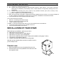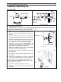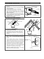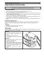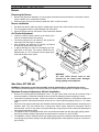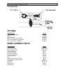
1
ULTRA FLAME
DIRECT VENT GAS STOVE
INSTRUCTIONS MANUAL
WARNING: If the information in these
instructions is not followed exactly, a fire or
explosion may result causing property
damage, personal injury or loss of life.
FOR YOUR SAFETY: Do not store or use
gasoline or other flammable vapours and
liquids in the vicinity of this or any other
appliance.
Installation and service must be performed
by a qualified installer, service agency or the
gas supplier.
WHAT TO DO IF YOU SMELL GAS:
•
Do not try to light any appliance.
•
Do not touch any electric switch; do not
use any phone in your building.
•
Immediately call your gas supplier from
neighbour’s phone. Follow the gas
supplier’s instructions.
•
If you cannot reach your gas supplier, call
the fire department.
THE INSTALLATION MUST CONFORM WITH LOCAL CODES OR, IN THE ABSENCE
OF LOCAL CODES, WITH THE CURRENT NATIONAL FUEL GAS CODE ANSI Z223.1
(USA) OR THE CURRENT CAN/CGA B149 INSTALLATION CODES (CANADA).
PLEASE KEEP THIS INSTRUCTIONS MANUAL
FOR FUTURE REFERENCE
000920/45046A
ULTRA FLAME DIRECT VENT GAS STOVE
1
TABLE OF CONTENTS
GENERAL INFORMATION.................................................................................................................................................... 2
WARNING.............................................................................................................................................................................. 2
TECHNICAL SPÉCIFICATIONS ............................................................................................................................................ 3
Dimensions........................................................................................................................................................ 3
Burner................................................................................................................................................................ 4
Gas Valve SIT 820 Nova mV ............................................................................................................................ 4
Pressure Adjustments ................................................................................................................................... 4
Available Wall Venting Kits ............................................................................................................................... 5
Available Options .............................................................................................................................................. 5
SELECTING TYPICAL INSTALLATION ................................................................................................................................ 6
Safety Notice ..................................................................................................................................................... 6
Positioning the Stove ........................................................................................................................................ 6
Clearance to combustibles................................................................................................................................ 6
Critical Length of Venting Pipes ........................................................................................................................ 7
Terminal Vent Location ..................................................................................................................................... 7
INSTALLATION OF YOUR STOVE ....................................................................................................................................... 8
Pedestal cover .................................................................................................................................................. 8
Installation of Wall Venting Kits......................................................................................................................... 9
Direct Vent Kit ............................................................................................................................................... 9
Direct Vent Kit for Corner Installation.......................................................................................................... 10
Direct Vent Kit for Basement Installation .................................................................................................... 12
Direct Vent Kit for Floor Installation............................................................................................................. 14
Gas Piping................................................................................................................................................... 16
Electrical Connections..................................................................................................................................... 16
Logs Installation .............................................................................................................................................. 17
Ember Kit Installation ...................................................................................................................................... 17
Bay Window Installation .................................................................................................................................. 17
OPERATION OF YOUR STOVE ......................................................................................................................................... 18
For your safety ................................................................................................................................................ 18
Lighting Instructions ........................................................................................................................................ 18
Shut down Instructions.................................................................................................................................... 19
Optional Blower ............................................................................................................................................... 19
Optional Wall Thermostat................................................................................................................................ 19
MAINTENANCE INSTRUCTIONS ....................................................................................................................................... 20
Yearly maintenance ........................................................................................................................................ 20
Burst Disc Replacement.................................................................................................................................. 20
Bay window ..................................................................................................................................................... 20
Cleaning ...................................................................................................................................................... 20
Repairing ..................................................................................................................................................... 20
Burner.............................................................................................................................................................. 21
Removing the Burner .................................................................................................................................. 21
Burner Installation ....................................................................................................................................... 21
Air Shutter Adjustment ................................................................................................................................ 21
Gas Valve SIT 820 mV.................................................................................................................................... 21
Maximum Pressure Adjustment, Altitude Installation.................................................................................. 21
Pilot Assembly................................................................................................................................................. 22
OPTIONS............................................................................................................................................................................. 22
REMPLACEMENT PARTS .................................................................................................................................................. 22
LIMITED WARRANTY ......................................................................................................................................................... 23
ULTRA FLAME DIRECT VENT GAS STOVE
2
GENERAL INFORMATION
The ULTRA FLAME DIRECT VENT GAS STOVE is a high-efficiency gas appliance with a maximum input
rating of 30 000 Btu/h (8,8 kW) with natural gas or 26,000 Btu/h (7,6 kW) with propane. It features an
adjustable millivolt valve and a constant pilot independent of any electrical source. Your appliance will
therefore continue to heat your house in the event of a power failure. You can set the height of the flame to
your liking by turning the adjusting knob.
For increased efficiency, we offer as an option a 130 CFM blower. Speed control, thermo-switch and electrical
wiring are pre-installed on your stove. Easy to hook up, your fan will therefore turn itself « ON » and « OFF »
automatically.
An optional thermostat is also available for automatic room temperature control.
This appliance must be connected to a venting system. Read these instructions and consult your local building
authorities before installing this appliance. Install the unit and its venting system only as described in these
instructions. Use only with Drolet Direct Vent Kit, supplied by manufacturer.
KEEP THESE INSTRUCTIONS FOR FUTURE REFERENCE
This gas stove has been tested by Intertek Testing Services according to CGA-2.22-M96 and CAN/CGA-2.17M91 for Canada and ANSI Z21.50-1996 and UL307B-1995 for USA.
It is mobile home approved. This appliance must be installed in accordance with the current Standard Mobile
Homes, CAN/CSA Z240 MR OR CAN/CSA Z240RV, RECREATIONAL VEHICLES or with the Manufactured
Home Construction and Safety Standard, Title 24 CFR, Part 3280, or when such a standard is not applicable,
the current Standard for Fire Safety Criteria for Manufactured Home Installations, Sites, and Communities,
ANSI/NFPA 501A or with the current Standard for RECREATIONAL VEHICLES, ANSI A119.2/NFPA 501C.
The unit can be installed in a range of altitude from 0 to 4 500 ft (0-1 370 m) in Canada. In USA see gas codes
for operating above 2000 ft.
WARNING
•
•
•
•
•
•
•
•
•
•
Installation should be done by a qualified installer.
Do not burn wood or any other material in this appliance.
Hot when in operation. Keep children, furniture, clothing and flammable material away
from the appliance.
Inform adults and children to the hazard of high surface temperatures and that they
should stay away to avoid burns or clothing ignition.
Young children should be supervised when they are in the same room as the appliance.
The appliance should be inspected before use and at least annually by a qualified
service person. More frequent cleaning may be required due to excessive lint from
carpeting, bedding material, etc.
It is imperative that the control compartments, burners and circulating air passageways
be kept clean.
Do not modify this appliance.
The openings in the gas stove pedestal should never be blocked.
Provide adequate accessibility clearances for servicing and proper operation.
ULTRA FLAME DIRECT VENT GAS STOVE
3
TECHNICAL SPÉCIFICATIONS
Dimensions
Dimensions
Height :
Width :
Depth :
Ceramic Glass
Front :
TOP VIEW
FRONT VIEW
29
26
23
in
in
in
18 3/16 in
462 mm
Sides :
5 1/16 in
129 mm
Weight :
140 lbs 64 kg
Color :
Metallic Black
Clearances to Combustibles
• Back :
1 po
25 mm
• Side :
14 po 355 mm
• Corner :
4 po
100 mm
• Top :
36 po 915 mm
• Floor :combustible Note 1
735 mm
920 mm
585 mm
x 15 15/16
x
405
x 15 15/16
x
405
in
mm
in
mm
Note 1 : Your stove has been successfully certified while installed on
a wood floor. Do not install your stove on carpet. Choose instead
ceramic tile or wood floor.
SIDE VIEW
ULTRA FLAME DIRECT VENT GAS STOVE
4
Burner
Maximum Input, BTU/h (kW)
Inlet Pressure INWC (kPa)
Manifold Pressure INWC (kPa)
Burner orifice, ∅ :
Injecteur du pilot. ∅ :
minimum :
maximum :
minimum :
maximum :
minimum :
maximum :
Natural Gas
20 000
(5,9)
30 000
(8,8)
5,0
(1,3)
7,0
(1,8)
1,8
(0,5)
3,5
(0,9)
36
51
Propane LP
20 000
(5,9)
26 000
(7,6)
11,0
(2,8)
14,0
(3,5)
7,0
(1,8)
10,0
(2,5)
52
30
Gas Valve SIT 820 Nova mV
Gas Valve :
Natural Gas
Model SIT 0.820.634
Nova mV
Propane LP
Model SIT 0.820.633
Nova mV
Your stove is equipped with a sophisticated gas control valve, which will give you a safe use of your appliance.
The gas control valve SIT 820 Nova mV operates without electricity due to the energy given by the pilot flame
and captured by the thermo-generator. (also called thermopile). The admission of the gas fuel to the burner is
done only under safe conditions.
Pressure Adjustments
• Adjustments to the valve assembly must be performed by a qualified service person.
• The appliance and its individual shutoff valve must be disconnected from the gas supply piping system
during any pressure testing of that system at test pressures in excess of ½ psi (3.5 kPa);
• The appliance must be isolated from the gas supply piping system by closing its individual manual shutoff
valve during any pressure testing of the gas supply piping system at test pressures equal to or less that ½
psi (3.5 kPa);
NATURAL GAS
The inlet supply or line pressure must be a minimum of 5 INWC and a maximum of 7 INWC. The orifice has a
#36 hole.
ELEVATION
INPUT RATING
0-4500 ft (0-1400m)
30 000 BTU/h (8.8 kW)
over 4500 ft (1400 m) +
30 000 BTU/h (8.8 kW) less 4% per 1000 ft (300 m)
or reduce manifold pressure by 0.25 INWC per 1000 ft (300 m)
GAZ PROPANE
The inlet supply or line pressure must be a minimum of 10.5” WC and a maximum of 12” WC. The orifice
has a #52 hole.
ELEVATION
INPUT RATING
0-4500 pi (0-1400 m)
26 000 BTU/h (7.6kW)
4500 pi (1400m)+
26 000 BTU/h (7.6kW) moins 4% par 1000 pi (300m)
or reduce manifold pressure by 1 INWC per 1000 ft
NOTE : The input rating should always be checked when first running this appliance. To do this, verify inlet
valve pressure and manifold pressure,. Adjust manifold pressure to meet values range as indicated in burner
characteristics table.
ULTRA FLAME DIRECT VENT GAS STOVE
5
Available Wall Venting Kits
Venting Kit for Direct Installation AC05506
Venting Kit for Corner Installation AC05507
DESCRIPTION
•
Outer pipe (∅ 8 in.) for admission of fuel-air in carbon
steel, black 24GA ;
•
Inner flexible pipe (∅ 5 in.) in aluminum allowing the
exhaust of the flue ;
•
Snorkel type vent terminal in galvanized steel.
DESCRIPTION
•
Outer pipe (∅ 8 in.) for admission of fuel-air in carbon
steel, black 24GA ;
•
Inner flexible pipe (∅ 5 in.) in aluminum allowing the
exhaust of the flue ;
O
•
45 elbow (∅ 8 in.)
•
Snorkel type vent terminal in galvanized steel.
Venting Kit for Floor Installation AC05502
Venting Kit for Basement Installation AC05509
DESCRIPTION
•
Outer pipe (∅ 8 in.) for admission of fuel-air in carbon
steel, black 24GA;
•
Inner flexible pipe (∅ 4 in.) in aluminum allowing the
exhaust of the flue;
O
•
2-90 elbow and straight pipes (∅ 8 in.) included ;
•
Small vent terminal in galvanized steel.
DESCRIPTION
•
Outer pipe (∅ 8 in.) for admission of fuel-air in carbon
steel, black 24GA ;
•
Inner flexible pipe (∅ 5 in.) in aluminum allowing the
exhaust of the flue ;
O
•
2-90 elbow and straight pipes (∅ 8 in.) included ;
•
Snorkel type vent terminal in galvanized steel.2
Available Options
Blower AC05529
•
Flow rate : 130 CFM (3.68m3/min)
O
O
•
Thermoswitch starting the blower at 110 F (43 C) and
O
O
stop it at 90 F (32 C)
•
Speed control (rheostat)
Thermostat AC05558
ULTRA FLAME DIRECT VENT GAS STOVE
6
SELECTING TYPICAL INSTALLATION
Safety Notice
•
•
•
•
Improper installation may result in a house fire. Follow installation directions. Installation must be
done in accordance with local building codes or, in the absence of local codes, with current
CAN/CGA B 149 installation codes for gas appliances (Canada) and current National Fuel Gas
Code ANSI Z223.1 (USA).
A qualified installer must do installation.
This gas stove must be vented outside.
This gas stove, when installed with optional blower or hand held remote, must be electrically
grounded in accordance with local codes or, in the absence of local codes, with the national
electrical code, ANSI/FPA 70, or the Canadian Electrical code, CSA C22.1.
Positioning the Stove
•
•
•
•
•
Always locate the stove as near as possible to an outside wall. Keep horizontal run of vent pipe as short
as possible;
Provide adequate clearances around air openings into the combustion chamber. Provide adequate
accessibility clearances for servicing and proper operation.
The ULTRA FLAME may be installed in a bedroom provided that all required clearances are met and a
wall thermostat is installed.
Never install the stove in a hallway or near a staircase as it may block the way in case of a fire
A gas appliance must not be connected to a chimney flue serving a separate solid-fuel burning
appliance.
Clearance to combustibles
Clearance between the stove and any combustible material must also be maintained while installing your
appliance.
CLEARANCE
Back (in)
1
Side (in))
14
Corner (in)
4
Top (in)
36
Front (in)
12
Pipe (in)
1
Floor
Combustible Note 1
Direct Installation
Corner Installation
Basement or Floor Installation
Note 1 :Your stove has been successfully certified while installed on a wood floor. Do not install your stove on carpet. Choose instead
ceramic tile or wood floor.
Clearance between wall and the pipe is 1". Do not install the vent pipe in an enclosed area or through an
insulated wall without a radiation shield ( # E-5710)
ULTRA FLAME DIRECT VENT GAS STOVE
7
Critical Length of Venting Pipes
The following table shows maximum length to be respected while
installing your appliance:
In conclusion:
• If you have no rise (Vertical run= 0 ft) :
The maximum horizontal run is 5 ft ;
• If you have a known horizontal run :
Minimum vertical run = Horizontal run – 5 ft ;
• If you have a vertical run shorter than 5 ft :
Maximum horizontal run = Vertical run + 5 ft.
• If you have a vertical run longer than 5 ft :
Maximum horizontal run = 10 ft.
Note : 1-90O elbow is equivalent to 5 ft of horizontal run ;
1-45O elbow is equivalent to 2,5 ft of horizontal run.
Terminal Vent Location
Your Ultra Flame stove vents through a vent terminal installed on the roof or on the outside of any exterior wall
of your house. Many restrictions apply to the vent terminal location that should be considered before locating
your stove. The following drawing presents a summary of most of these restrictions.
LEGEND
A. 12" Clearance above grade, veranda, porch, deck or balcony
B. 12" Clearance to window or door that may be opened
C. 12" Clearance to permanently closed window
D. 18" Vertical clearance to ventilated soffit located above the terminal within a horizontal distance of 2 feet (60 cm)
from the center-line of terminal (direct or corner installation)
24" Vertical clearance to ventilated soffit (Basement installation)
E. 12" Clearance to unventilated soffit, (straight out or corner installation)
24" Clearance to unventilated soffit, (Basement installation)
F. 12" Clearance to outside corner
G. 12" Clearance to inside corner
H. 36" clearance to each side of the centreline extended above the meter / regulator assembly to a maximum vertical
distance of 15ft (4.57M)
I. 36" clearance to service regulator vent outlet
J. 12" Clearance to non-mechanical air supply inlet to building or the combustion air inlet to any other appliance
ULTRA FLAME DIRECT VENT GAS STOVE
8
K. 72" Clearance to a mechanical air supply inlet
L. 84" Clearance above paved sidewalk or a paved driveway located on public property. A vent shall not terminate
directly above a sidewalk or paved driveway which is located between two single family dwellings and serves
both dwelling
M. 36" Clearance under veranda, porch, deck, or balcony. Only permitted if veranda, porch, deck, or balcony is fully
open on a minimum of 2 sides beneath the floor.
Local codes or regulations may require different clearances.
When the vent terminal is accessible, a certified guard shall be installed around the terminal. This guard is available as
an option, identified as part #E5480, for straight and corner terminals and #E5482 for the basement terminal
The vent terminal may not be recessed into the wall or siding.
The vent terminal shall not terminate:
•
Within 3 ft. of a building mechanical air supply.
•
Less than 12 inches from a perpendicular wall.
•
Under a window that pivots open.
In addition, in a structure with three walls and a roof, the vent terminal should not be installed if:
•
The minimum distance between the two sidewalls must be 72";
•
The roof exceed the walls by more than 24".
INSTALLATION OF YOUR STOVE
Before starting any installation, make sure you know :
Where do you run your gas line ;
What type of venting kit do you need (page 5) ;
Where do you run you’re your venting pipes ;
Where do you install the terminal vent in respect with installation code (page 7 and 8) ;
Clearances to combustibles (page 6) ;
Length of horizontal and vertical runs of venting pipes
Now that you have decided where and how to install your stove,
you are ready to start:
Pedestal cover
1. Slide the pedestal cover over the pedestal from the front.
2. Place the back cover on the pedestal cover and secure with
the supplied screws.
ULTRA FLAME DIRECT VENT GAS STOVE
9
Installation of Wall Venting Kits
Direct Vent Kit
VENT TERMINAL
RADIATION SHIELD
-min 1"
-max 60"
Direct Vent
Direct Vent Details
1. Move the stove to its position;
2. Install temporary a 8 in. section (4) to visualize where the opening to be done thru the wall. Center of the
opening should be at about 23 ½ “above the base of the stove;
Note: Horizontal run should have a slope of ¼ in per foot.
3. Make a 10-1/2" x 10-1/2" opening in the wall, 23-1/2"
inches in order to introduce the radiation shield thru
the wall;
4. Cut the radiation shield to length if necessary and
install as shown. Secure with four #10 1” wood screws;
10-1/2" X 10-1/2"
OPENING
5. Install the vent terminal (13) with 2 ½ screws (12). You
may want to remove the vent casing for easy access
and manipulation, Keep only in place the wall plate
6. Insert the 8 in. pipe into the round opening of the
interior black wall plate (7). Fix the insulation pad (9)
around the 8 in. pipe with the aluminum tape;
7. Keeping the insulation joint of the 8 in. pipe down,
insert it into the vent terminal wall plate;
8. Secure the 8 in. pipe to vent terminal wall plate with
the metal screw;
9. Fix finally the vent terminal wall plate with six 2 ½ in
screws (12).
10. Insert the 5 in. flexible pipe (3) into the 8 in. pipe and
fix it to the vent terminal casing. Use high temperature
silicone and one locking band to secure it in pace;
NOTE: All joints must be sealed with RTV silicone, 315°C.
(600°F) temperature resistance.
11. Install the vent casing and the cover in place
12. Seal around the terminal to prevent water leakage into
the house
CUT TO LENGTH
ULTRA FLAME DIRECT VENT GAS STOVE
10
13. Seal around the 8 in. pipe to prevent cold air to get into
the house.
14. Seal around the cover slots to avoid water infiltration
into the vent terminal;
15. Insert spring spacers into the 5 in. flexible pipe;
16. Put some high temp silicone on the stove’s 5 in.
flange. Insert one locking band on the 5 in. pipe and
insert it on the stove flange. Make sure seal is perfect.
Tight the locking band
17. Fix the 8 in. pipe to the stove with three metal screws.
18. Fix Seal around the 8 in. pipe to prevent cold air to
get into the house. your stove to the floor ;
19. Installation is now complete.
5" LOCKING BAND
SCREWS
8"RIGID A
5" FLEXIBLE FLUE PIPE
Direct Vent Kit for Corner Installation
VENT TERMINAL
45 O ELBOW
60" MAX
RADIATION SHIEL
VENT PIPES
Corner Installation
1. Move the stove to its position;
2. Install temporary a 8 in. section (4) to visualize where
the opening to be done thru the wall. Center of the
opening should be at about 23 ½ “above the base of
the stove;
Note: Horizontal run should have a slope of ¼ in per foot.
Corner Installation Details
3. Make a 10-1/2" x 10-1/2" opening in the wall, 23-1/2"
inches in order to introduce the radiation shield thru
the wall;
4. Cut the radiation shield to length if necessary and
install as shown. Secure with four #10 1” wood screws;
10-1/2" X 10-1/2"
OPENING
5. Install the vent terminal (13) with 2 ½ screws (12). You
may want to remove the vent casing for easy access
and manipulation, Keep only in place the wall plate;
6. Insert the 8 in. pipe into the round opening of the
interior black wall plate (7). Fix the insulation pad (9)
around the 8 in. pipe with the aluminum tape;
7. Keeping the insulation joint of the 8 in. pipe down,
insert it into the vent terminal wall plate;
CUT TO LENGTH
ULTRA FLAME DIRECT VENT GAS STOVE
11
8. Secure the 8 in. pipe to vent
terminal wall plate with the metal
screw;
9. Fix finally the vent terminal wall
plate with six 2 ½ in screws (12).
10. Insert the 5 in. flexible pipe (3) into
the 8 in. pipe and fix it to the vent
terminal
casing.
Use
high
temperature silicone and one
locking band to secure it in pace;
NOTE: All joints must be sealed with
RTV
silicone,
315°C.
(600°F)
temperature resistance.
11. Install the vent casing and the
cover in place
12. Seal around the terminal to
prevent water leakage into the
house
13. Seal around the 8 in. pipe to
prevent cold air to get into the
house.
14. Seal around the cover slots to
avoid water infiltration into the
vent terminal;
15. Insert spring spacers into the 5 in.
flexible pipe;
16. Use all necessary rigid sections to
meet your specific needs. Fix 8 in.
pipes together with metal screws;
5" LOCKING BAND
SCREWS
8"RIGID A
17. Put some high temp silicone on
the stove’s 5 in. flange. Insert one
locking band on the 5 in. pipe and
insert it on the stove flange. Make
sure seal is perfect. Tight the
locking band
18. Fix the 8 in. pipe to the stove with
three metal screws.
19. Fix Seal around the 8 in. pipe to
prevent cold air to get into the
house. your stove to the floor ;
20. Installation is now complete.
5" FLEXIBLE FLUE PIPE
ULTRA FLAME DIRECT VENT GAS STOVE
12
Direct Vent Kit for Basement Installation
1. Move the stove to its position;
2. Install temporary an 8 in.
section (4) to visualize where
the opening to be done thru the
wall. Center of the opening
should be at about 23 ½ “above
the base of the stove;
Note: Horizontal run should have a
slope of ¼ in per foot.
3. Make a 10-1/2" x 10-1/2"
opening in the wall, 23-1/2"
inches in order to introduce the
radiation shield thru the wall;
4. Cut the radiation shield to
length if necessary and install
as shown. Secure with four #10
1” wood screws;
5. Install the vent terminal (13)
with 2 ½ screws (12). You may
want to remove the vent casing
for
easy
access
and
manipulation, Keep only in
place the wall plate;
6. Insert the 8 in. pipe into the round
opening of the interior black wall
plate (7). Fix the insulation pad (9)
around the 8 in. pipe with the
aluminum tape;
7. Keeping the insulation joint of the 8
in. pipe down, insert it into the vent
terminal wall plate;
8. Secure the 8 in. pipe to vent terminal
wall plate with the metal screw;
Basement Installation
10-1/2" X 10-1/2"
OPENING
9. Fix finally the vent terminal wall plate
with six 2 ½ in screws (12).
10. Insert the 5 in. flexible pipe (3) into
the 8 in. pipe and fix it to the vent
terminal
casing.
Use
high
temperature silicone and one
locking band to secure it in pace;
NOTE: All joints must be sealed with
RTV
silicone,
315°C.
(600°F)
temperature resistance.
CUT TO LENGTH
ULTRA FLAME DIRECT VENT GAS STOVE
13
11. Install the vent casing and
the cover in place
12. Seal around the terminal to
prevent water leakage into
the house
13. Seal around the 8 in. pipe
to prevent cold air to get
into the house.
14. Seal around the cover slots
to avoid water infiltration
into the vent terminal;
15. Insert spring spacers into
the 5 in. flexible pipe;
16. Use all necessary
sections to meet
specific needs. Fix
pipes together with
screws;
rigid
your
8 in.
metal
17. Put some high temp
silicone on the stove’s 5 in.
flange. Insert one locking
band on the 5 in. pipe and
insert it on the stove flange.
Make sure seal is perfect.
Tight the locking band
5" LOCKING BAND
SCREWS
8"RIGID A
18. Fix the 8 in. pipe to the
stove with three metal
screws.
19. Fix Seal around the
pipe to prevent cold
get into the house.
stove to the floor ;
20. Installation
is
complete.
8 in.
air to
your
now
5" FLEXIBLE FLUE PIPE
ULTRA FLAME DIRECT VENT GAS STOVE
14
Direct Vent Kit for Floor Installation
1. Move the stove to its position;
2. Install temporarily an 8 in. section
(4) to visualize where the opening
is to be done thru the wall. Center
of the opening should be at about
23 ½‘’ above the base of the stove;
Note: Horizontal run should have a
slope of ¼ in per foot.
3. Make a 10-1/2" x 10-1/2" opening
in the wall, 23-1/2" inches in order
to introduce the radiation shield
thru the wall;
4. Cut the radiation shield to length if
necessary and install as shown.
Secure with four #10 x 1” wood
screws;
5. Install the vent terminal (13) with
2½ screws (12). You may want to
remove the vent casing for easy
access and manipulation, Keep
only in place the wall plate;
6. Insert the 8 in. pipe into the round
opening of the interior black wall
plate (7). Fix the insulation pad (9)
around the 8 in. pipe with the
aluminum tape;
7. Keeping the insulation joint of the
8 in. pipe down, insert it into the
vent terminal wall plate;
8. Secure the 8 in. pipe to vent
terminal wall plate with the metal
screw;
Floor Installation Details
10-1/2" X 10-1/2"
OPENING
9. Fix finally the vent terminal wall
plate with six 2 ½ in screws (12).
10. Insert the 4 in. flexible pipe (3) into
the 8 in. pipe and fix it to the vent
terminal
flange.
Use
high
temperature silicone and one
locking band to secure it in place;
NOTE: All joints must be sealed with
RTV
silicone,
315°C.
(600°F)
temperature resistance.
CUT TO LENGTH
ULTRA FLAME DIRECT VENT GAS STOVE
15
11. Install the vent casing and the cover in place
12. Seal around the terminal to prevent water leakage into the house
13. Seal around the 8 in. pipe to prevent cold air to get into the house.
14. Seal around the cover slots to avoid water infiltration into the vent terminal;
15. Insert spring spacers onto the 4 in. flexible pipe;
Use all necessary rigid sections to meet your specific needs. Fix 8 in. pipes together with metal screws;
16. Put some high temp silicone
5" LOCKING BAND
on the stove’s 5 in. flange.
Insert the 5’’ x 4’’ reducer
SCREWS
(17) on the stove flange. Slip
one locking band (2) on the 4
in. pipe and secure it to the
8"RIGID
reducer. Make sure seal is
perfect.
17. Fix the 8 in. pipe to the stove
with three metal screws.
18. Fix Seal around the 8 in. pipe
to prevent cold air to get into
the house. your stove to the
floor ;
19. Installation is now complete.
5" FLEXIBLE FLUE PIPE
A
ULTRA FLAME DIRECT VENT GAS STOVE
16
Gas Piping
•
Move the ULTRA FLAME to the desired position.
•
Mark the location for the gas inlet pipe and the
location where the vent pipes will go through the
wall. Remove the appliance.
•
Route a 3/8" minimum NPT iron pipe gas line to the
desired location.
•
Install a shutoff valve to the gas line. Tighten
securely using a pipe joint compound.
•
Check the gas line piping for leaks. Use a soap and
water solution.
CAUTION: Do not use open flame to check leaks.
Electrical Connections
If you wish to make a direct electrical connection to the blower without using the six-foot cord supplied, route a
120 volt, 60 Hz electrical power supply line to the same location. Remove the power cord and connect the
120V line as per the following procedure:
• Unscrew the speed control unit and pull a few inches away from the junction box
• Unscrew the two marr connectors attached to the cord (P) and the cord ground
• Remove the cord and route the supply line through the same holes
• Make the electrical connection with the same wires the cord was attached to
• Screw the ground wire to the junction box (G)
• Screw the speed control unit back in place
CONNECT THE POWER LINE TO THE SAME
WIRES THE CORD WAS CONNECTED TO (P)
P
G
P
JUNCTION BOX
SPEED CONTROL
If you prefer to use the six-foot cord supplied, just connect it to a 120V outlet.
ULTRA FLAME DIRECT VENT GAS STOVE
17
Logs Installation
1. Remove the front glass.
2. Locate the log grate in the retainers in the right
and left rear corners.
3. Place the rear log (1) against the rear log stop.
Make sure grooves under the log line up with the
grate.
4. Place logs 2 and 3 against the stops in the middle
of the grate. Again see that grooves in the bottom
of the logs line up with the grate.
5. Place log 4 into the grooves of logs 1 and 2.
6. Log 5 sits over log 1 and 3.
7. Put the glass front assembly back in place.
Ember Kit Installation
CAUTION: Blocking gas ports with rock wool will result in poor light-up performance and delayed
ignition.
1. Place some pieces of rock wool fibers approximately 1/2" large behind the front gas ports.
2. Never put too much of rock wool on the gas ports. The gas must pass through the burner easily.
3. Cover entirely the first row of the front gas ports. You may have more than one piece thick over the same
gas port.
4. Light the stove. Modify the configuration of the rock wool on the gas ports until you reach the desired
effect.
5. Make sure not to put too many pieces as this could result in an altered flame pattern and possible carbon
deposition on the logs.
Bay Window Installation
Installation
•
•
Un-installation
Put the front glass assembly back in position.
• Let the stove cool down for at least one hour.
Insert the hooks of all four clamps in the glass
• Open both side panels.
front slots.
• Tighten both top clamps simultaneously.
• Open the four clamps.
• Tighten both bottom clamps simultaneously.
• Close the side panels and install both decorative • Remove the front glass assembly.
trim pieces.
CAUTION:
Do not operate your stove without bay window or with broken glass.
ULTRA FLAME DIRECT VENT GAS STOVE
18
OPERATION OF YOUR STOVE
For your safety
CAUTION:
•
•
A qualified installer must perform installation of the appliance, venting, piping and adjustments.
During operation, this stove is hot. Do not touch. Keep children, clothing and flammable materials
away
• Hot when in operation. Keep children, furniture, clothing and flammable material away
from the appliance.
• Make sure your stove is in good condition. Verify that the bay window close perfectly, all controls works as
per specification. Vents must be in perfect condition.
• Make sure your stove has been fabricated in respect with the type of gas you are using. Refer to the rating
plate installed on the back of your stove.
• The appliance and its individual shutoff valve must be disconnected from the gas supply piping system
during any pressure testing of that system at test pressures in excess of ½ psi (3.5 kPa); The appliance
must be isolated from the gas supply piping system by closing its individual manual shutoff valve during
any pressure testing of the gas supply piping system at test pressures equal to or less that ½ psi ;
• Do not use this appliance if any part has been under water. Immediately call a qualified service technician
to inspect the appliance and to replace any part of the control system and any gas control, which has been
under water. Make sure that there are no obstructions in the air intake or venting system.
• Clear the immediate area of combustible materials, gasoline, and other flammable liquids and vapors.
• Make sure that the gas log is in its proper place.
Lighting Instructions
During the first few hours of operation the appliance will release an odor. This is caused by the burning off of
residual oils used in the manufacturing process and by the curing of the high heat paint. Open a window to get
fresh air inside the house. The ceramic glass window may require cleaning after this initial fire. Please read
the instructions on cleaning in the MAINTENANCE section before doing so.
First Lighting
WARNING : If you do not follow these lighting instructions exactly, a fire or explosion may result causing
property damage, personal injury, or loss of life.
• Open the pedestal cover front panel to reach the control.
• Make sure the gas control knob is turned to the "OFF" position. If it is not, press knob slightly and turn
clockwise 3 to the "OFF" position. Do not force the gas control knob. If the gas control was in the on
position you should wait 5 minutes before trying to re-light the stove.
• If you smell gas STOP and follow instructions on the COVER page.
• Locate the pilot on the left side Push in and turn gas control knob counterclockwise 4 to the "pilot"
position.
• Press gas control knob in and hold. Immediately push the red igniter button repeatedly until pilot flame
ignites. Continue holding in the control knob for 5 to 10 seconds, and then release it. If the pilot flame goes
out, repeat this step.
Note: you might have to push couple of times the igniter (red button) before getting a pilot flame.
• Push and turn gas control knob counterclockwise 4 to the "ON" position. The burner flame will light.
IMPORTANT NOTE:
The gas valve is equipped of a thermopile (thermo generator) and a thermocouple. The thermopile while
warm up by the pilot flame supplies the necessary energy to the operation of the gas control valve. As
long as there’s no flame failure, the valve let the gas flowing in the stove.
Let your stove cool down between two lightings: If you attempt to relight your appliance while the
thermocouple is still warm, the control valve won’t let the gas flow to the burner. Wait few minutes to cool
the thermocouple down.
ULTRA FLAME DIRECT VENT GAS STOVE
19
Shut down Instructions
To turn the burner OFF
•
Push in and rotate the gas control knob clockwise 3 to "PILOT" position. Do not force.
To turn the pilot OFF
•
Push in and rotate the gas control knob clockwise 3 to "OFF" position. Do not force.
Optional Blower
The blower control contains a variable speed switch and a thermal switch. When the stove is operating, the
thermal switch will turn on at 120° F, allowing the blower to operate. When the stove cools to 90° F, the
thermal switch turns off the blower in about 40 minutes. This prevents the blower from operating when the
stove is not in use.
The blower not only helps circulate air throughout the room, it also increases the heat transfert efficiency of the
ULTRA FLAME.
NOTE: Wiring, speed control and thermo switch are pre-install at the factory. Blower installation is quick and
simple.
Optional Wall Thermostat
REMOVE THE BLUE JUMPER BETWEEN TH & TPTH SCREWS ON THE GAS VALVE.
The optional wall thermostat will automatically keep your room at an even temperature. You need to choose a
convenient location for the thermostat. Remember that it should be at least 10 feet from the stove and away
from direct radiation of the fire. Run the correct gauge wire (see table) from the valve to the thermostat and
wire as shown in the diagram.
DISTANCE
20 pi
30 pi
40 pi
50pi
DIAMETRE
18GA
16GA
14 GA
12GA
To use your ULTRA FLAME using the wall thermostat, follow the lighting procedure and set the gas control to
the ON position. Simply set your wall thermostat to a comfortable temperature and the stove will do the rest.
ULTRA FLAME DIRECT VENT GAS STOVE
20
MAINTENANCE INSTRUCTIONS
TURN OFF THE GAS WITH THE SHUTDOWN VALVE AND DISCONNECT
THE ELECTRICAL POWER BEFORE SERVICING THE APPLIANCE.
Yearly maintenance
•
•
•
•
•
•
The venting system and the gas stove should be inspected at least once a year.
Remove the front glass and the logs and clean them if necessary.
The control compartment, air circulating passages, firebox, logs and burner should be cleaned at least
once a year by vacuuming or brushing.
Check the pilot flame to see if it is adjusted properly. Readjust the pilot flame if necessary (as described
below) or clean the pilot orifice if readjustment is not possible.
Check the burner for flame lifting or for unusual flame pattern. If necessary clean the burner orifice. For
more information, see “Adjustments” in the INSTALLATION section.
Keep the area clear and free from combustible materials, gasoline and other flammable vapors and
liquids.
Burst Disc Replacement
If the burst disc under the burner moves from its location, it must be put back in place into the silicone seal.
Make sure the switch is depressed all the way during the installation. Otherwise the appliance will not
operate.
ATTENTION
• Never glue or lubricate the disc to the silicone seal.
• Do not put any object under the disc.
Bay window
We have supplied your ULTRA FLAME with special ceramic glass, which will withstand the heat from the unit
without cracking. Be careful not to hit the glass.
Cleaning
•
•
•
•
Never clean this glass with abrasive cleaners ;
Use only a cleaner recommended by your
dealer.) ;
Never clean glass while it is still hot.
Do not operate the stove with the glass broken
or removed
Repairing
•
•
•
•
•
Ask your Drolet dealer to provide to you an
appropriate replacement glass.
Remove the bay window
Remove front as explained above. With a 5/16”
nut driver remove all nuts holding the glass
retainers. Carefully remove retainers and seal.
If the gasket is damaged, replace it with a
identical one.
To get a new gasket, refer to you DROLET
dealer.
ULTRA FLAME DIRECT VENT GAS STOVE
21
Burner
Removing the Burner
•
•
Remove the glass front assembly. Lift out the grate and hearth insert around burner. Unscrew the burner
from the bottom of the combustion chamber,
Slide the burner out from the ventury towards left. Get it out from the stove.
Burner Installation
•
•
•
Get the burner back in place and push it towards right until the main orifice enters into the ventury.
The o-ring gasket must be in place between the main orifice;
Screw the burner back into the bottom of the combustion chamber.
Air Shutter Adjustment
•
•
•
•
Loosen the screw of the air shutter on the ventury (3) in
order to increase/decrease the opening.
The factory setting for the air shutter is fully closed for
natural gas, and fully open for propane
After operating the appliance 30 minutes, the flames
should have turned a nice yellow color.
In higher altitudes you may find a smudging up of the
glass after a few days. The shutter should then be
adjusted open in 1/16” increments until the glass stays
clear and the flame turns yellow.
WARNING :
The main orifice (burner must be well
inserted into the ventury tube. Damages
during lighting could happened.
Gas Valve SIT 820 mV
WARNING: Adjustments to the valve assembly must be performed by a qualified service person.
The maximum manifold pressure is set at the factory at 3.5INWC for natural gas and 10.5INWC for propane.
Maximum Pressure Adjustment, Altitude Installation
•
•
•
•
•
Remove the manifold pressure adjustment cover. The gas control knob must then be removed using a
special screwdriver. Rotate and reinstall the knob so that the maximum pressure reading is correct
Locate the two pressure test taps. Check line pressure or manifold pressure by loosening the small screw
inside the tap with a flat-head screwdriver about one turn. Connect pressure gauge using a ¼” I. D. rubber
hose.
Ensure the line pressure falls within the allowable limits and adjust the manifold pressure according to the
elevation table. The pilot should have a strong blue flame, which engulfs the thermopile and the
thermocouple. If there is any yellow in the pilot flame tips, the gas flow must be reduced by adjusting the
pilot pressure adjustment screw.
The appliance and its individual shutoff valve must be disconnected from the gas supply piping system
during any pressure testing of that system at test pressures in excess of ½ psi (3.5 kPa);
The appliance must be isolated from the gas supply piping system by closing its individual manual shutoff
valve during any pressure testing of the gas supply piping system at test pressures equal to or less that ½
psi (3.5 kPa);
ULTRA FLAME DIRECT VENT GAS STOVE
22
Pilot Assembly
OPTIONS
DESCRIPTION
Millivolt Wall Thermostat
Blower
Direct Vent Kit
Direct Vent Kit Corner Installation
Direct Vent Kit Basement Installation
Direct Vent Kit Floor Installation
Part #
AC05558
AC05529
AC05506
AC05507
AC05509
AC05502
REMPLACEMENT PARTS
DESCRIPTION
5 logs set
Burner (natural gas)
Burner (Propane gas)
Orifice natural gas
Orifice propane gas
Pilot SIT natural gas
Pilot SIT propane gas
Thermocouple SIT
Piezo
Natural gas valve Nova SIT 820
Propane gas valve Nova SIT 820
Front glass
Side Glass
Speed Control
Thermoswitch
Part #
AC05791
SE09021NG
SE09021LP
9071
9071-01
49103
49106
49122
49128
49133
49126
SE7601-03
SE7601-04
44080
44044
ULTRA FLAME DIRECT VENT GAS STOVE
23
1700, rue Léon-Harmel, Québec (Québec) G1N 4R9
tel. : (418) 527-3060 fax : (418) 527-4311
e-mail : [email protected] web site : drolet .ca
LIMITED WARRANTY
The manufacturers warranty extends only to the original consumer purchaser and is not transferable. This warranty covers brand new
products only, which have not been altered, modified nor repaired since shipment from factory. Proof of purchase (dated bill of sale),
model name and serial number must be supplied when making any warranty claim to your Drolet Stoves & Fireplaces dealer
This warranty applies to normal residential use only. Damages caused by misuse, abuse, improper installation, lack of maintenance,
over firing, negligence or accident during transportation are not covered by this warranty.
This warranty does not cover any scratch, corrosion or discoloration caused by over firing, abrasives or chemical cleaners. Any defect
or damage caused by the use of unauthorized parts or others than original parts void this warranty.
An authorized qualified technician must perform the installation in accordance with the Instructions supplied with this product and all
local and national building codes. Any service call related to an improper installation is not covered by this warranty.
Returned products are to be shipped prepaid to Drolet Stoves & Fireplaces for investigation. If a product is found to be defective, Drolet
Stoves & Fireplaces will repair or replace such defect and reasonable transportation fees will be refunded. Repair work covered by the
warranty, executed at the purchaser domicile by an authorized qualified technician requires the prior approval of Drolet Stoves &
Fireplaces. Labour cost and repair work to the account of Drolet Stoves & Fireplaces are based on predetermined rate schedule and
must not exceed the wholesale price of the replacement part.
Drolet Stoves & Fireplaces at its discretion may decide to repair or replace any part or unit after inspection and investigation of the
defect. Drolet Stoves & Fireplaces may, at its discretion, fully discharge all obligations with respect to this warranty by refunding the
wholesale price of any warranted but defective parts
Drolet Stoves & Fireplaces shall in no event be responsible for any special, indirect, consequential damages of any nature, which are in
excess of the original purchase price of the product.
WARRANTY APPLICATION
DESCRIPTION
PARTS
LABOUR
Combustion chamber (weldings only)
5 years
5 years
Stainless baffle
5 years
1 year
Carbon Steel baffle
2 years
1 year
Gas Valve, piezo, thermopile, thermoswitch, burner
1 year
1 year
N/A
N/A
Ceramic glass (thermal breakage only)
5 years
N/A
Paint, gasket, blower, Blower thermoswitch and rheostat
1 year
N/A
Gold plating (tarnishing)
5 years
N/A
Logs
Shall your unit or a components be defective, contact immediately your Drolet Stoves & Fireplaces dealer. Prior to your call make sure
you have the following information necessary to your warranty claim treatment:
•
•
You name, address and telephone number;
Bill of sale, dealer’s name;
•
Serial number and model name as indicated on the
nameplate fixed to the back of your unit;
•
Nature of the defect and any relevant information.
Before shipping your unit or defective component to our plant, you must obtain from your Drolet Stoves & Fireplaces dealer
an Authorization Number. Any merchandise shipped to our plant without authorization will automatically be refused and
returned to sender.