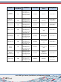
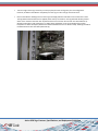
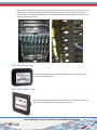
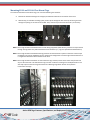
1
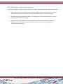
RF Code Active RFID Tags: Features, Specifications, and Deployment Guidelines Publication P/N 00660 REV05 Trademarks RF Code™ and the RF Code logo are trademarks of RF Code, Inc. All other product names are copyright and registered trademarks or trade names of their respective owners. Information in this document is provided solely to enable system and software implementers to use RF Code products. There are no express or implied copyright licenses granted hereunder to design or fabricate any integrated circuits or integrated circuits based on the information in this document. RF Code reserves the right to make changes without further notice to any products herein. RF Code makes no warranty, representation or guarantee regarding the suitability of its products for any particular purpose, nor does RF Code assume any liability arising out of the application or use of any product, and specifically disclaims any and all liability, including without limitation consequential or incidental damages. The user of this system is cautioned that any changes or modifications to this system, not e xpressly approved by RF Code, Inc., could void the warranty. Copyright Statement Copyright © 2008-2014 RF Code, Inc. All Rights Reserved. This document, as well as the hardware and firmware described therein, are furnished under license and may only be used or copied in accordance with the terms of such license. The information in these pages are furnished for informational use only, are subject to change without notice, and should not be construed as a commitment by RF Code, Inc. RF Code assumes no responsibility or liability for any errors or inaccuracies that may appear in these pages. Every effort has been made to supply complete and accurate information. However, RF Code assumes no responsibility for its use, or for any infringements of patents or o ther rights of third parties, which would result. RF Code, Inc. 9229 Waterford Centre Blvd. Suite 500 Austin, TX 78758 www.rfcode.com Active RFID Tags: Features, Specifications, and Deployment Guidelines 2 Table of Contents TRADEMARKS .............................................................................................................................................................. 2 COPYRIGHT STATEMENT .................................................................................................................................................. 2 TABLE OF CONTENTS........................................................................................................................................................ 3 REGULATORY AND COMPLIANCE INFORMATION ............................................................................................................. 4 INTRODUCTION AND OVERVIEW ..................................................................................................................................... 5 USING RF CODE TAGS IN DATA CENTERS ...................................................................................................................................... 6 GENERAL CLEANING PROCEDURES FOR RF CODE TAGS .................................................................................................................... 6 R-SERIES TAG FEATURES, SPECIFICATIONS, AND OPTIONS TABLE .................................................................................... 7 R-SERIES TAG – GENERAL USE AND DEPLOYMENT INSTRUCTIONS ................................................................................... 9 R100 IT ASSET TAG.................................................................................................................................................................. 9 R104-I IT ASSET TAG................................................................................................................................................................ 9 R110 FLEX-MOUNT TAG ......................................................................................................................................................... 11 R114-I FLEX-MOUNT TAG ....................................................................................................................................................... 11 R120 DOOR TAG ................................................................................................................................................................... 13 R130 DRY CONTACT TAG AND R131 IR-ENABLED DRY CONTACT TAG ............................................................................................. 15 R135 FLUID DETECTOR TAG ..................................................................................................................................................... 16 R140 BADGE TAG .................................................................................................................................................................. 19 R142-I BADGE TAG ................................................................................................................................................................ 19 R150 TEMPERATURE TAG ........................................................................................................................................................ 21 R155 HUMIDITY-TEMPERATURE TAG ......................................................................................................................................... 22 R151 TETHERED TEMPERATURE SENSOR TAG .............................................................................................................................. 27 TEMPERATURE SENSOR ACCURACY AND PRECISION ....................................................................................................................... 28 TEMPERATURE SENSOR PERFORMANCE IN TYPICAL DATA CENTERS .................................................................................................. 29 R160 DIFFERENTIAL AIR PRESSURE SENSOR TAG .......................................................................................................................... 30 OVERVIEW OF RF CODE PDU AND CDU SENSOR TAGS ................................................................................................................. 31 INSTALLING R170 PDU AND CDU TAGS..................................................................................................................................... 35 R170 PDU SENSOR TAG MOUNTING GUIDELINES........................................................................................................................ 36 R170 PDU SENSOR TAG OPERATIONAL NOTES ........................................................................................................................... 37 R180 4-20MA SENSOR TAG .................................................................................................................................................... 38 M-SERIES TAG FEATURES, SPECIFICATIONS, AND OPTIONS TABLE ................................................................................. 40 M-SERIES TAGS – GENERAL USE AND DEPLOYMENT INSTRUCTIONS .............................................................................. 41 M100 GENERAL ASSET TAG ..................................................................................................................................................... 41 M102-I INFRARED ASSET TAG .................................................................................................................................................. 41 M131 THIN TAG.................................................................................................................................................................... 41 M163 WRISTBAND TAG .......................................................................................................................................................... 43 M163-I WRISTBAND TAG ........................................................................................................................................................ 43 M172 DURABLE TAG .............................................................................................................................................................. 46 M172-I DURABLE TAG ............................................................................................................................................................ 46 M174-I IT ASSET TAG (SHOWN WITH RED TAB INSTALLATION TOOL) ................................................................................................ 48 M175 RUGGED TAG ............................................................................................................................................................... 53 DEPLOYING M-SERIES ASSET TAGS FOR DISTRIBUTED ASSET TRACKING ........................................................................ 53 Active RFID Tags: Features, Specifications, and Deployment Guidelines 3 Regulatory and Compliance Information FCC Compliance The system is design to operate with RF Code Active RFID Tags, operating at a frequency of 433.92 MHz, which have been certified or are in the certification process. These devices comply with Part 15 of the FCC rules. Operation is subject to the following two conditions: (1) These devices may not cause harmful interference, and (2) These devices must accept any interference received, including interference that may cause undesired operation. a. FCC ID: P6F2005433 for standard products with beacon intervals greater than, or equal to ten seconds. b. FCC ID: P6F433MHZ for security tags with beacon intervals less than ten seconds, where the total duration of transmissions does not exceed more than two seconds per hour for each transmitter. CE Compliance This is a Class A product. In a domestic environment, this product may cause radio interference, in which case the user may be required to take adequate measures. This equipment complies with the requirements relating to electromagnetic compatibility, EN 55022 Class A, the essential protection requirement of Council Directive 89/336/EEC on the approximation of the laws of the Member States relating to electromagnetic compatibility. WEEE Compliance Do Not Dispose of the Product with Municipal Waste. Special Collection/Disposal Required. Battery Statement RF Code warrants all tags to be free from defects in materials and workmanship for a period of one (1) year. Based on the ratings and specifications from the battery manufacturers, RF Code develops usage models to calculate the life of the active RFID Tags. Like all models, there are assumptions and approximations involved. The values are to be taken as engineering estimates and not as guarantees of performance. In most asset tag deployment scenarios, RF Code tags with a 10-second beacon rate have a useful life of 5-to-7 years. In most sensor tag deployment scenarios, RF Code tags will typically have a useful life of 3 or more years. Exposure to extreme temperatures will shorten the battery life of any sensor tag. Active RFID Tags: Features, Specifications, and Deployment Guidelines 4 Introduction and Overview RF Code Active RFID tags are battery-powered RF transmitters that attach to items that need to be tracked, located and identified. Every tag broadcasts its unique ID and a status message at a periodic rate (that is programmed at the factory). With a modular design and low price, tags provide an economical solution to a wide variety of problems. RF Code's patented communication protocols allow for very high tag densities. Large populations of tags can be deployed in highly scalable asset tracking environments. The read range for every RF Code Tag can be up to 300 feet, with the exception of the M131 Thin Tag, which has a read range of up to 150 feet. However, read ranges are dependent upon the deployment environment because of specific building materials and construction features, various obstructions, and other factors within the environment that can decrease read ranges. For more information, refer to the RF Code Support Knowledge Base Article: http://support.rfcode.com/customer/portal/articles/922012 RF Code tags operate at 433.92 MHz; they are one-way, transmit-only communicators. Patented RF Code communication protocols were designed to provide reasonable protection against harmful interference. Every RF Code tag is powered by a single coin cell (“watch”) battery (CR2032). Tags operate with a very low duty cycle and therefore have long battery lives (typically 5 years with a 10-second beacon rate). While most RF Code tags broadcast their status every 10 seconds*, each message is extremely short; therefore, each tag has an actual total transmission time of less than 10 seconds per day. However, tag broadcast frequency does vary slightly by tag type, as some send messages less often or more often. For more specific information about the characteristics of each tag model, refer to the tables of M-series and R-series tags. RF Code currently offers two series of Active RFID tags that work in conjunction with the RF Code line of Active RFID Readers and RF Code enterprise class software to meet many different tracking and monitoring needs. RF Code offers MSeries and R-Series Tags. These series offer several models that provide different alert features such as motion and tamper options. The M-Series tags operate at 433 MHz and are designed for general use in equipment and personnel tracking. The R-Series tags also operate at 433 MHz, but are specially-designed with sensors and/or specific form factors for IT assets. The R-Series tags are used for environmental monitoring in conjunction with RF Code Environmental Monitoring Solutions for Data Centers as well as for tracking rack-level equipment and for monitoring equipment racks and personnel with the use of RF Code M250 Readers. In addition to the two series of tags (M and R) available from RF Code, many tag models have an identical or similar version provision with infrared capabilities for use with RF Code Room and Rack Locators to provide even more precise determination of asset location. IR-enabled tags monitor their environment for incoming IR signals and periodically report both their own unique ID and IR location codes received from Room or Rack Locators. Since the location of IR tags is determined via the IR room code, there is no need for performing complicated signal strength calculations to determine tag location. Most tag models can be customized to support a broad range of integrated sensors in order to monitor tag status. Motion activated tags can be programmed to operate at two different beacon rates: slow (every 10 seconds) when the tag is stationary and faster (every 2 seconds) when the motion sensor is activated (to provide immediate notification when objects are moving). 2 second beacon rates are for use in safety and security applications. Tamper switches can be installed to trigger an alert if a tag is removed. IR tags are designed to be deployed in concert with RF Code IR Room Locators. IR-enabled tags monitor their environment for incoming IR signals and periodically report both their own unique ID and IR location codes. Motion activation allows the tag operate at 2 beacon rates: slow when the tag is stationary and faster when the motion sensor is activated. This provides a method for rapidly locating mobile assets with room-level accuracy. Active RFID Tags: Features, Specifications, and Deployment Guidelines 5 RF Code tags provisioned with IR or IR and motion and/or tamper sensors are identifiable in model names with a lowercase (i) appended to the model number, e.g., M102-i. Additional information about RF Code active tags is available online at: http://www.rfcode.com In general, the installation and/or application methods of tag deployment are the following: Adhesive application Lanyard mount Zip-tie mount Screw mount Using RF Code Tags in Data Centers Typical RFID applications include item tracking, inventory control, asset management and physical security. A specific example is the tracking of servers and network equipment in the data center. The impact of RFID on IT systems depends on three factors: the power of the transmission, the distance from the emission source, and the type of equipment in the path of the transmission. Transmission power is strictly regulated by governments to ensure that IT devices can coexist with RFID systems. Part 1 of the US FCC Part 15 mandates that a certified wireless device may not cause harmful interference. Moreover, most IT equipment is enclosed in a metal casing that is RF-opaque to UHF transmissions at 433 MHz. RF Code tag transmissions do not penetrate the metal casings of typical IT equipment. RF Code systems do not have any negative affect on IT equipment in a data center or in similar environments like telecommunications centers. Over two million (2,000,000+) RF Code tags have been deployed in the past decade, with more than 100,000 tags mounted directly on IT servers. There has never been a report of data loss or degradation in any storage or security device due to the presence and/or operation of RF Code tags and readers. General Cleaning Procedures for RF Code Tags RF Code’s Active RFID Tags are water-resistant to sustain repeated wipe-down procedures and they are robust with respect to daily cleaning with PDI sanitary wipes or similar products. Use a soft, slightly damp cloth, but avoid the use of window cleaners, solvents or abrasives. The enclosure and internal battery are rated for operation up to 70 degrees Celsius. Tags should not be subjected to elevated temperature cleaning cycles such as a dishwasher, pressure washer or autoclave. Cleaning instructions for specific tag models are provided in sections of this document specific to those tag models. Active RFID Tags: Features, Specifications, and Deployment Guidelines 6 R-Series Tag Features, Specifications, and Options Table The following table provides an overview of RF Code R-series (sensor) tags. Tag Use IT Asset Tag Tag Name/Model R100 IR IT Asset Tag R104-i Flex-Mount Tag R110 IR Flex-Mount Tag R114-i Door Tag R120 Dry Contact Tag R130 Dry Contact Tag with IR R131 Fluid Detector Tag R135 Badge Tag R140 IR Badge Tag R142 Temperature Tag R150 Dimensions Case width: 2.22 in. Case height: 0.35 in. Case depth: 4.96 in. Case weight: 0.46 oz. Case width: 2.22 in. Case height: 0.51 in. Case depth: 4.96 in. Case weight: 1.2 oz. Case width: 2.22 in. Case height: 0.30 in. Case depth: 1.72 in. Case weight: 0.4 oz. Case width: 2.22 in. Case height: 0.51 in. Case depth: 1.74 in. Case weight: 1.2 oz. Case width: 1.84 in. Case length: 1.35 in. Case height: 0.46 in. Case weight: 1.2 oz. Case width: 2.88 in. Case length: 1.7 in. Case height: 0.5 in. Case weight: 0.66 oz. Wire length: 12 in. Case width: 2.88 in. Case length: 1.7 in. Case height: 0.5 in. Case weight: 0.66 oz. Wire length: 8 ft. Case width: 2.88 in. Case depth: 1.7 in. Case height: 0.5 in. Case weight: 0.66 oz. Cable length: 9.84 ft. Case width: 2.15 in. Case depth: 3.4 in. Case height: 0.22 in. Case weight: 0.9 oz. Case width: 2.23 in. Case depth: 3.95 in. Case height: 0.28 in. Case weight: 1.4 oz. Case width: 2.22 in. Case depth: 1.71 in. Case height: 0.35 in. Case weight: 1.2 oz. Part Number Tag Features/ Options Mounting Options R100-0010 10s beacon Adhesive Mount R104-i000 10s beacon w/location changes, 50s beacon w/ no location changes Adhesive Mount R110-0010 10s beacon Adhesive Mount Zip-tie Mount R114-i000 10s beacon w/location changes, 50s beacon w/ no location changes Adhesive Mount Zip-tie Mount R120-0B10 10s beacon Adhesive Mount R130-0B10 10s beacon Adhesive Mount Screw Mount R131-iRDC 10s beacon Adhesive Mount Screw Mount R135-0B00 R135-0B50 10s beacon, no sensor film 10s beacon, w 50cm sensor film Adhesive Mount Screw Mount R140-0002 2s beacon Lanyard Mount R142-i3BN R142-i3RF 30s beacon, Beacon on demand Lanyard Mount R150-5B10 10s beacon Adhesive Mount Lanyard Mount Active RFID Tags: Features, Specifications, and Deployment Guidelines 7 Tag Use Tethered Temperature Tag Tag Name/Model R151 Humidity— Temperature Tag R155 Air Pressure Tag R160 PDU Tag – Raritan R170 CDU Tag – Server Technology R170 PDU Tag – Geist R170 PDU Tag – Emerson R170 PDU Tag – Schneider Electric R170 4-20mA Tag R180 Dimensions Case width: 2.88 in. Case depth: 1.7 in. Case height: 0.5 in. Case weight: 0.66 oz. Cable length: 9.84 ft. Case width: 2.22 in. Case depth: 1.74 in. Case height: 0.35 in. Case weight: 1.2 oz. Case width: 4.25 in. Case depth: 2.25 in. Case height: 1.0 in. Case weight: 3.25 oz. Case width: 1.84 in. Case depth: 1.35 in. Case height: 0.5 in. Case weight: 0.66 oz. Wire length: 7 ft. Case width: 1.84 in. Case depth: 1.35 in. Case height: 0.5 in. Case weight: 0.66 oz. Wire length: 7 ft. Case width: 1.84 in. Case depth: 1.35 in. Case height: 0.5 in. Case weight: 0.66 oz. Wire length: 7 ft. Case width: 1.84 in. Case depth: 1.35 in. Case height: 0.5 in. Case weight: 0.66 oz. Wire length: 7 ft. Case width: 1.84 in. Case depth: 1.35 in. Case height: 0.5 in. Case weight: 0.66 oz. Wire length: 7 ft. Case width: 4.25 in. Case depth: 2.25 in. Case height: 1.0 in. Case weight: 3.25 oz. Wire length: 8 ft. Part Number Tag Features/ Options Mounting Options R151-0010 10s beacon Adhesive Mount R155-5B10 10s beacon Adhesive Mount Lanyard Mount R160-0010 10s beacon Adhesive Mount Screw Mount R170-0B01 Specific to Raritan PDUs Adhesive Mount R170-0B02 Specific to Server Technology CDUs Adhesive Mount R170-0B03 Specific to Geist PDUs Adhesive Mount R170-0B04 Specific to Emerson PDUs Adhesive Mount R170-0B06 Specific to Schneider Electric/APC PDUs Adhesive Mount R180-0010 10s beacon Adhesive Mount Screw Mount Active RFID Tags: Features, Specifications, and Deployment Guidelines 8 R-Series Tag – General Use and Deployment Instructions R100 IT Asset Tag The R100 IT Asset Tag is designed for use with U-mounted racked assets. R104-i IT Asset Tag The R104-i Tag is designed for use with rack-mounted assets and should be deployed in concert with RF Code's A740 Rack Locators and A750 Room Locators. Mounting R100 and R104-i Tags To mount R100 and R104-I Asset Tags, follow these guidelines and instructions: • Place the tag directly on the surface of the asset; do not attach it to the bezel. • Mount all tags consistently on each type of asset. Active RFID Tags: Features, Specifications, and Deployment Guidelines 9 • Trim the tongue of the tag if necessary to more properly fit mount the tag with your rack configuration. However, do not trim the adhesive completely from the tag or it will no longer stick to the asset. • Remove the adhesive backing liner from the tongue and apply adhesive side down to the surface of the asset. The tag adhesive bonds when force is applied, rather than by air activation. The tag should be forcibly pressed down on the surface of the asset with 15 pounds of force for more than two seconds. The ideal adhesive application temperature range is 60°F (21°C) to 100°F (38°C). Application is not recommended if the surface temperature is below 50°F (10°C) because the adhesive becomes too firm to adhere readily. R104 tags should be installed with the IR lens side down (label side up). Active RFID Tags: Features, Specifications, and Deployment Guidelines 10 • Tags should be installed on an asset where the tag is located at least three inches away from the IR strip or side of the rack for use with the A740 Rack Locator. This will allow the tag to receive a maximum coverage from multiple IR LEDs. It will also help to prevent the asset tags themselves from blocking a significant amount of any IR LED’s transmission coverage. R110 Flex-Mount Tag The R110 Flex-Mount Tag is designed for flexible mounting on assets such as blade servers and tower equipment. R114-i Flex-Mount Tag R114-i IR Tag is designed for use with rack-mounted assets and is deployed in concert with RF Code's A740 Rack Locators and A750 Room Locators. Active RFID Tags: Features, Specifications, and Deployment Guidelines 11 Mounting R110 and R114-i Flex-Mount Tags To mount R110 and R114-I Flex Mount Tags, use one of the following two methods: A. Remove the adhesive backing liner and apply the adhesive side down to the surface of the asset. B. Alternatively, for a flexible mounting option, slide a zip-tie through the slot on the top of the tag and then through an opening on the asset to be tracked. Then, close the zip tie and trim the tail of it, if necessary. NOTE: R114-i tags should be installed with the lens side facing equipment (label side out), with the tie wrap inserted through the tag hole that is positioned furthest from the IR lens. (i.e.; tags lens positioned towards bottom). NOTE: R114-i tags should be installed with the tag placed at the same distance or plane in reference to the IR strips installed for use with the A740 Rack Locator. Optimal rack configurations will have tag mounted where there is a slight bend downward when attached to the asset. NOTE: R114-i tags should be installed on an asset where the tag is located, at least three inches away from the IR strip or side of the rack. This will allow the tag to receive a maximum coverage from multiple IR LEDs. It will also help to prevent the asset tags themselves from blocking a significant amount of any IR LED’s transmission coverage. Active RFID Tags: Features, Specifications, and Deployment Guidelines 12 R120 Door Tag The R120 Door Tag is designed for security applications monitoring room and rack doors. The tag is installed on the door or door frame. Once installed on the door frame the R120 will monitor and report the door status, enabling you to track attempts to access equipment within the racks. Mounting R120 Door Tags To mount R120 Door Tags, follow these instructions and guidelines: 1. Position the magnet on the frame of the door in proximity of where the R120 Door Tag will be positioned. 2. Remove the adhesive backing liner from the magnet or use the supplied screws to attach the magnet to the corner of the door frame. Active RFID Tags: Features, Specifications, and Deployment Guidelines 13 3. Remove the adhesive backing liner of the Door Tag and apply it to the corresponding corner of the door or equipment rack door. The tag adhesive bonds when force is applied, rather than by air activation. NOTE: The tag should be forcibly pressed down on the surface of the asset with 15 pounds of force for more than two seconds. The ideal adhesive application temperature range is 60°F (21°C) to 100°F (38°C). Application is not recommended if the surface temperature is below 50°F (10°C) because the adhesive becomes too firm to adhere readily. The R120 Door Tag must be mounted in such a way that the right or bottom edge of the tag is in close proximity to the magnet. Otherwise the tag may not be able to sense the magnet and could indicate the door is open when the door is actually closed. Right-Side Positioned Magnet: In this tag mounting configuration the magnet is positioned to the right of the R120 Door Tag within 1/2” of the tag in order to ensure proper readability and to avoid tag reporting errors. Install the R120 Door Tag on the inside of the entrance door, near the top of the door. Make sure the magnet is within 1/4” of the door tag, and near the indication arrows that are printed on the door tag label (Figure 3). Figure 3 - Door Tag and Magnet Position on Closet Door Active RFID Tags: Features, Specifications, and Deployment Guidelines 14 R130 Dry Contact Tag and R131 IR-Enabled Dry Contact Tag The R130 and R131 Dry Contact Tags are designed to be paired with a wide variety of dry contact sensors to allow real time monitoring of the sensors' state. Typical applications of the R130/R131 include but are not limited to use with fluid detectors, IR motion detectors, alarm relay contacts, moisture sensors, and door switches. When connected to a device with dry contact outputs, the tag will report the current open or closed state of the dry contact device. The R131 has an onboard IR sensor and is designed for tracking large, valuable assets that may periodically move between locations (such as laboratory freezers, bio freezers, and refrigerators). Dry contact devices have terminals that are either “closed” or “open” to indicate that a condition is normal. When something happens, such as an interruption of power, the dry contact terminals indicate an abnormal state for the device. Until now, the standard for monitoring this state change has been done with wired dry contact systems, with cables and wires linking the dry contact monitoring system to a power source. Such wiring is not only expensive, it’s rigid and if the equipment is moved, the cabling has to be redone. Once connected to a dry contact device, the battery-powered R130/R131 will monitor and report the open and closed state via RF transmissions. While in steady state, the tag will report the dry contact status once every 10 seconds. When the dry contact state changes, the tag will immediately broadcast three beacons at 0.5 seconds apart with the new dry contact status then return to beaconing the new condition once every 10 seconds. R130/R131 Tags have a minimum switching time of 200ms for both open and closed state transitions. Meaning, the tags are only intended to be used with devices that will be in the open or closed states for more than 2/10ths of a second. If the dry contact device switches from one state and back faster than 200ms the tag will not report the state change. IR-enabled tags are designed to be deployed in concert with RF Code’s IR Room Locators. These tags monitor their environment for incoming IR signals and periodically report both their own unique ID and IR location codes. This provides a method for rapidly locating mobile assets with room-level accuracy. Since location is determined via the IR room code, there is no need for deploying multiple overlapping readers or performing signal strength calculations or triangulation. The R130/R131 tag should be mounted on top of, or within a few feet of, the dry contact equipment. The R131 tag ships with an integrated 8-foot 24 AWG stranded cable that can be cut to length. Tags can be mounted using either the industrial-strength adhesive backing or by using the supplied plastic screw mount. The tag enclosures are impact resistant and temperature stable. R130/R131 tag battery life is typically 5 years. Active RFID Tags: Features, Specifications, and Deployment Guidelines 15 R135 Fluid Detector Tag The R135 Fluid Sensor Films attaches to an RF Code active RFID sensor tag via a three meter cord. This provides maximum flexibility in sensor tag placement. Information captured by the sensor tag is instantly broadcast, providing real-time monitoring and alerting about environmental conditions at a site. The R135 tag is designed to be deployed in a variety of challenging environments to monitor areas such as floor or ceiling mounted pipes, areas under or above a raised floor, for monitoring water delivery systems and chillers, and for use with air conditioning units and walls. R135 Fluid Tag Details The R135 Fluid Sensor Tag is a real-time liquid detection sensor that eliminates the need to wire or cable a data center for liquid leak detection capabilities. Combining thin-film technology with RF Code’s wire-free environmental monitoring technology, the sensor provides the ability to deploy liquid detection wherever vulnerabilities to conductive liquids threaten valuable assets. The unique qualities of this thin-film sensor make is easy to deploy this sensor in a variety of previously difficult to monitor areas such as: • Floor-mounted or ceiling-mounted pipes • Vulnerable floor areas including areas under or above a raised floor • Water delivery systems and chillers, including those found under raised floors in older data centers • Air conditioning units and walls Mounting the R135 Fluid Tag RF Code recommends using one of the mounting methods described below: R135 Fluid Tag Pipe Wrap Mounting In this mounting method, you will attach the R135 Fluid Detector Tag around the surface of a pipe or other rounded structure to monitor for fluid leaks. When doing so, follow these guidelines and instructions: • Apply the adhesive pad that was supplied to the back side of the sensor connector. • Remove the release liner from the back of the adhesive pad and position and press firmly to apply the sensor connector on the pipe. Active RFID Tags: Features, Specifications, and Deployment Guidelines 16 • • Remove the release liner from the back of the adhesive on the sensor film and wrap the fluid sensor film around the surface of the pipe with the top side (side with the holes) pointing away from the surface of the pipe. Ensure that you do not overlap the sensor film. • Secure the sensor film to the pipe by zip-tying around the sensor film and pipe at periodic intervals across the length of the sensor film. • Although the sensor film is flexible and allows for bending, take care to avoid creasing or pinching the sensor film as this can cause the film to not work properly. R135 Fluid Tag Wall Mounting When mounting the R135 Fluid Tag to a wall, follow these guidelines and instructions: • Position the R135 Tag on a wall near the pipe above the sensor connector. • Apply the adhesive pad that was supplied to the back of the tag. • Remove the release liner from the back of the tag and press firmly to mount the tag to the surface of the wall or use screws to screw the tag and mounting bezel to the wall. Tie-Wrap Mounting If mounting the tag in an area where it could potentially be bumped or snagged, you may want to use a strain relief method with the supplied tie-wrap and tie-wrap mount in order to position the sensor connector wire in such as way that if snagged, the wire will not be ripped from the tag. Flat Surface Mounting In this mounting method, you will attach the R135 Fluid Detector Tag to a flat surface such as a floor or wall. When doing so, follow these instructions and guidelines: • Remove the release liner from the bottom side of the sensor film and position the sensor film on the section or floor. Press firmly along the surface of the sensor film ensuring that there are no bubbles or kinks in the sensor film and that it is smoothly flattened against the floor or wall surface. • Apply the adhesive pad that was supplied to the back side of the sensor connector. Remove the release liner from the adhesive and position the sensor connector on the floor or wall. Press firmly to adhere the connector. Active RFID Tags: Features, Specifications, and Deployment Guidelines 17 • Run the connector wire up or along the wall or surface. Apply the adhesive pad that was supplied to the back side of the tag. Remove the release liner and press firmly to mount the tag to the wall or use screws to mount the tag using the screw mount bezel. • If mounting the tag in an area where it could potentially be bumped or snagged, you may want to use a strain relief method to position the sensor connector wire in such as way that if snagged, the wire will not be ripped from the tag. • Please note that the tag must be mounted in such a way where it will have an unobstructed proximity to the reader to ensure a correct detection beacon. For example, if mounting the sensor film under a raised floor, the tag will most likely need to be mounted above the raised floor in order for beacons to be detected. • The R135 Fluid Sensor is designed for detecting fluid in areas where fluid is not a normal occurrence. The sensor should not be used in any application where the sensor is normally in a wet state and is required to a report dry state as an alert condition. After the Fluid sensor has become wet it should be dried and retested for proper operation. Active RFID Tags: Features, Specifications, and Deployment Guidelines 18 R140 Badge Tag The R140 Badge Tag is specifically designed for security applications, tracking and monitoring personnel. The badge tag form factor can be easily clipped to a belt loop, lanyard, or shirt pocket. R142-i Badge Tag The R142-i3BN Badge Tag is intended to be deployed in concert with RF Code's A750 Room Locators. It is specifically designed for personnel tracking. The badge tag transmissions can be mapped in real-time to track personal movement, including entrances to and exists from controlled areas. The badge tag form factor makes it wearable around the neck with a lanyard or clipped on to a shirt pocket Attaching R140 and R142-i Badge Tags Attach the clip to the desired cutout (either on the top or side of the tag) and clip to clothing or attach to a lanyard that can be worn around the neck. Active RFID Tags: Features, Specifications, and Deployment Guidelines 19 NOTE: Although the badge tag has been tested and shown to work properly while carried in a wallet or pocket, the best read-range is achieved through using the lanyard mount, keychain clip or clothing clip method. The R142-I Badge Tag is ideal for deployment in hospitals when used with A760 Proximity Locators. The deployment configuration enables hospital administrators to know when health staff enter and exit rooms in order ensure that patients are seen in the most efficient and effective manner. When used with hand sanitation dispensers, the R142-I badge tag helps to ensure that hospital staff properly attend to personal hygiene in order to minimize the transfer of potentially harmful micro-organisms between rooms and patients. Figure: R142-I Badge Tag deployment with an A760 Proximity Locator to monitor entry and egress. Active RFID Tags: Features, Specifications, and Deployment Guidelines 20 Figure: R142-I Badge Tag deployment with an A760 Proximity Locator for sanitation and hygeine management. R150 Temperature Tag The R150 Temperature Tag monitors and reports the ambient temperature in its immediate environment. The R150 is designed to report temperature within + /- 1°C, (1.8°F), in environments ranging from -20°C to +70°C. It can be used to monitor the temperature within individual racks or to monitor the temperature in different areas of a data center. Active RFID Tags: Features, Specifications, and Deployment Guidelines 21 R155 Humidity-Temperature Tag The R155 Humidity-Temperature Tag monitors and reports the relative humidity and ambient temperature in its immediate environment. It is designed for use in environmentally-sensitive areas, such as IT data centers. This affordable sensor tag is mounted in an impact resistant polycarbonate enclosure with strong adhesive on the back of the case. The tag has reliable performance with an operating range from -20°C to +70°C and 0% to 95% RH. In temperature-controlled settings, such as offices and data centers, the sensor has an accuracy of +/- 0.3°C and +/- 2% RH (typical). Mounting R150 and R155 Sensor Tags on Assets or Walls When mounting R150 and R155 Sensor Tags, follow these guidelines and instructions: • If mounting on an asset or wall, ensure that the surface of the intended asset or wall is clean and dry. The tag should be forcibly pressed down on the surface of the asset with 15 pounds of force for more than two seconds. The ideal adhesive application temperature range is 60°F (21°C) to 100°F (38°C). Application is not recommended if the surface temperature is below 50°F (10°C) because the adhesive becomes too firm to adhere readily. • If mounting on a wall, take care to avoid mounting near windows as this will impact the tag’s ability to accurately monitor temperature. Avoid mounting the tag directly to a metal wall surface or in direct sunlight because this can affect read-range and temperature. • RF Code advises mounting the tag in a vertical orientation where the cut-out for the humidity sensor is vertical or mounted in such a way that the sensor is pointing down to prevent dust and debris from gathering in the cutout and creating humidity reporting errors. • Avoid mounting tags close to the ground as this may negatively impact read-range. Mounting R150 and R155 Sensor Tags on Racks To mount this tag in or on a rack, use one of the recommended mounting positions discussed below. NOTE: The R150 Rack Temperature Tag and the R155 Rack Humidity-Temperature Tag must be mounted in a position that will allow the sensor on the tag to monitor the temperature of the surrounding area of the assets that you would like to monitor. • To mount this tag on the door of a rack, remove the release liner of the adhesive backing of the temperature tag and press the tag firmly into place centered on the outside of the rack door. Active RFID Tags: Features, Specifications, and Deployment Guidelines 23 • To mount this tag in a using a zip-tie, you will need to have a lanyard bezel (optional). Slide the zip-tie through the lanyard bezel and find and appropriate place on the outside of the rack to secure the end of the zip-tie. NOTE: For more information on deploying R150 and R155 in a data center for environmental monitoring, refer to the following RF Code Support Knowledge Base article and document here: http://support.rfcode.com/customer/portal/articles/976954 Installing Sensor Tags in Network Closets For best read range, mount sensor tags at least five (5) feet from the floor and so they are not shrouded by metal, i.e., do not install sensor tags inside equipment racks, such as half-way from front to back or on enterprise computing equipment within the racks. An example minimal server room deployment is shown below: A. R155 Temperature-Humidity tags (A) are on the outside of equipment racks to monitor equipment intake and exhaust air. B. The R150 Temperature Tag (B) is placed to measure AC supply temperature. C. The R120 Door Tag (C) is mounted on the inside of the room entrance door to monitor unauthorized room access. D. The reader (D) is mounted on the cable tray between the racks being monitored. Active RFID Tags: Features, Specifications, and Deployment Guidelines 24 Figure: Minimal Server Room Tag Deployment for Environmental Monitoring B D C A A Install one R155 Temperature-Humidity Tag on the front side and one on the rear side of the equipment rack, or one sensor each on the front of rack containing critical equipment. If the racks have mesh doors, install the tag on the outside of the rack door. If the racks do not have doors (e.g., open racks or two-post racks), affix the tag anywhere near the IT equipment about five (5) feet above the floor. Affix the tags using the adhesive pads or the zip-ties and the lanyard mounts included in the bundle. NOTE: Do not affix the sensor tags to the IT equipment directly. Install one R150 Temperature Tag near the AC supply for the room, preferably in the air stream, or mount it in another area of the room where you want to monitor ambient air temperature. Sensor Tag Deployment in Data Centers to Monitor RCI When placing sensor tags in a data center in order to monitor RCI, follow these guidelines: Attach your tags to the outside of rack doors using either the attached adhesive or optionally the lanyard bezel and a zip tie that is included with the tags. The former method (using adhesive) allows easier replacement of the sensor battery when necessary and requires a smaller footprint. The latter method (using the lanyard bezel) is often just a personal preference of data center managers. With both methods, attaching the sensor tags to the outside of the rack doors provides the best read range. For RCI metrics, RF Code’s minimum recommendation is that you place at least three temperature tags on the front (top, rd middle, and bottom) of every third (3 ) rack door. However, for the most accurate and granular data, you should place three temperature tags on the front (top, middle, and bottom) of each and every rack. If the racks have no doors, attach the sensors to the inside wall of the rack. Figure: Three sensors (depicted as blue rectangles within red frames) mounted on the outside of every rack door. Active RFID Tags: Features, Specifications, and Deployment Guidelines 25 Figure: Three sensors (depicted as red rectangles) mounted on the inside of every third rack. Active RFID Tags: Features, Specifications, and Deployment Guidelines 26 Figure: An R155 temperature-humidity sensor mounted on the inside of a rack (left side of photo) near an R104-I IT Asset Tag (right side of photo) An RF Code best practice is to place temperature sensors at the top and bottom and a temperature-humidity sensor in the middle of the rack door. While not specifically necessary for RCI metrics, using temperature-humidity tags gains you visibility to humidity levels as well as to heat in the server racks and rows, which further enhances your ability to monitor and manage your data center environment. NOTE: Do not mount tags on hot surfaces, such as directly on a reader or on a server chassis; doing so can cause them to report inaccurate data. R151 Tethered Temperature Sensor Tag As an alternative to using the R150 Temperature Sensor Tag, the R151 form factor can be deployed in environments where the RF transmitter (tag) module is mounted in open space while the temperature sensor is installed inside RFblocking enclosures such as a metal ductwork or refrigerators. Mounting is easy and flexible; the tethered sensor can be routed into difficult to reach places, such as above a suspended ceiling or inside HVAC air ducts. Active RFID Tags: Features, Specifications, and Deployment Guidelines 27 Temperature Sensor Accuracy and Precision The following table shows the temperature sensor accuracy for typical use and over the entire supported temperature range for R150, R151, and R155 sensor tags. Temperature Sensor Precision Table Sensor Accuracy Temperature Sensor R150-5B10 Typical Range of Use Tethered Temperature Sensor R151-0010 Typical Range of Use ± 1.0° F Entire Supported Range ± 1.5° F Range (Fahrenheit) Range (Celsius) +40° to +140° +5° to +60° -4° to +158° -20° to +70° ± 2.0° F +14° to +185° -10° to +85° Entire Supported Range ± 4.0° F -67° to +212° -55° to +100° ± 0.4° F Humidity & Temperature Typical Range of Use Sensor R155-5B10 Entire Supported Range ± 2.0° F +50° to +140° +10° to +60° -4° to +158° -20° to +70° Temperature Sensor Calibration RF Code R150, R151 and R155 sensor tags have temperature-sensing components that are calibrated at the factory during the manufacturing process. These are silicon-based chips that don’t require field calibration or re-calibration over time. As the ambient temperature moves toward the extremes, sensor accuracy decreases slightly. The chart below illustrates this concept. Active RFID Tags: Features, Specifications, and Deployment Guidelines 28 The precision of the reported temperature data is also important. Temperature sensor data is handled by multiple RF Code components as part of the overall solution that includes RF Code Readers and RF Code software (Zone Manager and Asset Manager). The following table shows the data precision for each product. Precision at the Reader Default Precision in the Software* Temperature Sensor R150-5B10 0.06° C 0.1° C Tethered Temp Sensor R151-0010 0.50° C 0.5° C Humidity & Temp Sensor R155-5B10 0.04° C 0.1° C Sensor NOTE: Temperature precision can be controlled in the RF Code software via configuration settings to allow for less precision and therefore reduce the number of data points and data storage needed. Temperature Sensor Performance in Typical Data Centers Data center temperatures typically range from about 60° to 110° F (15° to 45° C) with a relative humidity range of 30% to 60% RH. In this environmental range, the sensors for the R150, R151 and R155 deliver their best, most accurate performance. This is true because the calibration coefficients are selected to ensure the most accurate readings in this specific range. The most accurate sensor is the R155 Humidity & Temperature Sensor that provides better than one quarter of one degree Celsius accuracy in the typical data center temperature range, including allowance for quantization error. Sensor Product Accuracy (typical) Ambient Range Accuracy (typical) Temperature Sensor R150-5B10 ± 0.47°F Temperature Sensor R150-5B10 ± 0.26°C +10°to +60°C ± 0.26°C Tethered Temperature Sensor R151-0010 ± 1.08°F +50°to +104°F ± 1.08°F Tethered Temperature Sensor R151-0010 ± 0.60°C +10°to +40 C° ± 0.60°C Humidity & Temperature Sensor R155-5B10 ± 0.41°F +50°to +140°F ± 0.41°F Humidity & Temperature Sensor R155-5B10 ± 0.23°C +10°to +60°C ± 0.23°C Humidity & Temperature Sensor R155-5B10 ± 2% RH 10% to 90% RH at 25° C ± 2% RH +50°to +140°F ± 0.47°F Active RFID Tags: Features, Specifications, and Deployment Guidelines 29 R160 Differential Air Pressure Sensor Tag The R160 Differential Air Pressure Sensor monitors and reports the differential air pressure reading between two points. It is typically installed under raised floors in data centers or in critical areas in hospitals where positive/negative air pressure is needed. R160 Air Pressure Tag Details The R160 Differential Air Pressure Sensor is used to measure air pressure difference above vs. below a raised floor, in a room vs. hallway (patient room monitoring), or between other areas in a data center. It reports its unique ID along with the sensor data observed by the tag to an RF Code fixed reader and then to the RF Code software stack (first to Zone Manager and then to Asset Manager). It includes 8 feet of flexible tubing to achieve physical separation between the +/- sensor terminals. The R160 sensor can be mounted with strong adhesive on the back of the case, or via hardware/screws or zip-ties through the mounting holes. Mounting R160 Tags When mounting R160 Air Pressure Tags, follow these instructions and guidelines: 1. Mount the R160 tag using provided adhesive pads or by securing with screws or zip-ties (not provided). 2. Attach the plenum pressure tube to the Plenum Pressure Tube Port indicated by a + symbol on the tag (or the “top” tube port). Plenum Pressure Tube Port Room Pressure Tube Port 3. Extend the tubing inside the plenum space. 4. Secure the end of the tubing using provided zip-ties so that air-flow doesn’t cause movement of the tubing, which can cause inconsistent sensor readings. Active RFID Tags: Features, Specifications, and Deployment Guidelines 30 Overview of RF Code PDU and CDU Sensor Tags RF Code offers PDU and CDU sensor tags for specific families of PDUs and CDUs offered by our partners. The following sections offer some specific Instructions and guidelines for these similar configurations. All power data collected from the rd PDU by the sensor tag flows to the RF Code readers, then to Zone Manager, and finally to Asset Manager and other 3 party applications. Tags connect to the PDU/CDU via an integrated 7-foot cable with an RJ-12 or RJ-45 connector, as appropriate. Powered by a replaceable coin cell battery, the R170 tag will perform reliably in any data center environment (the tag’s specified operating temperature range is -20 to +70 degrees Celsius). R170 tag cases are impact resistant and temperature stable. The R170 tag operates with a very low duty cycle that translates to long battery life (typically > 5 years). Featuring a low-battery alert, the tag will continue to report PDU operational data for at least three months following this alerting. Each tag broadcasts its unique ID and a portion of the PDU data once every 10 seconds using RF Code’s patented communication protocol. The Asset Manager software presents all of the collected power parameters and computes additional attributes from this data to provide a complete picture of power utilization. Power attributes can be visualized via live table and map views, interactive graphing, and scheduled reports and graphs. R170 PDU Sensor Tags only receive information from the PDUs. The tags do not allow any commands to be received by the unit, hence no outlet switching or other actions are possible through the tag. This means the RF Code wireless solution does not compromise power security. Active RFID Tags: Features, Specifications, and Deployment Guidelines 31 The following illustration depicts the architectural framework for RF Code software and PDU Sensor Tag hardware. As of January 2014, RF Code sells five (5) different R170 sensor tags for various power distribution units (PDUs) and cabinet power distribution units (CDUs) manufactured by the following partner companies: Emerson - Liebert MPX PDUs shipped with an RPC-1000 module and Liebert MPH PDUs shipped with an embedded RPC-1000. Geist - The satellite current monitoring family of PDUs. Raritan - The PX family of Raritan PDUs. ServerTech (STI) - Smart and Switched CDUs with PIPS (Per Inlet Power Sensing) and with or without POPS (Per Outlet Power Sensing). Schneider Electric - APC 8xxx series PDU’s NOTE: If you manufacture or sell a line of PDUs or CDUs that are not represented, please contact RF Code Professional Services for information regarding future opportunities to integrate with RF Code PDU and CDU sensor tags. Active RFID Tags: Features, Specifications, and Deployment Guidelines 32 R170 PDU Tag for Emerson The R170 PDU Tag for Emerson receives data published by Emerson Liebert MPX PDUs that ship with an RPC-1000 module and Liebert MPH PDUs that ship with an embedded RPC-1000. R170 PDU Tag for Geist The R170 PDU Tag for Geist receives data published by Geist PDUs in the satellite current monitoring family. R170 PDU Tag for Raritan The R170 PDU Tag for Raritan receives data published by Raritan PDUs in the PX family via the PDU’s Sensor port. Active RFID Tags: Features, Specifications, and Deployment Guidelines 33 R170 CDU Tag for Server Technology The R170 CDU Tag is compatible with Server Technology's Smart and Switched CDUs with PIPS (Per Inlet Power Sensing) and with or without POPS (Per Outlet Power Sensing). R170 PDU Tag for Schneider Electric The R170 PDU Tag for Schneider Electric receives data published by the 8xxx series APC PDU’s running firmware version 6.0.9 or higher. The tags periodically report their unique ID, the PDU model number, serial number, and PDU operational values including: - Connected/disconnected status Active power Apparent power Data collection start time Detailed PDU outlet and phase data Breaker data Line feed data Active RFID Tags: Features, Specifications, and Deployment Guidelines 34 Installing R170 PDU and CDU Tags To integrate the R170 PDU Sensor Tag with RF Code hardware and software (Zone Manager and Asset Manager), perform the following steps: 1. If you have not already done so, install the PDU in your enterprise hardware rack and then power it on. 2. If you have not already installed an RF Code Reader, please do so. NOTE: For information about installing RF Code Readers, please refer to the user manual for your reader, which is available on the CD that came with the reader or on the RF Code Support website: http://support.rfcode.com/customer/portal/articles/722910 3. If you have not already configured the RF Code Reader, please do so. NOTE: For information about configuring the reader, please refer to the user manual for the reader as well as to the user manual for the Reader Configuration Utility, both of which are available on the RF Code Support website: http://support.rfcode.com/customer/portal/articles/722910 4. Connect the R170 PDU Sensor Tag (illustrated directly below) to the PDU by plugging the cable attached to the sensor tag into the RJ-12 (or RJ-45, as appropriate) Out port (jack) on the PDU Active RFID Tags: Features, Specifications, and Deployment Guidelines 35 NOTE: Depending on the model of your PDU, the location and/or label of the port may be different; if so, please refer to the PDU user guide for the specific model in order to locate the proper port. 5. Mount the R170 PDU Sensor Tag according to the instructions presented below in the Mounting Guidelines section. R170 PDU Sensor Tag Mounting Guidelines The following guidelines will help to ensure that you mount the R170 Sensor Tag for optimal functioning. Mount the R170 Sensor Tag on the outside and near the top or above the IT rack where the PDU is installed; this helps to reduce interference with the radio frequency signal that can be caused by metal objects and structures. Remove the release liner from the back of the tag and press firmly to mount the tag to an upper exterior surface of the rack. To help prevent potential problems that could result from the tag being bumped or snagged, employ a strain relief method using the supplied tie-wrap and tie-wrap mount. Active RFID Tags: Features, Specifications, and Deployment Guidelines 36 R170 PDU Sensor Tag Operational Notes The following notes about the general operating characteristics of PDUs and PDU tags should be taken into consideration: Allow at least two hours for power information to become available in the RF Code software due to the time delay inherent in collection and transmission of data, which helps to ensure its accuracy and usability. Missed beacons will cause further time delays in the reporting cycle so they should be eliminated as much as possible by proper positioning of the tags. High levels of noise and/or tag densities in the deployment environment may require the installation of additional readers in order to assure successful delivery of data from the R170 to Zone Manager and subsequently to Asset Manager. Active RFID Tags: Features, Specifications, and Deployment Guidelines 37 R180 4-20mA Sensor Tag The R180 4-20mA Sensor Tag is designed for deployment with industrial process control equipment, devices, and sensors that use 4-20mA current loops. This enables wireless transmission of industry-standard 4-20mA sensor readings for specialty and industrial applications. R180 4-20mA Sensor Tag Details The 4-20 mA current loop is a common method of relaying sensor information in monitoring applications with a need for analog sensors. The 4-20 mA sensor is a device used to measure physical parameters (such as temperature, pressure, speed, liquid flow rates), with 4 mA representing the lowest end of the sensor range and 20 mA representing the highest sensor reading. The R180 Sensor Tag allows the 4-20 mA monitoring data to flow over the RF Code radio frequency infrastructure. Data transmitted from the sensor tags is captured by the RF Code reader infrastructure and relayed to the rd RF Code software (Zone Manager/Asset Manager) or into other 3 -party applications. The 4-20 mA current loop readings can be visualized in Asset Manager via: Live table and map views Interactive graphing Scheduled reports and graphs Alerting and thresholding Active RFID Tags: Features, Specifications, and Deployment Guidelines 38 These tags report their own unique ID and a portion of the 4-20 mA loop current value once every 10 seconds using RF Code’s patented communication protocol; this results in three (3) sensor readings per minute. 4-20 mA supported specifications: 1.25 uA resolution ±0.5% accuracy 100 ohm resistance Loop supply not included; the sensor must provide the power (or a separate power supply is required) The R180 ships with an 8-foot 24 AWG stranded cable that can be cut to fit or spliced. Powered by three (3) field-replaceable coin cell batteries, the R180 tag will perform reliably in an operating temperature range from -20 to +70 degrees Celsius. R180 tag enclosures are impact resistant and temperature stable. The R180 tag operates with a low duty cycle that translates to long battery life (typically > 5 years). Featuring a low-battery alert, the tag will continue to report 4-20 mA data for at least three months following this alert. Features: 4-20 mA wired interface via replaceable 8-foot insulated cable (24 AWG stranded) Adhesive mounting options for the tag and cable, making it easy to install the tag for maximum RF propagation Tag relays 4-20 mA payloads for upstream compiling and interpretation in the software stack Standard reporting interval of 3x per minute; optional custom firmware configurations to adjust communication and beacon rates for specific applications Estimated 5-year battery life with user-accessible / replaceable coin cell batteries Modular cable that is easy to install and to cut to length, with a binding connector to reduce the chance for accidental unplugging Mounting and Configuring R180 Tags When mounting R180 4-20mA Sensor Tag, follow these instructions and guidelines: 1. Mount the R180 tag using provided adhesive pads or by securing with screws or zip-ties (not provided). Attach the tag to the top of equipment to ensure a clear RF signal path in metal-dense environments. 2. Optionally cut the 8 ft. cable to desired length. 3. Secure wiring using zip-ties to provide a strain-relief and prevent inadvertent unplugging of the sensor. To configure the 4-20mA Sensor Tag in RF Code Zone Manager or Asset Manager, please refer to the following knowledge base articles on the RF Code support site: http://support.rfcode.com/customer/portal/articles/1412153-configure-4-20ma-tags-in-zone-manager http://support.rfcode.com/customer/portal/articles/1412152-configure-4-20ma-in-asset-manager Active RFID Tags: Features, Specifications, and Deployment Guidelines 39 M-Series Tag Features, Specifications, and Options Table Tag Name/Model Tag Use General Purpose Asset Tag M100 IR Asset Tag M102-i Thin Asset Tag IR Wristband Tag IR Durable Tag Tamper-Enabled IR Asset Tag Rugged Tag Case length: 1.84 in. Case width: 1.35 in. Case height: 0.46 in. Case weight: 1.20 oz. Case length: 1.84 in. Case width: 1.35 in. Case height: 0.46 in. Case weight: 1.20 oz. Part Number Tag Features/ Options M100-0002 2-second (2s) beacon M100-0010 10-second (10s) beacon M100-M000 10s beacon, 2s motion alert M100-T00 10s beacon, 2s tamper alert M102-iM00 10s beacon, 2s motion alert Mounting Options Screw Mount Lanyard Mount Adhesive Mount Magnet Mount Screw Mount Lanyard Mount Adhesive Mount Magnet Mount M102-iMT0 10s beacon, 2s motion alert, 2s tamper alert M131-0025 2.5s beacon M131-T025 2.5s beacon, 2s tamper alert M163 Case length: 1.854 in. Case width: 1.890 in. Case height: 0.553 in. Case weight: 0.500 oz. M163-0002 2s beacon Wristband Mount M163-i Case length: 1.854 in. Case width: 1.890 in. Case height: 0.553 in. Case weight: 0.500 oz. M163-iM00 10s beacon, 2s motion alert Wristband Mount M172-iM00 10s beacon, 2s motion alert M172-i Case length: 1.330 in. Case width: 1.770 in. Case height: 0.441 in. Case weight: 0.520 oz. M172-iMT0 10s beacon, 2s motion alert, 2s tamper alert M174-iT00 10 sec/50 sec beacon M175-0010 10s beacon M131 Wristband Tag Dimensions Case length: 2.040 in. Case width: 1.370 in. Case height: 0.228 in. Case weight: 0.500 oz. M174-i Case length: 1.562 in. Case width: 1.266 in. Case height: 0.454 in. Case weight: 0.376 oz M175 Case length: 2.510 in. Case width: 1.485 in. Case height: 1.000 in. Case weight: 1.800 oz. Adhesive Mount Adhesive Mount M175-M000 10s beacon, 2s motion alert Mounting strip (sold separately) Clip Mount Adhesive Mount Active RFID Tags: Features, Specifications, and Deployment Guidelines 40 M-Series Tags – General Use and Deployment Instructions M100 General Asset Tag The M100 Active Tag is a general purpose tag designed for versatility in asset tracking. M100 tags have a standard lowprofile rectangular form factor and can be used with virtually any object. M102-i Infrared Asset Tag The IR-enabled M102-i Tag is essentially an M100 Asset Tag with a built-in infrared sensor. When used with the A750 Room Locator or A740 Rack Locator, it will provide room-level or rack-level location accuracy. M131 Thin Tag The M131 Thin Tags have a low profile and rounded edges. They are specifically designed for tracking IT equipment and shareable resources such as handheld and laptop computers that slide into carrying cases and frequently move between different locations. Active RFID Tags: Features, Specifications, and Deployment Guidelines 41 Mounting Instructions for Standard Form Factor Asset Tags The following mounting instructions apply to M100, M102-I, M131, M171, and M172-i asset tags: 1. Ensure that the surface of the asset is clean and dry. 2. Remove the liner backing of the adhesive and apply firmly to the surface of the asset. The tag adhesive bonds when force is applied, rather than by air activation. 3. Press the tag down on the surface of the asset with 15 pounds of force for three (3) seconds or longer. NOTE: The ideal temperature range when applying these tags with adhesive is 60°F (21°C) to 100°F (38°C). Do not try to mount these tags with adhesive if the surface temperature is below 50°F (10°C) because the adhesive becomes too firm to adhere readily to the asset surface. Active RFID Tags: Features, Specifications, and Deployment Guidelines 42 M163 Wristband Tag The M163 Wristband Tag is designed for security applications, to be worn by children or adults for student, patient or personnel tracking applications. These tags provide a re-useable, economical solution for educational settings, health care or enterprise use. This sealed tag is suitable for applications where frequent cleaning is a requirement. M163-i Wristband Tag M163-i Infrared Wristband Tags are identical to the M163 tags except they are also equipped with on-board infrared (IR) and motion sensors. When used with the A750 Room Locator, these tags provide room-level location information. Active RFID Tags: Features, Specifications, and Deployment Guidelines 43 Attaching M163 and M163-i Wristband Tags To attach an M163 or M163-i wristband tag, perform the following steps: 1. Slide a standard single-use ¾” wristband through the slots at the base of the tag. 2. Ensure that the wristband is on the backside of the tag (opposite side of the tag label) and slide the end of the wristband through the slot at the top of the tag. 3. Wrap the wristband around the wrist of the person who will be wearing it and then close the clasp to secure the tag. NOTE: Please take care when attaching the wristband; ensure that it is comfortable to wear and still securely attached so that it will not slip-off. 4. If necessary, trim the wristband. M163 and M163-i Wristband Tag Construction and Cleaning Information M163/i Wristband Tags can be regularly and repeatedly exposed to warm soapy solutions. Tags will withstand normal bath and shower regimens, wipe-down and cleaning procedures. The wristband is disposable, but the tags are designed to be cleaned periodically or when necessary. When unused, tags should be stored in dry conditions. The enclosures for the M163 family of active RFID wristband tags are injection-molded from polyvinyl chloride (PVC) Novablend 2677 (manufactured for RF Code by PolyOne Corporation). CLINI-TECH® disinfectant (by Medtrol) is a recommended cleaning agent (containing n-Alkyl dimethylbenzyl ammonium chloride and n-Alkyl dimethylethylbenzyl ammonium chloride both at a concentration of 0.105% per volume as the active ingredients). To clean M163/i Wristband Tags, follow the instructions in the next section. Active RFID Tags: Features, Specifications, and Deployment Guidelines 44 Cleaning Procedure Items Needed Disinfectant Gloves Towels Cotton Swabs Inert Plastic Tray or Basin Cleaning Process 1. Examine the tags and remove any visible dirt or debris. 2. Clean the wings (where the band is inserted) using a cotton swab. 3. Place the tags into a tray or basin in a single layer. 4. Add cleaner until the tags begin to float, which should be at an approximate depth of a half (½) inch. 5. Let the tags soak for five (5) minutes. 6. With a gloved hand, flip the tags and let them soak for five (5) additional minutes. 7. After soaking both sides for five minutes each, remove the tags. 8. Rinse the tags with hot water. 9. Place the tags on clean towels and let the air dry them. Precautionary Notes Diluted chlorine bleach (up to 1:10 bleach solution ratio, or 5000 ppm available chlorine) may be used for tags that have been exposed to certain infectious diseases. Use of higher bleach concentrations is not recommended; please refer to hospital infection control policies. The tag enclosure and internal battery are rated up to +70 degrees Celsius (158 °F). Do not subject tags to elevated temperature cleaning cycles such as a dishwasher or autoclave. The enclosure is sealed via ultrasonic welding. If the tag is subjected to sustained loads under harsh or hostile environmental conditions, the enclosure may show signs of environmental stress cracking. The propagation of cracks over time can result in cosmetic and functional defects (e.g., broken seal, water penetration, electronic failure). Do not clean with window cleaners, solvents or abrasives. Exposure to certain chemicals, including ammonia, highly concentrated alcohol solutions (e.g., 100% isopropyl alcohol) and oil-based products (e.g., mineral oil, vegetable oil) can accelerate the stress cracking process. Customers are encouraged to evaluate product performance and fitness for use in their operating environment before deploying large populations of tags. Active RFID Tags: Features, Specifications, and Deployment Guidelines 45 M172 Durable Tag The M171 Durable Tag is designed with a sealed, water-resistant, crush-proof, temperature-stable enclosure for generalpurpose asset tracking. The durable enclosure provides protection in harsh environments where liquids and/or extreme temperatures are potential hazards. M172-i Durable Tag The M172-i Infrared Durable Tag is identical to the M172 with the addition of on-board infrared (IR) and motion sensors. When used with the A750 Room Locator, these tags provide room-level location accuracy. M172 and M172-i Durable Tag Details Durable M172 tag labels are sealed on the inside of the clear polycarbonate enclosure via sonic-welding. This protects both the label and the electronics from moisture and fluids. M172/i Tags can withstand salt water splashes, cleaning solutions, germicides, disinfectants, etc. Powered by a coin cell battery, the tags will perform reliably in extreme temperature environments (from -20 to +70 degrees Celsius) and after exposure to high humidity and/or to extreme hot and cold cycles. Active RFID Tags: Features, Specifications, and Deployment Guidelines 46 M172 and M172-i Durable Tag Deployment The M172 and M172-i Durable Tags are particularly well-suited for hospital asset tracking. The tags can be deployed on expensive medical equipment so that these valuable assets can be located quickly for use in life-saving and other situations. M172-i Durable Tag deployed on a “patient vitals” machine. M172-I Durable Tags deployed on a wheelchair and underneath a patient bed. Cleaning M172 Durable Asset Tags The M172 Durable Asset Tag enclosure is injection molded from polycarbonate (PC) thermoplastic polymers. Polycarbonate is a very durable material, with high impact-resistance and can undergo large plastic deformations without cracking or breaking. This polymer is highly transparent to visible light and has better light transmission characteristics better than many kinds of glass. Tag Enclosure Sealing The tag enclosure is sealed using an ultrasonic welding process. If the tag is subjected to sustained loads under harsh or hostile environmental conditions, the enclosure may show signs of environmental stress cracking. The propagation of cracks over time can result in cosmetic and functional defects (e.g., broken seal, water penetration, electronic failure). Any product containing plastic material is susceptible to time-dependent viscoelastic cracking. Exposure to certain chemicals [including ammonia, highly concentrated alcohol solutions (e.g., 100% isopropyl alcohol) and oil-based products (e.g., mineral oil, vegetable oil)] can accelerate the stress cracking process. Customers are encouraged to evaluate product performance and fitness for use in their operating environment before deploying large populations of tags. RF Code, Inc. warrants all tags to be free from defects in materials and workmanship for a period of one (1) year. Active RFID Tags: Features, Specifications, and Deployment Guidelines 47 M174-i IT Asset Tag (shown with red tab installation tool) The M174-i Infrared IT Asset Tag is designed for use with rack-mounted assets and should be deployed in concert with RF Code's A740 Rack Locators and A750 Room Locators to provide room-level and rack-level location accuracy. M174-I tags, which are 40% smaller than R104/R114 tags, are deployed using one of a variety of “tabs” that is appropriate for the application. Different tab form factors facilitate the tagging of otherwise difficult-to-tag items. Another benefit of the tab is that the asset tag is easily reused by simply replacing the tab with a new one. OTAB-i010 - Flag tab (R100-type) The Flag tab shown above is typically used on rack-mounted IT assets and can be considered a reusable version of the R104 IT Asset tag. OTAB-i020 - Thin Loop Tab (Feed-Thru) The Thin Loop Tab shown above is typically used on small, difficult-to-tag IT assets such as blade servers and can easily be attached to handles of IT assets. Active RFID Tags: Features, Specifications, and Deployment Guidelines 48 OTAB-i030 - Thumbscrew tab The Thumbscrew tab, as the name implies, is designed to be mounted on the thumbscrew of difficult-to-tag items such as switch gear. M174-i IT Asset Tag Details M174-i enclosures are made of black IR-friendly plastic. The tag contains four IR sensors to receive IR from any direction. The low profile tag accommodates several tab form factors (sold separately) so that the tag can be installed on a wide variety of assets. A 10-second/50-second beacon rate maximizes scalability of the asset tracking solution in crowded environments such as data centers. M174-i IT Asset Tag Deployment All tabs can be installed into the M174-i tag by using the included installation tool. The thumb-sized installation tool can be used as a lever to open and close the M174-i enclosure so that the tabs can be inserted or removed. Tabs are keyed so that they can only be inserted one way. Once installed, the tabs can withstand a pull force of about 10 lbs. before breaking. In most situations, it is easier to mount the tab on the asset and then attach the M174-i to the tab. Alternatively, the M174-i can be mounted on the tab and then the tab can be mounted to the asset. In summary, the deployment method may be a matter of personal preference. M174-i Installation tool To mount M174-I IT Asset Tags using the Flag tab (OTAB-i010), follow these guidelines: • Place the tag directly on the surface of the asset; do not attach it to the bezel. • Mount all tags consistently on each type of asset. • Trim the tongue of the tag if necessary to more properly fit mount the tag with your rack configuration. However, do not trim the adhesive completely from the tag or it will no longer stick to the asset. • Remove the adhesive backing liner from the tongue and apply adhesive side down to the surface of the asset. The tag adhesive bonds when force is applied, rather than by air activation. The tag should be forcibly pressed down on the surface of the asset with 15 pounds of force for more than two seconds. The ideal adhesive ap- Active RFID Tags: Features, Specifications, and Deployment Guidelines 49 plication temperature range is 60°F (21°C) to 100°F (38°C). Application is not recommended if the surface temperature is below 50°F (10°C) because the adhesive becomes too firm to adhere readily. • If possible, tags should be installed on an asset where the tag is located at least three inches away from the IR strip or side of the rack for use with the A740 Rack Locator. This will allow the tag to receive a maximum coverage from multiple IR LEDs. It will also help to prevent the asset tags themselves from blocking a significant amount of any IR LED’s transmission coverage. M174-i with Flag tab M174-i with Flag tab, installed on server . Active RFID Tags: Features, Specifications, and Deployment Guidelines 50 To mount M174-i IT Asset Tags using the Thin Loop tab (OTAB-i020), follow these guidelines: • • Thread the Loop tab around the desired mounting point (e.g. handle of the asset). Then remove the release liner on the end of the Loop tab and firmly press the adhesive strip onto the tab. Release liner Adhesive after being pressed down onto tab To mount M174-i IT Asset Tags using the Thumbscrew tab (OTAB-i030), follow these guidelines: • • • Place the larger of the two holes over the thumbscrew on the IT asset and pull it down so that the smaller hole is behind the thumbscrew. Then carefully remove the release liner from the adhesive pad. Fold the adhesive pad over and firmly press it against the tab to complete the installation. Active RFID Tags: Features, Specifications, and Deployment Guidelines 51 Release liner M174-I with Thumbscrew tab Active RFID Tags: Features, Specifications, and Deployment Guidelines 52 M175 Rugged Tag The M175 Rugged Tag is designed with a sealed, water-resistant enclosure for general-purpose asset tracking in harsh outdoor or environmentally exposed locations. A 10-second/50-second beacon rate maximizes scalability of the asset tracking solution in crowded environments. Deploying M-Series Asset Tags for Distributed Asset Tracking Laptop computers, desktop computers, printers, and copiers are all considered distributed assets. Depending on the type of distributed asset that you want to track, follow the recommendations below specific that or those asset types. Attaching Asset Tags to Laptop Computers RF Code recommends that the M131 Thin Tag is used for tracking laptops and other portable digital devices. RF Code recommends that you DO NOT use this tag for mounting on objects that have dense metal surfaces such as desktop computers. The metal surface has been found to diminish signal transmission and read-range for this tag. This tag has been tested to work properly when mounted anywhere on the surface of the lid of the laptop but it is recommended for troubleshooting purposes that all tags are mounted consistently in the same place among all of the laptops that you intend to track. Attaching Asset Tags to Desktop Computers Use the R100 Tag or the M100 Active Tag (or the M102-i Infrared Tag) for tracking desktop computers. The tag should be placed on the upper portion of the tower, toward the back and opposite to the power supply cable in order to get the best signal and read range. Active RFID Tags: Features, Specifications, and Deployment Guidelines 53 Attaching Asset Tags to Printers or Copiers Use the R100 Tag or the M100 Active Tag in order to track printers and copiers. Mount these tags on the upper portion of the asset for the best read-range and signal transmission. Mount the tag on a flat surface in order to ensure good adhesion. Active RFID Tags: Features, Specifications, and Deployment Guidelines 54 www.RFCode.com http://Support.RFCode.com 877.969.2828 9229 Waterford Centre Blvd, Suite 500 Austin, TX 78758 Active RFID Tags: Features, Specifications, and Deployment Guidelines 55