1
Asset Manager
Administration and Usage Manual
PN00884 REV07
Table of Contents
Table of Contents ............................................................................................................................................................................. 1
Trademarks ...................................................................................................................................................................................... 8
Copyright Statement ......................................................................................................................................................................... 8
Overview ........................................................................................................................................................................................... 9
RFID Technology ................................................................................................................................................................................................................. 9
RF Regulatory Compliance and RF Transmissions Safety .................................................................................................................. 9
Comparison of Active RFID Tag and Cell Phone Signals ................................................................................................................ 10
RF Code Software and Hardware Overview………………………………………………………………………………….11
RF Code Readers ...................................................................................................................................................................................... 11
Prerequisite Reader Configuration ......................................................................................................................................................... 12
RF Code Zone Manager ....................................................................................................................................................................................................13
Licensing Overview .................................................................................................................................................................................. 14
Installing Asset Manager.......................................................................................................................................................................... 16
System Requirements ............................................................................................................................................................................... 16
Installation Instructions ........................................................................................................................................................................... 16
Getting Started with Asset Manager ............................................................................................................................................... 24
Configuring and Using Asset Manager ...........................................................................................................................................................................24
Asset Manager Web Console Overview .........................................................................................................................................................................25
Bookmarks ................................................................................................................................................................................................. 26
Folders ........................................................................................................................................................................................................ 27
The Administrator Console .................................................................................................................................................................... 28
The User Console ..................................................................................................................................................................................... 29
Adding Licenses ..................................................................................................................................................................................................................29
Adding and Configuring Readers .....................................................................................................................................................................................31
Adding Tag Groups............................................................................................................................................................................................................34
Assets .............................................................................................................................................................................................. 36
Overview of Assets .............................................................................................................................................................................................................36
Managing Assets..................................................................................................................................................................................................................36
Adding Assets Individually...................................................................................................................................................................... 36
Environmental Monitoring with Sensor Tag Assets .......................................................................................................................... 39
Managing RCI and RTI with Temperature Sensors ........................................................................................................................... 39
Creating an Asset Export File to Import Assets in Bulk ................................................................................................................... 40
Configuring an Asset Export File to Populate and then Import ..................................................................................................... 41
Importing Assets .................................................................................................................................................................................................................43
Data Schema ................................................................................................................................................................................... 44
Asset Types ..........................................................................................................................................................................................................................44
Viewing Asset Types ................................................................................................................................................................................ 46
2
Adding New Asset Types ........................................................................................................................................................................ 47
Viewing an Asset Type Sample Input Form ........................................................................................................................................ 49
Deleting Asset Types................................................................................................................................................................................ 50
Asset Templates ..................................................................................................................................................................................................................50
Creating Asset Templates ........................................................................................................................................................................ 50
Creating Folders for Asset Templates ................................................................................................................................................... 52
Locations and the Location Hierarchy ............................................................................................................................................................................54
Expected Location.................................................................................................................................................................................... 55
Configuration for Unknown Locations ................................................................................................................................................ 56
Locations and Rules ................................................................................................................................................................................. 56
Summary Assets ..................................................................................................................................................................................................................59
Overview of Summary Assets ................................................................................................................................................................ 59
Working with Summary Assets .............................................................................................................................................................. 59
Summary Assets and Locations .............................................................................................................................................................. 60
Summary Assets and Assets .................................................................................................................................................................... 60
Summary Asset Attributes ....................................................................................................................................................................... 60
Using Calculated Attributes with Summary Assets............................................................................................................................. 62
Associating Locations to Assets ............................................................................................................................................................. 63
Editing a Location Associated with an Asset ...................................................................................................................................... 64
Removing the Association of a Location to an Asset ........................................................................................................................ 64
Asset Attributes ...................................................................................................................................................................................................................66
Creating New Asset Attributes ............................................................................................................................................................... 66
Attribute Types and Descriptions .......................................................................................................................................................... 69
Adding Asset Attributes to Asset Types............................................................................................................................................... 72
Editing an Asset Attribute Associated with an Asset Type............................................................................................................... 76
Deleting an Asset Attribute Associated with an Asset Type ............................................................................................................ 77
Custom Attribute Types ....................................................................................................................................................................................................77
Status Attributes ..................................................................................................................................................................................................................78
Calculated Asset Attributes ...............................................................................................................................................................................................79
Calculated Asset Attributes Overview .................................................................................................................................................. 79
Creating a Calculated Asset Attribute ................................................................................................................................................... 80
Applying a Calculated Asset Attribute to an Asset Type ................................................................................................................... 81
Conditional Formatting with Attributes ............................................................................................................................................... 85
System Notifications ...................................................................................................................................................................... 90
Overview of System Notifications ...................................................................................................................................................................................90
SMTP and System Notifications ......................................................................................................................................................................................91
Configuring SMTP ................................................................................................................................................................................... 91
Events ............................................................................................................................................................................................. 93
Event Actions ......................................................................................................................................................................................................................93
3
Creating Event Actions............................................................................................................................................................................ 93
Configuring Event Actions ..................................................................................................................................................................... 95
Copying Event Actions..........................................................................................................................................................................101
Testing Event Actions ...........................................................................................................................................................................101
Deleting Event Actions .........................................................................................................................................................................101
Event Triggers .................................................................................................................................................................................................................. 102
Creating New Triggers ...........................................................................................................................................................................102
Configuring Triggers ..............................................................................................................................................................................102
Copying Event Triggers .........................................................................................................................................................................104
Deleting Event Triggers ........................................................................................................................................................................104
Alerts............................................................................................................................................................................................. 105
Alert Viewer ...................................................................................................................................................................................................................... 105
Alert Actions ..................................................................................................................................................................................................................... 106
Creating Alert Actions ...........................................................................................................................................................................106
Configuring Alert Actions .....................................................................................................................................................................107
Copying Alert Actions ...........................................................................................................................................................................110
Testing Alert Actions .............................................................................................................................................................................110
Deleting Alert Actions ...........................................................................................................................................................................110
Alert Thresholds .............................................................................................................................................................................................................. 110
Creating Alert Thresholds .....................................................................................................................................................................111
Configuring Alert Thresholds ...............................................................................................................................................................112
Copying Alert Thresholds .....................................................................................................................................................................113
Deleting Alert Thresholds .....................................................................................................................................................................113
Global Alert Policies for Alert Actions and Thresholds ........................................................................................................................................... 114
How to Set Up Some Specific Alerts ........................................................................................................................................................................... 114
How to Set Up a Serial Asset Alert .....................................................................................................................................................114
How to Set Up an Offline Asset Alert ................................................................................................................................................121
How to Set Up a Temperature Alert ...................................................................................................................................................126
Reports and Graphs ...................................................................................................................................................................... 134
Reports and Graphs Overview ...................................................................................................................................................................................... 134
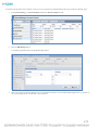
Reports ............................................................................................................................................................................................................................... 135
Manage Reports ......................................................................................................................................................................................135
Creating Report Template Definitions ...............................................................................................................................................136
Configuring Report Template Definitions .........................................................................................................................................138
Running and Viewing Reports .............................................................................................................................................................144
Exporting Reports ..................................................................................................................................................................................144
Deleting Reports .....................................................................................................................................................................................145
Graphs ............................................................................................................................................................................................................................... 146
Manage Graphs .......................................................................................................................................................................................146
4
Creating Graph Template Definitions ................................................................................................................................................147
Configuring Graph Template Definitions ..........................................................................................................................................148
Running Graphs ......................................................................................................................................................................................153
Viewing Graphs ......................................................................................................................................................................................154
Deleting Graphs ......................................................................................................................................................................................154
Using Actions with Reports and Graphs ..................................................................................................................................................................... 155
Configuring Email Actions for Reports and Graphs .......................................................................................................................155
Configuring FTP Actions for Reports and Graphs ..........................................................................................................................156
Configuring HTTP Post Actions for Reports and Graphs .............................................................................................................157
Maps ............................................................................................................................................................................................. 158
Overview of Maps ..................................................................................................................................................................................158
Creating Maps..........................................................................................................................................................................................158
Creating and Using Map Hot Spots ....................................................................................................................................................160
Map Views................................................................................................................................................................................................163
Dashboards................................................................................................................................................................................... 165
Overview of Dashboards ......................................................................................................................................................................165
Creating a Basic Dashboard ..................................................................................................................................................................167
User Accounts and Security within Asset Manager ...................................................................................................................... 172
User Accounts, Roles, and Permissions ....................................................................................................................................................................... 172
Adding Users ...........................................................................................................................................................................................172
Overview of Groups ..............................................................................................................................................................................174
Creating Groups......................................................................................................................................................................................175
Access Control ........................................................................................................................................................................................176
Advanced Asset Security .......................................................................................................................................................................178
Asset Links ...............................................................................................................................................................................................179
User Audit Trail ......................................................................................................................................................................................183
Integrating with LDAP / Active Directory ................................................................................................................................................................ 183
LDAP Server Configuration .................................................................................................................................................................183
Adding LDAP Users and Groups .......................................................................................................................................................186
Statistical Computation Engine ................................................................................................................................................... 189
Licensing ............................................................................................................................................................................................................................ 189
Adaptive Thresholds ....................................................................................................................................................................................................... 191
Integrating with RF Code IR Locators ........................................................................................................................................ 193
Integrating with PDUs and CDUs ............................................................................................................................................... 194
Using RF Code Sensor Tags with PDUs and CDUs ................................................................................................................................................ 194
Installing PDU/CDU Sensor Tags ............................................................................................................................................................................... 194
Adding PDU/CDU Sensor Tag Assets ....................................................................................................................................................................... 194
Creating a Custom PDU View ...................................................................................................................................................................................... 197
Integrating with ServerTech’s Sentry Power Manager (SPM) ...................................................................................................... 199
5
Integrating with JMX, BACnet, Modbus, and NetBotz ............................................................................................................... 201
Integrating with JMX ...................................................................................................................................................................................................... 201
JMX Monitor ...........................................................................................................................................................................................202
JMX Domains .........................................................................................................................................................................................202
Integrating with BACnet ................................................................................................................................................................................................ 204
BACnet Slave Server ..............................................................................................................................................................................205
BACnet Slave Object IDs .....................................................................................................................................................................206
Integrating with Modbus ................................................................................................................................................................................................ 207
Modbus Slave Server ..............................................................................................................................................................................207
Modbus Slave Devices ...........................................................................................................................................................................209
Modbus Slave Addresses .......................................................................................................................................................................211
Integrating with NetBotz................................................................................................................................................................................................ 213
Troubleshooting ........................................................................................................................................................................... 216
Standard Approach to Troubleshooting ...................................................................................................................................................................... 216
Troubleshooting Resources ........................................................................................................................................................................................... 216
RF Code Support Knowledge Base .....................................................................................................................................................216
Log Files ...................................................................................................................................................................................................216
Appendix ...................................................................................................................................................................................... 219
Admin Console and User Console Task Overview ................................................................................................................................................... 219
Displaying Values in the English or Metric System ................................................................................................................................................... 224
Reader Configuration with the Reader Configuration Utility .................................................................................................................................. 224
Reader Configuration with the Reader Web Console ............................................................................................................................................... 225
RF Code Tag Group Codes, IDs, and Treatment Codes ......................................................................................................................................... 228
Advanced Reader Configuration ................................................................................................................................................................................... 229
Default Asset Schemas.................................................................................................................................................................................................... 234
User Role Matrix .............................................................................................................................................................................................................. 243
Using Macros .................................................................................................................................................................................................................... 243
Macros for Reports and Graphs ..........................................................................................................................................................244
Macros for Events and Alerts...............................................................................................................................................................244
Calculations and Functions Matrix ............................................................................................................................................................................... 247
Network Security with RF Code Readers and Asset Manager ................................................................................................................................ 249
Blocking HTTP Access in Asset Manager .........................................................................................................................................249
Preliminary Steps for Using SSL Certificates with RF Code Readers ...........................................................................................249
Configuring SSL for RF Code Readers using the Reader Web Console ......................................................................................250
Configuring Asset Manager to Accept SSL Configurations ............................................................................................................251
Encryption with Key Pairs ....................................................................................................................................................................252
SNMP V1 and V3 Trap Formatting ....................................................................................................................................................252
Exporting and Importing ............................................................................................................................................................................................... 253
The Asset Manager Data Model ................................................................................................................................................................................... 258
6
Allocating Memory to Asset Manager .......................................................................................................................................................................... 262
Backing Up and Restoring the Asset Manager Database ......................................................................................................................................... 262
Backup and Restore with SQL Server.................................................................................................................................................262
Backup and Restore with PostgreSQL................................................................................................................................................263
Upgrading Asset Manager .............................................................................................................................................................................................. 264
Migrating the Asset Manager Server Application ...................................................................................................................................................... 264
RF Code Support and Professional Services .............................................................................................................................................................. 265
7
Trademarks
RF Code™ and the RF Code logo are trademarks of RF Code, Inc. Microsoft®, Windows, Windows Server, SQL Server, and Internet
Explorer are trademarks of the Microsoft Corporation in the United States and other countries. PostgreSQL™ is a registered trademark of
the PostgreSQL Global Development Group. Intel Core Duo Processor ™ is a trademark of Intel Corporation in the U.S. and/or other
countries. Firefox® is a registered trademark of the Mozilla Foundation. Safari® is a trademark of Apple Inc., registered in the U.S. and
other countries. Oracle™, Java™, and Java Management Extensions™ are registered trademarks of Oracle and/or its affiliates. BACnet®
is a registered trademark of ASHRAE. Modbus™ is a trademark of the Modbus Organization, Inc. Eclipse™ and BIRT™ are trademarks
of the Eclipse Foundation, Inc. NetBotz™ is a Registered Trademark of American Power Conversion Corporation. All other product
names are copyright and registered trademarks or trade names of their respective owners.
Copyright Statement
Copyright © 2008-2015 RF Code, Inc. All Rights Reserved.
This document, as well as the hardware and firmware described therein, are furnished under license and may only be used or copied in
accordance with the terms of such license. The information in these pages are furnished for informational use only, are subject to change
without notice, and should not be construed as a commitment by RF Code, Inc. RF Code assumes no responsibility or liability for any
errors or inaccuracies that may appear in these pages.
RF Code reserves the right to make changes without further notice to any products herein. RF Code makes no warranty, representation or
guarantee regarding the suitability of its products for any particular purpose, nor does RF Code assume any liability arising out of the
application or use of any product, and specifically disclaims any and all liability, including without limitation consequential or incidental
damages.
The user of this system is cautioned that any changes or modifications to this system, not expressly approved by RF Code, Inc., could void
the warranty. Every effort has been made to supply complete and accurate information. However, RF Code assumes no responsibility for
its use, or for any infringements of patents or other rights of third parties, which would result.
RF Code, Inc.
9229 Waterford Centre Blvd.
Building 500
Austin, TX 78758
www.rfcode.com
8
Overview
Asset Manager is an enterprise class software application. It is a highly scalable asset tracking and asset management software solution that
is tightly integrated with RF Code’s Real-Time Locating System (RTLS) readers and asset tags. It is also an advanced environmental
monitoring software solution that is tightly integrated with RF Code’s line of wire-free environmental sensors.
Asset Manager combines powerful, yet easy-to-use tools for configuring locations and asset hierarchies, creating comprehensive views of
how critical assets are deployed across departments, buildings, or entire organizations. All current and historical Asset Attributes, such as
financial information, physical location, and contractual information can be maintained in a database, enabling complete asset life cycle
management. Inventory reports are available at the touch of a button so users can proactively respond to audits and automate their
regulatory compliance efforts.
When deployed with RF Code’s active RFID tags and readers, physical asset location is tracked in real-time to quickly locate and identify
equipment for maintenance and service, avoiding costly downtime. Automated alerts and reports can be configured for immediate
notification of asset location or condition changes, delivering savings in both cost and time.
Asset Manager’s secure browser-based enterprise web console requires no software to be installed or maintained on user systems, and rolebased user accounts make it easy for system administrators to control who can view and who can modify asset details and conditions
within the deployment environment.
RF Code Asset Manager, combined with RF Code’s active RFID hardware, provides an end-to-end solution for real-time asset tracking
and environmental monitoring. In addition, Asset Manager can greatly enhance existing DCIM systems.
The major components of the Asset Manager system are the following:
•
•
•
•
•
•
Active RFID tags
RFID tag readers
The Asset Manager server
The Asset Manager web console
Optionally, infrared (IR) locators
Optionally, multiple separate instances of Zone Manager
The following sections are provided to give you a deeper understanding about RFID technology and use in general as well as technical and
operational details about RF Code hardware. If you want to begin using the RF Code Asset Manager system, you can skip these sections
and jump to the Licensing section, which is immediately followed by installation instructions for Asset Manager.
RFID Technology
Radio frequency identification (RFID) technology uses radio waves to identify objects. A radio transmitter (called a tag) is attached to the
object to be identified. A radio receiver (called a reader) decodes and reports the tag transmissions within its coverage zone. The reader
forwards this information over wired or wireless networks.
Each RF Code tag has its own on-board power supply, a CR2032 coin cell battery. Tags operate with a very low duty cycle; every 10
seconds, the tag wakes up and broadcasts a very short status message at 433 MHz before it sleeps again. The tags are one-way transmitters.
RF Code readers are dual-channel receivers tuned to receive signals at 433 MHz. They do not use high-powered radio or magnetic fields to
energize or trigger the tags in any way.
Typical RFID applications include item tracking, inventory control, asset management and environmental monitoring. A specific example
is the tracking of servers and network equipment in the data center. The impact of RFID on IT systems depends on three factors: the
power of the transmission, the distance from the emission source, and the type of equipment in the path of the transmission.
RF Regulatory Compliance and RF Transmissions Safety
Transmission power is strictly regulated by governments to ensure that IT devices can coexist with RFID systems. Part 1 of the US FCC
Part 15 mandates that a certified wireless device may not cause harmful interference. Moreover, most IT equipment is enclosed in a metal
casing that is RF-opaque to UHF transmissions at 433 MHz. RF Code tag transmissions do not penetrate the metal casings of typical IT
equipment.
RF Code systems do not have any negative affect on IT equipment in a data center or in similar environments like telecommunications
9
centers. Over two million RF Code tags have been deployed in the past decade, with more than 500,000 tags mounted directly on IT
servers. There has never been a report of data loss or degradation in any storage or security device due to the presence and/or operation of
RF Code tags and readers.
Comparison of Active RFID Tag and Cell Phone Signals
From the IBM white paper: Using RFID Technology within close proximity of IT systems and equipment (2006).
“Some cellular telephones typically operate in the same frequency range for UHF RFID and with an emission power of about 200-600
milliwatts and more… Cell phones are commonly used near, beside, or even within (3G/GPRS cards) IT equipment… Thus far, no
harmful RF interference from these uses has been reported.”
The maximum radiated emission from an RF tag operating at 433 MHz is less than 0.0028 milliwatts.
To put RF Code tag power emissions in perspective, consider that cellular telephones operate with emission power levels that are 70,000 to
210,000 times greater than those emitted by RFC active RFID tags. {200 mW ÷ 0.0028 mW = 71,429}
10
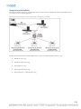
RF Code Software and Hardware Overview
Asset Manager provides a comprehensive asset management and environmental monitoring system that provides a front-end user interface
to configure and monitor RF Code active RFID tag and reader solutions, which are deployed across a wide variety of business
infrastructures. The end-to-end system builds up from the hardware layer of tags, which send message beacons to RFID readers, which
relay the information to Zone Manager, the RF Code middleware application, which then passes the information on to the top-level server,
which is then accessed by end-users through a web console launched in a standard web browser.
While potentially complex, the basic system is easy to use and maintain after the hardware has been deployed and Asset Manager has been
initially configured.
RF Code Readers
RFC readers do not use high-powered radio or magnetic fields to energize or trigger the RFID tags. RFC readers are passive, incidental
emitters with dual-channel radio receivers that are tuned to receive signals at 433.92 MHz. A digital signal processor is used to monitor the
radio messages received from the tags.
RF Code Active RFID Tags
RFC systems operate at 433.92 MHz; the tags are one-way, transmit-only communicators. RFC holds numerous FCC grants for
transmitters (tags). RFC’s patented communication protocols were designed to provide reasonable protection against harmful interference.
Tags typically broadcast their status every 10 seconds, but because each message is so short, each tag has an actual transmission time of less
than 10 seconds per day.
Tags operate with a very low duty cycle and long battery life (typically 5 years with a 10-second beacon rate).
To conserve battery power, tags remain in sleep mode 99.99% of the time; every 10 seconds, the tag will wake-up and broadcast
an extremely short status message before going back to sleep.
11
Each tags’ RF message includes its unique ID number and a short status indication (e.g., normal, location, sensor status and/or
low battery condition).
The RF message is a sequence of up to 40 short pulses, where each pulse lasts only ~27 micro-seconds. Over a 24- hour period, a
10-second beacon tag will broadcast its status message 8,640 times.
8,640 messages equals approximately 346,000 individual pulses per day. Therefore, total transmission “on” time equals: 27 microseconds x 346,000 = 9.34 seconds per day.
Prerequisite Reader Configuration
In order to use Asset Manager, you will need to have at least one RF Code reader configured and one or more RF Code Active RFID tags
within range of the reader. To configure a reader using the Reader Configuration Utility (RCU), refer to the Reader Configuration with the
Reader Configuration Utility section in the Appendix. Additionally, you can test reader reception of tag beacons using the reader web
console; this process is described in the Reader Configuration with Reader Web Console section in the Appendix. Later, after installing
Asset Manager, you will add one or more readers and one or more Tag Group Codes within Asset Manager.
12
RF Code Zone Manager
Zone Manager is a real-time location engine designed specifically for use with RF Code’s asset tracking and wire-free environmental
monitoring solutions. Zone Manager handles all of the direct hardware interfaces for RF Code readers and tags. Zone Manager is
essentially the engine under the hood of Asset Manager and was designed for easy integration with one or more business applications via its
open application programming interface (API).
Integration with the RF Code middleware / location engine known as Zone Manager involves utilizing the communications interfaces
defined in the “Zone Manager API Specification” (http://support.rfcode.com/customer/portal/articles/716011) document.
The Zone Manager interface is extremely flexible and powerful. It can be utilized in almost any development environment due to the
following characteristics of the Zone Manager API Specification:
Telnet or web API based communications
Platform (operating system and hardware) independent
Programming language independent
The Zone Manager software provides a great deal of value and functionality that can be easily leveraged such as:
Reader communications channel management (for up to thousands of readers)
Reader initialization, modes, and configuration
Data buffering, filtering and interpretation
Reduction of duplicate data from multiple readers
The Zone Manager middleware / location engine is not an end-user application, but was designed instead to be used in conjunction with
an end-user application that can benefit from consuming the data and information produced by the Zone Manager system. It is important
to note that the Zone Manager system is not designed to be a database of historical values or provide tag to asset association. Zone
Manager is designed to collect and track (in real-time) the last known (latest) information about tag location, status and sensor readings.
13
Since Zone Manager does not log historical data in a database, it is extremely scalable with the ability to service thousands of RF Code
readers while operating on a single dual core server system. However, Asset Manager stores data in a database and enables historical
records of reader, tag, and asset data.
The Zone Manager middleware/location engine allows for communication via a web or URL style API as well as a telnet style TCP/IP
connection. The communications can be interactive (command / response) as well as registration or subscription based to follow updates
or changes. The Zone Manager specification provides an extensive list of commands to fully control the RF Code readers and Zone
Manager such as:
Defining tag groups (which tags to listen for)
Adding readers to the system as well as defining reader configuration parameters
Location and rule configuration
Tag and reader online/offline notifications
Query capabilities such as which tags are in a specific location
Multiple data output formats such as JSON, CSV, and XML
Integration with RF Code’s Zone Manager does not require RFID specific or RF Code hardware skills. It does require a fair amount of
standard software programming skills to configure programmatically the system and utilize the data returned by the system. Ideally
integration with Zone Manager would tie the system into an existing asset management or monitoring solution. RF Code highly
recommends attending a training class to learn the details of the RF Code Zone Manager system. Contact RF Code support for
information on training classes.
Zone Manager is bundled with Asset Manager and accommodates a single Zone for reader and tag environment coverage. However, Zone
Manager can be installed on one or more separate servers. The system requirements for Zone Manager installations when installed apart
from the Asset Manager installation are less stringent, as the Zone Manager application requires a smaller footprint and less computing
resources to function. For alternate or expanded configurations, please refer to the Zone Manager User Guide and consult with RF Code
Support for optimal deployment conditions and configuration.
Licensing Overview
Asset Licenses
Asset Manager is licensed based on the number of assets configured in the system. The types of assets defined are irrelevant as any asset
counts and consumes a license. An asset can be an inventory type asset (with or without an asset tag associated with it), a sensor asset
(sensor tag), or a summary asset. Note that an asset is not the same as a tag. An asset can be created without a tag associated to it and this
will still consume a license. All the assets defined in the system consume licenses; however, no other configured object in the system
consumes a license.
For example none of the following items consume licenses:
Readers
Zone Managers (local or remote)
Users, Managers, or Administrators
Locations or Rules
Tag Groups or Unassigned tags
Maps
Dashboards
For Asset Manager, the licensing mechanism is based purely on the number of Assets defined in the system. Any asset added to the system
will consume a license regardless of the schema configuration. Again, this means that every Inventory, Sensor and Summary Asset will each
consume a license. The licensing facility works independent of the schema definitions of asset categories; all “Assets” are of equal value and
count equally as a licensed entity. The number of Locations, Users, Readers, etc. defined in the system has no bearing on the licensing.
14
Assume an Asset Manager system contains all of the following:
50 readers
10 users
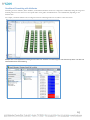
60 IT Racks spread across 6 rows in a single data center
75 unique locations defined in the Location Tree
2,500 inventory assets
350 sensors assets
67 summary assets (associated to the 60 IT Racks, 6 Rows, 1 Data Center locations)
Licenses are consumed only by the assets in the last three bullets: the 2,500 inventory assets, the 350 sensor assets, and the 67 summary
assets. However, none of the readers, users, racks, or locations in the Location Tree consume a license; therefore, the total number of
licenses required in this scenario would be 2,917.
Most often an asset does have an asset tag or sensor tag associated with it, but this not always the case, especially with summary assets.
Summary assets are assets that represent a location and an asset. Summary assets typically don't have asset tags associated to them, but like
all other assets, they each consume a license. For more about summary assets, refer to the Summary Asset section.
Knowing how licenses are consumed is important when you calculate the number of licenses that you need to purchase.
Licenses for Advanced Features and Modules
Additional or premium features are also licensed and can be unlocked or enabled by entering the appropriate license key. The following
premium features are license controlled:
JMX and Tivoli Monitoring Integration
BACnet Integration Module
Modbus Integration Module
ServerTech Sentry Power Manager (SPM) Integration
Statistical Engine and Adaptive Thresholds
These premium features are licensed once and are then available regardless of the number of assets defined in the system.
NOTE: If you need more licenses, please contact your RF Code Sales representative.
15
Installing Asset Manager
In order to install Asset Manager, you must ensure that the application server (and the database server, if you are installing these
components on different servers) meets minimum system requirements.
System Requirements
For production environments, adhere to the following system requirements when preparing your hardware, operating system, and database
for Asset Manager:
Operating Systems Supported
64-bit Windows 7
64-bit Windows 2008 Server
64-bit Windows 2012 Server
64-bit Red Hat Enterprise Linux (RHEL) 5.5 – 6.4
64-bit CentOS Linux 5.5 – 6.6
64-bit Oracle Linux 5.5 – 6.5
Databases Supported
PostgreSQL version 8.3 (Preferred Version = 9)
Microsoft SQL Server 2008 and SQL Server 2012
IBM DB2 v9.7
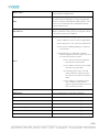
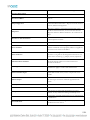
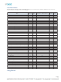
Hardware Requirements Table
The following table provides the minimum hardware specifications required to run Asset Manager depending on the number of tags you
will deploy in your production environment.
Number of Tags in
Deployment Environment
CPU Cores in the
Application Server
RAM installed in the
Application Server
< 1,000
2
2GB
< 10,000
2
3GB
< 20,000
4
4GB
< 30,000
4
5GB
NOTE: The storage space required to host your data can be calculated with the assistance of the RF Code Storage Capacity Calculator.
For more information, refer to the RF Code Storage Space Calculator available online:
http://support.rfcode.com/customer/portal/articles/760679 .
Web Browsers Supported (Client Support)
Microsoft Internet Explorer 10 & 11 (IE 10 & IE 11)
Mozilla Firefox 36
Google Chrome 41
Apple Safari 8
Installation Instructions
Windows Installation Instructions
To install Asset Manager in Windows, perform the following steps:
1.
Run the installer’s executable file from the RF Code Asset Manager CD or from the Asset Manager file that you downloaded.
16
NOTE: RF Code Support can provide entitled customers with download links to the Asset Manager installer and upgrade
executable files.
2.
When the Asset Manager Setup Wizard starts, click Next to continue.
3.
Read the License Agreement, dot the radio button next to I accept the agreement, and then click Next.
4.
Accept the default location for the installation folders and files or choose an alternate path that you would prefer.
NOTE: If you choose an installation path other than the default, be sure to note this information and keep it accessible should
you ever need to contact RF Code Support.
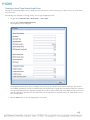
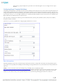
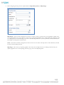
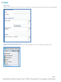
5.
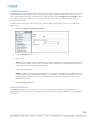
Click Next and in the Select Components window, use the drop-down menu and choose the installation option you prefer.
NOTE: Most often you will want to choose the first option in the drop-down menu that installs both Asset Manager and Zone
Manager, as opposed to installing only the Zone Manager component; the latter is only done if you already have an existing
installation of Asset Manager on another server.
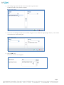
6.
On the next window, click Install.
7.
Click OK to install the default database, Microsoft SQL Server Express Edition, which is bundled with the Asset Manager
installation package.
NOTE: Choose this option only if you are installing AM as a pilot installation. SQL Server Express is not supported as a full
production database for reasons such as scalability, configuration options, and performance. If you do choose to install the
bundled version of SQL Server Express to use as a database initially, be prepared to use it only as a temporary store of data and as
a proof of concept. You will want to start from scratch when you install Asset Manager with a fully functional database when you
deploy to a production environment.
NOTE: During the installation of SQL Server Express, do not change the default Administrator (sa) password. Doing so will
prevent AM from being able to connect to the database for initial setup and initialization.
8.
Accept the Microsoft SQL Server Express license agreement and then click next.
9.
Accept the default installation directories.
10. Accept the default Named Instance, Instance ID, and Instance root directory, and then click Next.
11. Accept the default database engine settings and then click Next.
12. Configure the error reporting settings and then click Next.
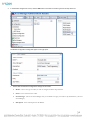
13. Specify the service accounts.
17
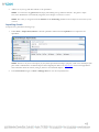
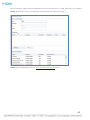
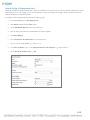
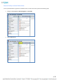
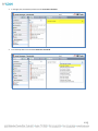
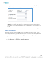
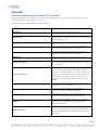
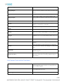
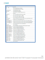
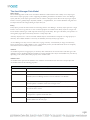
Ports Used by Asset Manager
The following table lists the ports that are used by Asset Manager by default; however, you can change these later if necessary within the
Asset Manager web console.
PORT
Use/Application
80
SPM integration
6580
HTTP Interface
6581
HTTPS Interface
6503
Reader Up Connect Port
6502
Zone Manager Updates Port
502
Modbus Slave Port (if enabled)
8686
JMX Monitor Port (if enabled)
47808
BACnet Slave Port (if enabled)
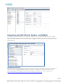
Installing with Microsoft SQL Server Professional
Asset Manager stores all data about assets, locations, history, and users in a database that is external to the server software.
NOTE: As of Asset Manager v2.8, Microsoft SQL Server 2008 and SQL Server 2012, as well as PostgreSQL 8.3 and DB2, are supported
databases. Microsoft SQL Express 2008 is provided as a part of the Asset Manager installation package and installation wizard;
however, it is intended for use in labs and for limited pilots. The Express version of SQL server is limited to 10GB of database
size, and does not have the capability of performing scheduled backups. Also a Microsoft Management Console is not installed as
part of the Asset Manager install.
When deploying in a production environment, use Microsoft SQL Server Standard (not Express), PostgreSQL, or DB2 so that you can
perform essential database maintenance functions, such as backing up, restoring, re-indexing, and administering the data generated by Asset
Manager.
To configure either PostgreSQL or SQL Server for production use with Asset Manager, a database must be created that is not populated
with data and a user that has access to the new database must be created and given full access to the database. Do not use the “root” or
“sa” accounts for security reasons. The database can be run on the same system that Asset Manager is installed on or it can be run and
accessed by Asset Manager on a remote machine. While knowledge of SQL statements and database schema are not required to administer
Asset Manager, administrators must know how to create, secure, backup, restore and re-index the database software they choose to use.
Beyond the basic tasks related to database configuration, there are a few other tasks that require a combination of database configuration
and software settings. The first task is the initial connection of the Asset Manager software to the database (unless SQL Server Express
2008 was installed as part of the Asset Manager installation. If it was installed then a database is already created and configured for Asset
Manager, but can still be changed or managed by following these directions). The following steps must be taken for initially connecting
Asset Manager to a new production database.
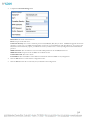
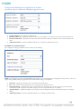
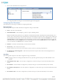
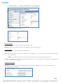
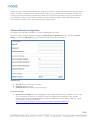
Configuring a Production Database
You can configure a production database following one of the two methods described below, depending on your needs.
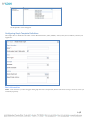
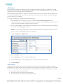
Method A
This method applies when using an SQL Server or PostgreSQL with Mixed Mode Authentication turned on.
18
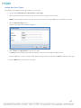
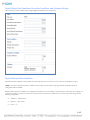
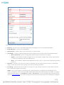
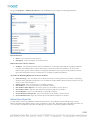
1.
In your Database Management Application, create a New Database and create or authorize a User with full access to the new
database.
2.
Install Asset Manager.
NOTE: Do not check the “Install SQL Express” checkbox.
3.
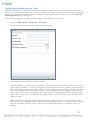
Click the Asset Manager icon after the installation is complete and then login as admin/admin.
4.
Select the database type.
5.
Enter the correct hostname, database name, user ID and password.
6.
Click Test.
7.
Click OK.
NOTE: The Asset Manager service will restart and after 3-5 minutes the database will be populated with the minimal amount of
data and the Asset Manager system will be up and running.
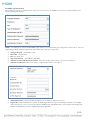
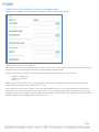
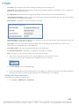
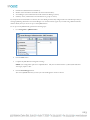
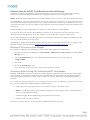
Method B
This method uses SQL Service Windows Authentication.
1.
In your Database Management Application, create a New Database in SQL server and from the DOMAIN accounts, select a user
and grant that user access to the new database.
2.
On a computer that is a member of the domain, install Asset Manager.
NOTE: Do not check the “Install SQL Express” checkbox.
3.
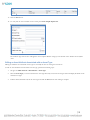
After Asset Manager is installed, shut down the Asset Manager service.
4.
Then, under the “Log On” tab, change the “Log on as” entry from “Local System Account” to “This account” and select the
domain user that was granted full rights on the new database.
5.
Enter the user’s password and click OK.
The user will be granted log on as a service rights.
6.
Start the service and login as admin/admin.
7.
Enter the database type and hostname of the database server and check the Use Windows Authentication checkbox.
NOTE: Do not enter a username or password.
8.
Test the connection and make sure that it passes.
9.
Click OK.
The software will reboot and after 3-5 minutes, the database will be populated and the software will be back online. To check
this, go to the Asset Manager web console page and log in.
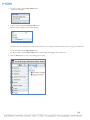
19
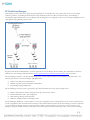
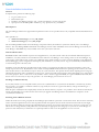
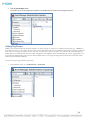
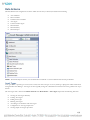
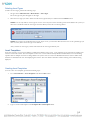
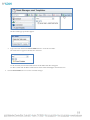
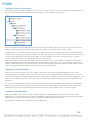
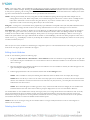
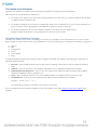
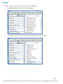
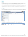
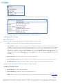
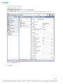
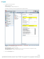
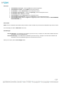
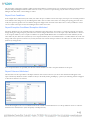
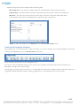
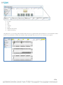
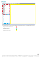
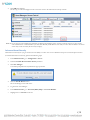
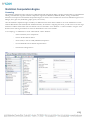
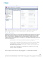
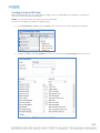
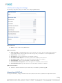
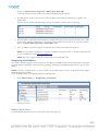
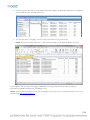
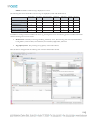
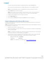
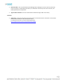
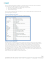
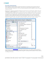
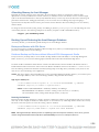
AM Directory Structure and Files Present after Windows Installation
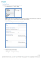
After installing Asset Manager, the directory structure in Windows will look like the following:
The folders of particular interest are the following:
•
•
•
conf – contains the system.properties file
jetty – contains log files that are often useful for troubleshooting
zonemgr.datadir – contains the Zone Manager database and files when it is installed with Asset Manager
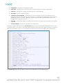
The System Properties File
The system.properties file contains configuration directives for the software that may not be set inside the database or may be needed in
order to connect to the database when the service is started. Changes made to this file are preserved when Asset Manager is upgraded. The
file is modified whenever database connection parameters are changed within the Asset Manager software. Additionally, directives can be
modified and added by hand that will change the behavior of the software.
NOTE: Do not edit the system.properties file without first contacting RF Code Support.
It may be beneficial to have this file included in the regular backup regimen of the system. All other unique information for Asset Manager
other than what is contained in this file is stored in the database. As a result, if the system where Asset Manager resides is lost, the database
backup is all that is needed to restore the system.
NOTE: It is very important that database backups are performed on a regular basis. For more information about backing up and restoring
the database, refer to the Backup and Restore section in the Appendix.
20
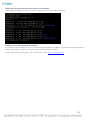
Linux Installation Instructions
Overview
In simplest terms, perform the following steps:
1.
2.
3.
4.
Log in to Linux as root.
Download the rpm
Install the Asset Manager package: rpm –i rfcode-assetmanager-{version}.x86_64.rpm
Open ports in the firewall: iptables –I INPUT –p tcp --dport {Port #} –j ACCEPT
Files Required
The Asset Manager install for the supported Linux platforms consists of two rpm files that are only compatible with 64-bit distributions of
Linux.
These rpm files are:
rfcode-am-zonemanager-{version}.x86_64.rpm
rfcode-assetmanager-{version}.x86_64.rpm
The Zone Manager RPM contains the Zone Manager component and may be installed on systems that will only run a Zone Manager
instance. The Asset Manager RPM will install the Asset Manager software and an embedded version of Zone Manager reserved only for
Asset Manager. Both RPMs may not be installed on the same system at the same time.
Linux Installation Notes
Both RPM installers will install their respective rfcode applications in /usr/share/rfcode. RF Code recommends 5GB of disk space be
available for /usr/share/rfcode for most installations unless either the Zone Manager “event caching” feature or the Zone Manager “tag
event logging” feature will be used. In these cases, additional storage will be needed on a case by case basis depending on the application
desired. All logging, system configuration and temporary files will reside in /usr/share/rfcode. Logs are automatically rotated and there is
no unbounded growth of the file system.
Installation of the Zone Manager rpm will install one file outside of /usr/share/rfcode called /etc/init.d/rfcassetmanager. This is the
startup script for the service. By default the service will be started upon RPM install and when the operating system is at init 3, init 4 and
init 5 and also features a clean shutdown script on init 0, init 1, init 6 and init 2. The rpm file will also add an unprivileged user and group
called rfcode that will be used as credentials to run the service. This account will not be interactive and its shell will be set to /sbin/nologin
for security purposes. Root or sudo access is only needed in order to install or upgrade the RPM, as is typical of RPM-based installs; this
level of access is not necessary for day to day operation. No Asset Manager process will ever run as root.
Installing in a different directory
If /usr/share/rfcode is not an acceptable location, then create a symbolic link for /usr/share/rfcode that links to the directory (location)
that you prefer. For example, to install the software in /opt/rfcode, first create the /opt/rfcode directory and type the following: ln –s
/opt/rfcode /usr/share/rfcode
When the rpm is installed, the files will physically reside at the alternate location you prefer. It is possible to move the files and modify the
startup script manually, but you will encounter issues when you upgrade Asset Manager because the installation is scripted to use the
/usr/share/rfcode directory.
Executing under a Different Account
Neither the rfcode user nor the group that the Zone Manager rpm installs has a password or an interactive shell. The account is exclusively
used to execute the application at a lower level of permission than the superuser account. If the execution account needs to be changed,
this can be done by editing the startup script and modifying the execution user to be the preferred account. However, if you do this, you
will also have to change the file system permissions to be owned by the appropriate user and group. If you must run Asset Manager on
ports lower than 1024, then you will need to use a special procedure in order to run the application as a non-root user.
21
Executing the install
In order to install the software, use the rpm –i command and then supply the file name for the rpm to be installed. The install must be
executed at a root privilege level either by being root or by using sudo.
rpm –i rfcode-am-zonemanager-{version}.x86_64.rpm
OR
rpm –i rfcode-assetmanager-{version}.x86_64.rpm
Service Notes
Once the service has been installed, it is managed through common operating system tools. When the system restarts there is no need to
interactively start or stop the service manually. If however, starting or stopping the service is desired the following commands are useful.
service stop rfcassetmanager
service start rfcassetmanager
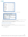
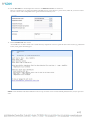
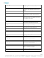
Configuring Linux Firewall Settings
The following ports will need to be allowed through the firewall if their use is desired. The installer will not create these exceptions so if the
operating system firewall is turned on this will need to be manually accomplished.
Port Number
6580
6581
6503
6502
Description
HTTP interface
HTTPS interface
Reader Up Connect Port
ZM Updates Channel
Notes
HTTP or HTTPS access is needed
HTTP or HTTPS access is needed
Needed when using reader up connect feature
Optional integration interface
To set up the Linux iptables firewall to allow these ports through, the following commands need to be issued with root privileges.
iptables –I INPUT –p tcp --dport 6580 –j ACCEPT
iptables –I INPUT –p tcp --dport 6581 –j ACCEPT
iptables –I INPUT –p tcp –-dport 6503 –j ACCEPT
iptables –I INPUT –p tcp –-dport 6502 –j ACCEPT
service iptables save
These commands will create the rules and save them so that they are persistent after rebooting.
22
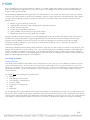
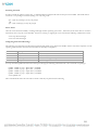
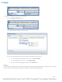
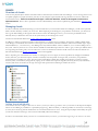
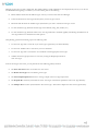
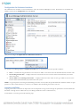
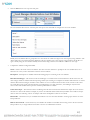
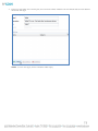
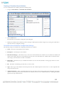
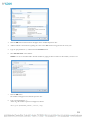
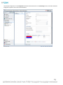
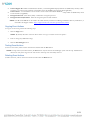
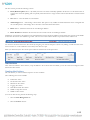
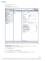
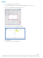
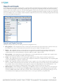
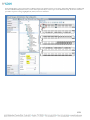
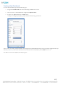
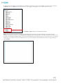
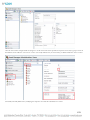
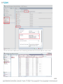
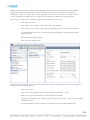
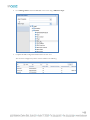
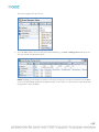
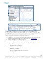
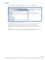
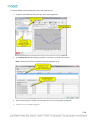
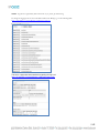
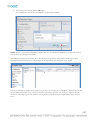
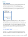
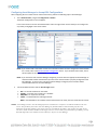
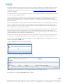
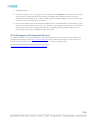
AM Directory Structure and Files Present after Linux Installation
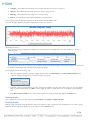
After installing Asset Manager in a Linux environment, the directory structure will look like the following:
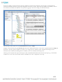
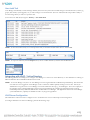
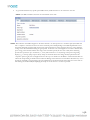
Installing in Linux with a PostgreSQL Database
If you wish to install Asset Manager in a Linux environment using PostgreSQL for your database, you will need to install PostgreSQL and
configure Asset Manager to point to it by using the settings under Configuration > Database.
For more information about PostgreSQL, refer to the third-party website: http://www.postgresql.org.
23
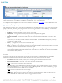
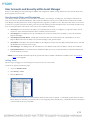
Getting Started with Asset Manager
Asset Manager is a robust enterprise application that is easy to install and use almost immediately, but it has incredible flexibility to
accommodate complex environments and enormous deployments of millions of tags and assets. However, as with any system that can be
both simple and complicated to manage, Asset Manager requires a fundamental understanding of its structure and the possibilities therein,
as well as knowledge of the quickest paths to determine what direction is right for your particular needs.
With any asset management system, the fundamental structure involves assets (objects or conditions of interest), the location of those
assets, and the state of those assets. This summary encompasses the need to keep data center computing equipment functioning optimally,
expensive hospital equipment tracked and available for easiest use.
Typically, a system administrator installs and configures the application and database for a population of end users. Asset Manager is no
different. This guide is written for an audience of administrators, as they need to know everything, and then some, about the application
they are deploying and/or supporting. Within this guide are also the means by which end-users can access the information they need to
ensure that their assets are functioning and functioning optimally.
Keep in mind that there are assets in the system and that these assets have attributes (characteristics with values). This distillation of objects
and relationships accounts for physical objects that are managed through physical structures as well as the physical conditions of the
environments in which the physical objects exist. Asset Manager provides a dynamic map of the territory for which you are responsible.
This map will tell you where your assets are, how they are doing, and if they move, then you’ll know that they did and you’ll know where
they went if they are still in your territory. If an asset does leave your territory, then you’ll know where it was prior to departure.
Configuring and Using Asset Manager
After installing Asset Manager, the first things you need to do are basic configurations and these are clearly shown in the Dashboard under
System Status in the System Configuration window pane. The five (5) preliminary components that you need to configure are: a Database,
a Zone Manager, a Reader, Tag Groups, and a basic License Key.
The Asset Manager Database and a local Zone Manager will already be configured if you chose the local Zone Manager option and the
SQL Server Express options during the installation process and you will know they have been configured because these Components will
appear with green check marks next to them in the Configured column.
The following sections will explain how to add a License and how to configure one or more Readers and Tag Groups. Until you configure
each of the five basic System Configuration components, there will be a red X next to each. The red X will change to a green checkmark
after you complete the initial configuration for that component.
The instructions for configuring these primary system components are found in the sections that immediately follow this one; however,
this section provides an overview of the Asset Manager web console in order to help you understand the structure of the web console
application and to help you navigate within it.
24
Asset Manager Web Console Overview
The Asset Manager web console contains a navigation menu on the left with links and sub-links, or Tasks and Sub-Tasks that you click in
order to populate one or more panes of information on the right side. These panes will either simply display information about various
parts of the Asset Manager system or they will contain additional fields or functions that you can configure.
There are two primary views (consoles) in Asset Manager:
Admin Console: Access this console by clicking the “Admin Console” link in the lower right corner of the web console of Asset
Manager. This console is typically used for administrative functions of the server and where a large portion of this document
focuses. It could be considered the “Control Panel” of your Asset Manager. This is where most of the initial configuration is
done.
User Console: Access this console by clicking the “User Console” link in the lower right corner of the web interface. This
console is for managing and viewing sensors, alerts, dashboards, reports, graphs, etc. This is where the final configuration and
daily use of Asset Manager is done.
NOTE: Switching between the Admin Console and the User Console is done by clicking either the Admin Console or the User
Console link at the bottom right of the user interface. The name of the link changes depending on which console you are using and
will always display the name of the console that you are not currently using.
25
Bookmarks
At the top left of the web console is the Bookmarks Menu, the Add Bookmark button (immediately to the right of the Bookmarks Menu),
and the Configure Bookmarks button (immediately to the right of the Add Bookmark button).
The Bookmarks Menu is simply a drop-down menu that lets you go quickly to any Bookmark you have added and configured.
The Add Bookmark button lets you add a new Bookmark of your current page location and view to the Bookmarks Menu.
To add a new Bookmark, perform the following steps:
1.
Click the Add Bookmarks button.
2.
Give the Bookmark a Name and then click OK.
The new Bookmark appears as a choice in the Bookmarks Menu.
26
To configure your Bookmarks, perform the following steps:
1.
Click the Configure bookmarks button.
The Bookmarks Menu configuration window appears.
Next to the column header for Name is the Bookmark configuration drop-down menu.
To sort your Bookmarks alphabetically from A to Z, click Sort Ascending.
To sort your Bookmarks from Z to A, click Sort Descending.
To remove a Bookmark, highlight it and then click the Delete button.
Folders
Another useful tool available from most of the Task configuration areas, including the Dashboard task configuration area, is the Folder.
The New Folder button is found the horizontal row of buttons to the right of the Bookmark Menu.
27
Using Folders in Asset Manager is the same as it is in most graphical operating systems and provides a way to categorize and organize your
“files,” which in the case of Asset Manager can be Reports, Graphs, Events, Alerts, Asset Templates, etc.
As a simple reference, an example of how to create and use a folder can be found in the Asset Template section of this document. Other
examples of creating folders can be found in various other sections of this document.
The Administrator Console
The Administrator Console is used to manage the system infrastructure. It is used by an administrator to set up a system structure for the
purpose of discovering, monitoring, and tracking your assets that have been tagged with RF Code Active RFID tags. The Administrator
Console provides (or enables) the following tasks:
•
•
•
•
•
•
•
•
•
Dashboard – to configure the primary views for end-users of the system
Configuration – to configure the parts of the system necessary for viewing and storing tag data
Integration – to configure optional modules that integrate with third-party hardware and software
Location/Rules/Maps – to configure the logical structure that represents your physical deployment of tags, readers, and IR
locators
Data Schema – to configure the types, assets, and sensors you will be using and the specific attributes of them that are important
to you; however, for most deployments, this should not need to be modified. Consult with RF Code Support if you think you
need to modify the default schema
Security – to configure user accounts and access levels in the system
Reports/Graphs – to configure the presentation of data that is reported from the system
Events – to configure the types, parameters, and triggers of system-generated notifications when certain conditions occur so that
administrators can manage the hardware and the software of the system
Alert Management – much like Event configuration, Alert Management is used to configure the types and parameters of
system-generated notifications when certain conditions occur so that end users can manage the state and status of assets and the
environment that is being monitored
The Administrator Console is divided into two main regions, or panes. The left side is the navigation pane where the tasks and sub-tasks
are located.
To the right of this is the task pane which contains several varying task panes depending on the main and sub-task selected. The
administrator console also contains an information bar on the bottom of the screen, which contains two main features:
•
•
User Indicator - shows the username (or admin) who is currently logged on and using the web console session.
Bottom Navigation Links - Logout, Link, About, Help, User Console (Admin Console)
Logout – Click Logout to end the current web console session.
Link – Click Link to create a URL string that can be copied and pasted to send in an email or pasted into a browser window or
browser tab. An alternate URL copy-paste option is to create a URL string that will open the active window pane, e.g., to open
the configuration settings pane for a specific asset type or attribute.
About – Click About to show the version of Asset Manager
Help – Click Help to open the administration and usage guide as a PDF file.
User Console – Click User Console to switch to the User Console from the Admin Console. In the same place in the web
console, the link will read “Admin Console” if the user is logged into the User Console.
28
The User Console
The User Console lets Users manage assets and monitor environmental conditions, whether the Asset Manager system is deployed in a
datacenter or elsewhere. The User Console provides the following tasks:
•
•
•
•
•
•
•
Dashboard
Tag Management
Customization
Maps
Reports/Graphs
Events
Alert Management
For screenshots and brief descriptions of all the Tasks and Sub-Tasks available in both the Admin Console and the User Console, refer to
the Admin Console and User Console Task Overview Matrix section in the Appendix.
Adding Licenses
To enter a license key, perform the following steps:
1.
Go to Configuration > License Keys.
All license keys are displayed in this area after they are installed.
29
2.
Click the Add License Key button.
3.
Enter the license key that your sales representative has provided to you.
4.
Click the OK button.
The license key will then appear in the list with the license key parameters of License Count, Expiration Date, and License Key
Type.
30
5.
Go back to the Dashboard > System Status area.
You will see that the Configuration status for License Key(s) has changed to display a green checkmark.
Adding and Configuring Readers
After you have configured one or more readers through the reader web console or reader configuration utility (RCU), you then need
to add your reader(s) to Asset Manager. For further details, refer to the Prerequisite Reader Configuration section found earlier in
this document.
Before you have configured any readers in Asset Manager, the Admin Console Dashboard will show a red X next to Reader(s) under
System Configuration.
Reader Configuration in Asset Manager is done in the Reader Configuration task area. There you will see two task panes. In the
center column is a tree of readers installed and configured in Asset Manager (which will be empty at first) and on the right is the task
pane where reader configuration information is entered.
To configure a reader, perform the following steps:
1.
In the Admin Console, navigate to Configuration > Readers.
31
2.
In the Readers configuration screen, click the New button and select the reader type from the drop down list.
The Reader Configuration settings will appear in the right pane.
3.
Set the Basic and Network configuration settings for the reader:
•
Reader - Choose the type of reader you wish to configure from the drop-down list.
•
Name - Create a name for the reader.
•
Zone Manager - Choose the Zone Manager that you would like to assign your reader to (by default this is your local
Zone Manager).
•
Description - Enter a description for this Reader.
32
•
Enabled - If you would like your reader to go active and receive and transmit tag data after saving your configuration,
check this box.
•
Hostname - Enter the IP address of your reader in this field.
•
Port - Enter the port number over which to communicate with your reader (by default this is 6500).
•
SSL Mode - Select OFF (to turn SSL mode off on the reader), IFAVAIL (uses SSL on the reader if available),
REQUIRED (requires use of SSL) or STRICT (will authenticate the matching hostname, if the hostname does not
match the reader will not connect).
NOTE: When getting started, you will want to accept most of the default entries. If you need to make changes in the future, refer
to the Advanced Reader Configuration section in the Appendix. For example, if you will be using multiple Zone
Managers, then you will not only have to add and configure the others later in Asset Manager, but you will also have to
select (or change) the appropriate Zone Manager to which your reader will be associated. Initially, or if you will only be
using a single Local Zone Manager, then leave the default option selected for Local Zone Manager.
NOTE: Additional reader configuration options are described in the Advanced Reader Configuration section in the Appendix.
33
4.
Click the Save Changes button.
The reader you have just configured will appear in the middle pane to the left for the configuration pane.
Adding Tag Groups
Adding a new Treatment Sub-Code, hereafter referred to as the Tag Group (e.g., 04V), lets you add new Group Codes (e.g., THSRCK) to
the system; by doing so, you are telling the system how to interpret beacons from your tag population. Group Codes need to be configured
in the system for each type of tag that you have. After this, you can then see what your readers “see,” which are all of the individual tags
sending beacons to and being received by the readers configured in Asset Manager. Then, after identifying the “active” tag population, you
can associate the individual tags with your assets and/or identify them as sensor tags and assign them to the locations where they will be
monitoring environmental conditions.
To add a new Tag Group, follow the steps below:
1.
In the Admin Console, go to Configuration > Tag Groups.
34
2.
In the right window pane, click the Tag Group drop-down menu and find the correct Treatment Code for the Tag Group that
you want to add.
NOTE: The Treatment Code is printed on each tag on the bottom right corner of the label. When you enter a Treatment Code,
the Group Code will pre-populate with a common Group Code; however, this may not match the Group Code on your tag. If it
does not, enter the Group Code on your tag instead. Refer to the sections on Tag Codes in the Appendix and/or to following RF
Code Knowledge Base article for more information about Group Codes and Treatment Codes:
http://support.rfcode.com/customer/portal/articles/723973.
After clicking the Treatment Code, the right pane will fill with Tag Group configuration fields.
In the Basic Information section, the Group Code (e.g., RFCRCK) will be pre-populated.
NOTE: Each Tag Group can have multiple Group Codes, so you may need to specify a different Group Code. For more
information, refer to the RF Code Tag Group Codes, IDs, and Treatment Codes section in the Appendix.
3.
In the Name field, type the Group Code again, unless you need to name the Tag Group something different.
4.
Click the Save Changes button at the bottom of the window.
35
Assets
Overview of Assets
Assets are the physical objects and the environment that are tracked and/or monitored with Asset Manager. Assets can range from servers
to hospital equipment to people (and others), but they can also simply be (represent) RF Code tags themselves in the case of RF Code
environmental sensors. Assets are classified as Asset Types. Assets have Attributes. Assets can be assigned to Locations and
Expected Locations. There is also a special class of Assets called Summary Assets that are explained in great detail in the Summary Asset
section.
Managing Assets
In order to efficiently and effectively manage your assets and monitor your environment within Asset Manager; you will need to plan and
define a location hierarchy in which your assets exist. Before deploying Asset Manager in your production environment, you will need to
have a good understanding of the logical Locations that are used in Asset Manager; however, you can use the pre-defined location
hierarchy when you add the first few assets to the system while you are learning how to use it.
Locations are described in detail in the Location and Location Hierarchy section.
In addition to needing a properly structured Location Hierarchy, you will also want to extend the schema that is initially available within
Asset Manager. The schema is the collection of Asset Types, Asset Attributes, Calculated Attributes, and Custom Attribute Types. Upon
initial installation (i.e., “out of the box”), Asset Manager has only a limited number of these available for you to use when adding assets to
the system. However, there are two “stock” schemas available for immediate import and use in order to give you more pre-defined choices
for categorizing and working with you assets and sensors. These two default asset schemas and all of the assets and asset attributes are
discussed in detailed in the Default Asset Schemas section in the Appendix.
Prior to importing one of the default asset schemas or creating any new Asset Types, the Asset Type Hierarchy will appear with limited
choices; therefore, you will need to import a schema or manually create the specific Asset Types that you need for your production
environment prior to adding new Assets. The base schema, immediately available after installing Asset Manager, contains no specific
Inventory assets, such as Server, Storage Device, Laptop, etc. It contains three top-level categories (Inventory, Sensor, and/or Summary –
Location) and eleven second-level or sub-type Asset Types that represent the standard types of RF Code sensors.
Adding Assets Individually
From the User Console, configure a few assets or sensors (as assets) in order to get started. Later you can then use the Export and Import
features of Asset Manager, in addition to a spreadsheet program (e.g., Microsoft Excel), to add a large number of assets and/or sensor tags
(as assets) all at once along with the attributes that are associated with all of those assets. Using the Export/Import functionality will spare
you the time and effort of having to enter each asset individually within Asset Manager.
In order to view information about your assets or to collect data from your sensors, you must first assign a tag to an Asset or as an Asset.
36
To add a new asset to Asset Manager, perform the following steps:
1.
In User Console browse to Tag Management > Manage Tags.
2.
Select the tag(s) under the Import Detected Tags column and click the Add Selected Tag(s) button, or simply click Add All
Tags.
This will move the tags to the Unassigned Tags column.
3.
In the Unassigned Tags column, right-click on the tag to be assigned in the far right column and then select New Asset.
37
4.
Select the appropriate Asset Type to assign to the tag.
NOTE: In this example, a server asset is being added; therefore, Server is chosen as the Asset Type.
NOTE: As mentioned previously, Server and the other Inventory Assets seen in the Location Hierarchy below are only available
after they have been manually created or after one of the Default Schemas has been imported.
5.
Configure at minimum the following asset fields:
Name: This is a common description of the Asset and it must be unique. One common practice for naming sensors is to
pre-pend a sensor tag type designator, e.g., TempHum (or TH) to a description of that asset’s physical and/or logical
location, e.g., AustinDataCenterRow1Rack1-Top, such that the name reflects both, e.g., TH-AustinDataCenterRow1Rack1-Top.
Asset Tag: Depending on how you navigated to this screen, this field may already be pre-populated. If is not, simply start
typing the unique ID of the tag and you will be able to select the specific Tag ID from the list that is presented to you
dynamically.
Asset Location: This field is used to tell Asset Manager where the tag will reside physically. Chose the appropriate location
of the tag from the Location Hierarchy, e.g., the specific rack where a temperature sensor asset is physically installed.
Lock Location: Check this box if the asset is not a mobile asset, e.g., an environmental sensor that should not be moved
after deploying it.
38
NOTE: The rest of the fields are optional, but when you are comfortable with Asset Manager, then you can configure them to enter and
thus monitor a great deal about your assets and your environment.
Environmental Monitoring with Sensor Tag Assets
Using RF Code sensor tags, you can monitor temperature, humidity, and other environmental conditions. When you configure Asset
Manager to use sensors, you will be adding the sensors as Assets and designating a location for each one of them. For example, you can
add a temperature sensor as an asset tied to a specific location in your data center, e.g., to Row 1 Rack 1. Additionally, with sensor tags,
you can also configure the following three (3) additional fields:
•
Temperature Sensor Application: This pull-down allows the software to designate how this sensor is deployed, e.g., IT
Cabinet/Rack.
•
Airflow Position: This field designates if the sensor is in the front or back of the cabinet/rack, e.g., Intake would be the front.
•
Rack Position: Designates the “Top”, “Middle”, or “Bottom” placement of the sensor on the front of the rack door.
Managing RCI and RTI with Temperature Sensors
When you use temperature and temperature/humidity tags, you can monitor RTI and RCI metrics in order to determine your level of
compliance to ASHRAE standards. RF Code provides a complete deployment guide for environmental monitoring deployments intended
to measure and track RCI and RTI in data centers using RF Code readers and sensor tags. This document can be found on the RF Code
Support web site here: http://support.rfcode.com/customer/portal/articles/976954
39
Creating an Asset Export File to Import Assets in Bulk
After successfully installing and configuring a base collection of tags and a single reader and after also configuring Asset Manager to display
and report on assets, you can then add a large group of assets at once with Asset Manager Export and Import functions. First, you create
an export template based on existing Inventory, Sensor, and/or Summary – Location Assets with their associated Attributes – the ones you
entered manually – so that you can use the same structure and detail for them within Asset Manager. By using a template and an external
spreadsheet you do not have to enter a large group of Assets manually, one at a time. This process also facilitates the use of a barcode
scanner.
An exported Asset template, which is a CSV file, is used to populate Asset Manager with a large group of Assets and the tags associated
with them.
To export a template, follow these instructions.
1.
In the User Console, go to Assets > Manage Assets.
2.
Click the Export button.
3.
Under Export Style, dot the Advanced Export radio button so the file is in format suitable for re-importing.
4.
Dot the radio button next to Export all asset attributes and then click Export CSV.
NOTE: If you have pictures or other non-text attachments associated with your assets, click to check the Include binary data
checkbox.
40
5.
Save the File or open it with a spreadsheet program that reads CSV files, e.g., Microsoft Excel (as seen in the screenshot below).
Configuring an Asset Export File to Populate and then Import
An Asset Export file in CSV file format is really just a spreadsheet and it will look similar to the following:
41
To configure the file in order to import Assets in bulk, perform the following steps:
1.
Highlight all of the cells and then double-click the line between the first two columns to expand all the columns wide enough to
read all of the cell values.
2.
Remove all of the columns (attributes) from the spreadsheet except the following attributes and the values that are present for the
Inventory and/or Sensor Assets that were exported:
A.
B.
C.
D.
E.
F.
G.
Class
Type
Guid
Retired
Deletable
$aName
$aAssetTag
NOTE: The example below shows the fields required for importing new tags and attributes and presumes a blank template, i.e., nothing
has been exported in the screenshot below so the guid field is blank. However, all of the other attribute fields must have values or
the import will present errors.
42
5.
Add the rest of your tags and their attributes to the spreadsheet.
NOTE: You must leave the guid field blank (empty) when adding new tags and their attributes. The guid is a unique
asset/sensor identifier that is automatically assigned by Asset manager to each asset or sensor.
NOTE: The values you assigned to both the $aName and the $aAssetTag attributes must be unique for each and every asset
or sensor.
Importing Assets
To import assets, perform the following steps:
1.
Under Assets > Import Assets, Browse to find the spreadsheet and then click the Upload button to import the new
spreadsheet.
NOTE: If there are any errors in the import job, they will be presented in the Import Jobs pane, which is the same Import Jobs
pane visible to Administrators for Schema Imports and Config Imports. Refer to the Import Jobs section in the Appendix for
more information about the statuses, messages, and errors associated with imports.
2.
In the User Console navigate to Assets > Manage Assets to view the newly added assets.
43
Data Schema
The Data Schema task configuration area in the Admin Console lets you edit and/or add all of the following:
Asset Attributes
Status Attributes
Calculated Asset Attributes
Asset Types
Custom Attribute Types
Statistical Pack
Statistical Policy
Schema Import
NOTE: The Schema Import task lets you load a Default Asset Schema or a Custom Schema that has been pre-defined.
Asset Types
Asset types define a specific type of asset (such as an IT asset with a sub-type of a server, desktop, or laptop) that will be tracked and
managed within Asset Manager. Asset Types are most typically arranged in a hierarchical tree that becomes more granular from top to
bottom.
The Asset Types task is found in the Admin Console under Data Schema > Asset Type and provides the following functions:
Viewing the Asset Types hierarchy
Creating Asset Types
Editing Asset Types
Deleting Asset Types
Associating Asset Attributes with Asset Types
Configuration of Asset Type input form
Viewing sample Asset Type input form
44
Managing Asset Types is a fairly complex task. The default schema is usually sufficient for most deployments; however, it can also be
customized. Before beginning to customize your Asset Schema, plan for the following:
Decide and document all of the different types of assets you wish to track with Asset Manager.
Create and document an Asset Type hierarchy from your list of types of assets.
Determine and document the Attribute Types (information) you wish to track about each type of asset.
For each Attribute Type, determine the data type of the attribute (string, date, number, etc.).
For each Attribute Type, determine where in the Asset Type hierarchy it should be applied, remembering that children of an
Asset Type inherit Asset Attributes from their parents.
After planning, perform the following steps in the following order:
1.
Use the Asset Type task to create all of your Asset Types organized in your desired hierarchy.
2.
Use the Asset Attribute task to create all of your Asset Attributes.
3.
Use the Asset Type task to associate the Asset Attributes with the appropriate Asset Types.
4.
Validate that Asset Type input forms are correct by viewing the Sample Input Form for
each Asset Type.
From the Asset Types task menu, you can perform all of the following primary functions:
The New Asset Type button for creating new Asset Types.
The Delete Asset Type button for deleting Asset Types.
The View Sample Input Form button for viewing a sample of the Asset Type’s input form.
The Expand All icon button just beneath the “New Asset Type”. This button expands the entire Asset Type hierarchy.
The Collapse All icon button just beneath the “New Asset Type”. This button collapses the entire Asset Type hierarchy.
45
Viewing Asset Types
To view and/or configure Asset Types, perform the following steps:
1.
In the Admin Console navigate to Data Schema > Asset Types.
2.
The Asset Editor area shows the details of the Asset Type and is divided into three areas:
Name and Description: This area shows the Name, Description, ID, and Parent of the selected Asset Type.
Attributes: This area shows the attributes that are associated to the Asset Type. There are controls for managing the
Attribute Types that are associated to the Asset Type as well.
Inherited Attributes: This area shows all of the Asset Attributes that the Asset Type has inherited from its parents.
Inherited Asset Attributes can only be viewed here. To manage an inherited Asset Attribute, you must edit the Asset Type
with which it is associated.
46
Adding New Asset Types
The following steps will guide you through creating a new Asset Type:
1.
Navigate in the Admin Console to Data Schema > Asset Type.
2.
Select a parent Asset Type from the Asset Type tree for the new Asset Type you wish to create.
NOTE: All Asset Types must have a parent, but there can be as many Asset Type children in your hierarchy as you need.
3.
Click the New Asset Type button.
The New Asset Type creation window will appear.
4.
Enter a Name and a Description for the new Asset Type.
The ID will be automatically generated from the Name you enter, but you can replace the ID if you want.
In this example above, a new Asset Type named “Tablet” is being created as a child under the Parent “Computer” Asset Type.
5.
Click the OK button to create the new Asset Type.
47
The new Asset Type “Tablet” will now be displayed in the Asset Type hierarchy tree as a child of the Asset Type “Computer”.
NOTE: By default there are no Asset Attributes associated with the new “Tablet” Asset Type.
NOTE: For more information, refer to the Asset Attributes and Asset Types section.
48
Viewing an Asset Type Sample Input Form
The purpose of the Sample Input Form is to display the entry form that users will see when they go to add an asset to the system within
the User Console.
The following steps will guide you through viewing an Asset Type Sample Input Form:
1.
Navigate in the Admin Console to Data Schema > Asset Type.
2.
Click the button View Sample Input Form.
The Sample Input Form will appear.
The Sample Input Form above shows an example of the Asset Type entry window for the selected Asset Type. The numbers
surrounded by parenthesis to the left of each field name is the "Field Order" assigned when each field was added to its respective
asset type and is displayed here to help with managing the form layout. These numbers will not be displayed in the User Console
when the input form is presented. You have full control over the organization of the fields on the form, which will be covered
later in this document.
3.
Click the Close button to close the Sample Input Form window.
49
Deleting Asset Types
To delete an Asset Type, perform the following steps:
1.
Navigate in the Admin Console to Data Schema > Asset Type.
The Asset Type task pane will appear on the right.
2.
Select the Asset Type you wish to delete from the Asset Type hierarchy tree and then click the Delete button.
NOTE: You can only delete an Asset Type if it is not in use. If any assets of the selected type have been added to the system you
will receive a notification that the Asset Type cannot be deleted, such as the error message below.
NOTE: If you receive the notification that an Asset Type is in use, you must first delete all of the assets of the specified type (via
the User Console) before the Asset Type can be deleted.
After you delete an Asset Type, it will be removed from the Asset Type hierarchy tree.
Asset Templates
In the User Console, you can create templates to facilitate the addition of new assets. Asset templates are also well-suited to adding assets
with use of a barcode scanner. The asset template can have one or more attributes already filled in with default data to avoid reentering
repetitive data for multiple assets that are being added to the system. Views are used in the Dashboard and Assets Task to define which
attributes are included in the view when displaying the asset list. The views will also determine column ordering of the attributes being
displayed.
Creating Asset Templates
To create a new Asset Template, perform the following steps:
1.
Go to Customization > Asset Templates and click the New button.
2.
Type in a name and description in the Template ID and Description fields.
50
3.
Select the asset type from the Template Asset Type pull-down list.
4.
NOTE: The list will be populated with the asset types that the Asset Manager administrator has defined.
Complete the fields in the Basic Information section and any others that appear.
Unless defined and configured otherwise, the first fields in the Basic Information section are the same for all Inventory Assets.
Computer Inventory Assets will have Attributes specific to the Computer Asset Type. Additionally, the Server Asset Type will
have the Attributes inherited from its Parent Asset Type and any others specific to the Server Asset Type.
51
After completing the fields, the new Asset Template will appear in the list of available templates.
NOTE: After creating a template, when you click the New button you will be able to select the Asset Template that you created and
the form will display the template input fields that are associated with that Asset Template.
NOTE: As when creating new assets without using pre-populated templates, you will need to fill in the fields that are not prepopulated with default input data and then click the Save Changes button.
Creating Folders for Asset Templates
To create a folder for similar Asset Templates, perform the following steps:
NOTE: Folders can be created from and within many of the major Task configuration areas in Asset Manager and function the same
regardless of where they are created and used.
1.
Click the New Folder button.
52
The New Folder pop-up window appears.
2.
Type in the name and click the Create Folder button to create the new folder.
The folder will now appear in the Data tree on the left.
To edit the folder, click the Edit Folder button and the Edit Folder Box will appear.
To delete a folder click the Delete Folder button and the folder will disappear from the data tree.
3.
Click the Save Folder button to save the new folder changes.
53
Locations and the Location Hierarchy
Locations in Asset Manager represent the physical locations of the assets you are tracking or monitoring. The Location Hierarchy reflects
the physical locations in your organization or area of deployment. The default Location Hierarchy is unpopulated.
After defining your location hierarchy, you can then associate rules to specific locations in the hierarchy in order to determine which tag
and therefore which asset is in which location. By doing this, you can also associate the asset locations to a custom map in order to
provide a visual representation of your assets and sensor data. Correctly configuring the location hierarchy requires careful planning. While
the hierarchy and individual locations can be edited, the process of creating rules and associating assets to the individual levels in the
hierarchy is one that takes some time and effort to undo.
When you associate locations (or “zones”) to your reader(s), the system can then, with the assistance of the Zone Manager(s), interpret tag
location data dynamically. Assigning various rules to locations can help to fine tune the interpretation of tag location through the
specification of reader channels and SSI threshold settings. For more about readers and reader settings, refer to the Advanced Reader
Configuration setting in the Appendix.
NOTE: Location names must be unique so it is common practice to string Location “level” names together in order to uniquely identify
each Location, especially at the most granular layers. For example, most data centers have multiple rows of server racks; therefore, simply
naming a Location Rack 1, even though it might exist under two different row layers (e.g., Row 1 and Row 2), it is necessary to distinguish
the two distinct Rack 1 layers in a manner such as: Rack 01-01 and Rack 01-02.
54
Expected Location
When you populate the system with your assets, you have the option to define an expected location. Expected Locations are just that –
where an asset is expected to be.
If a tag reports that it (and the Asset associated with it) are not at the Expected Location, then you can be alerted or determine the next
course of action to take for managing your asset. If Asset Manager cannot determine the current Location of an Asset, the Location field
will display “Unknown,” or it will display the last known Location, depending on how Asset Manager has been configured.
Determining where an asset actually is located is a function of server configuration, readers, tags, locators, and/or rules. Server
configuration for Locations is covered in the Configuration for Unknown Locations section. Configuration for readers, tags, locators,
and/or rules is covered in those respective sections.
55
Configuration for Unknown Locations
The administrator has the ability to control the behavior of how the Location field displays its value. This behavior is controlled in the
Admin Console from the Configuration task under Server.
Here you can configure the Update Assets to Unknown Location field.
You can have Asset Manager display an Unknown Location value for Location based on three possible conditions:
Never – to maintain the assigned location even if the asset is offline or its location cannot be determined based on location rules
No matching location rules – to display Unknown Location when an asset’s location cannot be determined by any location
rules in the system
Asset is offline or no matching location rules – to display Unknown Location when the asset goes offline or when an asset’s
location cannot be determined by any location rules in the system
NOTE: For greater precision in locating and determining the location of assets, RF Code provides IR location hardware with line-of-sight
precision in order to add a further layer, or measure, of confidence when determining the location of an asset.
Locations and Rules
Assigning various rules to locations can help to fine tune the interpretation of tag location through the specification of reader channel SSI
thresholds or through the use of IR Codes (if you use IR tags and Room Locators or Rack Locators).
To add a Rule to a Location, perform the following steps:
56
1.
Select a location from the Location Hierarchy.
2.
Click the New Rule button.
3.
From the drop-down list, select the type of rule you would like to add.
NOTE: When the Match by IR Locator Rule is selected, a field titled Zone Manager will appear in the Rule Configuration box.
The administrator is now able to specify which particular Zone Manager the rule applies to. This allows the administrator to
duplicate IR Locator Numbers for different Zone Managers and causes the selected rule to be only applied when the specific IR
Location Number is seen on the specified Zone Manager. The administrator will be able to choose from any of the Zone
Managers that have been configured.
NOTE: IR-based rules “trump” everything, i.e., they prevent rules based on signal strength indicators (SSI) from pulling assets
out of an IR-defined Location.
4.
Fill in the required fields and click Save Changes.
The rule should now appear in the Locations & Rules tree under the location you have just applied the rule to.
Channels of a reader will show up in the left panel only when a reader’s Zone Manager (configured in Reader Configuration) is online.
Rule Types and Configuration Options
The following table contains the names and descriptions of the Rule available for assignment to different Locations in the Location
Hierarchy.
NOTE: Almost without exception, you will choose one of the first two Rules, either Match by Simple SSI or Match by IR Locator. If
neither of these Rules seems to be working for whatever reason, please contact RF Code Support for assistance before adding one of the
other Rules to the Location Hierarchy.
Rule Type
Match by Simple SSI
Match by Average SSI
Description
Location based on threshold SSI values for one or more reader channels (at least one must
be above the threshold).
Location based on received values for the irlocator attribute (on tags with IR sensors), with
optional restriction on reporting reader channels.
Location based on threshold average of SSI values for one or more reader channels.
Match by strongest SSI, relative to
reference tags
Match by SSI when near to
reference tag
Location based on tag SSI, as in Match by Simple SSI Rule, except that at least one reference tag must also
be present, and above a minimum SSI.
Location based on reader’s proximity to a reference tag, thus causing all tag trans- missions received by the
reader to conform to the reference tag’s SSI values or Zone.
Match by IR Locator
Match by Portal Entry/Exit SSI Location based on threshold SSI values for one or more reader channels, divided into “inside” and “outside”
sets, and matching the location if the current or most recent best match was a channel in the “inside” set.
Match if near GPS matching
coordinates
Location based on the tags matching with a reader that is providing a geophysical position matching a given set
of constraints.
Rules for Matching by Simple SSI
To use the Simple SSI rule, name it, enable it, and accept the default SSI settings unless you have contacted RF Code Support for guidance.
57
Rules for Matching by IR Locator
To use the IR Rule, name it, enable it, associate it with the ID of an IR Locator (Room or Rack), and accept the default Rule Configuration
settings unless you have contacted RF Code Support for guidance.
58
Summary Assets
Overview of Summary Assets
In order to understand Summary Assets, you need to understand the two parts of the system that are associated when you use Summary
Assets: Location objects (Locations) and Asset objects (Assets). In the simplest definition, Locations are places while Assets are objects
such as inventory items or environmental sensors. A Summary Asset is an asset that is also a location.
A Summary Asset is essentially an association between a location and an asset. By associating locations and assets, you can obtain
information about all of the assets and the attributes of those assets at any particular location, whether the location “contains” one or many
assets. A useful function of this association is to use Calculated Attributes to obtain aggregate information about a collection of assets.
This information can be as simple as a count of all the assets in a location, e.g., all of the servers in a particular data center row, or it can be
an industry-standard metric, e.g., the Rack Cooling Index (RCI) derived from all of the temperature sensors on all of the racks for a given
row of racks or for an entire data center. In addition, these calculated attributes can be used on maps, in reports, to generate alerts, etc., just
like any other attribute.
Defining Summary Assets is done by using the “Location to Asset Association” sub-task under Locations/Rules/Maps in the
Administrator Console.
Working with Summary Assets
A Summary Asset can be used just like a standard Asset. It can be defined with any number of attributes just like standard Assets. Summary
Assets will show up in the Table View as do “regular” assets. The default schema has three types of assets already defined in the system in a
hierarchy which represents “best practice” for defining and structuring Summary Assets within Asset Manager. This best practice is based
on RF Code expertise and extensive deployment experience. At the top level of the hierarchy is the following structure:
Inventory: Inventory Assets represent assets that are being tracked and managed.
Sensor: Sensor Assets represent sensors that are being managed.
Summary – Location: Summary – Location assets represent the Summary Assets that are being managed.
Within the hierarchy under all three of main Asset types, including Summary Assets, there are also subtypes or subcategories. These can
also be altered or changed in the Schema Editor if necessary.
By grouping each of these three types of Assets as peers, you can easily configure Table View filters and Reports to use specific categories
of Assets. For example, if you want to view all of your Sensors, all it takes is a single click. The same is true for all Summary Assets.
Out of the box, Asset Manager contains only a single Summary Asset (Summary – Location). However, both of the default asset schemas
available for immediate import offer the following hierarchy of summary assets from which you can build your own structures.
When you create Summary Assets and associate them to a Location, be sure to select the appropriate level or point in the hierarchy in
order to properly classify the Summary Asset.
59
Summary Assets and Locations
A Location can represent a campus, a building, a floor, a room, a sub-room, as well as rows of a data center and even individual racks in a
data center. In the Administrator Console, Locations are modeled as a location hierarchy or location tree.
Above is an example of Locations defined in the location tree that represent a data center with six rows (A-F) and 10 racks in each row.
Notice that the Locations get more specific deeper into the location tree (e.g., Austin Data Center > Row A > Rack 1).
A Summary Asset – an Asset that represents a Location – is a unique object that must be explicitly created by the system Administrator.
Not all Locations need to be represented by a Summary Asset. It depends upon the Location and the needs of the end users, which is why
it is left up to the Administrator to decide and create. When you create a Summary Asset, you are associating (tying) it to a specific
Location. Any location can have a corresponding Summary Asset associated to it.
Some locations have an obvious need to be treated as both an Asset and a Location. A good example of this duality is a Location that
represents an IT Rack in a data center. Each rack is clearly a Location that holds other Assets (e.g., servers, appliances, storage systems).
However, each IT Rack is also an Asset unto itself that needs to be tracked and managed. Another example is a mobile location, such as a
truck or a ship, both of which are themselves assets, but both can also contain other assets.
Summary Assets and Assets
On the User Console, Asset objects (Assets) are created to represent the assets that are being managed and tracked. Assets can be
inventory items such as computers, monitors, etc. or they can be sensors such as temperature sensors, humidity sensors, etc. Assets can
have a variety of attributes associated with them such as name, serial number, asset tag ID, location, date of installation/deployment, color,
weight, size, cost, warranty status, sensor values, etc. Assets can be placed (automatically or manually) into locations represented by the
location tree.
It is important to understand that Locations and Assets are separate structures that behave differently and which are created in different
parts of the system. Locations are not Assets and Assets are not Locations. Locations represent places and can only be created on the
Administrator Console. Assets represent things and are created on the User Console. Summary Assets “tie” the two together.
Summary Asset Attributes
Each type of Summary Asset can have a variety of additional attributes to make the definition of the Summary Asset more useful.
Depending on the type of summary asset, the attributes available for configuring it may change and present drop-down boxes that help to
further “define” or “configure” the Summary Asset, e.g., Data Center or Row of Racks, as seen below.
The following is a Summary Asset configuration screen for a Data Center:
60
The following is a Summary Asset configuration screen for a Row of Racks:
61
Using Calculated Attributes with Summary Assets
Another type of attribute that is available to Summary Assets is called the Calculated Attribute. A Calculated Attribute applies a formula
that takes data from one or more attributes, performs some calculation or evaluation of the data, and then stores the result in the
Calculated Attribute itself. This application of a formula is similar to how they work in a spreadsheet. Calculated Attributes are
automatically updated (recalculated) when any dependency data changes. This is an extremely powerful feature that provides great flexibility
in customization.
A simple example of a Calculated Attribute on a Summary Asset would be a simple count of the number of assets in the Summary Asset.
Remember that the Summary Asset represents a location as well. Calculated Attributes on a Summary Asset have access to the data stored
in the attributes of the Summary Asset itself as well as access to the data of all of the assets in the Summary Asset location. Calculated
Attributes can easily produce summary information about the population of assets in the Summary Asset Location. This summary
information derived from the Calculated Attributes on Summary Assets is ideal information for Dashboard Views and Map Views. In fact,
Calculated Attributes are one of the main reasons for creating Summary Assets.
One increasingly popular and valuable data center metric, the Rack Cooling Index (RCI), can be generated using Calculated Attributes.
Note that the RCI and the Return Temperature Index (RTI) are both included in the default schema and available for use when you define
Summary Assets. For example, if you take the three temperature values of temperature sensors placed at the top, middle, and bottom of a
rack and you apply the RCI formula inherent in the RCI Calculated Attribute, you can calculate the RCI for the rack. By defining a
Summary Asset at the row level, you can similarly calculate RCI for the row as well.
Calculated Attributes are defined and configured by the Administrator in the Schema Editor. For more information, refer to the Calculated
Asset Attributes section in this document.
Review of Summary Assets
Summary Assets count as licensed assets. They do not necessarily need to be created for each and every Location defined in the system; it
all depends upon your scenario and the level of summary information you wish to collect. For example, to use RCI and RTI metrics, you
will need to use those Calculated Attributes associated with the proper Summary Assets. While Summary Assets themselves do not require
greater computing resources, the Calculated Attributes associated to the Summary Assets do. The default schemas have Calculated
Attributes associated with the Summary Assets; therefore, using a large number of Calculated Attributes can result in higher CPU
utilization and database activity on the Asset Manager server. When needed, you can always create new Summary Assets. Finally, as with
any other Assets, you can use all of the following with Summary Assets: Table Views, Map Views, Dashboard Views, Alerts & Thresholds,
Reporting, and Graphing.
62
Associating Locations to Assets
You can associate a location to a new asset or to an existing asset. Follow the first three steps below and then one of the two subsequent
sections, depending on whether you are associating the location to a new asset or to an existing asset.
To associate a Location to an Asset, perform the following steps:
1.
In the Administrator Console, navigate to Locations/Rules/Maps > Location to Asset Association.
2.
From the list of locations in the hierarchy, select the location that you want to associate to an asset.
3.
Click the Associate Asset to Location button.
A prompt will appear with the option to associate the location to a new asset or to associate the location to an existing asset.
Associating a Location to a New Asset
To associate a location to a new asset, perform the following steps:
1.
Click the Associate <Location> to New Asset option and click the OK button.
2.
You will be prompted to choose an Asset Template or an Asset Type to create a new asset. Depending on the option you
choose, the Asset information screen for that Asset Type or Asset Template will appear.
3.
Enter the required asset information and click the OK button to continue.
The location will now appear in the location tree with the location to asset association icon.
63
Associating a Location to an Existing Asset
To associate a location to an existing asset, perform the following steps:
1.
Click the Associate <Location> to Existing Asset option and click the OK button.
You will be prompted to choose an asset to associate this location with.
2.
Select the asset by using the filter bar at the top of the dialog to narrow down the results until you find the asset that you want to
associate.
3.
Click Go to list the available assets.
4.
Choose an asset from the list and then click the OK button to continue.
The location will now appear in the asset list to the right and will also appear in the location tree with the location to asset
association icon.
Editing a Location Associated with an Asset
To edit an associated asset, perform the following steps:
1.
Select the location from the list.
The asset will appear in the right-hand task pane.
2.
Select the asset and click the Edit Associated Asset button.
The asset information screen will appear.
3.
Edit the necessary asset details.
4.
Click OK when you have finished editing or click Cancel to exit.
Removing the Association of a Location to an Asset
You can disassociate an asset from a location. This will not delete or retire the asset; it will only remove the association of the asset to the
location. To actually delete an associated asset you must first perform the disassociation described here.
64
To disassociate an asset from a location, perform the following steps:
1.
Select the location from the list and click the Remove Asset Association button.
2.
When prompted, confirm that you want to remove the asset association.
3.
Click the Remove Association button to remove the asset association or click the Don’t Remove Association button to exit.
65
Asset Attributes
Asset attributes define fields to hold specific pieces of information about assets. Administrators may define as many asset attributes as
needed to properly represent the various assets to be tracked and managed. Asset Manager supports a variety of different types of
attributes.
There are three main categories of Attributes: Asset Attributes, Status Attributes, and Calculated Asset Attributes. The second two “types”
of Attributes are the Status Attribute and the Calculated Asset Attribute. The first is a group of pre-defined attributes that cannot be
changed. The second, Calculated Asset Attributes, are created and defined with formulas to create dynamic alerting and reporting features
within Asset Manager and are a key component to Summary Assets. The two special classes of attributes, as well as Summary Assets, are
covered in separate sections of this document.
The first type of attribute is the main type of Asset Attribute. These can be created and assigned to Asset Types.
Creating New Asset Attributes
To create an Asset Attribute, perform the following steps:
1.
Navigate to Admin Console > Data Schema > Asset Attributes.
The asset attributes task pane will appear on the right. It is divided into two sections, which are the list of defined asset attributes
on the left and the asset attribute editor on the right. At the top of the task pane are two buttons which are New and Delete.
66
2.
Click the New button at the top of the task pane.
The asset attribute editor section of the task pane will open a form with fields to configure the new Asset Attribute.
Initially the asset attribute editor is grouped into two areas which are “Name and Type” and “Asset Type(s) Using Attribute”. The
“Name and Type” area contains the basic definition of the new attribute. The “Asset Type(s) Using Attribute” will list all asset
types currently using the asset attribute. Initially this list will be empty until the asset attribute is added to an asset type.
3.
Complete the Attribute configuration fields.
Name – Name is the name of the asset attribute. The name is used on all forms to prompt for the asset attribute data so it is
advised to use a clear, concise and intuitive name for the new attribute.
Description – Description is a detailed comment describing purpose or meaning of the asset attribute.
Record Value Changes – This check box tells Asset Manager to record all values for this attribute for the life of the asset. All
value changes will be recorded for historical reporting and life cycle tracking. For example if an attribute called "Owner" is created
then the "Record Value Changes" checkbox selects whether or not to record the historical values of the "Owner". If the values
are stored then reports can be generated showing ownership changes over time. Otherwise, Asset Manager only knows the
current value of the attribute and no previous ownership information is available.
Values Are Unique – This check box tells Asset Manager that all values entered in this field must be unique. No asset can have
the same two values in this field. For example, if you have an attributed called “Social Security Number” this would be a unique
value for each asset. Selecting “Values Are Unique” will ensure that duplicate values are not entered.
Restrictable – Check this box if you would like this attribute to be one that can be limited to certain groups with the use of the
Groups Sub-task.
Hide on User Console – Check this box if you would like this attribute to be hidden when viewing assets in the User Console.
This provides a way to assign attributes and values to assets as an administrative function.
67
ID – The ID field is the identifier the system uses to store the asset attribute values. By default the ID is auto generated by Asset
Manager. However you may choose to override the auto generated ID field to simply import and export purposes. The ID would
equate to the database table column that holds the asset attribute data. IDs must be globally unique.
Type – Choose a Type from the drop-down menu of the Asset Attribute Types. Choose the type that best represents the type of
data that users will be entering for the new asset attribute type. For most data types, an additional area will appear for specifying
optional value constraints, formatting features, etc. Refer to the Attribute Types and Descriptions section for more information.
4.
Click the Save Changes button to save the new Attribute.
68
Attribute Types and Descriptions
The following table contains the possible values for Attribute Types and a brief description of each. Further considerations are presented
below.
Asset Attribute Type
Description
Asset Reference
Boolean
Custom Type List Reference
A reference to a particular asset in the system
A True/False value
A list of Custom Type references
Custom Type Reference
A reference to a Custom Type
When an entity contains a Custom Type Attribute, it will inherit the attributes
from the Custom Type that is selected as the value of the attribute.
Data Object
Any form of data
Examples: images, PDFs, DOC files, XLS files, etc.
Date
Enum
Floating Point
Integer
String
String List
Tag Reference
Time and Date
URL
A single date, such as January 31, 2008.
Enum attributes contain an ordered list of selectable values.
Refers to the fact that the radix point (decimal point, or binary point) can
"float";
This means that it can be placed anywhere relative to the significant digits of
the number. Temperature, a Status Attribute, is of type Floating Point.
A whole number
A string
A list of strings
Reference to a particular tag in the system
A single date/time accurate to seconds and expressed in GMT
NOTE: The Asset Manager web console will adjust the value of a timestamp
value by the browser’s time zone, and offset from GMT.
No adjustment is made to a timestamp value if the value is being updated via
an Asset Manager API.
The Uniform (or Universal) Resource Locator, which is the address of web
page
When choosing the Type for an Attribute, be sure to keep the following points in mind.
Floating Point or Integer – The Units field appears if you chose this Asset Attribute Type. This setting defines how the numerical value
is stored on the server; however, it does not enforce how the value is displayed. If a Unit is chosen, the values will be converted and
displayed according to the Units Display setting of the User account. This is useful for expression attributes since the Units needs to match
the Units of the original attribute. For example, if you create an Attribute for Max Temperature to be used in conjunction with an existing
Temperature attribute, then the Units setting should match, i.e., if Units for the Temperature attribute is set to Celsius, then ensure that the
Units settings for Max Temperature is also set to Celsius. In addition to the Units field, Floating Point and Integer type Attributes also
allow setting a Minimal Value and a Maximum Value.
Integer, Floating Point, String, and URL – All four of these Attribute types let you set a Regular Expression which can be used to
validate user input.
NOTE: For more information on regular expressions, search the Internet; abundant learning resources exist on the topic.
69
String – If the type is String, then an additional area will appear for specifying an optional value constraint of a regular expression which
will be used to validate user input. Checking the Constrain attribute value to values list checkbox causes the area to expand and provide
an entry area for specifying a list of strings that are valid selections. When the checkbox is checked and this feature is enabled, users cannot
type in free-form information and instead must choose a pre-defined value from the list.
NOTE: Entering unconstrained (free-form) string data can make standardized reporting almost impossible when multiple users are
entering data into the system. When at all possible, use constrained string lists to allow users to select a choice or multiple choices
rather than to allow them to enter free-form string data. However, if you do not constrain values to a list, then use regular
expressions in order to ensure that string data is always in the correct format.
String List – A String List is a restricted list that is populated by a pre-defined list of acceptable values. The Add, Edit and Delete buttons
provide mechanisms to manage the items in the list. Use the Up and Down buttons to move an item higher or lower in the list.
Asset Reference – When you define an Attribute as an Asset Reference, an additional area appears in the editor with a drop-down list of
Asset Types. This type is used to refer (or link to) an asset that has already been entered in to the Asset Manager database. An example
would be an asset attribute called “Connected Display” which points to an Asset Type called “LCD Display.” When a new asset type is
added to the system and that asset type is defined with the attribute “Connected Display,” then the user will be prompted to select from a
sub-list of assets, e.g., “LCD Display.” In this way if a desktop PC is added to the system, the LCD display list, which is also in the system,
can then be “linked” (refer) to it.
These are just a few of the variable Asset Attribute Type configuration options. For more detailed assistance with configuring Asset Types
and Custom Asset Types, please contact RF Code support.
Editing Asset Attributes
To edit an Asset Attribute, perform the following steps:
1.
Navigate to Admin Console > Data Schema > Asset Attributes and the asset attributes task pane will appear on the right. The
asset attributes task pane is divided into two sections which are the list of defined asset attributes on the left and the asset attribute
editor on the right.
2.
Select the appropriate asset attribute from the list of asset attributes. Once asset attribute is selected, the editor will appear on the
right of the task pane displaying the details.
3.
Edit the appropriate details of the asset attribute and then click the Save Changes button.
NOTE: After an attribute is created, the following three fields that cannot be edited: Values Are Unique, ID, and Type.
NOTE: Please note that if you want to use the Values Are Unique option for an Attribute, the check box must be checked at the
time the Asset Attribute is created. The restrictions can be removed at any time; however, you cannot place this restriction on the
attribute after it has been created.
NOTE: These fields will appear but will be grayed out. If any of these three fields need to be changed, the asset attribute must
be deleted and recreated. Also notice that new field or prompt is displayed once an asset is created which is “Retired”.
You should “Retire” an asset attribute that is used by Asset Types, when you no longer desire that the asset attribute be used. To do this,
remove this attribute from the list of attributes used by Asset Types. When the attribute is removed, all asset types that use the asset
attribute will no longer prompt the user for this particular asset attribute. However, existing assets that do have values for this particular
asset attribute will continue to reside in the database and be usable in reports.
NOTE: If there are no Asset Types using the asset attribute and it is no longer needed, then the best course of action might be to
“Delete” the asset attribute.
Deleting Asset Attributes
70
To delete an Asset Attribute, perform the following steps:
1.
Navigate to Admin Console > Data Schema > Asset Attributes and the asset attributes task pane will appear on the right. The
asset attributes task pane is divided into two sections which are the list of defined asset attributes on the left and the asset attribute
editor on the right. Add and Delete buttons are displayed above the task pane.
2.
Select the appropriate asset attribute from the list of asset attributes.
3.
Click the Delete button to delete the asset attribute. If the asset attribute is in use by one or more Asset Types, the asset attribute
cannot be deleted; instead, remove the association of the asset to the attribute.
71
Adding Asset Attributes to Asset Types
Adding an Asset Attribute to an Asset Type involves a little forethought and planning. First, you need to have already created the Asset
Attribute. If you have not already done so, refer to the Asset Attribute section. Second, you need to know where on the Asset Type input
form the new Asset Attribute will appear. To help you determine the best placement of the new Attribute, you can click the View the
Sample Input Form button to view the form.
The following steps will guide you through associating or adding an Asset Attribute to an Asset Type:
1.
Navigate to Admin Console > Data Schema > Asset Types.
2.
Click the View Sample Input Form button and the input form will appear.
3.
In the example above you are using the Asset Type “Tablet.”
The Asset Attribute that we wish to add is the “Screen Size” and this Asset Attribute already exists and is also used by the Asset
Types “Laptop” and “Monitors”. Looking at the Figure above, the desired position of the Asset Attribute “Screen Size” is in the
section titled “Computer Details” at the bottom of the list. Notice the numbers that are in parentheses to the left of the attribute
labels. These numbers are “Field Order” numbers and they are used to determine the order or positioning of the Asset Types
that are added to an Asset Type. Asset Manager orders Asset Attributes in an ascending order (smallest to largest) from top to
bottom. In this example, in order to make “Screen Size” appear at the bottom of the list it needs to have a field order number
greater than “1300”.
TIP: The “Field Order” numbers are arbitrary numbers that you assign. Therefore, do not use consecutive numbers as that
leaves no extra “space” to add additional Asset Attributes in the future should the need arise. A best practice is to skip about 10
digits with each number used leaving adequate “space” for future expansion without having to re-number all of the Asset
Attributes.
72
4.
In the Asset Type editor area of the task pane, the second section titled “Attributes” lists the attributes that have been added to
the selected Asset Type.
NOTE: For new Asset Types, the list of Attributes will be empty.
73
5.
To add an Attribute, click the Add button.
The Add Attribute window will appear.
6.
From the Add Attribute window, chose an Attribute, e.g., Screen Size.
74
7.
Chose a category from the drop-down menu or create a new one as a container for the new Attribute.
NOTE: The Category is simply an arbitrary group of similar Attributes, e.g., Computer Details.
8.
Assign a Field Order number.
The Field Order determines the placement of the Attribute on the input form.
9.
To place the new Attribute at the bottom of the list, enter 1400.
10. Leave the Value Required checkbox unchecked to allow entry of Assets with the Attribute unknown or unspecified.
NOTE: Checking the box requires that when each time a “Tablet” asset is added to the system, this information must be
provided in order to save the asset information to the database.
11. Leave the Static check box unchecked checked,
NOTE: By leaving this checkbox unchecked, the value in the “Screen Size” attribute is not changeable and is provided
automatically. If the box is checked, then the end-user must choose the default value from the “Default Value” entry box.
12. Click the OK button to add the Asset Attribute to the Asset Type.
75
13. Click the Save button.
14. To verify that the Asset Attribute works correctly, click View Sample Input Form.
The Attribute Type “Screen Size” will appear in the “Computer Details” Category at the bottom of the Attribute list for Tablet
Asses.
Editing an Asset Attribute Associated with an Asset Type
Editing the Attributes associated with Asset Types is essentially the same as creating the associations.
To edit an Asset Attribute associated with an Asset Type, perform the following steps:
1.
Navigate to Admin Console > Data Schema > Asset Type.
2.
Select the Asset Type you wish to edit from the Asset Type hierarchy tree and the Asset Type editor will display the details of the
selected Asset Type.
3.
Edit the desired information about the Asset Type and click the Save button when editing is complete.
76
Deleting an Asset Attribute Associated with an Asset Type
Removing an Asset Attribute from an Asset Type does NOT delete any values of that Attribute Type from any assets that have been added
to the system. When viewing an asset via the User Console, the information will not be displayed but it remains in the database and can be
accessed using the Asset Manager API or directly in the database (e.g., SQL database access).
To delete an Asset Attribute from an Asset Type, perform the following steps:
1.
Navigate to Admin Console > Data Schema > Asset Type and the Asset Type task pane will appear on the right.
2.
Select the Asset Type you wish to edit from the Asset Type hierarchy tree and the Asset Type editor will display the details of the
selected Asset Type.
3.
In the Attributes area of the Asset Type editor, select the Asset Attribute you wish to delete and click the Delete button.
Custom Attribute Types
Custom Attribute Types can be organized in a simple (flat) group or in a hierarchical structure just like standard Asset Types. However,
creating and using Custom Attribute Types requires forethought and planning to fully and correctly implement because it’s almost always
necessary to create other objects within the schema to use with them, e.g., new Asset Attributes. It’s also necessary to associate the new
Types and Attributes properly to each other as well as to your Assets. Therefore, configuring Custom Attribute Types is an advanced topic
that is not covered in full detail in this manual. Most of the structures and relationships within your data schema can be accomplished by
using standard Asset Types and Asset Attributes. Custom Attribute Types are only required for very specific situations.
77
Status Attributes
Status Attributes are pre-defined system attributes that cannot be customized. Status attributes are inherited by Assets. An Asset may have
a tag and open alert (or any number of other associations and/or dependencies associated with it), and thus an association between some
Assets and Status Attributes cannot be broken.
Status Attributes are immutable in order to preserve the primary details of any Static Attribute, e.g., Attribute Type, ID, etc.). This
facilitates direct access to the Asset Manager database via SQL query and other reporting tools. However, you can make one of three
possible changes that can affect the appearance of the Attribute and whether values for it can be entered by end users.
To view the details of a Status Attribute, perform the following steps:
1.
Navigate to Data Schema > Status Attribute.
The Status Attributes task pane will appear on the right.
2.
From the list of Status Attributes, click on any one to see its properties.
The details of the Status Attribute will appear in the far right window pane.
3.
If necessary, check or uncheck the following checkboxes:
Record Value Changes
Restrictable
4.
Apply formatting changes to the Attribute that are triggered by specific values or ranges.
5.
Click the Save Changes button.
78
Calculated Asset Attributes
Calculated Asset Attributes are attributes that are derived from computations requiring data from other attributes.
Three common uses of Calculated Asset Attributes are:
•
To calculate a new Attribute for an Asset from an existing Attribute on the same Asset, e.g., a warranty expiration date calculated
as a difference from asset purchase date
•
To calculate one Attribute for an asset from an Attribute that already exists on a different asset, e.g., the average temperature of a
group of assets that involves aggregating the total temperature reported by a group of sensor tags
•
To calculate an attribute for an asset from a number of attributes from various assets in a specific location
Example: Compute the maximum or average temperature for all sensor tags in a location
Calculated Asset Attributes Overview
Calculated Asset Attributes can be used in Asset Manager in the same way as standard asset and status attributes. They can be used with
Reports, Graphs, and Alerts and also can be viewed immediately on screen. The following types of calculated asset attributes are supported:
•
•
•
•
•
•
Boolean
Date
Floating Point
Integer
Time and Date
String
A Calculated Attribute Formula must be created in order to configure a Calculated Asset Attribute. The following are components of a
Calculated Attribute Formula:
•
•
•
•
•
Functions – These are built-in functions that are part of the Asset Manager software that are used to compute the calculated
fields.
Attributes – These are the system or asset attributes which will be used to calculate the Calculated Asset Attribute.
Standard Mathematical Operators – These are the various operators that will be used within the formula such as addition,
subtraction, multiplication, division, parentheses, etc.
Scope – This is the field of reference or view of the calculated attribute. For example, local scope or location scope.
Time References – These are the time specifications that will be used in the Calculated Asset Attribute.
Example: [ ASSET_COST * .25 ]
The formula above produces a result which is 25% of the cost of the asset.
For more information about the Functions available for use in Asset Manager, refer to the Calculations and Functions Matrix in the
Appendix.
79
Creating a Calculated Asset Attribute
To create a Calculated Asset Attribute, perform the following steps:
1.
Navigate to Data Schema > Calculated Asset Attributes.
2.
Click the New button.
The Calculated Asset Attributes configuration pane will appear.
3.
Identify the Calculated Asset Attribute by Name, ID, Type, and Description and then configure it by creating the formula that it
represents from the configuration settings.
Calculated Asset Attributes Configuration Settings
The following settings are available when configuring Calculated Asset Attributes:
•
Name – The name of the Calculated Asset Attribute.
•
Description – The description of the attribute.
•
Record Value Changes – Check this box if you want value of the Calculated Asset Attribute to be recorded to the database each
time the value changes. If this box is left unchecked, the first value for the Calculated Asset Attribute will be recorded but if this
value changes, this will NOT be recorded to the database.
•
Restrictable – Check this box if you would like this attribute to be one that can be limited to certain groups with the use of the
Groups Sub-task.
•
ID – This field is automatically generated when you enter a Name.
•
Type – Select a type of the attribute from the drop-down list. The Attribute Expression must resolve to a value compatible with
the type selected in this list.
•
Attribute Expression – Enter a calculated attribute expression in this box either through typing in the formula using the proper
operators or use the expression buttons beneath the box (Attribute, Function, Asset Attribute and Time) to building the attribute
expression from pre-defined choices.
80
•
Attribute– This button will bring up a list of all attributes that have been created or loaded within your Asset Manager.
•
Function– This button will bring up a list of all the calculated attribute functions available for use in Asset Manager. (See table
above in Calculated Asset Attributes Overview for a complete list).
•
Asset Attribute– This button is used to select an attribute that is associated to a specific asset for use in the creation of an
expression. When this button is clicked upon, it will bring up a list of assets that you have already entered into the system. You
will select the asset, click OK and the list of attributes will display. Select the attribute that you would like to be part of the
expression and click the OK button. The particular asset ID with the attribute will appear in the attribute expression box (i.e.
A_d64ebe78.ANY_DOOR_OPEN).
•
Time– This button is used to select a specific time to use in the creation of the expression. When the button is clicked, select one
of the time choices and click OK.
Applying a Calculated Asset Attribute to an Asset Type
In the following example, a calculated asset attribute will be applied to an asset type. The calculated attribute expression is a Warranty
Expiration Date for the Server Asset Type.
The formula used in this example is:
date( year (PURCHASE_DATE) + 1, month (PURCHASE_DATE), day (PURCHASE_DATE) )
The functions that will be used are:
date, year, month, day
The attribute that will be used in this example is:
PURCHASE_DATE
NOTE: This attribute has been previously configured using the Asset Attributes sub-task.
To create a Warranty Expiration Date for the Server Asset Type, perform the following steps:
1.
Enter the required Name and Type information in the Settings Task Pane. In this example the information should appear as
follows:
Name:
Description:
Record Value Changes:
ID:
Type:
2.
One-Year Warranty Expiration Date
The date upon which the one-year warranty will expire for an asset.
This box should be checked so for example, if in the future an extended warranty is
purchased and this expiration date changes, this occurrence will be recorded to the database.
ONE_YEAR_WARRANTY_EXPIRATION_DATE
This is automatically generated from the creation of the name for the calculated attribute.
Time and Date should be selected from the drop-down list.
To build the calculated attribute expression (formula), click the Function button and from Time Functions, select date(year,
month, day) function.
81
3.
Click the OK button and the function will appear in the Attribute Expression box.
4.
Add the attribute to the function by placing the cursor in the date function string just after the word “year”.
5.
Type an open parentheses “(“ and then click the Attribute button.
6.
Select Purchase Date as the attribute.
NOTE: You can use the Filter field to find this attribute by typing the first few letters of the attribute you want to use.
7.
Click the OK button.
The attribute will appear in the attribute expression box.
8.
Type a closed parenthesis “)”.
At this stage the attribute expression will appear as follows:
date(year(PURCHASE_DATE), month, day)
82
9.
Repeat the function assignment for the other two components of the date function (month and day by first placing the cursor
next to the word “month” and typing an open parenthesis “(“.
10. Click the Attribute button.
11. Select the Purchase Date from the attributes list and then click OK.
12. Repeat these steps again for the “day” component of the date function.
After completing these steps the function should appear like the following:
date(year(PURCHASE_DATE), month(PURCHASE_DATE), day(PURCHASE_DATE))
TIP: Alternatively, instead of using the Attribute button, you can simply type the attribute exactly as it appears above for each
time section.
13. Add a one (1) to the year component of the date function (in order to represent a one-year warranty) to complete the formula by
placing the cursor after the closed parentheses of the year(PURCHASE_DATE) parameter and type +1.
The expression will now look like:
date(year(PURCHASE_DATE)+1, month(PURCHASE_DATE), day(PURCHASE_DATE))
14. Review the expression a final time to ensure that all parentheses are opened and closed properly as necessary for any regular
mathematical function in order for the expression to calculate the correct data.
15. Click the Save Changes button.
After you create a Calculated Asset Attribute, you need to apply it to an Asset Type.
To apply an Attribute to an Asset Type, perform the following steps:
1.
Navigate to Asset Tag in the Asset Types list in the Asset Types Sub-Task.
The Attributes screen for Asset Tag will appear.
2.
Under the Attribute box, click the Add button and select the Calculated Asset Attribute that you just created called “One-Year
Warranty Expiration Date”
3.
Select a category (Calculation) and a field order and then click the OK button.
The Attribute will now appear in the Attributes box.
4.
Click Save Changes.
Now that the Calculated Asset Attribute has been created and applied to an Asset Type, all assets that are assigned the Asset Type
(in this example “Asset Tag”) will now have a Calculated Asset Attribute that can be used with various other tasks and sub-tasks
(Reports, Alerts, etc.) within Asset Manager.
83
84
Conditional Formatting with Attributes
Formatting for Asset Attributes, Status Attributes, and Calculated Attributes can also be configured to conditionally change the foreground
and background color of a cell in Asset View panels and in Asset grids in the Administrator or User Dashboards, depending on the
attribute value.
For example, a numerical attribute can be configured so that the cell background turns red when its value exceeds 100.
Multiple rules can be applied to formatting and the value of an attribute is evaluated against rules from the top down. The first rule
matched determines the formatting.
85
To configure conditional formatting for an Attribute, perform the following steps:
1.
In the Admin Console, go to Data Schema > Status Attributes.
2.
Next, choose an Attribute to reformat, e.g., Temperature (highlighted in the screenshot below).
86
3.
Under the Formatting heading, click the Add button:
The Add Formatting dialog box will appear:
The Add Formatting box has four (4) fields:
Foreground Color – The color of the text itself.
Background Color – The color of the background of the cell.
Operator – Certain mathematical, conditional, or Boolean operands used to define (along with the Value) the scope of
the desired formatting. The possible operands (depending on the Attribute) are:
o
o
o
o
o
o
o
o
o
= (Equal to)
!= (NOT Equal to)
> (Greater than)
< (Less than)
>= (Greater than OR Equal to)
<= (Less than OR Equal to)
Contains
Does Not Contain
Starts With
Value – Depending on the Attribute, this can be a mathematical, conditional or Boolean quantity.
87
When you click on the drop-down menu for the foreground and background colors, you will get a dialog box with a color palette for
you to choose, like in the below screenshot:
For the example “Temperature” attribute, we chose:
o
A Red Foreground Color when Temperature is Greater-Than-Or-Equal-To 90 degrees F.
o
A Blue Foreground Color when Temperature is Less-Than-Or-Equal-To 70 degrees F.
88
That example configuration for the Temperature Attribute would look like this in the Formatting section of the Status Attributes
configuration options as seen in the screenshot below:
89
System Notifications
Overview of System Notifications
System notifications take the form of Events and Alerts. Both can be accessed and configured in the Admin Console and in the User
Console. Both Events and Alerts enable the Administrator and Users (who have the necessary Role or Permissions) to configure
notifications about states of the Asset Manager system, which includes RF Code hardware used to monitor it, as well as notifications about
the state of the assets you are managing and the environment you are monitoring. In other words, the former (Events) allow
administrators to set conditions for when and how they want to be notified about something within the Asset Manager system. When
information within the Asset Manager system changes in a way that satisfies these conditions, the Events sub-system sends notifications to
users or outside systems based on the actions that are configured for the event.
Alerts have a “set condition” and a “clear condition” (or a “begin” and “end”), while Events do not need to have a beginning and end for
notifications but rather use "triggers," configured by the administrator, that will cause an Event notification to be produced. The events
feature might be used to send data from Asset Manager to other software systems or to notify users when certain conditions occur, while
the latter (Alerts) are configured to ensure that you know the location of your assets, their operational state, and conditions of the
environment in which they are being used.
The following is a summary of the differences and similarities among Events and Alerts:
Events and Alerts are similar in that both Events and Alerts can be configured with the same types of notifications (Actions),
which include sending email, posting messages via HTTP, writing notification messages to logs, etc., with the exception that
Alerts can also be sent to Serial Devices.
Events and Alerts are different in the following ways:
o
Events happen by Triggers, which are configured using Asset Condition Filters in both the Admin Console and the User
Console, although the latter has an additional Trigger setting called Security that can be configured to define the Execution
User Account.
o
Alerts happen at Thresholds, which are configured by setting a hardware state, asset state, or environmental state beyond
which the Alert will occur. Threshold configuration differs between the Admin Console and the User Console in the
following way:
The Admin Console is used to configure Alert condition filters for the following: Reader conditions (high traffic, noise,
offline, tag capacity) and Zone Manager conditions (offline). You can also set a Global Alert Policy in the Admin
Console that affects all alerts for all users.
o
The User Console is used to configure Alert condition filters for the following: Asset Offline Conditions, Custom
Conditions, Pressure Conditions, Door States, Fluid Leaks, Humidity Conditions, Low Battery States, Motion Detected
Conditions, Tamper States, Temperature Conditions, and Unexpected Conditions.
Alerts create historical events in the “Alert Viewer”, where Events do not generate a historical event.
NOTE: An essential prerequisite to using Email for notifications of any Event or Alert is to configure SMTP, which is described in the
Configuring SMTP section.
The Global Alert Policy task, which affect can only be configured in the Admin Console, allow an administrator to suspend Alert Alerts or
both Thresholds & Alert Actions.
90
SMTP and System Notifications
Asset Manager sends notifications from the system about assets, environmental conditions, events, etc. as well as notifications about the
status of various system components, e.g., reader states, Zone Manager states using an SMTP server. The SMTP server configuration
settings are simple, but provide for several mail transfer security options as described in the Configuring SMTP section below.
When Asset Manager issues an SMTP send and the message delivery fails, it aggressively retries the SMTP send (to deliver the message) in
the following way:
1.
First Attempt – Wait 1 second
2.
Second Attempt – Wait 15 seconds
3.
Third Attempt – Wait 30 seconds
4.
Fourth Attempt – Abort
Configuring SMTP
In order to send email notifications, you must configure SMTP settings for Asset Manager.
To configure an SMTP Server, perform the following steps:
1.
From the Admin Console, go to Configuration > SMTP Server.
2.
Under Basic Information, give a Name to the SMTP server configuration.
91
3.
Complete the Network Settings fields.
Hostname*: The name of the mail server.
Port*: The port of the mail server.
Connection Security: Set a secure connection protocol of STARTTLS, SSL/TLS, or None. STARTTLS upgrades an unsecure
channel to a secure one, so no additional configuration is necessary to send notifications with TLS. However, if you choose the
SSL/TLS Connection Security option, you will need to ensure your mail server is correctly configured for this communication
protocol.
SMTP Username: The username for an account with admin permissions for the SMTP mail server.
SMTP Password: The password for an SMTP server admin account.
Confirm Password: The same as above.
From Address: The email address of the admin for notifications about the SMTP server/configuration.
4.
Click the Test button to ensure that the configuration works.
5.
Click the Save button if the test succeeds; if not, troubleshoot the configuration.
92
Events
The Events task lets you set conditions that spawn notifications about conditions within Asset Manager. When information changes in a
way that satisfies these conditions, the Events sub-system sends a notification to Users or to applications outside of Asset Manager that
have been configured to receive them. Events do not need to have a beginning and end for notifications; instead, Events use Triggers that
cause notifications to be sent.
All Events have two basic components: Event Actions and Event Triggers.
Event Actions
The Actions sub-task allows the Administrator or Users to create various notification actions for the Asset Manager system.
Event Actions include all of the following types: Email Event Actions, File Transfer Event Actions, HTTP Post Event Actions, Logging
Event Actions, SNMP V1 Trap Event Actions, and SNMP V3 Event Actions.
Creating Event Actions
To create a new Event Action, perform the following steps:
1.
Navigate to Events > Actions and the Actions task pane will appear on the right.
The Actions task pane is divided into two sections: the list of defined actions on the left and the Actions Editor on the right. At
the top of the task pane are several buttons: New, Copy, Delete, New Folder, Edit Folder and Delete Folder.
93
2.
To create a folder, click the New Folder button.
A dialog box will appear.
3.
Type in a name and click the Create Folder button.
The new folder will appear in the folder hierarchy.
The menu above the folder hierarchy contains buttons that let you manage your folders and the Actions categorized within them.
To edit the folder, click the Edit Folder button.
To delete a folder, click the Delete Folder button and the folder will disappear from the data tree.
4.
Click the New button (or select a pre-existing action to edit).
94
5.
Choose an action from the drop-down list.
Configuring Event Actions
In both the Admin Console and the User Console, you can create and configure any of the following types of Event Actions: Email Event
Action, File Transfer Event Action, HTTP Post Event Action, Logging Event Action, SNMP V1 Trap Event Action, and SNMP V3
Event Action.
The following configuration settings are available for Actions.
Basic Information
Name: Name the action and select the Enabled checkbox to enable it.
Action Schedule: By default, the Action is set to Always Active. However, you can click the Ellipsis [ ...] button to open a window with
scheduling options.
NOTE: By default, the Events Schedule is set with all days and times enabled. Therefore, if unchanged, the Event Action will execute
any time the associated event is triggered. In order to disable certain days and/or times, select the days and/or times you want to
disable and then click the Disable button.
95
Alternatively, click the Disable All button to disable the event schedule for all days and times and then select those days and/or
times the Event Action on which should occur, and then click the Enable button. (To enable all day and time slots, click the
Enable All button.)
Enabled: In order for the Alert Action to be “active” in the system, the Enabled checkbox must be checked.
Configuration Settings Specific to Email Event Actions
When you choose to create an Email Event Action, the following fields and settings are available.
•
•
Email Address(es) – The email address(es) that will receive the Event notification.
Event Action Message - The message about the Event that will be delivered.
NOTE: One or more macros can be configured to generate the Event Action Message. The default Event Action Message is
configured with macros in the following way:
Event Source: ${SOURCE.$aName}
Event Time: ${TIME}
Event Trigger Type: ${TRIGGER_TYPE}
Additional Event Source Information:
Name: ${SOURCE.$aName}
Asset Location: ${SOURCE.$aLocation}
Description: ${SOURCE.$aDescription}
For more information, refer to the Macros section.
Configuration Settings for Different Kinds of Event Action Alerts
When you choose to create an HTTP Post, File Transfer Event, or a Logging Event Action Alert the following fields and settings are
available.
For FTP, HTTP, and Logging actions the information that will be transmitted will be a combination of:
•
The replaced values for all macros available to the action (refer to the Macros section for more information), with the exception
of the following macros, which only output a partial date or time: DATE, YEAR, MONTH, DAY, TIME, HOUR, MINUTE,
SECOND, MILLISECOND, TIMEZONE_OFFSET.
96
Configuration Settings for File Transfer Actions Using FTP or SFTP (SSH File Transfer)
The following settings are available when configuring FTP or SFTP (SSH File Transfer) Post Alert Actions:
•
•
•
•
•
•
•
•
•
•
•
•
Transfer Protocol – Select FTP or SFTP.
Remote Directory – Specify the remote directory path where the file will be saved. Macro values can be used to specify the
directory.
File Name - Specify the file name where the event information will be saved. Macros can be used to specify the file name.
Primary Host - Input the hostname of the FTP server.
Primary Port - Select the Port over which to communicate with the FTP server (by default this is 21).
Secondary Host - Input the hostname of the secondary sever to post to if posting to the primary server is unsuccessful
(optional).
Secondary Port - Select the Port over which to communicate with the secondary FTP server
Username – Enter the username for connecting with the FTP server.
Password - Enter the password for connecting with the FTP server.
Confirm Password – To confirm it, enter the password again.
Data Connection Mode - Select Active or Passive (FTP only).
Additional Attributes - Select the additional attributes you would like to publish for the event.
Configuration Settings for HTTP Post Alert Actions
The following settings are available when configuring HTTP Post Alert Actions:
97
•
•
•
•
•
•
•
Primary HTTP URL – Specify the URL that you would like to post the report to.
Secondary HTTP URL - Input the hostname of the secondary server to post to (optional).
SSL – Select if you would like to use SSL and if so, whether or not to require the SSL certificate of the host to be from a trusted
authority.
HTTP Username – This is the HTTP login username.
HTTP Password – This is the HTTP login password.
Confirm Password – Confirm the HTTP login password.
Additional Attributes - Select the additional attributes you would like to publish for the event.
98
Configuration Settings for Logging Event Actions
The following settings are available when configuring Logging Event Actions:
•
•
•
•
Log Entry Format – Select JSON or XML format.
Destination Directory - Specify the destination directory you would like to use. Macros can be used to specify the directory.
Destination File Name - Specify the file name where alert information will be saved. Macros can be used to specify the file
name.
Additional Attributes - Select the additional attributes you would like to publish for the event.
For SNMP V1 Trap Event Actions
The configuration settings for SNMP V1 Event Actions are the following.
NOTE: Asset Manager can send out-bound SNMP "traps" (alarms) to an external (third-party) management system; however, it does not
support being polled by third-party applications with commands like snmpget or snmpwalk.
•
•
•
•
•
Hostname - Specify the hostname of the server that the trap will be sent to.
Port - Select the Port that the destination server is listening on (by default this is 162).
Community String – Authentication of clients is performed by a community string, in effect a type of password, which is
transmitted in cleartext. Input the community string for your server (by default this is set to "public")
Agent IP Address – Input the IP address of your agent (a network-management software module that resides on a managed
device).
Additional Attributes - Select the additional attributes you would like to publish for the
99
For SNMP V3 Event Actions
The configuration settings for SNMP V3 Event Actions are the same as those for SNMP V1 Event Actions, with the addition of the
following configuration settings:
NOTE: Asset Manager can send out-bound SNMP "traps" (alarms) to an external (third-party) management system; however, it does not
support being polled by third-party applications with commands like snmp-get or snmp-walk.
•
•
•
•
•
•
Transport Protocol – Select UDP or TCP.
Hostname – The hostname.
Port – By default, 162.
Type of Notification – Select TRAP or INFORM.
Authentication User ID/Password/Confirm - Enter the user ID and password for your server and confirm it.
Authentication Protocol - Select None, SHA-1, or MD5 (by default this is set to SHA-1).
•
•
Additional Attributes - Select the additional attributes you would like to publish for the event.
Engine ID - Within an administrative domain, an SNMP Engine ID is the unique and unambiguous identifier of an SNMP
engine. Since there is a one-to-one association between SNMP engines and SNMP entities, it also uniquely and unambiguously
identifies the SNMP entity. Enter the SNMP Engine ID (if applicable).
10 0
•
•
•
•
Context Engine ID - Within an administrative domain, a contextEngineID uniquely identifies an SNMP entity that may realize
an instance of a context with a particular contextName. Enter the SNMP Context Engine ID (if applicable).
Context Name - A contextName is used to name a context. Each contextName MUST be unique within an SNMP entity. Enter
a Context Name (if applicable).
Encryption Protocol - Select None, DES, or AES-128 as encryption protocol.
Encryption Password/Confirm - Enter the encryption password and confirm it.
NOTE: The RF Code MIB file can be found in the "mib" directory with the Asset Manager installation directory in Windows, or
on the RF Code Support website: http://support.rfcode.com/customer/portal/articles/716055
Copying Event Actions
To copy an event action, perform the following steps:
1.
Click the Copy button.
NOTE: By default, the Name of the new Event Action is “Copy of <Name of Action Copied>”
2.
Enter or change any additional settings.
3.
Click the Save Changes button.
Testing Event Actions
To test an event action, select an action from the list and then click the Test button.
NOTE: For trap actions (not inform actions) the Test button only tests that the Asset Manager system sent the trap. Administrators
will need to verify at the target host in order to know if the trap was successfully received.
Deleting Event Actions
To delete an action, select an action from the list and then click the Delete button.
101
Event Triggers
For Events, the Triggers sub-task lets you create a triggering event(s) for the various event actions that have been configured for the Asset
Manager system.
Creating New Triggers
To create a new Trigger, perform the following steps:
1.
Navigate to Events > Triggers.
The Triggers task pane will appear on the right.
The Triggers task pane is divided into two sections: the list of defined triggers on the left and the Triggers Editor on the right. At
the top of the task pane are several buttons: New, Copy, Delete, New Folder, Edit Folder and Delete Folder.
2.
To create a folder, click the New Folder button.
A dialog box will appear.
3.
Type in a name for the new folder and then click the Create Folder button.
To edit a folder, click the Edit Folder button.
To delete a folder, click the Delete Folder button.
4.
Click New button and the Trigger Configuration Pane will appear.
Configuring Triggers
The following Trigger configuration settings are available:
10 2
Basic Information
The following Basic Information fields can be configured:
•
Name – Name the trigger and select the Enabled checkbox to enable the trigger.
•
Trigger Schedule – Click the ... button which will prompt a scheduling window. Disable and enable the days/times that you
would like to schedule this trigger for. By default the trigger schedule is set to all days/times enabled. This means that, left in the
default state, the trigger would occur at all times when the defined trigger conditions have been met. To disable certain
days/times, select the day/time blocks you would like to disable and click the Disable button. Or select the Disable All button
which will disable the trigger schedule for all days/times. To enable certain day/time slots, select the desired days/times and click
the Enable button. To enable all day/time slots, click the Enable All button. Click the OK button to save the schedule or the
Cancel button to cancel the schedule.
Event Filters
The following Event Filters can be configured:
•
Trigger Filter Asset Type – Select the entity root for your trigger from the tree. Only this entity and the entities under it will be
able to trigger this event.
•
Trigger Attributes - This is a list of attributes that will be monitored for changes. Any time the value for one of these attributes
changes for any of the entities specified by the "Filter Asset Type" field, the Asset Manager system will check to see if the rest of
the trigger conditions are met by the entity. If the conditions are met then the trigger executes the configured actions.
•
First Attribute - Select an attribute that you would like to filter by.
•
First Attribute Value Operator - Choose the operator for the attribute you have selected. The following are possible Operator
choices:
NOTE: Depending on the Attribute you select for the Trigger, the list of Operator choices may vary.
•
First Attribute Value – Enter the value that will be compared to (if applicable based on the operator selected).
•
Second Attribute – Select a second attribute you would like to filter by.
•
Second Attribute Value Operator – Choose the operator for the attribute you have selected.
•
Second Attribute Value – Enter the value that will be compared to (if applicable based on the operator selected).
•
Third Attribute – Select a third attribute you would like to filter by.
•
Third Attribute Value Operator – Choose the operator for the attribute you have selected.
10 3
•
Third Attribute Value – Enter the value that will be compared to (if applicable based on the operator selected).
•
Trigger When Entering Filter – Select this checkbox if you would like the trigger to initiate the configured actions when the
attribute enters the state specified by the trigger configuration.
•
Trigger On Attribute Update – Select this checkbox if you would like the trigger to initiate the configured actions when the
attribute state updates.
•
Trigger When Exiting Filter – Select this checkbox if you would the trigger to initiate the action when the attribute exits the
state specified by the trigger configuration.
•
Event Trigger Delay – Enter a value here if you would like to delay the trigger by a nominal amount after the state specified has
been achieved.
•
Event Actions – Select the action(s) that you would like the trigger to initiate. The available actions are configured in the Actions
sub-task. For more about Event Actions, refer to the Configuring Event Actions section.
Click the Save Changes button to save the settings.
Copying Event Triggers
To copy an event trigger, perform the following steps:
1. Click the Copy button.
By default the Name of the trigger is “Copy of <name of event copied>”
2. Change or enter any additional settings you want.
3. Click the Save Changes button to save the changes.
Deleting Event Triggers
To delete a trigger, select the appropriate trigger from the tree and then click the Delete button.
104
Alerts
Alerts are similar to Events, but have to be configured separately with Thresholds instead of with Triggers. For Alerts there is an Alert
Viewer as well. Alerts can be configured by and for both Administrators and Users. The first three sub-tasks are available in both the
Admin Console and the User Console, but in the Admin Console, there is also a Global Alert Policy sub-task.
Alerts have Actions much like Events do. The information available in Alert Actions is much the same as that available in Event Actions.
Configuring Alert Alerts is also essentially the same as configuring Event Actions, although Alerts have Thresholds (while Events have
Triggers).
NOTE: Email notifications about database connectivity are configured in the Configuration task under the Database sub-task.
Alert Viewer
The Alert Viewer is accessible as the first sub-task under Alert Management. However, the information that will be accessible within it will
not be present until you have configured one or more Alert Actions based on at least one or more Thresholds.
This sub-task lets you view and manage alerts. When alert conditions are processed by Asset Manager, the alert details can be viewed by
using this sub-task.
Alerts can be filtered using the Filter Bar. Alerts can be filtered by Asset Type, Attribute or Status (Open, Closed).
105
The Alert Viewer provides the following controls:
•
Pause/Resume Update button – By default, the Alert View will be continually updated in the browser. Use the Pause button to
stop the alert view from updating. This is especially useful when there is a high-volume of alerts. Click Resume to enable real-time
updates.
•
View button – View the details of a selected alert.
•
Acknowledge button – Acknowledge a selected alert. This option is only available for thresholds that have been configured with
the “User Required to Acknowledge Alert” check box in the Alert Threshold sub-task.
•
Delete button – Delete the alert from the Asset Manager database.
•
Delete All Closed - Will delete all alerts that have been closed from the Asset Manager database.
Notification of system alerts also happens in the Alert field at the bottom of both the Admin Console and the User Console in the middle
area between the Current User and the Logout link. The most recent alert and the number of open alerts will be visible in red.
You can then view these alerts in the Alert Viewer by navigating to it from the left pane of Tasks or by clicking on either the name of the
most recent alert or on the notification of how many alerts there are open.
When you click the link, the Alert Viewer opens and shows details for all of the Open Alerts.
Alert Actions
Alert Actions are similar to Event Actions, except in addition to the six Event Actions available, you can also create and configure a Serial
Device Send Alert Action.
Creating Alert Actions
This sub-task lets you create automated responses to alert conditions.
There following alert actions available:
Email Alert Action
File Transfer Alert Action
HTTP Post Alert Action
Logging Alert Action
Serial Device Send Alert Action
SNMP V1 Trap Alert Action
SNMP V3 Alert Action
To create an Alert Action, perform the following steps:
1.
Select the Alert Management task.
2.
Select the Actions sub-task.
106
3.
Click New and then select an alert action from the drop-down list, or select a pre-existing action to edit.
4.
The settings available in the action editor pane enable you to configure the alert action:
Configuring Alert Actions
Basic Information
The following fields comprise the Basic Information configuration settings for all Alert Actions:
•
Name – Name the alert action and select the Enabled checkbox to enable the action.
•
Action Schedule – Click the ... button which will prompt a scheduling window. Disable and enable the days/times that you
would like to schedule this action for. By default the action schedule is set to "Always Active". This means that, left in the default
state, the action will execute any time an associated alert threshold opens/closes. To disable certain days/times, select the day/
time blocks you would like to disable and click the Disable button. Or select the Disable All button which will disable the action
schedule for all days/times. To enable certain day/time slots, select the desired days/times and click the Enable button. To
enable all day/time slots, click the Enable All button. Click the OK but- ton to save the schedule or the Cancel button to cancel
the schedule.
•
Repeat alert action - Select this checkbox to allow the alert action to repeat.
•
Alert Action Repeat Interval - Specify the number of seconds of the interval you would like for the alert action to repeat at.
•
Alert When Resolved - Select this checkbox to enable a message to trigger a notice when the alert has been resolved.
Configuration Settings for Different Kinds of Alert Actions
Configuring Email Alert Actions
•
Email Address(es) – Specify a valid Email address.
•
Alert Action Message - Define the message to be delivered in the alert.
NOTE: Macros can be used when configuring Alert Actions. For more information about Macros, refer to the Using Macros
10 7
section in the Appendix.
NOTE: For FTP, HTTP, and Logging actions, the information that will be transmitted will be a combination of the following:
o The replaced values for all macros available to the action (see table above), with the exception of the following macros,
which only output a partial date or time: DATE, YEAR, MONTH, DAY, TIME, HOUR, MINUTE, SECOND,
MILLISECOND, TIMEZONE_OFFSET.
o Additional source attributes specified in the definition of the source alert.
o Other values for backwards compatibility of alert actions. All alert action name/value pairs from previous versions of
HTTP and FTP alert actions are included and supported. Since some names do not match the macro name for the same
value, the value is duplicated.
Configuring FTP Alert Actions
•
Transfer Protocol - Select FTP or SFTP (Secure File Transfer Protocol).
•
Remote Directory - Specify the remote directory path where the file will be saved. Macro values can be used to specify the
directory.
•
File Name - Specify the file name where alert information will be saved. Macros can be used to specify the file name.
•
Primary Host - Input the hostname of the FTP server.
•
Primary Port - Select the Port over which to communicate with the FTP server (by default port 21 for FTP or 22 for SFTP).
•
Secondary Host - Input the hostname of the secondary sever to post to if posting to the primary server is unsuccessful
(optional).
•
Secondary Port - Select the Port over which to communicate with the secondary FTP server.
•
Username/Password/Confirm - Enter the username and password for your FTP server if you have one and confirm it.
Configuring HTTP Post Alert Actions
•
Primary HTTP URL - Specify the URL that you would like to post the alert to.
•
Secondary HTTP URL - Specify a secondary URL that you would like to post the alert to if posting to the primary server is
unsuccessful.
•
SSL – Select if you would like to use SSL.
•
HTTP Username/Password – Specify the HTTP username and password if you plan to use one.
•
Additional Attributes - Select any additional attributes you would like to post for the alert.
Configuring Logging Alert Actions
•
Log Entry Format - Select either JSON or XML logging format.
•
Destination Directory - Select the macro(s) for the directory to publish to.
•
Destination File Name - Specify the file name where alert information will be saved.
NOTE: Macros can be used to specify file names. For more information on Macros, refer to the Macros section.
108
Configuring SNMP V1 Trap Alert Actions
•
Hostname – Specify the hostname of the server the trap will be sent to.
•
Port - Select the port that the destination server is listening on (by default this is 162).
•
Community String – Authentication of clients is performed by a community string, in effect a type of password, which is
transmitted in clear text. Input the community string for your server (by default this is set to "public").
•
Agent IP Address – Input the IP address of your agent (a network-management software module that resides on a managed
device).
•
Additional Attributes - Select any additional attributes you would like to publish for the alert.
NOTE: For more about SNMP trap formatting, refer to the SNMP Trap Formatting section.
Configuring SNMP V3 Alert Actions
•
Transport Protocol – Select UDP or TCP.
•
Hostname - Input the IP address of your server.
•
Port - Select the Port over which to communicate with the server (by default this is 162).
•
Type of Notification – Select TRAP or INFORM.
•
Authentication User ID/Password/Confirm - Enter the user ID and password for your server if you have one and confirm it.
•
Authentication Protocol - Select None, SHA-1, or MD5 (by default this is set to SHA-1).
•
Additional Attributes - Select the additional attributes you would like to publish for the event.
•
Engine ID - Within an administrative domain, an SNMP Engine ID is the unique and unambiguous identifier of an SNMP
engine. Since there is a one-to-one association between SNMP engines and SNMP entities, it also uniquely and unambiguously
identifies the SNMP entity. Enter the SNMP Engine ID (if applicable).
•
Context Engine ID - Within an administrative domain, a contextEngineID uniquely identifies an SNMP entity that may realize
an instance of a context with a particular contextName. Enter the SNMP Context Engine ID (if applicable).
•
Context Name - A contextName is used to name a context. Each contextName MUST be unique within an SNMP entity. Enter
a Context Name (if applicable).
•
Encryption Protocol - Select None, DES, or AES-128 as encryption protocol.
Encryption Password/Confirm - Enter the encryption password and confirm it.
NOTE: For more about SNMP trap formatting, refer to the SNMP Trap Formatting section.
NOTE: The RF Code MIB file can be found in the "mib" directory under Asset Manager's installation directory.
Configuring Serial Device Send Alert Actions
The configuration settings specific to Serial Device Send Alerts are the following:
NOTE: Serial Device Send Alerts are Actions available for Alerts but not for Events.
10 9
•
Serial Device List - Choose a serial device to send an alert to.
•
Serial Message on Open - Input a message to send when an alert is opened.
•
Serial Message on Resolve - Input a message to send when alert is resolved.
Copying Alert Actions
To copy an action, perform the following steps:
1.
Click the Copy button.
By default, the name of the Action is “Copy of <name of the action copied>”
2.
Enter or modify the Name and any other settings.
3.
Click the Save Changes button.
Testing Alert Actions
To test an action, chose an Action from the list of available Actions and then click the Test button.
NOTE: For trap actions (vs. Actions that delivery information), the Test button only tests that the Asset Manager system sent the trap.
You will need to go to the target host in order to verify that the trap was successfully sent and received.
Deleting Alert Actions
To delete an action, chose an Action from the list of available Actions and then click the Delete button.
Alert Thresholds
This sub-task allows you to set specific conditions (thresholds) upon which alerts are created. Alert Thresholds are configured in both the
Admin Console and in the User Console. The options available are different in each Console.
System Alert Thresholds are created in the Admin Console. Asset Alert Thresholds are created in the User Console.
You can create any of the following System Alert Thresholds from the Admin Console:
110
From the User Console, you can create any of the following Alert Thresholds:
Creating Alert Thresholds
To create and configure an Alert Threshold, perform the following steps:
1.
Navigate to Alert Management > Thresholds.
The Threshold task pane will appear on the right with a default viewing showing a list of any Thresholds that have already been
created (if any) and a Thresholds Editor on the right, that defaults to the System Alert Threshold drop-down menu, but which
populates with fields and settings specific to the Threshold you choose from the list or pick from the drop-down menu.
At the top of the task pane are several buttons: New, Copy, Delete, New Folder, Edit Folder and Delete Folder.
2.
To create a folder, click the New Folder button.
A dialog box will appear.
3.
Type in a name for the new folder and then click the Create Folder button.
NOTE: To edit a folder, highlight the folder from the hierarchy in the middle pane and then click the Edit Folder button, or, to
delete a folder, highlight it and then click the Delete Folder button.
4.
To create a new Threshold, click the New button.
111
5.
Select an Alert Threshold from the drop-down list.
The configuration fields and settings for the Threshold then appear in the right pane.
Configuring Alert Thresholds
The following areas and settings are available for configuring Thresholds:
Basic Information
The following fields comprise the Basic Information configuration settings for Thresholds:
•
Name – The name of the Threshold.
•
Threshold Schedule – Click the Ellipsis [...] button to open a scheduling window.
Disable and enable the days/times that you would like to schedule this threshold for. By default the threshold schedule is set to
"Always Active". This means that, left in the default state, the threshold will open and close alert any time the alert conditions are
met. To disable certain days/times, select the day/ time blocks you would like to disable and click the Disable button. Or select
the Disable All button which will disable the threshold schedule for all days/times. To enable certain day/time slots, select the
desired days/times and click the Enable button. To enable all day/time slots, click the Enable All button. Click the OK button
to save the schedule or the Cancel button to cancel the schedule.
•
Enabled – To enable an Alert Threshold, you much check this checkbox.
•
Alert Severity – The severity level for an alert.
In order of most severe to least severe, the severities are Failure, Critical, Error, Warning, and Informational.
•
User Required to Acknowledge Alert – When checked, this checkbox requires that the alert be acknowledged before it is
considered closed.
Alert Filter
The following fields comprise the Alert Filter configuration settings for Thresholds:
NOTE: Changing a filter for an existing threshold will resolve any open alerts generated by the previous filter definition of the
threshold.
•
Threshold Filter Asset Type – The asset type is configured for you based on the type of system alert threshold you have
selected.
•
First Attribute - The first attribute is configured for you based on the type of system alert threshold you have selected.
•
First Attribute Value Operator - The value operator is configured for you based on the type of system alert threshold you have
selected.
•
First Attribute Value - The value is configured for you based on the type of system alert threshold you have selected.
112
•
Second Attribute - Choose a second attribute you would like to filter by.
•
Second Attribute Value Operator - Choose the operator for the attribute you have selected.
•
Second Attribute Value - Enter the value that will be compared to (if applicable based on the operator selected).
•
Third Attribute - Choose a third attribute you would like to filter by.
•
Third Attribute Value Operator - Choose the operator for the attribute you have selected.
•
Third Attribute Value - Enter the value that will be compared to (if applicable based on the operator selected).
•
Threshold Delay - Enter a value here if you would like to delay a period of time before triggering an alert once the conditions
have been met.
Copying Alert Thresholds
A copy of a Threshold can be made so that a user can quickly build a new Threshold based on an existing one.
To copy a Threshold, perform the following steps:
1.
Click the Copy button.
2.
Change or enter any additional settings.
NOTE: By default, the Name of a Threshold is “Copy of <name of alert copied>”
3.
Click the Save Changes button.
Deleting Alert Thresholds
To delete a Threshold, select the appropriate Threshold from the tree and then click the Delete button.
113
Global Alert Policies for Alert Actions and Thresholds
This sub-task lets you manipulate Alert Actions and Thresholds globally for the entire Asset Manager system. There are three Global Alert
Policy settings that can be set:
•
Active – when this setting is chosen, all alert actions and thresholds that have been configured in the Asset Manager system will
be active and perform as configured.
•
Suspend Alert Actions – when this setting is selected, all alert actions will be suspended until the “Active” global alert policy is
re-selected. This will suspend all alert actions from being triggered until the setting is returned to "Active".
•
Suspend Thresholds & Alert Actions – when this setting is selected, all configured thresholds and alert actions will be
suspended until the “Active” (or if Suspend Alert Actions is set, Threshold will be restored globally) global alert policy is reselected. This stops thresholds in the system from functioning or alerts from happening. When the Active setting is restored, the
thresholds and alert actions that occur from that moment on, will resume.
How to Set Up Some Specific Alerts
The following instructions are useful when configuring some specific kinds of alerts.
How to Set Up a Serial Asset Alert
To set up a Serial Alert Action, perform the following steps:
1.
Connect the serial device to the reader using a USB-to-RS232 (USB-to-serial) converter.
NOTE: A female/female (F/F) gender changer may be required to connect the cable.
2.
Use the web interface to the reader, and set the Serial Port to the following:
NOTE: The baud rate and driver setting depends on the hardware to be connected.
3.
In the Admin Console browse to Configuration > Readers
4.
Select the reader to be configured
5.
Set the Serial Driver for the Serial Port to text-8n1.
6.
Then, in the User Console, go to Alert Management > Actions
7.
Set up a new Alert Action for the serial device:
The following command strings are used to communicate with serial interface converter-controllers, i.e., output relays (e.g., Patlite PHC100 Relays Panels):
114
:toser,@??101! (Relay 1)
:toser,@??102! (Relay 2)
:toser,@??103! (Relays 1&2)
:toser,@??104! (Relay 3)
etc....
:toser,@??001! (Relay 1 off)
Patlite RS-232C Commands
The commands below can be used when configuring Serial Action Alerts with the Patlite RS-232C.
NOTE: Multiple commands MUST be separated by a space each.
:toser,@??120!
:toser,@??001!
:toser,@??101!
:toser,@??102!
:toser,@??103!
:toser,@??104!
:toser,@??105!
:toser,@??106!
:toser,@??107!
red light blink
red light off
red light solid
yellow solid
yellow & red solid
green solid
red & green solid
yellow & green solid
yellow & green & red solid
:toser,@??108!
:toser,@??110!
:toser,@??120!
:toser,@??130!
:toser,@??140!
:toser,@??150!
:toser,@??160!
:toser,@??170!
:toser,@??180!
:toser,@??117!
fast beep
slow seep
red blink
red blink & slow beep
yellow blink
yellow blink & slow beep
red blink & yellow blink
red blink & yellow blink & slow beep
green blink
yellow & green & red solid & slow beep
:toser,@??0??!
Turns ALL lights and sounds OFF
115
The example to the left has Serial Message on Open set to:
:toser,@??001! :toser,@??180!
:toser,@??001! – is used to turn the red light off
(and is required to get any non-red lights to illuminate)
:toser,@??180! – is used to set the green light to blink
Serial Message on Resolve is set to:
:toser,@??0??!
This command turns all sounds and lights OFF.
How to Set Up a Humidity Alert Email for Existing Temperature and/or Humidity Tags
To set up a humidity alert e-mail for an existing temperature and/or humidity tag, perform the following steps:
1.
In User Console, click on the Alert Management tab in the left-hand column.
2.
Click on the Thresholds tab.
3.
In the Asset Alert Threshold window, choose Humidity Alert Threshold from the drop-down menu.
116
4.
Complete the relevant form fields.
Name: Humidity Alert Threshold
Threshold Filter Asset Type: Sensor (would cover all sensor tags).
First Attribute Value Operator: “>=” or “>” are logical choices.
First Attribute Value: “45” or your numerical preference (this is the Relative Humidity (RH) percentage value).
5.
Click the Save Changes button.
6.
Click Actions.
117
7.
In the Asset Alert Action window, select Email Alert Action from the drop-down menu.
118
8.
Complete the relevant form fields.
Name: Email John Doe.
Email Address(es): [email protected]
NOTE: There are other fields you can complete to enable other features, but they are not required for simple email alerts.
Repeat Alert Action - to repeat the email alert
Alert Action Repeat Interval – to choose the time interval you want the alert email to be repeatedly sent using
Alert When Resolved– to inform you when the alert is resolved
9.
Click the Save Changes button.
10. Click on the Thresholds tab under Alert Management.
11. In the Asset Alert Threshold window, choose Humidity Alert Threshold from the drop-down menu.
119
12. Scroll down to the Alert Actions field and then click the Ellipsis […] button.
13. Double-click the alert on the left side under Available and it will move to the right side under Selected.
14. Click the OK button.
The Action will then be available in the Alert Actions field.
15. Click the Save Changes button.
120
How to Set Up an Offline Asset Alert
To set up an Offline Asset alert e-mail for an existing asset tag, perform the following steps:
1.
In the User Console, click the Alert Management tab in the left column.
2.
Click the Thresholds tab.
3.
In the Asset Alert Threshold window, choose Asset Offline Alert Threshold from the drop-down menu.
4.
Complete the relevant form fields.
Name: Asset Offline Alert Threshold
Threshold Filter Asset Type: Asset (would cover all tags—if you prefer, you can be more specific on the type)
Threshold Delay: 60 or 120 seconds (this can potentially cut down on false alarms by a missed beacon, for instance)
121
5.
Click the Save Changes button at the bottom left of the Asset Alert Threshold window.
6.
Click the Actions tab under Alert Management.
122
7.
In the Asset Alert Action window, choose Email Alert Action from the drop-down menu.
You will then see the following screen:
123
8.
Complete the relevant form fields.
Name: Email John Doe
Email Address(es): [email protected]
The fields in the following screenshot are populated with the sample information:
NOTE: There are other fields are optional.
Repeat Alert Action - to repeat the email alert
Alert Action Repeat Interval – to choose the time interval you want the alert email to be repeatedly sent using
Alert When Resolved– to inform you when the alert is resolved
9.
Click the Save Changes button.
124
10. Click the Thresholds tab under Alert Management.
11. In the Asset Alert Threshold window, choose Asset Offline Alert Threshold from the drop-down menu.
12. Scroll down to the Alert Actions field and click the Ellipsis […] button.
13. Double-click the alert to move it from Available to the Selected.
14. Click the OK button.
The Action will then appear in the Alert Actions field.
125
How to Set Up a Temperature Alert
Thresholds are limits for specific attribute values. Alerts are notifications you will receive if the value of a particular attribute goes beyond
the threshold set for it. For example, you can set a threshold for a sensor tag’s temperature reading to be 80° F and have an alert sent
when the temperature exceeds this threshold.
To configure a basic threshold and alert, perform the following steps:
1.
In the User Console, go to Alert Management.
2.
Click Actions and then click the New button.
3.
Choose Email Alert Action from the drop-down menu.
4.
Give the alert a name and enter the email address of the alert recipient.
5.
Click Save Changes.
6.
Select Temperature Alert Threshold from the dropdown list.
7.
Give the alert threshold a Name, e.g., “Rack too hot”
8.
In the Alert Condition section, set the Threshold Attribute Value Operator e.g., Greater Than (>)
9.
Set the Threshold Attribute Value, e.g., 80.
126
10. Set the Alert Filter so that all temperature sensors in the RFC Data Center are monitored.
This is a convenient way of setting a threshold on multiple sensors at one time for a given location, which let you receive an alert
any time a sensor reads a temperature that is greater than the threshold you set.
11. Pick the Email Frank Alert Action.
An email like the one below will be sent to Frank when any temperature sensor in a particular data center location (e.g., RFC Data
Center) reads greater than 80 degrees.
NOTE: Alert thresholds and email notifications can be set up for other sensors such as humidity, fluid detection, and/or open door
states.
127
How to Set Up an Asset Online Alert
To set up a threshold alert to generate a notification when an asset comes online, perform the following steps:
1.
Navigate to User Console > Alert Management > Thresholds.
2.
Click the New button.
128
3.
In the right pane, click the drop-down menu for Asset Alert Threshold.
4.
From the drop-down menu choose Custom Alert Threshold.
129
5.
Using the form (pictured below), complete the fields to configure the Asset Alert Threshold.
130
6.
To see and complete the fields in the rest of the form, scroll down.
The most important fields of the threshold will be in the Alert Filter section:
Online Status = YES (indicated by a check in the checkbox)
Asset Tag = <the tag ID> (example of a tag ID: LOCATE00008398).
Below are the fields in the form that you will need to change from the defaults:
Basic Information
Name: <user-defined, but probably best to include the name of the Asset or the tag ID or both>
Enabled: Check the checkbox if it is not already checked.
Alert Severity*: The default is Warning, but you can select any of the other choices that you desire.
User Required To Acknowledge Alert: Again, this is up to the user to choose if they want to have to acknowledge alerts.
131
Alert Filter
•
•
•
•
•
•
•
•
Threshold Filter Asset Type*: Selecting Asset will include all tags/assets.
Threshold Filter Location: <Leave BLANK to search all locations.>
First Attribute*: Choose Online Status from the drop-down menu.
First Attribute Value Operator*: Choose the equal sign (=) from the drop-down menu.
First Attribute Value: Check the checkbox.
Second Attribute: Choose Asset Tag from the drop-down menu.
Second Attribute Value Operator: Choose the equal sign (=) from the drop-down menu.
Second Attribute Value: Enter the tag ID of the tag/asset you want to watch for (examples: LOCATE00008398,
RCKIRC000856498, etc.).
Alert Actions
NOTE: Be sure to add all the Alert Actions that you want in order to make sure you receive the notifications you want to receive.
For the example, the Action “Wade Email” was used.
Alert Messages
Alert Start Message: <user-defined to say whatever you want it to say> - Example: “An online alert condition has been
detected for the asset {$aAlertEntity}.”
Alert Resolve Message: <user-defined to say whatever you want it to say> - Example: “An online alert condition was
detected for the asset {$aAlertEntity} but has now returned to normal.”
When you are done, click the Save Changes button.
132
Below are two screenshots of the example with the form fields completed and those that changed from the default highlighted.
133
Reports and Graphs
In the Admin Console, the Reports/Graphs task lets you produce tabular and summary Reports about Readers, Zone Managers and Users
that are established and managed by Asset Manager. Tabular reports are simply reports in spreadsheet format with columns of attributes
and rows of data, while summary reports are counts and simple aggregates of data, such as the number of server assets or the average daily
temperature in a given location. In addition to reports, you can also create graphical representations (Graphs) of reader states, reader noise
levels, Zone Managers states, asset conditions, and environmental conditions. In the User Console, assets being managed and monitored by
the system can be graphed and reported on.
Reports and Graphs Overview
The Reports/Graphs task provides the following six sub-tasks (configuration areas):
Manage Reports – This configuration area lets you create report criteria and then run reports either ad hoc or based on criteria you
have defined. Once a report is created and executed, the result of the report is available on the Reports sub-task.
Reports – This configuration area lets you view the progress of reports that are running and access the data of reports that are
complete. These reports may have been executed by a user or might have run based on a configured schedule. The results of
completed reports can be viewed immediately or exported to XML, CSV, PDF, or SQLite formats.
Manage Graphs – This configuration area allows administrators to create graph criteria and to run graphs. Once a graph is created
and executed, the result of the graph is available on the Graphs sub-task.
Graphs – This configuration area lets you view the progress of graphs that are running and access the data of graphs that are
complete. These graphs may have been executed by a user or might have run based on a configured schedule. The completed graphs
can be viewed immediately or exported to a PNG format.
Actions – This configuration area allow the user to deliver a report or graph to one or more recipients when the report or graph is run
either on a schedule or interactively from the user interface. You can select from three protocols when creating Actions: Email, HTTP
Post, and FTP. Once an action is defined, it can be assigned to a report in the “Manage Reports” section mentioned above. Any
number of actions can be assigned to an individual report and any number of reports can share the same Actions.
BIRT Templates – Business Intelligence and Reporting Tools (BIRT™) is an open-source report generation tool developed by the
Eclipse™ Foundation. You can create reports in the BIRT Designer and then add them to Asset Manager where the report will be
executed. The BIRT module enables a rich variety of features, such as custom formatting, charts, data grouping and logos. You can
even include data from multiple reports and external data sources to create reports tailored to your specific needs.
134
Reports
In brief, Asset Manager Reports are first defined and then run. The Manage Reports task lets you create report definitions (templates) that
can be run manually by users or automatically based on a schedule you define.
Manage Reports
The Manage Reports task lets you create Report definitions based on specific criteria. Asset Manager provides several predefined reports
you can use and customize. . In addition, you can create Consolidated Reports which let you run multiple reports simultaneously so that
they can be viewed or exported as a group.
The following System Reports are available in the Admin Console:
Consolidated System Report
Reader Custom Report
Reader Noise Report
Reader Offline Report
Reader Online Report
System Alert Report
User Access Report
Zone Manager Custom Report
Zone Manager Offline Report
Zone Manager Online Report
Report definitions can be run ad hoc at any time or they can be scheduled either to run once or according to a defined schedule at specific
days and/or times in the future.
To run a report and view it immediately, use the Manage Reports task and chose the report from the list of report definitions. Once
selected, click the Run Report button at the top of the page. The report will begin to execute and you can navigate to the Reports task to
view its progress and see the results once it is complete. Optionally, you can click the Run and View Report button to run the report
and view the results of it on-screen without navigating away from the Manage Reports task.
135
Reports in Asset Manager are created in a tabular style that produces a table output of multiple rows and columns based on the report
criteria specified.
Creating Report Template Definitions
To create a new report, perform the following steps:
1.
Navigate to Reports/Graphs > Manage Reports.
The Manage Reports task pane will appear on the right and is divided into two sections: the list of defined reports on the left and
the Editor on the right.
At the top of the task pane are several buttons: New, Copy, Delete, Run Report, Run and View Report, New Folder, Edit
Folder and Delete Folder.
2.
To create a folder or folders for the various report definitions you are be creating, click the New Folder button.
A dialog box will appear.
3.
Type in a name for the new folder and then click the Create Folder button.
The new folder will appear in the data tree on the left.
NOTE: To edit the folder, click the Edit Folder button.
136
NOTE: To delete a folder, click the Delete Folder button and the folder will be removed from the data tree.
4.
Click the New button to create a report.
5.
Select a report template from the System Report drop-down menu (in the Admin Console).
Or select an Asset Report from the Asset Report menu (in the User Console).
137
After choosing a report template, the report editor screen will then appear to let you configure the new report
definition.
Configuring Report Template Definitions
Configuring report definitions is essentially the same in both the Admin Console and in the User Console, with the exception that the User
Console offers an additional Security configuration option that lets the Report creator define an Execution User Account. Otherwise, the
configuration fields are the same for both, although the Attribute options for Filters, Conditions, and Columns differ depending upon what
type of report is chosen, i.e., you can display Temperature in a Temperature Report defined in the User Console but not in a Reader Noise
Report defined in the Admin Console, for obvious reasons.
The report editor is divided into the following sections: Basic Information, Security, Time, Schedule, Actions, Filter, Post-Condition,
Exception Condition, Columns
The first five (5) sections available when configuring Report Definitions are shown:
Basic Information
The Basic Information section lets you name the report. Each report must have a unique name. The name can be long and have spaces.
Long names are fine, especially since each Report name should give enough information to let you and others know exactly what kind of
report it is.
NOTE: For more information about Advanced Reporting with BIRT, refer to the RF Code website:
http://www.rfcode.com/Software/advanced-reporting-module.html The Basic Information section also has a checkbox "Create output
only if data exists". When this is checked the Asset Manager system will only create report output if there is representative data in the
database for the conditions that you have specified. This prevents the system from generating reports that have no data rows.
138
If the checkbox is checked and you do try to run a report without data, you will see a pop-up window like the following:
Security
The Execution User Account, when used in conjunction with Admin Security, can limit report execution to authorized users. The default
value of Admin is appropriate for most situations.
Time
The Time section for Reports lets you set specific (or relative) times or time ranges for reports.
NOTE: If you change the time zone on the Asset Manager server, some system features may behave unexpectedly (scheduled reports,
alerts, etc.). After changing the time zone, you must reboot the Asset Manager server so that the time change is detected by Asset Manager.
The following Types of report time definitions (criteria) are available:
Relative Time
You can configure Time to show conditions for Now, 6 Hours Ago, 12 Hours Ago, 1 day ago, 7 days ago, 30 days ago, 60 days ago, or 90 days
ago.
Specific Time
An example of a specific time for a report is:
1:00pm on 11/14/2008
Relative Time Range
An example of a relative time range is: Last Hour, Last 6 Hours, Last 12 Hours, Last Day, Last 7 Days, Last 30 Days, Last 60 Days, or Last
90 Days.
Specific Time Range
An example of a specific time range for a report is
1:00pm on 11/14/2008 to 8:00pm on 11/14/2008
Calendar Time Range
You can configure Time to show conditions for This Day, This Week, or This Month.
Lead In Timestamps:
Include attribute state changes if they occurred before the specified report time. For example, if you are generating a report to show
offline assets during a specific week, and some of the assets went from online to offline before the report start time, then that
information will be included in the report. If you leave this box unchecked, the report will only show the state of the attribute at the
specified start time.
139
Report Schedule
The Report Schedule section allows the report to be configured to run on a scheduled basis. Scheduled reports can be run on a daily,
weekly or monthly basis. When the Report schedule ellipsis […] button is clicked, the scheduler window will appear allowing you to select
the appropriate schedule for the report.
NOTE: If you want to "turn off" the scheduled report while preserving the schedule settings, the Enable Schedule checkbox must not be
checked; however, this checkbox must be checked in order for the schedule to take effect.
Report Actions
The Report Action section lets you choose an Action (if one has been configured using the Actions sub-task) and a format for the report.
NOTE: For more information on configuring Actions for Reports, refer to the Using Actions with Reports and Graphs section.
To use a configured report action, perform the following steps:
1.
Choose an Action Format from the drop-down list (CSV, JSON, PDF, SQLITE, or XML).
14 0
2.
Click the ellipsis [...] button beneath the Action Format drop-down button.
The Report/Graph Actions window will appear.
3.
Choose one or more Report/Graph Actions and click the right-arrow (or double-click Report/Graph Actions) to move it from
the Available to the Selected window pane.
4.
Click the OK button.
The Actions section is now configured.
14 1
Report Filters, Post-Conditions, Exception Conditions, and Columns Settings
The last four (4) sections available when configuring Report Definitions are shown below.
Report Filter and Post Conditions
The Filter and Post-Condition sections define the criteria that must be met in order for a row of data to be included in a report.
NOTE: If you leave the Filter and Post-Condition sections empty, all rows related to the type and time specified in the report
configuration will be included.
Both the filter and the post-condition are configured by selecting at least one Attribute, a Value Operator, and a Value. For example, you
could choose to filter out reader noise values in a report for those readers that are offline for any or all of a report time range with the
following configuration:
Attribute = “Online Status”
Operator = “Has Value”
Value = “√”
14 2
This same Filter configuration example could be used for Zone Manager, such that report rows would only be produced for Zone Manager
attribute changes that happen while the online status has a value, i.e., to create a report showing only the status of a reader or Zone
Manager when that reader or Zone Manager is online.
Report Post-Conditions
If the example above (Online Status, Has Value) was used in the post-condition section of the report, then report rows would be produced
for all attribute value changes for any Zone Manager that had a value for online status at least once during the reporting period. In other
words, the report may produce rows for attribute changes that happen when the online status did not have a value, but ONLY if at least
one row of data in the report for that Zone Manager had an online status value.
Report Exception Conditions (Exception Attributes)
Exception Attributes are a list of attributes that are evaluated for report data changes. For instance, if a reader went through several state
changes during the configured report period then each of those changes will become a row in the report only if "Reader State" is selected
as an exception condition (or if no exception conditions are specified AND "Reader State" is included in the column attributes). If that
same reader only has "Noise Floor (Channel A)" as an exception attribute, then even if "Reader State" is a column attribute the reader state
changes will not be reported as column rows; instead, the reader state column will report whatever the reader state was when "Noise Floor
(Channel A)" changed value.
If no exception attributes are specified, then all of the column attributes are used as exception attributes for the report.
Report Columns (Attributes)
The final section of the report editor is the Report Columns section. This section lets you choose what information will appear in the
report columns. By default the “Name” attribute is always in the list. By clicking the Ellipsis […] button, the following window will appear
to allow more columns to be selected.
Use the left and right arrows to move attributes between the available and selected list boxes. Use the up and down arrows to order the
attributes in the selected list box (and consequently in the Report itself).
14 3
Once the correct information is completed in the report editor, click the Save Changes button at the bottom of the editor screen to save
the report. At this point the report is defined, created and ready to run.
NOTE: A copy of a report can be made so that a user can quickly build a new report based on an existing report. To do this, click the
Copy button.
Running and Viewing Reports
To run a report from the Manage Reports configuration task, perform the following steps:
1.
Select the appropriate report from the list of reports and then click on the Run Report or the Run and View Report button.
A window will appear prompting you to name the report.
By default a name is provided which is the name of the report in addition to the day, date and time of the run.
2.
Use the generated name or edit the name and then click OK to run the report. All outputs of reports that are run are available on
the Reports sub-task.
NOTE: If the Run and View Report button is selected, then you will be prompted for the report name just as before, but after
the report finishes running the report output will be shown without the need to go to the Reports sub-task to view it.
NOTE: You can also view reports from the Reports configuration task, either by clicking the View button or by double-clicking
the name of any listed report.
A Report Output pop-up window will open.
3.
To export the Report, highlight it and then click the Export XML, Export CSV, Export PDF, Export SQLite, or Export
BIRT CSV button.
Exporting Reports
In addition to viewing report results inside Asset Manager, report results can be exported to PDF, XML, CSV, BIRT CSV, or SQLite
formats.
There are two places from which you can export reports:
•
In the Reports sub-task there is an Export button with a combo field to the right of it. Choose the format in the combo field and
then click the Export button to export the report.
•
When viewing the results of a report in Asset Manager the View Report window has three buttons corresponding to the three
format types that are available for export. Simply click the button corresponding to your desired format and the report will be
exported.
14 4
When you choose to export a report, you will either be prompted to save the report or your browser will open it in a new window/tab,
depending on how your browser is configured.
Deleting Reports
To delete a report, select a report from the list and then click the Delete button.
NOTE: Deleting a report does not delete the output of other reports that have already been run, nor does deleting a report definition
template, which only deletes the template definition.
145
Graphs
Graphs and Reports are very similar. As with Reports, Graphs are first defined and then run, either manually from the Graphs task area or
programmatically through scheduling and other functions.
The major difference between Reports and Graphs is that Graphs allow you to create visual representations of the same information that
you can create with Reports, although there is a balance between how much information you include in your Graphs and how useful or
discernible the information is to you, i.e., if you include too many parameters, you’re Graph will at best not be visually appealing and at
worst not informative or useful at all.
RF Code provides a number of Graph Templates with Asset Manager that you can use to create Graphs about the data being collected by
your readers and Zone Manager(s). These Graph Templates can be customized in order to suit your needs to view specific information.
There is also a Custom Graph Template for readers and Zone Managers that allow for complete customization of the contents of the
Graph within the bounds of the Asset Manager graphing capabilities.
Manage Graphs
Creating Graph definitions is done through the Manage Graphs menu, which lets you specify what will be graphed and how. Asset
Manager provides some standard graph templates to help you create graphs, but you can also create completely customized Graphs.
Configuring Graph definitions is essentially the same in both the Admin Console and in the User Console, with the exception that
configuring Graph definitions in the User Console offers an additional Security configuration option that lets the Graph creator define an
Execution User Account. Otherwise, the configuration fields are the same for both, although the Attribute options for Filters, Conditions,
and Columns differ depending upon what type of Graph is chosen.
Graphs in Asset Manager are produced in a linear style with the axis determined by the criteria you specify.
14 6
Creating Graph Template Definitions
To create a new graph definition, perform the following steps:
1.
Navigate to Reports/Graphs > Manage Graphs.
The Manage Graphs task pane will appear on the right.
The Manage Graphs task pane is divided into two sections: the list of defined graphs (and Folders, if they have been created) on
the left and the Graphs Editor on the right.
At the top of the task pane are several buttons: New, Copy, Delete, Run Graph, and Run and View Graph.
2.
To create a folder, click the New Folder button.
The New Folder dialog box will appear.
3.
Type in a name for the folder and then click the Create Folder button.
The folder will now appear in the Data tree on the left.
NOTE: To edit the folder click the Edit Folder button. The Edit Folder Box will appear; here you can edit the name of the
folder and then click the Save Folder button to save the changes.
NOTE: To delete a folder click the Delete Folder button and the folder will disappear from the data tree.
4.
Click the New button to create a graph.
5.
In the Graph Editor area, select a graph template from the list of available templates.
14 7
The Graph editor screen will appear.
Configuring Graph Template Definitions
The Graphs editor is divided into the follow sections: Basic Information, Time, Schedule, Actions, Filter, Post-Condition, Columns, and
Appearance.
Basic Information
Name – This section lets you name the graph. Each graph must have a unique name, but the name can be as long as necessary so that you
can identify it precisely.
14 8
Time
The Time section lets you choose the time parameters for running the Graph. You can set specific (or relative) times or time ranges for
Graphs, just the same as you can for Reports. The following Types of Graph time definitions (criteria) are available:
Relative Time
You can configure Time to show conditions for Now, 6 Hours Ago, 12 Hours Ago, 1 day ago, 7 days ago, 30 days ago, 60 days ago, or 90 days
ago.
Specific Time
An example of a specific time for a report is:
1:00pm on 11/14/2008
Relative Time Range
An example of a relative time range is: Last Hour, Last 6 Hours, Last 12 Hours, Last Day, Last 7 Days, Last 30 Days, Last 60 Days, or Last
90 Days.
Specific Time Range
An example of a specific time range for a report is
1:00pm on 11/14/2008 to 8:00pm on 11/14/2008
Calendar Time Range
You can configure Time to show conditions for This Day, This Week, or This Month.
Graph Schedule
The Graph Schedule section allows the graph to be configured to run on a scheduled basis. Scheduled graphs can be run on a daily, weekly
or monthly basis. When the Schedule button is clicked, the scheduler window will appear allowing you to select the appropriate schedule
for the graph.
NOTE: You can only run five (5) graph jobs simultaneously. If you choose more than five Graphs to run at once, the first five will be
processed and any remaining graphs will be queued until one of the currently running graphs is complete; this prevents long running or
complex graphs from consuming all available system and database resources.
NOTE: When the time zone is altered on the Asset Manager server, some system features may behave unexpectedly (scheduled reports,
alerts, etc.). After changing the time zone, reboot Asset Manager to apply the new time zone.
NOTE: If you want to "turn off" the scheduled Graph while preserving the schedule settings, the Enable Schedule checkbox must not be
checked; however, this checkbox must be checked in order for the schedule to take effect.
Graph Actions
The Graph Action section lets you choose an Action (if one has been configured using the Actions sub-task) and a format for the Graph.
NOTE: For more information on configuring Actions for Graphs, refer to the Using Actions with Reports and Graphs section.
To use a configured Graph action, perform the following steps:
14 9
1.
Choose an Action Format from the drop-down list (CSV, JSON, PDF, SQLITE, or XML).
2.
Click the Ellipsis [...] button beneath the Format drop-down button.
The Report/Graph Actions window will appear.
3.
Choose one or more Report/Graph Actions and click the right-arrow (or double-click it) to move it from the Available to the
Selected window.
4.
Click the OK button.
The Actions section is now configured and will appear in the Report/Graph Actions area.
15 0
Graph Filters, Post-Conditions, Columns, and Appearance
The last four (4) configuration areas for Graphs are Filter, Post-Condition, Columns, and Appearance.
Graph Filter and Post-Condition
Filter and Post-Condition sections define the criteria that must be met in order for a data point to be included in a graph. If left blank, all
data points related to the type and time specified in the graph configuration will be included.
Both the filter and the post-condition are configured by selecting an attribute, an operator, and a value as follows:
Attribute = “Online Status”
Condition = “Has Value”
Value = “√”
If this example is used in the filter section of the graph definition then points on the graph will only be produced for Zone Manager
attribute changes that happen while the online status has a value.
If this example was used in the post-condition section of the graph definition then report rows will be produced for all attribute value
changes for any zone manager that had a value for online status at least once during the graph's time period. In other words, the graph
may produce data points for attribute changes that happen when the online status did not have a value, but ONLY if at least one point of
data in the graph for that Zone Manager has an online status value.
15 1
Graph Columns (Attributes)
The Graph Columns section allows for the selection of which information will appear in the graph.
By clicking the Ellipsis button […] button, the following window will appear to allow columns to be selected.
15 2
Graph Appearance
The final section of the graph editor is the Appearance section.
This section allows you to:
•
Choose the size of the Graph
•
Choose a background color for the Graph (defaults to white)
•
Choose the line thickness of the Graph
•
Group axis values by unit
•
Display a grid on the Graph
•
Specify the location of the Graph legend
To configure the appearance of a graph, perform the following steps:
1.
Choose whether or not to group the Y-axis of the graph by the unit type of the displayed attributes.
NOTE: If this box is not checked and two or more attributes are chosen, then each of the attributes will be given its own Y-axis.
For example, since the reader noise attribute for channel A on a reader is a different attribute than for channel B, then
two Y-axis will be produced, each with its own minimum and maximum values and the result may be that the point
produced for the value of "-80" for Channel A might be at a different place than the point produced for the same value
for Channel B. Since both of these attributes share the same attribute unit type, you can correct this problem by choosing
to "Group Axis by Unit". By doing this, only one Y-axis will be produced that will represent both of the reader channels
and all the points will line up correctly when compared to each other.
2.
After you choose the graph configuration settings, click the Save Changes button at the bottom of the editor screen to save the
graph.
At this point the graph is defined, created and ready to run.
NOTE: You can make a copy of a graph so that other users can quickly build a new graph based on an existing graph. To do
this, click the Copy button.
Running Graphs
Graphs are shown in a table of available graph outputs. Graphs are categorized in the graph table by Name, Job Start Time, Job Stop
Time, and Graph Status.
The Name column is self-explanatory. The Start Time and Stop Time values for a Graph define the temporal boundaries for the data
displayed in the Graph, e.g., reader noise readings for a time range of a week starting at midnight (12AM) on a Monday morning and
ending at 11:59PM on the following Sunday.
The Graph Status column lets you know if the Graph job has finished and if not, why not. Graph Status values are:
15 3
•
Complete – This indicates that the Graph job is complete and ready to be viewed or exported.
•
Queued – This indicates that the Graph job is in the queue waiting to be run.
•
Running – This indicates that the Graph job is currently running.
•
Failure – This indicates that the Graph job failed due to an internal error.
To view a graph, select the appropriate graph from the list and then click the View button.
A window will appear displaying the graph in PNG format, such as the one below.
Filtering Graphs
Above the list of Graphs available in the Graphs task (just beneath the View and Delete buttons), there are filters you can use to
search for graphs.
The Graph Search Filters let you search by Type (as defined and named in Manage Graphs), by the Time the Graph was created, and
by the Date or Date Range of the information presented in the Graph.
To run a graph, perform the following steps:
1.
Select the appropriate graph from the list of graphs and then click on the Run Graph or the Run and View Graph button.
A window will appear prompting you to name the output of the graph.
2.
By default a name is provided which is the name of the graph in addition to the day, date and time of the run. Use the supplied
name or edit the name and then click OK to run the graph. All outputs of graphs that are run are available on the Graphs subtask.
3.
If the Run and View Graph button is selected, the Graph for the report selected will be displayed in PNG format.
Viewing Graphs
Once a graph is run, you can view the output in the User Console under Graphs > Reports/Graphs.
Deleting Graphs
Deleting a graph only deletes the graph definition. It does not delete the output of graphs that have already been run. To delete a graph
definition, select the appropriate graph from the list and then click the Delete button.
15 4
Using Actions with Reports and Graphs
Actions let you deliver a Report or Graph to one or more recipients using a specified protocol. With Actions, you can spawn an email, an
HTTP post, or and FTP transfer when the Report or Graph is run, either on a schedule or interactively from the user interface.
To configure an Action, perform the following steps:
1.
Navigate to Reports/Graphs > Actions.
2.
Click New and then select an action from the drop-down list (Email, FTP, or HTTP), or select a pre-existing action to edit.
3.
The settings available in the actions pane enable you to configure the action and vary depending on the Type of Action.
Configuring Email Actions for Reports and Graphs
The following settings are available:
NOTE: Those fields with asterisks (*) are required fields.
•
Name* – The name of the email action
•
Enabled – Check this checkbox to enable the Email Action
•
Email Address(es)* – Specify one or more valid email addresses
•
Email Subject Line – Specify or generate programmatically with macros.
NOTE: The Macro function can be used to populate the Subject line of your email alerts. For more information, refer to the Macros
section in the Appendix.
15 5
Configuring FTP Actions for Reports and Graphs
The following settings are available:
NOTE: Those fields with asterisks (*) are required fields.
•
Name* – The name of the FTP action
•
Enabled – Check this checkbox to enable the FTP Action.
•
Transfer Protocol* – Either FTP or SFTP (SSH File Transfer)
•
Remote Directory* – Specify or generate programmatically with macros
•
File Name* – Specify or generate programmatically with macros
NOTE: The Macro function can be used to populate the Subject line of your email alerts. For more information, refer to the Macros
section in the Appendix.
15 6
Configuring HTTP Post Actions for Reports and Graphs
The following settings are available:
NOTE: Those fields with asterisks (*) are required fields.
•
Name* – The name of the FTP action
•
Enabled – Check this checkbox to enable the FTP Action.
•
Primary HTTP URL* – The primary URL of the HTTP server
•
Secondary HTTP URL – A URL to use if Asset Manager fails to connect to the Primary HTTP URL
•
SSL* – There are three SSL modes you can select from:
o
Do not use SSL: No encryption or verification.
o
SSL – No Verification: Selecting this option indicates that the HTTPS protocol should be used but errors in the
destination host's digital certificate, such as expiration, untrusted signing authority, and host verification should be
ignored.
o
SSL – Verify Certificate and Hostname: Selecting this option requires that the HTTPS protocol be used, the
communication to and from the host will be encrypted, and will require that the digital certificate of the destination
host be valid.
•
HTTP Username – The user name you need to access the HTTP URL (For HTTP Basic Authentication)
•
HTTP Password – The password your user needs to access the HTTP URL(For HTTP Basic Authentication)
•
Confirm Password – The same password as above
15 7
Maps
Overview of Maps
Maps are created and edited under Location/Rules/Maps > Map Configuration. Here you can create a visual representation of part or
all of the Location Hierarchy and you can provide a summary of information about assets that are assigned to specific locations in the tree.
Each location can have one or more maps associated with it. You can also create various Map Families which are categorizations of maps.
One example of a Map family is Geographical, which can contain geographical illustrations of specific locations in the tree. Other examples
include satellite maps, blueprints, surveys, and CAD drawings. Maps images can be of any size or format, including BMP, PNG, JPG, GIF,
SVG, etc.
Maps can have various Hot Spots configured to show upon them. Hot Spots are used to specify a location on the map and also to provide
a summary of information regarding assets assigned to specific locations so you can provide a quick and easily comprehensible visual
representation of your assets and environmental conditions.
Two useful features of Hot Spots are Hover Attributes and Hot Spot Links, and one useful feature of Maps in general is the ability to use
Map Attributes. Hover Attributes can be assigned to any Hot Spot and are easily configured to display in further detail any number and
manner of attributes for any map. Hot Spot Links let you link maps together, link to and display an asset (such as a sensor tag) on a map,
or link to an external URL. Map Attributes let you display additional information about the map or part of it; these are configured using the
Map Attributes Box, which you can place anywhere on a map.
Creating Maps
To create a map in Asset Manager, perform the following steps:
1.
In the Admin Console, navigate to Locations/Rules/Maps > Map Configuration.
2.
From the Location hierarchy in the middle pane, select the level on which you want the map to be displayed, e.g., Austin Data
Center.
3.
Click New to create a new map.
15 8
4.
When configuring the map, the three required fields are Map Family, Name, and Map Image.
Map Family – This is an ad-hoc designation for the type or category of map, e.g., Data Center or Geographical. Initially, there
are no Map Families in the system; therefore, whatever you type in the field will be saved as a Map Family and available for future
use. Subsequent uses of this field will give you a list of all of the Map Families that you have previously created and which have
been added to the drop-down selection menu.
Name – This field is an arbitrary designation, but when someone sees the name of the map in the Location Hierarchy it should
be obvious what the Map represents.
Map Image – This is where you upload a graphic to be used for the new Map and serve as the background of the map. To
upload a graphic for use as the map image, click the [+] sign next to the Map Image field.
15 9
Additional configuration options for Maps include the following fields:
Default Map View – This option lets you define which view will be defaulted to when this map is browsed to.
Is Default Map – Check this checkbox to default to this particular map if the location is clicked on in the Map View.
Map Views – This option can restrict specific views of the map to certain users. Map Views simply define which
sensor/attribute(s) and/or data can be displayed for the respective hot spot in the map view.
NOTE: To add or edit a Map View, click Map Views in the Locations/Rules/Maps task list.
Creating and Using Map Hot Spots
After creating a map, one of the first features to explore is Hot Spots, so you can, for example, create a click-through path to another map.
At the top of the Map Editing screen is the Hot Spot Tools control panel.
Use the second icon from the left to create a rectangular hot spot.
If you want to create a multi-dimensional hot spot (i.e., one that is not rectangular), then click the third icon from the left (the one
immediately to the right of the square/rectangle).
Although maps are generally separates by function, i.e. one map might show showing sensor readings/summaries and another might show
a geographical click-through based on larger to smaller geographical area, you can include both types on the same map.
160
In the example below, one hot spot points to a Rack Location (one specific rack in a row of racks), which then drills down to another map
that show individual temperature sensors, each of which represented by its own hot spot on the destination map. Notice the circled hot
spot and its respective settings (highlighted in yellow) in the lower left frame.
161
In this next example, a Hot Spot has been created for a different rack, but instead of allowing a click through to the individual rack
location, this Hot Spot shows the average intake temperature of the rack as a whole. This is done by pointing to the Summary Asset for
the rack because, by default, the Summary Asset provides an aggregate of all sensor readings associated with the rack.
After the map is saved, switch over to the User Console and navigate to Maps.
Navigate to the desired map using the Location pull-down menu. Within that location, you can choose a specific map from the Map pulldown menu. The other options available to you allow you to change the View, Attribute, and/or Attribute Formatting. For more
information about conditional formatting based on Attributes, refer to the Attribute Formatting section.
Hovering over the respective hot spots in the map view will reveal additional information about the hot spot target (e.g., environmental
conditions for a rack). This can be turned off and/or modified in the “View” configuration of the map.
162
Map Views
Map Views let you define how you want information in Asset Manager to be displayed visually and also what information will be displayed.
Map Views in the User Console
Map Views are available to different Users in the User Console depending on how they are configured in the Admin Console.
163
Location
Map
View
Attribute
Zoom
Minimum Alert Severity
Attribute Formatting
Using Map Views, you can change which Attribute will be shown for any particular Hot Spot and whether or not the information will be
shown to users by default or whether the information will remain hidden until a user hovers over it with the mouse pointer.
164
Dashboards
The dashboard task is a dynamic indicator of the current health and configuration status of the system. The dash- board is a fully
customizable feature that can allow you to graphically track assets and system status attributes in real- time. By default a System Status
dashboard is configured.
Overview of Dashboards
Multiple dashboards can be configured using graphical widgets to represent attribute values that can be monitored with the dashboard
function. Several versions of dashboards can be created, saved, copied and deleted to utilize any of a number of widget selections. A table
of widgets and their descriptions follows to help in your creation of dashboards.
Widget Pane
Description
This widget pane lists all users that are logged into to your Asset Manager system. Users are
grouped by role (Administrator, Manager, Editor, Reporter, Reporter with Alerts & Events,
Users Online
Viewer). The list of users can be collapsed or expanded as needed. Included in default dash- board.
This widget pane lists the minimal required configuration tasks and indicates the configuration
System Configuration status of the task. The configuration task for each of the tasks can be accessed by double-clicking
on the various task lines. Included in default dashboard.
This widget pane displays a summary of Zone Managers that have been configured for
use in the Asset Manager system. It lists the number of Zone Managers and indicates their status,
Offline Zone
whether they are online or offline. An administrator can access the Zone Manager Status
Managers
Configuration sub-task by double-clicking on the Zone Managers line in this pane. Included in default
dashboard.
This widget pane displays a summary of Readers that have been configured for use in the Asset
Manager system. It lists the number of Readers and indicates their status, whether they are online
Offline Readers
or offline. The Reader Status Configuration sub-task can be accessed by double-clicking on the
Reader line in this pane. Included in default dashboard.
This widget pane displays a bar graph of the number of alerts that have occurred for each day
Alerts Past Week
during the last week time period.
Asset Grid
This widget pane displays one or more attribute values in a grid table.
This widget pane displays a single attribute value for one or more assets in a bar chart
Bar Chart
graphic.
This widget pane displays a single attribute value for one asset in a dial format. The dial allows for
Dial
upper and lower boundary settings with a pointer indicating the current reading level on the dial.
This widget pane is displays a single attribute value for one or more assets in a line graph format.
The graph’s time period and refresh interval are configurable and the graph is up- dated
Graph
dynamically.
This widget pane displays a single attribute value for one asset in a horizontal bar format. The bar
Horizontal Bar
widget allows for upper and lower bounds configuration to be set.
LCD Display
This widget pane displays a single attribute value for one asset in a LCD style text display.
This widget pane displays a single attribute value for one asset as an LCD style text display along
with an LED light indicator in an On or Off state. The state of the LED to On or Off is
LCD Display with
LED
configured to be determined by a logical operation on the attribute value being dis- played.
Example: When Temperature is greater than 100, show a lighted LED state.
This widget pane displays a single attribute value for one asset in an LED dial format. The dial
allows for upper and lower boundary settings. The center of the dial has an LCD text style display
LED Dial
showing the current value of the attribute being displayed.
This widget pane displays a table of all the alerts currently in the open state. The table lists the
Alert Start Time, Severity and the Alert Message description. The widget displays multiple pages in
Open Alerts
cases where multiple alerts listed are greater than a single page. Double- clicking on any one of the
listed alerts will open an Alert Information dialog displaying the extended alert information.
165
Single LED
Text Widget
Vertical Bar
This widget pane displays an LED in an On or Off state. The LED state is determined by a logical
operation on one attribute of a single asset. Example: When a Door state is equal to Open, show a
lighted LED state.
This widget pane displays user configured text on the dashboard. The text widget can be
configured to be aligned left, right or centered.
This widget pane displays a single attribute value for one asset in a vertical bar format. The bar
widget allows for upper and lower bounds configuration to be set.
166
Creating a Basic Dashboard
To create a basic Dashboard, perform the following steps:
1.
Navigate to the Dashboards Task in the Asset Manager Administrator console.
2.
Notice that there is a default dashboard configured titled System Status.
3.
To create a new dashboard click on the New button.
A settings box will appear prompting a required Name field and sizing specifications.
After you have entered the required information and configured the general Dashboard settings and/or optionally configured the Groups
function (see Security section of this document for more information) for this dashboard, click the OK button to save.
You will now see the main dashboard customization panes.
16 7
There are three main areas, the widget/layout selection pane, the dashboard preview pane and the widget settings pane.
Widgets/Layouts Selection Pane
Widget Settings Pane
Dashboard Preview Pane
168
In order to begin customization of the dashboard you should first select the Layout type you would like to use. This is done by selecting
the Blank layout or the Table layout from the Layout tree and dragging and dropping it onto the dashboard preview pane.
Select Blank or Table and drag to Dashboard Preview Pane
Blank - Choosing this layout option and dragging it to the Dashboard Preview Pane will place a "blank box" as the layout for the
dashboard. The borders of this box can be manipulated by dragging the edges along the width or the height. More than one Blank box can
be placed on the Dashboard. Multiple widgets can be placed in one Blank layout box. Blank layout boxes can also be used to create borders
or blank spaces in the dash- board as well. A Blank layout box can be removed from the Dashboard Preview Pane by right-clicking and
selecting Delete.
169
Table - Choosing this layout option and dragging it to the Dashboard Preview Pane will prompt a Grid Row/ Columns box where the
number of rows and columns for the table will be selected. Once the number of row/ columns desired are entered, a blank table will
appear in the Dashboard Preview Pane. The borders of this table can be manipulated by dragging the edges along the width or the height.
More than one table can be placed in a Dashboard and tables can be placed within cells of another Table in the Dashboard. A table can be
removed from the Dashboard by right-clicking and selecting the Delete table option.
Once you have selected a preferred Layout type, you will select a Widget type or multiple widget types that you would like to use in the
creation of your Dashboard. There are fifteen widget types available (outlined in the table above). To configure your custom Dashboard
with widgets, select the widget(s) desired from the Widgets/Layouts tree and drag it (or them) to the Dashboard Preview Pane.
When you drag a widget to the Dashboard Preview Pane, you will see a Widgets Settings pane appear. It is here that you will configure the
widget to use the Attributes of the Asset(s) that you desire to display in your custom dashboard. For each widget you can configure the
visual display features such as color, borders, title, fonts, etc. When you have the widget settings configured, click the Save Changes
button to save the settings.
17 0
Add as many or as few of the widgets that you desire to create your customized Dashboard.
NOTE: The table views of the dashboard can be customized to display or not display specific columns in the table views either through
configuring with the widget settings or through the process described in the following. To hide any of these columns, click on the
right-side of the column where a menu arrow will appear. Scroll down to the Columns item and uncheck any of the columns that
you would like to hide. You can also sort these columns in ascending or descending order alphabetically. The preferences that you
establish for the setup of your table views and dashboard configuration are automatically saved and will appear in the manner you
have established each time you login.
171
User Accounts and Security within Asset Manager
Security in Asset Manager is achieved through the addition and configuration of Roles, Groups, Permissions, and some Advanced Asset
Security options for User accounts.
User Accounts, Roles, and Permissions
Asset Manager enables the designation of six User Roles: Asset Editor, Asset Manager, Asset Reporter, Asset Reporter with Events &
Alerts, Asset Viewer, and System Administrator. The six Roles have different levels of access to different features and functions within
Asset Manager. The base parameter of security configuration is the assignment of a Role to a User. This can be done when a User account
is created or at any point in the future by editing a User account. The following are brief descriptions of the six User Roles and the level of
access for each, presented in order of least access to most access within Asset Manager:
•
Asset Viewer: Asset Viewers have the ability to view information about Assets, to run Reports, to export data, and to execute
searches for Assets and other information about conditions in the environment.
•
Asset Reporter: Asset Reporters have all of the abilities of Asset Viewers and also have the ability to create, edit, and delete
Reports and Graphs.
•
Asset Reporter, Alerts & Events: Asset Reporters with Alerts & Events permissions have all of the abilities of the Asset
Reporter Role but also have the ability to view and acknowledge system-generated Alerts.
•
Asset Editor: Asset Editors have all of the abilities of Asset Reporters and also have the ability to add and edit Assets, create and
edit Dashboards and associate Assets to tags.
•
Asset Manager: Asset Managers have all of the abilities of Asset Editors and also have the ability to edit the Asset Attributes.
•
System Administrator: Users with the System Administrator Role have access to all of the functions in both the Administrator
Console and the User Console.
NOTE: For more detailed information about the specific Tasks that are enabled or disabled for each Role, refer to the User Role
Matrix in the Appendix.
Adding Users
The first step to managing Users and setting levels of access for them is to create them.
To add a User, perform the following steps:
1.
Access the Admin Console.
2.
Click Security > Users.
3.
Click the New button.
For each User account, there are several mandatory fields and others that are optional. At a minimum, provide each User with a
Name (which is the username), a Password (unless you are integrating with Active Directory), a Full Name (which is a description
or the real name of the user), and a Role.
17 2
Other settings that can be configured for each User account include:
Password – Use this for Users created and managed within Asset Manager that are not authenticated by LDAP.
Email Address(es) – Enter the User’s email address.
Expiration Date – Set this to make a User account inactive on some future date.
Units Display – Choose an option in this drop-down menu to define how the user will see units of measurement and time:
o
Browser/OS Locale – The user’s settings will be inherited from their local web browser settings.
o
English – Asset and Sensor Attributes will appear as those of the imperial or English (USA) systems of measurement,
i.e., ounces, feet, temperature expressed in Fahrenheit, etc.
o
Metric – Asset and Sensor Attributes will be displayed in the metric system, i.e., grams, meters, temperature expressed in
Celsius, etc.
Time Zone – Use this to set the time zone for the User. By default, this is set to Browser/OS Locale, but you can manually
change it to hard code the time zone by choosing a time zone from the drop-down menu.
User Groups – After these have been created, you can assign one or more Groups to each User account in order to allow the
User to inherit traits assigned to the Group(s).
NOTE: A User can be assigned to a User Group even if Advanced Security is not enabled on the Asset Manager server;
however, the assignment of Users to Groups enables advanced functionality only if Advanced Security is enabled. To configure
Advanced Security settings, go to: Configuration > Server > Asset Security. For more information about Advanced Security,
refer to the Advanced Security section. Do not change the Advanced Security settings without first consulting RF Code Support.
17 3
Overview of Groups
Using Groups, you can give and restrict access to various areas and items within Asset Manager such that every User in a particular Group
can only see specific assets and/or attributes in the system permitted to that Group. This gives you the ability to provide varying degrees
of access control. Access Control provides permission to or restriction from any of the following parts of the Asset Manager system:
Alert Actions
Alert Thresholds
Asset Builder Jobs
Assets
BIRT
Templates
Custom
Types
Event Actions
Event Triggers
Graphs
Locations
Maps
Map Views
Reader Serial Devices
Reports
Report & Graph
Report &Actions
Graph Output
Templates
Tag Groups
Views
Unassigned Tags
User Dashboards
NOTE: In order to make use of Group-level permissions and inheritance, you must enable Advanced Asset Security. For more
information, refer to the Advanced Security section in the Appendix. When the Security feature is enabled, all Users must
be members of some Group other than the default Everyone Group. If they are not, they will not be able to log in to Asset
Manager. If they attempt to do so, they will be prompted with a message that their account is locked. However, one quick
way to prevent Users from being locked out is to make a copy of the Everyone group and assign to it all Users who are not
assigned to any other Group.
174
Creating Groups
To define Groups to which Users can be assigned, follow these steps:
1.
In the Admin Console, go to Security > Groups.
NOTE: The “Everyone” Group is the default Group in the Group tree; it encompasses all Users that have been created in Asset
Manager and exists to provide a single common Group available to all Users by default.
2.
Click the New button.
Configuration fields will appear for the new Group in the right pane.
3.
Complete the Group configuration fields.
•
Name – The name of the new Group.
•
Description – The description of the Group.
175
4.
•
Asset And User Console Object Access – This checkbox determines if the Group has visibility to all assets. If the check
box is selected, the User can see all assets regardless of Group membership. If the checkbox is NOT checked, the User can
only access assets that have the Group name associated with these assets.
•
Everyone Group Access – Specifies whether or not the User can create assets that everyone can access.
•
Allowed Locations And Custom Types Access – Determines if the Users can see all Locations and Custom Types or only
selected Locations and Custom Types.
•
Allowed Restrictable Attributes – Determines if the User can see all attributes of an asset or not. If the User is not granted
access to all attributes, then the User can see all non-restricted attributes and only the restricted attributes that are granted to
this User. All other restricted attributes are hidden.
Click the Save Changes button.
The new Group will now appear in the left column. Any User assigned to this Group will be allowed access to all things to which
the Group has access.
NOTE: Permissions are cumulative. Users have access to anything in Asset Manager that is permitted by any Group to which
that User has been assigned. This means that if a User belongs to two Groups and one Group has access to certain parts
of the system that are prohibited to the other group to which the User belongs, then the User will have permission to see
those things, i.e., do not add a User to a Group that provides an access level greater than you intend for that User.
Access Control
To further restrict visibility of assets and sensors, you can go to the Access Control feature to limit what assets/sensors are seen by
different Groups.
Access Control allows users who are assigned an Asset Manager or Asset Editor Role to change User access to an asset or sensor after it is
created. Access Control allows Asset Managers and Asset Editors to assign Groups to Assets and to other “User Console objects” in the
system, such as Reports, Graphs, Alerts, Thresholds, Views, Maps, etc.
NOTE: Access Control does not appear in the task list for Asset Managers or Asset Editors if Security is enabled. Also, if an Asset
Manager or an Asset Editor is a member of only one Group and that Group cannot assign Assets to the Everyone Group (the
default group where its member can see all assets/sensors), then neither does the Access Control task appear for them.
Information presented in Access Control is reported in real time; all sensor and location data changes automatically as soon as Asset
Manager receives any updates from the tags. A user can select the Pause Updates button to stop the view from being updated dynamically
if a current snapshot of asset state is needed. The Resume button will be presented to enable automatic updating again. The dynamic filter
allows users to narrow the list of assets/objects by Type, Location, Status, Attribute, Attribute Value, or any combination of these. There
are four ways to manipulate assets within the Access Control panel: Edit Groups, Add Groups, Remove Groups, and View functions.
17 6
To enable a Group and the Users within it to have access to a specific asset (and information about it), perform the following steps:
1.
In the User Console, go to Access Control and click the Access Control sub-task.
2.
Click the Edit Groups button.
You will be prompted with the Group Membership window.
3.
Select one or more Groups that will have access to information about the Asset and then click the Right Arrow [→] button to
move the Group from the Available side to the Selected side.
17 7
4.
Click OK when finished.
The Group you selected will appear in the row for that Asset in the Allowed User Groups column.
While the use of Access Control enables the granularity of allowing and restricting views of assets to Groups of Users, it does require
some administrative overhead because you must then manually enable all new assets and/or sensors that are added to a location
so that they can be viewed by the necessary Group(s).
Advanced Asset Security
Advanced Asset Security lets you give certain Users the ability to restrict Asset views to different Groups of Users based upon Location.
To enable Advanced Asset Security, perform the following steps:
1.
In the Admin Console, go to Configuration > Server.
2.
Check the Enable Advanced Asset Security checkbox.
3.
Click Save Changes.
You will be prompted with a System Restart pop-up window.
4.
Click the Save & Restart button.
The Asset Manager service will restart.
5.
Log back into Asset Manager.
6.
In the Admin Console, go to Locations/Rules/Maps > Locations & Rules.
7.
Highlight the root Location in the tree.
178
8.
Click to check and enable the Restrictable checkbox.
9.
Click the Save Changes button.
Asset Links
Asset Links simplify and streamline the asset navigation and browsing process. Asset Links are system administrator defined objects that
auto-apply filters to views which are available in the Assets pane. In contrast, Asset Manager bookmarks, which are similar in function, are
user-specific in scope. Asset Links can be made available to all users so can be thought of as administrator-controlled “global bookmarks”.
Users may have multiple Asset Links associated to them. Asset Manager will merge and organize those links for concise presentation in the
User Console.
Asset Links are defined and managed in the Admin Console under the “User Access -> Asset Links” task pane. By default there are three
Asset Links which in previous versions of Asset Manager were not able to be modified or deleted. Defining new Asset Links is done by
selecting the “New” button.
The Asset Link configuration screen is organized into four sections. The first section, “Basic Information”, is simply where the “Name” of
the Asset Link is defined and where the filters configured in the Asset Link can be locked so that users who are able to view the respective
Asset Link can not dynamically modify the filters for the link.
17 9
The second section, “Navigation Tree”, is used to define very high level filter information for the Asset Link being created. The “Navigate
By:” option is used to define the class of object that the filter will be based on. In the example below, “IBM Servers” will be our target
filter, so our “Navigate By:” option is most appropriately based on an “Asset Type” filter. The “Navigation Root:” defines where in the
respective hierarchy our filter/search will begin. In this example, “Computer” is the most appropriate designation.
The “Asset Link Filter” section is where the specific filtering parameters for the Asset Link are defined and specified. Specifically, “Link
Type:” defines the type of Asset being filtered on. In this case, similar to the “Navigation Root”, we will choose “Computer” since an
“IBM Server” could be a Blade, a Blade Chassis, or other form factor of IBM computing technology. The “Link Location:” filter allows
for location-specific filtering if it’s desired to view assets in a specific location or hierarchy. Both the Link Type and Link Location are topdown in their functionality, where anything from the designated level on down will be included. In this example, every asset that resides in
or under “North America” would be included.
The “Link Attribute:” fields are an additional step of filtering whereby a specific attribute can be compared against. If the comparison
matches, the resulting assets will be displayed. In this example we are looking specifically for “IBM” equipment, so we are comparing
against the “Manufacturer” attribute and requiring it to be “IBM”.
All of the “Asset Link Filter” selections are optional, and with none specified users will have access/visibility to all assets. They are simply
filtering options to restrict/limit the assets returned.
Finally, the “Asset Link View(s)” is simply a display designation that allows for specific custom views to be applied/restricted/allowed for
the Asset Link. “Views” are defined and managed in the “User Console” under “Customization -> Views”:
18 0
Once the Asset Link is configured and saved, rights to use this Asset Link can be specified for respective users and/or groups of users in
the Admin Console under the “User Access” section. For locally defined users, the Asset Link(s) are defined under the “Users” section:
For LDAP/externally defined users, modifying the respective user under the “LDAP Server” section:
18 1
Once the Asset Links are defined, users can use and leverage the Links in the User Console under the “Assets” section:
18 2
User Audit Trail
Asset Manager automatically records all changes made by all Users in the system. These include changes to the infrastructure (readers, tag
groups, data schema, system upgrades, etc.) as well as changes to assets themselves. The User Audit Trail sub-task provides a facility to
view this change history as well as to export the data.
To view the User Audit Trail, navigate to Security > User Audit Trail.
NOTE: To show the audit trail only for a certain period of time, use the Date and Time filters above it and click Go.
NOTE: To export the audit trail, click the Export button, choose a folder destination, and then click the Save button.
Integrating with LDAP / Active Directory
The following instructions will help you to configure Asset Manager to connect to an Active Directory or other LDAP server running on
Microsoft Windows Server 2008 R2 or Windows Server 2012.
NOTE: As of Asset Manager v2.8, access to Asset Manager can now be granted based on LDAP Group membership. This means that
users that have never logged into Asset Manager can do so without an Admin explicitly creating a User account. Instead, an
Administrator can grant access to Asset Manager to an entire LDAP User Group, e.g. Asset Managers. Thus a new employee to
the company can be granted membership to that User Group and therefore be granted login rights based solely on Group
membership without any additional administration needed within Asset Manager. This lightens the load for the Asset Manager
system Administrator, especially for installations with a very large User population.
LDAP Server Configuration
The LDAP Server sub-task is used to configure access to an LDAP server for User and Group account management.
To configure LDAP for use with Asset Manager, perform the following steps:
18 3
1.
In the Admin Console, go to Security > LDAP Server > Server Configuration.
2.
Configure the LDAP server settings.
Basic Information
Name* - This can be any name you choose to call your LDAP server.
Enabled* - This must be checked in order for Asset Manager to access your LDAP server.
Network Settings
Hostname* - Enter the hostname name of your LDAP server.
Port* - Enter the port number over which you will connect to your LDAP server.
for Active Directory.
In most cases this is port 389 which is the default
NOTE: If you enable use of SSL, your port number will be 636 unless you have changed the default setting.
Use SSL*: Check this box if you have a signed certificate installed on your server. This will cause Asset Manager to communicate with
your LDAP server using SSL.
Authentication Settings
Bind User* - Specify the User account who will perform bind requests to the LDAP server. To do so, you will need to enter
information pertinent to tree path.
18 4
NOTE: Binding is the step where the LDAP server authenticates the client and, if the client is successfully authenticated, allows the
client access to the LDAP server based on that client's privileges. The screenshot below shows a User in an LDAP/AD tree.
NOTE: The Bind User resides in the Users directory. Any user who has privilege to query the directory can be the Bind User. Users
to be added must reside under the top level, which is known as the Search Base. The users could reside in sub-folders beneath
the Search Base, but they must be somewhere within this hierarchy and not under a separate or parallel hierarchy. The Search
Filter is typically pre-populated by the system and shouldn’t be modified. Depending on the size of your LDAP tree, you may
need one or more of the following monikers when specifying the path in the tree:
cn – common name
ou – organizational unit
dc – domain component
Example Simple Path: cn=Dan Horowitz, cn=users, dc=rfcode, dc=com
NOTE: The path must be specified in reverse order of the tree.
NOTE: The default naming convention for Active Directory is Lastname, Firstname. If you use the default naming convention,
then you will have to use an escape character.
Bind Password: The LDAP password of the bind user.
Confirm Password: Type the bind user password again.
User Search Base Field: In this field you will need to enter the path to the directory in the tree that contains the users that match
the names of the users configured in Asset Manager.
NOTE: All LDAP users within Asset Manager must be within this search base.
Example Search Base Path: cn=Users, dc=example, dc=com
185
User Filter: This is simply the object class for filtering the LDAP request for matching users.
Search Filter: This field determines the field name for login id. It is populated by default in Asset Manager. If you are using Active
Directory, this field should not be altered.
User DN Attribute: This field is used to configure Asset Manager with LDAP servers other than Active Directory.
Account Expiration Attribute: This is set so that user accounts can be expired programmatically based on a date. Do not change
this field unless first contacting RF Code Support.
Email Attribute: This defaults to “mail” and should not be changed.
Group Search Base: In this field you will need to enter the path to the directory in the tree that contains the groups that match the
names of the groups configured in Asset Manager.
Group Filter: This is the object class for filtering the LDAP request for matching groups. The defaults are setup for Active
Directory but can be modified if using another LDAP server.
Group DN Attribute: This is the Distinguished Name (DN) of the LDAP group.
User Membership Attribute: The defaults to “memberOf” and should not be changed.
Note: Frequently the same search base used for users can be reused for Groups.
3.
After you have entered all of the fields correctly, click the Test button at the top left of the screen.
You will receive a message box that indicates that the LDAP server test was successful.
4.
Click Save Changes to save your LDAP Settings.
5.
Go back and add LDAP Users and/or LDAP Groups to Asset Manager by following the instructions in the Adding LDAP Users
and Groups section below. Go back and add LDAP users and or LDAP Groups to Asset Manager.
Adding LDAP Users and Groups
To add LDAP Users, perform the following steps:
1.
Go to Security > LDAP Server > Permissions.
18 6
2.
Click Add User.
3.
Complete the Create: Ldap User configuration fields.
LDAP User: Choose the name of the LDAP User.
Roles: Assign a Role to the User.
User Group Membership: Assign a Group to the User.
User Groups For New Assets: Chose either to use the same Group as the User Group or choose one or more different Groups.
4.
Click OK.
18 7
To add LDAP Groups, perform the following steps:
1.
Go to Security > LDAP Server > Permissions.
2.
Click Add Group.
3.
Complete the Create: Ldap Group configuration fields.
LDAP Group: Choose the name of the LDAP User.
Roles: Assign a Role to the User.
User Group Membership: Assign a Group to the User.
User Groups For New Assets: Chose either to use the same Group as the User Group or choose one or more different Groups.
4.
Click OK.
NOTE: When a User logs in for the first time based on group LDAP membership a new user will be created on the use list. This
user will have limited configuration options and is used to store preferences such as unit of measurement. The account can be
deleted from the system, but will be recreated the next time a user logs in if LDAP group membership continues to allow access.
18 8
Statistical Computation Engine
Licensing
The Statistical Computation Engine is license-key-enabled functionality that adds the ability to produce statistical data on a scheduled basis
utilizing a selectable data range. The statistical computations supported are Maximum, Minimum, Median, Average, and Standard
Deviation. The outputs from the Statistical Computation Engine are stored as Asset Attributes that can then be utilized throughout Asset
Manager (in live grid views, dashboards, graphs, reports, and so forth).
Once the Statistical Computation Engine is enabled, two additional menu entries will be available for use in the Administrator console
under the Data Schema task: Statistical Pack and Statistical Policy. Note: Before configuring these items, you will need to create new target
attributes to hold the statistical data. The new attributes can be created under “Asset Attributes” or “Status Attributes” using the “New
Statistic” button. The target Attributes are created as child attributes of the source attribute.
As an example, go to Administrator console->Data Schema->Status Attributes:
-
Select an attribute, such as Temperature
-
Click on the New Statistic button
-
Enter a Name, in this case “Daily Maximum Temperature”
-
Choose Maximum from the Statistic dropdown menu
-
Click the Save Changes button
18 9
Similarly, create other statistical attributes for Daily Minimum Temperature, Daily Average Temperature, Daily Median
Temperature, and Daily Standard Deviation. These new attributes must then be associated with an asset type. Go to
Administrator console->Asset Types and choose the appropriate Asset Type. In this example, you would choose Asset>Sensor->Temperature-Humidity. Then you would click on the Add button to add the newly created attributes.
Then navigate to Administrator console->Data Schema->Statistical Pack and create a Pack:
-
Click on the New button
-
Enter a Name. In this example, it will be called “Daily Temp Stat Pack”
-
In the Statistics section, select the appropriate statistical attributes that were created in the steps above
-
For the Data Window, select 1 day (i.e. daily). Note that the Data Window should generally match the
Update Frequency.
-
Select Daily for the Update Frequency
-
Click on the Save Changes button
Then select the Statistical Policy task to associate the Statistic Pack with Assets. In this example, the Assets are TemperatureHumidity sensors in a particular location.
-
Click the New button
-
Enter a Name. In this example, it will be called “Temperature Stats Policy – Austin”
-
Filter by Asset Type. In this example, we selected Temperature-Humidity
-
Optionally, other attributes can be selected to filter the results. In this example, we chose to filter by location
(Austin Data Center)
-
For the Statistical Pack, select the pack that we created in the steps above: Daily Temp Stat Pack
19 0
-
Click on the Save Changes button
NOTE: Daily calculated are performed at 12:00am each day. Weekly calculations are performed at 12:00am on Sundays.
Monthly calculations are performed at 12:00am on the first day of each month. (All days and times are using the server
day/time.) Computed statistical attributes will not be available until at least one update period has elapsed.
Adaptive Thresholds
Adaptive Alert Thresholds are a powerful feature enabled by license key. Adaptive thresholds enable mathematical
comparatives using values and variables as part of the evaluation logic for thresholds. Adaptive thresholds are user-configurable
allowing simple and complex logic to be expressed. For example, Adaptive Thresholds can compare an attribute to another
attribute or compare an attribute to a mathematical formula involving additional attributes (variable) and constants (values).
Furthermore, Adaptive Thresholds can leverage any type of attribute in the system including calculated attributes and statistical
attributes. Some examples include:
-
An attribute compared to a constant, such as “Daily Average Temperature > 80 degrees F.” This example
threshold allows you to receive a warning of temperature trends before they become an issue.
-
An attribute compared to the addition of another attribute and a constant such as “Temperature > Monthly
Average Temperature + 15 degrees F.” The monthly average temperature of a facility may change
depending on seasonal factors and still be within acceptable operating limits. This threshold allows you to
look for outliers of longer-term trends.
-
An attribute compared to the addition of two other attributes such as “Temperature > Weekly Average
Temperature + Weekly Standard Deviation.
Adaptive Thresholds are set in the User Console->Alerts->Thresholds task. As an example, we will set a threshold that
monitors for temperatures that are outside of the weekly average temperature.
191
-
Click on the New button
-
Select Adaptive Alert Threshold
-
Enter a Name. In this example, it will be called “Weekly Temp – outliers in Austin”
-
Filter by Asset Type. In this example, we selected Temperature-Humidity
-
Optionally, other attributes can be selected to filter the results. In this example, we chose to filter by location
(Austin Data Center)
-
In the Adaptive Attribute section, we choose Temperature for the Adaptive Attribute.
-
For the operator, we choose “>”
-
For the Adaptive Attribute Expression, we choose “Weekly Temperature Average + 10 + Weekly
Temperature Standard Deviation”
-
Click Save Changes
For more information about Adaptive Alert Thresholds, refer to this article on the RF Code support site:
http://support.rfcode.com/customer/portal/articles/1656565
19 2
Integrating with RF Code IR Locators
When you deploy an RF Code IR locator, you need to configure it both through its configuration utility and also in Asset
Manager. RF Code Rack Locators, Proximity Locators, and Room Locators are all IR locators and they each have their own
configuration utility. These locators send signals to IR tags and the IR tags then report to an RF Code reader that they’ve been
seen by a particular locator; the tags “make this announcement” by sending additional information to the reader as part of the
beacons they send.
To configure an IR Locator, perform the following steps:
1.
Ensure that at least one RF Code reader has been configured.
NOTE: For more information, refer to the reader configuration sections:
RF Code Reader Configuration with the Reader Web Console
Adding and Configuring Readers in the Admin Console
2.
Add the right IR Tag Groups for your particular IR tags to Asset Manager.
NOTE: For more information on adding Tag Groups, refer to the Adding Tag Groups section.
3.
Configure the IR Locator with its specific locator configuration utility.
NOTE: For more information, refer to the user guide for that locator:
http://support.rfcode.com/customer/portal/articles/722910
4.
Associate an IR Rule to a Location in Asset Manager.
NOTE: For more information, refer to the Locations and Rules section.
193
Integrating with PDUs and CDUs
Asset Manager can be used to monitor power capacities and usage in data centers with the RF Code line of R170 sensor tags.
RF Code supports product families of third-party power devices from STI, Geist, Emerson, and Schneider Electric/APC rather
than individual product models. As of May 2014, RF Code sells four (4) different R170 sensor tags for various power
distribution units (PDUs) and cabinet power distribution units (CDUs) manufactured by the following partner companies:
ServerTech (STI) - “Smart and Switched CDUs with PIPS (Per Inlet Power Sensing) and with or without POPS (Per
Outlet Power Sensing).”
Geist - The satellite current monitoring family of PDUs.
Emerson - Liebert MPX PDUs shipped with an RPC-1000 module and Liebert MPH PDUs shipped with an
embedded RPC-1000.
Schneider Electric/APC – APC 8xxx series PDUs running firmware version 6.0.9 or higher.
Using RF Code Sensor Tags with PDUs and CDUs
The exact process of physically deploying and configuring PDUs and CDUs for use with Asset Manager depends on the make
of the power device(s) you are using, but essentially the process is the following:
1.
2.
3.
Physically connect the RF Code R170 sensor tag.
Add the Tag Group and Sensor Tag Asset to Asset Manager.
Modify a custom view so you can view power attributes for the PDU or CDU.
Installing PDU/CDU Sensor Tags
For instructions on the physical installation of RF Code R170 sensor tags for use with PDUs and CDUs, refer to the
Integration Guide and Tech Spec documents specific to your PDU or CDU. These guides are available on the RF Code
Support website at:
http://support.rfcode.com/customer/portal/articles/722910
Adding PDU/CDU Sensor Tag Assets
To add an R170 Sensor Tag and its associated PDU/CDU asset, perform the following steps:
1.
In the Admin Console, go to Configuration > Tag Groups and add the Tag Group.
NOTE: Below are the Treatment Sub-Codes and Tag Groups for specific R170 Sensor Tags:
PDU Manufacturer
ServerTech (STI)
Geist
Emerson
APC
Treatment Code
04M
04N
04O
04Q
Group Code
STIRCK
GSTRCK
EMRRCK
APCRCK
194
2.
Go to Manage Assets and create new PDU sensor assets using a PDU Asset Type.
3.
Complete the PDU configuration fields and save the new asset.
The new Asset will appear in your list of Assets similar to the following:
195
4.
To get further details for any specific parent PDU device, double-click the row for it from the Asset list.
NOTE: The PDU Attributes and values are found within various tabs.
NOTE: Data collection from PDUs happens in 10-minute intervals. On data reported on a 10-minute period, the PDU will
take a “snapshot” of the data for the most recent 10-minute period and depending on the PDU implementation and
the specific data being requested and sent, this may represent the data as of the end of the period, or it may reflect the
average of the data accumulated during the given period. In the latter case (which applies to most data collected about
power usage), where the data reflects the average of the 10-minute period, this can cause a delay in the data being
presented or reported of up to 10 minutes, i.e., it may take 10 minutes to see any change in the power usage being
display (e.g., a stair-step jump on power draw) and up to 20 minutes before the change actually represents the full
“snapshot” period. Again, this can happen because it takes up to 10 minutes for the PDU to transmit the data that was
collected in the preceding 10-minute interval and Zone Manager waits until it has received all the data before any of it is
presented. Essentially, averaging helps to prevent artificial errors and inconsistencies that would occur as the result of
time aliasing and the brief delay in displaying data helps to ensure that it is as accurate as possible.
196
Creating a Custom PDU View
Because the Default View does not contain columns to display values for standard PDU power Attributes, you will want to
create a new view to show these at quick glance.
NOTE: For more about Views, refer to the View section in this guide.
To create a custom PDU View, perform the following steps:
1.
Go to Customization > Views and click the New button create a new view to show specific power attributes.
2.
Configure the View to show the Attributes you want to see and choose which User Groups will have access to it.
19 7
The new view appear in the list of Views.
5.
To see the PDUs and the values for their power-related Attributes, go to Assets > Manage Assets and choose the
new view from the View drop-down menu.
NOTE: Depending on the number of Assets in your system, you may have too many Assets listed to see any PDUs
on the screen and the PDU Attributes in the PDU View may not be relevant. To shorten the list, restrict the list with
the Type filter to show only PDUs.
198
The Manage Assets list will then show, after being restricted by the View and the Filter, only PDU assets.
Integrating with ServerTech’s Sentry Power Manager (SPM)
Asset Manager is tightly integrated with ServerTech’s SPM to enable PDU/CDU power and sensor data from SPM to flow to
Asset Manager. SPM integration functionality is enabled by entering a valid license key into Asset Manager and does not require
any additional software to be installed. License keys can be purchased from your RF Code representative.
Configuring Asset Manager to integrate with Sentry Power Manager is a simple process:
1.
2.
3.
Install and configure Sentry Power Manager. PDU’s must be added to SPM using the standard SPM capabilities. For
support on configuring SPM and adding PDUs, please contact Server Technology at www.servertech.com.
Add the Sentry Power Manager to Asset Manager as a data source.
Add the SPMCDU tag group to the Asset Manager configuration Tag Group configuration.
Adding the SPM server to Asset Manager is similar to adding a reader to Asset Manager. Adding PDU sensor attributes is
similar to adding PDU tags to Asset Manager. In the Asset Manager Admin Console, go to the Configuration->Readers task
and click the “New” button. Fill in the following fields:
-
Name: Enter a Name for the SPM server
-
Zone Manager: choose “Local Zone Manager”
-
Enabled: select the Enabled box
-
Hostname: enter the hostname or IP address of the SPM server
-
Port: select port “80”
199
-
Authentication: enter the User ID and Password for the SPM server
-
Data Refresh Rates: select the CDU Refresh Period and CDU List Refresh Period
Next, go to the Configuration->Tag Groups task in the Administrator Console and add the SPMCDU tag group. The PDU
Asset Types should populate automatically except for the PDU Sensor Asset Type. For this item, choose Sensor->PDU from the
dropdown list and click Save.
Once these steps are completed, Asset Manager will connect with the SPM system and create unassigned tags for each PDU.
The tag ID for the PDU’s from SPM utilize a naming convention of “SPMCDU” concatenated with the 8 digit object ID from
Sentry Power Manager (for example, “SPMCDU00000001”). If a PDU has an external temperature or humidity sensor,
additional unassigned tag objects will be created for those sensors as well. The tag ID for the PDU sensors from SPM utilize a
naming convention of PDU tag ID concatenated with “ - sensorA1” or “ - sensorA2” (for example, “SPMCDU000000001 –
sensorA1”). If the PDU to which an external sensor is attached is daisy-chained to a parent PDU, then the naming convention
will be PDU tag ID concatenated with “- sensorB1” or “- sensorB2” to indicate the secondary PDU unit. These unassigned
tags can be associated to assets on the user console previously described in this section.
20 0
Integrating with JMX, BACnet, Modbus, and NetBotz
The Integration task allows administrators to configure Asset Manager for use with Java Management Extensions (JMX),
BACnet and Modbus standards. A separate license key must be purchased from RF Code to access these features. There are
eight sub-tasks available in this task, but the sub-task options only appear if license keys for them have been purchased and
properly installed.
Integrating with JMX
JMX is part of the Oracle Java SE Platform and provides a simple, standard way of managing resources such as applications,
devices, and services. The JMX specification defines the architecture, design patterns, APIs, and services in the Java
programming language for management and monitoring of applications and networks. For more on JMX, refer to:
http://www.oracle.com/technetwork/java/javase/tech/javamanagement-140525.html
20 1
JMX Monitor
This sub-task lets you publish Asset Manager data using Java Management Extensions (JMX). To use this feature, you will
need a separate license to enable the functionality. Once the license key has been installed, JMX publishing is done through the
configuration of the sub-tasks JMX Monitor and JMX Domains.
When configuring the JMX Monitor you will need to specify the hostname and port of the computer where the JMX software
is installed. Asset Manager defaults to the local host. The local host should be used if the software is installed and running on
the same computer as Asset Manager.
To configure Asset Manager to use JMX, perform the following steps:
1. Install the JMX License Key using the same steps as outlined in the License Key Configuration sub-task.
The JMX License Key is a separate key that must be installed in addition to the Asset Manager license key. Once the
key has been properly installed, it will appear in the license key list.
2.
After you install the JMX key, restart the RF Code Asset Manager service via the Microsoft Windows Service Manager
or reboot the Asset Manager application server.
NOTE: If you are running Asset Manager in a Linux environment and need more information about how to restart
the service, refer to Linux Installation section of this document.
3.
Next, go to Integration > JMX Monitor.
4.
Check the Enabled checkbox.
5.
Enter the Hostname of the server running the JMX software.
6.
Enter the Port (TCP/IP) that Asset Manager will use to communicate with the JMX software.
7.
Click Save Changes.
JMX Domains
A JMX Domain is an organization of information (objects and attributes) which will be published via JMX. Asset Manager
automatically loads a default schema as part of its installation routine. Typically no changes are needed to be made to the JMX
Domains if you are using the default Asset Manager Schema. The JMX Domains included with Asset Manager are as follows:
•
•
•
Door Sensors (door position information)
Dry Contact Sensors (dry contact position information)
Environmental Sensors (temperature & humidity information)
20 2
•
•
•
•
Fluid Sensors (fluid detection information)
Readers (status information about RF Code network based readers)
Zone Managers (status information about RF Code Zone Manager systems)
Summary Assets (summarized sensor information for groups of sensors)
If you import and use the default asset schema, then Asset Manager will be fully configured after the schema import and you
can begin publishing information from Asset Manager to an external software agent. If you will be using a different Schema
than the default, then you need to set up a custom JMX Domain.
To set up a custom JMX Domain, perform the following steps:
1.
Go to Integration > JMX Domains.
2.
Click the New button.
3.
Complete the JMX Domain configuration settings.
NOTE: The configuration options are explained below. Only the two fields with the * symbol (Name and Filter
Asset Type) require a value.
4.
Click the Save Changes button.
The custom JMX Domain that you have just created will appear in the list to the left.
20 3
JMX Domain Configuration Settings
The following configuration settings are available when configuring JMX Domains.
Basic Information
•
Name* - Create a name for the JMX Domain.
JMX Domain Filter
•
•
•
•
•
•
•
•
Filter Asset Type* - The JMX Domain filter is used to specify a set of assets. The assets which match this filter are
used to publish attribute values via JMX. Choose the asset type that you would like to use for the JMX Domain.
Filter Location - Choose a location.
First Attribute - Choose an attribute that you would like to filter by.
First Attribute Value Operator - Choose the operator for the attribute you have selected.
First Attribute Value - Input the value that the first attribute should have for the filter.
Second Attribute - Choose a second attribute you would like to filter by.
Second Attribute Value Operator - Choose the operator for the attribute you have selected.
Second Attribute Value - Input the value that the second attribute should have for the filter.
JMX Domain Attributes
•
Attributes - Select the attributes from your schema that you would like to publish using JMX.
Integrating with BACnet
To integrate with BACnet, configure the BACnet Slave Server, BACnet Slave Devices, and BAC Slave Object IDs sub-tasks.
20 4
BACnet Slave Server
The BACnet Slave Server configuration panel is used to specify the network settings to allow BACnet clients to query attribute
values published via the BACnet IP protocol. To configure Asset Manager to publish attribute values via BACnet, you will
need to install a BACnet license key on the License Key configuration panel using the Configuration > License Key sub-task.
Once a BACnet license key is installed, the server should be restarted. After the server has restarted, you will be able to
configure BACnet settings.
The BACnet Slave Server panel is used to configure the parameters BACnet clients will use to connect to Asset Manager’s
BACnet server.
1.
Navigate to Integration > BACnet Slave Server.
2.
Check the Enabled checkbox.
3.
Assign a Port.
NOTE: The Port attribute allows the administrator to configure the UDP port on which the Asset Manager BACnet
server is listening for BACnet client requests. The default value is 47808 which is the default UDP port for BACnet
UDP. Enter the Port number of the BACnet slave server.
4.
Assign a BACnet Device ID.
NOTE: The BACnet Device ID allows the administrator to configure the unique ID used by the BACnet protocol
to identify a device. The device ID should not duplicate any other BACnet device ID used in a BACnet network. The
BACnet Device ID should be in the range of 0 to 4194303. Enter the BACnet Device ID. This can be set to any
arbitrarily chosen number.
5.
Click the Save Changes button.
BACnet Slave Device
The BACnet Slave Device is used to configure a set of assets and attributes whose values will be published by the Asset
Manager BACnet server. BACnet clients can then query the current values of the attributes published for each of the BACnet
Slave Devices.
205
Navigate to Integration > BACnet Slave Devices, click the New button and configure the following fields below.
Basic Information
•
•
Name - Create a name for the Slave Device.
Description - Create a description for the Slave Device.
BACnet Slave Device Sensor Attributes
•
Attributes - The Attributes parameter allows the administrator to determine which attributes to publish via BACnet.
Currently, Asset Manager allows numeric (Float, Integer, and Enum) and Boolean attributes to be selected. The
BACnet object type for numeric attributes is analog input. The BACnet object type for Boolean attributes is binary
input. Select the attributes from your schema that you would like to publish using BACnet.
Asset Filter for Publishing BACnet Device Sensor Attributes
•
•
•
•
•
•
•
•
Filter Asset Type – The Asset Filter is used to define the criteria for selecting which assets and their corresponding
attributes will be published by the BACnet server and therefore made available to BACnet clients. Select the asset type
when you wish to limit the filter to.
Filter Location - Select a location that you would like to filter by.
First Attribute - Choose an attribute that you would like to filter by.
First Attribute Value Operator - Choose the operator for the attribute you have selected.
First Attribute Value - Input the value that the first attribute should have for the filter.
Second Attribute - Choose a second attribute you would like to filter by.
Second Attribute Value Operator - Choose the operator for the attribute you have selected.
Second Attribute Value - Input the value that the second attribute should have for the filter.
BACnet Slave Object IDs
For each attribute value to be published by the BACnet Slave Devices, Asset Manager will automatically assign a unique
BACnet object ID used by BACnet clients to query an attribute’s current value. The BACnet Slave Object IDs panel allows you
to view the value of the BACnet object IDs Asset Manager has assigned to each attribute published via BACnet.
20 6
1.
Navigate to Admin Console > Integration > BACnet Slave Object IDs.
On the right hand panel, there is a list of the currently defined BACnet Slave Devices.
2.
The administrator can select a slave device and view the BACnet object IDs Asset Manager has assigned to each
attribute value.
There may be several Object IDs depending on the type and number of attributes that you specified.
3.
The entire BACnet Object ID attribute mapping for a BACnet Slave Device can be exported in XML, CSV, or PDF
format to allow a BACnet administrator to conveniently configure BACnet client software. To export these Object
IDs use the Export XML, Export CSV or Export PDF buttons.
4.
Access your BACnet system to configure your BACnet client software and complete the integration.
NOTE: For information regarding how to integrate your BACnet system please refer to your BACnet client manuals
or refer to the BACnet website http://www.bacnet.org/.
NOTE: RF Code is a registered BACnet vendor and RF Code’s vendor ID is 406.
Integrating with Modbus
Very similar to BACnet integration, exposing data from Asset Manager via Modbus TCP is done by following the steps below.
In general, Modbus configuration consists of licensing, enabling, configuring, and mapping Modbus features to those in Asset
Manager.
NOTE: If you have not already done so, contact your RF Code sales representative in order to obtain the license that enables
the Modbus integration module.
To license Modbus within Asset Manager, perform the following steps:
1.
In the Admin Console go to Configuration > License Keys.
2.
Enter the license key.
Modbus Slave Server
To enable Modbus integration and to set the Port, perform the following steps:
20 7
1.
Go to Admin Console > Integration > Modbus Slave Server and check the Enabled check box.
2.
Under Modbus Slave Server Configuration, set the Port.
NOTE: By default, the port is set to 502. However, this is a common port used for networking industrial electronic
devices. Therefore, if you complete the configuration of Asset manager for Modbus and there is still no
communication between the RF Code and BMS systems (e.g., the Port reports that it is not responding), you will want
to change this port setting (to some port higher than 1024, such as 9502) and test communication between the
systems again.
NOTE: Whether you use port 502 or another port, you will need to ensure that this port is open in your firewall as
this port will need to be queried by the external system consuming the data, i.e. BMS/Modbus Server.
20 8
Modbus Slave Devices
To configure the Modbus Slave Devices, perform the following steps:
2.
Go to Admin Console > Integration > Modbus Slave Devices.
3.
Choose the sensors/locations/details to monitor.
4.
Select the Attributes that you want to be exposed via Modbus (e.g., temperature).
Attributes: The Attributes parameter allows the administrator to determine which attributes to publish via Modbus.
Attributes are categorized as one of two different types:
20 9
Numeric (Float, Integer, and Enum) – published using two 16-bit registers
Boolean (Boolean) – published using one 16-bit register
NOTE: The attribute values reported by a Modbus Slave Device are published using the Holding Registers
(40000-49999), which are 5-digit addresses.
NOTE: To determine data-type of an Attribute, go to Data Schema > {Asset Attributes, Status Attributes, or
Calculated Asset Attributes}.
Attribute Defaults: Attribute Defaults is an optional setting that allows the administrator to specify a value a
Modbus Slave will report if it does not currently have a value for an attribute. For example, if an administrator
has decided to publish the asset temperature value for a collection of assets, one or more of those assets could
be offline and not have a current temperature value to report. In this case, a default value well out of the range
of legitimate temperature values could be returned so a Modbus client can use this value as an indicator that
the current value is not available and therefore unreliable. When a Modbus client requests a value for an
attribute for which no value is available and there is no default value specified, the Modbus Slave device will
return the default register value of 0.
NOTE: If you choose to provide a default value for a Boolean attribute, you should specify a value which is not
used to indicate an alerting condition for the attribute.
5.
Define a Slave ID for this set of sensors to expose.
NOTE: A valid range for the Slave ID is 1-247.
NOTE: The number of assets which can report values is determined by the number of attributes configured for a
Modbus Slave Device. For example, if the administrator chooses to publish temperature and humidity values for a
Modbus Slave Device, there are a total of 2500 unique assets which can publish values for a given Slave ID (There are
10,000 Holding Registers. Each attribute (temperature and humidity) requires 2 registers to publish a value for a total
of 4 registers per asset. 10,000 registers per Slave ID/4 registers per asset = 2,500 assets per Slave ID). If the number
of assets which match the configured Modbus Asset Filter is expected to exceed the total number of assets which can
be published for single Slave Device, additional Slaves can be configured.
NOTE: Asset Manager Modbus Slaves are flexible. Slave IDs can support a single attribute type or multiple attribute
types per Modbus Slave ID.
6.
Set any Asset Filters you want to use when publishing the Modbus Device Sensor Attributes.
210
NOTE: The Asset Filter is used to define the criteria for selecting which assets and their corresponding attributes
will be published by the Modbus server and therefore made available to Modbus clients. The available filters are:
Asset Type, Location, and then the First and/or Second Attribute, Attribute Value Operator, and Attribute Value.
NOTE: The Filter Asset Type is the top level “type” of the asset on which you want to filter.
NOTE: Filtering, in general is used to limit or reduce the amount of sensors/assets being monitored, so the more
focused, the less data. In general, for environmental-type sensors (e.g. Temp/Humidity), “Environmental Sensor” can
be used.
NOTE: The “Location” for which this selection is made is determined in the “Filter Location” section. Again, the
more specific the location, the more restricted the data becomes.
Modbus Slave Addresses
After licensing, enabling, and configuring the Modbus functionality, you can display and/or export the mapping. For each
attribute value to be published by the Modbus Slave Devices, Asset Manager will automatically assign a unique Holding Register
Address used by Modbus clients to query an attribute’s current value. The Modbus Slave Addresses panel allows you to view
the Modbus Slave Device ID and the value of the Modbus Holding Register ad- dress Asset Manager has assigned to each
attribute published via Modbus.
To view and/or export the Modbus mapping, perform the following steps:
1.
In the Admin Console, go to Integration > Modbus Slave Addresses tab.
211
2.
Click the respective “Slave Device” in the middle column (this example uses “Datacenter Temperature”) to display the
registers/addresses on the right side of the screen.
3.
To export this “map” or “mapping”, click one of the 3 export buttons on top of the screen.
NOTE: The Excel screenshot below shows a “CSV” formatted mapping of this particular Modbus integration.
Upon completion and exporting of this mapping, a BMS (data consuming) system should now be able to pull/query
information using Modbus TCP from the Asset Manager server.
NOTE: For information regarding how to integrate your Modbus system, please refer to your Modbus manuals or refer to the
Modbus website http://www.modbus.org.
212
Integrating with NetBotz
The integration of RF Code sensors with the APC NetBotz solution utilizes the NetBotz Pod Sharing capabilities native to
Version 2 & Version 3 NetBotz appliances.
When deployed, the integration will look logically like the following screenshot.
The RF Code integration with the APC NetBotz solution supports the following RF Code Sensor Tags:
•
R120 Door Sensor Tag
•
R130 Dry Contact Sensor Tag
•
R135 Fluid Sensor Tag
•
R150 Temperature Sensor Tag
•
R155 Temperature + Humidity Sensor Tag
213
To integrate NetBotz with Asset Manager, perform the following steps:
1.
Navigate to the NetBotz Advanced View (for the V2 and V3 appliances).
2.
Add a Remote Device via Pod Sharing to establish a connection is to the RF Code software.
NOTE: The Remote Device is the IP Address of the Asset Manager server.
3.
After the Remote Device is added, a list of available sensors from Asset Manager is displayed.
4.
Add the sensors to the NetBotz appliance.
214
NOTE: Each RF Code Sensor Tag is displayed as a “Pod.”
The following table shows which RF Code sensor tags are displayed by which APC NetBotz Pod.
Battery Status
Door Status
Dry Contact Status
Fluid Status
Temperature
R120 Door Sensor Tag
X
X
R130 Dry Contact Sensor Tag
X
R135 Fluid Sensor Tag
X
R150 Temperature Tag
X
X
R155 Temp + Humidity Tag
X
X
Humidity
Dew Point
X
X
X
X
In addition to creating a Pod for each RF Code sensor tag, the integration creates the following pods for each RF Code Reader
with the following sensors for the reader:
•
Reader Status - Disabled, Connecting, Initializing, Initialized, Active, Disconnecting, Disconnected, Reader Failure,
Config Failure, Connect Failure, Noise Detected, Access Denied, High Traffic, Unknown.
•
Tag Capacity Used - The percentage of tag capacity of the reader utilized.
RF Code Sensors will appear like the following when viewed in InfrastruXure Central.
215
Troubleshooting
Standard Approach to Troubleshooting
As with troubleshooting in general, and more specifically with computer issues, it is best to know exactly what actions were
taken immediately prior to the error or issue starting. Before contacting RF Code Support, document as many details of the
issue as you can.
Also, as when troubleshooting any software application issues, first attempt to isolate the issue to the specific application by
eliminating other possible causes for the behavior you are seeing; this encompasses knowing the hardware capabilities and
utilization of the Asset Manager application server and database server as well as knowing the network bandwidth limits and
use. Standard performance monitoring means are always a good place to start, especially if problems seem to be happening
with multiple applications, databases, and/or database instances.
Troubleshooting Resources
RF Code Support Knowledge Base
The RF Code Support Knowledge Base (http://support.rfcode.com) is the best resource to use when you encounter an error.
Some errors are presented if you are trying to perform an action in the system that is not allowed. Generally, you will find
Notes about performing various tasks to help you avoid this type of error, but the Knowledge Base contains further
explanation about the causes of these errors and what actions to take to configure and/or use the Asset Manager system
properly. Two examples of this kind of error message and the knowledge base articles related to them are the following:
Delete Failed. The item could not be deleted.
Asset Manager Cannot Connect to the local Microsoft SQL Express Database
The other major category of error messages appear more like programming or code-based error messages. Some of these are
known issues with various versions of Asset Manager and therefore the best solution is to upgrade Asset manager to the latest
version. However, no code is completely without error, so please bring these to the attempt of RF Code Support.
An example of this kind of error is the following:
java.io.IOException: Server returned HTTP response code: 415 for URL
Log Files
The Log Files section of the Appendix contains information about finding and viewing log files. The Asset Manager log files
will contain details about how the code is being executed and why certain tasks might be performing in unexpected ways or not
at all. Again, contact RF Code Support for assistance if you need to review log files in order to troubleshoot an issue.
216
RF Code Asset Manager logs are and have been part of the HTTP API since Asset Manager version 2.5. In the links below,
“IP Address of Asset Manager” is the IP address of the Asset Manager application server.
NOTE: For versions of Asset Manager earlier than 2.5, the logs can only be found at the following file path on the server:
\Program Files\RF Code\Asset Manager\jetty\logs and will look like the following:
Log files can be downloaded at the following URL:
http://<IP Address of Asset Manager>:6580/api/system/files
217
NOTE: Log files are organized by date in the form of year_month_day.stderrout.log
To change the logging level for various modules within Asset Manager, go to the following URL:
http://<IP Address of Asset Manager>:6580/api/system/log
This link is a page that shows statistics regarding the log level.
http://<IP Address of Asset Manager>:6580/api/system/stats
218
Appendix
Admin Console and User Console Task Overview
The following tables provide a high-level overview of the Tasks and Sub-Tasks, i.e., the features and functionality, available
within both the Admin Console and the User Console.
Admin Console Task and Sub-Task Matrix
Task / Sub-Task
Description
Dashboard
Configuration of System Status Dashboards
System Status
Provides high-level visibility to the condition of the Asset
Manager system (configuration, active logins, Zone Manager
status, and Reader status)
Configuration
Database
Settings for pointing the Asset Manager server application to
your Asset Manager database instance and server.
License Keys
Configuration of license keys to enable you to add more
resources to or features within Asset Manager.
SMTP Server
Settings for configuring your mail and messaging system.
Import Configuration
Options for importing system, tag group, reader, location,
and/or rule configuration from another or previous instance
of Asset Manager.
Export Configuration
Settings to enable the export of your system configuration
and/or schema, including SMTP, Zone Manager, Readers,
Tag Groups, Locations & Rules, Users, Alert Actions & Alert
Thresholds, Asset Templates & Views, Dashboards, Folders,
Maps & Map Views, Reports, Graphs & Actions, Events
Triggers & Actions, Integration, Binary Data, Format, and
Schema
Tag Groups
This is where the different “types” of sensor and asset tags
managed by the system are defined.
Zone Managers
Control Panel for Zone Managers, including adding,
configuring, removing, enabling, and disabling.
Zone Manager Status
A view only screen showing current status of the Zone
Managers currently being managed by Asset Manager.
Readers
Control Panel for the Readers managed by Asset Manager.
Adding, removing, configuring, enabling, and disabling
Readers is handled here.
Reader Firmware
This section provides a current view in to the firmware of the
Readers, a way to upload new firmware to the Asset Manager,
which can then be installed to the Readers, either in mass or
individually.
219
Reader Status
A view only screen dedicated to the status and characteristics
of the currently managed Readers.
GPS
For deployments using GPS receivers attached to Readers,
this section allows for GPS filters to change the granularity
and level of detail at which GPS data will be reported. Also a
screen to view current GPS status of all Readers and their
respective GPS receivers.
Serial Devices
This screen is very simply a listing of all attached (via USB to
Readers) serial devices and a group access designation, which
is not necessary, but can be configured.
This screen allows for the following Configuration Options:
Units of Measure or Server Locale: English, Metric
Server Time Zone: View of the current Time Zone
Asset Security: Enabling/disabling of “Advanced
Asset Security”
Location Behavior: Configuration of default
behavior designation for when to place an asset in
the “Unknown Location” location
Server
o Never: The asset will never be placed in
the Unknown Location folder
o Asset is offline: Put the asset in the folder
only after it has gone offline
o No matching location rules: If it’s still
online, but doesn’t match any location
rules, place it in the Unknown Location
folder
o Asset is offline or no matching location
rules: Combines the previous two
options, and if either matches, move the
asset to Unknown Location
Integration
JMX Monitor
License-enabled feature. Contact RF Code Support.
JMX Domains
License-enabled feature. Contact RF Code Support.
BACnet Slave Server
License-enabled feature. Contact RF Code Support.
BACnet Slave Devices
License-enabled feature. Contact RF Code Support.
BACnet Slave Object IDs
License-enabled feature. Contact RF Code Support.
Modbus Slave Server
License-enabled feature. Contact RF Code Support.
Modbus Slave Devices
License-enabled feature. Contact RF Code Support.
220
Modbus Slave Addresses
License-enabled feature. Contact RF Code Support.
Location/Rules/Maps
Locations & Rules
Creating Locations and their associated Rules are built in this
section
Map Configuration
Creating and modifying maps and their associated reference
points is handled in this section. Maps are viewed in the User
Console, build and managed here.
Map Views
Map views, which are created and managed in this section,
are filters and customizations, for use in the User Console
Maps, that allow for different attributes to be overlaid on the
Maps
Location to Asset Association
This section is where Summary Assets are created and applied
to their respective locations
Data Schema
Asset Attributes
This is where attributes are managed for use with assets, also
could be considered custom properties/fields to be applied to
assets that can be entered or modified
Status Attributes
Status attributes are generally considered to be attributes that
are native to a tag that can be changed from the state of one
of the sensors on that tag, e.g. tamper, motion, temperature
Calculated Asset Attributes
This section allows for creation and modification of more
advanced attributes which can contain formulas and
automated calculations
Asset Types
Creating Asset Types and applying/changing the different
attributes that apply to assets is done in this section
Custom Attribute Types
More advanced, dependency based attributes can be created
and modified in this section, such as: temperature sensor
profiles
Schema Import
Pre-defined schemas are loaded in this section which change
the Asset Types and various Attributes populated in the
system
Security
Users
User accounts created and modified here
Groups
User Groups are created and managed here for a more
efficient security model when dealing with multiple users
LDAP Server
Configuration of LDAP authentication for user authentication
is handled here
User Audit Trail
Track user activities, such as logins and major system
modifications in this section
221
Reports/Graphs
Manage Reports
Create, modify, schedule, and run detailed Reports in this
section, reports are related to system activity, not assets in this
section
Reports
View previously run Reports and export their output here
Manage Graphs
Create, modify, schedule, and run detailed Graphs in this
section, graphs are related to system activity, not assets in this
section
Graphs
View previously run Graphs and export their output here
Actions
Manage and create the potential actions for Reports &
Graphs, i.e. email actions to send graphs
BIRT Templates
Configure advanced reports.
Events
Actions
Create and modify the output mechanisms for sending data
from events outside of Asset Manager, e.g. email, snmp traps
Triggers
Roughly equivalent to a threshold, triggers allow for filters and
parameters to be set on system metrics to enable events to be
sent
Alert Management
Alert Viewer
View active and historical alerts generated by threshold
breeches
Actions
Create and modify the output mechanisms for sending data
from alarms/alerts outside of Asset Manager, e.g. email, snmp
traps
Thresholds
Parameters and filters for defining when a system-level alert
should be triggered
Global Alert Policy
Option for temporarily suspending alarms and their
thresholds so alerts don’t occur during a planned outage or
other scenario
User Console Task and Sub-Task Matrix
Global Search
Multiple search parameters can be entered into the global
search field and the results returned in one table (parameters
are not “anded” together)
Dashboard
Creation, modification, and organization of asset Dashboards
is accomplished in this section
Tag Management
222
Manage Tags
Finding, discovering, and adding detected tags to the
unassigned tag queue, then creating assets can be
accomplished here
Tag Summary
Viewing summary counts for all types of tags, broken down
by Tag Groups, being used and detected (unused) by Asset
Manager
Customization
Asset Templates
Asset Templates allow for easy creation of assets by prepopulating attributes in template, and are managed in this
section
Views
Customizing asset views allow for the specification of
different column headings (asset attributes) to view assets in
the asset grid with custom columns
Assets
Manage Assets
Table view of all assets being managed by the system,
filterable using the filter bar along the top of the view
Manage Assets By Location
Pre-defined filter(s) to view assets by their current location,
selectable by using the location hierarchy
Manage Assets By Type
Pre-defined filter(s) to view assets by their respective type, e.g.
Server, temp sensor, or IT Rack summary assets
Import Assets
Upload asset lists in this section
Asset Builder Jobs
Rarely used. Contact RF Code Support.
Access Control
Rarely used. Contact RF Code Support.
Maps
Map Views
Accessing and navigating maps created in the Admin Console
Map Configuration section
Reports/Graphs
Manage Reports
Create, modify, schedule, and run detailed Reports in this
section, reports are related to asset activity
Reports
View previously run Reports and export their output here
Manage Graphs
Create, modify, schedule, and run detailed Graphs in this
section, reports are related to asset activity
Graphs
View previously run Graphs and export their output here
Actions
Manage and create the potential actions for Reports &
Graphs, i.e. email actions to send graphs
BIRT Templates
Configure advanced reports.
Events
223
Actions
Create and modify the output mechanisms for sending data
from events outside of Asset Manager, e.g. email, snmp traps
Triggers
Roughly equivalent to a threshold, triggers allow for filters and
parameters to be set on system metrics to enable events to be
sent
Alert Management
Alert Viewer
View active and historical asset alerts generated by threshold
breeches
Actions
Create and modify the output mechanisms for sending data
from alarms/alerts outside of Asset Manager, e.g. email, snmp
traps
Thresholds
Parameters and filters for defining when a system-level alert
should be triggered
Displaying Values in the English or Metric System
Q: How do I change the display of values in the web console so that they read as English measurements
or metric measurements, e.g., temperatures in Fahrenheit vs. Celsius?
A: In the Admin Console, go to Security > Users > User Preferences > Units Display and change the setting to
English (or Browser/OS Locale). The latter setting will change the display of values to match those of your local
computer or regional/locale settings. To display values in metric measurements, set Units Display to Metric.
Q: How do I change the display of values reports and alerts so that they read as English measurements
or metric measurements, e.g., temperatures in Fahrenheit vs. Celsius?
A: In the Admin Console, go to Configuration > Server Panel > Units and change the setting to English (or Server
Operating System Locale).
Reader Configuration with the Reader Configuration Utility
In order for Asset Manager to be able to detect your readers, the readers must first be configured with the Reader
Configuration Utility. Below is an overview of the process.
NOTE: For complete instructions, refer to the Reader Configuration Utility (RCU) User Guide, which ships with your reader
and which is also available from the RF Code Support Document Repository:
http://support.rfcode.com/customer/portal/articles/722910
To configure a reader with the RCU, perform the following steps:
1.
After installing the application from the CD, select Start > All Programs > RF Code > Reader Configuration
Utility > RF Code Reader Configuration Utility to launch the application.
After launching the application, the main screen appears.
2.
Click Network and then click Next to begin the setup.
NOTE: The Network setup option is used to configure a reader that is connected to a network by means of an
Ethernet connection; this setup option is generally used for production environments, particularly in data centers
where one or more readers will be mounted above server rows. The Local setup option is used to configure a reader
that is connected to your PC by an RS-232 serial cable or a USB cable; this setup option is generally used only for
smaller deployments and/or the initial configuration of the reader and is described in the Reader Configuration Utility
224
User Guide. This manual only contains basic configuration instructions using the Network option.
The main setup screen will open and at the top is a Reader Address field to enter the IP address of a reader.
NOTE: Initially this field displays the factory default IP address (192.168.1.129) assigned to all readers.
3.
Click the Connect button to connect to the reader.
NOTE: Network settings are grayed out during a connection attempt. If necessary, choose the Stop button to
terminate a connection attempt if the reader cannot be located or you want to enter another IP address.
4.
Complete any other configuration options you need per your network.
5.
Click the Apply Settings button.
6.
Click to go back to the Network tab and then click the Finish button to close the application.
Reader Configuration with the Reader Web Console
To see RF Code tags within range of the reader and to help determine proper placement and functioning of readers and/or
tags, perform the following steps:
NOTE: The Reader Web Console can be useful when troubleshooting reader and tag issues after full deployment when you
are in “maintenance” or “sustaining” mode.
1.
Physically connect your LAN to your RF Code reader.
2.
Find the unique hostname of the reader, which can be found on a white label on the underside of the reader labeled
"DEFAULT HOST NAME."
NOTE: You should have the IP address of the reader after configuring it with the RCU, but you can also ping the
hostname of the reader from a Command Prompt to get its IP address.
3.
Take the hostname of the device and prepend it to the LAN domain to which the reader is connected. The URL
follows the pattern of [DEFAULT HOST NAME + LAN Domain]. The following is an example:
DEFAULT HOST NAME: rfcodeab1cd2
LAN Domain:
domain.com
NOTE: In the example above, the full URL would be http://rfcodeab1ab2.domain.com
225
4.
After physically connecting the reader to the LAN and determining the IP address and/or URL, browse to it and
open the reader web console (the browser GUI).
5.
Click Tags in the left-hand column.
6.
Under the Tag Groups heading in the next column to the right, click the Add button and you will see the Tag
Group dialog box appear on your screen:
7.
In the Group Code field of the Tag Group dialog box, type the Group Code of any of your tags. The Group Code is
a 6-character code found on the bottom left of a tag, right below the barcode.
NOTE: For more information about tags, Group Codes, Tag IDs, and Treatment Codes, refer to the RF Code Tags
section in the Appendix.
226
8.
After entering a Group Code, click the OK button.
In the sample below, the Group Code THSRCK is in the Group Code field:
NOTE: This part of the reader configuration is simply a quick test. You will need to add all of the Group Codes for all of
your tags in the Asset Manager web console.
After adding the Group Code, the reader will see all of the tags in range with that Group Code and will begin to report
information about the beacons they are transmitting in the far right window pane, listing each tag by Tag ID.
You can see that under the middle column (labeled “Tag Groups”), the Group Code of “THSRCK" is displayed (the one that
was just added in the example above), and tags with that Group Code that the reader sees will begin to appear in the right
column. For each unique tag, the basic attributes of the tag beacons (payload and signal strength indicator (SSI) values) are
shown.
227
The signal strength indicator provides a measure of how strong a reader is reading tag signals. It can be an important indicator
in deployment areas with a large degree of noise in the environment. However, if you do need to address environmental noise
and are considering making changes to SSI configuration of any reader, please contact RF Code Support first. Misconfiguring
SSI can cause a reader to miss some tag beacons at best and at worst prevent a reader from being able to detect any tag beacons
or tags.
In general you want tag SSI to be 10 dB higher than the noise floor. If you need to configure SSI to limit zones, the Simple SSI
rule is the easiest to use.
NOTE: Adding Tag Groups in the Reader Web Console is only a way to validate that the reader is functioning properly.
These settings are not saved after the web console session is ended. The reader and tag groups must be configured within Asset
Manager (in a similar way) in order for them all to work together within Asset Manager.
RF Code Tag Group Codes, IDs, and Treatment Codes
All RF Code tags have three (3) distinguishing characteristics, regardless of the type, model, or function of the tag. In the
example below is an R155 Temperature/Humidity Tag.
Outlined in the following photo in red rectangles are the three (3) characteristics that distinguish this tag (and all individual tags)
from every other tag:
Group Code – The Group Code is a 6-letter code. Examples of this code are THSRCK, LOCATE, IRCODE,
HUMRCK, and RFCRCK.
Tag ID – The Tag ID is a unique 8-digit numeric identifier. You might have 2,000 THSRCK tags in your environment,
but you can only have one with the Tag ID of 00001900.
Treatment Code – The Treatment Code is used together with the Group Code to tell RF Code software how to interpret
the data that each tag sends in beacons to RF Code readers. A Treatment Code can be associated with multiple Group
Codes, so it is important to match them exactly when adding them to a specific environment of RF Code readers and tags.
Note that all tags currently shipped by RF Code (as of November 2012) use Treatment Code 04.
228
All RF Code tags are defined as being members of a specific group, and have a unique tag ID number within that group. When
an RF Code reader is configured, it can be supplied with up to eight (8) group code IDs and a corresponding treatment code
for each group code. The treatment code instructs the reader how to interpret the payload data for each tag event within that
group code. RF Code tags are smart and have the ability to transmit various types of data within its radio frequency beacon
such as indicators for motion, panic, tamper, infrared location, and low battery.
Advanced Reader Configuration
The following areas and fields are available to you when configuring RF Code readers.
The first two advanced reader configuration settings are Authentication and Up Connect settings. The third – Position
Settings – as well as the Advanced settings area and those that follow it are very rarely changed.
Authentication
•
•
•
User ID – Enter your user name or user ID
Password - Enter a password.
Confirm Password – Enter the same password again.
Up Connect Settings
•
Up Connection Enabled - If you are configuring an “Up-Connection Reader” that you would like to go active and
receive and transmit tag data once you configure it within Asset Manager/Sensor Manager, this box should be
checked. (Please refer to the Reader Configuration Utility User Manual for more information, found in the .zip file
with the Reader Configuration Utility here:
http://www.rfcode.com/helpdesk_downloads/Dropbox/Public/Utilities/RFCodeRCU.zip)
229
•
Up Connection Reader ID - The ID that was assigned when you configured your reader as an up-connection
reader should be entered in this field.
•
Up Connection Password - If you assigned a password when you configured your Up-Connection reader with the
Reader Configuration Utility, you will need to enter and confirm the password for use with Asset Manager/Sensor
Manager.
•
Confirm Password – Enter the same password again.
NOTE: The following sections are generally not used, and should be done with caution and planning.
Position Settings
•
Position Source –
o
If your reader is not going to use a GPS location, then leave the default setting of None.
o
If you are going to connect the reader to a GPS device, select Reader GPS to enable it to report its GPS
coordinates and to filter GPS data. Doing so will present you with additional fields related to configuring
GPS settings.
o
Minimum Tag SSI for Position Match - Input the minimum SSI value required that will indicate
that the tagged asset will match the position of the reader to indicate the GPS location.
GPS Data Reporting - For this field, choose which GPS data you want reported in the Asset
Manager/Sensor Manager system.
Minimum GPS Update Period - Select this checkbox to use global settings or enter a value.
Minimum Horizontal Change - Select this checkbox to use global settings or enter a value.
Minimum Vertical Change - Select this checkbox to use global settings or enter a value.
If you would like to set a static GPS location for the reader, select Static Position, enter the Minimum Tag
SSI for Position Match (described above), and then manually enter its GPS coordinates in Reader
Position field that becomes visible.
230
Advanced Settings
•
SSI Change Threshold - <min-ssi-change> is a parameter that allows messages that report small Signal Strength
Indicator (SSI) value changes to be treated as “unchanged”. Any message where all the SSI values reported are <minssi-change> or less dBm different from the previously reported message will be considered to have not changed. The
default value is 3.
•
SSI Cutoff (Channel A, B) - Sets the channel SSI threshold to the respective dBm (fixed threshold value). RF Code
reader limitation is 41 to 115 dB. This feature is used to reduce the effective read range of a reader. For example,
entering a value of 68 for channel A and B will cause tags that are read at -68dB or less to not be reported. In general,
tags that are further away from a reader have lower SSI values.
•
Tag Age-Out Time - is the number of seconds since the last successful message read from a tag before the tag is
considered “lost.” The allowed values range from 10 to 32767. The default value is 60 seconds. If the value is set to 0,
the tag timeout is infinite. A tag that has not been seen by a reader for “n” seconds will be reported as not present.
•
Tag Age-Out Time (Channel A, B) - This field functions the same as Tag Age-Out Time, but is Channel specific.
•
Tag Age-Out Time (Reader Offline) - Is the length of time to keep tags in the system if a reader goes offline. “n”
seconds after a reader goes offline the tags that had been reported by this reader will be reported as offline.
•
Tag Age-In Count - is an optional parameter used to tell the reader to not report messages from a tag until “n”
messages have been received from that tag. This allows the option of ignoring tags that may appear for a short period
231
of time (for example, due to a tag isolation box being opened for a few seconds).
•
Channel Bias (Channel A, B) - This setting allows for a compensation offset value to be added when different gain
antennae are used.
•
Report Tag Controller Events Checkbox - Enables a reader to report events that occur when using the RF Code
Tag Controller.
•
Join Reader Channels Checkbox - Enables a reader’s channel A and B into a single channel, by evaluating the raw
samples and reporting the strongest single sample stream.
•
Merge Reader Channels Checkbox - Enables a reader’s channel A and B to be merged into a single channel, by
combining the raw samples into an average single sample stream.
•
Fault In Mask- These is the first tag payload filter and limiting function that is set in octal values.
•
Fault In Value- These is the second tag payload filter and limiting function that is set in octal values.
•
Change Ignore Mask - These is the third tag payload filter and limiting function that is set in octal values.
Reader Partitioning
•
Reader Partition Count - This indicates the number of portions the tag ID range will be divided into. The value
must be from 1 to 32, and must be greater than the Reader Partition Index. The default is 1.
•
Reader Partition Index - This indicates which portion of the range of tag IDs the reader will observe (specifically,
what the remainder must be when the tag ID is divided by the Reader Partition Count). The value must be from 0
to 31, and must be less than the Reader Partition Count. The default is 0.
•
Reader Partition Rotation Time - This specifies the amount of time that the reader is reset to observe tag IDs of
the next partition index. The default is 0, which will not reset the reader to observe tag IDs of the next partition
index.
For additional in-depth information about Reader Partitioning, consult the following RF Code Support KB article:
http://support.rfcode.com/customer/portal/articles/846730
Diagnostics
232
•
Noise Threshold - This is the threshold for Asset Manager/Sensor Manager to send an alert for excessive RF
noise in the system, as detected by the reader (“D” command for noise level). If the noise is excessive, the
reader performance is compromised.
•
Tag Event Rate Threshold - This is the threshold that will determine high reader event activity.
Serial Port
•
Serial Driver - Choose the serial driver parameters used to communicate with the serial device. This should be
indicated with the literature that came with the device.
For additional information, consult the following KB article:
http://support.rfcode.com/customer/portal/articles/728501
233
Default Asset Schemas
Asset Manager is packaged with two default Asset Schemas that you can import and use immediately to prepare the system and
then quickly begin to start managing it effectively. One schema is tailored for environmental monitoring with the use of RF
Code sensor tags. The other is a more robust schema that includes everything in the first, but also adds a host of other asset
types and attributes for a much more powerful and mature application of active RFID tags and readers.
The two Default Asset Schemas available immediately for import are V4.1_Sensor_Tags_Only_Schema and
V4.1_IT_Comprehensive_Schema. The first is designed with environmental monitoring in mind and contains asset types
and attributes suited to monitoring temperature, humidity, air pressure, power, etc. in your deployment environment. The
second contains all of the asset types and attributes in the first, but it also contains common Inventory asset types and
attributes, suitable for managing the assets in data centers, hospitals, industrial deployment environments, offices, etc.
To load either default asset schema, click the Load Schema button.
NOTE: In order to view a description of and a detailed list of the specific asset types, attributes, etc. contained within either
schema, click to highlight the schema and then click the Schema Description button. The same information from each
description is presented below, but it can be accessed from within the Asset Manager web console at any time as well.
While one schema is more extensive than the other, both are extremely comprehensive. As such, you will probably not need all
of the Asset Types and Asset Attributes that become available to you after you import one or the other schema. If you want to
delete those types and attributes that you do not need or will not need in the near future, there is no harm in doing so. You can
always add them back later. In addition, if there are any types or attributes that you will need and which are not included in
either schema, please contact RF Code Support for assistance. It’s not prohibitively difficult to create them on your own and
the system easily allows this, but if you are new to Asset Manager, then you might create more than you need or create them in
a way that is not optimal or effective for your specific needs. RF Code Support and RF Code Professional Services are
resources available; our team is always ready to assist you in the management of your assets and the monitoring of your
environment.
The two default schemas are described in detail below.
V4.1_Sensor_Tags_Only_Schema
This schema is designed to be used to monitor sensors in a datacenter environment.
Schema Details
The V4.1_Sensor_Tags_Only_Schema focuses its environmental monitoring approach around classifying sensors based on
where in the airflow they reside. Intake and exhaust temperatures are monitored on a per point, per rack, per row and even at a
data center bases. RF Code also introduces live and historical temperature delta information for hot and cold sides of racks,
234
rows, and cold/hot aisle containment setups. While sensor points are monitored individually, as more sensors are added key
summarized stats simply become more accurate instead of simply more numerous. RCI (Rack Temperature Index) and RTI
(Return Temperature Index) which are used in determining compliance with data center thermal guidelines are incorporated in
this schema.
This schema is designed to handle the following RF Code environmental monitoring sensor tags:
Temperature sensor tags
Humidity and Temperature sensor tags
Fluid sensor tags
Door sensor tags
Dry Contact sensor tags
PDU sensor tags
Differential air pressure tags
NOTE: For RF Code Asset Manager Users, all information included in this schema is already included in the
V4.1_IT_Comprehensive_Schema.
This schema is targeted towards deployment of the RF Code sensor solution indoors and more specifically IT type locations.
The schema Asset Types are organized as follows:
Asset
Inventory
Sensor
Differential Pressure
Door
Dry Contact
Fluid
PDU
PDU Breaker
PDU Feed Line
PDU Input Channel
PDU Outlet
PDU Phase
Temperature - Humidity
Summary - Location
Campus
►
Building
Floor
o
Zone
Room
Country
►
State or Province
City
IT Area
►
Computing Facility
Data Center
IT Room
Wiring Closet
►
CRAC Unit
►
Rack
► Row of Racks
The schema contains the following Asset Attributes:
Airflow Position
Building Environmental Monitoring
CRAC Airflow Position
CRAC Cooling Capacity
Door Sensor Application
235
Equipment Power Outlet 1
Equipment Power Outlet 2
Equipment Power Outlet 3
Equipment Power Outlet 4
IT Environmental Monitoring
Rack Environmental Monitoring
Rack PDU 1
Rack PDU 2
Rack Position
Rack Power Capacity
Rack Power Monitoring
Row Environmental Monitoring
Row Power Monitoring
Temperature Sensor Application
Volumetric Air Flow Rate
The schema contains the following Calculated Attributes:
Any Door Open
Any Doors Last Opened
Any Fluid Detected
Any Sensor Offline
Average Exhaust Temperature
Average Humidity
Average Intake Temperature
Average Intake Humidity
Average Return Humidity
Average Return Temperature
Average Return Temperature (Weighted)
Average Temperature
Average Temperature Delta
Calculated Max Alert Severity
Cold Aisle Containment Door Link (Hidden)
Cold Aisle Door Open
CRAC Return Humidity Link
CRAC Return Temp Link
CRAC Supply Humidity Link
CRAC Supply Temp Link
CRAC Temperature
Door Counter
Door Opens per Day
Equipment Active Power
Equipment Apparent Power
Fluid Sensor Count
Intake Humidity Link (Hidden)
Intake Temp Link (Hidden)
Last Door Opened
Max Exhaust Humidity
Max Exhaust Temperature
Max Intake Humidity
Max Intake Temperature
236
Maximum Humidity
Maximum Temperature
Minimum Humidity
Minimum Temperature
Rack Active Power
Rack Apparent Power
Rack Cooling Index - RCI(HI)
Rack Cooling Index - RCI(LO)
Rack Door Status Link (Hidden)
Rack Power % Capacity
Rack Temperature Delta
RCI(HI) Violation
RCI(LO) Violation
Return Temperature Index (RTI)
Room Active Power
Room Apparent Power
Row Active Power
Row Apparent Power
Sensor Offline Link (Hidden)
Total Rack Cooling Index - RCI(HI)
Total Rack Cooling Index - RCI(LO)
Weighted CRAC Return Temp
Weighted CRAC RTI Cooling
Weighted CRAC Supply Temp
The schema contains the following Custom Attribute Types:
Building Environmentals
Computing Facility Environmentals
CRAC Airflow Profile Environmentals
CRAC Environmentals
Door Sensor Profile
Location
Power Outlet Monitoring Profiles
Rack Environmental (Sensors)
Rack Power Profiles
Row Environmental Tracking
Row Power Tracking
Temp Airflow Profile
Temperature Sensor Profile
V4.1_Comprehensive_Schema
The V4.1_Comprehensive_Schema is designed to let you track your valuable enterprise IT and standard office assets, as well as
employees and other people that enter your managed environment. The schema supports the entire RF Code lines of both asset
tags and environmental monitoring sensor tags.
Schema Details
This detailed schema for IT assets, office assets, and people/employees has a large number of Asset Attributes and Calculated
Attributes as well as the full list of system Standard Attributes.
237
The V4.1_Comprehensive Schema focuses its environmental monitoring approach around classifying sensors based on where
in the airflow they reside. Intake and exhaust temperatures are monitored on per point, per rack, per row and even at a data
center. This schema also includes live and historical temperature change (delta) information for hot and cold sides of racks,
rows, and cold/hot aisle containment setups. Sensor points are monitored individually, but as more sensors are added to Asset
Manager the key summarized stats become more accurate. Also included in this schema are Rack Cooling Index (RTI) and
Return Temperature Index (RTI) Calculated Assets, which are used to determine compliance with data center thermal
guidelines.
This schema is also designed to handle all of the data provided by all models of RF Code environmental monitoring sensor tags
including:
Temperature sensor tags
Humidity and Temperature sensor tags
Fluid sensor tags
Door sensor tags
Dry Contact sensor tags
PDU sensor tags
Differential air pressure tags
The schema contains the following Asset Types in the following Asset Type Hierarchy:
Asset
Inventory
IT Equipment
► Computer
Desktop
Laptop
Server
Tablet
► Monitor
CRT Monitor
LCD Monitor
LED Monitor
Plasma Monitor
► Network Equipment
Firewall
Router
Switch
VPN
► Other IT Equipment
Backup Storage
UPS System
► Printer
Networked Printer
Peripheral Printer
Office Equipment
► Copier
► Projector
Other Equipment
Person
► Employee
► Visitor
238
Vehicle
► Car
► Forklift
► Trailer
► Truck
► Van
Sensor
Differential Pressure
Door
Dry Contact
Fluid
PDU
PDU Breaker
PDU Feed Line
PDU Input Channel
PDU Outlet
PDU Phase
Temperature - Humidity
Summary - Location
Campus
► Building
Floor
o Zone
Room
Country
► State or Province
City
IT Area
► Computing Facility
Data Center
IT Room
Wiring Closet
► CRAC Unit
► Rack
► Row of Racks
The schema contains the following Asset Attributes:
Airflow Position
Asset Lifecycle Tracking
Asset Purchase Order (document)
Building Environmental Monitoring
CRAC Airflow Position
CRAC Cooling Capacity
Color
Desktop Form Factor
Equipment Power Outlet 1
Equipment Power Outlet 2
Equipment Power Outlet 3
239
Equipment Power Outlet 4
Expected Service Life (Years)
Include Asset Information
IT Environmental Monitoring
MAC Address (xx:xx:xx:xx:xx:xx)
Manufacturer
Model
Monitor Power via PDU
Operating System
Outlet
PCI Slots (quantity)
Processor
Projector Resolution
Purchase Date
Purchase Terms
Purchase Value ($)
Rack Capacity Monitoring
Rack Environmental Monitoring
Rack Equipment Form Factor
Rack PDU 1
Rack PDU 2
Rack Position
Rack Power Capacity
Rack Power Monitoring
Rack U Space Capacity
Rack Weight Capacity
RAM Amount (GB)
Row Capacity Monitoring
Row Environmental Monitoring
Row Power Monitoring
Screen Size
Server Form Factor
Server Use
Storage or Disk Size (GB)
System Criticality
System U Height
System Weight
Temperature Sensor Application
Title
Volumetric Air Flow Rate
Warranty Term (months)
The schema contains the following Calculated Asset Attributes:
Any Door Open
Any Doors Last Opened
Any Fluid Detected
Any Sensor Offline
Any Warranty Expired
Asset Age (months)
24 0
Asset Count
Available Rack Weight Capacity (%)
Available U Space Capacity (%)
Average Asset Age (months)
Average Asset Value ($)
Average Exhaust Temperature
Average Humidity
Average Intake Humidity
Average Intake Temperature
Average Return Humidity
Average Return Temperature
Average Return Temperature (Weighted)
Average Temperature
Average Temperature Delta
Calculated Max Alert Severity
Cold Aisle Containment Door Link (Hidden)
Cold Aisle Door Open
CRAC Return Humidity Link
CRAC Return Temp Link
CRAC Supply Humidity Link
CRAC Supply Temp Link
CRAC Temperature
Door Counter
Door Opens per Day
Equipment Active Power
Equipment Apparent Power
Exhaust Humidity Link (Hidden)
Exhaust Temp Link (Hidden)
Fluid Sensor Count
Intake Humidity Link (Hidden)
Intake Temp Link (Hidden)
Last Door Opened
Max Exhaust Humidity
Max Exhaust Temperature
Max Intake Humidity
Max Exhaust Temperature
Maximum Humidity
Maximum Temperature
Minimum Humidity
Minimum Temperature
Minimum Humidity
Newest Asset Age (months)
Oldest Asset Age (months)
Rack Active Power
Rack Apparent Power
Rack Cooling Index - RCI(HI)
Rack Cooling Index - RCI(LO)
Rack Door Status Link (hidden)
Rack Power % Capacity
Rack Temperature Delta
241
RCI(HI) Violation
RCI(LO) Violation
Return Temperature Index (RTI)
Room Active Power
Room Apparent Power
Row Active Power
Row Apparent Power
Sensor Offline Link (Hidden)
Total Asset Value ($)
Total Rack Cooling Index - RCI(HI)
Total Rack Cooling Index - RCI(LO)
Total Row Weight Capacity
Total U Space Available (U's)
Total U Space Capacity (U's)
Total U Space Utilized (U's)
Total Weight Available
Total Weight Utilized
Under Warranty
Used U Space Capacity (%)
Used Weight Capacity (%)
Warranty Expiration Date
Weighted CRAC Return Temp
Weighted CRAC RTI Cooling
Weighted CRAC Supply Temp
The schema contains the following Custom Attribute Types:
Asset Lifecycle Profile
Building Environmentals
Computing Facility Environmentals
CRAC Airflow Profile
CRAC Environmentals
Door Sensor Profile
Location
Power Outlet Monitoring Profiles
Rack Asset Information
Rack Capacity Profiles
Rack Environmental (Sensors)
Rack Power Profiles
Row Capacity Profile
Row Environmental Tracking
Row Power Tracking
Temp Airflow Profile
Temperature Sensor Profile
24 2
User Role Matrix
The following table provides a matrix of functions within the User Console that are enabled or disabled for each of the User
Roles to which you can assign a user of Asset Manager.
Task
Manager
Editor
Dashboards - View
Dashboards - Create
Dashboards - Edit
Dashboards - Copy
Dashboards - Delete
Tag Management - Manage Tags
Tag Management - Tag Summary
Customization - Asset Templates
Customization - Views
Assets - Access Manage Assets View
Assets - Access Manage Assets by Location View
Assets - Access Manage Assets by Type View
Assets - Add/Edit Assets
Assets - View Asset Details
Assets - Retire/Unretired Assets
Assets - Delete Assets
Assets - Export Asset Data
Assets - Pause Updates
Assets - Change Views
Assets - Import Asset Data
Assets - Asset Builder Jobs
Maps - View Map Details
Reports/Graphs - Add/Edit Report/Graph Definition
Reports/Graphs - Run a Report or Graph
Reports/Graphs - View and Export Reports and Graphs
Report/Graph Actions - Create, Copy and Test
Report/Graph Actions - Delete
Report/Graph BIRT Templates - Create
Report/Graph BIRT Templates - Delete
Events Actions - Create, Copy and Test
Events Actions - Delete
Events Triggers - Create and Copy
Event Triggers - Delete
Alerts - View Alerts
Alerts - Delete Alerts
Alerts - Pause Updates
Alerts - Acknowledge Alerts
Alerts - Manage Alert Actions
Alerts - Manage Thresholds
Status Bar - Logout
Status Bar - About/Help
Status Bar - Switch Console Link
Status Bar - Display Open Alerts Information
Yes
Yes
Yes
Yes
Yes
Yes
Yes
Yes
Yes
Yes
Yes
Yes
Yes
Yes
Yes
Yes
Yes
Yes
Yes
Yes
Yes
Yes
Yes
Yes
Yes
Yes
Yes
Yes
Yes
Yes
Yes
Yes
Yes
Yes
Yes
Yes
Yes
Yes
Yes
Yes
Yes
Yes
Yes
Yes
Yes
Yes
Yes
Yes
No
No
Yes
Yes
Yes
Yes
Yes
Yes
Yes
No
No
Yes
Yes
Yes
Yes
Yes
Yes
Yes
Yes
Yes
Yes
Yes
Yes
Yes
No
No
No
No
Yes
Yes
Yes
Yes
No
No
Yes
Yes
No
Yes
Reporter w/ Alerts & Events
Yes
No
No
No
No
No
No
No
No
Yes
Yes
Yes
No
Yes
No
No
Yes
Yes
Yes
No
No
Yes
Yes
Yes
Yes
Yes
Yes
Yes
No
No
No
No
No
Yes
Yes
Yes
Yes
No
No
Yes
Yes
No
Yes
Reporter
Viewer
Yes
No
No
No
No
No
No
No
No
Yes
Yes
Yes
No
Yes
No
No
Yes
Yes
Yes
No
No
Yes
Yes
Yes
Yes
Yes
Yes
Yes
No
No
No
No
No
No
No
No
No
No
No
Yes
Yes
No
No
Yes
No
No
No
No
No
No
No
No
Yes
Yes
Yes
No
Yes
No
No
Yes
Yes
Yes
No
No
Yes
No
No
Yes
No
No
No
No
No
No
No
No
No
No
No
No
No
No
Yes
Yes
No
No
Using Macros
243
Macros are variables specified during the configuration of some fields and which are replaced with actual values dynamically
when the system sends or displays the attribute value. Macros can be used within:
•
•
•
Email Action messages and addresses for Reports/Graphs, Events, and Alerts
Directory paths and filenames for various actions
The titles of dashboard widgets
Macros are inserted by specifying the macro name within the text value of a field that supports Macros, prefaced with a dollar
sign and enclosed between curly brackets.
Macros for Reports and Graphs
Below is a table of the macros available for use with Report and Graph Email Actions.
Macros for Events and Alerts
Macros provide access to information from two sources. The first source is the Event or Alert itself. It’s common to label the
Event or Alert the date or time an event happened, or to display the name or description or configuration information from the
Event or Alert template definition itself. This can be done using the various pre-defined macros as seen in the list below.
The other source of information that macros can use is the source entity for the Event or Alert. Because both Events and
Alerts are generated from a source entity (e.g., a Reader or a Zone Manager) you can use macros to display values from the
entity that triggered the Event or Alert. To do this, specify the macro name "SOURCE" followed by a period followed by the
ID of the attribute that you wish to display. These macros can also be used to generate a context sensitive email address so that
the appropriate contact can be notified in response to alerts or events.
Below is a table of the macros available for use with Event Email Actions.
244
245
Below is a table of the macros available for use with Alert Email Actions.
The following macro will display an entity's description: ${SOURCE.$aDescription}
246
The replaced values for all macros available to the action (refer to the macro tables above), with the exception of the following
macros, which only output a partial date or time: DATE, YEAR, MONTH, DAY, TIME, HOUR, MINUTE, SECOND,
MILLISECOND, TIMEZONE_OFFSET.
NOTE: A few macros only output a partial date or time; these are: DATE, YEAR, MONTH, DAY, TIME, HOUR,
MINUTE, SECOND, MILLISECOND, TIMEZONE_OFFSET.
Calculations and Functions Matrix
Below is a table of the common functions available for use within the Asset Manager software. Asset Manager functions are
used in a similar way to the functions in the Microsoft Excel application.
Type
Count
Miscellaneous
Miscellaneous
Miscellaneous
Miscellaneous
Miscellaneous
Miscellaneous
Miscellaneous
Miscellaneous
Miscellaneous
Miscellaneous
Miscellaneous
Miscellaneous
Miscellaneous
Rounding
Rounding
Rounding
Statistical
Statistical
Statistical
Statistical
String
String
String
String
Time
Time
Time
Time
Time
Time
Function
Description
Count of assets with a specified attribute
Absolute value/Magnitude
Binomial coefficients
Returns true if any attribute’s value changes
Current value of attribute (argument is initial value)
Filter on an attribute
If condition, value if true, value if false
Returns true if the value is equal to or is a descendant
in(value, list)
of a value specified in the list
isNull(attribute)
Checks if an attribute is null
mod(x,y)
Modulus
previous(attribute, default
Previous value of attribute is updated otherwise
value)
default value is supplied, (argument is attribute)
rand()
Random number (between 0 and 1)
signum(value)
Signum (-1,0,1 depending on sign of argument)
sqrt(value)
Square root
ceil(value)
Ceiling
floor(value)
Floor
round(value), round(value decimal Round
places)
avg(*.attribute)
Average
max(*.attribute)
Maximum
min(*.attribute)
Minimum
sum(*.attribute)
Sum
len(string attribute)
Length of string (0 if null)
lower(string attribute)
Lower case string
trim(string attribute)
Trim leading/trailing blanks
upper(string attribute)
Upper case string
date(year, months, day)
Date in YYYY, or YYYY, MM, DD format
day(date)
Day of month given a date
Day of week (Sunday = 1, Monday = 2, etc.) given a
dayofweek(date)
date
dayofyear(date)
Day of year given a date
days(date)
Days since epoch given a date
month(date)
Month of year (January = 1, etc.) given a date
count(*.attribute)
abs(value)
binom(n, i)
changed(attribute)
current(optional initial value)
filter(*.attribute, operator,
value,trueval,
default value)
if(cond,
falseval)
24 7
Time
Time
Update
time()
Current time
year(date)
Year given a date
update(target attribute, value)
update an attribute
or update(asset reference, target
attribute, value)
NOTE: When an expression involves multiple statements, the expressions are evaluated one at a time "left to right". The
last statement which is evaluated will be returned as the value of the calculated field attribute. If any exception occurs
anywhere in the evaluation process, null is returned as the value of the calculated field.
248
Network Security with RF Code Readers and Asset Manager
In addition to configuring Asset Manager login and user login access, you can also secure your readers and Asset Manager
within your network, by disabling ports and web services, using SSL certificates, and/or locking down readers.
NOTE: By default, HTTP and HTTPS will use ports 6580 and 6581 respectively. However, these can be changed if necessary.
On an M250 Reader, web services can be turned off. You can lock a reader by restricting access to it except from one or more
users with specific usernames and passwords. The server software will also need to use these login credentials in order to login
to the reader. Port 6500 is the only port required for proper operation. Ports 80, 443, and 6501 can be turned off. SSH can also
be turned off.
Readers that appear too open and respond to every request in an unsecure manner can be locked down.
You will notice that you can also turn off the HTTPS port. This port is only used for the web console; therefore, it is not
absolutely necessary, although turning off this port will prevent you from being able to log into the web console.
The port that Asset Manager and Zone Manager both use to communicate with readers is the legacy port 6500; therefore, this
is the only port that absolutely must remain open.
By default SSL is enabled (default HTTPS port 6581 is listening) with a self-signed SSL certificate. Steps for configuring a CAsigned SSL certificate can be found in the Configuring SSL Certificates for use with RF Code Readers section.
Blocking HTTP Access in Asset Manager
To configure Asset Manager to block HTTP access from external requests, perform the following steps:
1.
From the host running Asset Manager, go to Control Panel > Administrative Tools > Services and stop the Asset
Manager service.
2.
Edit the System Properties file in {Asset Manager Install Path}\conf directory by removing the line
“http.port=6580”
3.
Save the file.
4.
Re-start the Asset Manager service.
Now, only localhost can get to port 6580. A request from an external host cannot.
Preliminary Steps for Using SSL Certificates with RF Code Readers
By default, when HTTPS is enabled, a self-signed 10-year SSL certificate is generated so that communication on the HTTPS
port is encrypted. To communicate with both encryption and authentication, an SSL certificate must be digitally signed by a
well-known certificate authority (CA). Please contact your Network or System Administrator for obtaining a signed SSL
Certificate.
First, you will need to generate a private key or use a certificate authority to create one. Either way, you will then need a private
key to generate a CSR and then submit the CSR to a certificate authority.
1.
Obtain a private key using a preferred tool or use a certificate authority to provide this service.
NOTE: You will want to archive the key and file in a safe place for security purposes. This key will be needed later
when you configure the SSL certificate.
A Certificate Signing Request (CSR) is then generated based on the private key.
2.
Submit the CSR to a certificate authority.
The certificate authority then issues an SSL certificate (in a PEM format) based on the CSR.
249
Configuring SSL for RF Code Readers using the Reader Web Console
After you get a signed SSL certificate from a certificate authority, then import it to the reader.
To configure the reader with an SSL Certificate, perform the following steps:
1.
In the reader web console, browse to Configuration > Network > General.
2.
Open the PEM file and copy the portion of the SSL certificate in the PEM from BEGIN CERTIFICATE to END
CERTIFICATE and then paste it into the SSL Certificate field in the Advanced area.
3.
Copy the private key and paste it to SSL Private Key field.
4.
Click the Save Changes button for the signed SSL certificate to take effect.
NOTE: If the SSL Certificate and the SSL Private Key do not match, the signed SSL certificate configuration will
not be successful. If the SSL certificate configuration fails, for whatever reason, then the default selfsigned certificate for the reader will be applied.
TIP: If the reader setup process fails and you cannot access the reader, then you can reset the reader back to
its factory defaults. For more information, refer to the following article:
http://support.rfcode.com/customer/portal/articles/746969
After configuring the reader in the web console, you must also configure Asset Manager (or the Zone Manager for the
specific reader) so they will accept the SSL configuration that you just enabled.
25 0
Configuring Asset Manager to Accept SSL Configurations
After configuring SSL for a reader with the reader web console, perform the following steps in Asset Manager:
1.
In the Admin Console, navigate to Configuration > Readers.
The Reader configuration screen will appear.
In the center column is the tree of installed readers and in the right column are the fields you can configure for
any reader you highlight in the center column.
NOTE: If you need to add a new reader or want more information about the other configuration fields available
for a reader, refer to the Advanced Reader Configuration section. If you do add another reader, then it
will also appear in the middle column.
NOTE: If you have more than one Zone Manager configured, you must select the appropriate Zone Manager to
which the Reader will be associated and you must ensure that the reader is properly configured in each
Zone Manager. If you have only a single Local Zone Manager configured, then all readers will be
associated with that one Local Zone Manager.
2.
Set the SSL Mode and then click the Save Changes button.
•
•
•
•
OFF – to turn SSL mode OFF on the reader
IFAVAIL – to use SSL on the reader, if it is available
REQUIRED – to require the use of SSL
STRICT – to authenticate the matching hostname
NOTE: If the SSL Mode is set to STRICT and the hostnames do not match, then the reader will not connect.
NOTE: Asset Manager needs to have the third-party Root CA Certificate to verify the CA certificate installed on the web
servers. The Java library that comes with Asset Manager by default includes well-known third-party Root CA
Authorities. If the SSL certificate of the target web server is included in Java library, this step does not apply. In the
case where an SSL certificate installed on the target web server is not issued by any authorities in Java library, you may
manually import Root CA certificate for that authority to keystore of Asset Manager.
25 1
jre\bin\keytool -importcert -file <Root CA certificate file> -keystore conf\keystore
NOTE: The command to import a Root CA will always prompt for the password to Asset Manager's keystore. The default
password for Asset Manager's keystore is "rfcode". Re-importing a Root CA certificate is NOT required if Asset
Manager is upgraded to the next version.
Encryption with Key Pairs
Asset Manager and all RF Code readers support SSL based on x.509 certificates. These can be generated using key pairs in a
wide variety of formats. Some of the encryption keys generated in the process of building these certificates can be generated
using passcodes (passkeys). However, this portion of the key-generation process is irrelevant to the process of verifying the
validity of the key pairs during SSL processing.
SNMP V1 and V3 Trap Formatting
In order to integrate with NMS systems, you must use the following trap format and trap functions.
Traps coming from Asset Manager have a base OID of: 1.3.6.1.4.1.32410.
The following trap-specific content is available:
1.3.6.1.4.1.32410.100.1.0: The name of the alert which caused the trap (Octet String).
1.3.6.1.4.1.32410.100.2.0: The GUID of the alert which caused the trap (Octet String).
1.3.6.1.4.1.32410.100.3.0: The type of the alert which caused the trap (Octet String).
1.3.6.1.4.1.32410.100.4.0: The current state of the alert which caused the trap (Integer 32).
1.3.6.1.4.1.32410.100.5.0: The configured alert message from the alert threshold (Octet String).
1.3.6.1.4.1.32410.100.6.0: The attribute guid which is the alerting condition from the alert threshold (Octet String).
1.3.6.1.4.1.32410.100.7.0: The attribute value which is the alerting condition from the alert threshold (Octet String).
1.3.6.1.4.1.32410.100.8.0: The severity of the alert (Integer32).
1.3.6.1.4.1.32410.100.9.0: The alert start time (Octet String).
1.3.6.1.4.1.32410.100.10.0: The alert resolve time if resolved (Octet String).
1.3.6.1.4.1.32410.100.11.0: The alert asset GUID (Octet String).
1.3.6.1.4.1.32410.100.12.0: The number of attributes contained in the attribute table (Unsigned Integer 32).
1.3.6.1.4.1.32410.100.200.1.x.x: This is the table (ID range) containing additional alert attribute values.
1.3.6.1.4.1.32410.100.200.1.1.1: The first attribute value index (Unsigned Integer 32).
1.3.6.1.4.1.32410.100.200.1.1.2: The first attribute value GUID (Octet String).
1.3.6.1.4.1.32410.100.200.1.1.3: The first attribute value (Octet String).
1.3.6.1.4.1.32410.100.200.1.1.4: The second attribute value index.
1.3.6.1.4.1.32410.100.200.1.1.5: The second attribute value GUID.
1.3.6.1.4.1.32410.100.200.1.1.6: The second attribute value.
1.3.6.1.4.1.32410.100.200.1.1.7: The third attribute value index.
1.3.6.1.4.1.32410.100.200.1.1.8: The third attribute value GUID.
1.3.6.1.4.1.32410.100.200.1.1.9: The third attribute value.
25 2
Exporting and Importing
There are three types of things that can be exported from and imported to Asset Manager. These are the data schema, the
system configuration, and assets (with their attributes). The first two, the schema and system configuration, can only be
exported or imported by an administrator. Assets can be exported and imported by both an administrator and users with roles
that permit the function.
Both the System Configuration and the Schema Configuration export functions are accessible from the Admin Console in the
Configuration > Export Configuration menu. By default, all of the system configuration variable checkboxes are checked
(except for Binary Data) and will be exported in a single file when the Export Configuration button is clicked. The format of
the exported file can be either JSON (with a JavaScript Object Notation .js file type extension) or CSV (a Comma Separated
Value file type). However, if Binary Data is also exported by checking the checkbox next to it, then the export file will
download as a compressed ZIP file; this happens because the binary data being exported, as maps or other image files, is
packaged with the textual data and as such it cannot be represented as JSON or CSV data. The same is true when exporting
schema. The configuration settings exported within the ZIP file will still be exported as either a JSON or CSV file.
As noted in the section on Exporting Assets, users can export a basic asset file to use as a template (with Microsoft Excel or
another spreadsheet program) in order to populate that CSV file with assets and asset attributes and then import those assets,
attributes, and tags back into the Asset Manager database (as opposed to entering every asset manually, one at a time, within the
Asset Manager web console).
25 3
For periodic maintenance, all of the assets in the system can be exported as a backup file for an additional means of ensuring
data integrity. However, regular backups of the entire Asset Manager database should be made regularly according to your
standard database procedures. For more information, refer to the Backing Up and Restoring the Asset Manager Database
section in the Appendix.
The import file type is either a CSV or a JSON file, although it can be a compressed ZIP file, as mentioned above, that contains
one of the two permitted import file types.
When files are imported, Asset Manager must resolve dependencies for the objects in the import file, i.e., if you are importing
server assets, then the Server Asset Type must be first be defined in Asset Manager or the import job will fail. You can
manually create these dependencies, e.g., Asset Types, Locations, etc., or you can import a schema file and/or a configuration
file that contains them.
When Asset Manager imports a file, the import file is parsed and validated. When an error is encountered, one of two things
can occur. If the error is severe or general to the entire import file, no items are imported into the system and the import
process is terminated. If an error is specific to the type, attribute, or asset being imported, then that entity is flagged with an
error message; however, the import process continues.
When an import job completes with errors, the system will create an updated import file with those errors containing only the
items that the system could not successfully import. The user can then modify and correct the generated import file and
attempt to reimport the corrected file. The system generated error messages are ignored on import so the user does not have to
remove this information when re-importing a corrected import file.
If there are errors during the process, an import file with errors is generated with a file type that matches the import file type,
i.e., if there are errors when importing a JSON file, the error log file will also be a JSON file, and similarly with CSV files.
To import an asset import file, log into the User Console, go to Assets > Import Assets, click the Browse button and find
the file, and then click the Upload button.
A pop-up window will inform you the import job is queued.
The status of the import job will appear in the list of Import Jobs.
NOTE: If the proper dependencies do not exist, the import will fail or it will complete with errors.
The following are all of the possible Job Status values for imports:
25 4
COMPLETE – The import job completed successfully.
CREATED – The import job was created, but it has not begun to import nor entered the import queue.
QUEUED – The import job is waiting for another import job to finish importing.
RUNNING – The file is currently importing.
COMPLETE WITH ERRORS – The file imported some of the data, but not all of it. The data that was not
imported is presented in a file of the same type as the import, i.e., a CSV import file will generate a CSV error file and
a JSON import with errors generates a JSON file. The file contains each entity that failed to import and an error
message beneath it giving the reason why.
FAILURE – The file failed to import. Information about the reason for the failure can be found in the error file that
is generated.
ACCESS DENIED – You do not have permission to import the file.
If an import completes with errors, click the Download Errors button to open the import file with annotated errors in order
to determine which of your Assets (or other entities) did not import into the system and why. The error message is presented at
the bottom of each entity’s section so you can examine the characteristics of the entity to determine what needs to be fixed.
The Job Message column lists the number of Assets and/or Attribute that were successfully imported.
25 5
NOTE: Assets with respect to Import Jobs can be any entity other than an Asset Type or an Asset Attribute. An “Asset” that
is counted in the Job Message column can be an Event, an Action, a Threshold, etc. The log file shows entities that failed to
import
When an import completes successfully, the number of types and assets (entities) will still be reported and there will be no
Download Errors button to click.
25 6
The same is true with asset imports that complete successfully, except that only assets will be imported and the number of
successfully imported Assets will be reported in the Job Message column.
When importing a schema, e.g., the default V4.1_IT_Comprehensive_Schema, a pop-up window will show you what was
imported.
NOTE: For more detailed information about entities in Asset Manager, refer to the Asset Manager Data Model.
25 7
The Asset Manager Data Model
Object Types
The Asset Manager data model centers around the definition of and interaction with a family of core object types.
Each of these object types plays a role in supporting and defining the behavior and features of the Asset Manager
system, and many of the object types interact with one another to bring this about. Most of the object types require
instances to have a globally unique object ID (“GUID”) – an alphanumeric, case-sensitive identifier string that must
be unique and cannot be changed during an objects life cycle.
Entity
Entity objects provide the main interface for interacting with the Asset Manager. An Entity object represents a single
instance of an asset or tag with one or more associated properties or attributes. Each Entity object has a single wellknown attribute named “type” which represents the base type of the Entity. The type of the Entity corresponds to an
existing Entity Type object. Each Entity must have a unique object ID.
An Entity object has zero or more associated Attribute objects. Each Attribute corresponds to a single property of
the Entity. The available attributes of the entity are defined by the entity's Entity Type objects.
An Asset Manager user may choose to either retire or purge an Entity. A retired Entity no longer records history
but its previous history is still available to view. A purged Entity and any associated historical values are completely
removed from the Asset Manager as if it never existed.
Attribute
An Attribute represents a single property of an Entity. Each Attribute has an associated value. The data type of the
Attribute's value is described within the Attribute's associated Attribute Class object. Each attribute may store history
depending on the “History Recorded” property of the Attribute Class.
Attribute Class
An Attribute Class represents the definition of an Attribute. Each Attribute Class must have a unique object ID.
An Attribute Class has the following properties.
Name
Attribute Class Properties
Presentation Label
Description
Describes the attribute class in detail.
Deletable
Describes whether or not a user can delete this attribute class. Attribute Class objects
defined by the Asset Manager and not a user are marked as non-deletable.
Retired
If true, this attribute class is no longer accessible for editing. History can still be
viewed. Updates to attributes of this class no longer occur.
History Recorded
If true, all changes to an attribute of this class are recorded in the history. If false, only
the current value is stored.
Values
Used only by an enum Attribute Class. This is the list of strings in which each value
corresponds to a specific enumerated value.
Inherit Attributes
If this attribute class's type is type-ref, then entities will inherit the value of the
attribute defined on the entity type.
25 8
Constraint
One or more constraints on the value of attributes of this class. Double and long
data types can be constrained by a minimum or maximum value. A string, password,
or string-list can be constrained using a regular expression. A typeref, typeref-list,
entityref and entityref-list values can be constrained by an Entity Type. For example,
a user may constrain a location attribute to only values within the “Texas” Entity
Type hierarchy.
Encoding
The type of encoding for a password attribute class. Blowfish and SHA-512 are
supported.
Type
The data type for values of this attribute class. See the table below for the list of data
types.
Use
One of the following strings:
• info – Set by Asset Manager and not a user. Used for informational values,
such as the version of an application, which are visible to a user
• hidden – Set by Asset Manager and not a user. These values are not shown
to a user. Asset Manager uses “hidden” values to associated metadata
required to interact with an entity. For example, associating the tag type of
a tag with a tag entity.
• config – Asset Manager or a user may modify this attribute. All user created
at- tributes are set to “config”.
• status – Set by Asset Manager and not a user. Used for status values set
by Asset Manager which are visible to a user. For example, the motion
value of a tag is determined by the Asset Manager and not a user.
ZName
Used only by Zone Manager. The ZName is an alias which points to Zone Manager's
name for this attribute. For example, in Asset Manager the attribute may have the
GUID of “$aHost” while in Zone Manager the attribute is called “host”. In this case,
the ZName value is “host”.
Attribute Class Data Types
boolean
true/false
date
a single date such as December 22, 2011
double
8 bytes IEEE 754. Covers a range from 4.94065645841246544e-324d to
1.79769313486231570e+308d
entityref
A reference to an entity object. This is a simple association. The entity with this
attribute does not inherit its entity referenced attributes.
25 9
entityref-list
A list of references to entity objects. This is a simple association. The entity with this
attribute does not inherit its entity referenced attributes.
enum
An enumeration. The value of an attribute of this type is one of the values listed in the
attribute class' “values” property.
long
8 bytes signed (two's complement). Ranges from -9,223,372,036,854,775,808 to
+9,223,372,036,854,775,807.
map
A hash table of values. A map must contain a “ mapkeytype” and “ mapvaluetype”
entries which contain the data type of the hash table key and value. Currently map
values may only be defined by the Asset Manager and not a user.
password
Holds a password value. The encoding used is specified by the attribute class'
“encoding” property.
string
a string
string-list
a list of strings
timestamp
a single date/time accurate to seconds
tyepref
A reference to an entity type object.
typeref-list
A list of references to entity type objects.
Entity Type
Entity Types are objects representing the different types of Entity objects defined within the Asset Manager.
Entity Types define the population of attributes that may be present on Entity objects. Each Entity Type must
have a unique object ID.
Entity Types can be arranged in a hierarchy, by allowing one Entity Type to be specified as the “parent” of other
Entity Types. Entity Type attributes also inherit from parent to child, so setting the “city” attribute of a parent
Entity Type will cause that attribute to be “shown” on all of its children (and any descendants), unless those Entity
Types provide their own value for the “city” attribute. A child Entity Type may override any of its parent Entity
Type At- tribute objects. A child may not however remove an Entity Type Attribute if its parent defines.
In most cases an Entity Type defines the attributes which make up an Entity unless the Attribute Class object has set
the “Inherit Attributes” value to false. Setting “Inherit Attributes” can be useful for attributes of type “typeref-list”.
For example, an expected location attribute may contain more than one location. In this case the Entity object should
not inherit the attributes of the expected location. The Entity should only inherit attributes of its actual location.
Name
Entity Type Properties
Presentation label
Description
Describes this entity type in detail.
Deletable
Describes whether or not a user can delete this attribute class. Attribute Class objects
defined by Asset Manager and not a user are marked as non-deletable.
Entity Type Attribute
Entity Type Attributes are objects representing user-defined attributes of an Entity Type.
26 0
Entity Type Attribute Properties
Required
If true, upon creation of an Entity a user must provide a value for this attribute.
Static
A static entity type attribute is an attribute which is an instance of the Entity Type and
not the Entity. In this case, the Entity Type stores the current value and the history of
the attribute. For example, a location Entity Type defines a static attribute named “city”
with the value “Austin”. All Entities which have a typeref attribute whose value is
“location” then will also have an attribute named “city” with the value “Austin”.
A non-static entity type attribute makes an attribute available for the Entity to define.
For example, a “Server” Entity Type may have the attribute “RAM”. In this case
different servers have different amounts of RAM therefore the “RAM” attribute should
be non-static.
Deletable
Describes whether or not a user can delete this attribute class. Attribute Class objects
defined by the Asset Manager and not a user are marked as non-deletable.
Value
For static attributes this defines the value of the attribute. For non-static attributes this
defines a default value. When a user creates an Entity the non-static attribute is
populated with the default value which the user may change.
Sort Priority
Defines the sort order for attributes on the Entity user interface (UI). Attributes with a
lower sort priority are displayed first.
Category
Attributes with the same category are shown on the Entity UI grouped together within
a titled box. Category has a lower precedence than sort priority as a result attributes with
the same category may appear in two different titled boxes. For example, suppose an
entity type contains attributes “city” with sort priority 100 and “state” with sort priority
300 both in the “location” category and a third attribute “host” with sort priority 200
and category “network”. In this example, the UI will have three titled boxes, “location”,
“network” and “location”.
261
Allocating Memory to Asset Manager
By default the amount of memory that is allocated to the Asset Manager software is configured for relatively small
deployments. For many installations this amount of memory is sufficient, however if the number of assets exceeds roughly
5,000 or the calculated field function is heavily used, additional memory resource may need to be allocated to maintain good
performance characteristics. Adding physical memory to the server that runs Asset Manager may help if swapping is
experienced but to fully utilize the free memory, the software must be defined to allow Asset Manager to use more memory
than the default.
To change the amount of memory being used by Asset Manager, edit the system.properties file and change the value
of the memory directive. The following example sets the memory footprint to 2 GB or 2048 MB of memory:
wrapper.java.maxmemory=2048
Backing Up and Restoring the Asset Manager Database
As with any database, you should make periodic backups of the Asset Manager database.
Backup and Restore with SQL Server
If you are housing the Asset Manager database in Microsoft SQL Server, follow your standard SQL backup and restore
procedure to backup and restore Asset Manager.
Database Backup and Restore without Microsoft SQL Management Studio
It may be necessary to backup and/or restore an RF Code SQL database without the ability to use the SQL Management
Studio. In this case, you can use the following SQL commands and run them from the Windows SQL Server.
To backup an RF Code database called “daytona” (which is the default name assigned to the RF Code database when it is
installed with the SQL Server Express option in the Asset Manager installation wizard) to a file named c:\sqlback.bak,
issue the following command on a Windows Command (cmd) prompt on the SQL Server, which may or may not be on the
same server as the Asset Manager server application:
NOTE: SQL Server Express 2012 is bundled with a version of the SQL Management Studio; therefore, you can back up and
restore SQL databases, such as the Asset Manager database, using that menu-driven utility.
SQL Express 2008 Syntax:
c:\Users\Administrator>sqlcmd –E –S localhost\RFCASSETMGR –Q “BACKUP
DATABASE [daytona] TO DISK=’c:\sqlback.bak'"
NOTE: “localhost\RFCASSETMGR”= Installed by default by Asset Manager
“RFCASSETMGR” is the Database “instance” running on the local server (i.e. “localhost”).
The actual database name, running within the SQL instance, is “daytona”
Restoring the Database
Restoring the RF Code SQL database is as simple. Enter the command given below on the destination SQL server (if not the
same one). In this example, the database is called “daytona” on the local server (to which SQL database needs to be restored).
The WITH REPLACE option over-writes the existing “daytona” database:
c:\Users\Administrator>sqlcmd -E -S localhost\RFCASSETMGR –Q “RESTORE
DATABASE [daytona] FROM DISK=’c:\sqlbak.bak’ WITH REPLACE"
NOTE: If during the Backup or Restore process an “Operating system error 5(Access is denied.)” error occurs, you will
need to change the Windows Service (SQL Server (RFCASSETMGR)) to run as a “Local System account.”
26 2
Backup and Restore with PostgreSQL
If you are using PostgreSQL to house your Asset Manager database and need to back it up and restore it, please refer to the
PostgreSQL documentation. As of May 2013, this information can be found online at the following location:
http://www.postgresql.org/docs/8.3/static/backup.html
26 3
Upgrading Asset Manager
If you haven't already done so, request an upgrade download link from RF Code Support ([email protected]).
NOTE: If you are upgrading from Sensor Manager to Asset Manager, the instructions are the same as the new installation
executable accommodates for previous installations of Sensor Manager.
NOTE: If you are upgrading multiple Zone Managers, upgrade them prior to upgrading Asset Manager. If the Zone Manager
was originally installed from the Asset Manager installation package, you can use the dowloaded image to upgrade the Zone
Manager instances; otherwise, you will need to request a Zone Manager upgrade image as a separate request to RF Code
Support.
NOTE: Beginning with Asset Manager version 2.5, a 64-bit operating system is required. For full system requirements, refer to
System Requirements for Asset Manager. If you are using a version of Asset Manager between 2.3.3 and 2.5 and it is installed
in a 32-bit operating system, you will need to find or create a suitable 64-bit installation environment.
After receiving the new version of Asset Manager, perform the following steps:
1.
Download and unzip the upgrade image.
2.
Back up your entire (full) database using your normal database utilities (e.g., SQL Server Management Studio,
pg_dump/psql, etc.), including all configuration settings and all historical data. (Depending on the size of your
database, the backup/migration may take some time.
3.
On the Asset Manager server, run the installer from the unzipped image.
4.
Log in to Asset Manager and confirm that all of your settings are configured as they were and all your data is there.
Migrating the Asset Manager Server Application
Sometimes it is necessary to change the hardware or operating system that an Asset Manager is running on. Hard- ware may
need to be upgraded to handle an increased load of users or assets, or a hardware failure may need to be recovered from. The
following procedure can be used to migrate the instance of Asset Manager from one Server to another if the database is housed
on a separate system. If the database resides on the same Server as the Asset Manager, as is the case when SQL Express is used,
then the local database will have to be backed up and restored on the new hardware using the vendor’s database tools prior to
executing this procedure.
1.
If the old Asset Manager system is still running, allow it to continue running, until step 6. This may also be a good
opportunity to execute a backup of the database prior to switching over.
2.
Make sure database credentials are handy or copy the system.properties file for use on the new system.
3.
Install Asset Manager on the new hardware but do not check on the “Install SQL Express” box.
4.
When the installation is complete log into the new Asset Manager. The database configuration dialog should come up
first.
5.
Enter the credentials into the various fields but DO NOT click OK. Use the Test function to verify that the database
connection will work. When it returns with a successful connect proceed to the next step. If there are problems
connecting, troubleshooting should begin at this time.
6.
On the old system still running Asset Manager, stop the service and disable it in the services menu. You may also want
to uninstall the software as well so that there is no possibility of the system ever connecting to the database again. It is
CRITICAL that the database must not be used by two instances of Asset Manager at the same time. Doing to will
cause irreparable corruption to the data and configuration settings.
264
7.
Backup the Database.
8.
On the new system, if you are not copying over the system.properties file, click OK on the database dialog. If you are
using the previous system.properties file, then stop the Asset Manager Server and place the file in c:\program
Files\RF Code\Asset Manager\conf\ (or whatever similar path your installation might be) and start the service again.
In either case, after 3-5 minutes log into the software.
9.
Check the Zone Manager status in the Administration Menu. Due to a credential mismatch, the Zone Man- ager may
be shown in an offline condition with the error “Access Denied”. If this happens, then the service must be shutdown
and the contents of the folder c:\Program Files\RF Code\Asset Manager\zonemgr. datadir\* deleted. Start the
service back up and the local Zone Manager should be online again.
RF Code Support and Professional Services
For additional information about functionality that is not described in this document or is not clear in this document, please
search the RF Code Support website (http://support.rfcode.com) and/or contact RF Code Support. If some feature is not
inherent in the system, please contact RF Code Professional Services to discuss your specific needs.
For more information about RF Code Professional Services, refer to:
http://www.rfcode.com/Resources/professional-services.html.
265
www.rfcode.com
http://support.rfcode.com
877.969.2828
26 6