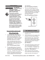
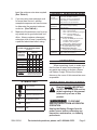
1
BATTERY CHARGER
WITH LCD DISPLAY
65834
Set up and Operating Instructions
Distributed exclusively by Harbor Freight Tools®.
3491 Mission Oaks Blvd., Camarillo, CA 93011
Visit our website at: http://www.harborfreight.com
Read this material before using this product.
Failure to do so can result in serious injury.
Save this manual.
Copyright© 2008 by Harbor Freight Tools®. All rights reserved. No portion of this manual or any artwork
contained herein may be reproduced in any shape or form without the express written consent of
Harbor Freight Tools. Diagrams within this manual may not be drawn proportionally. Due to continuing
improvements, actual product may differ slightly from the product described herein. Tools required for
assembly and service may not be included.
For technical questions or replacement parts, please call 1-800-444-3353.
Save This Manual
NOTICE is used to
address practices
not related to personal injury.
Keep this manual for the safety warnings and precautions, assembly, operating,
inspection, maintenance and cleaning procedures. Write the product’s serial number
in the back of the manual (or month and
year of purchase if product has no number). Keep this manual and the receipt in
a safe and dry place for future reference.
CAUTION, without
the safety alert
symbol, is used to address
practices not related to
personal injury.
General Safety Warnings:
Important SAFETY
Information
WARNING Read all safety
warnings and instructions.
Failure to follow the warnings and
instructions may result in electric
shock, fire and/or serious injury.
Save all warnings and
instructions for future reference.
In this manual, on the labeling,
and all other information provided with this product:
This is the safety alert
symbol. It is used to alert
you to potential personal
injury hazards. Obey all
safety messages that
follow this symbol to avoid
possible injury or death.
1.
Work area safety
a.Keep work area clean and well lit.
Cluttered or dark areas invite accidents.
b.Do not operate this product in
explosive atmospheres, such as in
the presence of flammable liquids,
gases or dust. This product can create sparks which may ignite the dust
or fumes.
c.Keep children and bystanders
away while operating this product.
Distractions can cause you to lose
control.
DANGER indicates
a hazardous
situation which, if not
avoided, will result in death or
serious injury.
WARNING
indicates a
hazardous situation which, if
not avoided, could result in
death or serious injury.
CAUTION, used
with the safety
alert symbol, indicates a
hazardous situation which, if
not avoided, could result in
minor or moderate injury.
SKU 65834
2.
Electrical safety
a.The Power Cord Plug must match
the outlet. Never modify the Plug
in any way. Unmodified plugs and
matching outlets will reduce risk of
electric shock.
b.Avoid body contact with grounded
surfaces such as pipes, radiators,
ranges and refrigerators. There is
For technical questions, please call 1-800-444-3353.
Page 2
an increased risk of electric shock if
your body is grounded.
adjustments, changing accessories, or storing the product.
c.Do not expose this product to rain
or wet conditions. Water entering
this product will increase the risk of
electric shock.
c.Store this product out of the reach
of children and do not allow persons unfamiliar with this product
or these instructions to operate
the unit. Electrically powered products are dangerous in the hands of
untrained users.
d.Do not abuse the Power Cord.
Never use the Cord for carrying,
pulling or unplugging this product. Keep the Cord away from
heat, oil, sharp edges or moving
parts. Damaged or entangled cords
increase the risk of electric shock.
e.This product for use indoors only.
f. If operating this product in a damp
location is unavoidable, use a
Ground Fault Circuit Interrupter
(GFCI) protected supply. Use of
a GFCI reduces the risk of electric
shock.
3.
Personal safety
d.Maintain this product. Check for
breakage of parts and any other
condition that may affect this
product’s operation. If damaged,
have the unit repaired before use.
Many accidents are caused by poorly
maintained products.
e.Use this product and its accessories in accordance with these
instructions, taking into account
the working conditions and the
work to be performed. Use of this
product for operations different from
those intended could result in a hazardous situation.
a.Stay alert, watch what you are doing and use common sense when
using this product. Do not use this 5. Service
product while you are tired or una.Have your Battery Charger serder the influence of drugs, alcohol
viced by a qualified repair person
or medication. A moment of inattenusing only identical replacement
tion while operating this product may
parts. This will ensure that the safety
result in serious personal injury.
of the product is maintained.
b.Do not overreach. Keep proper
footing and balance at all times.
Specific Safety Warnings:
This enables better control of the
power tool in unexpected situations.
1. Maintain labels and nameplates on
the Battery Charger. These carry
4. Product use and care
important safety information. If una.Do not force this product. Use the
readable or missing, contact Harbor
correct product for your applicaFreight Tools for a replacement.
tion. The correct product will do the
2. Wear ANSI-approved safety goggles
job better and safer at the rate for
during set up and use of the Battery
which it was designed.
Charger.
b.Disconnect this product from its
power source before making any
SKU 65834
For technical questions, please call 1-800-444-3353.
Page 3
3.
Do not start a vehicle or turn on a
mobile unit when connected to the
Battery Charger.
4.
When the battery is being charged in
the vehicle, verify that the ignition is
off. Connect the positive (RED with
+) Cable Clamp to the positive (+ or
P) terminal of the battery. Connect
the negative (BLACK with --) to an
unpainted, solid metal portion of the
vehicle. Do not connect to the carburetor or fuel lines.
5.
Charge in a well ventilated area. Explosive gases may be produced during charging. Do not smoke, cause
sparks, or strike matches near the
battery when charging.
6.
Always refer to the user manual of
the battery for charging instructions
and precautions prior to using the
Battery Charger.
7.
Avoid unintentional starting. Prepare
to begin work before turning on the
unit.
8.
Do not leave the Battery Charger
unattended when it is plugged into an
electrical outlet. Unplug the Power
Cord from its power source before
leaving.
9.
• Avoid operating alone.
• Do not use with power switch locked
on.
• Properly maintain and inspect to
avoid electrical shock.
• Any power cord must be properly
grounded. Ground Fault Circuit Interrupter (GFCI) should also be implemented – it prevents sustained electrical shock.
12. WARNING: Handling the Power Cord
on this product will expose you to
lead, a chemical known to the State
of California to cause cancer, and
birth defects or other reproductive
harm. Wash hands after handling.
(California Health & Safety Code §
25249.5, et seq.)
13. The warnings, precautions, and instructions discussed in this instruction
manual cannot cover all possible conditions and situations that may occur.
It must be understood by the operator
that common sense and caution are
factors which cannot be built into this
product, but must be supplied by the
operator.
Save these
instructions.
Do not reverse the polarity of the
Cable Clamps or vehicle battery.
10. This product is not a toy. Keep it out
of reach of children.
11. People with pacemakers should
consult their physician(s) before use.
Electromagnetic fields in close proximity to heart pacemaker could cause
pacemaker interference or pacemaker failure. In addition, people with
pacemakers should:
SKU 65834
For technical questions, please call 1-800-444-3353.
Page 4
Grounding
To prevent
electric shock 3.
and death from
incorrect grounding
wire connection:
Check with a qualified
electrician if you are in doubt
as to whether the outlet is
properly grounded. Do not
modify the Power Cord Plug
provided with the Battery
Charger. Do not use the
Battery Charger if the Power
Cord or Plug is damaged. If
damaged, have it repaired by
a service facility before use. If
the Plug will not fit the outlet,
have a proper outlet installed
by a qualified electrician.
Grounded Tools. Tools with
Three Prong Plugs:
1.
2.
Tools marked with “Grounding Required” have a three wire cord and
three prong grounding plug. The
plug must be connected to a properly
grounded outlet. If the tool should
electrically malfunction or break
down, grounding provides a low resistance path to carry electricity away
from the user, reducing the risk of
electric shock.
(See 3-Prong Plug and Outlet.)
The tool must be plugged into an
appropriate outlet, properly installed
and grounded in accordance with all
codes and ordinances. The plug and
outlet should look like those in the
preceding illustration.
(See 3-Prong Plug and Outlet.)
3-PRONG PLUG & OUTLET
Extension Cords
1.
Grounded tools require a three wire
extension cord.
2.
As the distance from the supply outlet
increases, you must use a heavier
gauge extension cord. Using extension cords with inadequately sized
wire causes a serious drop in voltage,
resulting in loss of power and possible tool damage.
(See Table A.)
3.
The smaller the gauge number of the
wire, the greater the capacity of the
cord. For example, a 14 gauge cord
can carry a higher current than a 16
gauge cord. (See Table A.)
The grounding prong in the plug is
connected through the green wire inside the cord to the grounding system
in the tool. The green wire in the cord 4.
must be the only wire connected to
the tool’s grounding system and must
never be attached to an electrically
SKU 65834
“live” terminal.
(See 3-Prong Plug and Outlet.)
When using more than one extension cord to make up the total length,
make sure each cord contains at
For technical questions, please call 1-800-444-3353.
Page 5
5.
6.
least the minimum wire size required.
(See Table A.)
PRODUCT Specifications
If you are using one extension cord
for more than one tool, add the
nameplate amperes and use the sum
to determine the required minimum
cord size. (See Table A.)
Electrical
Requirements
120 VAC / 60 Hz
Power Cord: 18 AWG x 3C SVT
Power Plug: 3-Prong, Non-Polarized
Output Voltage: 14.4VDC Maximum
Output Current: 6 Amps Maximum
Product
Applications
6VDC or 12VDC Lead-Acid Batteries Only.
(3Ah to 48Ah Charger Capacity)
Indoor Use Only
Features
Three Error Codes Display:
“E01” = Wrong Polarity
“E02” = Disconnected During Charging
“E03” = Damaged Battery or
Not a 6V or 12V Battery
Battery Status Display:
Empty = No Battery/No Connection
One Bar = Battery Connected
Four Bars = Fully Charged
Flashing Bars = Battery Charging
4-Stage Charging Symbol Indicates
2 Amp, 4 Amp, 6 Amp, or Auto
Push Button Starts Charging
Display Shows Charging Voltage
Accessories
Battery Cable Clamps (Qty. 2)
Make sure the extension cord is properly wired and in good electrical condition. Always replace a damaged
extension cord or have it repaired by
a qualified electrician before using.
RECOMMENDED MINIMUM WIRE
GAUGE FOR EXTENSION CORDS*
(120 VOLT)
50’
75’
100’
150’
EXTENSION CORD
LENGTH
25’
NAMEPLATE
AMPERES
0 – 2.0
18
18
18
18
16
2.1 – 3.4
18
18
18
16
14
3.5 – 5.0
18
18
16
14
12
(at full load)
5.1 – 7.0
18
16
14
12
12
7.1 – 12.0
18
14
12
10
-
12.1 – 16.0
14
12
10
-
-
16.1 – 20.0
12
10
-
-
-
TABLE A
* Based on limiting the line
voltage drop to five volts at
150% of the rated amperes.
Symbology
Double Insulated
Canadian Standards Association
Underwriters Laboratories, Inc.
V~
A
Volts Alternating Current
Amperes
No Load Revolutions per Minute
n0 xxxx/min. (RPM)
SKU 65834
Unpacking
When unpacking, check to make sure
that the item is intact and undamaged. If
any parts are missing or broken, please
call Harbor Freight Tools at the number
shown on the cover of this manual as soon
as possible.
Operating Instructions
Read the entire Important
Safety Information section
at the beginning of this manual
before set up or use of this
product.
TO PREVENT
SERIOUS INJURY FROM ACCIDENTAL
OPERATION:
Unplug the Battery Charger from its
power source before performing any
inspection, maintenance, or cleaning
procedures.
For technical questions, please call 1-800-444-3353.
Page 6
Display Features:
1.
2.
3.
Power Switch: Press “ON/OFF”
to start charging. Press “ON/OFF”
again to stop charging.
(See Figure A.)
Charging Rate Selection: Press
“AMPS SELECTION” button to set
charging current. (See Figure A.)
4.
Battery Selection: Press “6V or
12V” for the battery type that is to be
charged. (See Figure A.)
5.
LCD Display of Battery: The LCD
will indicate the battery type (6V or
12V) that has been selected. (See
Figure A.)
6.
LCD Display of Voltage: Before
connecting the battery, the LCD will
display “00.0V”. After connecting
the battery, the LCD will display the
battery voltage. During charging, the
LCD will display the charging voltage.
(See Figure A.)
LCD Display of Charging Current:
The LCD will indicate charging current (2 Amp, 4 Amp, 6 Amp, or Auto)
that has been selected.
(See Figure A.)
POSITIVE (+)
BATTERY CLAMP
CHARGING
SPEED
SELECTION
BATTERY
SELECTION
NEGATIVE (--)
BATTERY CLAMP
LCD DISPLAY
FEATURING:
* CHARGING CURRENT
*BATTERY TYPE
*BATTERY STATUS
*SOUND ALARM
*VOLTAGE
*ERROR SIGNAL
Error Signals:
1.
Under improper polarity, the LCD will
display “E01”. (See Below.)
SKU 65834
2.
POWER
SWITCH
FIGURE A
If battery is disconnected during
charging, the LCD will display “E02”.
(See Below.)
For technical questions, please call 1-800-444-3353.
Page 7
3.
If the battery is not 6 volt or 12 volt,
or the battery is damaged, the LCD
will display “E03”. (See Below.)
4.
Battery Status
1.
If the battery is in the process of
charging, the LCD will display the following: (See Below.)
If the battery is not connected, the
LCD will display the following:
(See Below.)
Sound Alarms:
2.
If the battery is connected, the LCD
will display the following:
(See Below.)
1.
A continuous “beep” indicates wrong
polarity, disconnection during charging, wrong type of battery, dead or
improper battery connection.
2.
A short “beep” occurs each time a
button is pressed.
3.
A short “beep” occurs when connecting or disconnecting the battery.
The Charging Process:
1.
3.
If the battery is fully charged, the LCD
will display the following:
2.
(See next illustration.)
3.
SKU 65834
Remove the battery caps from the
vehicle’s battery to allow any excess
gas to escape and prevent bursting of
the battery.
Check and top off the battery’s liquid.
When the battery being charged is in
the vehicle, verify that the ignition is
off. Connect the positive
(RED with +) Battery Clamp to the
For technical questions, please call 1-800-444-3353.
Page 8
positive (+ or P) terminal of the battery. Connect the negative (BLACK
with --) Battery Clamp to an unpainted, solid metal portion of the vehicle.
Do not connect to the carburetor or
fuel lines.
4.
After the Battery Clamps are connected, slightly rotate the Clamps to
remove any dirt or oxidation layer to
ensure proper contact.
5.
Plug the Power Cord of the Battery
Charger into the nearest 120 volt,
grounded, electrical outlet.
6.
To select the charging speed: Press
the “AMPS SELECTION” button for
maximum charging current.
(See Figure A and Below.)
Charging
Current
Battery
Capacity
Recommended Charging Current
2 Amp
4 Amp
3 ~ 20 Ah
6 ~ 36 Ah
tery Charger will then turn to the next
charging stage under constant voltage.
If “AUTO” is selected, the Battery
Charger starts charging from 2 Amps
until the charging voltage is raised up
to 7.2V volts for a 6 volt battery (motorcycle) or up to 14.4V volts for a 12
volt battery (automobile). The Battery
Charger then turns to the next charging stage (float charging).
2.
Constant voltage stage: The Battery
Charger outputs a constant charging
voltage of 7.2 volts for a 6 volt battery
or 14.4 volts for a 12 volt battery. The
charging current gradually decreases
until it is less than 1 Amp and turns to
the next floating charging stage.
3.
Floating charging stage: The battery
is fully charged and ready to use.
The LCD Display shows the battery
signal which indicates the battery is
fully charged. The Battery Charger
outputs a constant safe voltage of 6.8
volts for a 6 volt battery or 13.6 volts
for a 12 volt battery for floating charging.
6 Amp
12 ~ 48 Ah
7.
To select the battery voltage: Press
the “BATTERY SELECTION” button
(either 6V or 12V). (See Figure A.)
8.
To start the charging process: Press
the “ON/OFF” Power Switch. There
is a short “beep” sound to indicate the
charging has started.
(See Figure A.)
1.
The Charging Stages:
1.
The constant charging stage: Press
the “ON/OFF” Power Switch. The
Battery Charger will run under the
charging current selected until the
charging voltage is raised up to 7.2
volts for a 6 volt battery or up to 14.4
volts for a 12 volt battery. The Bat-
SKU 65834
2.
Disconnecting the Battery
Charger and Battery:
Once the battery is fully charged, disconnect the Power Cord of the Battery Charger from its electrical outlet.
Disconnect the negative (BLACK
with --) Battery Clamp from its unpainted, solid metal portion of the
vehicle. Then disconnect the positive
(RED with +) Cable Clamp (7) from
the positive (+ or P) terminal of the
battery.
For technical questions, please call 1-800-444-3353.
Page 9
(RED with +) Battery Clamp from the
positive (+ or P) terminal of the battery.
3.
Replace the battery caps on the battery.
Maintenance And
Servicing
Procedures not specifically
explained in this manual
must be performed only by a
qualified technician.
aclean, soft cloth for best performance. Do not use solvents, acid, or
alkali products.
4.
WARNING! If the Power Cord is
damaged, it must be replaced only
by a qualified service technician.
PLEASE READ THE
FOLLOWING CAREFULLY
The manufacturer and/or
distributor has provided the
parts list and assembly diagram
in this manual as a reference
To prevent
tool only. Neither the
serious injury
manufacturer or distributor
from accidental
makes any representation
operation OR PRODUCT
or warranty of any kind to
FAILURE:
the buyer that he or she is
Unplug the Power Cord from
qualified to make any repairs
its electrical outlet before
to the product, or that he or
performing any inspection,
she is qualified to replace
maintenance, or cleaning
any parts of the product. In
procedures.
fact, the manufacturer and/
or distributor expressly
Do not use damaged
equipment. If abnormal noise, states that all repairs and
heat, or vibration occurs have parts replacements should
the problem corrected before be undertaken by certified
and licensed technicians, and
further use.
not by the buyer. The buyer
assumes all risk and liability
Inspection, Maintenance, and
arising out of his or her repairs
Cleaning
to the original product or
replacement parts thereto,
1. BEFORE EACH USE, inspect the
or arising out of his or her
general condition of the Battery
installation of replacement
Charger and its accessories. Check
for cracked or broken parts, damaged parts thereto.
electrical wiring, and any other condition that may affect its safe operation.
3.
After Use, clean the surface of
the Battery Charger periodically with
SKU 65834
For technical questions, please call 1-800-444-3353.
Page 10
Problem
Display
Troubleshooting
Possible Causes
Possible Solutions
Battery Charger
will not charge.
1. Screen is not
turned on.
1. No AC power input.
1. Check the plug and power source.
The push buttons
do not work.
1. Screen displays
00.0V.
1. The battery is not connected.
1. Check the battery connections.
2. Screen displays
E01.
2. The polarity connection is
wrong.
2. Make sure the polarity is correct.
1. Screen displays
E02.
1. The battery is disconnected
during charging.
1. Check the battery connection. Then
resume charging.
2. Screen displays
E03.
2. The battery is not 6V or 12V.
2. Make sure battery is 6V or 12V.
3. The battery is too low in
voltage. (6V battery is less
than 5.2V; 12V battery is less
than 10.5V)
3. If the battery is deeply discharged, wait
for a while until it automatically turns back
above 5.2V for a 6V battery or above 10.5V
for a 12V battery.
4. The battery is damaged.
4. If the battery is in low voltage status for a
long time, then it is possibly damaged and
needs to be replaced with a new battery.
1. AC power supply is not
stable. Battery has hidden
defect which prevents the
Battery Charger from normal
resetting.
1. Disconnect the power supply, then
reconnect again. If the faulty situation
occurs during charging, try another similar
battery to determine if it is a battery
problem or power supply problem.
There is a
continuous
“beep” sound.
Abnormal
situation.
1. No display
on screen, or
abnormal display
on screen.
Follow all safety precautions whenever diagnosing or servicing this
product. Disconnect power supply before service.
PARTS LIST
Part #
Qty.
Part #
1
Upper Housing
Description
1
16
Sticker
Description
Qty.
1
2
Lower Housing
1
17
Socket
1
3
Battery Selection Button
1
18
Radiator Board (B)
1
4
Charging Speed Selection Button
1
19
Rivet
2
5
Power Switch
1
20
Welding Slice
1
6
Decorative Board
1
21
Screw (M3 x 6)
1
7
Screen Cover
1
22
Nut (M3)
1
8
Label
1
23
Screw (M3 x 6)
2
9
LCD
1
24
Nut (M3)
2
10
Back Board
1
25
Screw (ST2 x 4)
4
11
Display Feature Circuit Board
1
26
Screw (ST2 x 4)
4
12
Main Function Circuit Board
1
27
Screw (ST3 x 5)
3
13
Key Board Function Circuit Board
1
28
Power Cord
1
14
Key Board Spring
3
29
Battery Clamp
2
15
Radiator Board (A)
1
30
Screw (ST3 x 30)
4
SKU 65834
For technical questions, please call 1-800-444-3353.
Page 11
ASSEMBLY DIAGRAM
SKU 65834
For technical questions, please call 1-800-444-3353.
Page 12
LIMITED 90 DAY WARRANTY
Harbor Freight Tools Co. makes every effort to assure that its products meet high
quality and durability standards, and warrants to the original purchaser that this product is free from defects in materials and workmanship for the period of 90 days from
the date of purchase. This warranty does not apply to damage due directly or indirectly,
to misuse, abuse, negligence or accidents, repairs or alterations outside our facilities,
criminal activity, improper installation, normal wear and tear, or to lack of maintenance.
We shall in no event be liable for death, injuries to persons or property, or for incidental,
contingent, special or consequential damages arising from the use of our product. Some
states do not allow the exclusion or limitation of incidental or consequential damages, so
the above limitation of exclusion may not apply to you. This warranty is expressly in lieu of all other warranties, express or implied, including the
warranties of merchantability and fitness.
To take advantage of this warranty, the product or part must be returned to us with
transportation charges prepaid. Proof of purchase date and an explanation of the complaint must accompany the merchandise. If our inspection verifies the defect, we will either repair or replace the product at our election or we may elect to refund the purchase
price if we cannot readily and quickly provide you with a replacement. We will return repaired products at our expense, but if we determine there is no defect, or that the defect
resulted from causes not within the scope of our warranty, then you must bear the cost
of returning the product.
This warranty gives you specific legal rights and you may also have other rights
which vary from state to state.
3491 Mission Oaks Blvd. • PO Box 6009 • Camarillo, CA 93011 • (800) 444-3353
Record Product’s Serial Number Here:
Note: If product has no serial number, record month and year of purchase instead.
Note: Some parts are listed and shown for illustration purposes only, and are not available individually as replacement parts.
SKU 65834
For technical questions, please call 1-800-444-3353.
Page 13