1
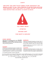
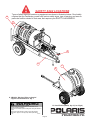
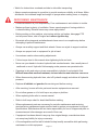
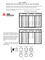
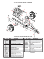
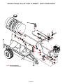
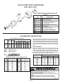
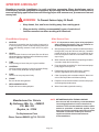
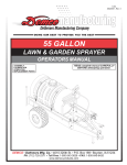
11-02 AS20022, Rev 0 30 & 55 GALLON LAWN & GARDEN SPRAYER OPERATORS MANUAL ASSEMBLY CALIBRATION OPERATION REPLACEMENT PARTS READ complete manual CAREFULLY BEFORE attempting operation. Page 1 Page 2 Thank you for purchasing a Polaris sprayer. We feel you have made a wise choice and hope you are completely satisfied with your new sprayer. If you have any questions regarding the applications of certain solutions or chemicals, contact your chemical supplier and follow chemical manufacturer recommendations as well as all licensing and use restrictions or regulations. WARNING To prevent serious injury or death ï Refer to chemical supplier and manufacturer recommendations and all licensing restrictions or regulations. ï Always wear recommended protective clothing when working with chemicals or sprayer. ï Dispose of all unused chemicals or solutions in proper and ecologically sound manner. Improper use can injure people, animals, plants and soil. GENERAL INFORMATION 1. Unless otherwise specified, high-strength (grade5) (3 radial-line head markings) hex head bolts are used throughout assembly of this sprayer. 3. When placing a parts order, refer to this manual for proper part numbers and place order by PART NO., DESCRIPTION, and COLOR. 2. Whenever terms "LEFT" and "RIGHT" are used in this manual it means from a position behind sprayer and facing forward. Table of Contents General information ........................................................................................................................... 3 Safety , Signal Words ........................................................................................................................ 4 Equipment Safety Guidelines ............................................................................................................ 5 Lighting and Marking ......................................................................................................................... 5 Safety Sign Locations ........................................................................................................................ 6 Safety Sign Care ............................................................................................................................... 7 Tire Safety .......................................................................................................................................... 7 Remember ......................................................................................................................................... 7 Before Operation .............................................................................................................................. 7-8 During Operation .............................................................................................................................. 8-9 Following Operation .......................................................................................................................... 9 Highway and Transport Operations ................................................................................................ 10-11 Performing Maintenance .................................................................................................................. 11 Bolt Torque ........................................................................................................................................ 12 55 Gallon Skid Mount with the Trailer Kit Parts Breakdown and Parts List ...................................... 13 Gas Engine Roller Pump Plumbing Parts Breakdown and Parts List ........................................... 14-15 Gas Engine Roller Pump Operating Instructions ............................................................................. 15 25 Gallon Trailer Sprayer Parts Breakdown and Parts List ............................................................ 16-17 3 G.P.M. Electric Pump Plumbing Parts Breakdown and Parts List ................................................. 18 80î Boom Parts Breakdown and Parts List (55 Gallon) ................................................................... 19 12í and 18í Parts Breakdown and Parts List .................................................................................... 20 80 Boom Parts Breakdown and Parts List (25 Gallon) ................................................................... 21 12 and 18 Boom Parts Breakdown and Parts List ......................................................................... 22 Spray Wand and 3 G.P.M. Electric Pump Parts Breakdowns and Parts Lists .................................. 23 C4101 & XL4101 Roller Pump Parts Breakdown and Parts List ..................................................... 24 Bypass Valve and Direct-o-Valve Parts Breakdowns and Parts Lists .............................................. 25 Sprayer Calibration Instructions ....................................................................................................... 26 Sprayer Checklist ............................................................................................................................. 27 Page 3 SAFETY TAKE NOTE! THIS SAFETY ALERT SYMBOL FOUND THROUGHOUT THIS MANUAL IS USED TO CALL YOUR ATTENTION TO INSTRUCTIONS INVOLVING YOUR PERSONAL SAFETY AND SAFETY OF OTHERS. FAILURE TO FOLLOW THESE INSTRUCTIONS CAN RESULT IN INJURY OR DEATH. THIS SYMBOL MEANS ATTENTION BECOME ALERT YOUR SAFETY IS INVOLVED! SIGNAL WORDS Note: use of the following signal words DANGER, WARNING, and CAUTION with safety messages. Appropriate signal word for each has been selected using following guidelines: DANGER: Indicates an imminently hazardous situation that, if not avoided, will result in death or serious injury. This signal word is to be limited to most extreme situations typically for machine components which, for functional purposes, cannot be guarded. WARNING: Indicates a potentially hazardous situation that, if not avoided, could result in death or serious injury, and includes hazards that are exposed when guards are removed. It may also be used to alert against unsafe practices. CAUTION: Indicates a potentially hazardous situation that, if not avoided, may result in minor or moderate injury. It may also be used to alert against unsafe practices. If you have questions not answered in this manual , require additional copies, or if your manual is damaged, please contact your dealer or Dethmers Mfg. Co., P.O. Box 189, 4010 320th Street, Boyden, IA 51234 ph: (712) 725-2311 or Toll Free: 1-800-543-3626 Fax: (712) 725-2380 http://www.demco-products.com Page 4 SAFETY...YOU CAN LIVE WITH IT EQUIPMENT SAFETY GUIDELINES Every year many accidents occur which could be avoided by a few seconds of thought and more careful approach to handling equipment. You, the operator, can avoid accidents by observing precautions in this section. To avoid personal injury, study precautions and insist those working with you, or you yourself, follow them. In order to provide a better view, certain illustrations in this manual may show an assembly with a safety shield removed. However, sprayer should never be operated in this condition. Keep all shields in place. If shield removal becomes necessary for repairs, replace shield prior to use. Replace any caution, warning, danger or instruction safety decal that is not readable or is missing. Location of such decals is indicated in this booklet. Do not attempt to operate this sprayer under the influence of alcohol or drugs. Review safety instructions with all users. Operator should be a responsible adult. DO NOT ALLOW PERSONS TO OPERATE OR ASSEMBLE THIS SPRAYER UNTIL THEY HAVE DEVELOPED A THOROUGH UNDERSTANDING OF SAFETY PRECAUTIONS AND HOW IT WORKS. To prevent injury or death, use a tractor equipped with a roll over protective system (ROPS). Do not paint over, remove, or deface any safety signs or warning decals on your sprayer. Observe all safety signs and practice instructions on them. Never exceed limits of sprayer. If its ability to do a job, or to do so safely is in question DON'T TRY IT. LIGHTING AND MARKING It is the responsibility of operator to know lighting and marking requirements of local highway authorities and to install and maintain equipment to provide compliance with regulations. Add extra lights when transporting at night or during periods of limited visibility. Lighting kits are available from your dealer or manufacturer. Page 5 SAFETY SIGN LOCATIONS B Types of safety sign and locations on equipment are shown in illustration below. Good safety requires that you familiarize yourself with various safety signs, type of warning, and area or particular function related to that area, that requires your SAFETY AWARENESS. A B B A B A. AB21014 - Warning: Refer to chemical supplier and manufacturer Qty. 1 WARNING B. Small Polaris (White) Qty. 4 (3 on 55 gal.) To prevent serious injury or death • Refer to chemical supplier and manufacturer recommendations and all licensing restrictions or regulations. • Always wear recommended protective clothing when working with chemicals or sprayer. • Dispose of all unused chemicals or solutions in proper and ecologically sound manner. Improper use can injure people, animals, plants and soil. 01/00 AB21014 Page 6 SAFETY SIGN CARE Keep safety signs clean and legible at all times. Replace safety signs that are missing or have become illegible. Replacement parts that displayed a safety sign should also display current sign. Safety signs are available from your distributor, dealer parts department, or manufacturer. How to install safety signs: Be sure installation area is clean and dry. Decide on exact position before you remove backing paper. Remove smallest portion of split backing paper. Align decal over specified area and carefully press small portion with exposed sticky backing in place. Slowly peel back remaining paper and carefully smooth remaining portion of decal into place. Small air pockets can be pierced with a pin and smoothed out using piece of decal backing paper. TIRE SAFETY Failure to follow proper procedures when mounting tire on rim can produce an explosion resulting in serious injury or death. Do not attempt to mount tire unless you have proper equipment and experience. Inflating or servicing tires can be dangerous. Whenever possible, trained personnel should be called to service or mount tires. Always order and install tires and wheels with appropriate type and load capacity to meet or exceed anticipated weight to be placed on sprayer. REMEMBER Your best assurance against accidents is a careful and responsible operator. If there is any portion of this manual or function you do not understand, contact your local authorized dealer or manufacturer. BEFORE OPERATION: Carefully study and understand this manual. Do not wear loose-fitting clothing which may catch in moving parts. Always wear protective clothing and substantial shoes. It is recommended that suitable hearing and eye protection be worn. Operator may come in contact with certain materials which may require specific safety equipment relative to handling of such materials. (Examples: extremely dusty, molds, fungus, bulk fertilizers, etc.) Page 7 Keep wheel and lug nuts tightened to specified torque. Assure that agricultural implement tires are inflated evenly. Give sprayer a visual inspection for any loose bolts, worn parts, or cracked welds, and make necessary repairs. Follow maintenance safety instructions included in this manual. Be sure there are no tools lying on or in equipment Do not use the sprayer until you are sure that area is clear, especially around children and animals. Don't hurry learning process or take sprayer for granted. Ease into it and become familiar with your new equipment. Practice operation of your sprayer and its attachments. Completely familiarize yourself and other operators with its operation before using. Use a tractor equipped with Roll Over Protection System (ROPS) and fasten your seat belt prior to starting engine. Manufacturer does not recommend usage of tractor with ROPS removed. Move tractor wheels to widest recommended settings to increase stability. Do not allow anyone to stand between tongue or hitch and towing unit when backing up to equipment. DURING OPERATION Beware of bystanders, PARTICULARLY CHILDREN! Always look around to make sure it is safe to start engine of towing unit or move sprayer. This is particularly important with higher noise levels and quiet cabs, as you may not hear people shouting. NO PASSENGERS ALLOWED- Do not carry passengers anywhere on or in the tractor or sprayer. Keep hands and clothing clear of moving parts. Do not clean, lubricate, or adjust your sprayer while it is moving. When halting operation, even periodically, set tractor or towing unit brakes, disengage PTO, shut off engine, and remove ignition key. Be especially observant of operating area and terrain- watch for holes, rocks, or other hidden hazards. Always inspect area prior to operation. - DO NOT operate near edge of drop-offs or banks. - DO NOT operate on steep slopes as overturn may result. - Operate up and down (not across) intermediate slopes. Avoid sudden starts and stops. Page 8 Pick the most level possible route when transporting across fields. Avoid edges of ditches, gullies, and steep hillsides. Be extra careful when working on inclines. Periodically clear equipment of brush, twigs, or other materials to prevent buildup of dry combustible materials. Maneuver tractor or towing unit at safe speeds. Avoid overhead wires or other obstacles. Contact with overhead lines could cause serious injury or death. Avoid loose gravel, rocks, and holes; they can be dangerous for equipment operation or movement. Allow for sprayer length when making turns. Do not walk or work under raised components or attachments unless securely positioned and blocked. Keep all bystanders, pets, and livestock clear of work area. Operate towing unit from operators seat only. Never stand alongside of unit with engine running or attempt to start engine and/or operate machine while standing alongside of unit. Never leave running equipment attachments unattended. As a precaution, always recheck hardware on equipment following every 100 hours of operation. Correct all problems. Follow maintenance safety procedures. FOLLOWING OPERATION Following operation, or when unhitching, stop tractor or towing unit, set brakes, disengage PTO and all power drives, shut off engine and remove ignition key. Store sprayer in an area away from human activity. Do not park sprayer where it will be exposed to livestock for long periods of time. Damage and livestock injury could result. Do not permit children to play on or around the stored sprayer. Make sure all parked machines are on a hard, level surface and engage all safety devices. Wheel chocks may be needed to prevent unit from rolling. Page 9 HIGHWAY AND TRANSPORT OPERATIONS SAFETY CHAINS: If equipment is going to be transported on a public highway, always follow state and local regulations regarding safety chains and auxiliary lighting. Be sure to check with local law enforcement agencies for your own particular regulations. If required safety chains should be obtained and installed. Only safety chains (not elastic or nylon/plastic tow straps) should be used to retain connection between towing and towed machines in event of separation of primary attaching system. Use a high strength, appropriately sized hitch pin with a mechanical retainer and attach safety chains. Criss cross chains under tongue and secure to draw bar cage, mounting loops, or bumper frame. Adopt safe driving practices: - Keep brake pedals latched together at all times. NEVER USE INDEPENDENT BRAKING WITH SPRAYER IN TOW. LOSS OF CONTROL OR UPSET MAY RESULT. - Always drive at a safe speed relative to local conditions and ensure that your speed is low enough for an emergency stop. Keep speed to a minimum. - Reduce speed prior to turns to avoid risk of overturning. - Always keep tractor or towing unit in gear to provide engine braking when going downhill. Do not coast. - Do not drink and drive! Comply with state and local laws governing highway safety and movement of farm machinery on public roads. Use approved accessory lighting flags and necessary warning devices to protect operators of other vehicles on highway during transport. Various safety lights and devices are available from your dealer. Use of flashing amber lights is acceptable in most localities. However, some localities prohibit their use. Local laws should be checked for all highway lighting and marking requirements. When driving tractor and sprayer under 20 mph (40 kph) day or night, use flashing amber warning lights and a slow moving vehicle (SMV) identification emblem. Plan your route to avoid heavy traffic. Be a safe and courteous driver. Always yield to oncoming traffic in all situations, including narrow bridges, intersections, etc. Be observant of bridge load ratings. Do not cross bridges rated lower than gross weight of unit you are operating. Page 10 Watch for obstructions overhead and side to side while transporting. Always operate equipment in a position to provide maximum visibility at all times. Make allowances for increased length and weight of sprayer when making turns, or stopping. PERFORMING MAINTENANCE Good maintenance is your responsibility. Poor maintenance is an invitation to trouble. Make sure there is plenty of ventilation. Never operate engine of towing vehicle in a closed building. Exhaust fumes may cause asphyxiation. Before working on this machine, stop towing vehicle, set brakes, disengage PTO and all power drives, shut off engine and remove ignition key. Be certain all moving parts and attachments have come to a complete stop before attempting to perform maintenance. Always use a safety support and block wheels. Never use a jack to support machine. Always use proper tools or equipment for job at hand. Use extreme caution when making adjustments. Follow torque chart in this manual when tightening bolts and nuts. Never use your hands to locate a hydraulic leak on attachments. Use a small piece of cardboard or wood. Hydraulic fluid escaping under pressure can penetrate skin. Openings in skin and minor cuts are susceptible to infection from hydraulic fluid. Without immediate medical treatment, serious infection and reactions can occur. When disconnecting hydraulic lines, shut off hydraulic supply and relieve all hydraulic pressure. Replace all shields and guards after servicing and before moving. After servicing, be sure all tools, parts and service equipment are removed. Do not allow grease or oil to build up on any steps or platform. When replacing bolts refer to owners manual. Refer to bolt torque chart for head identification marking. Where replacement parts are necessary for periodic maintenance and servicing, genuine factory replacement parts must be used to restore your equipment to original specifications. Manufacturer will not claim responsibility for use of unapproved parts or accessories and other damages as a result of their use. If equipment has been altered in any way from original design, manufacturer does not accept any liability for injury or warranty. A fire extinguisher and first aid kit should be kept readily accessible while performing maintenance on this equipment Page 11 BOLT TORQUE TORQUE DATA FOR STANDARD NUTS, BOLTS, AND CAPSCREWS. Tighten all bolts to torques specified in chart unless otherwise noted. Check tightness of bolts periodically, using bolt chart as guide. Replace hardware with same grade bolt. NOTE: Unless otherwise specified, high-strength Grade 5 hex bolts are used throughout assembly of equipment. Bolt Torque for Standard bolts * Torque Specifications A GRADE 2 lb-ft (N.m) GRADE 5 lb-ft (N.m) GRADE 8 lb-ft (N.m) 1/4 5/16 3/8 7/16 1/2 9/16 5/8 3/4 7/8 1 6 10 20 30 45 70 95 165 170 225 9 18 30 50 75 115 150 290 420 630 12 25 45 80 115 165 225 400 650 970 (8) (13) (27) (40) (60) (95) (130) (225) (230) (300) (12) (25) (40) (70) (100) (155) (200) (390) (570) (850) (16) (35) (60) (110) (155) (220) (300) (540) (880) (1310) Bolt Torque for Metric bolts * A Torque figures indicated are valid for non-greased or non-oiled threads and heads unless otherwise specified. Therefore, do not grease or oil bolts or capscrews unless otherwise specified in this manual. When using locking elements, increase torque values by 5%. * GRADE or CLASS value for bolts and capscrews are identified by their head markings. 6 7 8 10 12 14 16 18 20 22 24 CLASS 8.8 lb-ft (N.m) CLASS 9.8 lb-ft (N.m) CLASS 10.9 lb-ft (N.m) 9 15 23 45 78 125 194 268 378 516 654 10 18 25 50 88 140 216 ----- 13 21 31 61 106 170 263 364 515 702 890 (13) (21) (31) (61) (106) (169) (263) (363) (513) (699) (886) GRADE-2 GRADE-5 (14) (24) (34) (68) (118) (189) (293) ----- GRADE-8 CLASS 8.8 CLASS 9.8 CLASS 10.9 8.8 Page 12 9.8 10.9 (17) (29) (42) (83) (144) (230) (357) (493) (689) (952) (1206) 55 GALLON SKID MOUNT SPRAYER 18 3 4 1 17 5 8 14 6 16 7 12 7 2 11 7 9 28 13 9 24 7 19 26 29 7 19 10 7 9 21 7 26 20 19 7 9 22 27 25 23 55 GALLON SPRAYER FRAME PARTS LIST REF. NO. 1. 2. 3. 4. 5. 6. 7. 8. 9. 10. 11. 12. 13. 14. 15. 16. 17. 18. 20. 29. PART QTY. REF. PART QTY. NO. REQD DESCRIPTION NO. NO. REQD DESCRIPTION 5316 2 50" Strap Assembly 19. 00059 8 3/8" Flatwasher 20. 00095 4 3/8-16 UNC x 3/4" Sq. Hd. Set Screw 00004 2 5/16î Flatwasher 7. 00907 14 3/8"-16 UNC x 1" Hex Head Bolt 02802 2 5/16"-18 UNC Nylon Insert Locknut 21. 01404-95 1 Lock Handle 04352 2 5/16"-18 UNC x 4" F.T. Hex Hd. Bolt 9. 02592 14 3/8"-16 UNC Nylon Insert Locknut 04353 50" Nylon Strap Black 22. 02626-10 1 Tongue 05785-95 2 Small Strap Anchor - 1-3/4" Strap 23. 02627-10 1 Clevis Hitch 00214 4 1/4 Flatwasher 24. 02628-10 1 Axle 00907 8 3/8"-16 UNC x 1" Hex Head Bolt 25. 02629-10 1 Safety Stand 00955 2 1/4"-20 UNC x 1" Round U-Bolt 26. 02635-95 4 Wheel Space Collar 02592 12 3/8"-16 UNC Nylon Insert Locknut 27. TW18X8 2 18" x 9-1/2 x 8", 2 ply High Flotation 02625-10 1 Trailer Main Frame Tire and Hub 02630-10 1 Right Hose Storage Bracket 02642 1 Bearing (only) 02631-10 1 Left Hose Storage Bracket 02643 2 Retainer (only) 02632-10 1 Control Valve Mount 28. 02669-10 1 Valve Mount (red) 02633-10 1 Right Boom Mount 02634-10 1 Left Boom Mount (not shown) Please order replacement parts by PART NO., COLOR, and 02772 4 1/4"-20 UNC Nylon Insert Locknut DESCRIPTION. P55 23 1 55 gal. Poly Tank P55 23A 1 55gal. Poly Tank w/ Agitation Installed PL5A 1 5" Cover for tank 00095 1 3/8-16 UNC x 3/4" Sq. Hd. Set Screw 02529 2 3/8-16 UNC x 2-1/2 Round U-Bolt Page 13 ENGINE DRIVEN ROLLER PUMP PLUMBING PARTS BREAKDOWN 41 40 17 24 27 42 20 27 16 19 37 B 11 36 19 20 26 18 31 28 39 33 27 A 26 32 27 15 23 21 C 33 25 30 39 22 2 18 34 32 26 18 18 26 30 32 26 8 26 28 26 a 33 30 13 b 14 34 c 32 18 38 d 5 10 26 18 3 9 26 28 35 D 26 29 7 30 39 1 12 9 30 18 4 33 9 26 NOTE: Use thread sealant on all threaded fittings. Page 14 10 6 32 32 34 ENGINE DRIVEN ROLLER PUMP PLUMBING PARTS LIST REF. NO. 1. 2. 3. 4. 5. 6. 7. 8. 9. 10. 11. 12. 13. 14. 15. 16. 17. 18. 19. 20. 21. 22. 23. 24. 25. 26. 27. 28. 29. 30. PART QTY. NO. REQD DESCRIPTION 00036 2 5/16" Lockwasher 00214 4 1/4" Flatwasher 00372 4 5/16"-18 UNC x 1-1/2" Hex Head Bolt 01872 2 Rubber Bumper 02653-70 1 Pump Drive Shaft Shield 02658-10 1 Engine Mounting Plate 02660-70 1 Pump Mounting Bracket 02772 4 1/4"-20 UNC Nylon Insert Locknut 02802 9 5/16-18 UNC Nylong Insert Locknut 02990 5 5/16-18 UNC x 1 Hex Head Bolt 04055 4 1/4-20 UNC x 1 Hex Head Bolt 04305 2 5/16"-18 UNC x 1/2" Hex Head Bolt 04880-95 1 Pump Coupler 07174 4 Coupler Set Screws 120RB 1/2" I.D Rubber Hose 160GB 1 160 lb. Brass Pressure Gauge 30L-18PP 1 18" Hand Spray Gun w/adj. Tip 340RB 3/4" I.D Rubber Hose 380RB 3/8" I.D. Rubber Hose 5044 1 1 Single Agitation Wand Assembly 6B1 1 Direct - o - valve 8460 1 3/4" MPT Pressure Relief Valve A1238 1 1/2" MPT x 3/8" Hose Barb A1438 1 1/4 MPT x 3/8 Hose Barb A3438 1 3/4" MPT x 3/8" Hose Barb B12H 12 3/4" Hose Clamp SS B6H 6 3/8" Hose Clamp SS GE3HP 1 3-1/2 H.P. Briggs Gas Engine BA3412 1 3/4" MPT x 1/2" Hose Barb BA3434 5 3/4" MPT x 3/4" Hose Barb REF. NO. 31. 32. 33. 34. 35. 36. 37. 38. a. b. c. d. 39. 40. 41. Please order replacement parts by PART NO. and DESCRIPTION. OPERATING INSTRUCTIONS 1. Fill the tank with water. 2. Open the Ball valve (A) in the pump intake line. 3. Open (counter clockwise) the pressure relief valve (B). 4. Open the Tee valve (C) so that the boom is spraying. 5. Open the agitation valve (D). 6. Start and run pump. 7. Slowly close the pressure relief valve (B) until the desired spraying pressure is reached with the boom spraying. 8. If adequate spraying pressure cannot be reached, slowly close the agitation valve (D) until the desired spraying pressure is reached. 9. Check for leaks. PART QTY. NO. REQD DESCRIPTION BEL1212 1 1/2" MPT x 1/2" Hose Barb Elbow BEL3434 6 3/4" MPT x 3/4" Hose Barb Elbow BM3400 4 3/4" MPT Nipple BTT34 3 3/4" FPT Tee C4101 1 Cast Iron Roller Pump EL114 34 1 1-1/4" MPT x 3/4" Hose Barb Elbow M1200 1 1/2" MPT Short Nipple RVF34 80 1 3/4" Line Strainer w/80 mesh screen RVF34C 1 3/4" Strainer Cup RVF380 1 80 Mesh Screen for 3/4" Strainer RVF34GV 1 Viton O-ring for 3/4" Strainer RVF34B 1 Strainer Bowl UV075FP 3 3/4" Poly Ball Valve P55 23AP 1 55gal. Poly Tank w/ Agitation Installed PL5A 1 5" dia. Lid Page 15 30 GALLON TRAILER SPRAYER PARTS BREAKDOWN 10 9 1 22 22 25 23 14 24 11 16 1 11 7 8 15 6 8 6 7 7 7 8 1 12 17 8 8 8 13 4 5 7 21 6 1 7 7 3 6 19 18 1 8 3 26 5 7 21 1 8 6 5 3 3 4 2 20 5 Page 16 TRAILER SPRAYER PARTS LIST REF. NO. PART NO. QTY. REQD 1. 2. 3. 4. 5. 6. 7. 8. 9. 10. 11. 12. 13. 14. 15. 16. 17. 18. 19. 20. 21. 22. 23. 24. 25. 26. 00004 00909 00955 02363 02534 02772 02802 02990 04352 04353 04822 05758-70 05759-70 05767-70 05772-70 05773-70 05777-70 05778-70 05779-70 05780-10 05781-70 05785-95 07875 P25 23P PL5A TW15X6 18 1 4 2 4 12 20 14 4 2 2 1 1 1 1 1 1 1 1 1 2 4 2 1 1 2 DESCRIPTION 5/16" Flatwasher 5/16"-18 UNC x 1-3/8" x 1-7/8" Square U-bolt 1/4"-20UNC x 1" x 2" Round U-bolt Cotter Pin (5/32" x 1-1/4") 3/4" Machine Washer 1/4"-20 UNC Nylon Insert Locknut 5/16"-18 UNC Nylon Insert Locknut 5/16-18 UNC x 1" Hex Head Bolt 5/16"-18 UNC x 4" Hex Hd. Bolt Full Thread 1-3/4" Black Polyester Strap 50" Long 1/4"-20 UNCx 1" x 1-1/2" Square U-bolt Left Side Frame Right Side Frame Control Valve Mount Left Boom Mount Right Boom Mount Top Cross Plate Bottom Cross Plate Axle Tongue (36" lg.) Bottom Frame (21" lg.) Small Strap Anchor 1" Square Cap 30 Gal. (includes Lid) Lid 2-Ply 15" Rubber Tire (includes rim & wheel bearings) PLEASE ORDER REPLACEMENT PARTS BY PART NO. AND DESCRIPTION. Page 17 PARTS LIST REF. NO. 1. 2. 3. 4. 5. 6. 7. 8. 9. 10. 11. 12. 13. 14. 15. 16. 17. 18. 19. 20. 21. 22. 23. 24. 25. 26. 27. 28. 29. a. b. c. d. 30. ELECTRIC PUMP PLUMBING PARTS BREAKDOWN NOTE: See page 26 for Spray Gun Assembly Breakdown. 16 10 14 20 21 15 15 21 PART NO. 00214 00336 00955 01013 02772 03900 04055 04755-95 04764 05595-70 120RB 2088 343 135 23120PP 30L-6PP 380RB 5500 6PP 100GB A1212SF BA1212 A1438 B6H BEL1212 BEL3412 BM1238 BTT12G EL1212SF EL1438 EL3838 RVB12 80 RVF38C RVB80 RVB38GE RVB38B T12 3 21 22 25 b 28 a 29 21 24 23 21 13 21 30 9 19 21 11 21 11 21 11 1/4" Flatwasher 1/4"-20 UNC x 1-1/4" Hex Hd. Bolt 1/4"-20 UNC 2" Rd. U-bolt Toggle Switch 1/4"-20 UNC Nylon Insert Locknut 3/8" MPT x 3/8" FPT Ball Valve 1/4"- 20UNC x 1" Hex Head Bolt Switch Mount 10 ft. Wire Harness Assembly Handgun Storage Bracket 1/2" I.D. Rubber Hose Electric 12 VDC Pump (3 gal. per min.) 1/2" NPT Pressure Relief Valve 18" Low Pressure Spray Gun 3/8" I.D. Rubber Hose Adjustable Spray Tip 100 lb. Brass Pressure Gauge 1/2" MPT x 1/2" Hose Barb Elbow 1/2" MPT x 3/8" Hose Barb 1/4" MPT x 3/8" Hose Barb 3/8" Gear Clamp 1/2" MPT x 1/2" Hose Barb Elbow 3/4" MPT x 1/2" Hose Barb Elbow 1/2" MPT x 1/4" FPT Reducer Fitting 1/2" FPT Tee 1/2" MPT x 1/2" Hose Barb Elbow 1/4" MPT x 3/8" Hose Barb Elbow 3/8" MPT x 3/8" Hose Barb Elbow Strainer Assembly w/ 80 mesh screen 1/2 Strainer Cup 80 Mesh Screen for 1/2 Strainer Viton 0-Ring Strainer Bowl 1/2" Hose Barb Tee c 6 17 11 4 4 1 1 7 1 1 1 1 1 1 1 1 1 1 1 1 1 14 1 1 1 1 1 1 1 1 1 1 1 1 1 DESCRIPTION 21 d 27 QTY. 11 12 1 21 5 2 21 21 7 4 26 8 5 5 OPERATING INSTRUCTIONS 1. Fill the tank with water. 2. Open (counter clockwise) the pressure relief valve (B). 3. Open a valve (C) so that the boom is spraying. 4. Start and run pump. 5. Slowly close the pressure relief valve (B) until the desired spraying pressure is reached with the boom spraying. 6. Check for leaks. NOTE: Use thread sealant on all threaded fittings. Page 18 18 12' & 18í BOOM (DB12-10 & DB18-10) PARTS BREAKDOWN 23 25 4 17 3 10 5 1 3 10 12 24 8 23 14 26 23 10 15 16 6 30 22 11 15 18 9 2 20 7 19 21 1 29 23 24 DB12-10 & DB18-10 PARTS LIST 23 REF. NO. 13 NOTE: The mounting brackets (#14) and attaching hardware are used to mount the 18' Boom in the same manner. DB18 HINGE ASSEMBLY 5 4 15 9 15 27 7 10 2 7 PART NO. QTY. REQD PART NO. QTY. REQD DB12-10 00004 11137 00340-95 00357 00640 00909 00967 01564 02592 02636-10 02637-10 02638-10 02678-95 02772 02529 380RB 1. 2. 4. 5. 6. 7. 8. 9. 10. 11. 12. 13. 14. 15. 17. 18. 19. 4193APP50 28 20. 8027 21. AN1.5 23. B6H 24. NHT11 25. NTL38 26. NTT38 27. 28. 29. T38 1 4 4 2 2 2 2 2 2 4 1 1 1 2 8 2 4 4 4 8 5 2 2 1 1 4 4 2 4 2 5 2 4 4 1 1 1 2 8 2 4193APP50 6 8027 6 AN1.5 6 B6H 12 NHT11 7 NTL38 2 NTT38 4 03674-10 2 03676-10 1 T38 1 12' & 18' Boom Assembly(Red) 5/16 Flatwasher 3/8î Clinch Nut (inclíd with 00340-95) Wing Hinge Pin (includes one 11137) 3/8"-16 UNC x 4-1/2" Tension Bolt 1/2-13 UNC Jam Nut 5/16" x 1-3/8" Sq. U-bolt 1/2-13 UNC x 1-1/4 Hex Head Bolt Spring 3/8"-16 UNC Nylon Insert Locknut Center Boom Section Right Wing Section Left Wing Section Boom Mounting Plate 1/4"-20 UNC Nylon Insert Locknut 3/8"-16 UNC x 1-1/2" Round U-bolt 3/8" I.D. Rubber Hose 5 PSI Ball Check Valve 11/16" FPS Swivel Nut Flood Jet Spray Tip 3/8" Gear Clamp Hose Tie 3/8" Elbow Spray Nozzle Fitting w/nut 3/8" Tee Nozzle Fitting w/nut Spring Anchor Angle (DB18 Only) Boom Support Plate (DB18 Only) 3/8" Insert Tee B11 114 30. 00062 16. 00068 22. 00337-95 4 1 1 2 B11 114 00062 00068 00337-95 1-1/4 Boom Clamp Assembly 1/4"-20 UNC Nut 1/4"-20 UNC x 3/4" Hex Hd. Bolt 1-1/4" Boom Clamp DB18-10 00004 11137 00340-95 00357 00640 00909 00967 01564 02592 03673-10 03675-10 03680-10 02678-95 02772 02529 380RB 6 1 1 2 DESCRIPTION Please order replacement parts by PART NO. and DESCRIPTION. Page 19 12' AND 18' BOOM ASSEMBLY PARTS BREAKDOWN NOTE: Boom shown below is model DB12 12 foot boom. 31 23 25 30 21 4 18 9 12 5 18 17 16 14 6 10 7 9 2 30 21 32 22 3 15 7 20 8 23 26 31 23 1 14 19 24 20 19 23 11 24 29 23 REF. NO. 13 NOTE: The mounting brackets (#14) and attaching hardware are used to mount the 18' Boom in the same manner. DB18 HINGE ASSEMBLY 4 5 15 27 7 10 2 7 15 9 DB12-10 & DB18-10 PARTS LIST 28 PART NO. QTY. DB12-10 00004 11137 00214 00340-95 00357 00640 00909 00967 01564 02592 02636-10 02637-10 02638-10 02678-95 02772 02802 04822 380RB PART NO. QTY. DESCRIPTION 1 1. 4 2. 2 3. 8 4. 2 5. 2 6. 2 7. 2 8. 2 9. 2 10. 2 11. 1 12. 1 13. 1 14. 2 15. 8 16. 4 17. 4 18. 19. 4193APP50 4 20. 8027 4 21. AN1.5 4 23. B6H 10 24.. NHT11 5 25. NTL38 2 26. NTT38 2 27. 28. 29. T38 1 DB18-10 1 12' & 18' Boom Assembly(Red) 00004 4 5/16 Flatwasher 11137 2 3/8î Clinch Cap incíd with 00340-95 00214 8 1/4" Flatwasher 00340-95 2 Wing Hinge Pin (includes one 11137) 00357 4 3/8"-16 UNC x 4-1/2" Tension Bolt 00640 2 1/2-13 UNC Jam Nut 00909 5 5/16" x 1-3/8" Sq. U-bolt 00967 2 1/2-13 UNC x 1-1/4 Hex Head Bolt 01564 4 Spring 02592 4 3/8"-16 UNC Nylon Insert Locknut 03673-10 1 Center Boom Section 03675-10 1 Right Wing Section 03680-10 1 Left Wing Section 02678-95 2 Boom Mounting Plate 02772 8 1/4"-20 UNC Nylon Insert Locknut 02802 10 5/16"-18 UNC Nylon Insert Locknut - 1/4î-20 UNC x 1-1/2î Square U-bolt 380RB - 3/8" I.D. Rubber Hose 4193APP50 6 5 PSI Ball Check Valve 8027 6 11/16" FPS Swivel Nut AN1.5 6 Flood Jet Spray Tip B6H 12 3/8" Gear Clamp NHT11 7 Hose Tie NTL38 2 3/8" Elbow Spray Nozzle Fitting w/nut NTT38 4 3/8" Tee Nozzle Fitting w/nut 03674-10 2 Spring Anchor Angle (DB18 Only) 03676-10 1 Boom Support Plate (DB18 Only) T38 1 3/8" Insert Tee B11 114 30. 00062 31. 00068 22. 00337-95 B11 114 00062 00068 00337-95 4 1 1 2 6 1 1 2 1-1/4 Boom Clamp Assembly 1/4"-20 UNC Nut 1/4"-20 UNC x 3/4" Hex Hd. Bolt 1-1/4" Boom Clamp Please order replacement parts by PART NO. and DESCRIPTION. Page 20 SPRAY WAND PARTS BREAKDOWN 1 2 13 3 45 12 7 6 8 15 17 14 16 18 24 23 19 20 24 25 26 21 22 11 9 10 30L-6PP & 30L-18PP SPRAY WAND PARTS BREAKDOWN REF. NO. PART NO. 1. 2. 3. 4. 5. 6. 7. 8. 9. 10. 11. 12. 13. 14. 19684 1NYB 17013 1ZP 19818 1ZP 19819SS 19816 *22138 302SS 19815 19810 19805DEL 19806FRP 17703FRP 19820 420SS 17720 420SS 7622INP DESCRIPTION Housing Assembly Screw Screw Washer Spring Retainer Spring Spring Guide Trigger Guide Lock Spring Ring Trigger Lock Trigger Roll Pin Roll Pin #6 Burr REF. NO. PART NO. 15. 16. 17. 18. 19. 20. 21. 22. 23. 24. 25. 26. 7489 302SS 7484INP 19811 *19812AL *14255 1BU 22427 18SS 7679 1 *7678 22136 7715 18 *7490BRTF 5500 6PP DESCRIPTION Trigger Stop Spring Stem Nut Packing Screw Gasket Packing Cup Stem 18" Stem Guide Nut Stem End Inlet Body 18" Wand Extension Valve Seat sub-assembly Adjustable Tip 5500 18PP Adjustable Tip AB30L Parts Kit (includes all items with *) Please order replacement parts by PART NO. and DESCRIPTION. 3 G.P.M. ELECTRIC PUMP (2088 343 135) PARTS BREAKDOWN ELECTRIC PUMP (2088 343 135) PARTS LIST REF. PART NO. NO. 1. 94 230 36 2. 94 232 05 3. 94 238 04 4. 94 370 03 5. 94 231 30 6. RVB12 80 7. A1212SF 8. T12 9. B6H 10. 120RB 6 DESCRIPTION Switch / Check valve and Upper Housing Kit Valve Plate assembly Diaphragm / Drive assembly Motor Upper Housing 1/2" MPT x 1/2" Hose Barb Bowl Filter 1/2" FPT x 1/2" Hose Barb Fitting 1/2" MPT x 1/2" Hose Barb Tee Fitting 3/8 Hose Clamp 1/2 I.D. Rubber Hose Please order replacement parts by PART NO. and DESCRIPTION. 9 10 9 3 8 4 9 10 2 9 5 7 1 7 Page 21 (8460) BYPASS VALVE PARTS BREAKDOWN (8460) BYPASS VALVE PARTS LIST REF. NO. 1. * 2. * 3. 4. * 5. 6. 7. 8. 9. 10. * 11. 12. * 13. 14. 15. 16. 17. 18. 10 9 8 7 8 6 4 5 3 2 14 1 18 13 12 11 15 16 17 PART NO. DESCRIPTION 8367AL Guide Sleeve, aluminum 8373SS Outside Spring, stainless steel 8374SS Inside Spring, stainless steel 8371AL Spring Retainer, aluminum 8369NY Washer, nylon 8368SS Adjusting Nut, stainless steel 8362AL Bonnet, aluminum 7688ICP Screw, steel cadium plated (4 req'd.) 5898AL Lock Nut, aluminum 5896ALSS Adjusting Stem (sub. assembly) 8366FA Diaphragm, fairprene 8365 304SS Stop Spring, stainless steel, type 304 8364NY Back-up seat, nylon 8477SS Screw, stainless steel 8389 304SS Chamber Insert, ss, type 304 8361 3/4NY Body, nylon (for 8460 3/4) 9017IZP Clamp Plate, steel, zinc plated 8400 1/4 Pipe Plug, nylon AB8460 Repair Kit (includes items with *) Please order replacement parts by PART NO. and DESCRIPTION. (6B1) DIRECT-O-VALVE PARTS BREAKDOWN 1 (6B1) DIRECT-O- VALVE PARTS LIST REF. PART NO. NO. DESCRIPTION 1. 36301NY Handle (Nylon) 2. 36308SS Groove Pin (Stainless Steel) 3. 36302PP Body Insert (Polypropylene) *4. 7717 2 108VI O-ring (Viton) 5. 36307SS Washer (Type 316, Stainless Steel) *6. 7717 2 209VI O-ring (Viton) 7. 36306SS Spring (Type 316, Stainless Steel) 8. 36305 Stem (Stainless Steel & Polyethylene) 9. 36303PP Body (Polypropylene) 10. 36309SS Retaining Clip (Stainless Steel) AB6B1 Spare Parts Kit (includes items with *) 2 3 4 5 6 7 8 9 10 Please order replacement parts by PART NO. and DESCRIPTION. Page 22 ROLLER PUMP PARTS BREAKDOWN CAST IRON C4101 2 11 3 10 CAST IRON ROLLER PUMP PARTS LIST C4101 9 REF. NO. 1. 2. 3. 4. 5. 6. 7. 8. 9. 10. - 8 7 5 4 3 2 1 6 PART QTY. REQD DESCRIPTION 13 NO. 0600 1 Name Plate (specify pump model #.) BAC37 2 Sealed Ball Bearing *2107 0002 2 Viton Seal (standard) 0200 4101C 1 End Plate (cast iron)w/standard seal *1720 0104 1 O-ring Gasket for End Plate 2200 0009 4 End Plate Screw 0300 4101C 1 Rotor (cast iron)and Shaft Assembly 0500 6600 1 Shaft ONLY 2230 0002 1 Rotor Set Screw 1005 0004 4 Super Rollers (standard) *1002 0002 4 Polypropylene Rollers (optional) 0100 4101C 1 Body (cast iron) w/standard seal 3430 0158 Repair Kit: contains items marked (*) CALIBRATION INSTRUCTIONS Spray Tip Chart for 80" Boom When switching from one chemical to another chemical in the sprayer where contamination must be prevented, wash out with ammonia and water through the tank, pump and all hose. Then flush with water two or three times. Herbicides such as 2-4-D are hard to remove. After using them, follow the special cleaning procedures noted on the pesticide label. GALLONS PER ACRE Liquid Capacity 40" TIP SPACING Pressure 1 Nozzle in in 2 3 4 5 6 7 8 Tip No. PSI GPM MPH MPH MPH MPH MPH MPH MPH 10 .15 11.2 7.5 5.6 4.5 3.7 3.2 2.8 20 .21 15.8 10.5 7.9 6.3 5.3 4.6 3.9 AN1.5 30 .26 19.4 12.9 9.7 7.7 6.4 5.6 4.8 40 .30 22.2 14.8 11.1 8.9 7.4 6.5 5.6 Use the following formula to determine your ratio per acre. GPA GPM MPH - VEHICLE SPEEDS Mark off a distance of 100, 200 or 300 feet. Run the lawn mower or all terrain vehicle over this distance, carefully marking the throttle setting or speedometer reading. To make measurement of test run, begin from a standing start far enough ahead of the first marker so that your rig is at full speed before traveling the 100, 200 or 300 foot Gallons Per Acre Gallons Per Minute Miles Per Hour 5940 x GPM (Per Nozzle) MPH x W* * W - Nozzle spacing in inches. RATES OF FLOW...for calibrating spray tips. GPA = GPM seconds to collect 1 qt. GPM seconds to collect 1 qt. .05 .06 .07 .08 .09 .10 .11 .12 .13 .14 .15 .17 300 250 214 188 167 150 136 125 115 107 100 88 .20 .225 .25 .30 .35 .40 .50 .60 .70 .80 .90 1.0 75 67 60 50 43 38 30 25 21 19 17 15 Important: Replace all worn tips and those with streaky or uneven patterns. time required in SECONDS to travel: speed in MPH (miles per hr.) 100 feet 200 feet 300 feet 3.0 23 45 68 4.0 17 34 51 5.0 14 27 41 6.0 11 23 34 7.0 9.7 19 29 8.0 8.5 17 26 10 6.8 14 20 Adjust the spray height to give proper spray overlap. WARNING To prevent serious injury or death • Refer to chemical supplier and manufacturer recommendations and all licensing restrictions or regulations. • Always wear recommended protective clothing when working with chemicals or sprayer. • Dispose of all unused chemicals or solutions in proper and ecologically sound manner. Improper use can injure people, animals, plants and soil. 01/00 Page 23 AB21014 SPRAYER CHECKLIST: Downtime caused by breakdowns is costly and time consuming. Many breakdowns can be eliminated by periodic equipment maintenance. By spending time reviewing this checklist before seasonal spraying application time and following proper after-season care, you can save time and money later. ! WARNING: To Prevent Serious Injury Or Death Keep hands, feet, and loose clothing away from rotating parts. Wear protective clothing recommended by your chemical and fertilizer manufacturer when working with chemicals. Check Before Spraying : After Season Care: 1. NOTE: It is important to wear proper safety equipment when cleaning the sprayer. See your chemical or fertilizer package for this information. NOZZLES Check tip for excessive wear by checking for grooves in or near tip opening. Check nozzle spacing by starting at center and working outwards. Check boom for proper height. 1. After spraying chemicals, run water mixed with cleaners through tank, pump and all hose hookups. If wettable powder dries out in the system, it is very difficult to put back into suspension and can cause malfunction, damage or injury. 2. When cleaned, tank should have all openings closed or covered to keep dirt from entering. 2. HOSES Check all hoses for worn or soft spots. Be sure all hose clamps are tightened and hoses are not kinked or pinched. Check for leakage in any lines. 3. TANK Inspect fittings to insure they are in good condition. 3. 4. CONTROLS Check for leakage, plugging, or wear on all valves, fittings, etc. Clean off any build up of foreign material. Pump should be stored with R.V. Anti-freeze and pump ports plugged to keep out air. 4. Disassemble tips and rinse with water or cleaning solution. (Appropriate for chemical sprayed). PUMP Check to be sure pump turns freely. 5. Clean tip opening with a wooden toothpick. Never use wire or hard object that could distort opening. FRAME Be sure all bolts are tightened. 6. Dispose of all unused chemicals or solutions in a proper and ecologically sound manner. REPLACEMENT PARTS Replace all worn or damaged parts. 6. Water rinse and dry tips before storing. 5. 6. 7. Manufactured for Polaris By Dethmers Mfg. Co. - DEMCO P.O. Box 189 Boyden, Ia. 51234 For Replacement Parts Please Contact DEMCO @ 712-725-2311 NOTE: DETHMERS MANUFACTURING COMPANY does not and will not make any recommendations concerning application of various chemicals or solutions. These recommendations relate to either amount or procedure of materials applied. If you have any questions regarding application of certain chemicals or solutions, contact your chemical supplier and follow chemical manufacturer recommendations. Page 24