1
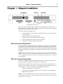
DS3-10/100 RIOP Installation Guide
Compatible Systems Corporation
4730 Walnut Street
Suite 102
Boulder, Colorado 80301
303-444-9532
800-356-0283
http://www.compatible.com
DS3-10/100 RIOP Installation Guide, Version 1.0
Copyright© 1999, Compatible Systems Corporation
All rights reserved. VSR, VSR-2, MicroRouter and CompatiView are trademarks of Compatible
Systems Corporation. Other trademarks are the property of their respective holders.
FCC Notice: This product has been certified to comply with the limits for a Class A computing device,
pursuant to Subpart J of Part 15 of FCC Rules. It is designed to provide reasonable protection against
radio or television communication interference in a commercial environment. Operation of this equipment in a residential area could cause interference with radio or television communication.
Table of Contents
Introduction to the DS3-10/100 RIOP
1
Chapter 1 - Network Installation
2
Ethernet Connection Requirements
DS3 Line Connection Requirements
Connecting the DS3-10/100 to the Ethernet
Connecting the DS3-10/100 to a DS3 Line
Connecting a Management Console
Powering Up the Router
2
2
3
3
3
3
Chapter 2 - Quickstart Configuration
4
ETHERNET INTERFACE CONFIGURATION
IP Protocol
5
5
5
5
5
5
5
5
5
6
6
6
6
6
6
6
6
7
7
7
7
7
7
7
7
7
7
7
8
8
8
8
8
8
8
Required for IP
Suggested for IP
IPX Protocol
Required for IPX
Suggested for IPX
AppleTalk Protocol
Required for AppleTalk
Suggested for AppleTalk
DECnet Protocol
Required for DECnet
Suggested for DECnet
WAN INTERFACE CONFIGURATION
Internal DS3 CSU/DSU Physical Communications Settings
Required for Dedicated Line Operation
Suggested for Dedicated Line Operation
PPP Configuration
Internal DS3 CSU/DSU Link Configuration
Required for Dedicated Line Operation
Suggested for Dedicated Line Operation
IP Protocol
Required for IP
Suggested for IP
IPX Protocol
Required for IPX
AppleTalk Protocol
Required for AppleTalk
DECnet Protocol
Required for DECnet
Frame Relay Configuration
Internal DS3 CSU/DSU Link Configuration
Required for Dedicated Line Operation
Suggested for Dedicated Line Operation
Frame Relay DLCI Mappings
i
Table of Contents
IP Protocol
SMDS Addressing
SAVING A CONFIGURATION FILE TO FLASH ROM
9
9
9
9
9
9
10
10
10
10
10
10
11
11
11
11
11
Chapter 3 - Shipping Defaults
12
Required for IP Numbered Interface
Required for IP Unnumbered Interface
Suggested for IP
IPX Protocol
Required for IPX
Suggested for IPX
AppleTalk Protocol
Required for AppleTalk
Suggested for AppleTalk
DECnet Protocol
Required for DECnet
SMDS Configuration
Link Configuration
Suggested for Dedicated/Leased Line Operation
Ethernet Interface
IP Defaults
IPX Defaults
AppleTalk Defaults
DECnet Defaults
DS3 CSU/DSU Defaults
12
12
12
12
12
12
12
12
12
12
12
Chapter 4 - LED Patterns
13
IP Routing Defaults
IPX Routing Defaults
AppleTalk Routing Defaults
DECnet Defaults
WAN Interface
Over Temp
Sys Ready
General Indicators
Ethernet Traffic Indicators
DS3 Indicators
Ethernet Connection Indicators
DS3 Connection Indicators
13
13
13
14
14
14
14
ii
Introduction to the DS3-10/100 RIOP
1
Introduction to the DS3-10/100 RIOP
The DS3-10/100 Routing Input/Output Processor (RIOP), as part of the VSR multigigabit
switching router, allows you to connect a local Ethernet and remote corporate network. The
DS3 interface has a data capacity of 44.736 Mbps, while the Ethernet interface can operate at
either 10 Mbps or 100 Mbps.
This section of the manual contains information specific to the DS3-10/100 RIOP. It is divided
into the following sections:
Chapter 1: Network Installation
Here you will find step-by-step instructions on how to physically install the DS3-10/100 and
connect it to your network.
Chapter 2: Quickstart Configuration
The Quickstart section provides a basic list of parameters that must be entered into the
DS3-10/100 for proper operation.
Chapter 3: Shipping Defaults
This section of the manual lists factory defaults for each interface.
Chapter 4: LED Patterns
This section of the manual describes the LED indicators for the DS3-10/100.
Chapter 1 - Network Installation
2
Chapter 1 - Network Installation
DS3-10/100 RIOP Front Panel
This section of the manual will help you install the DS3-10/100 RIOP to connect a local
Ethernet and remote corporate network. These connections can be made to other Compatible
Systems routers or routers from other vendors.
In summary, the steps for installation are:
1.
After mounting the router or placing on a desktop, make sure it is not connected to
any power source.
2.
Connect the router to the Ethernet network.
3.
Connect the router to the DS3 transmission equipment.
4.
Connect a management console to the router (optional).
5.
Plug in the power cable and power up the router.
Ethernet Connection Requirements
The 10/100 Ethernet interface directly supports 100BaseTx or 10BaseT twisted-pair Ethernet.
To connect the router’s Ethernet interface to twisted-pair Ethernet cabling, you will need an
unshielded twisted-pair station cable that is connected to a 10BaseT-compatible twisted-pair
hub (for a transmit speed of 10 Mbps) or a 100Mbps Fast Ethernet hub (for a transmit speed of
100 Mbps).
v Note: Ethernet cables and cable connectors are not supplied with the DS3-10/100 RIOP
product. Category 5 cabling is required for 100 BaseT operation. Please contact your reseller
or your Compatible Systems representative for information on obtaining the correct Ethernet
cabling supplies.
DS3 Line Connection Requirements
The DS3-10/100 RIOP includes an integrated DS3 CSU/DSU. To connect this interface to
your DS3 transmission equipment, you will need two coaxial cables.
These cables require special tools to be built correctly. You can use your approved cable
supplier or you can contact your reseller or your Compatible Systems representative for a list
of cable suppliers. To have a cable built, use the following specifications:
•
Cable Type: AT&T type 734A or equivalent
•
Connector Type: AMP Incorporated 413589-7 or equivalent (75 Ohm BNC plug)
•
Maximum Length: 900 feet
v Note: The DS3-10/100 RIOP includes loopback features which can be used to check the
functionality of your DS3 line. Before attempting to route network traffic, use these features to
check the line’s basic integrity.
Chapter 1 - Network Installation
3
Connecting the DS3-10/100 to the Ethernet
If your twisted-pair hub is already in place, you can connect the router to an active network
without interrupting network activity. Before connecting the router to twisted-pair cabling you
need an unshielded twisted-pair cable that is already connected to your 10BaseT-compatible or
100BaseTx-compatible twisted-pair hub.
To connect the router to the twisted-pair network, simply plug the twisted-pair cable into the
RJ-45 Ethernet connector on the front of the unit.
Connecting the DS3-10/100 to a DS3 Line
The DS3 line port consists of two 75 ohm BNC female coaxial connectors labeled DS3 XMT
and DS3 RCV. To connect the router to the DS3 line, you need two AT&T type 734A or equivalent coaxial cables.
Install one cable between the router’s DS3 XMT connector and the RCV connector on the DS3
transmission equipment. Install the other cable between the router’s DS3 RCV connector and
the XMT connector on the DS3 transmission equipment.
Connecting a Management Console
If you wish to connect an out-of-band management console, use the supplied cable and connect
to the Console interface on the DS3-10/100 RIOP. You can use a dumb terminal or a computer
equipped with VT100 terminal emulation.
The default settings for the Console interface are VT100 terminal emulation, 9600 bps, 8 bits,
no parity, 1 stop bit and no Flow Control.
v Note: The DS3-10/100 RIOP also has an AUX interface. This is a modem connection which
should only be used in consultation with Compatible Systems Technical Support staff, who will
provide instruction on its use.
Powering Up the Router
Connect the supplied power cord to the front of the VSR and set the power switch to “On.” At
power-up, the router will take approximately one minute to become visible to CompatiView.
v Note: If you want to use telnet as a management method, you must first configure an IP
address into the router with either an out-of-band console, CompatiView, or with a reconfigured IP host or workstation on the same Ethernet segment as the router. See the appropriate
VSR chassis section of the manual for more information on Command Line Management.
Chapter 2 - Quickstart Configuration
4
Chapter 2 - Quickstart Configuration
This chapter briefly discusses the major parameters that must be set in order to use the
DS3-10/100 RIOP as part of your VSR multigigabit switching router.
Detailed information on the meaning of the router’s parameters is provided in the CompatiView Management Software Reference Guide and the Text-Based Configuration and
Command Line Management Reference Guide. You should use this list as a starting point to
look up more specific information in the other documents.
If you need more general information on IP, IPX, AppleTalk or wide area protocols, see the
Appendices in the CompatiView Management Software Reference Guide.
There are a number of parameter settings which are optional, in the sense that they are not
required for all installations. These settings are not covered in this chapter.
In this chapter:
CV = CompatiView
TB = Text-Based Configuration
In order to successfully connect to an Internet Service Provider (ISP), you must use router
configuration parameters which will be provided by the technical staff of the ISP. These
parameters must include all IP addresses, WAN settings and any applicable authorization
routines. Please check with your ISP before configuring or changing the configuration of your
DS3-10/100 RIOP.
v Note: This guide does not include information on setting up packet filters for using the
router as a Firewall. See the CompatiView Management Software Reference Guide or
Text-Based Configuration and Command Line Management Reference Guide regarding IP
packet filters for more information.
Chapter 2 - Quickstart Configuration
5
Ethernet Interface Configuration
Ethernet interfaces are considerably easier to set up than WAN interfaces since there are fewer
choices that need to be made regarding communications protocols and parameters. We recommend that you begin by configuring any Ethernet interface parameters before proceeding to
configure WAN interface parameters.
IP Protocol
Required for IP
These parameters set the basic address characteristics of the interface. They provide enough
information for another IP node to find the interface (such as a telnet client), but not enough
information for routing to take place.
•
IP address
•
IP subnet mask
•
IP broadcast address
CV: Use the TCP/IP Routing: Ethernet Dialog Box to set these parameters.
TB: Use the configure command and the IPAddress, SubnetMask, and IPBroadcast
keywords in the IP Ethernet 0 section.
Suggested for IP
These parameters help supply information about the segment that the interface is connected to.
With this information, routing can take place.
•
Set IP RIP 1, IP RIP 2 or OSPF (Open Shortest Path First)
•
IP static routes
CV: Use the TCP/IP Routing: Ethernet Dialog Box to set RIP, and the IP Static Routing
Dialog Box (under Global/IP Static Routes) to set static routes. OSPF can only be configured
using text-based configuration.
TB: Use configure and set either the RIPVersion keyword or the OSPFEnabled keyword for
the IP Ethernet 0 section. Use edit config and add static routes in the IP Static section.
IPX Protocol
Required for IPX
Generally, there are no required changes from the shipping Ethernet configuration for IPX.
The Ethernet interface will autoconfigure to use the two most common IPX frame types, and
will autoadapt to conditions on the Ethernet.
Suggested for IPX
You may want to set your own network numbers, rather than using the autoconfigured values.
You may also want to turn off unused frame types.
CV: Use the IPX Routing: Ethernet Dialog Box.
TB: Use configure and set keywords in the IPX Ethernet 0 section.
AppleTalk Protocol
Required for AppleTalk
Generally, there are no required changes from the shipping Ethernet configuration for AppleTalk. The Ethernet interface will autoconfigure to use AppleTalk Phase 2, and will autoadapt
to conditions on the Ethernet.
Chapter 2 - Quickstart Configuration
6
Suggested for AppleTalk
You may want to set your own network numbers, rather than using the autoconfigured values.
You may also want to use more meaningful zone names.
CV: Use the AppleTalk Routing: Ethernet Dialog Box.
TB: Use configure and set keywords in the AppleTalk Phase 2 Ethernet 0 section.
DECnet Protocol
Required for DECnet
The router’s shipping configuration does not have DECnet turned on. In order to be used,
DECnet must be turned on both globally and for a particular port.
•
Set DECnet on (globally, and for this port)
•
Set DECnet area
•
Set DECnet node
CV: Use the DECnet Routing Dialog Box (under Global/DECnet Routing) and the DECnet:
Ethernet Dialog Box.
TB: Use configure and set the Mode keyword in the DECnet Ethernet 0 section. Use
configure and set the Enabled, Area, and Node keywords in the DECnet Global section.
v Note: Setting DECnet on for any port with the command line also sets DECnet on globally.
In CompatiView you must set a global parameter and a port-specific parameter.
Suggested for DECnet
Setting the parameters above should be adequate for most installations.
WAN Interface Configuration
In order to use the WAN interface, you may want to set some physical parameters. Then set up
the link and protocol parameters.
Internal DS3 CSU/DSU Physical Communications Settings
Required for Dedicated Line Operation
No changes from the default values are required for standard operation over a DS3 line. The
default values are listed in Chapter 3.
Suggested for Dedicated Line Operation
Changing to a different Line Build Out may be required. These parameters can only be set
using the command line interface.
TB: Use configure and the DS3 Interface WAN 0 section.
Chapter 2 - Quickstart Configuration
7
PPP Configuration
This section covers the settings required for PPP (point-to-point) protocol operation of the DS3
WAN interface.
Internal DS3 CSU/DSU Link Configuration
Required for Dedicated Line Operation
This is the only mode of operation supported via the built-in DS3 CSU/DSU.
•
Set Dedicated connection
•
Set PPP connection
CV: Use the Link Configuration: WAN Dialog Box.
TB: Use configure and then set the Mode and ConnectMode keywords in the Link Config
WAN 0 section.
Suggested for Dedicated Line Operation
Dedicated line operation generally does not require additional parameters for operation.
IP Protocol
Required for IP
WAN interfaces which are set for PPP operation do not generally use an IP address. They are
set to act as an “unnumbered interface.” In this mode of operation, there are no required
settings.
Suggested for IP
These parameters help supply information about the segment that the interface is connected to.
With this information, routing can take place.
•
Set IP RIP 1, IP RIP 2, OSPF (Open Shortest Path First) or BGP (Border Gateway
Protocol)
•
Set IP static routes
CV: Use the TCP/IP Routing: WAN Dialog Box to set RIP, and the IP Static Routing Dialog
Box (under Global/IP Static Routes) to set static routes. OSPF and BGP can only be configured using text-based configuration.
TB: Use configure and set either the RIPVersion keyword or the OSPFEnabled keyword in
the IP WAN 0 section. Add static routes and a default router in the IP Static section.
v Note: Due to the complexity of BGP, configuration parameters for BGP are not given in this
Quickstart. For help with BGP configuration parameters, and other configuration questions,
refer to the Tech Support pages on the Compatible Systems Web site at:
http://www.compatible.com/.
IPX Protocol
Required for IPX
WAN interfaces which are set for PPP operation do not generally use an IPX address. They are
set to act as an “unnumbered interface.” In this mode of operation, there are no required
settings.
AppleTalk Protocol
Required for AppleTalk
WAN interfaces which are set for PPP operation do not generally use an AppleTalk address.
They are set to act as an “unnumbered interface.” In this mode of operation, there are no
required settings.
Chapter 2 - Quickstart Configuration
8
DECnet Protocol
Required for DECnet
The router’s shipping configuration does not have DECnet turned on. In order to be used,
DECnet must be turned on both globally and for a particular port.
•
Set DECnet on (globally, and for a port)
•
Set DECnet area
•
Set DECnet node
CV: Use the DECnet Routing Dialog Box (under Global/DECnet Routing) and the DECnet:
WAN Dialog Box.
TB: Use configure and set the Mode keyword in the DECnet WAN 0 section.
v Note: Setting DECnet on for any port with the command line also sets DECnet on globally.
In CompatiView you must set a global parameter and a port-specific parameter.
Frame Relay Configuration
This section covers the settings required for Frame Relay operation of the DS3 WAN interface.
Internal DS3 CSU/DSU Link Configuration
Required for Dedicated Line Operation
This is the only mode of operation supported via the built-in DS3 CSU/DSU.
•
Set Dedicated connection
•
Set Frame Relay connection
CV: Use the Link Configuration: WAN Dialog Box.
TB: Use configure and then set the Mode and ConnectMode keywords in the Link Config
WAN 0 section.
Suggested for Dedicated Line Operation
Dedicated line operation generally does not require additional parameters for operation.
Frame Relay DLCI Mappings
If you are connecting to another Compatible Systems router, this information is not required
for Frame Relay operation. Compatible Systems uses IARP (Inverse Address Resolution
Protocol) to dynamically generate this information. To connect to other vendors’ routers
which do not support IARP, you must provide DLCI-to-protocol mapping information.
v Note: Many Internet Service Providers (ISP’s) do not support IARP as a default. If your
WAN interface will be connected to an ISP via Frame Relay, check with your ISP technical
staff on whether or not you must manually enter DLCI information.
CV: Use the DLCI Mapping Database window.
TB: Use configure and set the DLCI keyword in the Frame Relay WAN 0 section.
Chapter 2 - Quickstart Configuration
9
IP Protocol
There are two ways to set up Frame Relay. One is to set the WAN interface as a “numbered
interface.” This means that the interface (and thus the Frame Relay network) will have an IP
address, subnet mask, etc. The other is to set it as an unnumbered interface and specify that the
link is point-to-point Frame Relay and set the local DLCI. Unnumbered Frame Relay can only
be configured using text-based configuration. Instructions are provided for both options.
Required for IP Numbered Interface
•
IP numbered interface
•
IP address
•
IP subnet mask
•
IP broadcast address
CV: Use the TCP/IP Routing: WAN Dialog Box.
TB: Use the configure command and the Numbered, IPAddress, SubnetMask, and
IPBroadcast keywords in the IP WAN 0 section.
Required for IP Unnumbered Interface
•
IP unnumbered interface
•
Point-to-Point Frame Relay
•
Local DLCI
TB: Use the configure command and the Numbered, PointToPointFrame, and InterfaceDLCI keywords in the IP WAN 0 section.
Suggested for IP
These parameters help supply information about the segment that the interface is connected to.
With this information, routing can take place.
•
Set IP RIP 1, IP RIP 2, OSPF (Open Shortest Path First) or BGP (Border Gateway
Protocol)
•
IP static routes
CV: Use the TCP/IP Routing: WAN Dialog Box to set RIP, and the IP Static Routing Dialog
Box (under Global/IP Static Routes) to set static routes. OSPF and BGP can only be configured using text-based configuration.
TB: Use configure and set either the RIPVersion keyword or the OSPFEnabled keyword in
the IP WAN 0 section. Add static routes and a default router using the edit config IP Static
command.
v Note: Due to the complexity of BGP, configuration parameters for BGP are not given in this
Quickstart. For help with BGP configuration parameters, and other configuration questions,
refer to theTech Support pages on the Compatible Systems Web site at:
http://www.compatible.com/.
IPX Protocol
Required for IPX
Frame Relay operation requires that the WAN interface be set as a “numbered interface.” This
means that the interface (and thus the Frame Relay network) must have an IPX network
number.
•
IPX numbered interface
•
IPX network number
CV: Use the IPX Routing: WAN Dialog Box.
Chapter 2 - Quickstart Configuration
10
TB: Use configure and set the Numbered and Net keywords in the IPX WAN 0 section.
Suggested for IPX
The settings above are all that is generally required for IPX operation over Frame Relay.
AppleTalk Protocol
Required for AppleTalk
Frame Relay operation requires that the WAN interface be set as a “numbered interface.” This
means that the interface (and thus the Frame Relay network) must have an AppleTalk network
number and the interface must have an AppleTalk node number.
•
AppleTalk numbered interface
•
AppleTalk network number
•
AppleTalk node number
•
AppleTalk zone name
CV: Use the AppleTalk Routing: WAN Dialog Box.
TB: Use configure and set the Numbered, NetLower, and DefZone keywords in the AppleTalk WAN 0 section.
Suggested for AppleTalk
The settings above are all that is generally required for AppleTalk operation over Frame Relay.
DECnet Protocol
Required for DECnet
In order to be used, DECnet must be turned on both globally and for a particular port.
WAN interfaces which are set for Frame Relay operation do not need any additional parameters set in order to function.
•
Set DECnet on (globally, and for this port)
CV: Use the DECnet Routing Dialog Box (under Global/DECnet Routing) and the DECnet:
WAN Dialog Box.
TB: Use configure and set the Mode keyword in the DECnet WAN 0 section.
v Note: Setting DECnet on for any port with the command line also sets DECnet on globally.
In CompatiView you must set a global parameter and a port-specific parameter.
Chapter 2 - Quickstart Configuration
11
SMDS Configuration
This section covers the settings required for SMDS (Switched Multi-megabit Data Service)
operation of the DS3 WAN interface (IP only). SMDS is a connectionless, packet-switched
service that offers LAN-to-LAN connectivity across a wide area at up to 1.544 Mbps. SMDS
addresses and other parameters can only be set using text-based configuration.
v Note: The IP protocol settings and the physical communication settings are the same as they
would be for Frame Relay operation. The only parameters which should be set differently for
SMDS are the Link Configuration and the SMDS addressing section.
Link Configuration
SMDS is presently supported in the DS3-10/100 RIOP only via synchronous dedicated line
operation.
•
Set Dedicated connection
•
Set SMDS connection
TB: Use configure to set the Mode and ConnectMode keywords in the Link Config WAN 0
section.
Suggested for Dedicated/Leased Line Operation
Dedicated line operation generally does not require additional parameters for operation.
SMDS Addressing
Many of these parameters will be given to you by your service provider.
TB: Use configure and set the StationAddress, IPMulticast and PollingFrequency
keywords in the SMDS WAN 0 section.
Saving a Configuration File to Flash ROM
Once a configuration is complete, you can save it to the router’s Flash ROM. Until saved, all
changes are made in a separate buffer and the actual router interfaces continue to run as before
the changes were made.
CV: Use the Save to/Device option from the File menu.
TB: Use the save command.
Chapter 3 - Shipping Defaults
Chapter 3 - Shipping Defaults
Ethernet Interface
IP Routing Defaults
•
On
•
Address: 198.41.12.1
•
Subnet Mask: 255.255.255.0
•
Broadcast Address: 198.41.12.255
•
IP RIP off
IPX Routing Defaults
•
802.3 on, autoseeding
•
802.2 on, autoseeding
•
Type II on, nonseeding
•
802.2 SNAP on, nonseeding
AppleTalk Routing Defaults
•
Phase 1 off
•
Phase 2 on, autoseeding
DECnet Defaults
•
Off
WAN Interface
IP Defaults
•
On
•
Unnumbered interface
•
RIP off
•
Van Jacobson compression off
IPX Defaults
•
On
•
Unnumbered interface
AppleTalk Defaults
•
On
•
Unnumbered interface
DECnet Defaults
•
Off
DS3 CSU/DSU Defaults
•
PPP
•
Internal clocking
•
16 bit CRC
12
Chapter 4 - LED Patterns
13
Chapter 4 - LED Patterns
Some of the LEDs on the front of the VSR multigigabit switching router serve dual functions.
In addition to indicating certain router-wide operating conditions and they may also display
port-specific information.
v Note: Any continuous flashing pattern not noted in this chapter may be caused by a hardware failure. Please call Compatible Systems Technical Support if your router shows a hardware failure.
Router LED Patterns
The following LEDs and light patterns provide information about the VSR’s physical state and
operating conditions.
Over Temp
The router is above the proper operating temperature. The filter needs changing. See the
appropriate VSR chassis section of the manual for instructions.
Sys Ready
The router booted properly without detecting any failures.
General Indicators
Ethernet Lights
DS3 Lights
Indication
5 flashing
1 flashing
Router stacks starting up.
3&4 flashing
2&3 flashing
No OS loaded. Running from ROM.
1&4 flashing
2&5 flashing
Erasing OS in Flash ROM.
5 flashing
1,2&3 flashing
Erasing config in Flash ROM.
1 - 5 scanning
5 - 1 scanning
Flash ROM erase due to switch setting five or six
is complete. Set switch to zero and cycle power.
Chapter 4 - LED Patterns
14
DS3-10/100 RIOP LED Patterns
The following LEDs and light patterns provide information about the DS3-10/100 RIOP interfaces.
Ethernet Traffic Indicators
Scan from 1 to 3: Ethernet transmit packet
Scan from 5 to 3: Ethernet receive packet
DS3 Indicators
Scan from 1 to 3: WAN transmit packet
Scan from 5 to 3: WAN receive packet
Ethernet Connection Indicators
Link: The Link light indicates that there is a good connection to the hub.
Activity: The Activity light indicates that there is activity across the link.
100: The 100 light indicates that the interface is operating at 100 Mbps.
DS3 Connection Indicators
TX: WAN transmit packet
RX: WAN receive packet
Link: The Link light indicates that the interface is receiving signal from the upstream terminal.