1
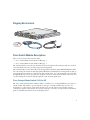
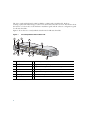
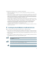
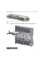
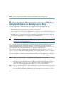
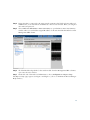
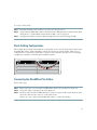
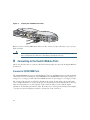
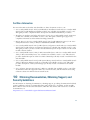
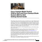
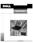
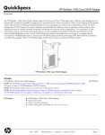
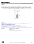
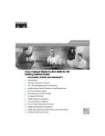
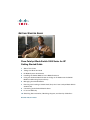
GETTING STARTED GUIDE
Cisco Catalyst Blade Switch 3000 Series for HP
Getting Started Guide
1
About This Guide
2
Taking Out What You Need
3
HP Blade System Architecture
4
Installing the Switch Module in the Blade Enclosure
5
Using the Onboard Administrator to Assign an IP Address to the Switch
Module and Running Express Setup
6
Managing the Switch Module
7
Planning and Creating a Switch Stack (Only the Cisco Catalyst Blade Switch
3120 for HP)
8
Connecting to the Switch Module Ports
9
In Case of Difficulty
10 Obtaining Documentation, Obtaining Support, and Security Guidelines
November 2007, OL-14257-01
1 About This Guide
This guide provides instructions on how to install your Cisco Catalyst Blade Switch 3120 for HP or
Cisco Catalyst Blade Switch 3020 for HP— referred to as the switch module—in the HP c-Class
BladeSystem and how to set up and configure your switch module. The HP c-Class BladeSystem—
referred to as the blade enclosure—supports up to eight Ethernet switch modules, which are installed
in the interconnect bays of the blade enclosure.
This guide also covers management options and troubleshooting help for the switch module.
For details on the numbers, types, and the location of the blade enclosure bays, for additional
information on the blade enclosure system, and for detailed port mapping information, see the
HP BladeSystem enclosure installation poster or the HP BladeSystem enclosure setup and installation
guide at http://www.hp.com/go/bladesystem/documentation.
For additional installation and configuration information about the switch module, see the Cisco
Catalyst Blade Switch 3000 Series for HP documentation on Cisco.com. For system requirements,
important notes, limitations, open and resolved caveats, and last-minute documentation updates about
the switch module, see the release notes, also on Cisco.com.
When you use the online publications, refer to the documents that match the Cisco IOS software
version that is running on the switch module. See the “Obtaining Documentation” section on
page 1-24 for more information about the switch module publications.
For translations of the warnings that appear in this publication and all safety and handling warnings
for this product, see the Regulatory Compliance and Safety Information for the Cisco Catalyst Blade
Switch 3000 Series for HP that accompanies this guide.
Before you continue with the installation, read the release notes for the blade enclosure. The release
notes are available on the HP support website at www.support.hp.com.
For warranty information about the switch module, see the Hardware Warranty Terms for the Cisco
Catalyst Blade Switch 3000 Series for HP on the documentation CD that ships with your switch
module.
2 Taking Out What You Need
Follow these steps:
1. Unpack and remove the switch module and the accessory kit from the shipping box.
2. Return the packing material to the shipping container, and save it for future use.
3. Verify that you have received the items shown on page 3. If any item is missing or damaged,
contact your Cisco representative or reseller for instructions.
If the switch modules are ordered with the blade enclosure, they are already installed. The unpacking
procedure for the switch module applies only if you order one separately. See the blade enclosure
documentation for the unpacking procedure for the HP equipment.
2
Shipping Box Contents
SYST
S-MODE
S-MSTR
S-MMBR
UID
19-20
MODE
23x
CONSOL
E
SFP19-2
0
21-22
STK A
SFP 21-2
2
24x
STK B
26x WS-CBS31
Do
cu
m
CD enta
tio
n
250286
20G-S
Cisco Switch Module Descriptions
These sections describe the switch modules:
• Cisco Catalyst Blade Switch 3120 for HP, page 3
• Cisco Catalyst Blade Switch 3020 for HP, page 5
The switch module is powered from the blade enclosure backplane. The switch module does not have
a fan. The blade enclosure provides temperature management.
The switch module connects internally to the management module through 100BASE-T Ethernet links.
You can manage the switch modules through the HP Onboard Administrator management module on
a management network that is isolated from other switch traffic. You can manage the switch module
through the RS-232 console port that uses an RJ-45 connector in the switch module front-panel. You
can also manage the switch module through any of the external uplink ports.
Cisco Catalyst Blade Switch 3120 for HP
The Cisco Catalyst Blade Switch 3120 for HP is a stackable, 25 to 27 Gigabit Ethernet port, Layer 3
switch module. The number of ports depends on the type of module installed in ports 19 to 22.
See Table 1 for a description of the switch module ports. See the release notes and the software
configuration guide for information about supported Layer 3 features. See the hardware installation
guide for detailed information about stacking the switch.
3
The Cisco Catalyst Blade Switch 3120 for HP has a 3120G and a 3120X model. Both are
stacking-capable. The initial setup procedure for both models is the same. For more information about
the features of each model, see the hardware installation guide and the software configuration guide
for the switch module.
Figure 1 shows the Cisco Catalyst Blade Switch 3120 for HP switch module.
Figure 1
The Catalyst Blade Switch 3120 for HP
7
1
8
3
2
9
UID
19-20
MODE
23x
CONS
OLE
SFP19-2
0
4
21-22
STK A
5
6
SFP 21
10
-22
24x
11
12
STK B
26x WS-CBS3
250154
SYST
S-MODE
S-MSTR
S-MMBR
120G-S
13
1
Switch module
1
8
LEDs for ports 19 and 20
Gigabit Ethernet uplink ports 23 to 26
2
UID LED
9
3
Health LEDs
10 Gigabit Ethernet ports 19 and 20 or 10-Gigabit Ethernet slot 1
4
System status LEDs
11 LEDs for ports 21 and 22
5
Mode button
12 Gigabit Ethernet ports 21 and 22 or 10-Gigabit Ethernet slot 2
6
Console port
13 StackWise Plus ports
7
Release latch
1. UID: unit identifier.
4
Table 1 describes the Cisco Catalyst Blade Switch 3120 for HP switch module ports. Each external
port has an associated LED.
Table 1
Cisco Catalyst Blade Switch 3120 for HP Port Descriptions
Port
Description
Ports 1 to 16
Internal Gigabit Ethernet 1000BASE-X downlink ports that connect to the
blade enclosure.
Ports 17 to 18
Internal cross-connection ports that you can use to connect to a second
switch in the blade enclosure through a backplane connector. You can
configure these ports by using the Cisco IOS CLI. However, if the blade
switches are stacked, these ports are disabled.
Ports 19 to 22
10-Gigabit Ethernet module slots for use with the Cisco TwinGig Converter
Modules and Cisco X2 transceiver modules.
Ports 23 to 26
External 10/100/1000BASE-T copper Gigabit Ethernet uplink ports that
support auto-MDIX and autonegotiation.
Internal 100BASE-T
Ethernet port
The Ethernet management port (Fa0) is used only for switch module
management traffic, not for data traffic. It is connected to the
Onboard Administrator through the blade enclosure backplane connector.
Traffic to and from this port is isolated from the switch ports. This port
only supports autonegotiation with 100 Mb/s and full-duplex mode.
StackWise Plus ports
Stacking cable ports.
Console port
Switch module management port (RJ-45 connector).
Cisco Catalyst Blade Switch 3020 for HP
The Cisco Catalyst Blade Switch 3020 for HP is a 24-Gigabit Ethernet port, Layer 2+ switch module.
Sixteen of the Gigabit Ethernet ports are internal 1000BASE-X downlink ports that connect to the
blade enclosure. The other eight Gigabit Ethernet ports are external uplink ports that provide
connections to other switches or routers. Uplink ports operate at 10/100/1000 M/ps if used as
copper-based ports and operate at 1000 M/ps if small form-factor pluggable (SFP) fiber-optic modules
are installed. See Table 2 for more detailed descriptions of the switch module ports.
5
Figure 2 shows the Cisco Catalyst Blade Switch 3020 for HP switch module. Each external port has
an associated LED.
Figure 2
The Catalyst Blade Switch 3020 for HP
2
6
1
SYST
STAT
DLX
SPD
UID
MODE
WS-CB
S-3020
CONS
-HPQ
OLE
9
17
MEDIA
DETECT
SFP/R-
10
45 PORT
S 17-20
11
17x
17x 21
x
20
17
19
3
20
20x 24
x
23x
18x
153139
18
4 5
7 8
24x
1
Switch module
7
Health LED
2
Release latch
8
LEDs for SFP module ports 17 to 20
3
System status LEDs
9
SFP module ports 17 to 20
4
Mode button
10 LEDs for Gigabit Ethernet ports 17x to 24x
5
Console port
11 Gigabit Ethernet ports 17x to 24x
6
UID1
LED
1. UID: unit identifier.
6
Table 2 describes the switch module ports. Each external port has an associated LED.
Table 2
Cisco Catalyst Blade Switch 3020 for HP Port Descriptions
Port
Description
Ports 1 to 16
Internal Gigabit Ethernet 1000BASE-X downlink ports.
Ports 17 to 20 and
Ports 17x to 20x
Dual-purpose SFP module/RJ-45 copper Ethernet uplink ports. The SFP module
ports support only Cisco 1000BASE-SX fiber-optic modules.
By default, the switch module dynamically selects the interface type that first
links up. SFP modules have precedence if both SFP module and copper Ethernet
interface types are in link-up state. You can also specifically configure each port
for either copper Ethernet or SFP modules if you do not want to use
autodetection.
The copper Ethernet ports support automatic medium-dependent interface
crossover (auto-MDIX) and autonegotiation.
For information about configuring speed and duplex settings for a
dual-purpose uplink port, see the software configuration guide.
Ports 21x to 22x
External 10/100/1000BASE-T copper Gigabit Ethernet uplink ports that
support auto-MDIX and autonegotiation.
Ports 23x to 24x
Dual-purpose external/internal 10/100/1000BASE-T copper Gigabit Ethernet
uplink ports. These ports can be configured for internal 1000BASE-X
cross-connection with a corresponding switch module. When ports 23x and
24x are in external operation mode, they support auto-MDIX and
autonegotiation. The default is external operation mode.
Internal
100BASE-T
Ethernet port
The Ethernet management port (Fa0) is used only for switch module
management traffic, not for data traffic. It is connected to the Onboard
Administrator through the blade enclosure backplane connector.
Console port
Switch module management port (RJ-45 connector).
7
3 HP Blade System Architecture
Figure 3 shows the rear view of the blade enclosure, in which you install the switch module.
Figure 3
Rear View of the Blade Enclosure
1
2
3
4
5
6
7
8
9
10
11
153140
2
1
Blade enclosure rear view
7
Interconnect module bay 5
2
Blade enclosure fans
8
Interconnect module bay 6
3
Interconnect bay 1 with switch module installed 9
Interconnect module bay 7
4
Interconnect module bay 2
10 Interconnect module bay 8
5
Interconnect module bay 3
11 Onboard Administrator module
6
Interconnect module bay 4
8
Consider these prerequisites before you install the switch module:
• Fill any unoccupied interconnect bays or any unoccupied power module bays in the blade
enclosure with blanks.
• Identify the bays in which you will insert the switch modules. Plan to install the first switch module
in bay 1, the second in bay 2, and so on up to bay 8, if possible. The bay in which you choose to
install each switch module depends on whether mezzanine or Ethernet cards are installed in the
blade enclosure and how they are configured. See the blade enclosure documentation information
about installing and configuring the mezzanine or Ethernet cards.
The interconnect module bays are physically interconnected in pairs through the blade enclosure
backplane. That is, each of these pairs—bays 1 and 2, bays 3 and 4, bays 5 and 6, and bays 7 and
8—are interconnected. If you install two switch modules in one of the paired bays, they are
internally interconnected. You must configure the switch modules to logically enable the
interconnect ports, Gigabit Ethernet ports 23 and 24. See the switch module software
configuration guide for information on configuring these ports.
• See the HP c-Class documentation for information on the port mapping between blade enclosures
and the switch modules.
4 Installing the Switch Module in the Blade Enclosure
Before you install the switch module in the blade enclosure, consider these points:
• Review and become familiar with the safety guidelines in the Regulatory Compliance and Safety
Information for the Cisco Catalyst Blade Switch 3000 Series for HP that accompanies this guide.
• Review and become familiar with the safety guidelines in the HP BladeSystem enclosure setup and
installation guide.
• Review and become familiar with the temperature, power, and grounding requirements specified
in the HP BladeSystem enclosure setup and installation guide.
Warning
Only trained and qualified personnel should be allowed to install, replace, or service
this equipment. Statement 1030
Caution
To prevent electrostatic-discharge (ESD) damage when installing switch modules, follow
your normal board and component handling procedures.
Note
When you install a switch module, you do not need to power down the blade enclosure.
9
Follow these steps to install the switch module in the blade enclosure. The illustrations in this section
show the Cisco Catalyst Blade Switch 3020 for HP switch module. The instructions are the same for
the Cisco Catalyst Blade Switch 3120 for HP switch module.
Step 1
If you have not already done so, touch the static-protective package that contains the switch
module to an unpainted metal part of the blade enclosure for at least 2 seconds.
Step 2
Remove the switch module from its static-protective package.
Step 3
Remove the interconnect blank from the bay where you plan to install the switch module, if
one is present, and install the switch module. (See Figure 4.)
Figure 4
Removing the Interconnect Module Blank from the Blade Enclosure
153142
1
1
10
Lever for the interconnect module blank
Ensure that the release latch on the switch module is in the open position (perpendicular to
the module)
Step 4
:
SYST
STAT
DLX
SPD
UID
MODE
WS-CB
S-3020
CONS
-HPQ
OLE
17
MEDIA
DETECT
SFP/R-
45 PORT
S 17-20
17x
17x 21
x
20
17
19
20
20x 24
x
23x
18x
153141
18
24x
Slide the switch module into the bay until it stops. (See Figure 5.)
Step 5
Figure 5
Installing the Switch Module into the Blade Enclosure Interconnect Module Bay
1
SYST
STAT
DLX
SPD
MODE
CONS
WS-CBS-30
OLE
20-HP
Q
UID
17
MEDIA
DETECT
SFP/R-45
PORTS
17-20
17x
17x 21x
20
17
18
19
20
20x 24x
23x
18x
153143
24x
1
Switch module release latch
11
Step 6
Push the release latch on the front of the switch module to the closed position.
5 Using the Onboard Administrator to Assign an IP Address
to the Switch Module and Running Express Setup
For the switch module to obtain an IP address for the Fa0 interface through the Onboard
Administrator, these conditions must be met:
• The blade enclosure is powered on and connected to the network.
• Basic configuration of the Onboard Administrator is completed, and you have the username and
password for the Onboard Administrator.
• A DHCP server is configured on the network segment to which the blade enclosure is connected,
or the Onboard Administrator is configured to run as a DHCP server.
Note
See the Onboard Administrator user guide at
http://www.hp.com/go/bladesystem/documentation for more information about configuring
and using the Onboard Administrator.
After you install the switch module in the interconnect module bay, after approximately 2 minutes, the
switch module automatically obtains an IP address for its Fa0 interface through the Onboard
Administrator. This method of obtaining an IP address occurs if a DCHP server is configured on the
same network, or if the Onboard Administrator is configured as a DHCP server.
After you have installed the switch module (see the “HP Blade System Architecture” section on
page 8), it powers on. The switch module begins the power-on self-test (POST), a series of tests that
runs automatically to ensure that the switch module functions properly.
To set up and initially configure the switch module by using the Cisco IOS CLI, see the “Configuring
the Switch with the CLI-Based Setup Program” section in the hardware installation guide.
Step 1
Wait for the switch module to complete POST. This might take several minutes.
Step 2
Verify that POST has completed by confirming that the system status LEDs remain green.
If the switch module fails POST, the system LED turns amber. If the POST fails, see the “In
Case of Difficulty” section on page 26 to determine a course of action. POST errors are
usually fatal. Call Cisco Systems immediately if your switch module fails POST.
Step 3
Wait approximately 2 minutes for the switch module to get the software image from its flash
memory and begin autoinstallation.
If you already have the Onboard Administrator open through a browser window, go to Step 5.
12
Step 4
Using a PC that is connected to the same network segment as the blade enclosure Onboard
Administrator, access the Onboard Administrator in a browser window. Enter your assigned
user name and password.
Step 5
Choose Enclosure Information > Interconnect Bays to open the Interconnect Bay Summary
window where you can find the assigned IP address of the switch module Fa0 interface in the
Management URL column.
Step 6
Click the IP address hyperlink for the switch module from the Management URL column to
open a new browser window.
Step 7
On the left side of the Onboard Administrator, choose Configuration > Express Setup.
The Express Setup page appears (see Figure 6 and Figure 7). (Close or minimize the Device Manager
Help window.)
13
Figure 6
Express Setup Page for the Cisco Catalyst Blade Switch 3120 for HP
Figure 7
Express Setup Page for the Cisco Catalyst Blade Switch 3020 for HP
Step 8
14
Go to “Using Express Setup” to finish setting up the switch module.
Using Express Setup
Before you complete the setup program, obtain the default gateway IP address and the switch
password from your system administrator. Depending on whether you are running Express Setup on
a Cisco Catalyst Blade Switch 3120 for HP switch module or a Cisco Catalyst Blade Switch
3020 for HP switch module, you can configure these optional parameters through the Express Setup
program:
• Telnet access password
• Names of the SNMP read and write community strings if you are going to use a
network-management program like CiscoWorks.
• Host name, system contact, and system location
• System time, time zone, Daylight Savings Time enable
Follow these steps to finish setting up the switch module. The Onboard Administrator assigns an
IP address and a subnet mask to the management interface (VLAN ID) and to the Ethernet
management port.
Step 1
Enter this information in the Network Settings fields.
– In the Default Gateway field, enter the IP address for the default gateway (router).
– In the Switch Password field, enter your password. The password can be from 1 to 25
alphanumeric characters, can start with a number, is case sensitive, allows embedded spaces,
but does not allow spaces at the beginning or end.
In the Confirm Switch Password field, enter your password again.
You can enter the Optional Settings information now or enter it later by using the device manager
interface.
Note
The fields in the Express Setup page depend on the type of switch module. Not all fields are
available in the Cisco Catalyst Blade Switch 3020 for HP switch module Express Setup page.
Some of the settings are on the Advanced Settings tab for the Cisco Catalyst Blade Switch
3120 for HP switch module (see Figure 8).
15
Figure 8
Advanced Settings Tab
Step 2
In the Host Name field, enter a name for the switch module. The host name is limited to
31 characters; embedded spaces are not allowed.
Step 3
In the System Date and System Time fields, enter the current date and time, or use the down
arrows to select them.
Step 4
In the Time Zone field, use the down arrow to choose your time zone.
Step 5
Click Enable in the Daylight Savings Time field to enable this feature.
Step 6
In the Telnet Access field, click Enable if you are going to use Telnet to manage the switch
module by using the CLI. If you enable Telnet access, you must enter a Telnet password.
Note
If you plan to create a switch stack, enable Telnet access so that you can use the CLI
to set this switch to the highest priority. See the “Planning and Creating a Switch
Stack (Only the Cisco Catalyst Blade Switch 3120 for HP)” section on page 21 for
more information about creating a switch stack.
Step 7
In the Telnet Password field, enter a password. The Telnet password can be from 1 to 25
alphanumeric characters, is case sensitive, allows embedded spaces, but does not allow spaces
at the beginning or end. In the Confirm Telnet Password field, re-enter the Telnet password.
Step 8
In the SNMP field, click Enable to enable Simple Network Management Protocol (SNMP).
Enable SNMP only if you plan to manage switches by using CiscoWorks 2000 or another
SNMP-based network-management system.
16
Step 9
If you enable SNMP, you must enter a community string in the SNMP Read Community field,
the SNMP Write Community field, or both. SNMP community strings authenticate access to
MIB objects. Embedded spaces are not allowed in SNMP community strings. When you set
the SNMP read community, you can access SNMP information, but you cannot modify it.
When you set the SNMP write community, you can both access and modify SNMP
information.
Step 10 In the System Contact field, enter the name of the person who is responsible for the switch
module. In the System Location field, enter the wiring closet, floor, or building where the
switch module is located.
Step 11 Depending on which software license you choose, you can enable IPv6 in the IPv6 Settings
area.
– Click Enable IPv6 to enable it.
– In the Interface column, choose the interface for which you want to set an IPv6 address and
complete the other fields in this table.
Step 12 Click Submit to save your settings, or click Cancel to clear your settings.
You can close this window. If you need to rerun Express Setup, see the “Resetting the Switch
Module” section on page 26.
To install additional switch modules, repeat the steps in the “Installing the Switch Module in the Blade
Enclosure” section on page 9 through the “Using the Onboard Administrator to Assign an IP Address
to the Switch Module and Running Express Setup” section on page 12.
Setting the Installed Switch to be the Stack Master (Only Cisco
Catalyst Blade Switch 3120 for HP Switches)
If you plan to create a switch stack, we recommend that you set the switch module that you first
configured as the stack master. To do this, you must assign the highest priority value to this switch
module. To assign a priority value after you have installed and initially configured the first switch
module, follow these steps:
Step 1
Choose Maintenance > Telnet on the left side of the Onboard Administrator window to
launch a Telnet session.
Step 2
Enter enable.
Step 3
Enter configure terminal.
Step 4
Enter switch 1 priority 15.
Step 5
At the prompt, press Return.
17
Step 6
Enter end.
Step 7
Enter copy running-configuration startup-configuration to save this setting.
Step 8
At the prompt, press Return.
Step 9
To verify that this switch is set as the stack master, enter the show switch user EXEC
command.
For more information about creating switch stacks, see the “Planning and Creating a Switch Stack
(Only the Cisco Catalyst Blade Switch 3120 for HP)” section on page 21.
6 Managing the Switch Module
After you complete Express Setup and install the switch module in your network, use the device
manager or other management options described in this section for further configuration.
Using the Device Manager
The simplest way to manage the switch module is by using the device manager that is in the switch
module memory. This is a web interface that offers quick configuration and monitoring. You can
access the device manager from anywhere in your network through a web browser.
Follow these steps:
Step 1
Launch a web browser on your PC or workstation.
Step 2
Enter the switch module IP address in the web browser, and press Enter. The device manager
page appears (see Figure 10 and Figure 9).
18
Figure 9
Device Manager Page for the Cisco Catalyst Blade Switch 3120 for HP
19
Figure 10
Device Manager Page for the Cisco Catalyst Blade Switch 3020 for HP
Step 3
Use the device manager to perform basic switch module configuration and monitoring. See the
device manager online help for more information.
Step 4
For more advanced configuration, download and run the Cisco Network Assistant, which is
described in the next section.
Using the Command-Line Interface
You can enter Cisco IOS commands and parameters through the CLI. Access the CLI either by
connecting your PC directly to the switch module console port or through a Telnet session from a
remote PC or workstation.
Follow these steps:
Step 1
Connect the supplied RJ-45-to DB-9 adapter cable to the standard 9-pin serial port on the PC.
Connect the other end of the cable to the console port on the switch module.
Step 2
Start a terminal-emulation program on the PC.
20
Step 3
Configure the PC terminal emulation software for:
– 9600 baud
– 8 data bits
– No parity
– 1 stop bit
– No flow control
Step 4
Use the CLI to enter commands to configure the switch module. See the software
configuration guide and the command reference for more information.
Using the Onboard Administrator CLI
See the HP BladeSystem enclosure setup and installation guide at
http://www.hp.com/go/bladesystem/documentation for information on how to use the Onboard
Administration CLI.
Other Management Options
You can use SNMP management applications such as CiscoWorks Small Network Management
Solution (SNMS) to configure and manage the switch module. You also can manage it from an
SNMP-compatible workstation that is running platforms such as HP OpenView or SunNet Manager.
The Cisco IE2100 Series Configuration Registrar is a network management device that works with
embedded Cisco Networking Services (CNS) agents in the switch module software. You can use
IE2100 to automate initial configurations and configuration updates on the switch module.
See the “Accessing Help Online” section on page 26 for a list of supporting documentation.
7 Planning and Creating a Switch Stack (Only the Cisco
Catalyst Blade Switch 3120 for HP)
A switch stack is a set of up to nine stacking-capable switch modules that are connected through their
StackWise Plus ports. One of the switches controls the operation of the stack and is called the stack
master. The stack master and the other switches in the stack are stack members. Layer 2 and Layer 3
protocols present the entire switch stack as a single entity to the network. Stacking is optional.
21
Caution
The Cisco Catalyst Blade Switch 3120 for HP switch modules do not support switch
stacks with other types of blades switches as members. Combining the Cisco Catalyst
Blade Switch 3120 for HP with other types of blade switches in a switch stack might cause
the switch to work improperly or to fail.
When switch modules are not stacked, each acts as a standalone switch. For general concepts and
procedures to manage switch stacks, see the switch module software configuration guide and
command reference.
Before you connect the switch modules in a stack, keep in mind these stacking guidelines:
• You should install the stack master switch module and run the initial setup program on that switch
module before you connect the StackWise Plus cables to other stack members. We recommend that
you assign the highest priority value to the switch module that you prefer to be the stack master.
This ensures that the switch is re-elected as stack master if a re-election occurs. As you add new
switch modules to the stack, they automatically become stack members.
To assign a priority value through the Onboard Administrator after you have installed and initially
configured the first switch module, see the “Setting the Installed Switch to be the Stack Master
(Only Cisco Catalyst Blade Switch 3120 for HP Switches)” section on page 17.
• When you connect the StackWise Plus cables and create a stack, you can communicate with the
master switch internal Ethernet management port (Fa0) port, but not with the Fa0 ports of the
member switches. Only one Fa0 interface can be active, and that interface is the one on the active
stack master.
• For conditions that might cause a stack master re-election or to manually elect the stack master,
see the “Managing Switch Stacks” chapter in the switch module software configuration guide.
• You can stack any combination of up to nine Catalyst 3120G and 3120X switches. You can stack
only the Cisco Catalyst Blade Switch 3120 for HP switch modules; other switches are not
supported.
• Before installation, check the StackWise Plus cable length. Depending on your configuration, you
might need different sized cables. If you do not specify the length of the StackWise Plus cable when
you order your product, the 1-meter cable is supplied. If you need the 0.5-meter cable or the
3-meter cable, you can order these StackWise Plus cables from your Cisco sales representative:
– CAB-STK-E-0.5M= (0.5-meter cable)
– CAB-STK-E-1M= (1-meter cable)
– CAB-STK-E-3M= (3-meter cable)
For switch module dimensions and additional stacking guidelines, see the switch module hardware
installation guide. For concepts and procedures to manage switch stacks, see the switch module
software configuration guide and the stack compatibility guide.
22
To create a switch stack:
Step 1
Install the member switch modules if you have not already done so.
Step 2
Connect the StackWise Plus cables as described in the “Planning and Creating a Switch Stack
(Only the Cisco Catalyst Blade Switch 3120 for HP)” section on page 21.
Step 3
Configure the member switch modules through the master switch by using the CLI.
Stack Cabling Configurations
250303
This example shows a single chassis with two switches that create one stack. The stack uses the 1-meter
StackWise Plus cable to make redundant connections between two 3120 switches. Other types of
configurations are possible provided that you stack no more than nine switches. For more stacking
configuration examples, see the hardware installation guide.
Connecting the StackWise Plus Cables
Follow these steps:
Step 1
Remove the dust covers from the StackWise Plus cables and store them for future use.
Step 2
Verify that cables are aligned as shown in Figure 11.
Step 3
Insert the cable into the StackWise Plus port on the front panel of the switch. Insert the other
end of the cable into the connector of the other switch.
Always use a Cisco-approved StackWise Plus cable to connect the switches.
23
Figure 11
UID
19-20
MODE
23x
CONS
OLE
SFP19-2
0
21-22
STK A
SFP 21
-22
24x
STK B
26x WS-CBS3
250302
SYST
S-MODE
S-MSTR
S-MMBR
Inserting the StackWise Plus Cables
120G-S
When you remove the StackWise Plus cables from the connectors, replace the dust covers to protect
them from dust.
Caution
Removing and installing the StackWise Plus cable can shorten its useful life. Do not
remove and insert the cable more often than is absolutely necessary.
8 Connecting to the Switch Module Ports
This section describes how to connect to the fixed switch module ports and to the 10-Gigabit Ethernet
module slots.
Connect to 10/100/1000 Ports
The 10/100/1000 Ethernet ports use standard RJ-45 connectors with Ethernet pinouts. The maximum
cable length is 328 feet (100 meters). The 100BASE-TX and 1000BASE-T traffic requires Category 5,
Category 5e, or Category 6 UTP cable. The 10BASE-T traffic can use Category 3 or Category 4 cable.
The autonegotiation feature is enabled by default on the switch. At this setting, the switch module
ports configure themselves to operate at the speed of attached devices. If the attached device does not
support autonegotiation, you can explicitly set the switch module port speed and the duplex
parameters. To maximize performance, either allow the ports to autonegotiate both speed and duplex,
or set the port speed and duplex parameters on both ends of the connection.
24
For simplified cabling, the automatic medium-dependent interface crossover (auto-MDIX) feature is
enabled by default on the switch. With auto-MDIX enabled, the switch detects the required cable type
for copper Ethernet connections and configures the interface accordingly. Therefore, you can use either
a crossover or a straight-through cable for connections to a switch 10/100/1000 Ethernet port,
regardless of the type of device on the other end of the connection.
See the switch module software configuration guide or the command reference for more information
about enabling or disabling autonegotiation and auto-MDIX.
Install and Connect to Devices in the 10-Gigabit Ethernet Slots
The switch module 10-Gigabit Ethernet module slots are used for connections to other switches
and routers. The module slots operate in full-duplex mode and use the hot-swappable
Cisco X2 transceiver modules and the Cisco TwinGig Converter Module. The X2 transceiver modules
have SC connectors to connect to multimode fiber (MMF) and single-mode fiber (SMF) cables. The
Cisco converter modules have two SFP-module slots that convert the 10-Gigabit interface into a dual
SFP module interface.
UID
19-20
MODE
23x
CONS
OLE
SFP19-2
0
21-22
STK A
SFP 21
-22
24x
STK B
26x WS-CBS3
250299
SYST
S-MODE
S-MSTR
S-MMBR
120G-S
Use only Cisco X2 transceiver modules, Cisco converter modules, and Cisco SFP modules with the
switch module. Each Cisco module has an internal serial EEPROM that is encoded with security
information. This encoding provides a way for Cisco to identify and validate that the module meets
the requirements for the switch module.
Verify Port Connectivity
After you connect a device to the switch module port, the port LED turns amber while the switch
module establishes a link. This process takes about 30 seconds. Then the LED turns green when the
switch module and the attached device have an established link. If the LED is off, the device might not
25
be turned on, there might be a cable problem, or there might be a problem with the adapter installed
in the device. See the “In Case of Difficulty” section on page 26 for information about online
assistance.
9 In Case of Difficulty
If you experience difficulty, help is available in this section and also on Cisco.com. This section
includes how to reset the switch module, how to access online help, and where to find more
information. For help about the HP blade enclosure, see the HP documentation at
http://www.hp.com/go/bladesystem/documentation.
Resetting the Switch Module
This section describes how to reset the switch module by rerunning Express Setup. These are reasons
why you might want to reset the switch module:
• You installed the switch module in your network and cannot connect to it because you assigned
the incorrect IP address.
• You want to clear all configurations from the switch module and assign a new IP address.
• You are trying to enter Express Setup mode, and the switch module LEDs start blinking when you
press the Mode button (which means that the switch module is already configured with IP
information).
Caution
Resetting the switch module deletes the configuration and reboots the switch module.
To reset the switch module, press and hold the Mode button. The switch module LEDs begin blinking
after about 3 seconds. Continue holding down the Mode button. The LEDs stop blinking after 7 more
seconds, and then the switch module reboots.
The switch module now behaves like an unconfigured switch module. You can enter the switch module
IP information by using Express Setup as described in the “Using the Onboard Administrator to Assign
an IP Address to the Switch Module and Running Express Setup” section on page 12.
Accessing Help Online
First look for a solution to your problem in the troubleshooting section of the hardware installation
guide or software configuration guide for your switch module on Cisco.com. You can also access the
Cisco Technical Support and Documentation website for a list of known hardware problems and
extensive troubleshooting documentation.
26
For More Information
For more information about the switch module, see these documents on Cisco.com:
• Cisco Catalyst Blade Switch 3120 for HP Hardware Installation Guide and Cisco Catalyst Blade
Switch 3020 for HP Hardware Installation Guide (not orderable, but available on Cisco.com).
This guide provides complete hardware descriptions and detailed installation procedures.
• Regulatory Compliance and Safety Information for the Cisco Catalyst Blade Switch 3000 Series
for HP (not orderable, but available on Cisco.com). This guide contains agency approvals,
compliance information, and translated warning statements.
• Release Notes for the Cisco Catalyst Blade Switch 3120 for HP and Release Notes for the Cisco
Catalyst Blade Switch 3020 for HP (not orderable but available on Cisco.com)
• Cisco Catalyst Blade Switch 3120 for HP Software Configuration Guide and Cisco Catalyst Blade
Switch 3020 for HP Software Configuration Guide (not orderable, but available on Cisco.com).
This guide provides a product overview and detailed descriptions and procedures for the switch
module software features.
• Cisco Catalyst Blade Switch 3120 for HP Command Reference and Cisco Catalyst Blade Switch
3020 for HP Command Reference (not orderable, but available on Cisco.com). This reference
provides detailed descriptions of the Cisco IOS commands specifically created or modified for the
switch module.
• Cisco Catalyst Blade Switch 3120 for HP System Message Guide and Cisco Catalyst Blade Switch
3020 for HP System Message Guide (not orderable, but available on Cisco.com). This guide
provides descriptions of the system messages specifically created or modified for the switch
module.
• Cisco Software Activation Document for HP (not orderable, but available on Cisco.com). This
document describes the supported feature sets, software licenses, and information about using
software activation in mixed software switch stacks.
10 Obtaining Documentation, Obtaining Support, and
Security Guidelines
For information on obtaining documentation, obtaining support, providing documentation feedback,
security guidelines, and also recommended aliases and general Cisco documents, see the monthly
What's New in Cisco Product Documentation, which also lists all new and revised Cisco technical
documentation, at:
http://www.cisco.com/en/US/docs/general/whatsnew/whatsnew.html
27
Americas Headquarters
Cisco Systems, Inc.
170 West Tasman Drive
San Jose, CA 95134-1706
USA
www.cisco.com
Tel: 408 526-4000
800 553-NETS (6387)
Fax: 408 527-0883
Asia Pacific Headquarters
Cisco Systems, Inc.
168 Robinson Road
#28-01 Capital Tower
Singapore 068912
www.cisco.com
Tel: +65 6317 7777
Fax: +65 6317 7799
Europe Headquarters
Cisco Systems International BV
Haarlerbergpark
Haarlerbergweg 13-19
1101 CH Amsterdam
The Netherlands
www-europe.cisco.com
Tel: 31 0 800 020 0791
Fax: 31 0 20 357 1100
Cisco has more than 200 offices worldwide. Addresses, phone numbers, and fax numbers are listed on the
Cisco Website at www.cisco.com/go/offices.
CCVP, the Cisco logo, and the Cisco Square Bridge logo are trademarks of Cisco Systems, Inc.; Changing the Way We Work, Live, Play, and
Learn is a service mark of Cisco Systems, Inc.; and Access Registrar, Aironet, BPX, Catalyst, CCDA, CCDP, CCIE, CCIP, CCNA, CCNP, CCSP,
Cisco, the Cisco Certified Internetwork Expert logo, Cisco IOS, Cisco Press, Cisco Systems, Cisco Systems Capital, the Cisco Systems logo,
Cisco Unity, Enterprise/Solver, EtherChannel, EtherFast, EtherSwitch, Fast Step, Follow Me Browsing, FormShare, GigaDrive, HomeLink,
Internet Quotient, IOS, iPhone, IP/TV, iQ Expertise, the iQ logo, iQ Net Readiness Scorecard, iQuick Study, LightStream, Linksys, MeetingPlace,
MGX, Networking Academy, Network Registrar, PIX, ProConnect, ScriptShare, SMARTnet, StackWise, The Fastest Way to Increase Your
Internet Quotient, and TransPath are registered trademarks of Cisco Systems, Inc. and/or its affiliates in the United States and certain other
countries.
All other trademarks mentioned in this document or Website are the property of their respective owners. The use of the word partner does not
imply a partnership relationship between Cisco and any other company. (0708R)
© 2007 Cisco Systems, Inc. All rights reserved.
OL-14257-01