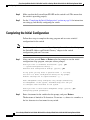
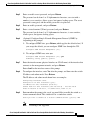
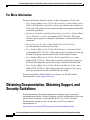
1
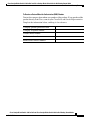
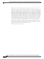
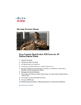
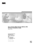
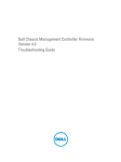
Cisco Catalyst Blade Switch
3130 for Dell and Cisco Catalyst Blade
Switch 3032 for Dell
Getting Started Guide
This guide provides instructions on how to install the Cisco Catalyst Blade Switch
3130 for Dell and the Cisco Catalyst Blade Switch 3032 for Dell—both hereafter
referred to as the switch—in the Dell Modular Server Chassis and how to set up
and configure your switch. The Dell Modular Server Chassis—hereafter referred
to as the server chassis—is a system that supports up to sixteen server modules
and up to six Ethernet switches. You install the switch in one of the chassis I/O
module bays on the rear panel of the server chassis.
Also covered in this guide are switch management options and troubleshooting
help for the switch.
For details on the number, types, and the location of the module bays and for
additional information on the entire modular server system, see the
documentation for the Dell PowerEdge Systems at www.support.dell.com.
For additional installation and configuration information about the switch, see the
Cisco Catalyst Blade Switch 3000 Series for Dell documentation on Cisco.com.
For system requirements, important notes, limitations, open and resolved caveats,
and last-minute documentation updates about the switch, see the release notes,
also on Cisco.com.
When you use the online publications, refer to the documents that match the Cisco
IOS software version that is running on the switch.
Cisco Catalyst Blade Switch 3130 for Dell and Cisco Catalyst Blade Switch 3032 for Dell Getting Started Guide
OL-14317-01
1
Cisco Catalyst Blade Switch 3130 for Dell and Cisco Catalyst Blade Switch 3032 for Dell Getting Started Guide
Contents
For translations of the warnings that appear in this publication, see the Regulatory
Compliance and Safety Information for the Cisco Catalyst Blade Switch 3000
Series for Dell that accompanies this guide.
Note
Before proceeding, read the release notes for the server chassis. The release notes
are available on the Dell support website at www.support.dell.com.
Contents
2
•
Taking Out What You Need, page 3
•
Switch Description, page 3
•
Dell Modular Server Chassis Architecture, page 6
•
Installation Warning Statements, page 7
•
Installing the Switch in the Server Chassis, page 8
•
Configuring the Switch, page 12
•
Managing the Switch, page 20
•
Planning and Creating a Switch Stack (Only 3130G-S and 3130X-S
Switches), page 22
•
Connecting to the Switch Ports, page 26
•
In Case of Difficulty, page 28
•
Obtaining Documentation, Obtaining Support, and Security Guidelines,
page 30
•
Hardware Warranty Terms, page 31
Cisco Catalyst Blade Switch 3130 for Dell and Cisco Catalyst Blade Switch 3032 for Dell Getting Started Guide
OL-14317-01
Cisco Catalyst Blade Switch 3130 for Dell and Cisco Catalyst Blade Switch 3032 for Dell Getting Started Guide
Taking Out What You Need
Taking Out What You Need
19X
17X
MODE
CONSOLE
M M S S
M S T Y
B T C S
R R K T
WS-CBS3130X-S
23
X2-2
24
20X
22
18X
21
X2-1
B
STK
A
These items ship with your switch:
Do
cu
m
CD enta
tio
n
250289
n
ct tio
du ta
ro n
P me
u
oc
D
Follow these steps:
Note
1.
Unpack and remove the switch and the accessory kit from the shipping box.
2.
Return the packing material to the shipping container, and save it for
future use.
If you order the switches with the server chassis, the switches are already
installed, and no unpacking is required. The unpacking procedure applies only if
you order a switch.
Switch Description
These are the available switch models:
Model
Description
CBS3032G
1-Gigabit Ethernet nonstacking-capable switch
CBS3130G-S
1-Gigabit Ethernet stacking-capable switch
CBS3130X-S
10-Gigabit Ethernet stacking-capable switch
Cisco Catalyst Blade Switch 3130 for Dell and Cisco Catalyst Blade Switch 3032 for Dell Getting Started Guide
OL-14317-01
3
Cisco Catalyst Blade Switch 3130 for Dell and Cisco Catalyst Blade Switch 3032 for Dell Getting Started Guide
Switch Description
The switch runs the universal software image that has the Cisco IOS code for
multiple feature sets. To enable a specific feature set, you must use the software
activation feature to install the software license for that feature set. For more
information, see the Cisco Software Activation Document for Dell, the release
notes, and the software configuration guide on Cisco.com.
Figure 1 shows the Cisco Catalyst Blade Switch 3130 for Dell as an example.
The other switch models have similar components.
Figure 1
Switch Front Panel
1
9
6
7
250198
5
MODE
CONSOLE
4
M M S S
M S T Y
B T C S
R R K T
WS-CBS3130X-S
2
3
10
23
X2-2
24
20X
22
18X
21
X2-1
2
STK
19X
1
17X
8
11
12 13
1
Switch
8
Release latch
2
StackWise Plus ports A and B (supported
only on the 3130G-S and 3130X-S
switches)
9
Cisco status LEDs
3
Gigabit Ethernet uplink ports 17 to 20
10 System Status/ID LED
4
LEDs for ports 21 and 22
11 Mode button
5
10-Gigabit Ethernet slot 1
or Gigabit Ethernet ports 21 and 22
12 Console port
6
LEDs for ports 23 and 24
13 Power LED
7
10-Gigabit Ethernet slot 2
or Gigabit Ethernet ports 23 and 24
For more information about the LEDs and their meanings, see the switch
hardware installation guide on Cisco.com.
4
Cisco Catalyst Blade Switch 3130 for Dell and Cisco Catalyst Blade Switch 3032 for Dell Getting Started Guide
OL-14317-01
Cisco Catalyst Blade Switch 3130 for Dell and Cisco Catalyst Blade Switch 3032 for Dell Getting Started Guide
Switch Description
Table 1 describes the switch ports.
Table 1
Cisco Catalyst Blade Switch 3130 for Dell and 3032 for Dell Port Descriptions
Port
Description
Ports 1 to 16
Internal Gigabit Ethernet 1000BASE-X downlink ports that connect the switch
to the server chassis blades.
Ports 17 to 20
External 10/100/1000BASE-T copper Gigabit Ethernet uplink ports that support
auto-MDIX, and autonegotiation.
Ports 21 to 24
10-Gigabit Ethernet module slots for use with the Cisco TwinGig Converter
Modules and Cisco X2 transceiver modules.
Internal
100BASE-T
Ethernet port
The internal 100BASE-T Ethernet port (Fa0) is used only for switch management
traffic, not for data traffic. It is connected to the Dell management console
through the server chassis backplane connector. Traffic to and from this port is
isolated from the switch ports.
Console port
Switch management serial port that uses an RJ-45 connector.
StackWise Plus
ports
Stacking cable ports (supported only on the 3130G-S and 3130X-S switches).
Each port has an associated LED. The System Status/ID LED is controlled
by the Dell Remote Access Controller/Modular Chassis (DRAC/MC)
management board.
For a list of supported modules, see the release notes on Cisco.com. For detailed
instructions on installing, removing, and connecting to SFP modules, see the
documentation that came with the SFP module.
Cisco Catalyst Blade Switch 3130 for Dell and Cisco Catalyst Blade Switch 3032 for Dell Getting Started Guide
OL-14317-01
5
Cisco Catalyst Blade Switch 3130 for Dell and Cisco Catalyst Blade Switch 3032 for Dell Getting Started Guide
Dell Modular Server Chassis Architecture
Dell Modular Server Chassis Architecture
The six chassis I/O module bays are on the rear panel (see Figure 2).
Figure 2
1
Dell Modular Server Chassis Rear Panel
2
3
4
5
6
7
8
9
10
!
!
!
B STK
A
18X
!
17X
!
11
20X
22
19X
21
X2-1
!
24
!
23
X2-2
!
WS-CB
S31
30X-S
!
M M
M S S S
B T T Y
R R C S
K T
MODE
CONSO
LE
!
!
!
!
!
12
!
!
6
250199
!
Cisco Catalyst Blade Switch 3130 for Dell and Cisco Catalyst Blade Switch 3032 for Dell Getting Started Guide
OL-14317-01
Cisco Catalyst Blade Switch 3130 for Dell and Cisco Catalyst Blade Switch 3032 for Dell Getting Started Guide
Installation Warning Statements
1
Dell server chassis
1
7
I/O module C2
2
Primary CMC module
8
I/O module B2
3
Switch installed in I/O module A1
9
I/O module A2
4
I/O module B1
10 Secondary CMC module2
5
I/O module C1
6
11 Fan modules
3
Optional iKVM module
12 Power supplies
1. CMC: Chassis Management Controller.
2. This module is optional.
3. iKVM: integrated keyboard video mouse.
For more information about the components of the information panel, see the Dell
documentation at www.support.dell.com.
Installation Warning Statements
This section includes the basic installation warning statements. Translations of
these warning statements appear in the Regulatory Compliance and Safety
Information for the Cisco Catalyst Blade Switch 3000 Series for Dell document
that shipped with the switch.
Warning
To prevent the switch from overheating, do not operate it in an area that
exceeds the maximum recommended ambient temperature of 113°F (45°C). To
prevent airflow restriction, allow at least 3 inches (7.6 cm) of clearance around
the ventilation openings. Statement 17B
Warning
Class 1 laser product. Statement 1008
Warning
Only trained and qualified personnel should be allowed to install, replace, or
service this equipment. Statement 1030
Cisco Catalyst Blade Switch 3130 for Dell and Cisco Catalyst Blade Switch 3032 for Dell Getting Started Guide
OL-14317-01
7
Cisco Catalyst Blade Switch 3130 for Dell and Cisco Catalyst Blade Switch 3032 for Dell Getting Started Guide
Installing the Switch in the Server Chassis
Warning
Ultimate disposal of this product should be handled according to all national
laws and regulations. Statement 1040
Warning
For connections outside the building where the equipment is installed, the
following ports must be connected through an approved network termination
unit with integral circuit protection: 10/100/1000 Ethernet. Statement 1044
Warning
Installation of the equipment must comply with local and national electrical
codes. Statement 1074
Installing the Switch in the Server Chassis
Before you install the switch in the server chassis, consider these points:
•
Review and become familiar with the safety and handling guidelines
specified in the Product Information Guide.
•
Review the Regulatory Compliance and Safety Information for the Cisco
Catalyst Blade Switch 3000 Series for Dell that ships with this product.
•
If you plan to create a switch stack, review the “Planning and Creating a
Switch Stack (Only 3130G-S and 3130X-S Switches)” section on page 22
before you install the switch and run the initial configuration setup program.
•
To help ensure proper cooling and system reliability, keep these points
in mind:
– Each chassis I/O module bay must contain either a module or an
input/output module (IOM) blank.
– When you remove a hot-swap module, you must replace it with an
identical module or an IOM blank within 1 minute of removal.
8
Cisco Catalyst Blade Switch 3130 for Dell and Cisco Catalyst Blade Switch 3032 for Dell Getting Started Guide
OL-14317-01
Cisco Catalyst Blade Switch 3130 for Dell and Cisco Catalyst Blade Switch 3032 for Dell Getting Started Guide
Installing the Switch in the Server Chassis
– You can install the switch into any of the module slots. If you install a
switch in the B or C module slot, the Ethernet mezzanine card must be
installed in the blade server.
– The dust covers should always remain in place unless a module is
installed in the slot.
Caution
To prevent electrostatic-discharge (ESD) damage when you install the switch,
follow your normal board and component handling procedures.
Note
When you install a switch, you do not need to power down the server chassis.
The initial configuration assumes that the switch was never configured, that it is
in the same state as when it was received, and that it is not configured with a
default username and password.
Follow these steps to install the switch into the server chassis:
Step 1
Obtain and make note of this information from your network administrator before
you begin the switch installation:
•
Switch IP address
•
Subnet mask (IP netmask)
•
Default gateway (router)
•
Enable secret password (encrypted)
•
Enable password (not encrypted)
•
Telnet password
•
SNMP community strings (optional)
Step 2
Select a chassis I/O module bay in which to install the switch. Follow the
prerequisites listed in the “Dell Modular Server Chassis Architecture” section on
page 6.
Step 3
Remove the IOM blank from the selected bay, and store it for future use.
Step 4
If you have not already done so, touch the static-protective package that contains
the switch to an unpainted metal part of the server chassis for at least 2 seconds.
Step 5
Remove the switch from its static-protective package.
Cisco Catalyst Blade Switch 3130 for Dell and Cisco Catalyst Blade Switch 3032 for Dell Getting Started Guide
OL-14317-01
9
Cisco Catalyst Blade Switch 3130 for Dell and Cisco Catalyst Blade Switch 3032 for Dell Getting Started Guide
Installing the Switch in the Server Chassis
Step 6
Ensure that the release latch on the switch is in the open position or perpendicular
to the module (see Figure 3):
Figure 3
Release Latch in Open Position
B STK
A
18X
17X
20X
22
24
19X
21
X2-1
23
X2-2
WS-CBS
3130
X-S
M M
M S S S
B T T Y
R R C S
K T
250200
MODE
CONS
OLE
10
Step 7
Slide the switch into the appropriate bay until it stops.
Step 8
Push the release latch on the front of the switch to the closed position.
Cisco Catalyst Blade Switch 3130 for Dell and Cisco Catalyst Blade Switch 3032 for Dell Getting Started Guide
OL-14317-01
Cisco Catalyst Blade Switch 3130 for Dell and Cisco Catalyst Blade Switch 3032 for Dell Getting Started Guide
Installing the Switch in the Server Chassis
Figure 4 shows the switch being inserted into the server chassis.
Figure 4
Inserting the Switch into the Server Chassis
2
!
!
!
B STK
1
!
A
18X
17X
!
20X
22
19X
21
X2-1
!
!
24
23
X2-2
!
!
WS-CBS
3
3130X-S
!
M M
M S S S
B T T Y
R R C S
K T
MODE
CONSOL
E
!
!
!
!
250201
!
!
!
1
Switch
2
Server chassis
3
Release latch
Cisco Catalyst Blade Switch 3130 for Dell and Cisco Catalyst Blade Switch 3032 for Dell Getting Started Guide
OL-14317-01
11
Cisco Catalyst Blade Switch 3130 for Dell and Cisco Catalyst Blade Switch 3032 for Dell Getting Started Guide
Configuring the Switch
Configuring the Switch
Note
To run the system configuration dialog, you must first connect the switch to a PC
to run a terminal emulation program. You can connect the switch to the PC: either
through the switch console port or through the DRAC/MC console port.
Instructions for these procedures are included in this section.
If you connect to the switch through the DRAC/MC, the switch console port is
disabled. After you have completed the configuration procedure, you must use the
disconnect command to close the active console port and re-enable the switch
console port. Type logout to log out of the switch, then enter Ctrl \ to disconnect
the DRAC/MC from the switch.
Follow one of these procedures:
•
To run the terminal emulation program through the switch console port, go to
“Connecting through the Switch Console Port” section on page 12.
•
To run the terminal emulation program through the DRAC/MC port, go to
“Connecting through the DRAC/MC” section on page 14.
Connecting through the Switch Console Port
Follow these steps when connecting through the switch console port:
Step 1
12
Connect one end of the console cable to the switch console port. Connect the other
end of the cable to the serial port of the PC that is running the terminal emulation
application. (See Figure 5.)
Cisco Catalyst Blade Switch 3130 for Dell and Cisco Catalyst Blade Switch 3032 for Dell Getting Started Guide
OL-14317-01
Cisco Catalyst Blade Switch 3130 for Dell and Cisco Catalyst Blade Switch 3032 for Dell Getting Started Guide
Configuring the Switch
Figure 5
Connecting To the Switch Console Port
!
WS-CBS
3130X-S
!
M M
M S S S
B T T Y
R R C S
K T
MODE
CONSOL
E
!
Step 2
250202
!
Start the terminal emulation session so that you can see the output display from
the power-on self-test (POST). The terminal-emulation software—a PC
application such as Hyperterminal or ProcommPlus—makes communication
between the switch and your PC or terminal possible.
Configure the baud rate and character format of the PC or terminal to match these
console port default characteristics:
Step 3
•
9600 baud
•
8 data bits
•
1 stop bit
•
No parity
•
None (flow control)
Go to the “Waiting for POST to Complete” section on page 15 to finish
configuring the switch.
Cisco Catalyst Blade Switch 3130 for Dell and Cisco Catalyst Blade Switch 3032 for Dell Getting Started Guide
OL-14317-01
13
Cisco Catalyst Blade Switch 3130 for Dell and Cisco Catalyst Blade Switch 3032 for Dell Getting Started Guide
Configuring the Switch
Connecting through the DRAC/MC
Follow these steps when connecting through the DRAC/MC:
Step 1
Connect one end of a DB9 null-modem or crossover cable to the RS-232 console
serial port of the DRAC/MC. Connect the other end of the cable to the RS-232
console serial port of the PC.
Step 2
On the PC terminal emulation program:
a.
Set the data format to 8 data bits, 1 stop bit, and no parity.
b.
Set the terminal emulation speed to 115200 baud.
c.
Set Flow Control to none.
d.
Under Properties, select VT100 for Emulation mode.
e.
Select Terminal keys for Function, Arrow, and Ctrl keys. Ensure that the
setting is for Terminal keys (not Windows keys).
When using HyperTerminal with Microsoft Windows 2000, ensure that you have
Windows 2000 Service Pack 2 or later installed. With Windows 2000 Service
Pack 2, the arrow keys function properly in the HyperTerminal VT100 emulation.
Go to www.microsoft.com for information on Windows 2000 service packs.
Step 3
On the console monitor, the DRAC/MC application displays a login screen.
Log in by using these defaults:
username root
password calvin
The DRAC/MC command-line interface (CLI) command prompt DRAC/MC:
appears.
Note
If the server chassis is off, use this command to power it on:
racadm chassisaction -m chassis powerup
The switch inserted into the chassis I/O bay automatically powers on
when the server chassis powers on. For more information on configuring
the server chassis by using the CLI, see the Dell Remote Access
Controller/Modular Chassis User's Guide.
14
Cisco Catalyst Blade Switch 3130 for Dell and Cisco Catalyst Blade Switch 3032 for Dell Getting Started Guide
OL-14317-01
Cisco Catalyst Blade Switch 3130 for Dell and Cisco Catalyst Blade Switch 3032 for Dell Getting Started Guide
Configuring the Switch
Power-cycle the switch by using this command:
racadm chassisaction -m switch-N powercycle
where N is the chassis I/O module bay number in which the switch is
inserted.
Step 4
Redirect the DRAC/MC console to the switch internal serial console interface.
Enter this command at the DRAC/MC command prompt:
connect switch-N
where N is the chassis I/O module bay number in which the switch is inserted.
To return to the command prompt, press this key sequence:
Enter Ctrl \ (Press Enter, and press the Control key and the backslash key
together.)
Step 5
Go to the “Waiting for POST to Complete” section on page 15 to finish
configuring the switch.
Waiting for POST to Complete
Follow these steps to verify that POST completes successfully:
Step 1
Wait for the switch to complete the POST. During POST, the LEDs blink while
tests verify that the switch functions properly. Wait for the switch to complete
POST, which can take several minutes.
Step 2
Verify that POST has completed by confirming that the SYST LED remains green.
If the switch fails POST, the SYST LED turns amber. See Figure 1 on page 4 for
the location of the SYST LED.
POST errors are usually fatal. Call Cisco Customer Support immediately if your
switch fails POST.
See the “In Case of Difficulty” section on page 28 if your switch fails POST.
Step 3
Wait for the switch to complete flash initialization. When you see the prompt
Press Return to Get Started!, press Return or Enter.
Cisco Catalyst Blade Switch 3130 for Dell and Cisco Catalyst Blade Switch 3032 for Dell Getting Started Guide
OL-14317-01
15
Cisco Catalyst Blade Switch 3130 for Dell and Cisco Catalyst Blade Switch 3032 for Dell Getting Started Guide
Configuring the Switch
Step 4
Make sure that the System Status/ID LED on the switch is off. This means that
the switch is operating properly.
Step 5
See the “Completing the Initial Configuration” section on page 16 for instructions
on setting up and initially configuring the switch.
Completing the Initial Configuration
Follow these steps to complete the setup program and to create an initial
configuration for the switch.
Note
Step 1
For information about automatically configuring the switch, see the “Assigning
the Switch IP Address and Default Gateway” chapter in the switch
configuration guide on Cisco.com.
After you have pressed Enter or Return after the prompt to start the initial
configuration setup program, enter yes at these prompts:
Would you like to terminate autoinstall? [yes]: yes
--- System Configuration Dialog --Continue with configuration dialog? [yes/no]: yes
At any point you may enter a question mark '?' for help.
Use ctrl-c to abort configuration dialog at any prompt.
Default settings are in square brackets '[]'.
Basic management setup configures only enough connectivity
for management of the system, extended setup will ask you
to configure each interface on the system
Would you like to enter basic management setup? [yes/no]: yes
Configuring global parameters:
Step 2
Enter a hostname for the switch after the prompt, and press Return.
The hostname is limited to 20 characters. Do not use -n, where n is a number, as
the last character in a host name for any switch.
16
Cisco Catalyst Blade Switch 3130 for Dell and Cisco Catalyst Blade Switch 3032 for Dell Getting Started Guide
OL-14317-01
Cisco Catalyst Blade Switch 3130 for Dell and Cisco Catalyst Blade Switch 3032 for Dell Getting Started Guide
Configuring the Switch
Step 3
Enter an enable secret password, and press Return.
The password can be from 1 to 25 alphanumeric characters, can start with a
number, is case sensitive, allows spaces, but ignores leading spaces. The secret
password is encrypted, and the enable password is in plain text.
Step 4
Enter an enable password, and press Return.
Step 5
Enter a virtual terminal (Telnet) password, and press Return.
The password can be from 1 to 25 alphanumeric characters, is case sensitive,
allows spaces, but ignores leading spaces.
Step 6
(Optional) Configure Simple Network Management Protocol (SNMP) by
responding to the prompts.
1.
To configure SNMP later, press Return (which applies the default of no). If
you accept the default, you can configure SNMP later through the CLI.
Configure SNMP Network Management? [no]:
2.
To configure SNMP now, enter yes.
Configure SNMP Network Management? [no]: yes
Community string [public]: public
Step 7
Enter the interface name (physical interface or VLAN name) of the interface that
connects to the management network, and press Return.
Enter vlan1 for the interface name at this prompt.
Step 8
To configure the interface, enter Yes after the prompt, and then enter the switch
IP address and subnet mask. Press Return.
The IP address and subnet mask shown here are examples:
Configuring interface Vlan1:
Configure IP on this interface? [yes]:
IP address for this interface [10.0.0.1]:
Subnet mask for this interface [255.255.255.0] : 255.255.255.0
Class A network is 10.0.0.1, 21 subnet bits; mask is /21
Step 9
Enter no when the prompt asks you if you would like to enable the switch as a
cluster command switch. This switch will be a standalone switch.
Would you like to enable as a cluster command switch? [yes/no]: no
Note
Clustering is not supported.
Cisco Catalyst Blade Switch 3130 for Dell and Cisco Catalyst Blade Switch 3032 for Dell Getting Started Guide
OL-14317-01
17
Cisco Catalyst Blade Switch 3130 for Dell and Cisco Catalyst Blade Switch 3032 for Dell Getting Started Guide
Configuring the Switch
You have now completed the initial configuration of the switch, and the switch
displays its initial configuration. An example of the output is shown here:
The following configuration command script was created:
hostname switch1
enable secret 5 $1$cagJ$e4LP91PNazfdADoNAZm6y0
enable password enable_password
line vty 0 15
password terminal-password
snmp-server community public
!
!
interface Vlan1
no shutdown
ip address 10.0.0.1 255.255.255.0
!
interface GigabitEthernet0/1
!
interface GigabitEthernet0/2
. . . (output truncated)
interface GigabitEthernet0/16
!
end
Step 10
These choices appear:
[0] Go to the IOS command prompt without saving this config.
[1] Return back to the setup without saving this config.
[2] Save this configuration to nvram and exit.
If you want to save the configuration and use it the next time the
switch reboots, save it in NVRAM by selecting option 2.
Enter your selection [2]:2
Make your selection, and press Return.
18
Cisco Catalyst Blade Switch 3130 for Dell and Cisco Catalyst Blade Switch 3032 for Dell Getting Started Guide
OL-14317-01
Cisco Catalyst Blade Switch 3130 for Dell and Cisco Catalyst Blade Switch 3032 for Dell Getting Started Guide
Configuring the Switch
Step 11
Disconnect the server chassis serial port or the switch console port from the PC.
See the “Managing the Switch” section on page 20 for information about
configuring and managing the switch.
If you need to rerun the initial configuration dialog, see the “Resetting the Switch
Configuration” section on page 29.
Configuring the Switch Stack Master
If you plan to create a switch stack, we recommend that you set the first
configured switch as the stack master. To do this, you must assign the highest
priority value to that switch. To assign a priority value after you have installed and
initially configured the first switch, follow these steps:
Step 1
Launch a Telnet session.
Step 2
Enter enable.
Step 3
Enter configure terminal.
Step 4
Enter switch 1 priority 15.
Step 5
At the prompt, press Return.
Step 6
Enter end to exit this mode.
Step 7
Enter copy running-configuration startup-configuration to save this setting.
Step 8
At the prompt, press Return.
Step 9
To verify that this switch is set as the master, enter the show switch user EXEC
command.
For more information about creating switch stacks, see the “Planning and
Creating a Switch Stack (Only 3130G-S and 3130X-S Switches)” section on
page 22.
Cisco Catalyst Blade Switch 3130 for Dell and Cisco Catalyst Blade Switch 3032 for Dell Getting Started Guide
OL-14317-01
19
Cisco Catalyst Blade Switch 3130 for Dell and Cisco Catalyst Blade Switch 3032 for Dell Getting Started Guide
Managing the Switch
Managing the Switch
After completing the initial setup and configuration steps, use the CLI, the device
manager, or other management options described in this section for further
configuration.
Using the CLI
After setting up and installing the switch in your network, you can enter
Cisco IOS commands and parameters through the CLI. Access the CLI either by
connecting your PC directly to the switch console port or through a Telnet session
from a remote PC or workstation. You can also access the CLI through the server
chassis serial console port of the active Dell CMC. For more information, see the
hardware installation guide on Cisco.com.
Using the Device Manager
The simplest way to manage the switch is by using the device manager that is in
the switch memory. This is an easy-to-use web interface that offers quick
configuration and monitoring. You can access the device manager from anywhere
in your network through a web browser. The device manager dashboard is shown
in Figure 6.
20
Cisco Catalyst Blade Switch 3130 for Dell and Cisco Catalyst Blade Switch 3032 for Dell Getting Started Guide
OL-14317-01
Cisco Catalyst Blade Switch 3130 for Dell and Cisco Catalyst Blade Switch 3032 for Dell Getting Started Guide
Managing the Switch
Figure 6
Device Manager Dashboard
Follow these steps to access the device manager:
1.
Launch a web browser on your PC or workstation.
2.
Enter the switch IP address in the web browser, and press Enter. The device
manager page appears.
3.
Use the device manager to perform basic switch configuration and
monitoring. See the device manager online help for more information.
Cisco Catalyst Blade Switch 3130 for Dell and Cisco Catalyst Blade Switch 3032 for Dell Getting Started Guide
OL-14317-01
21
Cisco Catalyst Blade Switch 3130 for Dell and Cisco Catalyst Blade Switch 3032 for Dell Getting Started Guide
Planning and Creating a Switch Stack (Only 3130G-S and 3130X-S Switches)
Other Management Options
You can use SNMP management applications such as CiscoWorks. You also can
manage it from an SNMP-compatible workstation that is running platforms such
as SunNet Manager.
See the “Accessing Help Online” section on page 29 for a list of supporting
documentation.
Planning and Creating a Switch Stack (Only 3130G-S
and 3130X-S Switches)
A switch stack is a set of up to nine stacking-capable switches that are connected
through their StackWise Plus ports. One switch controls the operation of the stack
and is called the stack master. The stack master and the other switches in the stack
are stack members. Layer 2 and Layer 3 protocols present the entire switch stack
as a single entity to the network. Stacking is optional.
When switches are not stacked, each acts as a standalone switch. For general
concepts and procedures to manage switch stacks, see the switch software
configuration guide and command reference on Cisco.com.
Caution
The Cisco Catalyst Blade Switch 3130 for Dell and the Cisco Catalyst Blade
Switch 3032 for Dell do not support switch stacks with other types of blades
switches as members. Combining the stacking-capable blade switches for Dell
with other types of blade switches in a switch stack might cause the switch to
work improperly or to fail.
Before you connect the switches in a stack, keep in mind these stacking
guidelines:
•
22
You should install the stack master switch and run the initial setup program
on that switch before you connect the StackWise Plus cables to other stack
members. We recommend that you assign the highest priority value to the
switch that you prefer to be the stack master. This ensures that the switch is
re-elected as stack master if a re-election occurs. As you add new switches to
the stack, they automatically become stack members.
Cisco Catalyst Blade Switch 3130 for Dell and Cisco Catalyst Blade Switch 3032 for Dell Getting Started Guide
OL-14317-01
Cisco Catalyst Blade Switch 3130 for Dell and Cisco Catalyst Blade Switch 3032 for Dell Getting Started Guide
Planning and Creating a Switch Stack (Only 3130G-S and 3130X-S Switches)
To assign a priority value after you have installed and initially configured the
first switch, see the “Configuring the Switch Stack Master” section on
page 19.
•
When you connect the StackWise Plus cables and create a stack, you can
communicate with the master switch internal Ethernet management port
(Fa0) port, but not the Fa0 ports of the member switches. Only one Fa0
interface can be active, and that interface is the one on the active stack master.
•
For conditions that might cause a stack master re-election or to manually elect
the stack master, see the “Managing Switch Stacks” chapter in the switch
software configuration guide on Cisco.com.
•
You can stack any combination of up to nine Catalyst 3130G-S and 3130X-S
switches. You can stack only the Catalyst 3130 switches; other switches
cannot be stacked.
•
Before installation, verify the StackWise Plus cable length. Depending on
your configuration, you might need different sized cables. If you do not
specify the length of the StackWise Plus cable when you order your product,
the 1-meter cable is supplied. If you need the 0.5-meter cable or the 3-meter
cable, you can order these StackWise Plus cables from your Cisco sales
representative:
– CAB-STK-E-0.5M= (0.5-meter cable)
– CAB-STK-E-1M= (1-meter cable)
– CAB-STK-E-3M= (3-meter cable)
For switch dimensions, StackWise Plus cable part numbers, and additional
stacking guidelines, see the switch hardware installation guide on Cisco.com. For
concepts and procedures to manage switch stacks, see the switch software
configuration guide and the stack compatibility guide, also on Cisco.com.
To create a switch stack:
•
Install the member switches if you have not already done so.
•
Connect the StackWise Plus cables as described in the “Planning and
Creating a Switch Stack (Only 3130G-S and 3130X-S Switches)” section on
page 22.
•
Configure the member switches through the master switch by using the CLI.
Cisco Catalyst Blade Switch 3130 for Dell and Cisco Catalyst Blade Switch 3032 for Dell Getting Started Guide
OL-14317-01
23
Cisco Catalyst Blade Switch 3130 for Dell and Cisco Catalyst Blade Switch 3032 for Dell Getting Started Guide
Planning and Creating a Switch Stack (Only 3130G-S and 3130X-S Switches)
Stack Cabling Configuration Example
This section shows one stacking example in which a single chassis with two
switches in a single server chassis create one stack. Many other types of
configurations are possible provided that you stack no more than nine switches.
For more configuration examples, see the hardware installation guide on
Cisco.com.
In this example, the stack uses the 1-meter StackWise Plus cable to make
redundant connections between two Catalyst 3130 switches in a single chassis
(see Figure 7).
Figure 7
Example of a Single Chassis with Two Switches and One Stack
B
24
STK
23
B
A
24
STK
A
23
X2-2
WS-CBS31
30X-S
WS-CBS31
30X-S
250291
X2-2
24
Cisco Catalyst Blade Switch 3130 for Dell and Cisco Catalyst Blade Switch 3032 for Dell Getting Started Guide
OL-14317-01
Cisco Catalyst Blade Switch 3130 for Dell and Cisco Catalyst Blade Switch 3032 for Dell Getting Started Guide
Planning and Creating a Switch Stack (Only 3130G-S and 3130X-S Switches)
Connecting the StackWise Plus Cables
Follow these steps to connect the StackWise Plus cables:
Step 1
Remove the dust covers from the StackWise Plus cables, and store them for
future use.
Step 2
Verify that cables are aligned as shown in Figure 8.
Figure 8
Inserting the StackWise Plus Cable
B STK
A
18X
20X
22
Step 3
19X
21
250315
17X
Insert one end of the cable into the StackWise Plus port on the front panel of the
switch. Insert the other end of the cable into the connector on the other switch (see
Figure 8).
Always use a Cisco-approved StackWise Plus cable to connect the switches.
When you remove the StackWise Plus cables from the connectors, replace the dust
covers to protect them from dust.
Caution
Removing and installing the StackWise Plus cable can shorten its useful life. Do
not remove and insert the cable more often than is absolutely necessary.
Cisco Catalyst Blade Switch 3130 for Dell and Cisco Catalyst Blade Switch 3032 for Dell Getting Started Guide
OL-14317-01
25
Cisco Catalyst Blade Switch 3130 for Dell and Cisco Catalyst Blade Switch 3032 for Dell Getting Started Guide
Connecting to the Switch Ports
Connecting to the Switch Ports
This section describes how to connect to the fixed switch ports and to the
10-Gigabit Ethernet module slots.
Connecting to 10/100/1000 Ports
The 10/100/1000 Ethernet ports use standard RJ-45 connectors with Ethernet
pinouts. The maximum cable length is 328 feet (100 meters). The 100BASE-TX
and 1000BASE-T traffic requires Category 5, Category 5e, or Category 6 UTP
cable. The 10BASE-T traffic can use Category 3 or Category 4 cable.
The autonegotiation feature is enabled by default on the switch. At this setting,
the switch ports configure themselves to operate at the speed of attached devices.
If the attached device does not support autonegotiation, you can explicitly set the
switch port speed and the duplex parameters. To maximize performance, either let
the ports autonegotiate both speed and duplex, or set the port speed and duplex
parameters on both ends of the connection.
For simplified cabling, the automatic medium-dependent interface crossover
(auto-MDIX) feature is enabled by default. With auto-MDIX enabled, the switch
detects the required cable type for copper Ethernet connections and configures the
interface accordingly. Therefore, you can use either a crossover or a
straight-through cable for connections to a switch 10/100/1000 Ethernet port,
regardless of the type of device on the other end of the connection.
See the switch software configuration guide or the switch command reference on
Cisco.com for more information about enabling or disabling autonegotiation and
auto-MDIX.
26
Cisco Catalyst Blade Switch 3130 for Dell and Cisco Catalyst Blade Switch 3032 for Dell Getting Started Guide
OL-14317-01
Cisco Catalyst Blade Switch 3130 for Dell and Cisco Catalyst Blade Switch 3032 for Dell Getting Started Guide
Connecting to the Switch Ports
Installing and Connecting to Devices in the 10-Gigabit
Ethernet Slots
The switch 10-Gigabit Ethernet module slots are used for connections to other
switches and routers. The module slots operate in full-duplex mode and use the
hot-swappable Cisco X2 transceiver modules and the Cisco TwinGig Converter
Module. The X2 transceiver modules have SC connectors to connect to multimode
fiber (MMF) and single-mode fiber (SMF) cables. The Cisco converter modules
have two SFP-module slots that convert the 10-Gigabit interface into a dual SFP
module interface.
Figure 9 shows how to install an X2 transceiver module into the 10-Gigabit port.
Figure 9
Installing an X2 Transceiver Module
B STK
A
18X
17X
20X
24
19X
21
X2-1
23
X2-2
250309
22
Use only Cisco X2 transceiver modules, Cisco converter modules, and Cisco SFP
modules with the switch. Each Cisco module has an internal serial EEPROM that
is encoded with security information. This encoding provides a way for Cisco to
identify and validate that the module meets the requirements for the switch.
Cisco Catalyst Blade Switch 3130 for Dell and Cisco Catalyst Blade Switch 3032 for Dell Getting Started Guide
OL-14317-01
27
Cisco Catalyst Blade Switch 3130 for Dell and Cisco Catalyst Blade Switch 3032 for Dell Getting Started Guide
In Case of Difficulty
Verify Port Connectivity
After you connect a device to the switch port, the port LED turns amber while the
switch establishes a link. This process takes about 30 seconds. The LED turns
green when the switch and the attached device have an established link. If the
LED is off, the device might not be turned on, there might be a cable problem, or
there might be a problem with the adapter installed in the device. See the “In Case
of Difficulty” section on page 28 for information about online assistance.
In Case of Difficulty
If you experience difficulty, help is available in this section and on Cisco.com.
Also review the Dell server chassis documentation on the Dell support website at
www.support.dell.com.
This section includes initial setup troubleshooting, how to reset the switch, how
to access help online, and where to find more information.
Troubleshooting Initial Configuration Setup
If you have problems running the initial configuration dialog:
•
Did you verify that POST successfully ran
before running the initial configuration
dialog?
POST errors are usually fatal. Call Cisco
Customer Support immediately if your switch fails
POST.
•
Did you lock yourself out and forget your
password?
See the “Recovering from a Lost or Forgotten
Password” section in the Troubleshooting
appendix of the software configuration guide on
Cisco.com if you forget your password.
28
Cisco Catalyst Blade Switch 3130 for Dell and Cisco Catalyst Blade Switch 3032 for Dell Getting Started Guide
OL-14317-01
Cisco Catalyst Blade Switch 3130 for Dell and Cisco Catalyst Blade Switch 3032 for Dell Getting Started Guide
Accessing Help Online
Resetting the Switch Configuration
This section describes how to reset the switch configuration by rerunning the
initial configuration dialog (System Configuration Dialog). These are reasons
why you might want to reset the switch:
Caution
•
You installed the switch in your network and cannot connect to it because you
assigned the wrong IP address.
•
You want to clear the configuration from the switch and assign a new IP
address.
Resetting the switch deletes the configuration and reboots the switch.
To reset the switch:
•
At the switch prompt, enter enable and press Return or Enter.
•
At the privileged EXEC prompt (switch#) enter setup, and press
Return or Enter.
The switch displays the prompt to run the initial configuration dialog. See the
“Configuring the Switch” section on page 12 to re-enter the configuration
information and to set up your switch.
Accessing Help Online
For a solution to your problem, look in the troubleshooting section of the
hardware installation guide or the software configuration guide on Cisco.com.
You can also access the Cisco Technical Support and Documentation website for
a list of known hardware problems and extensive troubleshooting documentation.
Cisco Catalyst Blade Switch 3130 for Dell and Cisco Catalyst Blade Switch 3032 for Dell Getting Started Guide
OL-14317-01
29
Cisco Catalyst Blade Switch 3130 for Dell and Cisco Catalyst Blade Switch 3032 for Dell Getting Started Guide
Obtaining Documentation, Obtaining Support, and Security Guidelines
For More Information
For more information about the switch, see these documents on Cisco.com:
•
Cisco Catalyst Blade Switch 3130 for Dell and Cisco Catalyst Blade Switch
3032 for Dell Hardware Installation Guide (not orderable, but available on
Cisco.com). This guide provides complete hardware descriptions and detailed
installation procedures.
•
Regulatory Compliance and Safety Information for the Cisco Catalyst Blade
Switch 3000 Series for Dell (order number DOC-7817053=). This guide
contains agency approvals, compliance information, and translated warning
statements.
•
Release Notes for the Cisco Catalyst Blade Switch 3130 for Dell
(not orderable but available on Cisco.com)
•
Cisco Catalyst Blade Switch 3130 for Dell Software Configuration Guide
(order number DOC-7817261=). This guide provides a product overview and
detailed descriptions and procedures of the switch software features.
•
Cisco Catalyst Blade Switch 3130 for Dell Command Reference (order
number DOC-7817262=). This reference provides detailed descriptions of
the Cisco IOS commands specifically created or modified for the switch.
•
Cisco Catalyst Blade Switch 3130 for Dell System Message Guide (order
number DOC-7817263=). This guide provides descriptions of the system
messages specifically created or modified for the switch.
For more information about the Dell server chassis, see the Dell product
documentation at www.support.dell.com.
Obtaining Documentation, Obtaining Support, and
Security Guidelines
For information on obtaining documentation, obtaining support, providing
documentation feedback, security guidelines, and also recommended aliases and
general Cisco documents, see the monthly What's New in Cisco Product
Documentation, which also lists all new and revised Cisco technical
documentation, at:
http://www.cisco.com/en/US/docs/general/whatsnew/whatsnew.html
30
Cisco Catalyst Blade Switch 3130 for Dell and Cisco Catalyst Blade Switch 3032 for Dell Getting Started Guide
OL-14317-01
Cisco Catalyst Blade Switch 3130 for Dell and Cisco Catalyst Blade Switch 3032 for Dell Getting Started Guide
Hardware Warranty Terms
Hardware Warranty Terms
This section describes the warranty terms for the switch.
Dell Hardware Warranty Terms
Note
Important Note about Your Warranty: The limited warranty below reflects the
extent of the Cisco warranty for the Cisco Catalyst Blade Switch 3130 for Dell
and Cisco Catalyst Blade Switch 3032 for Dell. If you purchased this product
from Dell, Dell might provide an additional warranty that is different than the
limited warranty terms below. See the Product Information Guide included with
your Dell branded server product for the applicable warranty information. This
additional warranty is provided by Dell and not by Cisco; please see your
authorized Dell representative for any questions or claims related to this warranty.
Cisco disclaims any warranty other than as specifically provided below.
Cisco 90-Day Limited Hardware Warranty Terms
There are special terms applicable to your hardware warranty and various services
that you can use during the warranty period. Your formal Warranty Statement,
including the warranties and license agreements applicable to Cisco software, is
available on Cisco.com. Follow these steps to access and download the Cisco
Information Packet and your warranty and license agreements from Cisco.com.
1.
Launch your browser, and go to this URL:
http://www.cisco.com/univercd/cc/td/doc/es_inpck/cetrans.htm
The Warranties and License Agreements page appears.
2.
To read the Cisco Information Packet, follow these steps:
a. Click the Information Packet Number field, and make sure that the part
number 78-5235-03C0 is highlighted.
b. Select the language in which you would like to read the document.
Cisco Catalyst Blade Switch 3130 for Dell and Cisco Catalyst Blade Switch 3032 for Dell Getting Started Guide
OL-14317-01
31
Cisco Catalyst Blade Switch 3130 for Dell and Cisco Catalyst Blade Switch 3032 for Dell Getting Started Guide
Hardware Warranty Terms
c. Click Go.
The Cisco Limited Warranty and Software License page from the
Information Packet appears.
d. Read the document online, or click the PDF icon to download and print
the document in Adobe Portable Document Format (PDF).
Note
3.
You must have Adobe Acrobat Reader to view and print PDF
files. You can download the reader from Adobe’s website:
http://www.adobe.com
To read translated and localized warranty information about your product,
follow these steps:
a. Enter this part number in the Warranty Document Number field:
78-5236-01C0
b. Select the language in which you would like to read the document.
c. Click Go.
The Cisco warranty page appears.
d. Review the document online, or click the PDF icon to download and print
the document in Adobe Portable Document Format (PDF).
You can also contact the Cisco service and support website for assistance:
http://www.cisco.com/public/Support_root.shtml.
Duration of Hardware Warranty
Ninety (90) days.
Replacement, Repair, or Refund Policy for Hardware
Cisco or its service center will use commercially reasonable efforts to ship a
replacement part within ten (10) working days after receipt of a Return Materials
Authorization (RMA) request. Actual delivery times can vary, depending on the
customer location.
Cisco reserves the right to refund the purchase price as its exclusive warranty
remedy.
32
Cisco Catalyst Blade Switch 3130 for Dell and Cisco Catalyst Blade Switch 3032 for Dell Getting Started Guide
OL-14317-01
Cisco Catalyst Blade Switch 3130 for Dell and Cisco Catalyst Blade Switch 3032 for Dell Getting Started Guide
Hardware Warranty Terms
To Receive a Return Materials Authorization (RMA) Number
Contact the company from whom you purchased the product. If you purchased the
product directly from Cisco, contact your Cisco Sales and Service Representative.
Complete the information below, and keep it for reference:
Company product purchased from
Company telephone number
Product model number
Product serial number
Maintenance contract number
Cisco Catalyst Blade Switch 3130 for Dell and Cisco Catalyst Blade Switch 3032 for Dell Getting Started Guide
OL-14317-01
33
Cisco Catalyst Blade Switch 3130 for Dell and Cisco Catalyst Blade Switch 3032 for Dell Getting Started Guide
Hardware Warranty Terms
This document is to be used in conjunction with the documents listed in the “For More Information” section.
CCVP, the Cisco logo, and the Cisco Square Bridge logo are trademarks of Cisco Systems, Inc.; Changing the Way
We Work, Live, Play, and Learn is a service mark of Cisco Systems, Inc.; and Access Registrar, Aironet, BPX,
Catalyst, CCDA, CCDP, CCIE, CCIP, CCNA, CCNP, CCSP, Cisco, the Cisco Certified Internetwork Expert logo,
Cisco IOS, Cisco Press, Cisco Systems, Cisco Systems Capital, the Cisco Systems logo, Cisco Unity,
Enterprise/Solver, EtherChannel, EtherFast, EtherSwitch, Fast Step, Follow Me Browsing, FormShare, GigaDrive,
HomeLink, Internet Quotient, IOS, iPhone, IP/TV, iQ Expertise, the iQ logo, iQ Net Readiness Scorecard, iQuick
Study, LightStream, Linksys, MeetingPlace, MGX, Networking Academy, Network Registrar, PIX, ProConnect,
ScriptShare, SMARTnet, StackWise, The Fastest Way to Increase Your Internet Quotient, and TransPath are
registered trademarks of Cisco Systems, Inc. and/or its affiliates in the United States and certain other countries.
All other trademarks mentioned in this document or Website are the property of their respective owners. The use of
the word partner does not imply a partnership relationship between Cisco and any other company. (0708R)
Any Internet Protocol (IP) addresses used in this document are not intended to be actual addresses. Any examples,
command display output, and figures included in the document are shown for illustrative purposes only. Any use of
actual IP addresses in illustrative content is unintentional and coincidental.
© 2007 Cisco Systems, Inc. All rights reserved.
34
Cisco Catalyst Blade Switch 3130 for Dell and Cisco Catalyst Blade Switch 3032 for Dell Getting Started Guide
OL-14317-01