1
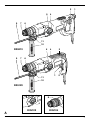
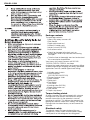
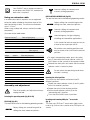
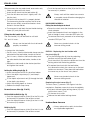
D25122(K)
D25123(K)
D25124(K)
D25213(K)
English
6
Copyright DE WALT
2
3
9
7
5
4
5
4
1
6
11
10
D25213
9
7
3
6
1
11
10
2
D25123
8
4
A
D25122
D25124
3
5
4
6
B1
5
B2
7
4
12
C
10
9
D
4
E
11
3
3
F1
F2
8
6
13
G
8
H
5
ENGLISH
HEAVY DUTY ROTARY HAMMER DRILL
D25122(K)/D25123(K)/D25124(K)/D25213(K)
Congratulations!
You have chosen a DEWALT tool. Years of experience, thorough product development and innovation make
DEWALT one of the most reliable partners for professional power tool users.
Technical data
Voltage
Power input
No-load speed
Load speed
Impact energy
hammer drilling
chiselling
Maximum drilling range in
steel/wood/concrete
Chisel positions
Core drilling capacity in soft brick
Tool holder
Collar diameter
Weight
V
W
min-1
min-1
D25122(K)
220-240
800
0 - 1,150
0 - 830
J 3.1
J mm 13/30/26
mm 68
SDS-plus®
mm 54
kg 2.55
The following symbols are used throughout this
manual:
Denotes risk of personal injury, loss of life
or damage to the tool in case of nonobservance of the instructions in this
manual.
Denotes risk of electric shock.
Fire hazard.
6
D25123K
220-240
800
0 - 1,150
0 - 830
D25124K
220-240
800
0 - 1,150
0 - 830
220-240
800
0 - 1,150
0 - 830
3.1
3.4
3.1
3.4
3.1
3.4
13/30/26
52
68
SDS-plus®
54
2.6
13/30/26
52
68
SDS-plus®
54
2.6
13/30/26
52
68
SDS-plus®
54
2.75
ENGLISH
7
ENGLISH
Package contents
The package contains:
1 Heavy duty rotary hammer drill
1 Side handle
1 Depth adjustment rod
1 Kitbox (K-models only)
1 Keyless chuck (D25124)
1 Instruction manual
Check for damage to the tool, parts or
accessories which may have occurred during
transport.
Take the time to thoroughly read and understand
this manual prior to operation.
Your heavy duty rotary hammer drill D25122/
D25123/ D25124/ D25213 has been
designed for professional rotary and hammer drilling,
screwdriving and light chipping, chiselling, demolition
applications and for carbide tipped core drilling.
1 Variable speed switch
2 Lock-on button
(D25122/D25123/D25124)
3 Forward/reverse slider
4 Mode selector
5 Safety lock
6 Tool holder
7 Dust cover
8 Locking collar (D25124)
9 Depth adjustment rod
10 Side handle
11 Depth stop clamp
Torque limiting clutch
All rotary hammer drills are equipped with a torque
limiting clutch that reduces the maximum torque
reaction transmitted to the operator in case of
jamming of a drill bit. This feature also prevents the
gearing and electric motor from stalling. The torque
limiting clutch has been factory-set and cannot be
adjusted.
Electrical safety
The electric motor has been designed for one
voltage only. Always check that the power supply
corresponds to the voltage on the rating plate.
8
ENGLISH
Your DEWALT tool is double insulated in
accordance with IEC60745; therefore no
earth wire is required.
D25123K/D25124K/D25213K (fig. B2)
The tool can be used in the following operating modes:
Using an extension cable
If an extension cable is required, use an approved
extension cable suitable for the power input of this
tool (see technical data). The minimum conductor
size is 1.5 mm2.
When using a cable reel, always unwind the cable
completely.
Also refer to the table below.
Conductor size (mm 2 )
0.75
1.00
1.50
2.50
4.00
230
Amperes
0 - 2 .0
2.1 - 3.4
3.5 - 5.0
5.1 - 7.0
7.1 - 12.0
12.1 - 20.0
0 - 2.0
2.1 - 3.4
3.5 - 5.0
5.1 - 7.0
7.1 - 12.0
12.1 - 20.0
15
Hammer drilling: for concrete and
masonry drilling operations.
In this mode the tool can also be used as
a lever to free a jammed drill bit.
0
Cable length (m)
25 30
45
Cable rating (Amperes)
6
6
6
6
6
6
6
6
6
6
10 15
10 10
15 20
15 15
20 25
20 20
25
6
6
6
6
6
6
6
6
6
6
6
6
10 10
10 10
15 15
15 15
20 20
20 20
Rotary drilling: for screwdriving and for
drilling into steel, wood and plastics
Hammering only: for light chipping,
chiselling and demolition applications.
Cable rating (Amperes)
6
10
15
20
25
7.5
Voltage
115
Hammer drilling: for concrete and
masonry drilling operations.
6
15
20
20
25
6
6
10
15
20
25
60
1
15
20
25
6
6
15
15
20
-
Assembly and adjustment
Prior to assembly and adjustment always
unplug the tool.
Bit rotation: non-working position used
only to rotate a flat chisel into the desired
position.
To select the operating mode, press the safety
lock (5) and rotate the mode selector switch (4)
until it points to the symbol of the required mode.
Release the safety lock and check that the mode
selector switch is locked in place.
Do not select the operating mode when
the tool is running.
Indexing the chisel position
The chisel can be indexed and locked into 52
different positions.
Rotate the mode selector switch (4) until it points
to the “bit rotation” position.
Rotate the chisel in the desired position.
Set the mode selector switch (4) to the
“hammering only” position.
Twist the chisel until it locks in position.
Selecting the operating mode (fig. B1 & B2)
D25122(K) (fig. B1)
The tool can be used in the following operating modes:
Rotary drilling: for screwdriving and for
drilling into steel, wood and plastics
Inserting and removing SDS-plus ® accessories
(fig. C)
This tool uses SDS-plus® accessories (refer to the
inset in fig. B for a cross-section of an SDS-plus® bit
shank).
9
ENGLISH
We recommend to use professional accessories only.
Clean and grease the bit shank.
Insert the bit shank into the tool holder (6).
Push the bit down and turn it slightly until it fits
into the slots.
Pull on the bit to check if it is properly locked.
The hammering function requires the bit to be
able to move axially several centimetres when
locked in the tool holder.
To remove a bit pull back the tool holder locking
sleeve (12) and pull out the bit.
Fitting the side handle (fig. D)
The side handle (10) can be fitted to suit both
RH- and LH-users.
Always use the tool with the side handle
properly assembled.
Loosen the side handle.
For RH-users, slide the side handle clamp over the
collar behind the tool holder, handle at the left.
For LH-users, slide the side handle clamp over
the collar behind the tool holder, handle at the
right.
Rotate the side handle to the desired position
and tighten the handle.
Setting the drilling depth (fig. E)
Insert the required drill bit as described above.
Press the depth stop clamp (11) and keep it
depressed.
Fit the depth adjustment rod (9) through the hole
in the depth stop clamp.
Adjust the drilling depth as shown.
Release the depth stop clamp.
Forward/reverse slider (fig. F1 & F2)
D25122/D25123/D25124 (fig. F1)
Push the forward/reverse slider (3) to the RH-side
for forward (RH) rotation. See arrows on tool.
Push the forward/reverse slider (3) to the LH-side
for reverse (LH) rotation.
D25213 (fig. F2)
Push the forward/reverse slider (3) to the LH-side
for forward (RH) rotation. See arrows on tool.
10
Push the forward/reverse slider (3) to the RH-side
for reverse (LH) rotation.
Always wait until the motor has come to
a complete standstill before changing the
direction of rotation.
D25122/D25123/D25213 Fitting the chuck adapter & chuck
Screw the chuck onto the threaded end of the
chuck adapter.
Insert the connected chuck and adapter in the
tool as though it were a standard SDS-plus® bit.
To remove the chuck, proceed as for removing a
standard SDS-plus® bit.
Never use standard chucks in the
hammer drilling mode.
D25124 - Replacing the tool holder with
the chuck (fig. G)
Turn the locking collar (8) into the unlocking
position and pull the tool holder (6) off.
Push the chuck (13) onto the spindle and turn the
locking collar into the locking position.
To replace the chuck with the tool holder,
first remove the chuck the same way as the tool
holder was removed. Then place the tool holder
the same way as the chuck was placed.
Never use standard chucks in the
hammer drilling mode.
Replacing the dust cover (fig. C)
The dust cover (7) prevents dust ingress into the
mechanism. Replace a worn dust cover immediately.
Pull back the tool holder locking sleeve (12) and
pull the dust cover (7) off.
Fit the new dust cover.
Release the tool holder locking sleeve.
Instructions for use
Always observe the safety instructions
and applicable regulations.
ENGLISH
Be aware of the location of pipework and wiring.
Apply only a gentle pressure to the tool (approx. 5 kg).
Excessive force does not speed up drilling but
decreases tool performance and may shorten tool
life.
Do not drill or drive too deep to prevent damage to
the dust cover.
Always hold the tool firmly with both hands and
ensure a secure stance (fig. H). Always operate the
tool with the side handle properly mounted.
Switching on and off (fig. A)
D 25122/D25123/D25124
To run the tool, press the variable speed switch
(1). The pressure exerted on the variable speed
switch determines the tool speed.
For continuous operation, press and hold down
the variable speed switch, press the lock-on
button (2) and release the switch.
To stop the tool, release the switch.
To stop the tool in continuous operation, press
the switch briefly and release it. Always switch off
the tool when work is finished and before
unplugging.
D 25213
To run the tool, press the variable speed switch
(1). The pressure exerted on the variable speed
switch determines the tool speed.
To stop the tool, release the switch.
To lock the tool in off position, move the forward/
reverse slider (3) to the central position.
Hammer drilling (fig. A)
Drilling with a solid bit
Set the mode selector switch (4) to the
“hammer drilling” position.
Insert the appropriate drill bit. For best results
use high quality carbide-tipped bits.
Adjust the side handle (10) as required.
If necessary, set the drilling depth.
Mark the spot where the hole is to be drilled.
Place the drill bit on the spot and switch on the
tool.
Always switch off the tool when work is finished
and before unplugging.
Drilling with a core bit
Set the mode selector (4) to the “hammer drilling”
position.
Adjust the side handle (10) as required.
Insert the appropriate core bit.
Assemble the centerdrill into the core bit.
Place the centerdrill on the spot and press the
variable speed switch (1). Drill until the core
penetrates into the concrete approx. 1 cm.
Stop drilling and remove the centerdrill. Place the
core bit back into the hole and continue drilling.
When drilling through a structure thicker than the
depth of the core bit, break away the round
cylinder of concrete or core inside the bit at
regular intervals. To avoid unwanted breaking
away of concrete around the hole, first drill a hole
the diameter of the centerdrill completely through
the structure. Then drill the cored hole halfway
from each side.
Always switch off the tool when work is finished
and before unplugging.
Rotary drilling (fig. A)
Set the mode selector switch (4) to the “rotary
drilling” position.
Depending on your tool, follow either of the
following instructions:
- Fit the chuck adapter/chuck assembly
(D25122/D25123/D25213).
- Replace the tool holder with the chuck
(D25124).
Proceed as described for hammer drilling.
Never use standard chucks in the
hammer drilling mode.
Screwdriving (fig. A)
Set the mode selector switch (4) to the “rotary
drilling” position.
Select the direction of rotation.
Depending on your tool, follow either of the
following instructions:
- Insert the special SDS-plus® screwdriving
adaptor for use with hexagonal screwdriver bits
(D25122/D25123/D25213).
- Replace the tool holder with the chuck
(D25124).
11
ENGLISH
Insert the appropriate screwdriver bit.
When driving slotted head screws always use
bits with a finder sleeve.
Gently press the variable speed switch (1) to
prevent damage to the screw head. In reverse
(LH) rotation the tool speed is automatically
reduced for easy screw removal.
When the screw is flush with the workpiece,
release the variable speed switch to prevent the
screw head from penetrating into the workpiece.
D 25123K/D25124K/D25213K - Chipping and
chiselling (fig. A)
Set the mode selector switch (4) to the
“hammering only” position.
Insert the appropriate chisel and rotate it by hand
to lock it into one of 52 positions.
Adjust the side handle (10) as required.
Switch on the tool and start working.
Always switch off the tool when work is finished
and before unplugging.
Lubrication
Your power tool requires no additional lubrication.
Accessories and attachments used must be
regularly lubricated around the SDS-plus® fitment.
Cleaning
Keep the ventilation slots clear and regularly clean
the housing with a soft cloth.
Unwanted tools and the environment
Take your tool to an authorized DEWALT repair
agent where it will be disposed of in an
environmentally safe way.
Do not use this tool to mix or pump
easily combustible or explosive fluids
(benzine, alcohol, etc.).
Do not mix or stir inflammable liquids
labelled accordingly.
Various types of SDS-plus® drill bits and chisels are
available as an option.
Consult your dealer for further information on the
appropriate accessories.
Maintenance
Your DEWALT power tool has been designed to
operate over a long period of time with a minimum
of maintenance. Continuous satisfactory operation
depends upon proper tool care and regular cleaning.
This machine is not user-serviceable. Take the
tool to an authorised DEWALT repair agent after
approximately 40 hours of use. If problems occur
before this time contact an authorised DEWALT
repair agent.
The tool will automatically switch off when the
carbon brushes are worn.
N184631
12