1
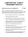
2 METER FM 5 WATT
TRANSMITTER KIT
Ramsey Electronics Model No.
FT146
Here's a simple hard-working transmitter that's ideal for
repeaters, Fox-hunts, remote bases, Packet - you name it! Why
tie up a whole transceiver to just use the transmitter? Fun and
educational to build - you'll be on-the-air in an evening!
•
Direct, true FM for excellent voice and data quality.
•
Both Data and mike audio inputs
•
Solid 5 watt RF output - add our PA-146 for 40 watts
•
Crystal controlled with 146.52 MHz crystal included
•
Built-in test points for easy tune-up. Align with any
digital multimeter - tuning tool included, too!
•
Runs on 12 - 14 Volts DC at less than 1 amp
•
Easy assembly and hook-up
•
Informative manual answers questions on theory, hookups and uses - enhances resale value, too!
•
Add our case set for a finished 'Pro' look. Cases match
all Ramsey products
•
Clear, concise assembly instruction carefully guides
you to a finished kit that works the FIRST time!
FT146 • 1
RAMSEY TRANSMITTER KITS
• FM10, FM-25 FM Stereo Transmitters
• TV6 Television Transmitter
• Cube TV Transmitters
RAMSEY RECEIVER KITS
• FR1 FM Broadcast Receiver
• AR1 Aircraft Band Receiver
• SR2 Shortwave Receiver
• AA7 Active Antenna
• SC1 Shortwave Converter
RAMSEY HOBBY KITS
• RB1 Rat Blaster Rodent Repeller
• SS70A Speech Scrambler
• TT1 Telephone Recorder
• WEB1 Walking Electronic Bug
• MD3 Microwave Motion Detector
• TFM3 Tri-Field Meter
• ECG1 Heart Monitor
RAMSEY AMATEUR RADIO KITS
• DDF1 Doppler Direction Finder
• HR Series HF All Mode Receivers
• QRP Series HF CW Transmitters
• FR146 2 Meter Receiver
• CPO3 Code Practice Oscillator
• QRP Power Amplifiers
RAMSEY MINI-KITS
Many other kits are available for hobby, school, Scouts and just plain FUN. New
kits are always under development. Write or call for our free Ramsey catalog.
FT146 FM RECEIVER KIT INSTRUCTION MANUAL
Ramsey Electronics publication NO. MFT146 Rev. 1.3
First printing: February 1992
COPYRIGHT 1992 by Ramsey Electronics, Inc. 590 Fishers Station Drive, Victor, New York
14564. All rights reserved. No portion of this publication may be copied or duplicated without the
written permission of Ramsey Electronics, Inc. Printed in the United States of America.
FT146 • 2
Ramsey Publication No. MFT146
Price $5.00
KIT ASSEMBLY
AND INSTRUCTION MANUAL FOR
FT146 FM RECEIVER
KIT
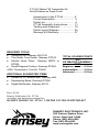
TABLE OF CONTENTS
Introduction to the FT146 ..............
Circuit Description .........................
Parts List ........................................
FT146 Assembly Instructions ........
Testing and Alignment ...................
Power Supply Considerations .......
Verifying RF Power Output............
Troubleshooting Guide ..................
Enclosure Ideas .............................
Microphone Considerations...........
Crystal Requirements ....................
Parts Layout Diagram ....................
Ramsey Kit Warranty.....................
4
5
6
8
19
21
21
23
24
24
25
26
27
RAMSEY ELECTRONICS, INC.
590 Fishers Station Drive
Victor, New York 14564
Phone (585) 924-4560
Fax (585) 924-4555
www.ramseykits.com
FT146 • 3
INTRODUCTION
Two meter FM has been around for years, but never with the popularity that
is enjoyed today. In the old days, hams snooped around the local two-way
radio shop in search of an obsolete taxi cab or police radio. These radios
were in the 150 - 174 MHz business band and were easily moved down into
the ham two meter band. On the chance that a UHF 450 - 470 MHz radio
was found, it was modified for the ham 440 band. Since there was no
business band near the 220 MHz ham band, no radios were available for
conversion - and that's why the 220 band never became popular!
Well, its been a long step from then to now, and not a pleasant one for ham
radio. We've lost a portion of our 220 band and gave up our ham radio
market to the Japanese. Gone are the radio mavens who could modify, in an
evening, the old Motorolas, GEs and RCAs. Modern day hams don't use
modified commercial radios, they operate rigs designed expressly for
amateur use, and who can blame them? For a half a kilobuck (that's $500 in
regular talk) you can get a full band synthesized 30 watt radio that looks like
a fine piece of audio gear! Good deal but something is missing, and that's the
pride in building, understanding and learning. You see it really doesn't take a
whole lot of smarts to unpack a box that was last sealed somewhere in the
Orient. Building your own rig is one of the most satisfying and rewarding
experiences you can have - and that's what ham radio is all about! This little,
easy to understand two meter FM transmitter is our attempt to provide the
ham community with a simple, fun to build kit that you'll enjoy operating,
especially when you tell the other operator that the rig here is home-brew.
Most Ramsey Electronics can be classified as "Skill Level 1" if we use the old
Heathkit guidelines for ease of assembly. That means that our kits are
intended to be successful for first-time kit builders. This FT146 FM
Transmitter is best regarded as a "Skill Level 2" project, (or least Level 1.46!)
and should not be taken lightly, even by experienced, licensed radio
amateurs.
Still, this step-by-step manual is written with the beginner in mind, because
we are well aware of the fascination Two Meters and its maze of repeaters
holds, which means this could be your very first kit project. To be honest,
we'd like to see first-time builders start out with an easier kit such as the
Ramsey HR-40 forty meter all-mode receiver before assembling the FT146,
but we are confident that you can construct the FT146 successfully if you
follow this manual carefully and patiently.
Before beginning the project or even studying the circuit description, it's
worthwhile to develop some prior respect for how much transmitter is packed
onto the circuit board. The dozen semiconductor devices (diodes, transistors
FT146 • 4
and IC chip) give the equivalent of about 130 or more transistors and diodes.
And, in addition to 13 inductors, a crystal and the various plus and jacks, there
are over 60 capacitors and resistors. Surely, all that should result in a decent
transmitter! You could easily spend twice the money plus hours of time trying to
gather the equivalent parts from catalogs and still need to make your own circuit
board.
FT146 CIRCUIT DESCRIPTION
Basic overview: The FT146 is a crystal controlled FM transmitter that uses a
varactor modulated crystal oscillator followed by a 9 times frequency multiplier
and power amplifier. Test points are built-in for easy alignment.
Detailed description: Transistor Q1 functions as a Colpitts crystal oscillator
whose frequency is determined by Y1 and varactor diode D1. Transistor Q2
functions as a buffer amplifier to isolate the crystal oscillator from other portions
of the circuit. The crystal oscillator frequency is multiplied by 3 (tripled) in
transistor Q3. Frequency multipliers are nothing more than amplifiers that
produce lots of distortion! In this case we're interested in having enough
distortion so that the third harmonic is fairly strong. We "pick-off" or filter the
third harmonic with a band pass filter, comprised of L9,13 and capacitors
C28,21,22,16. This allows transistor Q4 to be driven only by the third harmonic
of the crystal frequency - in this case, around 48 MHz. Q4 is another tripler,
multipling up the 48 MHz to 144 MHz. Inductors L5,11 and capacitors
C25,17,18,10 for the band pass filter for the three times output frequency.
From here on out, we're working at the actual carrier frequency and use a
couple of transistors to amplify the signal up to a 4 to 6 watt level. Transistor Q5
boosts the signal to the 250 mW range and Q6 then produces the full power
output. Impedances must be matched between stages to allow for maximum
power transfer, and that's the function of a couple of coils that are hand wound.
A low pass filter follows the final amplifier to limit out of band signals (remember
those multiplier stages?). Modulation is accomplished by varying the
capacitance of varactor diode, D1. This varying capacitance shifts the frequency
of the crystal ever so slightly causing a frequency shift, which is FM or
Frequency Modulation. And yes - this frequency shift does get multiplied as it
travels through the multiplier stages. The signal used to vary the varactor diode
is our desired audio modulation. Op-amp U1 functions as a microphone
amplifier, clipper and low pass filter. We clip the microphone signal to prevent
overmodulation and limit the maximum modulation frequency since either one
could cause our transmitter to "splash" into adjacent channels.
To make our transmitter compatible with standard ICOM/YAESU style
microphones we use transistor Q7, which senses when current is being drawn
by the microphone. When the mike is keyed, the current drawn turns on Q7
which applies bias to transistor Q1, allowing it to operate and thus the rig goes
FT146 • 5
into transmit. There is no need to control the voltage to any other transistors
since they all operate class "C". A class C amplifier draws no current unless it is
driven, so there is no need to switch the later stages on and off.
FT146 2 METER FM TRANSMITTER KIT PARTS LIST
Capacitors:
❒
❒
❒
❒
❒
❒
❒
❒
❒
❒
❒
❒
❒
❒
❒
❒
❒
1 2 or 2.2 pf disc capacitor (marked 2 or 2.2 or 2K or 2.2K) [C17]
1 4.7 or 5 pf disc capacitor (marked 4.7 or 5 or 4.7K or 5K) [C21]
2 10 pf disc capacitor (marked 10 or 10K) [C19,20]
1 12 pf disc capacitor (marked 12 or 12K) [C25]
1 15 pf disc capacitor (marked 15 or 15K) [C27]
1 22 pf disc capacitor (marked 22 or 22K) [C18]
3 39 pf disc capacitor (marked 39 or 39K) [C13,15,28]
2 47 pf disc capacitor (marked 47 or 47K) [C10,22]
1 56 pf disc capacitor (marked 56 or 56K) [C14]
6 100 pf disc capacitor (marked 100 or 101) [C6,11,16,24,26,29]
1 470 pf disc capacitor (marked 470 or 471) [C30]
13 .001 uf disc capacitor (marked .001 or 1000 or 102)
[C7,8,23,31,32,33,37,38,39,40,41,44,45]
6 .01 uf disc capacitor (marked .01 or 10 nf or 103) [C1,3,4,5,35,36]
1 .1 uf disc capacitor (marked .1 or 104) [C9]
2 10 uf electrolytic capacitor [C34,42]
1 100 to 220 uf electrolytic capacitor [C2]
2 Trimmer capacitor, 30 pf [C12,43]
Resistors and potentiometers:
❒
❒
❒
❒
❒
❒
❒
❒
❒
❒
❒
1
1
1
2
2
7
2
6
3
3
1
2 ohm resistor (red-black-gold) [R6]
51 ohm resistor (green-brown-black) [R10]
100 ohm resistor (brown-black-brown) [R28]
270 ohm resistor (red-violet-brown) [R8,20]
470 ohm resistor (yellow-violet-brown) [R7,25]
1 K ohm resistor (brown-black-red) [R1,2,4,9,11,22,29]
2.2 K ohm resistor (red-red-red) [R21,24]
10 K ohm resistor (brown-black-orange) [R12,15,16,23,26,27]
47 K ohm resistor (yellow-violet-orange) [R3,5,17]
100 K ohm resistor (brown-black-yellow) [R14,18,19]
5 K ohm potentiometer [R13]
FT146 • 6
Inductors and ferrite cores:
❒
❒
❒
❒
❒
2
2
2
2
2
Shielded can tunable inductor (marked 007007) [L9,13]
Tunable inductor (pink plastic body) [L5,11]
6 hole ferrite bead core [L1,6]
Small ferrite bead core [L10,12]
Aluminum coil shield cans [for L5,11]
Semiconductor devices:
❒
❒
❒
❒
❒
❒
1
2
1
1
2
1
❒
❒
❒
❒
❒
❒
1
1
1
1
1
1
1N4002 style black epoxy diode [D5]
1N4148 style signal diode (glass body with black band) [D2,4]
BB609 varactor diode (black body with yellow color band) [D1]
Zener diode, 6.2 volt (gray body with black band) [D3]
2N3904 NPN transistor (marked 2N3904) [Q1,2]
2SC2498 or 2SC2570A VHF/UHF NPN transistor (marked C2498 or
2570A) [Q3]
NE021 flat pack NPN transistor (marked 021) [Q4]
2N3866 metal can NPN transistor [Q5]
SD1127 metal can RF power transistor [Q6]
2N3906 style PNP transistor (marked 221334) [Q7]
LM358 dual op-amp IC chip [U1]
LED Light emitting diode [LED1]
Special components:
❒
❒
❒
❒
❒
❒
❒
❒
1
1
1
1
1
1
Crystal 16.280 MHz (for 146.520 MHz output) [Y1]
5 pin DIN connector [P1]
RCA style phono jack [J1]
2.5MM sub-miniature phono jack [J2]
Push-on aluminum heat sink
5/16" x 20 bolt (to wind coils on)
1 1/2 feet enameled magnet wire
1 1/2 feet tinned buss wire
Required, not supplied:
❒
❒
❒
❒
12 volt DC power source at 1 amp minimum
Microphone
Dummy load or suitable antenna
Enclosure such as the Ramsey CFT
FT146 • 7
RAMSEY Learn-As-You-Build KIT ASSEMBLY:
There are over 200 solder connections on the FT146 printed circuit board. That
means your work could be 99% perfect and you could STILL have 2 or 3 cold
solder points or solder bridges. Since this circuit is more sophisticated than a
direct-conversion HF receiver or a CW HF transmitter, a beginner or casual
amateur could have a harder time tracing a problem due to a poor solder
connection. Therefore, PLEASE take us seriously when we say that good
soldering is essential to the proper operation of your transmitter!
•
•
•
Use a 25-watt soldering pencil with a clean, sharp tip.
Use only rosin-core solder intended for electronics use.
Use bright lighting, a magnifying lamp or bench-style magnifier may be
helpful.
• Do your work in stages, taking breaks to check your work.
• Carefully brush away wire cuttings so they don't lodge between solder
connections.
We have a two-fold "strategy" for the order of the following kit assembly steps.
First, we install parts in physical relationship to each other, so there's minimal
chance of inserting wires into wrong holes. Second, whenever possible, we
install in an order that fits our "Learn-As-You Build" Kit building philosophy.
For each part, our word "Install" always means these steps:
1. Pick the correct part value to start with.
2. Insert it into the correct PC board location.
3. Orient it correctly, follow the PC board drawing and the written direc
tions for all parts - especially when there's a right way AND a
wrong way to solder it in. (Diode bands, electrolytic capacitor
polarity, transistor shapes, dotted or notched ends of IC's, and
so forth.)
4. Solder all connections unless directed otherwise. Use enough heat
and solder flow for clean, shiny, completed connections. Don't
be afraid of any pen-style soldering iron having enough heat to
damage a component.
5. Trim or "nip" the excess component lead wire after soldering.
NOTE: Save some of the longer wire scraps nipped from resistors and
capacitors. These will be used to form wire jumpers (JMP1, etc.) to be soldered
in just like parts during these construction steps.
Now, let's start building!
❒
1. Install J1, the RCA-style antenna jack. Solder all 4 points.
❒
2. Install P1, the 5 pin DIN jack.
FT146 • 8
❒
3. Install J2, the subminiature phone jack. Solder all three points. Be
gentle and patient in inserting, so as not to damage the solder tabs.
❒
4. Install R13, 5K trimmer pot. This is the modulation adjustment control.
❒
5. Install U1, LM358 op-amp IC chip. In installing the IC, you may wish to
use an 8-pin DIP socket rather than soldering the IC directly to the board.
Reasons for doing this might include the peace of mind of being able to
easily replace the IC if ever necessary. However, please be aware that we
have seen more service problems with improper socket insertion than from
soldering in IC's. Even if this is your first IC, don't be afraid to use enough
heat to make 8 clean connections, but DO be sure to orient the end marked
by a band or dot correctly. Before soldering, make sure that the IC or
socket is perfectly flat against the top of the PC board and that all pins are
properly in each PC board hole. This little 8 pin chip contains two separate
amplifiers and is used to amplify the microphone output and process the
audio for transmisssion.
❒
6. Install C39, .001 uf disc capacitor (marked .001, 1 nf or 102).
❒
7. Install C38, .001 uf disc capacitor (marked .001, 1 nf or 102).
❒
8. Install C36, .01 uf disc capacitor (marked .01 or 10 nf or 103).
❒
9. Install R14, 100K ohm (brown-black-yellow).
❒
10. Install R18, 100K ohm (brown-black-yellow).
❒
11. Install R19, 100K ohm (brown-black-yellow).
❒
12. Install C41, .001 uf disc capacitor (marked .001, 1 nf or 102).
❒
13. Install R20, 270 ohm (red-violet-brown).
❒
14. Install C42, 10 uf electrolytic capacitor. Electrolytic capacitors are
polarized with a (+) and a (-) lead and must be installed in the correct
orientation. Ordinarily, only the negative side is marked on the capacitor
body with a dark band and the (-) sign clearly shown, while PC boards will
usually show the (+) hole location. Use care to ensure proper polarity.
❒
15. Install JMP2, jumper wire. Use a piece of wire clipped from a previously
installed component bent into a small "U" or wire staple shape. Jumpers act
as electronic "bridges" carrying signals over PC board traces underneath.
❒
16. Install another wire jumper, JMP1.
❒
17. Install C34, 10 uf electrolytic capacitor. Remember to observe correct
polarity.
❒
18. Install C37, .001 uf disc capacitor (marked .001, 1 nf or 102).
❒
19. Install R17, 47 K ohm (yellow-violet-orange).
❒
20. Install C40, .001 disc capacitor (marked .001, 1 nf or 102).
FT146 • 9
❒
21. Install R15, 10K ohm (brown-black-orange).
❒
22. Install C33, .001 uf disc capacitor (marked .001, 1 nf or 102).
❒
23. Install R16, 10K ohm, (brown-black-orange).
Time for a breather and progress check. So far, we've built up the audio section
of our transmitter, from microphone amplifier to low pass filter to buffer stage not bad for less than an hour! Give a quick check to see that you've installed all
parts in the correct places and that all joints are soldered nicely with no
splashes or bridges.
❒
24. Install R24, 2.2K ohm (red-red-red).
❒
25. Install R23, 10K ohm (brown-black-orange).
❒
26. Identify Q7, a 2N3906 PNP transistor (marked 221334). Do not
confuse it with the other transistors in your kit. Position Q7's large flat side
as shown in the parts layout diagram. Press the transistor snugly into the
PC board so that only a minimum amount of wire lead is exposed above
the board. In soldering, do not be afraid of using enough heat to make a
good solid connection.
❒
27. Install R21, 2.2K ohm (red-red-red).
❒
28. Install C45, .001 uf (marked .001, 1 nf or 102).
❒
29. Install R25, 470 ohm (yellow-violet-brown).
❒
30. Install R11, 1K ohm (brown-black-red).
❒
31. Install R27, 10K ohm (brown-black-orange).
❒
32. Install R12, 10K ohm (brown-black-orange).
❒
33. Install D1, BB609 varactor diode (small black body with yellow band).
Varactor diodes act as voltage variable capacitors. In his case, D1's
capacitance is varied by the amplified voltage from your microphone,
causing the crystal oscillator's frequency to change - in exact step with your
voice. Voila, FM or Frequency Modulation!
❒
34. Install C35, .01 uf (marked .01 or 103 or 10 nf).
❒
35. Install C32, .001 uf disc capacitor (marked .001, 1 nf or 102).
❒
36. Install R26, 10K ohm (brown-black-orange).
❒
37. Install R5, 47K ohm (yellow-violet-orange).
❒
38. Install C24, 100 pf disc capacitor (marked 100 or 101).
❒
39. Install C30, 470 pf disc capacitor (marked 470 or 471).
❒
40. Install R8, 270 ohm (red-violet-brown).
FT146 • 10
❒
41. Install R7, 470 ohm (yellow-violet-brown).
❒
42. Identify Q1, a 2N3904 NPN transistor (marked 2N3904). Install Q1,
observing correct placement of the flat side.
❒
43. Install Q2, another 2N3904 NPN transistor (marked 2N3904).Observe
correct placement of the flat side.
❒
44. Install C27, 15 pf disc capacitor (marked 15 or 15K).
❒
45. Install trimmer capacitor, C43 (black body with orange top). This
trimmer is used for setting the FT146 exactly on frequency.
❒
46. Install Y1, crystal. This is the "heart" of the FM transmitter, producing
the initial signal which is multiplied and amplified up to the final transmitted
signal. Notice that there are two holes "kitty-corner" around Y1. These
holes are used to supply power to the optional crystal oven; they are not
used in the standard FT146 kit.
❒
47. Install D3, zener diode (gray body with black band). A zener diode
functions as a voltage regulator since it has the property of holding the
voltage across it constant. In this case we wish to hold the voltage to the
crystal oscillator steady to keep us on frequency, even with a poorly
regulated disc capacitor power supply.
❒
48. Install R28, 100 ohm (brown-black-brown).
❒
49. Install R1, 1K ohm (brown-black-red).
❒
50. Install JMP3, another wire jumper.
❒
51. Install C3, .01 uf (marked .01 or 103 or 10 nf).
❒
52. Install C9, .1 uf disc capacitor (marked .1 or 104).
❒
53. Install C23, .001 uf disc capacitor (marked .001, 1 nf or 102).
❒
54. Install C44, .001 uf disc capacitor (marked .001, 1 nf or 102).
❒
55. Install C8, .001 uf disc capacitor (marked .001, 1 nf or 102).
❒
56. Install C5, .01 uf disc capacitor (marked .01 or 10 nf or 103).
This completes assembly of the crystal oscillator section of our FM transmitter.
If so inclined, we could connect up some power and actually "fire-up" the PC
board so far. We'd only be producing a signal at 1/9 of the carrier frequency
though, since we've yet to build the multiplier stages.
❒
57. Install R3, 47K ohm (yellow-violet-orange).
❒
58. Install Q3, 2SC2498 or 2SC2570A NPN VHF transistor (marked C2498
or 2570A). Position the flat side as shown on the parts layout.
❒
59. Install C28, 39 pf disc capacitor (marked 39 or 39K).
FT146 • 11
❒
60. Install C21, 4.7 or 5 pf disc capacitor (marked 4.7 or 5 or 4.7K or 5K).
❒
61. Install L9, slug tuned shielded coil (marked 007007). This coil is part of
the first tripler section. It is tuned to the third harmonic of the crystal
oscillator.
❒
62. Install L13, another slug tuned shielded coil (marked 007007). This coil
is also part of the first tripler section.
❒
63. Install TP1. Select a 1K resistor, R9 (brown-black-red). Trim back one
lead wire to a length of inch. Bend this wire into a small loop as shown. This
loop will act as a convenient point to connect a test probe for tuning up your
transmitter. Insert the resistor into the PC board and hold it carefully while
you solder it to the board.
❒
64. Install R6, 2 ohm resistor (red-black-gold).
❒
65. Install C29, 100 pf disc capacitor (marked 100 or 101).
❒
66. Install C22, 47 pf disc capacitor (marked 47 or 47K).
❒
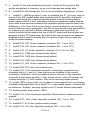
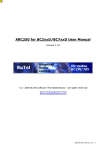
67. Locate Q4, NE021, the tiny black transistor disc stuck to a piece of
paper (marked 021). Carefully remove it from its protective paper and bend
all three leads down 90 degrees from its body. Notice how one lead is
longer than the others, that lead (the collector) must be installed exactly as
shown in the drawing - pointing towards L5. Set Q4 into the PC board
making sure that its body is snugly against the PC board and positioned
correctly. You should be able to read the
Test point loop
printed markings on the part, if you cannot,
then you have the transistor flipped over.
Resistor
PC board
Solder and trim all three leads.
❒
68. Install R4, 1K ohm (brown-black-red).
❒
69. Install C16, 100 pf disc capacitor (100 or 101).
❒
70. Install C25, 12 pf disc capacitor (marked 12 or 12K).
❒
71. Install L5, pink color slug tuned inductor. Make sure you place the coil
body right up against the PC board snugly.
❒
72. Install aluminum coil shield can cover
over L5.
Markings on this
side
❒
73. Install R10, 51 ohm (green-brownblack).
❒
74. Install C31, .001 uf disc capacitor
(marked .001 or 102).
❒
75. Install C17, 2 or 2.2 pf disc capacitor (marked 2 or 2.2).
021
K24
This lead towards
L5
Nine parts need handmade preparation before installation in the transmitter RF
FT146 • 12
stages of your transmitter. We recommend that you get them ready for
installation before assembling the Driver and Final stages. If you prefer to
proceed with those stages, winding coils as you go, that's fine, too, as long as
you realize that all coil making details are provided in this section.
The wire used for L1, 6, 10, and 12 is the smaller gauge enameled wire
supplied with your kit. We give you plenty but if you mess up, you can get a
whole 50' spool of it from Radio Shack (278-1341).
❒
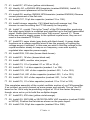
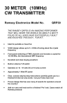
76. Winding L1 and L6 RF chokes (two identical units ): Examine the two
cylindrical ferrite cores provided in the kit.Notice that there are six holes at
either end of these cylinder shaped units, arranged in two groups of three.
Cut 6" of bus wire and following the drawing, thread the wire, pulling each
turn gently tight. Tin each end with solder by holding your soldering iron
and solder on the wire ends until the enamel insulation melts away and the
copper wire underneath coats nicely with solder. Tin all the way up to the
ferrite core body. Your finished RF chokes should look like this: Do not
install either part yet.
❒
77. Winding L10 and L12: Locate the two small black ferrite beads
provided in the kit. Cut 2" of enameled wire and following the drawing,
thread 3 turns through the bead hole, pulling each turn "gently tight." Tin
each end with solder. Tin all the way up to the ferrite core body. Your
finished bead chokes should look like this: Do not install either part yet.
❒
78. Winding L2 and L7: Use the heavy gauge tinned bus wire in your kit for
these coils. Wind these coils on the threads of the provided 5/16"X20 bolt
to assure perfect forming of the coils. (You wondered what that big bolt was
for - didn't you!) Both coils are 11/2 turns. They appear to be 2 turns if
viewed from the top. They will fit neatly into the PC board without any
excessive bending or stretching.
❒
79. Winding L3 and L4: Use the same wire and
procedure as used above for these coils. Each coil
is 2 1/2 turns and will appear to be 3 turns if
viewed from the top.
6 hole ferrite
core
enameled wire
tin ends
3 turns through
center
enameled wire
tin ends
FT146 • 13
FT146 • 14
FT146 • 15
The "legs" or leads for inserting L2, L7, L3 and L4 should be about " long.
These coils should sit about 1/8" maximum above the PC board when soldered.
❒
80. Install L12, one of the small 3 turn ferrite bead RF chokes you wound.
Pull it up snug against the PC board and solder.
❒
81. Install TP2, another test point. Select a 1K resistor, R2 (brown-blackred). Trim back one lead wire to a length of inch. Bend this wire into a
small loop as shown. This loop acts as a convenient point to connect a test
probe for tuning up your transmitter. Insert the resistor into the PC board
and hold it carefully while you solder it to
Test point loop
the board.
❒
82. Install C18, 22 pf disc capacitor
(marked 22 or 22K).
❒
83. Install C10, 47 pf disc capacitor (marked 47 or 47K).
❒
84. Install Q5, 2N3866 metal can RF transistor. Be sure you press the
transistor case flush against the PC board and solder securely.
❒
85. Install L6, a 6 hole ferrite bead choke wound previously.
❒
86. Install C4, .01 uf disc capacitor (marked .01 or 10 nf or 103).
❒
87. Install L11, pink slug tuned coil.
❒
88. Install aluminum shield can cover over L11.
❒
89. Install C19, 10 pf disc capacitor (marked 10 or 10K).
❒
90. Install C20, another 10 pf disc capacitor.
❒
91. Install L7, a 1 turn coil wound previously. Ensure that the coil is seated
flush against the PC board and not mounted with long leads up in the air which would add undesired additional inductance.
❒
92. Install C11, 100 pf disc capacitor (marked 100 or 101).
❒
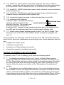
93. Prepare a inch long wire jumper from the heavy tinned bus wire used
for winding coils previously. Install this jumper in the L8 location on the PC
board. This wire must sit flat against the PC board and not up above.
Believe it or not, this wire is actually an inductor providing inpedance
matching into Q6.
❒
94. Install C26, 100 pf disc
capacitor (marked 100 or 101). Heavy buss
❒
95. Install L10, small ferrite
bead RF choke you wound
earlier.
❒
96. Install C6, 100 pf disc
capacitor (marked 100 or 101).
Resistor
PC board
wire jumper
Wire sits flat
against board
1/2 inch
PC board
(not a scrap component lead)
FT146 • 16
❒
97. Install D4, 1N4148 style signal diode (glass body with black band).
Observe correct orientation of the banded end.
❒
98. Install TP3, the last test point. Select a 1K resistor, R29 (brown-blackred). Trim back one lead wire to a length of inch. Bend this wire into a small
loop as before. Insert the resistor into the PC board and hold it carefully
while you solder it to the board.
❒
99. Install R22, 1K ohm (brown-black-red).
❒
100. Install C15, 39 pf disc capacitor (marked 39 or 39K).
❒
101. Install L4, 2 turn coil wound previously. Be sure it sits flush against the
PC board.
❒
102. Install C14, 56 pf disc capacitor (marked 56 or 56K).
❒
103. Install L3, another 2 turn coil. Be sure it sits flush against the PC board.
❒
104. Install C13, 39 pf disc capacitor (marked 39 or 39K).
❒
105. Install C7, .001 uf disc capacitor (marked .001 or 1000 or 102).
❒
106. Install C12, trimmer capacitor (black body with orange top).
❒
107. Install L2, 1 turn coil wound previously. Ensure it sits flush.
❒
108. Install L1, 6 hole ferrite bead RF choke you wound.
❒
109. Install C1, .01 uf disc capacitor (marked .01 or 103 or 10 nf).
❒
110. Locate Q6, SD1127 RF power transistor. This transistor mounts
somewhat differently from all the other parts. Turn over the PC board and
set the transistor snugly into the large hole and bend the leads over and into
the indicated holes. The leads should be as short as possible without
shorting against the transistor case. Solder the three transistor leads. See
drawing in the step below.
❒
111. Now we call for something unusual - soldering the transistor case to the
PC board. Run a neat "flow" of solder around the transistor case to the PC
board ground plane. The SD1127 Solder can to PC
board
power transistor is designed by
Solder side of
the manufacturer to be soldered
board
directly to a PC board ground
Component side of
plane for heat sinking and proper
b
d
VHF performance. This part is different from other metal can transistors in
that the case is connected internally to the emitter rather than the collector.
This provides much higher gain at VHF frequencies.
FT146 • 17
❒
112. Install C2, 100 to 220 uf electrolytic capacitor. Be sure to observe
polarity - especially with this part since it is directly across the power supply
and if reversed, could overheat so fast, so much that it could explode!
❒
113. Install D5, 1N4002 style black epoxy diode, observe correct orientation
of the banded end.
❒
114. Install D2, 1N4148 style signal diode (glass body with black band).
Observe correct orientation of the banded end.
❒
115. Locate the aluminum press on heat sink and slip it on to Q6.
❒
116. Install the LED transmit
indicator, LED1. Correctly identify the
Short lead here
cathode side lead which is the
Leave leads long
R13
shorter of the two. The shorter lead
goes into the hole nearest R13.
Install the LED, leaving full lead length extending above the board so that
the LED can be positioned later into the front panel indicator hole.
❒
117. Install a wire jumper between points A and C on the PC board. This
allows the use of an Icom/Yaesu/Radio Shack microphone plugged into
jack J2.
This completes our assembly of the FT146 two meter FM transmitter. Now's a
good time to give your masterpiece a good going over, being especially alert for
any:
• bridged over solder joints,
• misplaced components,
• transistors or diodes placed incorrectly,
• electrolytic capacitors installed incorrectly.
TESTING, ALIGNMENT AND ADJUSTMENT
To prepare your FT146 for testing, you'll need the following items:
❒
1. A suitable microphone of the Icom, Yaesu or Radio Shack variety.
Other microphones may be used providing you mate them correctly to the
FT146. Since there are such a wide variety of microphone types and styles,
we cannot provide exact hook-up wiring for every case. Hook-up is very
simple, follow the basic instructions in the "Microphone Considerations"
section.
❒
2. A hexagonal, non-metallic alignment tool. If you do not already have a
set of plastic or nylon coil alignment tools and do expect to build more ham
radio or electronic hobby projects, such tools are worth having and can be
found inexpensively at any electronics store including Radio Shack. While a
metal Hex key wrench will fit the coil slug, the metal itself will detune the
FT146 • 18
coil drastically whenever it is inserted into the coil. You may use a metal
hex key if you are aware of this effect and are willing to remove the hex
key from the coil after each adjustment. Although not recommended, with a
little patience and sandpaper, a useable tool may be formed from a piece of
wood or plastic rod. If you do make your own tool, be very careful to fully
engage the slug because they are very brittle and any wedging or skewed
turning will break it!
❒
3. Small flat blade screwdriver or alignment tool for trimmer capacitors
C12, C43, and modulation pot R13.
❒
4. A suitable 50 ohm dummy load.
❒
5. Proper cable to connect from FT146 transmitter (RCA phono) to
dummy load.
❒
6. A 12 volt DC power source of at least 1 amp.
❒
7. A digital multimeter.
With all the above set-up and handy, let's get testing!
❒
1. Using your hex head tuning tool, back out the coil slugs in L9, L13, L5,
L11 even with the top of their plastic coil form. If a slug binds, gently rock it
back and forth till it loosens up. Be very careful not to crack the slug as
they are brittle. Slowly rotate each slug clockwise into the coil form the
indicated number of turns:
L9: 2 turns
L13: 3 turns
L5: 8 turns
L11: 4 turns
❒
2. Rotate modulation control R13 fully counter-clockwise.
❒
3. Apply 12 volts to the FT146 transmitter board. Its a good idea to fuse
the power to the FT146, 1 to 2 amps will do.
❒
4. Connect a proper 50 ohm dummy load to antenna connector J1. In a
pinch, a light bulb may be used - see the section "Verifying Transmitter RF
Power Output".
❒
5. Plug the microphone into mike jack J2. If you have no microphone, you
may at least "key" the transmitter by jumpering the "PTT" point behind DIN
jack P1 to ground.
❒
6. Hook your multimeter to TP1 and set the meter to the 200 mVDC, (0.2
VDC range).
❒
7. Key the microphone and adjust L9 and L13 for maximum indication on
TP1. No more than a turn or two is needed. You will have to go back and
forth between these coils as they interact. You should get a reading of at
least 50 mV.
FT146 • 19
❒
8. Move your meter probe over to TP2, key the transmitter and adjust L5
and L11 for maximum negative reading. Once again, go back and forth
between the two coils. You should get a reading of at least -120 mV. It is
very important to tune for the best peak as this will ensure proper
transmitter operation.
❒
9. You should now be able to see RF power at the output antenna jack,
J1. Adjust capacitor C12 for maximum RF power output.
❒
10. Slightly spread or compress coils L3 and L4 to maximize output power.
Power should be at least 4 watts with a 12 volt power source.
❒
11. While speaking into the microphone, slowly rotate modulation control
R13 clockwise for best sounding modulation. Ideally, a two-way radio
service monitor should be used to adjust this control.
❒
12. If a frequency counter or service monitor is available, adjust capacitor
C43 for exactly 146.520 MHz. If you do not have such equipment, use a
receiver with a center tune meter.
This completes the alignment of your FT146. The PC board should be mounted
into a protective enclosure to guard against accidental contact. The Ramsey
CFT case set provides an ideal, perfectly sized and matched case for your
FT146. Study the following sections regarding the DC power supply and RF
power indication, and operate your transmitter in accord with good amateur
radio practice.
YOUR POWER SUPPLY AND RF OUTPUT POWER
For optimum performance, one or two volts of extra DC supply power can make
quite a difference in any transmitter. For example, two lantern batteries in
series, or 8 "D cells" will obviously provide "about 12 volts" with sufficient
current capability for casual operating. For maximum RF output power, use a
supply of 13 to 14 volts DC. The easiest method is to place two fresh "D cells"
in series with your power source, if a full 13.6-15 volts DC is not available. A
word of caution concerning wall plug style AC adapter power supplies: They are
not suitable for operation of your transmitter due to their poor regulation, AC
ripple content and RFI suseptibility.
If your supply voltage is in the 11-12 volt range, you can expect a 600 to 800
ma current flow and about 4 watts of the RF output power. With a solid 13 to 14
volt supply, you can expect about 1 amp current draw and up to 5 or 6 watts of
RF output power.
VERIFYING TRANSMITTER RF OUTPUT
The most important thing to know is whether your transmitter is delivering some
measurable and reassuring level of RF power to the antenna. The sound of the
FT146 • 20
transmitter keying in a receiver is of some help, but even the simplest crystal
oscillator can send a fine signal into your neighbor's receiver.
Ideally, you have a small RF wattmeter, already inserted in the antenna line,
capable of accurately measuring low output power in watts. And it cost you less
than what you paid for the transmitter kit. Right? In the words of Wayne from
"Wayne's World"... Not! So here are a few other ideas for you to try.
Saying the same thing another way, we assume you know that accurate,
commercially built RF wattmeters cost much more than what you paid for this
Ramsey transmitter kit.
Since this solid-state transmitter does not require lots of critical tuning or
adjustments, a periodic power output check-up should suffice. If you do not own
or have access to a low-level RF power meter, use a trick that is decades old,
the common flashlight or panel bulb. All you need to know is the basic
differences between bright, superbright, dim, unlit and burned out! Using a light
bulb to check power output is also a satisfying way to put Ohm's Law to work.
Your Radio Shack catalog specifies operating voltage and current in
milliamperes for a variety of small replacement lamps. It may be worth your
while to make up a simple plug-in "output tester" for your transmitter, a male
RCA plug connected to a socket for the bulb of your choice or even soldered
directly to the bulb. RF voltage levels in this transmitter can vary from 2 to 25
volts RMS depending on various factors. Typically, 1 watt power levels are
achieved in 5 to 7 volts RMS volts range, and 5 watts at 15 to 20 volts. A good
test bulb for this level is the PR-4 flange-style flashlight bulb or the type 243
bulb with screw-in body. Both are rated to give normal brilliance at 2.33 volts,
drawing 270 milliamps of current. Using Ohm's law, P=IE, we see that normal
brilliance requires 2.33 volts x .270 amperes for .62 watts of DC power
consumption. We can conclude that even a watt or so of RF should light this
bulb reasonably well. A type PR-12 bulb is suitable for checking RF outputs in
the 1-3 watt range. Try it out!
Please remember, though, that a flashlight bulb does NOT present the proper
load impedance to the transmitter output, so theoretical calculations based on
the bulb`s rating can only be approximate. For example, the PR-4 at full
brilliance presents only an 8.2 ohm load to the transmitter. Because of this, the
transmitter may act "flakey" when tuning up into a light bulb, and by all means
you should not consider a light bulb an accurate indicator of the FT146's
performance!
If ANY flashlight bulb lights up when connected to the antenna jack of this
transmitter, you can be satisfied that you have RF output power at least equal
to the DC power rating of the bulb you are using. If you burn out your bulb,
rejoice and put your rig on the air!
FT146 • 21
Amateur radio magazines and handbooks provide a variety of circuits for RF
wattmeters and relative field-strength indicators, including methods of using
your VOM as an indicating device. CQ magazine for March 1990 offers an
article by KB4ZGC on how to make a highly accurate yet inexpensive dummy
load and wattmeter capable of showing 1/10-watt differences in RF power. If
you use a wattmeter characterized for the HF frequency region, it will not give
accurate results at the much higher two meter frequencies, although it will be
quite adequate for go/no-go testing.
MAXIMIZING RF POWER OUTPUT
The simplest way to ensure maximum reasonable power output without
component damage is to run the DC voltage in the 13 to 14 volt range,
observing a maximum limit of +15VDC. Typically, an automobile power source
is 13.6 volts when the engine is running and most mobile rigs are specified at
this voltage level.
IMPORTANT NOTE: If you are experimenting with this transmitter and see a
sudden and massive increase in power output and DC current, you have not
reached the promised land or created a 25 watt transmitter! Sudden surges like
that are a sure sign of amplifier self-oscillation. Kill the DC power supply
immediately, because your Q6 RF power transistor is heading to selfdestruction while probably interfering with every TV set in the neighborhood! A
poorly matched antenna along with higher supply voltages is usually
responsible for this occuring. Any prolonged "parasitic" emissions may also
overheat and destroy other components in the amplifier stages.
TROUBLESHOOTING HINTS
The transmitter is very easy to troubleshoot, providing you use some simple
common sense. If you cannot get any readings on the test points or RF power
output, check and see if the crystal oscillator is running - how? Well, take a look
at the crystal and see the frequency marked on it, it should be 16.280 MHz (1/9
of 146.52 MHz), right in the middle of the HF shortwave broadcast band, easily
received on any shortwave radio. You should be able to "hear" the oscillator
running quite easily.
If crystal oscillator operation is confirmed, let's move on a step further. The
oscillator is followed by a tripler stage, and 3 times 16.280 MHz is 48.840 MHz.
Once again this signal can be tuned on a nearby receiver such as a scanner.
One more tripler follows and that moves us up to the final 146.520 MHz output
frequency, easily tuned on a two meter rig. This proceedure will lead us to the
final amplifier stages where we can pretty much do a thourough visual
inspection.
Common problems to look for are solder bridges or interchanged capacitors FT146 • 22
"hum-m-m-, that's not a .001 uf where a 100 pf should be is it?"
If there is a problem in getting the modulation working, a scope or audio
amplifier will allow tracing down any problem in short order. The microphone
audio is amplifier by about 350 times in U1:B. You should see at least a volt of
audio at the output (pin 7) of U1:B. A low pass filter follows U1:B, you should
still see at least a volt of audio at pin1 of U1. From there, the audio drives the
varactor diode D1.
How about keying of the transmitter? Check to be sure that the microphone is
switching to ground when keyed. This closure to ground causes PNP transistor
Q7 to turn on, switching +12 volts to its collector. This +12 volts lights the LED
and applies bias to the crystal oscillator.
If you hear a AC hum on the transmitted signal, usual causes are RF getting
back into the power supply or a bad VSWR on the antenna.
These short checks in no way detail any and all problems that can rear their
ugly head, but should get you on the way to solving most errors. We'd like to be
able to forsee a problem a builder may encounter, but the sheer number of
parts and the permutations and combinations of installing them makes an list of
precise, exact solutions impossible. If you run into a roadblock, gather all your
thoughts and information and give a call to the factory for some help. If you
elect to enlist the help of a local expert, great - but be sure the expert is
qualified - no need for having someone lead you down the wrong path!
Remember you may always return the kit for factory service, and there's no
charge if the problem is our fault. See the warranty on the last page of this
manual.
MICROPHONE CONSIDERATIONS
During assembly, the FT146 was jumpered for using an Icom style microphone
plugged into the mike jack J2. You may also use the rear panel 5 pin DIN jack,
P1. If you decide to do so, change the "Audio In" wire jumper to go between A
and B. When this is done, the transmitter cannot be keyed from the microphone
and must be keyed from the PTT pin.
FT146 • 23
Here's a handy reference chart for the 5 pin DIN jack
PIN #
FUNCTION
1
+12 VDC power input
2
Power ground
3
Audio input
4
Audio ground
5
PTT (Push-To-Talk)
Audio level required is in the 10 to 50 mV range. PTT requires a path to ground
of less than 10K ohms.
OTHER ENCLOSURE RECOMMENDATIONS
Your finished transmitter can be installed in a variety of enclosures of your own
design and choosing. You might be planning to combine several Ramsey circuit
boards in a single enclosure. Use of the inexpensive and attractive Ramsey
case set will give your unit that finished look and increase its resale value.
These sturdy black instrument cases are supplied with neatly-lettered front and
rear panels, rubber feet and mounting screws.
While we believe that the Ramsey enclosure option is a fine value for finishing
off your Ramsey kit transmitter, we're happy to give you a couple of additional
suggestions and our reasons for them. If your first goal is economy and rugged
portability, you will find that the circuit board can be mounted nicely in a
standard VHS videotape storage box, which also gives room for additional
microphone, power and antenna connectors, and even a small mike. The
connectors are easily mounted at one end of such a box. It may be necessary
to cut away the molded posts which secure the tape cassette itself. These
storage boxes come in several styles, so pick one that looks truly practical as a
project enclosure.
If you wish to accomplish RF shielding, the most economical metal enclosure
nicely suited for Ramsey amateur kit boards is Radio Shack No. 270-253A.
This metal utility cabinet can accommodate both a receiver and transmitter
board, plus speaker, with room for various refinements you might like to add.
CRYSTAL REQUIREMENTS
The FT146 transmitter uses a crystal at 1/9 the final carrier output frequency.
This is a fairly common type of crystal that is found in many of the older "rockbound" rigs that populate many hamfest flea market tables. You may order
additional crystals from JAN Crystal, 1-800-JAN-XTAL, specify HC-18/U holder,
wire leads, parallel resonant, 18 pf load capacitance.
FT146 • 24
NOTE ON REPLACEMENT PARTS:
If you lose or damage parts during assembly or testing, you may, of course,
order any needed replacement parts by writing or faxing the Ramsey
Electronics, Inc. factory. Some of the more common parts may also be picked up
at Radio Shack or other local parts distributors. Use EXACT values when
replacing parts. The following is a general guide to obtaining parts for your
transceiver as quickly as possible:
[A]: Radio Shack or local electronic parts distributor: Resistors, electrolytic
capacitors, disc capacitors, common NPN or PNP transistors, zener diodes,
switching diodes, hookup wire, LED, controls, antenna and microphone
connectors.
[B]: Order from RAMSEY ELECTRONICS: Most RF and VHF transistors, coils,
crystals, PIN diodes, varactor diodes, trimmers, IC chips.
[C]: U1 is a common dual op-amp made by many manufacturers and is
commonly stocked by most parts stores. There are also acceptable "standard
replacements" for some of the semiconductors used in the transmitter. "SK" and
"ECG" standard replacements are stocked by local electronics parts distributors
or may be ordered through a Radio Shack store. The following chart should help
you make the most cost-effective choice if replacement semiconductors are
needed. Performance of your transmitter will, in most cases, not be up to full
spec if you decide to use a relacement device, but will get you by in a pinch.
Part ID
Type
Q1, etc.
Q12,13,14
Q2, etc.
Q3
Q9
Q8
D
D3,D23
D18
D11,D12
U1
2N3904
PNP 221334
2SC2498
NE021
2N3866
SD1127
1N4148
BB505
1N4002
6.2 V zener
LM358
Recommended source
RE=Ramsey, RS=Radio Shack
RS 276-1617
RS276-1604 or 2N3906
ECG10, SK9139, 2N5179, or RE
MRF901 or RE
ECG311, SK3195 or RE
MRF237, ECG341, SK9617 or RE
1N914, RS276-1620 (pack of 50)
RE
RS276-1102, 1N4003
RS276-561
ECG928, SK3691 or RE
FT146 • 25
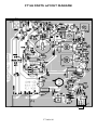
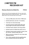
FT146 PARTS LAYOUT DIAGRAM
FT146 • 26
The Ramsey Kit Warranty
Please read carefully BEFORE calling or writing in about your kit. Most
problems can be solved without contacting the factory.
Notice that this is not a "fine print" warranty. We want you to understand your rights and ours too! All
Ramsey kits will work if assembled properly. The very fact that your kit includes this new manual is
your assurance that a team of knowledgeable people have field-tested several "copies" of this kit
straight from the Ramsey Inventory. If you need help, please read through your manual carefully, all
information required to properly build and test your kit is contained within the pages!
1. DEFECTIVE PARTS: It's always easy to blame a part for a problem in your kit, Before you conclude
that a part may be bad, thoroughly check your work. Today's semiconductors and passive components
have reached incredibly high reliability levels, and it’s sad to say that our human construction skills
have not! But on rare occasions a sour component can slip through. All our kit parts carry the Ramsey
Electronics Warranty that they are free from defects for a full ninety (90) days from the date of
purchase. Defective parts will be replaced promptly at our expense. If you suspect any part to be
defective, please mail it to our factory for testing and replacement. Please send only the defective part
(s), not the entire kit. The part(s) MUST be returned to us in suitable condition for testing. Please be
aware that testing can usually determine if the part was truly defective or damaged by assembly or
usage. Don't be afraid of telling us that you 'blew-it', we're all human and in most cases, replacement
parts are very reasonably priced.
2. MISSING PARTS: Before assuming a part value is incorrect, check the parts listing carefully to see
if it is a critical value such as a specific coil or IC, or whether a RANGE of values is suitable (such as
"100 to 500 uF"). Often times, common sense will solve a mysterious missing part problem. If you're
missing five 10K ohm resistors and received five extra 1K resistors, you can pretty much be assured
that the '1K ohm' resistors are actually the 'missing' 10 K parts ("Hum-m-m, I guess the 'red' band
really does look orange!") Ramsey Electronics project kits are packed with pride in the USA. If you
believe we packed an incorrect part or omitted a part clearly indicated in your assembly manual as
supplied with the basic kit by Ramsey, please write or call us with information on the part you need
and proof of kit purchase
3. FACTORY REPAIR OF ASSEMBLED KITS:
To qualify for Ramsey Electronics factory repair, kits MUST:
1. NOT be assembled with acid core solder or flux.
2. NOT be modified in any manner.
3. BE returned in fully-assembled form, not partially assembled.
4. BE accompanied by the proper repair fee. No repair will be undertaken until we have received the
MINIMUM repair fee (1/2 hour labor) of $25.00, or authorization to charge it to your credit card
account.
5. INCLUDE a description of the problem and legible return address. DO NOT send a separate letter;
include all correspondence with the unit. Please do not include your own hardware such as
non-Ramsey cabinets, knobs, cables, external battery packs and the like. Ramsey
Electronics, Inc., reserves the right to refuse repair on ANY item in which we find excessive
problems or damage due to construction methods. To assist customers in such situations,
Ramsey Electronics, Inc., reserves the right to solve their needs on a case-by-case basis.
The repair is $50.00 per hour, regardless of the cost of the kit. Please understand that our technicians
are not volunteers and that set-up, testing, diagnosis, repair and repacking and paperwork can take
nearly an hour of paid employee time on even a simple kit. Of course, if we find that a part was
defective in manufacture, there will be no charge to repair your kit (But please realize that our
technicians know the difference between a defective part and parts burned out or damaged through
improper use or assembly).
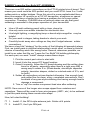
4. REFUNDS: You are given ten (10) days to examine our products. If you are not satisfied, you may
return your unassembled kit with all the parts and instructions and proof of purchase to the factory for
a full refund. The return package should be packed securely. Insurance is recommended. Please do
not cause needless delays, read all information carefully.
FT146 • 27
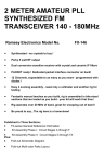
FT146 2 Meter FM Transmitter Kit
Quick Reference Page Guide
Introduction to the FT146 ..............
Circuit Description..........................
Parts List ........................................
FT146 Assembly Instructions ........
Testing and Alignment ...................
Parts Layout Diagram ....................
Ramsey Kit Warranty .....................
REQUIRED TOOLS
• Soldering Iron Ramsey WLC100
• Thin Rosin Core Solder Ramsey RTS12
• Needle Nose Pliers Ramsey MPP4 or
RTS05
• Small Diagonal Cutters Ramsey RTS04
<OR> Technician’s Tool Kit TK405
4
5
6
11
19
26
27
TOTAL SOLDER POINTS
232
ESTIMATED ASSEMBLY
TIME
Beginner............... 6.8 hrs
Intermediate ......... 3.9 hrs
Advanced ............. 2.9 hrs
ADDITIONAL SUGGESTED ITEMS
• Holder for PC Board/Parts Ramsey HH3
• Desoldering Braid Ramsey RTS08
• Digital Multimeter Ramsey M133
Price: $5.00
Ramsey Publication No. FT146
Assembly and Instruction manual for:
RAMSEY MODEL NO. FT146 2 METER FM TRANSMITTER KIT
RAMSEY ELECTRONICS, INC.
590 Fishers Station Drive
Victor, New York 14564
Phone (585) 924-4560
FT146 • 28
Fax (585) 924-4555
www.ramseykits.com