1
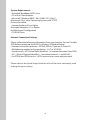
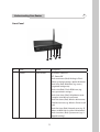
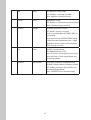
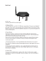
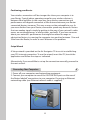
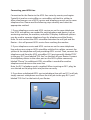
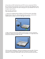
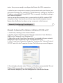
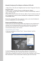
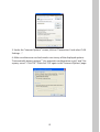
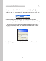
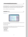
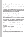
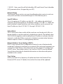
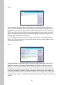
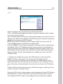
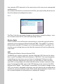
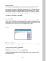
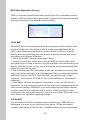
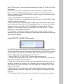
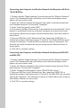
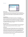
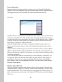
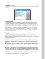
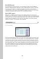
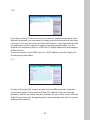
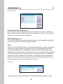
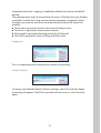
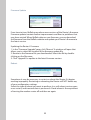
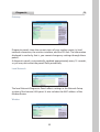
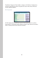
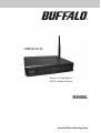
WBMR-G125
Wireless-G High Speed
ADSL2+ Modem Router
MANUAL
www.buffalo-technology.com
Table of Contents
1 Introduction
Product Features Benefits of a Home Network
Advantages of a Buffalo Wireless Network
Package Contents
System Requirements
Internet Connection Settings 1
1
3
3
4
4
4
2 Understanding your Router
5
3 Connecting your Computers
8
4 Manually Configuring Client Adapters
11
5 Accessing the User Interface
14
6 Understanding the Web-Based User Interface
15
7 Internet/LAN
15
8 Wireless Config
19
9 Security
27
10 Gaming Ports
28
11 Admin Config
30
12 Diagnostic
33
13 EU - Declaration of Conformity
35
1
Introduction
Thank you for purchasing the Buffalo ADSL2+ Wireless- G Modem Router. In
minutes you will be able to share your Internet connection and network your
computers with your new Router. The following is a list of features that make
your Router an ideal solution for your home or small office network. Please be
sure to read through this User Manual completely.
Product Features
OS Compatibility
The Router supports a variety of operating environments including
Windows® 98SE, Me, 2000, XP and Vista. You will need an Internet browser
and a network adapter that supports TCP/IP (the standard language of the
Internet).
Front-Panel LED Display
Lighted LEDs on the front of the Router indicate which functions are in
operation. You’ll know at-a-glance whether your Router is connected to the
Internet. This feature eliminates the need for advanced software and statusmonitoring procedures.
Web-Based Advanced User Interface
You can set up the Router’s advanced functions easily through your web
browser, without having to install additional software onto the computer.
There are no disks to install or keep track of and, best of all, you can make
changes and perform setup functions from any computer on the network
quickly and easily.
Integrated 10/100 4-Port Switch
The Router has a built-in, 4-port network switch to allow your wired
computers to share printers, data and music files, digital photos, and much
more. The switch features automatic detection so it will adjust to the speed of
connected devices. The switch will transfer data between computers and the
Internet simultaneously without interrupting or consuming resources.
Integrated 802.11g Wireless Access Point
802.11g is an exciting new wireless technology that achieves data rates up to
54Mbps, nearly five times faster than 802.11b.
125 High-Speed Mode
High-Speed Mode (HSM)*, a 54g™ performance enhancement, provides
the fastest wireless connectivity for 802.11g-capable networks in real-world
environments. It is designed for home networks that require additional
bandwidth for applications such as sharing digital pictures. 125HSM makes
802.11g WLANs more efficient without impacting the performance of
neighboring networks, and it is compatible at high speeds with leading
brands.
Built-In Dynamic Host Configuration Protocol (DHCP)
Built-In Dynamic Host Configuration Protocol (DHCP) on-board makes for
the easiest possible connection of a network. The DHCP server will assign
IP addresses to each computer automatically so there is no need for a
complicated networking setup.
SPI Firewall
Your Router is equipped with a firewall that will protect your network from a
wide array of common hacker attacks.
Universal Plug-and-Play (UPnP) Compatibility
UPnP (Universal Plug-and-Play) is a technology that offers seamless operation
of voice messaging, video messaging, games, and other applications that are
UPnP-compliant.
Support for VPN Pass-Through
If you connect to your office network from home using a VPN connection,
your Router will allow your VPN-equipped computer to pass through the
Router and to your office network.
*When operating in High-Speed Mode, this Wi-Fi® device may achieve an
actual throughput of up to or greater than 34.1Mbps, which is the equivalent
throughput of a system following 802.11g protocol and operating at a
signaling rate of 125Mbps. Actual throughput will vary depending on
environmental, operational, and other factors.
Benefits of a Home Network
By following our simple setup instructions, you will be able to use your
Buffalo home network to:
• Share one high-speed Internet connection with all the computers in your
home
• Share resources, such as files, and hard drives among all the connected
computers in your home
• Share documents, music, video, and digital pictures
• Store, retrieve, and copy files from one computer to another
• Simultaneously play games online, check Internet email, and chat
Advantages of a Buffalo Wireless Network
Mobility – you’ll no longer need a dedicated “computer room”— now you
can work on a networked laptop or desktop computer anywhere within your
wireless range
Easy Setup – Buffalo's Easy Installation Wizard makes setup simple
Flexibility – set up and access printers, computers, and other networking
devices from anywhere in your home
No cabling required – you can spare the expense and hassle of retrofitting
Ethernet cabling throughout the home or office
Package Contents
• Wireless-G High Speed ADSL2+ Modem Router (WBMR-G125)
• Utility CD-ROM w/ User Manual
• Quick Setup Guide
• AC Adapter
• Ethernet Cable
• DSL Cable
• Warranty Statement
System Requirements
• Activated Broadband ADSL Line
• PC with a Client Adapter
• Microsoft® Windows 98SE / Me / 2000 / XP / Vista™,
Macintosh OS or other Operating System with TCP/IP
Protocol Installed
• Internet Explorer 5.0 or higher
Netscape Navigator 4.7 or higher
for Web-based Configuration
• CD-ROM Drive
Internet Connection Settings
Please collect the following information from your Internet Service Provider
(ISP) before setting up the ADSL2+ Wireless-G Modem Router.
• Internet connection protocol - (PPPoE, PPPoA, Dynamic IP, Static IP)
• Multiplexing method or Encapsulation - (LLC or VC MUX)
• Virtual circuit - VPI (Virtual Path Identifier) - (a number between 0 and 255)
• VCI - (Virtual Channel Identifier) - (a number between 1 and 65535)
• For PPPoE and PPPoA users - ADSL account user name and password
Please refer to the Quick Setup Guide for a list of the most commonly used
settings for your country.
2
Understanding Your Router
Front Panel
1 2
3 5
4 6
No
Name
Colour
Description
1
POWER
Green or Red
ON (Green): Power On
OFF : Power Off
Blinks continuous (Red): Writing in FlashROM (e.g. change settings, update firmware)
Blinks once (Red): RAM error (e.g. access,
recognized storage size)
Blinks twice (Red): Flash-ROM error (e.g.
access, parameter settings)
Blinks three times (Red): Wired device error
(Example: wired driver install error)
Blinks four times (Red): Wireless device error,
Wired device error (e.g. Wireless Driver install
error)
Blinks five times (Red): Network error (e.g. IP
address at WAN side is within LAN network)
Blinks nine times (Red): System error (e.g. it
stopped working)
2
LAN
Green
ON: LAN Port is ready (LINK)
OFF: LAN Port is not ready (no LINK)
Blinks: LAN Port is communicating
3
Wireless
Green
ON: Wireless is valid
OFF : Wireless is invalid/cannot communicate
Blinks: Communicating wirelessly
4
SECURITY
Orange
ON: Wireless Security is active
OFF: Wireless Security is inactive
Blinks twice: Waiting for AOSS/WPS (PBC) to
be activated.
Blinks continuously: AOSS/WPS (PBC) setup
is failed (timeout/negotiation error – it keps
blinking for 30 mins, then it will turn off the
LED if security is not set.)
5
DSL
Green
ON: DSL is synchronizing
OFF: Modem function is off
Series of 2 blinks: Searching for carrier signal
Series of 4 blinks: Carrier signal found, and
connecting modem.
6
INTERNET
Green or Red
ON (Green): IP Address at WAN obtained
ON (Red): Failed to obtain IP Address at WAN
OFF : Modem function is off, or ADSL is not
connected. (Bridge Mode)
Blinks: INTERNET port is communicating
Back Panel
7
8 9
6
6. DSL Line
Connect your ADSL line to this port.
7. Ethernet Ports
The Ethernet ports are RJ45, 10/100 auto-negotiation. The ports are labeled 1
through 4. These ports correspond to the numbered LEDs on the front of the
Router. Connect your network-enabled computers or any networking devices
to one of these ports.
8. Reset Button
The “Reset” button is used in rare cases when the Router may function
improperly. Resetting the Router will restore the Router’s normal operation
while maintaining the programmed settings.
You can also restore the factory default settings by using the Reset button.
Use the restore option in instances where you may have forgotten your
custom password.
a. Resetting the Router - Push and hold the Reset button for one second
then release it. When the Power/Ready light becomes solid again, the reset is
complete.
b. Restoring the Factory Defaults - Press and hold the Reset button for 10
seconds then release it. When the Power/Ready light becomes solid again,
the restore is complete.
9. Power Plug
Connect the included power supply to this inlet. Use the power supply
provided as using the wrong type of power adapter may cause damage to
your Router.
Positioning your Router
Your wireless connection will be stronger the closer your computer is to
your Router. Typical indoor operating range for your wireless devices is
between 30m and 60m. In the same way, your wireless connection and
performance will degrade somewhat as the distance between your Router
connected devices increases. This may or may not be noticeable to you. As
you move farther from your Router, connection speed may decrease. Factors
that can weaken signals simply by getting in the way of your network’s radio
waves are metal appliances, or obstructions, and walls. If you have concerns
about your network’s performance that might be related to range or
obstruction factors, try moving the computer to a position between 1.5m and
3.0m from the Router, in order to see if distance is the problem.
Setup Wizard
A Setup wizard is provided on the Air Navigator CD to assist in establishing
your DSL internet connection. To use the wizard, insert the CD, launch the
application and follow the steps as indicated.
Alternatively, if you would like to set up the connection manually, proceed to
the next section.
3
Connecting Your Computers
1. Power off your computers and networking equipment.
2. Connect your computer to one of the YELLOW RJ45 ports on the rear of
the Router labeled “connections to your computers” by using an Ethernet
networking cable (one Ethernet network cable is supplied).
Connecting your ADSL Line
Connection for the Router to the ADSL line varies by country and region.
Typically it involves a microfilter or a microfilter with built-in splitter to
allow simultaneous use of ADSL service and telephone service on the same
telephone line. Please read the following steps carefully and select the
appropriate method.
1. If your telephone service and ADSL service are on the same telephone
line, ADSL microfilters are needed for each telephone and device, such as
answering machine, fax machine, and caller ID display. Additional splitters
may be used to separate telephone lines for telephone and the Router.
Note: Do not connect the ADSL microfilter between the wall jack and the
Router—this will prevent ADSL service from reaching the modem.
2. If your telephone service and ADSL service are on the same telephone
line and you are using an ADSL microfilter with built-in splitter, connect the
splitter to the telephone wall jack providing ADSL service. Then, connect the
telephone cord from the ADSL microfilter RJ11 port generally labeled “DSL”
to the gray RJ11 port labeled “DSL line” on the back of your Router. Connect
the telephony device to the other port on the ADSL splitter commonly
labeled “Phone”. An additional ADSL microfilter is needed for another
telephone and device on the same line.
Note: An RJ11 telephone cord is supplied. When inserting an RJ11 plug, be
sure the tab on the plug clicks into position correctly.
3. If you have a dedicated ADSL service telephone line with an RJ11 wall jack,
simply connect a telephone cord from the wall jack to the gray RJ11 port
labeled “DSL line” on the back of your Router.
4. If you have an RJ45 wall jack for your ADSL service, connect an RJ45-toRJ11 converter to the wall jack. Then connect one end of the telephone cord
to the converter and the other end to the gray RJ11 port labeled “DSL line” on
the back of your Router.
Powering Up your Router
1. Connect the supplied power adapter to the Router power-input plug
labeled “Power”. Note: For safety and performance reasons, only use the
supplied power adapter to prevent damage to the Router.
2. After connecting the power adapter and the power source is turned on,
the Router’s power icon on the front panel should be on. It might take a few
minutes for the Router to fully start up.
3. Turn on your computer(s). After your computer(s) boot up, the LAN status
LED on the front of the Router will be on for each port to which a wired
computer is connected. These lights show you the connection and activity
10
status. Now you are ready to configure the Router for ADSL connection.
In order for your computer to properly communicate with your Router, you
will need to change your computer’s “TCP/IP Ethernet” settings to “Obtain an
IP address automatically/Using DHCP”. This is normally the default setting in
most home computers.
You can set up the computer that is connected to the ADSL modem FIRST
using these steps. You can also use these steps to add computers to your
Router after the Router has been set up to connect to the Internet.
Manually Configuring Client Adapters
4
Manually Configuring Client Adapters in Windows XP, 2000, or NT
1. Click “Start”, “Settings”, then “Control Panel”.
2. Double-click on the “Network and dial-up connections” icon (Windows
2000) or the “Network” icon (Windows XP).
3. Right-click on the “Local Area Connection” associated with your network
adapter and select “Properties” from the drop-down menu.
4. In the “Local Area Connection Properties” window, click “Internet Protocol
(TCP/IP)” and click the “Properties” button. The following screen will appear:
5. If not already selected, select “Obtain an IP address automatically” (1) and
“Obtain DNS server address automatically” (3). Click “OK”.
Your network adapter(s) are now configured for use with the Router.
11
Manually Configuring Client Adapters in Windows 98SE or Me
1. Right-click on “My Network Neighborhood” and select “Properties” from the
drop-down menu.
2. Select “TCP/IP -> settings” for your installed network adapter.
3. If not already selected, select “Obtain an IP address automatically” on the IP
address tab. Click “OK”.
4. You will also need to delete the Gateway address from the Gateway tab and
DNS Configuration entries in order to properly be configured for connection
to the Buffalo router.
Restart the computer. When the computer restarts, your network adapter(s)
are now configured for use with the Router.
Recommended Web Browser Settings
In most cases, you will not need to make any changes to your web browser’s
settings. If you are having trouble accessing the Internet or the advanced
web-based user interface, then change your browser’s settings to the
recommended settings in this section.
Internet Explorer 4.0 or Higher
1. Start your web browser. Select “Tools” , “Internet Options” and the
"Connections" tab.
2. In the “Connections” tab, there are three selections: “Never dial a
connection”, “Dial whenever a network connection is not present”, and
“Always dial my default connection”. If you can make a selection, select “Never
dial a connection”. If you cannot make a selection, go to the next step.
12
3. Under the “Internet Options” screen, click on “Connections” and select “LAN
Settings…”.
4. Make sure there are no check marks next to any of the displayed options:
“Automatically detect settings”, “Use automatic configuration script”, and “Use
a proxy server”. Click “OK”. Then click “OK” again in the “Internet Options” page.
13
5
Accessing the User Interface
1. You can access the web-based management user interface of the Router
using the Internet browser on a computer connected to the Router. Type
“http://192.168.11.1” in your browser’s address bar. Then press the “Enter” key.
Note: It is strongly recommended that you use a computer physically
connected to the Router with an RJ45 cable for initial setup. Using a wirelessly
connected computer for initial setup is not recommended.
2. The following screen will appear in your browser to prompt you to log in.
The default User Name is “Root” and the default Password is blank. Click on
the “OK” button to log in.
Note: It is strongly recommended that you set a password for increased
security.
14
������������������������������������������
Understanding the Web-Based User Interface
6
Quick-Navigation Tabs - You can go directly to any of the Router’s UI pages
by clicking directly on these links. The links are divided into logical categories
and grouped by tabs to make finding a particular setting easier to find.
Help is available to the right of each page.
7
Internet/Lan
INTERNET/LAN
The “Internet/LAN” tab is where you will set up your Router to connect to your
Internet Service Provider.
Connection Type
From the “Connection Type” page, you can select one of these five connection
types based on the instruction provided by your ISP:
• RFC 2516 PPPoE
• RFC 2364 PPPoA
• 1483 Bridged
• 1483 Routed
• Bridge Mode Only
15
Setting your ISP Connection Type to PPPoE or PPPoA
PPPoE (Point-to-Point Protocol over Ethernet) is the standard method of connecting networked devices. It requires a user name and password to access
the network of your ISP for connecting to the Internet. PPPoA (PPP over ATM)
is similar to PPPoE, but is mostly implemented in the UK. Select PPPoE or PPPoA and then set the following options:
1. Multiplexing - Select as supplied by your ISP. VC-MUX: PPPoA Virtual Circuit
Multiplexer (null encapsulation) allows only one protocol running per virtual
circuit with fewer overheads. LLC: PPPoA Logical Link Control allows multiple
protocols running over one virtual circuit (more overhead).
2.Virtual Circuit - Enter your Virtual Path Identifier (VPI) and Virtual Circuit
Identifier (VCI) parameter here. (Assigned by your ISP).
3. User Name - Enter the user name. (Assigned by your ISP).
4. Password - Enter your password. (Assigned by your ISP).
5. Connect on Demand - Click this option if you want your Modem Router to
connect to your ISP when a connection is needed, and to disconnect when
the line to your ISP has been idle for a given amount of time. Connection and
disconnection are automatic. You can also adjust the maximum idle time; the
default setting is 20 minutes.
6. Keep Alive - Click this option if you want to maintain the connnection to
your ISP all the time. If the link goes down for a given number of seconds (the
“redial period”), the Modem Router will automatically try to re-establish it.
The default redial period is 20 seconds.
Setting your Connection Type to RFC 1483 Bridged/Routed
This connection method bridges your network and your ISP’s network
together. The Router will obtain an IP address automatically from your ISP’s
DHCP server.
1. Multiplexing - Select LLC or VC MUX.
2. VPI/VCI - Enter your Virtual Path Identifier (VPI) and Virtual Circuit Identifier
(VCI) parameters here. These identifiers are assigned by your ISP.
Setting your Connection Type to Bridge Mode Only (Disable Internet Sharing)
In this mode, the Router simply acts as a bridge passing packets across the
DSL port. It requires additional software to be installed on your computers in
order to access the Internet.
16
1. VPI/VCI - Enter your Virtual Path Identifier (VPI) and Virtual Circuit Identifier
(VCI) parameter here. (Assigned by your ISP).
Network Setup
The Network Setup section sets your broadband modem router to work correctly with machines connected through its LAN (Ethernet) ports.
Local IP Address
This is the gateway’s IP address on the LAN — the address by which local
machines contact the gateway. The default setting is 192.168.11.1. When this
and the default subnet mask are used, other machines on the network can
have IP addresses from 192.168.11.2 through 192.168.11.254.
Subnet Mask
This is a four-part value used by all the machines on the physical LAN to indicate whether or not the network is divided into subnets. The default value,
255.255.255.0 (together with the default local IP address), indicates that the
network is undivided. When a network is divided, communication between
subnets requires routers or similar gateway devices.
Network Address Server Settings (DHCP)
DHCP is the Dynamic Host Configuration Protocol, a way of automatically
assigning IP settings to machines on a network. Most personal computers are
set to act as DHCP clients; when they boot up, they request IP settings from
a DHCP server. The modem router is set to act as a DHCP server by default.
Consult the online help for detailed information on the advanced options
available in this section.
Time Setting
Select your time zone, frequency of update and enter the Network Time
Protocol (NTP) server’s IP address from which the time will be updated.
17
DDNS
If your Modem Router’s Internet IP address is assigned dynamically and
you wish to host a Web site or other Internet service, you can sign up with
DynDNS.org or TZO.com for Dynamic DNS (DDNS) service. Then select your
DDNS provider from this list box, enter the required information, and click
Apply. The gateway will send its Internet IP address to the provider so the
provider can update your DNS entry.
For DynDNS.org service, you must enter a user name, password, and host
name. For TZO.com service, you must fill in the correct e-mail address, password, and domain name.
Route
Network Address Translation (NAT) lets you use “private” (and cost-free) IP
addresses on your LAN and a single “public” IP address (which you must
pay for) on the Internet. When a local computer accesses the Internet, your
broadband modem router changes the source address from the computer’s
to its own Internet IP address. When a response comes back, it changes the
destination address from its Internet IP address to the requesting computer’s
local IP address. NAT is enabled (turned on) by default. Disable it if you do not
need it.
18
8
Wireless Config
AOSS
AOSS™ (AirStation One-Touch Secure System) Connection
AOSS is a Buffalo technology that makes it simple to connect wireless clients
to an access point securely.
You no longer need to worry about choosing the proper security protocols, IP
addresses, or SSID’s. The intelligence of AOSS determines the best connection
possible and configures itself in seconds.
NOTE: Your wireless client device must support AOSS for this to work. All
current Buffalo wireless client devices support AOSS.
Once the WBMR-G125 has been connected, install your wireless client device
(Notebook, USB, or PCI Adapter) and any necessary drivers and software. If
your client device comes with Client Manager Software, please install it. The
AOSS button will be located in this software. Now that the Wireless Modem
Router and your wireless client adapter are installed, you can use AOSS to
configure them.
1. To begin the configuration, press the AOSS button on the front of the
WBMR-G125 for 3 -10 seconds. The Security LED will begin to flash.
2. Now, push the AOSS button on the client device. Depending on which
device you have, this may be either on the device, or in its software. Consult
your client device’s documentation if you don’t know where its AOSS button
is.
3. When AOSS has finished, the Security LED will change to a solid state. Your
wireless network is securely set up!
Only one AOSS wireless client adapter can be configured to the AOSS Wireless
Modem Router at a time. The buttons will need to be repressed to connect
each additional AOSS wireless client adapter.Do not attempt to configure
19
two separate AOSS networks at the same time, as this may cause unexpected
configurations.
If an undesired client has connected via AOSS, you may forcibly disconnect it
from the advanced configuration menu.
Basic
The “Basic” tab lets you make changes to the wireless network settings - wireless network name (SSID), radio and operating channel.
Wireless Radio
Select Disable to turn off wireless networking, or select the type of wireless
network you are setting up: Mixed (with both 802.11b and 802.11g clients),
B-Only (with only 802.11b clients), or G-Only (with only 802.11g clients). Using the correct setting here ensures that the network will work as efficiently
as possible.
SSID
Changing the Wireless Network Name (SSID)
To identify your wireless network, a name called the SSID (Service Set Identifier) is used. The default SSID of the Router is “BUFFALO”. You can change this
to anything you want to or you can leave it unchanged. If there are other
wireless networks operating in your area, you will want to make sure that
your SSID is unique (does not match that of another wireless network in the
area). To change the SSID, type in the SSID that you want to use in the SSID
field and click “Apply” . The change is immediate. If you make a change to the
SSID, your wireless-equipped computers may also need to be reconfigured to
connect to your new network name. Refer to the documentation of your wireless network adapter for information on making this change.
20
Wireless Channel
Your Router is configured to operate on the proper channels for the country
you reside in. If there are other wireless networks operating in your area,
your network should be set to operate on a channel that is different than the
other wireless networks. For best performance, use a channel that is at least
five channels away from the other wireless networks. For instance, if another
network is operating on channel 11, then set your network to channel 6 or
below. To change the channel, select the channel from the drop-down list.
Click “Apply”. The change is immediate.
Broadcast SSID
For security purposes, you can choose not to broadcast your network’s SSID
(set to “Allow” by default). Doing so will keep your network name hidden from
computers that are scanning for the presence of wireless networks. To turn off
the broadcast of the SSID, remove the tick and click on “Apply”.
Security
Wireless Authentication
When Security Mode is set to Open, wireless transmissions are not encrypted,
and the network can be compromised.
Three encryption methods are available:
Wired Equivalent Privacy (WEP).
Wi-Fi Protected Access Pre-shared Key (WPA-PSK),
Wi-Fi Protected Access Pre-shared Key (WPA2-PSK)
Choose a setting that can be used by all the wireless devices that will link to
the Modem Router.
21
WEP (Wired Equivalent Privacy)
WEP is a common protocol that adds security to all Wi-Fi-compliant wireless
products. WEP was designed to give wireless networks the equivalent level of
privacy protection as a comparable wired network.
64-Bit WEP
64-bit WEP was first introduced with 64-bit encryption, which includes a key
length of 40 bits plus 24 additional bits of system-generated data (64 bits
total). Some hardware manufacturers refer to 64-bit as 40-bit encryption.
Shortly after the technology was introduced, researchers found that 64-bit
encryption was too easy to decode.
1. Select “64-bit WEP” from the drop-down menu.
2. Default Transmit Key - When you use 64-bit WEP, you can set up to four
encryption keys. As long as the keys are identical and in the same order on all
devices, each device can use any one of the four to encrypt transmitted data.
Specify the transmit key here.
3. After selecting your WEP encryption mode, you can enter your key by typing in the hex key manually. A hex (hexadecimal) key is a mixture of numbers
and letters from A–F and 0–9. For 64-bit WEP, you need to enter 10 hex
characters, (For instance: AF 0F 4B C3 D4 = 64-bit WEP key) or 10 keyboard
characters.
4. Click “Apply” to finish. Encryption in the Router is now set. Each of your
computers on your wireless network will now need to be configured with the
same security settings. WARNING: If you are configuring the Wireless Router
or access point from a computer with a wireless client, you will lose your
connection until you enable security on your wireless client. Please be sure to
write down your key before applying changes
128-Bit WEP
As a result of 64-bit WEP’s potential security weaknesses, 128Bit WEP was
developed as a more secure method of encryption. 128-bit encryption
includes a key length of 104 bits plus 24 additional bits of system-generated
22
data (128 bits total). Some hardware manufacturers refer to 128-bit as 104-bit
encryption.
Most of the new wireless equipment in the market today supports both
64-bit and 128-bit WEP encryption, but you might have older equipment
that only supports 64-bit WEP. All Buffalo wireless products will support both
64-bit and 128-bit WEP.
1. Select “128-bit WEP” from the drop-down menu.
2. Default Transmit Key - Specify the transmit key here. For 128-bit WEP, make
sure this control is set to key 1.
3. After selecting your WEP encryption mode, you can enter your key by typing in the hex key manually. A hex (hexadecimal) key is a mixture of numbers
and letters from A–F and 0–9. For 128-bit WEP, you need to enter 26 hex
characters, (For instance:C3 03 0F AF 0F 4B B2 C3 D4 4B C3 D4 E7 = 128-bit
WEP key), or 13 keyboard characters.
4. Click “Apply” to finish. Encryption in the Router is now set. Each of your
computers on your wireless network will now need to be configured with the
same security settings.
Setting WPA-PSK or WPA2-PSK Encryption
For WPA-PSK, all devices must use the same Encryption setting, either TKIP or
AES, and all clients must use the option selected here. For WPA2-PSK, you can
set Encryption to AES or to “TKIP or AES.” TKIP is the Temporal Key Integrity
Protocol; AES is the Advanced Encryption Standard.
1. Select “WPA-PSK” or “WPA2-PSK” from the drop-down menu.
2. For Encryption Technique, select “TKIP” or “AES”. For WPA2-PSK, you can set
Encryption to AES or to “TKIP or AES.”
3. Enter your Pre-Shared key. This can be from eight to 63 characters and can
be letters, numbers, or symbols. This same key must be used on all of the clients that you set up. For example, your PSK might be something like: “Smith
family network key”.
4. Rekey Interval - The actual keys used are derived from the pre-shared key,
and periodically “renewed” (changed). You can adjust the renewal interval if
you wish.
5. Click “Apply” to finish. You must now set all clients to match these settings.
23
Connecting your Computer to a Wireless Network that Requires a 64-Bit or
128-Bit WEP Key
1. Double-click the “Signal Indicator” icon to bring up the “Wireless Network”
screen. The “Advanced” button will allow you to view and configure more
options of your wireless card.
2. Under the “Wireless Network Properties” tab, select a network name from
the “Available networks” list and click “Configure”.
3. Under “Data Encryption” select “WEP”.
4. Ensure the check box “Network key is provided for me automatically” at the
bottom is unchecked. If you are using this computer to connect to a corporate network, please consult your network administrator if this box needs to
be checked.
5. Type your WEP key in the “Network key” box. Important: A WEP key is a
mixture of numbers and letters from A–F and 0–9. For 128-bit WEP, you need
to enter 26 characters. For 64-bit WEP, you need to enter 10 characters. This
Network key needs to match the key you assign to your Wireless Router or
access point.
6. Click “OK” to save the settings.
Connecting your Computer to a Wireless Network that Requires WPA-PSK
or WPA2-PSK
1. Double-click the “Signal Indicator” icon to bring up the “Wireless Network”
screen. The “Advanced” button will allow you to view and configure more
options of your wireless card.
2. Under the “Wireless Networks” tab, select a network name from the “Available networks” list and click “Configure”.
3. Under “Network Authentication” select “WPA-PSK (No Server)”.
4. Type your WPA key in the “Network key” box. Important: WPA-PSK is a
mixture of numbers and letters from A–Z and 0–9. For WPA-PSK you can enter
eight to 63 characters. This Network key needs to match the key you assign to
your Wireless Router or access point.
5. Click “OK” to save the settings.
24
Advanced
Multicast Rate
This is the transmission speed used when the Modem Router transmits to
multiple clients at the same time. Multicasting is common in applications that
involve audio and/or video streams. The default setting, Auto, usually gives
the best results, but a fixed, high rate may be preferable in some environments.
Frame Bursting
Choose the Frame Bursting mode. You can select “125* High Speed
Mode”.”Frame Bursting” or “Disable”. Frame Bursting is a technology that improves the transmission rate by sending frames seamlessly.125* High Speed
Mode is an advanced frame bursting mode with even higher throughput. To
function at their highest speeds, both of these technologies require clients
that support and are set up to use the same mode.125* High Speed Mode is
recommended. Default setting is “Disable”.
802.11g Protection
The default setting of Auto for this control helps to preserve the performance
of 802.11g clients in an environment of mixed 802.11 client types. The Off
setting is recommended only for an 802.11g-only environment.
DTIM Period
To coordinate the network, the Modem Router sends out “beacon frames,”
normally one every tenth of a second. A beacon frame can include a Delivery
Traffic Indication Message (DTIM). Clients in power-saving mode deactivate
their receivers except to receive beacon frames containing DTIMs, which
tell them if there is data for them to receive. The default DTIM period is 1,
meaning that every beacon frame contains a DTIM; a setting of 2 puts a DTIM
into every other beacon frame, and so on. Setting DTIM higher helps clients
conserve power but can reduce throughput.
25
Privacy Separator
Communication between wireless stations must go through the Modem
Router. The Privacy Separator function prevents any wireless station from accessing any other. You can enable this function for better security.
Mac Filter
The MAC Filter is a powerful security feature that allows you to specify which
computers are allowed on the network. Any computer attempting to access
the network that is not specified in the filter list will be denied access. Default
setting is “Allow All” which permits all wireless clients with the correct SSID
and security settings to join the network.
Click the “Registration List” button to display the MAC Address Filter List.
This is a list of wireless devices that will not be allowed to join the wireless
network.
To put a device on the list, you must know its Medium Access Control (MAC)
address, often called its MAC or LAN MAC. This normally can be found on a
label on the bottom or back of the device, or on the network interface card in
a desktop computer.
You can enter MAC addresses manually, or use the Wireless Client MAC List
(see below). When the desired MAC addresses are entered, click “Apply” to
save the list. A success message will appear. Click Continue, wait for the
MAC Address Filter List to reappear, and click Close to return to the Wireless
Network Access panel.
Wireless Client MAC List
Click this button to auto-detect wireless clients in the vicinity. For each, the
computer name, IP address, and MAC address are displayed, as well as a box
marked Enable MAC Filter. Click Refresh to scan again for wireless clients. To
block a client, put a check mark in its Enable MAC Filter box and click Update
Filter List.
26
9
Security
Firewall
VPN Passthrough
Virtual Private Network (VPN) passthrough lets authorised remote clients
log onto VPN servers on your LAN and join the LAN as though they were
locally connected. Strong encryption is normally used to make the remote
link secure. Your broadband gateway is set by default to allow four types of
VPN connections: IP Security (IPSec), Point-to-Point Protocol over Ethernet
(PPPoE), Point-to-Point Tunneling Protocol (PPTP), and Layer 2 Tunneling
Protocol (L2TP). You can leave passthrough of each enabled, or disable it,
according to your needs.
Firewall
Several kinds of additional dangers and annoyances can be blocked by
putting a check in the corresponding check box.
◘ Proxy servers on the Internet are sometimes used by attackers to hide their
location and identity.
◘ Cookies are records that some Web sites place on a user’s computer and
read back when the user again visits the site. They usually contain viewing
preferences, but they can also contain a user’s browsing or purchasing history.
◘ Java applets are small programs sent by Web sites and run under the control of a browser. They run in their own windows, and can potentially access
local disks and network connections.
◘ ActiveX is a programming language for Microsoft Windows that, like Java,
is used by some Web sites to create animated and interactive content. These
“ActiveX controls” also can potentially access local disks and network connections.
Some Web sites rely heavily on cookies, Java, or ActiveX, and may be partially
or completely inaccessible if any of these are blocked.
27
Block WAN Requests
An “anonymous Internet request” is an attempt to “ping” your broadband
gateway’s WAN interface. Pinging is a way of checking if a system is running
at a particular IP address. It can also be used to hunt for certain kinds of
vulnerabilities in the system. Blocking WAN requests means not responding
to pings coming from the Internet. This is the default setting.
Reject IDENT requests
When this is enabled, the AirStation sends reject packets if it receives an
IDENT request. The default is enabled. Use this filter when the communication
speed goes down using a network application like e-mail, ftp or WEB. If IDENT
requests are forwarded to a LAN side client by address translation setting
(DMZ or TCP port:113), this basic rule is ignored.
10
Gaming Ports
Port Forwarding
Port Forwarding allows you to route external (Internet) calls for services such
as a web server (port 80), FTP server (Port 21), or other applications, through
your Router to your internal network. Since your internal computers are protected by a firewall, machines from the Internet cannot get to them because
they cannot be “seen”. If you need to configure the port forwarding function
for a specific application, you will need to contact the application vendor
to find out which port settings you need. You can manually input this port
information into the Router.
28
DMZ
If you have a client PC that cannot run an Internet application properly from
behind the firewall, you can open the client up to unrestricted two-way Internet access. This may be necessary if the NAT feature is causing problems with
an application such as a game or video conferencing application. Use this
feature on a temporary basis as a DMZ host is highly exposed to the dangers
of the Internet
To put a computer in the DMZ, enter its LAN IP address and click “Apply” for
the change to take effect.
QoS
Quality of Service (QoS) assigns priority levels to different kinds of packets
to minimize delays in the transfer of data. The table lists five common applications and lets you enter the port numbers for up to three more. Click the
High Priority button for the application(s) whose packets you wish to receive
preferential treatment.
29
11
Admin Config
Management
Gateway Username & Password
This is the user name and password you must type to log onto your broadband modem router as administrator. The default user name is the word root
and there is no password set by default.
Remote Management
This control determines whether you can log onto and manage the gateway
from the Internet. The default setting is Disable.
UPnP
UPnP (Universal Plug-and-Play) is a technology that offers seamless operation
of voice messaging, video messaging, games, and other applications that
are UPnP-compliant. Some applications require the Router’s firewall to be
configured in a specific way to operate properly. This usually requires opening
TCP and UDP ports, and in some instances, setting trigger ports. An application that is UPnP compliant has the ability to communicate with the Router,
basically “telling” the Router which way it needs the firewall configured. It is
enabled by default, but can be disabled if you wish.
Reporting
The Log setting controls whether your broadband gateway keeps records
30
of operational events. Logging is enabled by default, but can be disabled if
desired.
The gateway keeps logs of several kinds of events. Clicking View Logs displays
a window in which these logs can be viewed separately or together. Select
the log(s) you want to view from the drop-down list box at the top of the
window.
◘ The System Log records the last start-up and similar events.
◘ The Access Log records Internet access events.
◘ The Firewall Log records blocking actions by the firewall.
◘ The UPnP Log records Universal Plug-and-Play events.
Diagnostics
This is a simple ping test to determine network connectivity.
Factory Defaults
To restore your Moedm Router’s factory settings, select Yes and click Apply.
A warning will appear. Click OK to proceed with the reset, or click Cancel to
abort.
31
Firmware Update
From time to time, Buffalo may release new versions of the Router’s firmware.
Firmware updates contain feature improvements and fixes to problems that
may have existed. When Buffalo releases new firmware, you can download
the firmware from the Buffalo website and update your Router’s firmware to
the latest version.
Updating the Router’s Firmware
1. In the “Firmware Upgrade” page, click “Browse”. A window will open that
allows you to select the location of the firmware update file.
2. Browse to the firmware file you downloaded. Select the file by doubleclicking on the file name.
3. Click “Upgrade” to update to the latest firmware version.
Reboot
Sometimes it may be necessary to restart or reboot the Router if it begins
working improperly. Restarting or rebooting the Router will NOT delete any
of your configuration settings.
Select the type of reboot you want to perform. In a soft reboot, various processes restart, and transient data is preserved. A hard reboot is the equivalent
of turning the modem router off and then on again.
32
12
Diagnostic
Gateway
Diagnostic panels show the current status of your modem router, its local
network connection, the wireless interface, and the DSL link. The information
displayed is read-only, that is, you cannot change any settings through these
panels.
A diagnostic panel is automatically updated approximately every 15 seconds,
so you may notice that the panels flash periodically.
Local Network
The local Network Diagnostic Panel reflects settings in the Network Setup
section of the Internet/LAN panel. It also includes the MAC address of the
Modem Router.
Wireless
33
The Wireless Diagnostic Panel reflects settings in the Wireless Configuration
tab’s Basic and Security panels. this panel also shows the wireless firmware
version and MAC address.
DSL Connection
If a DSL link has been established, technical information about it is shown
here. The PVC Connection section reflects settings in the Internet Connection
and VC Settings areas of the Internet/LAN panel.
34
13
EU - Declaration of Conformity
This device complies with the essential requirements of the R&TTE Directive
1999/5/EC.
The following test methods have been applied in order to prove presumption
of compliance with the R&TTE Directive 1999/5/EC:
• EN 60950: 2000
Safety of Information Technology Equipment
• EN 300 328-2 V1.2.1 (2001-12)
Technical requirements for spread-spectrum radio equipment
• EN 301 489-17 V1.1.1 (2000-09)
EMC requirements for spread-spectrum radio equipment
Taiwan:
SAR compliance has been established in typical laptop computer(s) with
CardBus slot, and product could be used in typical laptop computer with
CardBus slot. Other application like handheld PC or similar device has not
been verified, may not comply with related RF exposure rules, and such use
shall be prohibited.
Safety
This equipment is designed with the utmost care for the safety of those who
install and use it. However, special attention must be paid to the dangers of
electric shock and static electricity when working with electrical equipment.
All guidelines of this manual and of the computer manufacturer must therefore be allowed at all times to ensure the safe use of the equipment.
Intended use:
This device is a 2.4 GHz wireless LAN transceiver, intended for indoor home
and offi ce use in USA, Canada, all EU and EFTA member states.
EU Countries intended for use:
This device is intended for indoor home and offi ce use in the following
countries:
Austria, Belgium, Germany, Denmark, Spain, Greece, France, Finland, Italy,
Ireland, Luxembourg, The Netherlands, Portugal, Sweden, United Kingdom,
Cyprus, Czech Republic, Estonia, Hungry, Latvia, Lithuania, Malta, Poland,
Slovak Republic and Slovenia.
The device is also authorised for use in all EFTA member states Iceland,
Liechtenstein,Norway and Switzerland.
EU countries not intended for use:
35
None
Potential restrictive use:
This device is a 2.4 GHz wireless LAN transceiver, intended for indoor home
and office use in all EU and EFTA member states, except in France, Belgium
and Italy where restrictive use applies.
In Italy the end-user should apply for a license at the national spectrum
authorities in order to obtain an authorization to use the device for setting up
outdoor radio links.
In Belgium there is a restriction in outdoor use. The frequency range in which
outdoor operation in Belgium is permitted is 2460 – 2483.5 MHz.
In France only channels 10,11,12 and 13 are available.
This device may not be used for setting up outdoor radio links in France. For
more information see http://www.anfr.fr/ and/or http://www.art-telecom.fr
Warranty Information
Buffalo wireless products come with a 2-year limited warranty from the date
of purchase. Buffalo Technology warrants products in good operating condition for the warranty period. This warranty does not include non-Buffalo Technology installed components. If the Buffalo product malfunctions during the
warranty period, Buffalo Technology will, at its discretion, repair or replace the
product at no charge, provided the product has not been subjected to misuse, abuse or non-Buffalo Technology authorized alterations,modifications,
or repairs. When returning a product, include your original proof of purchase.
Return requests cannot be processed without proof of purchase. Shipment
of returned product to Buffalo Technology is the responsibility of the
purchaser. All expressed and implied warranties for the Buffalo product line
including, but not limited to, the warranties of merchantability and fi tness for
a particular purpose, are limited in duration to the above period.
Under no circumstances shall Buffalo Technology be liable in any way to the
user for damages, including any lost profi ts, lost savings or other incidental
or consequential damages arising out of the use of, or inability to use, the
Buffalo products. Buffalo Technology reserves the right to revise or update
its products, software, or documentation without obligation to notify any
individual or entity.
Please have your proof of purchase receipt to get warranty support. All defective products shall be returned with a copy of proof of purchase.
In no event shall Buffalo Technology’s liability exceed the price paid for the
product from direct, indirect, special, incidental, or consequential damages
resulting from the use of the product, its accompanying software, or its documentation. Buffalo Technology does not offer refunds for any product.
36
Contact Information - EUROPE
Europe
Buffalo Technology UK LTD
176, Buckingham Avenue,
Slough, Berkshire, SL1 4RD
United Kingdom
GENERAL INQUIRIES
E-mail: [email protected]
TECHNICAL SUPPORT
Phone (UK only): 08712 50 12 60*
Phone: +353 61 70 80 50
Email: [email protected]
*Calls cost 8.5p per minute
Technical Support Operating Hours
Monday - Friday (GMT)
9:00 AM - 6:00 PM Monday-Thursday
9:00 AM - 4:30 PM Friday
At Buffalo Technology, we constantly update our software and firmware. For
the mostrecent software, firmware, driver, and technical whitepaper releases
available, please visit the Buffalo Technology website:
www.buffalo-technology.com.
37