1
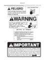
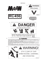
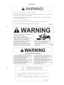
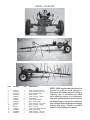
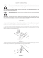
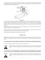
WHEEL RAKE
CARRIER
Published 05-06
Part No. 4702C
OPERATOR'S MANUAL
This Operator's Manual is an integral part of the safe operation
of this machine and must be maintained with the unit at all
times. READ, UNDERSTAND, and FOLLOW the Safety and
Operation Instructions contained in this manual before
operating the equipment.
M&W
1020 South Sangamon Ave.
Gibson City, Illinois 60936
217-784-4261
$0.00
©2006 Alamo Group Inc.
TO THE OWNER/OPERATOR/DEALER
All implements with moving parts are potentially hazardous. There is no substitute for a cautious, safe-minded operator
who recognizes the potential hazards and follows reasonable safety practices. The manufacturer has designed this
implement to be used with all its safety equipment properly attached to minimize the chance of accidents.
BEFORE YOU START!!
Read the safety messages on the implement and shown in your manual. Observe the
rules of safety and common sense!
WARRANTY INFORMATION:
Read and understand the complete Warranty Statement found in this Manual. Fill out the Warranty Registration Form
in full and return it within 30 Days. Make certain the Serial Number of the Machine is recorded on the Warranty Card
and on the Warranty Form that you retain. The use of "will-fit" parts will void your warranty and can cause catastrophic
failure with possible injury or death.
TABLE OF CONTENTS
Specifications ............................................................................................................ 2
Introduction ................................................................................................................ 2
Decals ....................................................................................................................... 3
Decal Location ........................................................................................................... 6
Safety Instructions ..................................................................................................... 7
Assembly ................................................................................................................... 7
Operation ................................................................................................................... 9
Adjusting Ground Pressure Settings ......................................................................... 11
Transporting .............................................................................................................. 12
Maintenance ............................................................................................................. 12
Lubrication ................................................................................................................ 12
1
SPECIFICATIONS
MODEL RC456
Weight (approximate) ............................................................................................. 585 Lbs.
Overall Width of Tool Bar w\Wings Extended ................................................................. 91"
Overall Length ........................................................................................................ 178 1/2"
Hydraulics ............................................................................. Two-way Hydraulics Required
Rake capabilities ...................................................................... Two 4, 5, or 6 Wheel Rakes
Normal Tractor Speed .................................................................................... 15 to 20 MPH
*Do not transport or operate at speeds greater than Normal Tractor Speeds.
INTRODUCTION
The M&W Wheel Rake Carrier has been engineered and built for ease of operation and long service life. The M&W
RC456 Rake Carrier has been designed to transport and operate a pair of 4 Wheel, 5 Wheel, or 6 Wheel Rakes in a
V-type configuration.
It is important that you thoroughly understand the operation of the wheel rake carrier before use. Read through this
manual completely, watching especially for safety symbols (See Illustration Below) which will alert you to possible
hazards. The word "Note" will alert you to special information such as specifications, techniques, reference information
and other supplementary information. The word "Important" is used to point out a note which is of immediate and
urgent nature.
Safety Symbol
It is the users responsibility to read the operator's manual and comply with all instructions pertaining to operation and
maintenance. It is also the users responsibility to inspect the machine at regular intervals and repair or replace worn
or damaged parts when continued use would cause damage or excessive wear to other parts.
The manufacturer reserves the right to make changes, specifications, or improvements without incurring obligations
to add them to rake carriers sold before the changes.
When ordering parts for your rake carrier, please specify the part number and the name of the part as shown in the
parts section. Please give the serial number of the rake carrier, which is located on the rear of the main frame tube,
in all correspondence when referring to the rake carrier. Record the serial number and purchase date here for future
reference.
Serial No. _______________________ Model __________________________ Purchase Date _____________
Important: When this machine is traded or sold, make sure this manual accompanies the machine so future operators
will have complete operating instructions and safety warnings available to them.
2
DECALS
These decals are installed for safety. They must be visible at all times and kept in good condition. The buyer of this
machine assumes responsibility for maintaining these decals.
4
14
3
2
3
DECALS
13
6
7
RC456
12
2738332
8
10
9
4
DECALS
5
11
1
15
5
DECAL LOCATION
ITEM
PART NO.
QTY.
DESCRIPTION
1
2
3
4
5
6
7
8
9
10
11
12
13
14
15
999200
00771039
00763977
00725746
3048304
2438345
3048302
02962765
3048303
5W119
999001
2738332
02962764
00756059
3668308
1
1
1
1
1
2
2
2
2
1
1
2
2
1
2
Decal, General Warning
Decal, Replacement Parts
Decal, Notice to Owner
Decal, Peligro
Decal, Warning - Operate
Decal, M&W
Decal, Model RC456
Decal, Multi Hazard
Decal, Warning - Stay Clear
Decal, Warning - Speed
Decal, Warning
Decal, Red Oblong Reflector
Decal, Pinch Point
Decal, Warning - Oil Leak
Decal, Warning Transport
6
NOTE: M&W supplies safety decals on this
product to promote safe operation.
Damage to the decals may occur while in
shipping, use, or reconditioning. M&W
cares about the safety of its customers,
operators, and bystanders, and will replace
the safety decals on this product in the field,
free of charge (Some shipping and handling
charges may apply). Contact your M&W
dealer to order replacement decals.
SAFETY INSTRUCTIONS
CAUTION!
This machine should never be operated by anyone who is not familiar with the product and has not read
the instruction manual. Do not operate the rake where people or animals are in the immediate area.
Never allow passengers on the tractor while operating.
When changing the configuration of the rake, make sure everyone is clear of the folding and hinged parts and avoid
pinch points which can cause serious injury.
CAUTION!
Make sure rakes are locked whenever they are in the folded position before working around the machine or before transporting.
IMPORTANT! The decals listed below are installed on the rake carrier for your safety. They must be visible at all
times and kept in good condition. The buyer of this machine assumes responsibility for maintaining these warning
decals. If they become damaged or unreadable for any reason, replace immediately.
ASSEMBLY
1. Layout and identify all parts. Many parts will be partially assembled by the manufacturer. The main frame and swing
arms are already assembled, along with the tension spring and adjustment chains, and the hydraulic cylinder is
installed by the manufacturer. The spindles and hubs are also installed on the axle.
2. Support the main frame assembly on sturdy stands and install the axle assembly under the main frame. Measure
from the rear of the main frame 17" to 18" to the back side of the axle tube. Secure the axle with three 4" x 5 1\2" x 5\8"
U-Bolts, lockwashers, and nuts (See Illustration 1).
The axle may need to be moved forward or backward until the caster wheels on the wings roll in the proper location on
the axle ramps (See Illustration 2). Tighten the U-Bolts when axle is properly located.
7
3. Install the tongue on the main frame using three 5/8" x 2" bolts, nuts, and lockwashers. On some models, a
reinforcing plate is used. If so, install the plate beneath the tongue and main frame using six 1/2" x 1 1/2" bolts, nuts,
and lockwashers. Install a hose support on the top bolt as the tongue is installed. If the optional extended tongue is
used, install the extension between the main frame and tongue using the bolts provided and install a second reinforcing
plate if used.
4. Install the threaded rod hose holder in the threaded hole on top of the tongue. Install a 1/2" jam nut on the rod before
installing. Tighten the jam nut after the rod is position.
5. Install the support jack on the tongue using the pin supplied.
6. Install the tire on the wheel rims supplied and install the rims on the hubs. Torque the four lug bolts on each wheel
to 75 Ft-Lbs.
Note: The height of the tires used will effect the operation of the wheel rakes. It is recommended that 195 x 14" tires
be used.
7. Two hydraulic hoses, 1/4" x 188" and one 1/4" x 192" are included. Connect the longer hose to the rear port of the
cylinder using a 900 elbow. Connect the shorter hose to the front port using a 900 elbow. Route the hoses through the
hose holder on the tongue. Install the restrictor swivel on the male end of one hose. When the cylinder is replaced or
reinstalled, the ports must go to the left side of the carrier when facing forward.
Important: Do not operate without restrictor installed.
Before installing hydraulic lines, check for foreign material in lines. Keep hoses and fittings clean at all times. Be sure
all connections are properly sealed to avoid leakage.
CAUTION!
Do not exceed manufacturers maximum hydraulic system pressure at 2500 psi.
If the optional tongue extension is used, install the two 1/4" x 48" hoses included in the kit on the 188" and 192" hoses
using the 1/2" NPT couplers provided. Install the restrictor fitting on the end of one extension hose.
WARNING!
Always wear protective eye goggles and use a magnifying glass or hold a piece of wood on suspected
leaks. Pinhole hydraulic leaks can penetrate skin. Do not touch.
Note: If fluid penetrates the skin, it must be surgically removed within a few hours by a doctor familiar with the form of
injury or gangrene may result. Make sure the weight of the machine has been taken off the hydraulic cylinder before
disconnecting hydraulic hoses.
8. Install the hose holder on the tongue center just forward of the cylinder using a capscrew and lockwasher. Secure
the hoses on the holder with the clip, capscrew, lockwasher, and nut.
9. Install the rake mount assemblies on the wings, as shown, using two U-bolts, nuts, and lockwashers to secure
each assembly.
Note: Left and right mounting heads are used. See the Parts List on page 10 for proper identification of left and right
mounting heads (Part No. 6 & 6A).
Measure from the front edge of the wing to the center of the rake mount to determine the approximate location of the
rake (See Illustration 3).
4 Wheel Rakes
35"
5 Wheel Rakes
25"
6 Wheel Rakes
13"
8
The settings on the previous page are only approximate settings. The final position on the wing is determined by the
desired width of the windrow. Moving the rake mounts forward on the wing makes the windrow wider. Moving the rake
mounts rearward makes the windrow narrower.
10. Install the wheel rakes on the mount tube by inserting the rakes main frame tube into the tubes on the rake mounts.
This operation can be made easier if the carrier is connected to the tractor tongue, hydraulics are connected and the
wings are extended. Install the clamps on the rake tubes. Tighten the 1/2" x 1 1/2" bolts, nuts, and lockwashers
snugly. The ears at the top of the clamp should be on either side of the tab on the mount tube so the rake can "float"
as it works.
Important: When the rake is positioned correctly, drill a hole through the clamp and the rake tube and install a 5/16"
shear bolt, lockwasher, and nut (See Illustration 3).
Before operating this machine, lubrication of specific parts must be completed. Lubricate the points listed before
operating for the first time and periodically as shown in the chart (See page 7).
Before operation, check tightness of lug bolts and spindle setscrews.
OPERATION
Important: Before operation, the operator should be familiar with these operation instructions and operation of tractor.
Do not allow an unqualified person or one under the influence of medication or intoxicating substances to operate the
tractor.
1. Connect the machine to the tractor tongue using a 3/4" hitch pin with a retaining clip. The adjustable jack will allow
the tongue to be raised or lowered during hookup. After hookup to the tractor, store the jack in the horizontal position.
2. Connect the hydraulic inlet and outlet hoses to the tractor hydraulic system.
CAUTION!
Make sure a restrictor is installed on one of the hydraulic lines. Failure to use a restrictor will allow the
machine to fold and unfold rapidly and could result in damage to the machine, and injury to bystanders.
3. To lower the rakes to the working position, pull the transport pins for each wing and apply hydraulic pressure to
retract the cylinder. The wings will spread apart and the rake will lower to the working position as the castor wheels
move down the axle ramps. The transport pins can be stored in the raised position by installing clips in upper holes.
CAUTION!
Operate the hydraulic cylinder through the cycle a few times to expel all air through the system.
Failure to fully charge the hydraulic system could result in injury when the rakes fall abruptly to the
ground.
9
CAUTION!
Make sure the area around the machine is clear before lowering. Do not lower rakes when people
or pets are near the rakes or folding mechanism.
4. Set the rake angle by repositioning the 5/8" bolt in the rake mounting bracket. Six holes are available for adjustments (See Illustration 4).
See the rake operator's manual for more information on setting the rakes.
5. Working speed is normally 5 to 10 mph. Speed varies with different hay conditions or terrain. Consult the rake
operator's manual for complete operation instructions.
6. To raise the rakes, apply hydraulic pressure to extend the hydraulic cylinder. When the wings are in the retracted
position, install the transport pins in the frame to lock the wings in place.
Note: The wings must be adjusted so that both wings retract into the transport position at approximately the same
time. With the rakes removed from the wings, disconnect the adjustable link between the sliding cylinder mount and
the left wing. Clear the area around the machine and extend the cylinder until the right wing just retracts into the lock
position. Manually retract the left arm to the same position and adjust the link until the pin drops into the pivot point.
Turning the threaded rod end "in" will cause the wing to move towards the tongue. Secure the pin when the adjustment
is complete (See Illustration 5).
CAUTION!
The linkage can be adjusted with the rakes installed ONLY if the left wing is locked in the transport
position. If the wing is allowed to extend to the point where the caster wheel is on the axle ramp, the
rake can fall rapidly and possibly cause an injury.
10
ADJUSTING GROUND PRESSURE SETTINGS
7. Use this chart to adjust the rake ground pressure. When set properly, individual rake wheels should be light
enough to float over the ground while maintaining a constant ground speed. Each adjustable chain is equipped with
a threaded rod that is used to balance weight of the left and right side, and to make any fine adjustments. The chain
has three flexible links. If the illustrated settings do not flatten or bow down the leaf spring as shown, then relocate the
clevis on the second chain link and readjust.
CAUTION!
The threaded rod in the adjustable link should be adjusted so that no
more than 3/4" of threads are showing (See Illustration 6).
CAUTION!
Never try to adjust spring tension with the rake in the working position.
Raise the rakes to the transport position before making adjustments.
Failure to do so could result in serious injury.
8 WHEEL RAKE SETTINGS
The chain clevis should be in
holes 3 or 4 with the leaf spring
slightly bowed up or flat.
10 WHEEL RAKE SETTINGS
The chain clevis should be in
holes 2 or 3 with the leaf spring
flat or bowed down slightly.
12 WHEEL RAKE SETTINGS
The chain clevis should be in
holes 1 or 2 with the leaf spring
bowed down slightly to bowed
down.
Illustration 7
8. The width of the windrow can be adjusted by moving one or both rakes forward or backward on the wings. To do this,
loosen the U-Bolts securing the rake mounts and reposition the mounts. Moving the mounts forward will widen the
windrow. Moving the mounts back will make the windrow narrow. Extend the wings and check for clearance around the
tires before operating.
When one rake is to be used alone, leave the locking pin in place on the wing not used and pull the pin securing the
linkage between the sliding cylinder mount and the unused wing. The operation of the remaining rake is not affected.
11
R 8-1-00
TRANSPORTING
To transport, retract the wings until they are in place against the tongue and install the locking pins so the pins capture
the lugs on the wings. Secure the pins in place with hairpin cotter pins.
CAUTION!
Never transport rakes without locking pins in place.
Avoid sharp turns during transport to prevent contact between the rakes and the machine. Slow down when approaching
trees, fences, or ditches to avoid damage to rakes.
CAUTION!
When towing on public roads, a slow moving vehicle (SMV) sign should be installed on the tractor so
it is visible to vehicles following. Warning lights should also be installed on the tractor so they are
visible to other motorists. Comply with state and local safety requirements at all times.
MAINTENANCE
1. Check hydraulic hoses periodically for cracks, abrasions, or leaks. Replace defective hoses immediately. Replace
worn or broken hoses and fittings with factory replacement parts only.
2. To extend the life of the hydraulic cylinder and hoses, store the machine under cover. If cover is not available, remove
the cylinder and hoses and store under cover.
3. Check tightness of lug bolts and spindle setscrews after one hour of operation and every six months thereafter.
Check tire pressure whenever maintenance is performed.
LUBRICATION
Lubricate all points before operating for the first time and periodically as shown in the chart below. Keep all lubrication
fittings free of dirt and contaminates.
12
M&W
LIMITED
WARRANTY
1. LIMITED WARRANTIES
1.01.M&W warrants for one year from the purchase date to the original non-commercial, governmental, or municipal
purchaser (“Purchaser”) and warrants for six months to the original commercial or industrial purchaser (“Purchaser”)
that the goods purchased are free from defects in material or workmanship.
1.02.Manufacturer will replace for the Purchaser any part or parts found, upon examination at one of its factories, to be
defective under normal use and service due to defects in material or workmanship.
1.03.This limited warranty does not apply to any part of the goods which has been subjected to improper or abnormal use,
negligence, alteration, modification, or accident, damaged due to lack of maintenance or use of wrong fuel, oil, or
lubricants, or which has served its normal life. This limited warranty does not apply to any part of any internal
combustion engine, or expendable items such as blades, shields, guards, or pneumatic tires except as specifically found
in your Operator’s Manual.
1.04.Except as provided herein, no employee, agent, Dealer, or other person is authorized to give any warranties of any
nature on behalf of Manufacturer.
2. REMEDIES AND PROCEDURES.
2.01.This limited warranty is not effective unless the Purchaser returns the Registration and Warranty Form to Manufacturer
within 30 days of purchase.
2.02.Purchaser claims must be made in writing to the Authorized Dealer (“Dealer”) from whom Purchaser purchased the
goods or an approved Authorized Dealer (“Dealer”) within 30 days after Purchaser learns of the facts on which the
claim is based.
2.03.Purchaser is responsible for returning the goods in question to the Dealer.
2.04.If after examining the goods and/or parts in question, Manufacturer finds them to be defective under normal use and
service due to defects in material or workmanship, Manufacturer will:
(a) Repair or replace the defective goods or part(s) or
(b) Reimburse Purchaser for the cost of the part(s) and reasonable labor charges (as determined by Manufacturer)
if Purchaser paid for the repair and/or replacement prior to the final determination of applicability of the warranty
by Manufacturer.
The choice of remedy shall belong to Manufacturer.
2.05.Purchaser is responsible for any labor charges exceeding a reasonable amount as determined by Manufacturer and
for returning the goods to the Dealer, whether or not the claim is approved. Purchaser is responsible for the transportation cost for the goods or part(s) from the Dealer to the designated factory.
3. LIMITATION OF LIABILITY.
3.01.MANUFACTURER DISCLAIMS ANY EXPRESS (EXCEPT AS SET FORTH HEREIN) AND IMPLIED WARRANTIES
WITH RESPECT TO THE GOODS INCLUDING, BUT NOT LIMITED TO, MERCHANTABILITY AND FITNESS
FOR A PARTICULAR PURPOSE.
3.02.MANUFACTURER MAKES NO WARRANTY AS TO THE DESIGN, CAPABILITY, CAPACITY, OR SUITABILITY FOR
USE OF THE GOODS.
3.03.EXCEPT AS PROVIDED HEREIN, MANUFACTURER SHALL HAVE NO LIABILITY OR RESPONSIBILITY TO
PURCHASER OR ANY OTHER PERSON OR ENTITY WITH RESPECT TO ANY LIABILITY, LOSS, OR DAMAGE
CAUSED OR ALLEGED TO BE CAUSED DIRECTLY OR INDIRECTLY BY THE GOODS INCLUDING, BUT NOT
LIMITED TO, ANY INDIRECT, SPECIAL, CONSEQUENTIAL, OR INCIDENTAL DAMAGES RESULTING FROM
THE USE OR OPERATION OF THE GOODS OR ANY BREACH OF THIS WARRANTY. NOT WITHSTANDING THE
ABOVE LIMITATIONS AND WARRANTIES, MANUFACTURER’S LIABILITY HEREUNDER FOR DAMAGES
INCURRED BY PURCHASER OR OTHERS SHALL NOT EXCEED THE PRICE OF THE GOODS.
3.04.NO ACTION ARISING OUT OF ANY CLAIMED BREACH OF THIS WARRANTY OR TRANSACTIONS UNDER
THIS WARRANTY MAY BE BROUGHT MORE THAN TWO (2) YEARS AFTER THE CAUSE OF ACTION HAS
OCCURRED.
4. MISCELLANEOUS.
4.01.Proper Venue for any lawsuits arising from or related to this limited warranty shall be only in Guadalupe County,
Texas.
4.02.Manufacturer may waive compliance with any of the terms of this limited warranty, but no waiver of any terms shall
be deemed to be a waiver of any other term.
4.03.If any provision of this limited warranty shall violate any applicable law and is held to be unenforceable, then the
invalidity of such provision shall not invalidate any other provisions herein.
4.04.Applicable law may provide rights and benefits to purchaser in addition to those provided herein.
KEEP FOR YOUR RECORDS
ATTENTION: Purchaser should fill in the blanks below for his reference when buying repair parts and/or for proper machine
identification when applying for warranty.
M&W Implement Model _____________________________________ Serial Number ________________________________
Date Purchased __________________________________________ Dealer ______________________________________
ATTENTION:
READ YOUR OPERATOR'S MANUAL
M&W
An Alamo Group Company
1020 South Sangamon Ave.
Gibson City, Illinois 60936
217-784-4261
TO THE OWNER/OPERATOR/DEALER
To keep your implement running efficiently and safely, read your manual thoroughly and follow these directions and
the Safety Messages in this Manual. The Table of Contents clearly identifies each section where you can easily find
the information you need.
The OCCUPATIONAL SAFETY AND HEALTH ACT (1928.51 Subpart C) makes these minimum safety requirements
of tractor operators:
REQUIRED OF THE OWNER:
1.
2.
3.
4.
Provide a Roll-Over-Protective Structure that meets the requirements of this Standard; and
Provide Seatbelts that meet the requirements of this paragraph of this Standard and SAE J4C; and
Ensure that each employee uses such Seatbelt while the tractor is moving; and
Ensure that each employee tightens the Seatbelt sufficiently to confine the employee to the protected
area provided by the ROPS.
REQUIRED OF THE OPERATOR
1.
2.
3.
4.
5.
6.
7.
8.
9.
Securely fasten seatbelt if the tractor has a ROPS.
Where possible, avoid operating the tractor near ditches, embankments, and holes.
Reduce speed when turning, crossing slopes, and on rough, slick, or muddy surfaces.
Stay off slopes too steep for safe operation.
Watch where you are going - especially at row ends, on roads, and around trees.
Do not permit others to ride.
Operate the tractor smoothly - no jerky turns, starts, or stops.
Hitch only to the drawbar and hitch points recommended by the tractor manufacturer.
When the tractor is stopped, set brakes securely and use park lock, if available.
Keep children away from danger all day, every
day...
Equip tractors with rollover protection (ROPS)
and keep all machinery guards in place...
Please work, drive, play and live each day with
care and concern for your safety and that of your
family and fellow citizens.
Wheel Rake Carrier
Wheel Rake Carrier - SOM - 05/06
Printed U.S.A.
P/N 4702C
An Alamo Group Company
M&W®
1020 S. Sangamon Ave.
Gibson City, IL 60936-9907
Please fold (do not tear), tape, and drop in any mailbox.
PLEASE FILL OUT OWNER WARRANTY REGISTRATION INFORMATION
SIGN, AND DROP LAST COPY IN ANY MAILBOX.
IMPORTANT!
TO PLACE THIS WARRANTY IN EFFECT,
THIS WARRANTY REGISTRATION MUST BE
FILLED OUT, SIGNED, AND MAILED WITHIN 30
DAYS OF DELIVERY DATE OF THIS MACHINE.
DEALER AND PURCHASER MUST SIGN.
ATTENTION: ANY CLAIM SUBMITTED TO SERVIS-RHINO®
WILL BE REFUSED UNTIL COMPLETED, SIGNED
WARRANTY REGISTRATION CARD IS ON FILE.
M&W WARRANTY REGISTRATION INFORMATION
MONTH
Serial No.
M&W Model
DAY
YEAR
Purchase Date
Purchaser
Last Name
Street & No., RFD,
Box, &/or Apt. No.
First Name
City
M.I.
State or
Province
ZIP
State or
Province
ZIP
Dealer
City
•
I have informed the Purchaser of this product of Warranty terms, provisions, and procedures that are applicable, reviewed the contents of the Operator’s Manual
including safety equipment, safe operation, and maintenance, reviewed the Safety Signs on implement (and tractor if possible), shown the AEM Mower Safety
Practices Video, and reviewed Purchaser’s responsibility to train his operators in safe operation.
• IMPLEMENTS: I have explained that Deflectors, Chain Guards, or Solid Skirts must be maintained in good repair and installed except in areas where persons,
vehicles, livestock, or other property will not be endangered by thrown objects and where such safety equipment would prevent the mower’s reasonable performance
of its assigned task.
• DRIVELINES: I have made certain that all driveline, gearbox, and other shields are in good repair and fastened securely in place to prevent injuries from
entanglement or thrown objects.
•
HYDRAULIC MACHINES: I have explained the necessity of using clean hydraulic oil, changing filters as instructed, stopping leaks, damage caused by
operating with over-heated oil, caring for hoses, using hoses of proper rating, the necessity of maintaining the specified operating pressure, and the potential hazard
of oil's penetrating the skin.
• BOOM-TYPE or FOLDING-TYPE IMPLEMENTS:
I have explained that it is not possible to guard against thrown objects when the head is lifted off ground
and that operator is responsible to watch out for persons in the area. I have explained that the lifted mower head or boom can contact overhead obstructions with
damage to cables and telephone lines and possible injury. I have explained that the extended head or boom or retracted boom can contact power lines with resulting
electrocution injury or death and that operator is responsible for keeping clear of such hazards.
Dealer’s Signature ___________________________________ Date ______________
I have been instructed on the paragraphs above, received and have been shown the AEM Mower Safety Practices Video and have been instructed in the contents
of the Operator’s Manual including safety signs, safety equipment, safe operation, maintenance, and the potential hazards of unauthorized alteration or modification
of the product. I have been informed of the warranty provisions and know that the warranty is not in effect until this form is received by Alamo Group.
I understand the Implement Guarding statements above and the potential hazards of operating without such guards. I understand that the operator is responsible for
the safety of others in the area. I have examined the product and accept it as being complete and in satisfactory condition with all required guards.
Purchaser’s Signature ___________________________________ Date ______________
Do not tear.
Do not tear.
PRE-DELIVERY SERVICE
CHECK AND ADJUST OR LUBRICATE AS REQUIRED
See Operator’s Manual for Details
Inspection Performed - Warranty and Safety Procedures Explained - Installation Complete
LUBRICATION & HYDRAULICS
Gearboxes & Speed Increaser (Oil Levels)
Hydraulic Oil Level (External. Tank)
Tractor Hydraulic Oil Level
Hydraulic Hoses (No Kinks, Binds, or Leaks)
Hydraulic Hose Connections are Tight (No Leaks)
MOWER
Spindle And Motor Bolts Properly Torqued
Spindle Housing Bearings are lubricated
Blade Carrier Bolts Properly Torqued / Retaining Pin In Place
Mower Cutting Height And Level Adjusted
Belt Alignment And Tension Adjusted
Driveline Clutch (Torque Limiter) (Adjust And Run In)
All Hardware Properly Torqued
Tire Air Pressure / Lug Nuts (Correct Torque)
Wheel Bearings (Check, Grease, And Preload)
ATTACHMENTS & INSTALLATION
Thrown Object Deflectors Front And Rear
Correct Blade Rotation Direction
Wing transport locks and latches
Mower head transport support bracket
All Bolts - Pins And Nuts (Proper Torque)
MOWER TO TRACTOR CONNECTION
Draw Bar Length (Check And Set)
Axle Height (Adjusted)
Cutting Height (Adjust)
Mount Kit Pre-Operation Check Complete
Mower Wing (Adjust Level With The Center)
Mower Wing (Check For Proper Raising Operation)
Pull Type Hitch (Height Adjustment)
Mounting Hardware Properly Torqued
SAFETY ITEMS
Protective Shields (Operation And Installation)
S.M.V. Emblem (Installed)
Neutral Safety & Cut - Off Switches work properly
Safety Decals (Installed in good condition)
Operator’s Manual (Supplied in Canister)
AEM Mower Safety Manual (Supplied in Canister)
AEM Mower Safety Video has been shown to Purchaser
_________
Pur. Intitials
AEM Mower Safety Video has been presented to Purchaser ________
Pur. Intitials
Purchaser's Signature _________________________ Date __________ Dealer's Signature ________________________ Date __________
TEAR • TEAR • TEAR • TEAR • TEAR • TEAR • TEAR • TEAR • TEAR • TEAR • TEAR • TEAR • TEAR • TEAR • TEAR • TEAR • TEAR • TEAR • TEAR • TEAR • TEAR • TEAR • TEAR • TEAR • TEAR
BEFORE MAILING WARRANTY CARD, MAKE SURE ALL INFORMATION IS LEGIBLE
®
2. REMOVE WHITE COPY FOR CUSTOMER RECORDS.
3. REMOVE YELLOW COPY FOR DEALERS RECORDS.
4. MAIL LAST CARD POSTAGE FREE.
M&W® WARRANTY REGISTRATION INFORMATION
MONTH
Serial No.
M&W Model
Purchaser
Last Name
Street & No., RFD,
Box, &/or Apt. No.
City
DAY
YEAR
Purchase Date
First Name
M.I.
State or
Province
ZIP
State or
Province
ZIP
Dealer
City
•
I have informed the Purchaser of this product of Warranty terms, provisions, and procedures that are applicable, reviewed the contents of the Operator’s Manual
including safety equipment, safe operation, and maintenance, reviewed the Safety Signs on implement (and tractor if possible), shown the AEM Mower Safety
Practices Video, and reviewed Purchaser’s responsibility to train his operators in safe operation.
• IMPLEMENTS: I have explained that Deflectors, Chain Guards, or Solid Skirts must be maintained in good repair and installed except in areas where persons,
vehicles, livestock, or other property will not be endangered by thrown objects and where such safety equipment would prevent the mower’s reasonable performance
of its assigned task.
• DRIVELINES: I have made certain that all driveline, gearbox, and other shields are in good repair and fastened securely in place to prevent injuries from
entanglement or thrown objects.
•
HYDRAULIC MACHINES: I have explained the necessity of using clean hydraulic oil, changing filters as instructed, stopping leaks, damage caused by
operating with over-heated oil, caring for hoses, using hoses of proper rating, the necessity of maintaining the specified operating pressure, and the potential hazard
of oil's penetrating the skin.
• BOOM-TYPE or FOLDING-TYPE IMPLEMENTS:
I have explained that it is not possible to guard against thrown objects when the head is lifted off ground
and that operator is responsible to watch out for persons in the area. I have explained that the lifted mower head or boom can contact overhead obstructions with
damage to cables and telephone lines and possible injury. I have explained that the extended head or boom or retracted boom can contact power lines with resulting
electrocution injury or death and that operator is responsible for keeping clear of such hazards.
Dealer’s Signature ___________________________________ Date ______________
I have been instructed on the paragraphs above, received and have been shown the AEM Mower Safety Practices Video and have been instructed in the contents
of the Operator’s Manual including safety signs, safety equipment, safe operation, maintenance, and the potential hazards of unauthorized alteration or modification
of the product. I have been informed of the warranty provisions and know that the warranty is not in effect until this form is received by Alamo Group.
I understand the Implement Guarding statements above and the potential hazards of operating without such guards. I understand that the operator is responsible for
the safety of others in the area. I have examined the product and accept it as being complete and in satisfactory condition with all required guards.
DEALER COPY
Purchaser’s Signature ___________________________________ Date ______________
PRE-DELIVERY SERVICE
CHECK AND ADJUST OR LUBRICATE AS REQUIRED
See Operator’s Manual for Details
Inspection Performed - Warranty and Safety Procedures Explained - Installation Complete
LUBRICATION & HYDRAULICS
Gearboxes & Speed Increaser (Oil Levels)
Hydraulic Oil Level (External. Tank)
Tractor Hydraulic Oil Level
Hydraulic Hoses (No Kinks, Binds, or Leaks)
Hydraulic Hose Connections are Tight (No Leaks)
MOWER
Spindle And Motor Bolts Properly Torqued
Spindle Housing Bearings are lubricated
Blade Carrier Bolts Properly Torqued / Retaining Pin In Place
Mower Cutting Height And Level Adjusted
Belt Alignment And Tension Adjusted
Driveline Clutch (Torque Limiter) (Adjust And Run In)
All Hardware Properly Torqued
Tire Air Pressure / Lug Nuts (Correct Torque)
Wheel Bearings (Check, Grease, And Preload)
ATTACHMENTS & INSTALLATION
Thrown Object Deflectors Front And Rear
Correct Blade Rotation Direction
Wing transport locks and latches
Mower head transport support bracket
All Bolts - Pins And Nuts (Proper Torque)
MOWER TO TRACTOR CONNECTION
Draw Bar Length (Check And Set)
Axle Height (Adjusted)
Cutting Height (Adjust)
Mount Kit Pre-Operation Check Complete
Mower Wing (Adjust Level With The Center)
Mower Wing (Check For Proper Raising Operation)
Pull Type Hitch (Height Adjustment)
Mounting Hardware Properly Torqued
SAFETY ITEMS
Protective Shields (Operation And Installation)
S.M.V. Emblem (Installed)
Neutral Safety & Cut - Off Switches work properly
Safety Decals (Installed in good condition)
Operator’s Manual (Supplied in Canister)
AEM Mower Safety Manual (Supplied in Canister)
AEM Mower Safety Video has been shown to Purchaser
_________
Pur. Intitials
AEM Mower Safety Video has been presented to Purchaser ________
Pur. Intitials
Purchaser's Signature _________________________ Date __________ Dealer's Signature ________________________ Date __________
TEAR • TEAR • TEAR • TEAR • TEAR • TEAR • TEAR • TEAR • TEAR • TEAR • TEAR • TEAR • TEAR • TEAR • TEAR • TEAR • TEAR • TEAR • TEAR • TEAR • TEAR • TEAR • TEAR • TEAR • TEAR
1. PRINT FIRMLY.
2. REMOVE WHITE COPY FOR CUSTOMER RECORDS.
3. REMOVE YELLOW COPY FOR DEALERS RECORDS.
4. MAIL LAST CARD POSTAGE FREE.
M&W® WARRANTY REGISTRATION INFORMATION
MONTH
Serial No.
M&W Model
Purchaser
Last Name
Street & No., RFD,
Box, &/or Apt. No.
City
DAY
YEAR
Purchase Date
First Name
M.I.
State or
Province
ZIP
State or
Province
ZIP
Dealer
City
•
I have informed the Purchaser of this product of Warranty terms, provisions, and procedures that are applicable, reviewed the contents of the Operator’s Manual
including safety equipment, safe operation, and maintenance, reviewed the Safety Signs on implement (and tractor if possible), shown the AEM Mower Safety
Practices Video, and reviewed Purchaser’s responsibility to train his operators in safe operation.
• IMPLEMENTS: I have explained that Deflectors, Chain Guards, or Solid Skirts must be maintained in good repair and installed except in areas where persons,
vehicles, livestock, or other property will not be endangered by thrown objects and where such safety equipment would prevent the mower’s reasonable performance
of its assigned task.
• DRIVELINES: I have made certain that all driveline, gearbox, and other shields are in good repair and fastened securely in place to prevent injuries from
entanglement or thrown objects.
•
HYDRAULIC MACHINES: I have explained the necessity of using clean hydraulic oil, changing filters as instructed, stopping leaks, damage caused by
operating with over-heated oil, caring for hoses, using hoses of proper rating, the necessity of maintaining the specified operating pressure, and the potential hazard
of oil's penetrating the skin.
• BOOM-TYPE or FOLDING-TYPE IMPLEMENTS:
I have explained that it is not possible to guard against thrown objects when the head is lifted off ground
and that operator is responsible to watch out for persons in the area. I have explained that the lifted mower head or boom can contact overhead obstructions with
damage to cables and telephone lines and possible injury. I have explained that the extended head or boom or retracted boom can contact power lines with resulting
electrocution injury or death and that operator is responsible for keeping clear of such hazards.
Dealer’s Signature ___________________________________ Date ______________
I have been instructed on the paragraphs above, received and have been shown the AEM Mower Safety Practices Video and have been instructed in the contents
of the Operator’s Manual including safety signs, safety equipment, safe operation, maintenance, and the potential hazards of unauthorized alteration or modification
of the product. I have been informed of the warranty provisions and know that the warranty is not in effect until this form is received by Alamo Group.
I understand the Implement Guarding statements above and the potential hazards of operating without such guards. I understand that the operator is responsible for
the safety of others in the area. I have examined the product and accept it as being complete and in satisfactory condition with all required guards.
CUSTOMER COPY
Purchaser’s Signature ___________________________________ Date ______________
PRE-DELIVERY SERVICE
CHECK AND ADJUST OR LUBRICATE AS REQUIRED
See Operator’s Manual for Details
Inspection Performed - Warranty and Safety Procedures Explained - Installation Complete
LUBRICATION & HYDRAULICS
Gearboxes & Speed Increaser (Oil Levels)
Hydraulic Oil Level (External. Tank)
Tractor Hydraulic Oil Level
Hydraulic Hoses (No Kinks, Binds, or Leaks)
Hydraulic Hose Connections are Tight (No Leaks)
MOWER
Spindle And Motor Bolts Properly Torqued
Spindle Housing Bearings are lubricated
Blade Carrier Bolts Properly Torqued / Retaining Pin In Place
Mower Cutting Height And Level Adjusted
Belt Alignment And Tension Adjusted
Driveline Clutch (Torque Limiter) (Adjust And Run In)
All Hardware Properly Torqued
Tire Air Pressure / Lug Nuts (Correct Torque)
Wheel Bearings (Check, Grease, And Preload)
ATTACHMENTS & INSTALLATION
Thrown Object Deflectors Front And Rear
Correct Blade Rotation Direction
Wing transport locks and latches
Mower head transport support bracket
All Bolts - Pins And Nuts (Proper Torque)
MOWER TO TRACTOR CONNECTION
Draw Bar Length (Check And Set)
Axle Height (Adjusted)
Cutting Height (Adjust)
Mount Kit Pre-Operation Check Complete
Mower Wing (Adjust Level With The Center)
Mower Wing (Check For Proper Raising Operation)
Pull Type Hitch (Height Adjustment)
Mounting Hardware Properly Torqued
SAFETY ITEMS
Protective Shields (Operation And Installation)
S.M.V. Emblem (Installed)
Neutral Safety & Cut - Off Switches work properly
Safety Decals (Installed in good condition)
Operator’s Manual (Supplied in Canister)
AEM Mower Safety Manual (Supplied in Canister)
AEM Mower Safety Video has been shown to Purchaser
_________
Pur. Intitials
AEM Mower Safety Video has been presented to Purchaser ________
Pur. Intitials
Purchaser's Signature _________________________ Date __________ Dealer's Signature ________________________ Date __________
TEAR • TEAR • TEAR • TEAR • TEAR • TEAR • TEAR • TEAR • TEAR • TEAR • TEAR • TEAR • TEAR • TEAR • TEAR • TEAR • TEAR • TEAR • TEAR • TEAR • TEAR • TEAR • TEAR • TEAR • TEAR
1. PRINT FIRMLY.