1
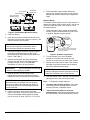
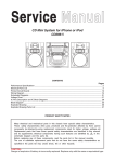
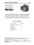
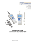
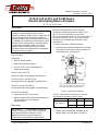
Installation Instructions D- Series
Issue Date October 6, 2003
D-70, D-140, D-210, and D-280 Series
Electric Non-Spring Return Actuators
Parts Included
All Models
•
•
Delta D- Series actuator
To mount the actuator, proceed as follows:
1. Press and hold the gear release lever, and rotate
the coupler to the 0 or 90° position. Release the
gear release lever. (See Figure 1.)
U-bolt
with
Clamp
Nuts (2)
Shaft Center
DDA-160 anti-rotation bracket
90
two No. 12-24 x 1/2 in. self-tapping hex
washer-head screws
0
•
Mount D- Series actuators in any convenient
orientation. Install the actuators on a 3/8 to 3/4 in.
(9.5 to 19 mm) round shaft or a 3/8 to 5/8 in.
(9.5 to 16 mm) square shaft, 2 in. (51 mm) or longer. If
the shaft is less than 2 in. (51 mm) long, install an
extension recommended by the damper or valve
manufacturer.
60 30
30
Coupler
90
The D- Series actuators are
IMPORTANT:
intended to control equipment under normal
operating conditions. Where failure or malfunction of
a D- Series actuator could lead to an abnormal
operating condition that could cause personal injury
or damage to the equipment or other property, other
devices (limit or safety controls) or systems (alarm
or supervisory) intended to warn of, or protect
against, failure or malfunction of the D- Series
actuator must be incorporated into and maintained
as part of the control system.
0
Installation
(8, 16, 24, and 32 N·m)
60
D24-210 and D24-280
Include one DDA-105 pluggable 3-terminal block
Gear
Release
D24-210-FB135 and D24-FB1K
Include two DDA-105 pluggable 3-terminal blocks
D24-210-A and D24-280-A
Include three DDA-105 pluggable 3-terminal blocks
Special Tools Needed
•
•
torque wrench with 10 mm socket
digital voltmeter or DDA-200 commissioning tool
(for the models with zero and span
potentiometers)
Mounting
IMPORTANT:
The actuator is intended for
indoor mounting only, with no direct exposure to
water beyond NEMA 2 conditions. Use an
appropriate shield or enclosure where the
environment exceeds NEMA 2 specifications.
© 2003 Delta Control Products, Inc.
Part No. 34-636-836, Rev F
A
Anti-rotation
Bracket
Note: A is the distance from the center of the
holes in the anti-rotation bracket to the center
of the shaft. (See Table 1 for dimensions.)
Figure 1: Mounting Positions
Table 1: Shaft Sizes and Distances from the
Anti-Rotation Bracket to Shaft Center
Shaft Diameter
A Dimensions
(See F igure 1.)
5/8 in.
1/2 in.
3/8 in.
6-1/8 in.
6-3/16 in.
6-1/4 in.
155 mm
157 mm
159 mm
2. Bend or cut the anti-rotation bracket to fit the
damper frame or duct as shown in Figure 2.
1
www.deltacp.com
Slot for Bracket
Anti-rotation
Bracket Tab
No. 12-24 Sheet
Metal Screws (2)
Anti-rotation Bracket
Damper
Frame
Figure 2: Anti-Rotation Bracket Positions
3. Close the damper.
9. Press and hold the gear release. Rotate the
coupler fully closed to fully open to verify that the
damper and actuator rotate freely throughout the
range.
Rotation Range
The actuator comes factory set for 0 to 90° rotation. To
change the rotation range to less than 90°, use the top
scale on the actuator cover, refer to Figure 3, and
proceed as follows:
1. Press and hold the gear release, and rotate the
actuator coupler Counterclockwise (CCW) to the
0° position. Release the gear release.
Coupler
4. Insert the anti-rotation bracket tab into the slot at
the bottom of the actuator (shown in Figure 2), and
slide the actuator onto the shaft.
Back of the
Position
Indicator Hub Actuator
90
0
IMPORTANT:
The tab on the anti-rotation
bracket must fit midpoint in the actuator slot to
prevent actuator binding and premature wear.
5. Use the anti-rotation bracket as a guide, and drill
the holes in the damper frame or duct for the
bracket (based on the measurements obtained in
Figure 1 and Table 1).
6. Attach the anti-rotation bracket to the damper
frame or duct with the two self-tapping screws
provided, using a 1/4 in. (7 mm) flat-blade
screwdriver or 5/16 in. (8 mm) nut driver.
IMPORTANT:
Do not overtighten the mounting
screws to avoid stripping the threads.
7. Slide the actuator onto the damper shaft,
positioning the tab on the anti-rotation bracket
midway into the slot at the bottom of the actuator.
IMPORTANT:
For Variable Air Volume
applications that use a DM24-70 Series actuator,
secure the coupler to the shaft with the damper in
the fully open position to avoid damaging the open
position end-stop.
8. Hold the actuator in place, and evenly hand
tighten each clamp nut onto the U-bolt. Secure the
U-bolt to the damper shaft by tightening clamp
nuts to a torque of 100 to 125 lb·in (11 to 14 N·m).
2
60
30
0
Cover Screw
30
60
CCW
90
Gear
Release
Locking
Clip
Note: The locking clip is factory set
at the missing tooth of the actuator
hub for 90° rotation.
Figure 3: Actuator Components
2. Turn the actuator over, use a flat-blade
screwdriver to release the locking clip, and
remove the coupler from the front of the actuator.
3. Reinsert the coupler into the front of the actuator,
and align the position indicator with the starting
point of the desired rotation range.
IMPORTANT:
Advancing the coupler 90° from
the factory setting prevents the actuator from driving
in either the Clockwise (CW) or CCW direction.
4. Push the coupler into the actuator until the locking
clip snaps over the hub, securing it in place.
Note:
To change the rotation range on:
•
-A models with auxiliary switches, one or both
of the switches may need adjustment. See the
Auxiliary Switches (-A Models) section.
•
-Z and -Z-A models with zero and span
potentiometers, adjust both potentiometers. See
the Potentiometers (Proportional Models) section.
D-70, D-140, D-210, and D-280 Series Electric Non-Spring Return Actuators Installation Instructions
Feedback Signal
For resistance-type feedback, the signal varies with a
change to the rotation range. Resistance feedback
reduction corresponds to the reduced rotation range.
Refer to Figure 5 for the applicable D- Series actuator.
Terminal B lock 1
1
2 3
^- ~
+
+ ~
COM CW CCW
For analog-type feedback, a change to the rotation
range changes the feedback signal and the operating
range proportionally. (See Figure 4.)
90°
Direct
Acting
(DA)
0°
Rotation Range
Coupler Adjustment
75° 60° 45°
30° 15°
15°
30°
45°
60°
75°
0-10 V
10.0 V 8.3 V 6.7 V 5.0 V 3.3 V 1.7 V
Feedback
2-10 V
10.0 V 8.7 V 7.3 V 6.0 V 4.7 V 3.3 V
Feedback
0-10
V
Reverse
0.0 V 1.7 V 3.3 V 5.0 V 6.7 V 8.3 V
Acting Feedback
2-10 V
(RA)
2.0 V 3.3 V 4.7 V 6.0 V 7.3 V 8.7 V
Feedback
Direct or 0-135 ohms 135 Ω 113 Ω 90 Ω 68 Ω 45 Ω 23 Ω
Reverse Feedback
Acting 0-1000 ohms1000 Ω 833 Ω 667 Ω 500 Ω 333 Ω 167 Ω
Feedback
Note: 0-10 V or 2-10 V is available on DM24 models.
0-135 ohms feedback is available on -FB135 models and
0-1000 ohms feedback on FB1K models.
24 VAC
24 VDC
0°
2.0 V
10.0 V
10.0 V
0Ω
0Ω
Figure 4: Nominal Feedback Signal Relative to the
Rotation Range
Wiring
2
~
+
3
~
+
COM CW CCW
24 VAC
24 VDC
On/Off Control
Floating Control
Models: All D24 Series
90°
0.0 V
1
^-
1 2
~
^
- +
24V
3
+
4
+
5 6
+ +
0-20 mA
0-20V
0-10V
1 2 3 4 5
~ ^ + +
^- +
24V CCW CW
COM
6
+
100-10K ohms
0-10V
Proportional Control
Models: DM24
1 = Common
2 = Power
3 = Calibration Out
(for -Z and -Z-A
models only)
4 = Current Input
5 = Voltage Input
6 = Feedback Output
Resistive Input Control
Models: DRM and DRMS
Note: Terminals 3 and 4
function as CCW and CW
references when the
Resistive models are in
the DA mode but as CW
and CCW references
when these models are
in the RA mode.
Terminal B lock 2
!
CAUTION: Risk of Equipment Damage.
Disconnect all power supplies before making wiring
connections or prior to performing maintenance.
Check all wiring connections before applying power
to the system. Short-circuited or improperly
connected wires will result in permanent damage to
the equipment.
IMPORTANT:
Make all wiring connections in
accordance with local, national, or regional
regulations.
Auxiliary Switches
Switch Switch
Switch
S1
S1
S2
10°
80°
10°
NC NO NO NC
Switch
S2
80°
21 22 23 24 25
C1 NC1 NO1 C2 NO2 NC2
(Shown Factory Set)
(Shown Factory Set)
Models: D24-70-A and
Models: D24-210-A and
D24-140-A
D24-280-A
Feedback Potentiometer
CW
CW
0%
100%
11 12 13
Models: D24-70 and D24-140
FB135 = 0 to 135 ohms
FB1K = 0 to 1000 ohms
0%
100%
Wiper (W) CCW CW
Models: D24-210, D24-280
FB135 = 0 to 135 ohms
FB1K = 0 to 1000 ohms
Figure 5: Wiring Diagrams for D- Series Models
D-70, D-140, D-210, and D-280 Series Electric Non-Spring Return Actuators Installation Instructions
3
Through the Conduit Openings
Depending on the D- Series model selected, use one
or both conduit openings. The threaded actuator
conduit openings accept 1/2 in. trade size conduit
fittings. Refer to Figure 6 and proceed as follows:
1. Loosen the cover screw with a Phillips No. 1
screwdriver, and remove the actuator cover.
Cover
Screw
•
one DM24-140 and one DM24-140-Z-A
•
one DM24-210 and one DM24-210-Z
•
one DM24-280 and one DM24-280-A
Note: Do not use D24-70 or -140 or DM24-70 Series
models in tandem.
The Master/Slave Jumper is factory set in the master
position. Determine the method for mounting the two
actuators in tandem: front-to-back (Figure 7 shows the
front view) or back-to-back and proceed as follows:
Plugs
(Conduit Openings)
Figure 6: Location of the Conduit Openings
2. Push the plastic plug out of the conduit opening
with fingertip.
3. Use the Phillips screwdriver to puncture a hole
through the center of the plug, and reinsert the
plug into the conduit opening.
Note: For applications requiring metal conduit,
thread the conduit fitting into the conduit opening and
hand tighten.
IMPORTANT:
Use flexible metallic tubing or its
equivalent with the fitting. Do not overtighten the
conduit fitting into the actuator to avoid damaging
the actuator threads.
4. Insert the cable wires through the plastic plug or
conduit fitting, and connect to the terminal block
using the applicable wiring diagrams in Figure 5.
5. Perform the procedures appropriate to the specific
application, as described in the Tandem Operation
and Setup and Adjustments sections.
6. Reattach the cover and tighten the cover screw.
Tandem Operation
The tandem configuration provides twice the torque of
a single actuator as follows: 280 lb·in (32 N·m) for two
DM24-140s, 420 lb·in (48 N·m) for two DM24-210s, or
560 lb·in (64 N·m) for two DM24-280s. The actuators
operate in exact synchronization, ensuring the load is
split evenly between each unit.
Models with the same torque and control input may be
mounted in tandem. For example:
4
Master/Slave
Jumper W3
(Shown in the
Master Position)
Terminal Block 1:
Common
CW
CCW
Terminal 101
Terminal 102
Terminal 103
Terminal Block 2:
Spade Terminals for Feedback
Potentiometer on -FB135 or -FB1K
and Auxiliary Switches on -A models
(See Figure 5.)
Figure 7: Settings on On/Off and Floating
(D24-210 and D24-280) Models
1. Designate one actuator as the master, and move
the Master/Slave Jumper on the other actuator to
the slave position.
2. Connect Terminal 101, Terminal 102, and
Terminal 103 from the master actuator to the
corresponding terminals on the slave actuator.
(See Figure 7 for D24 models and Figure 8 for
DM24 models.)
a. When mounting two actuators front-to-back on
the same shaft, connect:
•
Terminal 101 from the master actuator to
Terminal 101 on the slave actuator
D-70, D-140, D-210, and D-280 Series Electric Non-Spring Return Actuators Installation Instructions
•
Terminal 102 from the master actuator to
Terminal 102 on the slave actuator
•
Terminal 103 from the master actuator to
Terminal 103 on the slave actuator
b. When mounting two actuators back-to-back on
the same shaft, connect:
•
Terminal 101 from the master actuator to
Terminal 102 on the slave actuator
•
Terminal 102 from the master actuator to
Terminal 101 on the slave actuator
•
Terminal 103 from the master actuator to
Terminal 103 on the slave actuator
Note: The total wire length for these connections
may be up to 30 ft (9 m).
Jumper W1
Direct Acting (DA)
Reverse Acting (RA)
Rotation Direction with
Increasing Signal
Factory Set
(CW) DA
(CCW) RA
Note:
Jumpers W1, W2, W3, and W4
have no effect when the actuator
is in the Slave mode.
Master/Slave Jumper
(Shown in the
Master position)
Span Potentiometer
Zero Potentiometer
Jumper W2
Factory Set
3. Connect the input control signal:
•
For D24-210 and -280 models, connect the input
control signal to the common, CW, and CCW
terminals on both the master and slave actuators.
(See Figure 7).
•
For DM24-140, -210, and -280 Models, connect
the control signal to the master actuator and
connect 24 VAC/VDC power to both the master
and slave actuators.
IMPORTANT:
For proper tandem operation,
do not connect the control input to the slave unit.
Note: Set the master actuator jumpers on the
DM24-140, -210, and -280 models according to the
action and signal range desired before proceeding.
(Refer to Figure 8 and the Setup and Adjustments,
Calibration section.)
4. Make sure of the following if the actuators
configured for tandem operation stall or do not
drive:
•
Both actuators have the same torque and
control input.
•
One actuator is set as the master and the
other as the slave.
•
The control signal is connected to the master
actuator only.
•
Terminal 101, Terminal 102, and Terminal 103
are connected properly, as described in
Step 2.
Voltage Input
Current Input
0 to 20 mA
4 to 20 mA
Feedback Ouput
2-10 VDC
0-10 VDC
Jumper W3*
Factory Set
Adjustable
Fixed
* -Z or -Z-A Models Only
Jumper W4
Factory Set
Terminal
Terminal
Block
Block11 101 102 103
123456
Auxiliary Switches
(See Figure 5.)
Voltage Input
Feedback Output
1 Common
2 Power
3 Calibration Ouput
(-Z or -Z-A Models Only)
4 Current Input
5 Voltage Input
6 Feedback Output
Note:
For current input,
Jumper W4 must
be in the 0 to 10 VDC
position.
Figure 8: Settings on Proportional (DM24) Models
Setup and Adjustments
Calibration
Calibrate only the actuator designated as the master
when using a combination of two D24-210 or -280 or
two DM24-140, -210, or -280 models in tandem.
Direction of Action
In the DA mode, a minimum control signal drives the
actuator to the full CCW position, and a maximum
control signal drives it fully CW. In the RA mode, a
minimum control signal drives the actuator to the full
CW position, and a maximum control signal drives it
fully CCW. To set an actuator for RA, proceed to the
section for the appropriate model.
IMPORTANT:
Adjust the rotation range before
changing the direction of action.
D-70, D-140, D-210, and D-280 Series Electric Non-Spring Return Actuators Installation Instructions
5
On/Off and Floating (D24) Models
To set one of these models for RA operation, reverse
the control wiring connections at Terminal 2 and
Terminal 3. (See Terminal Block 1 in Figure 5.)
Proportional (DM24) and Resistive (DRM24)
Models
To set one of these models for RA operation, proceed
as follows:
without waiting for the actuator to drive to the final
position.
Adjusting the Zero and Span
To adjust the zero and span potentiometers on the
-Z and -Z-A models:
1. Verify that Jumper W2 is in the 0 to 10 VDC
position, and provide 24 VAC or 24 VDC power to
Terminal 1 (Common) and Terminal 2.
1. Press and hold the gear release, rotate the
actuator coupler until it is in the full CW position,
and release the gear release.
2. Connect the Common from the controller to
Terminal 1, and either a voltage signal to
Terminal 5 or a current signal to Terminal 4.
2. Move Jumper W1 from the factory-set DA position
to the RA position. (See Figure 8.)
3. Connect Terminal 1 and Terminal 3 to a voltmeter
to monitor the calibration output.
3. Apply power and then a control signal to the
actuator to verify that the actuator is fully CW at
minimum control input, and fully CCW at maximum
control input.
4. Use a 1/8 in. (3 mm) flat-blade screwdriver to turn
the zero potentiometer fully CW and the span
potentiometer fully CCW.
Note: The -Z and -Z-A models may require
potentiometer settings. Proceed to the Potentiometers
(Proportional Models) section.
Jumpers
On/Off and Floating (D24-210 and -280) models
come factory-set with the Master/Slave Jumper in the
master position, and have no additional jumpers.
Proportional (DM24-140, -210, and -280) models
come factory set with the Master/Slave Jumper in the
master position. Proportional (DM24) and resistive
(DRM24) models come factory set with Jumper W1 in
the DA position. Proportional models have additional
jumpers factory set as follows: Jumper W2 in the
0 to 10 VDC or 0 to 20 mA position, and Jumper W4
in the 0 to 10 VDC position. (See Figure 8.)
5. Apply the minimum (zero point) control signal
required for positioning the actuator at the
minimum position.
6. Monitor DC calibration output. To adjust the
zero potentiometer, turn it CCW until the voltmeter
displays 0 volts or slightly less.
7. Adjust the control signal to the maximum voltage
desired to cause full rotation.
8. Monitor the calibration output at Terminal 1 and
Terminal 3. Adjust the span potentiometer CW to
increase the calibration output to 10 V.
9. Verify that the actuator is properly calibrated by
adjusting the control signal to the minimum and
maximum levels.
Example for a zero of 3 VDC and a span of 5 VDC:
Note: The -Z and -Z-A models have an additional
jumper, Jumper W3, factory set in the fixed position.
On/Off and Floating models do not have jumpers.
•
Apply a 3-volt control signal to the actuator, and
turn the zero potentiometer CCW until the
calibration output at Terminal 3 is 0 volts.
Potentiometers (Proportional Models)
•
Apply maximum voltage. (In this case, it is 8 VDC,
which results in a span of 5 volts.)
•
Monitor calibration output at Terminal 3, and
adjust the span potentiometer CW to 10 volts.
IMPORTANT:
Adjust both zero and span
potentiometers for full actuator travel and complete
calibration.
The -Z and -Z-A models have zero and span
potentiometers that do not require adjustment when
Jumper W3 is factory set in the fixed position. When
Jumper W3 is in the Adjustable (ADJ) position,
proceed as follows:
Using either Terminal 3 and Terminal 5 or Terminal 3
and Terminal 4, a control signal, and a voltmeter, the
zero and span potentiometers may be adjusted
6
Auxiliary Switches (-A Models)
The -A models have two built-in auxiliary switches
that allow setting at any angle between 0 and 90°
(factory set for 10 and 80°, nominal). Refer to the
Technical Specifications section for auxiliary switch
ratings.
The following procedures serve as examples to
change the position of the auxiliary switch angles:
D-70, D-140, D-210, and D-280 Series Electric Non-Spring Return Actuators Installation Instructions
4. Retighten the Phillips-head screw on Switch S1,
while holding it in the designated position.
Switch S1
To change the angle of Switch S1 to 20°, refer to
Figure 9 and proceed as follows:
Nodule Guides
(10° Increments)
1. Depress the gear release, and using the 0 to 90°
nodule guides, rotate the coupler until the position
indicator is at 70°.
Edge of
Switch S1
2. Loosen the screw on Switch S2 with a Phillips
No. 1 screwdriver.
Position
Indicator
0°
90°
Plunger
Switch S2
To change the angle of Switch S2 to 70°, (see
Figure 9) proceed as follows:
CCW
CW
Gear Release
3. Rotate Switch S2 CW, and align the edge of the
switch with the plunger until the plunger rises.
Edge of
Switch S2
Figure 9: Switch Angle Settings
1. Depress the gear release, and using the 0 to 90°
nodule guides, rotate the coupler until the position
indicator is at 20°.
Note: The normally closed contact opens, and the
normally open contact closes. (See Auxiliary Switches
in Terminal Block 2 of Figure 5.)
4. Retighten the Phillips-head screw on Switch S2,
while holding it in the designated position.
2. Loosen the screw on Switch S1 with a Phillips
No. 1 screwdriver.
5. Depress the gear release, and rotate the coupler
until the position indicator is back to 0°.
3. Rotate Switch S1 CCW, and align the edge of the
switch with the plunger until the plunger rises.
Repairs and Replacement
Note: The normally closed contact closes, and the
normally open contact opens. (See Auxiliary Switches
in Terminal Block 2 of Figure 5.)
Do not field repair the D- Series actuators. To order a
replacement or an accessory, refer to the Delta D-70,
D-140, D-210, and D-280 Series Electric Non-Spring
Return Actuators Product Bulletin (LIT-10000033).
Technical Specifications
Product
Power Requirements
(Class 2)
Input Signal
Input Signal Adjustments
D-70, D-140, D-210, and D-280 Series Electric Non-Spring Return Actuators
D24-70 and D24-140 Series:
20 to 30 VAC at 50/60 Hz or 24 VDC ±10%; 6.5 VA supply minimum
All Other Models:
20 to 30 VAC at 50/60 Hz or 24 VDC ±10%; 7.5 VA supply minimum
D24:
DM24:
DRM24:
24 VAC at 50/60 Hz or 24 VDC
0 (2) to 10 VDC, 0 (4) to 20 VDC, or 0 (4) to 20 mA
Potentiometer value is 100 ohms minimum to 10,000 ohms
maximum.
D24:
Factory Setting:
Terminals 1 and 2, CW rotation;
Terminals 1 and 3, CCW rotation
DM24 (Voltage Input or Current Input):
Factory Setting:
-Z, -Z-A:
DM24, DRM24:
0 to 10 VDC, 0 to 20 mA, CW rotation with
signal increase
Jumper Selectable: 0 (2) to 10 VDC, 0 (4) to 20 VDC, or 0 (4) to
20 mA
Adjustable Zero, 0 to 6 VDC, 0 to 12 VDC, or 0 to 12 mA
Adjustable Span, 2 to 10 VDC, 4 to 20 VDC, or 4 to 20 mA
Action is jumper selectable Direct (CW) or Reverse (CCW) with
signal increase.
Continued on next page. . .
D-70, D-140, D-210, and D-280 Series Electric Non-Spring Return Actuators Installation Instructions
7
Technical Specifications (Cont.)
Input Impedance
DM24:
Voltage Input
Current Input
DRM24:
Feedback Signal
-FB135:
-FB1K:
DM24:
DRM24:
Auxiliary Switch Rating
Mechanical Output
(Running Torque)
Audible Noise Rating
Rotation Range
Rotation Time
(Each Series)
-A:
Enclosure
Ambient Conditions
Dimensions (H x W x D)
Shipping Weight
Agency Compliance
Two Single-Pole, Double Throw (SPDT) switches rated at 24 VAC
1.5 A inductive, 3.0 A resistive, 35 VA maximum per switch,
Class 2
45 dBA at 1 m
0 to 90° in 5-degree increments, mechanically limited to 93°
D-70 Series:
D-140 Series:
D-280 Series:
Mechanical Connection
135 ohm feedback potentiometer
1,000 ohm feedback potentiometer
0 to 10 VDC or 2 to 10 VDC for 90° (10 VDC at 1 mA),
corresponds to input signal span selection.
0 to 10 VDC for 90° (10 VDC at 1 mA)
D-70 Series:
70 lb·in (8 N·m) for one unit; not intended for tandem use
D-140 Series:
140 lb·in (16 N·m) for one unit
DM-140 (in tandem):
280 lb·in (32 N·m) for two units
D-210 Series:
210 lb·in (24 N·m) for one unit
D or DM-210 (in tandem): 420 lb·in (48 N·m) for two units
D-280 Series:
280 lb·in (32 N·m) for one unit
D or DM-280 (in tandem): 560 lb·in (64 N·m) for two in units
D-210 Series:
Electrical Connection
205,000 ohms for 0 (2) to 10 V and
410,000 ohms for 0 (4) to 20 V
500 ohms
1.8 megohms
30 s at 50% rated load
25 to 50 s for 0 to 70 lb·in (0 to 8 N·m)
80 s at 50% rated load,
70 to 115 s for 0 to 140 lb·in (0 to 16 N·m)
130 s at 50% rated load
115 to 175 s for 0 to 210 lb·in (0 to 24 N·m)
140 s at 50% rated load
115 to 205 s for 0 to 280 lb·in (0 to 32 N·m)
D-210 Series and D-280 Series:
1/4 in. spade terminals with pluggable terminal blocks
All Other Models:
Screw terminals for 22 to 14 AWG; a maximum of two
18, 20, or 22 AWG per terminal
3/8 to 3/4 in. (10 to 20 mm) diameter round shaft or
3/8 to 5/8 in. (10 to 16 mm) square shaft
NEMA 2, IP42
Operating:
Storage:
-4 to 122°F (-20 to 50°C); 0 to 95% RH, noncondensing
-40 to 186°F (-40 to 86°C); 0 to 95% RH, noncondensing
7.09 x 3.94 x 2.54 in. (180 x 100 x 64.5 mm)
2.9 lb (1.3 kg)
UL Listed, File E190867, CCN XAPX
CSA Certified, File LR703029, Class 3221 02
CE Mark, EMC Directive 89/336/EEC
Plenum rated in accordance with CSA C22.2 No. 236/UL 1995, Heating and Cooling
Equipment.
The performance specifications are nominal and conform to acceptable industry standards. For application at conditions beyond these
specifications, consult Delta Control Products. Delta Control Products, Inc. shall not be liable for damages resulting from misapplication or
misuse of its products.
Delta Control Products, Inc.
2031 West Rose Garden Lane
Phoenix, Arizona 85027
1-800-377-2600
8
Printed in U.S.A.
www.deltacp.com
D-70, D-140, D-210, and D-280 Series Electric Non-Spring Return Actuators Installation Instructions