1
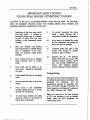
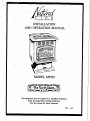
PE
AND
L
L
E
T
STOVES
INSTAT.T ATION
OPE1LATION
MANUAi.
MODEL
MP250
This equipment
must be installed by a Qualified Technician.
Read thorougly before starting installation.
Save this manual for future reference.
_a_aT
IMPORTANT
PLEASE
follow
the
installation
1.
READ
installation
inspection
Installation
with local
SAFETY
BEFORE
directions;
contact
requirements
in your
local
buil4ing
of th_s stove must comply
codes.
A building
or
: 9.
of the stove.
repairs before
instail
Never
being
restrictions
and
located
fire extl.n_dsher.
I0.
In the event of a chimney _
notify
the fire departmen t and unplug the
stove and close all openings.
11.
Terminate
.....
pellet
contact
dnmage
12.
with
tO pipe
Required
vent
pipe
so that _"
humans
or ,.pesS_l%
is avoided.
any
air
intake
or air.
outlet ports.
can resulL
Dangerous
overheating
Do not install
1"oo111-
this stove
in a sleeping
'I/4" diameter
per pound, 10%
content_
1%=3%
ash.
Corn kernels,
10,000 BTU per
15%
maximum -.. moisture
pound,
content (OptionalCornpot V_l_)
..,
block
fuel is:
pellets,
8500 BTU
maximum moisture
..............
Never
about
To provide
reasonable
fire .safety,.
install
a smoke
detector
and a
connect
stove flue to chimney
presently used by another"
heater.
o
officials
.',',
........
o
TO BURN:
conveniently
Have
your
fireplace
and ,chimney ........
system inspected by a qualified person
to installation
any necessmy
7
area,
installing.
prior
Make
:
ATFEMF17NG
installation
permit may be required.
Be sure to check
with your local
building or fire department
before
2.
NOTICE
Testing/l .isting
.
This stove
has been
in residential
o
Never
connect
the stove to an air duct
_j_tern
.
Never
stack
or
pile
combustible
materials against the stove
external vent tcrmlnation.
or around
To avoid burns, children
should be alerted to the
and adults
baTards of
high surface
temperatures.
and listed for use
construction/11
accordance
with
applicable
UL
standards,
and
for
manufactured
housing
in ao:ora_nce with
OAR
814-23-900
through
814-23-909,
by
Pacific Inspection and Research
l.aboratoty,
Inc., (PIRL)
Redmond,
WA 98052.
Based
8.
tested
of
on a tested
35:1,
air to fuel
this appliance
facility
under
the
-¢_xxiburning stoves.
ratio in _cess
is not
EPA
an
effected
regulatiens
for
I
2 Itracd_
INTRODUCTION
Read
Entire
Manual
Before
Attempting
to Burn
OVERVIEW
Gold
Your
Door
Earth Stove's
be cleaned
Gold
thoroughly
Door
with
Frame
a good
Decorative
should
window
An
cleaning solution
and a soft cloth BEFORE
the stove is burned.
Do not use any metal
polishes or abras'rees to clean the door. Any
feature
of
your
should be handed
earefuUy,
heat for a considerable
period
dropped can break. -
NaturalFtre
as they retain
of lime, and if
Placement
of the
logs
is important
in
achieving a realistic fire.
One recommended
pattern is pictured below which allows you to
Glass
Glass
is a super
heat
that withstands
continuous
1390" F. This temperature
temperatures
After long
mfistant
smve._ .....
some
Glass.
Ash Drawer
Ash Drawer
located
use a F'_-l_Ot cleaner
without
having
to
remove the logs (except for full m_;ntenance).
ceramic
temporatur_
up to •
is well beyond the
in which you oporate.your,
periods
of pilot operation
soo t may form on the
The
important
stove is the realistic fire created
by the flame
spread
F'trepot
and
the
refractory
logs.
Although
the logs are quite
durable,
they
oiLs or fingerprints
left on the Gold eodd
become
permanent
blemishe_ if the stove is
burned prior to their removal
After the first
few fires the Gold will cure.
The
Logs
in the fi'ont of the
pedestal
is designed
to make cleaning easier
by eontalnlng
the ashes
in a removable
drawer.
It is accessed
by turning the spring
loaded
screws located
on the Ash Drawer
Cover.
Do not operate
the stove with the
Ash Drawer
open or ajar.
Replace
gasket
material
as necessary to insure a tight seaL
.
I_ueffon
3
OVERVIEW
Marble
Hopper
Marble is a natural product so each piece will
have its own unique character.
'Marble
may
be cleaned with a damp cloth to remove oils
or dust.. Be sure to install the four eerawool
strips
(under the marble)
to
riot put rough objects (such as
/hopper
lids) on the surface.
the Marble before curing the
Control
Panel/Fan
The p_mary
manages
the
protect it. Do
trivets/steamers
Do not install
paint.
allows you to regulate the fuel feed rate, the
Draft Fan pilot and main power to the stove.
The Room Air Fan Rlaeo_tat allows you to
manually
regulate the fan speed except when
Three
Your
other
high speed
Pronged
stove
has
electrical
grounded
Purchasing
additional
override
is engaged.
Plug (Grounded)
a printed
circuit
components
that
board
and
require,
a
circuit
and
proper
polarity.
a surge
protector
provides
insurance
against
tmn_
problems.
Firepot
The
pellet
Firepet
burned.
Although
capability
variable
for
fuel
is where
the fuel is
it has a self cleaning
much of the
quality
(ash
ash build
content)
up,
and
extended
periods
of a low burn rate will
necensitate some manual cleaning.
An Earth
Stove
F'trepet
cleaning
tool
is
highly
recommended
(part #11300).
before
How It Works
The
Fuel Metering
Cup rotates
in the
of the Hopper providing a m_
of fuel based on the set Feed Rate.
Rheostat
Control
Board (Model
1000)
performance
of your stove.
It
the automatic
The Hopper
is where the fuel is stored
it feeds into the stove..
throat
amount
The fuel
drops into the Auger Tube where it is moved
into the Firepot.
The Draft Fan provides
combustion
air through the Auger Tube and
a series of holes in the iimer F'trepot, to allow
for complete
combustion.
The flame and hot gases provide heat
Heat Exchange Tube, located in the
chamber of the stove. The Room Air
extracts the heat and delivers it to the
to the
upper
Fan(s)
room,
along with the natural radiant heat fzom the
glass and metal surfaces.
i
_ ol_raam
OPERATION
Before
Attempting
Have
Your
Start
Up
To
Stove
Start
Pretested
Your
and
Stove,
Read
Professionally
2.
Plug in the stove.
fuel
Fill hopper with pellet.
Turn the Main Power
System"
the "Start
feed
for
five
minutes
(or
put
two cups of fuel dkectly in
the F'trepet).
Turn
the
"Stove
Main
Power
Oit _ position.
to
the
(This will stop
Switch
the
fuel
5.
Open
fire door
with the
7.
8_
As the stove
stove
and apply
F'we Starter
Close
Set
Fuel
the
position.
adjust
" 1.
2.
pusition,:then
Rate
If using
Switch to the "F_,_I
push
Switch
a remote
it to the desired
and it will automatically
Down
shut off.
go back to step two
Procedure
Turn
the Main
Fan"
position.
Thermostat,
the door.
System"
Button.
rises, the Room
gel
light..
mlnute_
door slightly ajar.
Turn the Main Power
temperature
10. If the fire goes out,
again_
Shut
to the fuel in, the Firepot,then
Allow the fuel to bum for five
o
Installed.
the desired setting.
During
the start up
procedure
or when running
the stove on
a "Low" Fuel Rate Setting, the Room Air
Fan Rhe_tat
most be in the off position.
Failure
to do so could cool down
the
position
approximately
appro'Amately
4.
Thoroughly.
Air Fan(s) will automatically
engage..
At
that point, adjust the Fuel Rate Switch to
Switch to the "F_,_M_
Provide starting fuel by pushing
Button"
and allow
fuel
to
.
Manual
Procedure
.
.
This
the
Start
to the
"Full"
Thermostat,
.room temperature.
Power
turn
If
Switch tO the _Draft
using
the Thermostat
a
remote
down.
When
the fire in the Firepot
goes out
completely,
shut the Main Power Switch
to the "Stove Off' position.
_5
OPERATION
Control
Board
Model
1000
D.
A.
Main
Power
Start
Switch
Depre_
the Start Button to allow fuel
to feed for appromaately
12 minutes
(used
during
the start up of the
The Main Power Switch is a three way
toggle with the following positions:
1. Stove Off
2. Draft Fan - allows the Draft
Fan to operate
shut down.
3. Feed
B.
System
alone
- Stove
during
to the
-
continuously.
2. Medium
the
fueL
feed
fuel
approximately,two
then two minut_
feed
fuel
minutes
Off.
on.
3. LOW - wlTll feed applu=[mamly
one
minute
on then
three
mlnut(_
C.
Off,
Draft Fan Switch
The Draft Fan
Switch
controls
the
amount
of air used
and aids in the draft
for combustion
of the stove. It
can
following
be
set
to
the
three
positions:
1. High - r_,-_ at 75% of capacity
when stove is not feeding
fueL
2. Low - runs
when stove
at 50% of capacity
is not feeding fueL
3. Off - rum
when stove
at 0% of capacity
is not feeding fueL
NOTE:
Draft
The
at 100%
feeding
reached
of capacity
Fan will run
during
the
of fuel after the stove has
normal
operating
temperatures.
E.
On/Off Light
On/Off
Light
bHnL_ to indicate
electricity
is flowing
Primary Control Board.
three
will
.
The
following
will
stove).
On
Fuel Rate Switch
The Fuel Rate
Switch controls
amount of time the burner feeds
It can be set
positions:
1. Full
Button
E
through
the
F_
The
Fuse
protects
the
Primary
Control Board from power "surges or
spikes".
(3.
Room Air Fan Rheostat
The Room Air Fan Rheostat
• used to vary
the
speed
can be
of the Room
Air Fan by r0tat/ng
it to the desired
setting.
When the stove is very hot,
the Rheostat
override
(Fan Speed
Disc) vdll automatically
run the fan on
high until the stove cools.
¢
a Ot,era_m
OPERATION
Normal
Operating
Sounds
Optional
Heat Exchange
Tubes - As the Room
Air
Fan(s) increase
in speed, you may hear air
being forced through these tubes and out into
the room.
Thermostatic
Control
Disc,
There
are
One way
convenience
the
Feed
clinking
heard.
Auger/Cap
on the hlsh setting.
The
as the fan speed is varied.
System
Hopper
to
sound
the
Auger
or the fuel
Motor(s)
may ,hear the
these motors.
- When
- When
intermittent
fuel is fed from
Tube,
a
light
being .cut may be
feeding
buzz
ma,x,lmiT_, the
of your stove
efficiency
and
is to install a
remote Thermostat.
A Honeywell
volt Thermostat
is recommended..
Follow
Tg7F
24
fuel, you
or hum
of
Draft Fan - This motor runs at various speeds
to provide combustion air to the F'trepot (and
to aid in the draft of the flue). The speed
this motor will increase
with the feeding
fueL
of
of
the
manufacturer's
installation
iustruetions
using 18/2 stat wire.
The leads
from the stove are the yellow wires found
behind
Room
Air Fan(s)
The
modern,
high
efficiency
fan may have a hum or pulsating
Auger
to
Thermostat
four
different
heat activated
temperature
discs on
the stove. The discs can make a light clicking
sound as the stove heats up or cools down.
sound, particularly
sound may change
Remote
the Primary Control
Once you have installed
Fuel Rate Switch should
Board.
the Thermostat,
the
be set to "Low'. This
will be the rate the stove will pilot at when
the Thermostat
is not calling for heat.
Product
ii
ii
i
i
r r
]
ul i i
.... • .
_:.
....
INSTALLATION
MP250.
The cornpot
• removing
REMOVAL
•This
back
the
part
front
i illl
skirt.
The
If you
wish
side
angles
OF ASH
is secured
illl
ii
ill
1ill
Support
i i i i
ii
ii
,,,,
,,,,,,
, ,,,
,
._.. ..:.,
.. ...:.:..
......_.
_ o:_.__:.:..
, _ _:_...........
:_,
N _::_
_N:'_:. . _:N_!_:_:_.
CORNPOT
ash skirt
which
ii i
._.._
_::._.._ • _:
_o._.
INTO
will not fit into models
corn.
and
i ii
_ _
& Technical
corners
i
OF P/N15169C
the ash
steeper
Warranty
.
(p/n15169C)
for burning
with
i ii
Bulletin
will
MP35/50
is a nonfunctional
a replacement
allow
MODELS
ash
skirt
fit of this
MP35/50
and MP250
&
without
part and is not necessary
( for
model
cornpot,
MP35/50
contact
your
only)
regional
Department.
SKIRT:
in place
pulling
lip of the ash
with
up until
skirt
it may
silicone
and is easily
the silicone
be necessary
breaks
removed
loose.
by grabbing
To break
to pry upward
with
-
on
a screwdriver:
TOP VIEW
ASH S KIP, T
the seal
the
Opm-at/oo 7
BURNING.
Natural
of tom
CORN
(Optional)
Fire pellet stoves will bum most types
with the addition of a Corn Pot kit.
It is not ne_zsat 7 to mix corn with wood
pellets however, wood pellets are required to
start the tim.
NOTE:,
Burning treated seed
corn is never
The Corn
1
1
1
retommended.
: ,
Pot kit consists
of.:
mounting
t3an_e of the Corn Pot over
Auger Housing and replace screw(s).
Air Shutter
should be set at 1/2 open
selector
on "LOW'.
combkstion
Shutter
flame.'
air
accordingly
Because
necessary
in order
torn,
the
primary
on
the
the
Draft
Fan
and the Draft
If more
or
Fan
less
is needed,
adjmt
to achieve
combustion
and sides with air holes because burning corn
forms a fluld-ll'ke residue which becomes
solid,
instances a white calcium
stove must be shut down
To install the Corn Pot, simply remove the
screw(s) from the top of the Auger Homing
and lift up and out on the Firepot.
Slide
the
burning
takes place on a bed at the bottom
of the
Corn Pot. The Corn Pot has a solid bottom
when cooL
The Corn Pot cleaning
will
depend upon the qua!ity and quantity.of.corn
being used. The Compot
should be cleaned
when the build up starts to reach the bottom
air holes inside of the Cornpot.
You vftl
need
to remove
the ash, and in some
1/8" Filler Plug
3/8" F'_er Plug
Corn Pot
Initially
When
the
Air
like deposit.
The
and cooled before
cleaning.
Corn
burning should be done in top vent
installations
only.
If the installation
must
elbow into a wall thimble, the horizontal run
should not be more than 24". The use of a
wall mounted
suggested.
Start
Up
Thermostat,
part #Ci'K140
is
Procedure
a bright yellow
corn size and density varies, it will be
We recommend
staring
pellets because
can be difficult
corn h_._ a dense shell that
to start.
Manually fill the
a corn fire with wood
to cah'brate the Fuel Metering
to maintain rated
BTU input
Cup
and
Compot,
to the bottom
with wood pellets..Use
prevent
ovetfiring.
This
requires
imtallation
of the Filler Plug in the
Metering
Cap. _ Use the 3/8" filler
the
Fuel
plug
feature is not recommended
when
initially
starting the unit for corn burning." (See "Start
provided
in the Cornpot
The moisture
content
15%
and care
ensure
or less,
that
there
kit..
of the
corn should
should
be taken
are no foreign
objects
be
to
in
the corn (i.e. stock st_J_, cob parts, etc.).
of the Auger Tube,
of the Start Button
Up Procedure" in the Operation
additioaal
start up information)
section
for
.
.
.
..
•
• ••
[
:•+=
:•••;
•• (
::
i :"•:i
....
8M.a/m
MAINTENANCE
Ash
Removal
Creosote
and Disposal
Fotmation
and
Need
for
very
little
Removal
CAUTION:
BE SURE
AND
STOVE
IS
REMOVING
ASHF_S!
YOUR
DRAWER
STOVE
OPEN.
THE PIRE IS OUT
COLD
BEFORE
NEVER
BURN
W[n-I
TIIE
ASH
Ashes can hold live embers for several days,
and must be disposed
of with care.
Be
cert,l,
the fire is out before you remove the
Ash Drawer.
Brush .ashes into the Ash
D_awer.
After
the Ash Drawer
emptying, clean and replace
and tighten the spring loaded
screv_.
_
place ashes in a cardboa_rd
box or any other
combustible
receptad_
Place the ashes in a metal container with a
tight fitting metal lid. The dosed container
should be stored on a noncombustible
surface,
away from combustible
mate_4at__ Keep the
ashes in the closed container
until you are
certain all the cinders have complemly cooled.
Replace
Ash Drawer
Gasket
if it becomes
dama_a_gd.
Door
•
fiberglass
gasket (3/4" in diameter)
the
seal around
the fuel door.
diameter
temperature
adhesive.
is properly
adjmted,
creosote
will develop in your flue s_tem.
If
creosote
begim
to develop,
it is _
that
poor adjustment
orneeded
maintt_-nance is
causing incomplete
combustion
of,the
fueL
Be sure your Draft Fan Switc_
and Draft
Fan shutter are set properly.
Soft fly ash is a normal by product of burning
pellet fuel, and can accumulate
in your flue
system.
Using lower grade fuel will increase
the frequency of cleaning that will be needed.
Check your flue regularly (at least once a
month) until a schedule can be established
your installation
and fuel quality.
Remember,
during
high
use
increase your inspection cycle.
periods
for
to
paint
Your stove n.t, lt is, a hi# temp paint that
Should
this become
flayed or d,ma_
it
should be replaced.
Spun tiberOass
"rope"
gasketing
can be purehused
from your dealer
or some hardware stores. It must be the
same
stove
•
+Gasket
A spun
provides
If your
as the
(RTV)
ori_nal_
silicone
Use
sealer
high
as _an
requires
time and temlxaature
to completely
cure. Depending
on your me, this may take
a few hours or a few days. Do not attempt
to repaint
the stove
unu3 the paint is
completely
cured. Do not place anything on
the stove surface until the stove h_ gone
through several heat up/cool down cycles, as
the paint will become soft before it cures.
Fan(s)
WARNING:.
MAINTAIN
THE
DOOR
SEAL IN GOOD
CONDITION:
DO NOT
At least once each year, check the Room Air
and Draft Fans inlets fDr depmits
f_om
T+I_.AkVE _
THE DOOR
USE
ANY
STOVE
BURNING
WITH
OPEN OR AJAR.
DO NOT
TYPE
OF
ABRASIVE
carpeting, pet hair, furniture
covering% etc.
Use a brush and/or light vacu.m_
for
cleanin_
Offing the fans is not necessary.
CLFANER
PLATING.
OR
POLISH
ON
GOLD
•
.....
• •
).
.
.•
%:: :.._
,
. _,:_.
,-,
_ _'• _:_:
g
.,_".
..:
.,,.
.,l'
..•
.
•,_..
.
.
.
.
, ,..•
J-,,•
•
MAINTENANCE
Firepot
Keep
the
Hrepot
• obstructions
inner
(buildup).
holes
free
Pull the Ftrepot
impurities
clinkering.
fuel
not
removed
fueL
with
and
the
or
.
Remove the F'n'epot by removing strew(s)
from the auger housing and pulling up and
out. Back out bolt on Clean Out At_e_
Plate and remove.
Silica
other
.
Remove
can fuse under heat and cause
Clinkering
is a function of the
the stove.
A cl;.k_
should be
Logs
The fallowing
of your logs:
steps
Never
will insure the. longevity
attempt
Use
a "Natural
and empty
x_hes into
6. After the stove chimney has been swept,
the top/rear chimney seal off plate needs
to be pulled off of the stove to vacuum
the unit out.
to hAncll_ them
they are hoL
2.
Ash Drawer
your nonoambmtible
container. _
of
ashes
_ previnusly
descn'bed
(see ash
removal
and
disposal).
Clean
any
remnining
ash from the Fn'ebox and Ash
Drawer area.
using a clean out tool
Refractory
°
of the
along
CAREFULLY
remove the decorative logs
fi'om the Fhebox
and set them aside.
Remove the Baffle Plate.
and
empty it when this _
The q, mlity
quantity
of pellets
used will dictate
IleCt_ry
de_nin_.
Remove
clinkers
carbon build up.
Clinkers are a byproduct
(or dirt) in the fue_
.
of
There
FETe" Flrepot
tool (Part #1000)
fxom the Fn'epoL
can do thk without
is a upper
Baffle
Plate
(see page
10) between,
the
top of
the Heat
Vxchange Tubes and the top of the stove.
Fly ash will ac_'mnulate on this plate and
cleaner
to remove ashes
In many cases you
removing any logs.
• must be removed or your flue will become
clogged- You should also remove the dust
and fly ash which accumulates
on the
F.x_pt when cleanln_ out the bottom
of the stove, do not remove the large
Heat Exchange
Tubes.
1/4 Lo_
Cleaning the MP250
.
Turn the unit off two to three
before
cleaning
cool (see
?_
to allow
Shut Down
the
houri
unit
to
procedure).
Place protective floor covering
the f_ont of the stove.
around
7.
Vacuum
the Clean
Out
&
Reinstall
your Fmepot
A er_
being sure that the
. Auger Tube pmtmd_
about 1/8" into the
F_epot.
Replace
baffle and dean out
access. Reseal and secure stove chimney.
The necessary fi-equency of thi_ pxxx:edure
will be dictated by the quality and q,,_*nqty of
the fuel burned.
• .
,
• -
..
,
,_
. :
...
,lOA_n_na_e
.Clean
Out
i;.:
:
.... _ ,_,.-
:i!_i_i)'_.ili_:¸_ il ';, •
.. :-=_,,
,,,,,
,,::
,_
_..--=
Access
1°
Ash Drawer
•
l
0
l
I
-.:_-".
.....
_
,-7-'
_
_"
_'_;"
_-
-_,
.,i_"_t'_
",_'
"_
-"
'.
'
"
Mahl_aance
11
MAINTENANCE
Maintenance
As
w/th
all appliances,
efficiency.
periodic
We recommend
maintenance
an annual
for ever_ ton of fuel burned, use a
and remove
all dust and fly ash
from
Heat.
Tubes
Remove
them
and
clean
the
chimney,
cap
F'Lrepot.
fi'om
Firebox.
and exhaust
Keep
F.
buildup.
Inspect
Maintenance
Problem::
I:_-reas¢'
Solution:
incomplete
combustion.
See maintenance
points
Decrease
velocity.
Solution:
See maintenance
in
Room,
output
point
Door
H. Replace
needed.
Ash
Gasket.as
Dia_er
Stove
Solution:
smokes
See maintenanoe
and H (above).
needed.
Door
Gasket
as
Problems
Problem=
Flames
Solution"
See maintenance
and E (above).
Problem:
Noticeable
appear
tO burn la='ly.
points
A, B, C,
Fan(s)
chan m_ in
Room
Air
Fan(Onoise.
D (almw).
See =-;-*_---ce
Problem:
remove
or
A, B, C,
Air
If remote
Thermostat
is used,
cover and clean contacts annualS.
G. Replace
Related
D and E (above).
Problem:
cage on Draft Fan annually.
passage
monthly.
heat
cage on
and Baffle
way annually or as needed.
in
at optimum
operating
Points
E. Clean squirrel
inner•
air
holes
free
Remove
ashes from the
Clean
keep
by a q_,alified
D. Vacuum air intakes and squirrel
Room Air Fan(s) annually°
areas.
B°
to
service
Maintenance
brush
Exchange
is required
maintenance
Recommended
A. Once
Suggestions
or odor in home.
point D (above).
If solutions fail to cure problem,
Shooting Section.
points A, B, C, G
o
See
Trouble
12/ns_//m_m
INSTAl
,1,ATION
Recommended
Pre-lnstaUation
NOTE TO INSTAIJFR:
installed it is recommended
Procedure
Before the unit is
that the unit be
.
pro-burned
to verify the'operation,
to burn
off oils that are sometimes
found in the Heat
Exchange
Tubes, and to eurcthe.painL.
The
-Fre-Imtallation
Procedure" should be done in
a well ventilated area as follows.
Remove the Baffle Plate from
and place it on shelving inside
°
l.x_ok down into the Hopper, and make
sure nothing
is obstructing
the Fuel
Metering
Cup. Pour 1/4 bag of pellets in
the
6.
Hopper.
With
the Main
Power
Switch in the "Feed
System" position,
push the Start Button.
Allow fuel to feed for app_;mately
five
minut_.
Put the Main Power Switch in
the pallet
the stove.
the
The shelving
is located below the Heat
Exchange Tubes.
Make certain the Baffle
plate is pushed
all the way to the right
hand side of the unit and not centered.
"Stove
Off"
position.
Apply
non-
volatilefighting material to the pellets
and fight it with a match.
Let the fuel
burn for five minutes
leaving the door
slightlyajar.
2.
Plug
the
stove
into
a grounded
outlet.
(Using a circuit _ter,_@
the electrical
outlet
for proper
ground
and polarity
where the unit will be installed.
Failure
to do so could
electrical
result
in damage
components
and
7.
Check
and
set the Main
Power
the
will increase (a full flame will need to be
establishedin the Fh'epet beLore.normul
the shutter
on the
make sure it is set
installed
the actual
upon the draft of
Draft
Fan
and
at 1/2 open(once
setting will depend
the flue.)
On the
Primmy Control
Board, A) set the Main
Power Switch from "Stove Off= to the
"Draft Fan" position and B) put the Fuel
Feed Rate on "Full".
The Draft Fan
should
door
position.
Push the Start ButtonThe
Draft Fan will run at high and the flame
warranty.)
.
the
Switch to the "Feed System" position, and
the Fuel Rate
Switch
to the "Full"
to the
. void
Close
now start.
Open
the door,
operationcan be maintained.
8.
Once
running,
operating
9.
for 15-30
observe
the
stove
minutes.
As the stove temperature rises, the Room
Air Fan(s) wRI automatically be engaged.
Set the Rheostat
m the des'Lred speed.
place
your hand over the Firepot and see if the
Draft Fan is foreiug air into the VmepoL
Turn
the Main
Power Switch
to the
10. If necessary,
adjust
the Draft Fan Shutter
m bring the fire to a bright yellow flame
(approximately
1/2 open).
"Stove Off" position.
.
Turn
the
Room Air Fan(s)
fan(s),
turn
"On" to see
Rheostat
rua.
After
the Rheostat
if the
checking
"Off'.
the
11. Once the stove is operating properly,
complete
filling the Hopper and run the
unit for 30 minutes.
CLEARANCES
The
termination
of the
outside
the pellet stove shall be kr_ated
_th the following:
,
2.
of
in accordance
Higher than 3 ft. above any forced air
inlet (air conditioner,
eta) located within .
10 ft.
Not less than 4 ft. below,
fi'om
or 1 ft. above
(door,
.
chimney
window,
4 ft. horizontally
any gravity
air inlet
Not less than 2 ft. from
building and not less than
an adjacent
7 ft. above
grade when located
sidew_ll_
(a__c__s).
to the public
adjacent
Minimum Clearances.to
Combustibles
Side:
BackFront-
12"
I"
48" horizontal
Offsets
allowed=
Floor
Protection
.
.
!
©
12" _
f_3m door
Single Wall pipe: 9"
Maximum horizontal run:
3
•
48"
36"
2
If placing units on a combustible
surf-,-e,
floor protection
is required in a residential
installation
It is required for mobile homes.
It is not
required
protection
stove.
extend
,!
etc.).
although,
beyond
that
the
the
body
floor
of the
1
14 Irtn_ll_on
INSTAI3
Venting
.ATION
If burning
corn,
direct
approved installation.
Requirements
IMPORTANT_.!
Never
vent
is
turn the
not
Draft
an
Fan
There are several options for the installation
and venting of your pellet stove.
Refer to
clearance_
before installing your.stove..
.
Selector
to the "Ot_t _" position
on am, direct
vent installations.
Keep the Combustion
Fan
Connect
only one •flue per appliance. _ When
vassing
through-walls
or
ceilings,
The
manufacturer
recommends
that elearancns
are
maintained
in accordance
with NvPA
211.
application,
Do not
chimney.
Your
downsize
your
connecting
pipe
or
Switch on the Primary Control Board in the
"Low" or High" position
In the event of a
loss of power in a rear vent direct term;nation
you will experience
dissipate rapidly.
1.
NaturalF'tre
pellet
stove
must
be
connected
to a 4" pipe. UL listed pellet vent
is a preferred
type of pipe, or a single wall 26
gauge
minimum.
Follow
the
pipe
manufacturers
installation
instructions
and
clearance.
All pipe joints, must be sealed
with the compound supplied with the pipe or
a RTV
silicone
with a rating
of at least
570 "F.
You may connect
vent to the top
screws to secure.it
silicone
with
inter'am
to provide
Direct
the single wall or pellet
of the stove using three
m the collar.
Use a RTV
a rating
of at least
a complete
570"F,
or
seaL
Vent
recommend
that to eliminate
the possl'bility of
siding
discoloration
and/or
to
enhance
performance
in bad draw situations,
the
outside
flue should be installed
with a "T',
and Pellet
the cave.
Vent chimney
Terminate
2.
3.
4.
5.
pipe run up through
the pipe using the
standard clearance.
Exception:
if using a UL
listed Pellet Vent pipe you may use the Pellet
Vent manufacturer's
clearances.
is not present
smoking,
but
and
thin will
Remove the louvered
panel to acc_,_s the
top vent outlet.
Place
the cover
plate
(A)
over
this
opening.
Make sure the gasket (B) is in
place
and
there
is a complete
seaL
Replace belts and tighten
Remove the rear vent cover flange located
on the back of the stove.
In its place, install the gasket
(13) and
starting collar (C) making sure the gasket
center has been cut out to allow flue gas
to pass through the collar.
Replace bolts
and tighten.
Attach section of pellet vent pipe (13).
Seal this connection
with high temperature
silicone sealant.
The horizontal
run may
not exceed 36 inches.
A rear
dealer,
Although
a direct vent flue is an approved
installation,
the
manufacturer
does
natural draft
breach kit b avagahle
part number RBKSO.
the
A) top
starting collar.
vent
A) Top Vent
Cover
B) Gasket Material
C) 4" Starting Collar
D) 4" - 24" section
E) 4" Wall Thimble
F) 4" Rain Cap
cover
Plate
through
your
It consists of
plate,
and
C)
4"
INSTAI I ATION
Direct
Vent
Connection To A Masonry
Through A Wall
I
Chimney
Be sure to verify
the construction
of a
masoniy chimney,
as many have combustt'ble
Follow
fammln_
the
pipe
manufacturer
clearances.
g
All ovenized
chimney
or high altitude
may
result
in less than
optimum
performance.
Installations
into a large, masonry
chimney
may require a liner to improve performance.
The use of single wall flex or rigid (26 gauge
gal_niTed
or stainless steel) pipe as a liner is
approved.
A)
Connection
Chimney
To An Existing
Class A
You may use a single wall or pellet vent pipe
from the stove top to chimney system.
An
/
E)
adaptor
can be used to make the connection
from 4" pipe to existing UL chimney
system.
D)
Verify
pipe
with
the
pipe
manufacturer
that
brands will interconnect.
into a large UL chimney system
a liner to impr6ve performance.
may require
The use of
single wall flex or rigid (26 gauge
or stainless steel) pipe as a liner
UL class
"A" chimney
is approved.
Standard
The most
desirable
pipe connected
run up through
above the roof
clearances
listed
installation
is Pellet
Vent
to the top of the stove and
the ceiling, then terminating
line.
Be sure to follow all
by the
pipe manufacturer.
your
Installations
gal_nD_!
through
a
76 Ins_/,_on
INSTAl
,1.ATION
Mobile
Home
Installation
Requirements
Installation
must
of the MP250
follow
the
in a mobile
instructions
installation,
with the
requirements:
for
home
residential:
followingsupplemental
Outside
Air Provision
Although
this section
home
local-
t.
2.
Offsets
permitted:
Ma.,6mum
4-
The
stove
must be grounded
mobile home trailer frame with
(minimunl)
5.
The
the
solid
combustion
outside
to the
a No. 8
conductor.
air must
commlulicate
to -
air.
Floor
protection beneath the unit .is
required,
but does not have to extend past
.
.
the
.
body of the
Structural
floor
while
stove.
members
such as roof trusses
joists cannot be cut
making the installation.
or
or
modified
a mobile
Set the stove in its installed position
select the floor or outside wall location
and
for
the outside
air penetration.
The
dueting must connect
with the bottom
air
of
the motor cabinet
of your
rigid or flexible 3" duet.
two offr, e_.
The ehlmney
must provide for a section
joint so that any parts extending
above 13'
6" from ground
level can be removed
for
transportation
of the mobile structure.
.
to
iustallatiom.
Use the manufaeterers
optional
outside air kit (part #85-35)
or equivalent.
No single wall pipe may be used.
Pellet
Vent pipe must be used.fi'om
stove top to
termination.
.
appfies
installation,
it may also be required by
eodus
in
standard
residential
2.
Cut
an
Opening
for the
0'm #85-35).
3.
Install
the outside
air kit.
stove,
outside
using
air
kit
I_on
INSTAl .TATION
Installation
Direct
Vent
Termination
i
Direct
Vent
Using
A "1"
•
Applications
17
NOTES
SIX
STEP 'TROUBLESHOOTING
Tools
Essential
1. Stove
For
Installation
2. Circuit
Tester
and Operation
time
to clean the
not printed
Step
or equivalent).
attempting
is wired
stove;
any troubleshooting;
properly
4) Note
(use circuit
the model
on the face of the primary
number
control
1) Check
tester);.
board,
#1
Room
Fan
System
Cheek
your
2) Check
outlet to see that you do have
the flue for blockage;
of the primary
control
it is a model:
Emerson.)
Step
Air
Only)
I/8" (p/n # 15068).
Before
and the outlet
Technicians
Mar_ual.
# 22-101
3. Molex Pin Extractor,
4. Volt Meter.
power
(Qualified
Troubleshooting
(Micronta
ATTENTION:
GUIDE
board
(ira
3) Take
model
the
number
is
#2
Confirm
Power
to
Primary
Control
Board
Turn
the
rheostat
"ON".
In this
operate
at full
• front
out.
of the room
fan(s)
room
r_ceives
air fan(s)
described),
connections
Should
step
in finding
(using
or other
been
fan(s)
your
will
hand
in
to confirm
that air is coming
of the knob will slow the
On the lowest
approximately
65 volts.
on and operates
of the
air fan(s),
setting
problem
air fan(s)
fail to come
a circuit
small
appliance
that
air fan .motor
the leads
from
to a 115v
run, the problem
into the outlet).
there
is power
can be checked
the molex
power
or simply
connector
source.
is a loose
(as
fall to run, replacement
power
to the "DRAFT
light
comes
control
switch
board.
there
If the light
"OFF"
position
If the red indicator
to
theprimary
does not come
on, check
the following:
C. High
limit
manual
D.
limit
auto reset
wiring
on, the first
the power
plug a lamp
it has
to the outlet,
by removing
If the room
the
is power
disc,
Once
from
FAN" position.
on,
A. Power
B. Fuse
and connecting
connection.
main
will not be
is to check
tester
Turn
If the
properly
fan speed
the.problem
determined
air fan(s)
air
Place
air fan(s).
the room
them
room
it is now
or circuitry.
the room
source
the
source
room
it "clicks",
(l15v).
comes
the
the rheostat,
till
position
speed
of the air outlet
Further
rotation
speed
the
knob
air fan(s)
High
source
If the fuse
reset
not
and
proper
contact.
power
at the
indicates
115v
wig be necessary.
18 ¸¸
discs
disc
and the high
"popped
be
out",
certain
Then, using
power
switch.
to replace
limit manual
inspect
the
pins
the molex
are
a volt meter,
If
and the red indicator
it will be necessary
board.
If the room
reset
is not blown
disc has
connectors
(see Step #1)
the
making
check
volt
light
the primary
for
meter
is not on,
control
SIX STEP TROUBLESHOOTING
GUIDE
Step #3
Confirm Draft Fan Operation
• B.
Set the main power switch to the "DRAFT FAN" position
then set the fuel rate switch to the "FULL" position.
The
draft fan should now operate at full power (apro_c115v).
During the tEot_ng process, the draR fan will operate at
C.
To check the daft fan when the stove is cold, check for
movement
of air by placing your hand in or near the
firepot If the movement of air is not obvious, inspect the
dmR fan to be ceaain the air shutter is open. If the air
shutter is open and the dratt fan is not running, check it by
Step #4
Inspect
Fuel
in Step # 1, paragraph
Cup
2.
for Blockage
cup, FIRST:
THE POWER
CORD.
• NEVER PUT YOUR FINGERS
CAVITY OF THE METERING
IN _
CUP.
FUEL
Remove all the fuel from the hopper. Reach down inside
the hopper and rock the fuel metering cup back and forth
(being careful not to put fingers in fuel cavity of metering
cup). The cup should move approximately
1/4" in either
direction. If it does not move, something is jamming
it
(usually a foreign object) and _ll have to be removed by
using one of the following methods:
A.
A or B fail_ to clear the obslrucfion,
Set the main power switch to the "FEED SYSTEM"
position.
Press the "START'
button. Both the cup and
auger motor should start. If the motors run but the fuel
metering cup and/or auger does not turn, check the cast
iron coupler on the ends of each motor shaft to make
certain the set screw is tight on the flat part ofthe shatL If
the motors are not running, use a volt meter to check for
line voltage (115v) at the molex cotmector or cheek them
obstruction
(between
the
metering cup and the blade).
fuel
cavity
of
Step #6
Re-light
The
in Step # 1, paragraph
2.
Stove
Follow the normal
start, check
attached.
the
vity
.
x-Obstruction
described
Note: Anytime you are checking the motors, you should
verify the speed at which the motors are turning. This can
be accomplished
by timing the revolution of the coupler.
Using the set screw as a reference point, the bottom motor
(auger) will make app, oximat_!y one revolution in 10
seconds. The top motor (cup) will make a_v_oximately
one revolution every 48 seconds.
Using a tool, such as a slotted
screw driver, clcarthe
BladeJ
If procedures
by using the procedure
Metering
To inspect the fuel metering
• UNPLUG
Locate the metering cup motor cooling pmpellor on
the back of the appliance and turn it by hand in the
reverse direction until the metering cup rotates
back far enough to clear the obsuh'ction.
Step #5
Confirm Cup and Auger Motor Operation
Voltage
70-75v
60-65v
0v
using the procedure
Only)
then remove the metering cup motor and metering
cup to find and clear the obstruction.
thefollowingspeeds:
Switch Position
High
Low
Off
(Qua!gfied Technicians
start up procedure.
to be certain
If the unit fails to
the leads to the safety disc are
POWER
FLOW
DIAGRAM
PJI_'OSTAT
FAN SPEED
)
DISC
j_
BROWN
•
•
BLUE
:1
BLACK
BLACK
SAFRT"Y DISC
D
CUP MOTOR
n
CONTROL
BURNER
ORANGE
DRAPr
(COMBUSTION
FAN
FAN)
AUGER
MOTOR
<
)
BOARD
t
"
t
i
Otoss_
Glossary
_
of Terms
AUGER
The Auger transfers the fuel down
the Burner Tube into the Ftrepot.
MAIN
AUGER
Switch is the main switch allowingelectricity
to flow through the Pr/mary Control Board to
the components.
MOTOR
The
the Auger
to deliver:fuel
BURNER
TUBE
Auger
Motor
dr/yes
to the Ftrepot.
The
Burner
Tube
,
contains
two passageways;
one for the Auger and the
other for combustion
air. This tube supplies
both the fuel and combwsfion
air to the
POWER
swrrcFI
The Main Power
MANUAL
RF-qET
If the temperature
of the
stove reaches 200"F,
the Manual
Reset will
"POP" and stop the flow of electricity
fuel feed system.
to the
Flrepot.
MOTOR
CUP
MOTOR
The
Cup
to
Motor
drives
deliver
fuel
to
the
Fuel Metering
Auger.
Cup
DRAFT
FAN
for combustion
Pushes
air into the Firepot
and into the flue for draft.
Fan(s)
the
Rheostat
causing
Room
Air
to run at full speed.
FIREPOT
FUEL
The
FLrepot
_G
Metering
Cap meters
is where
combustion
CUP
The
the mount
delivers it down to the Auger.
deliver a set amount
of fueL
HOPPER
are stored
Fuel
the
The
and
Metering
Hopper
hmneled
Cup.
Fuel
of fuel and
The
and Burner
System
Covers
the
Fuel Feed
components.
the
FAN SPEE1) DISC
At stove temperatures
above 140", the FanSpeed
Disc activates
bypassing
CABINET
cup will
is where the pellets
down to feed the
SAFETY DISC At stove temperatures
above
120",
the Safety
Disc engages
to allow
electricity to flow to the fuel feed system.
RHEOSTAT
At stove temperatures below
140"F, the Rheostat
can be used to vary the
speed of the Room Air Fan(s).
SPECIFICATIONS
Approx Sq Ft Heat Capacity .........
Up to 1800 $q. Ft.
• t
Flue siz_
4" Top
Width
Depth
Overall
......
25.5"
.....
372
.
Height (w/flue collar)
33.50"
...........
19.5"
.................
12.75"
............
Ye_
Floor' Protection
Requirements
' Mobile Home
Residential
.................
..N'°.M. . °U'°*°°
Yes
Yes
Fusc
...........
3amp
Bk/Hopper
Cnlx of Flue
Floor to Rear
Outxide
Hopper
Flue Center
Air Provision
._
Capacity
Heat Input
(maximum)
.......
Ship Weight
Room
Blower
(2 e.a.)
........
Cup Motor
.................
Auger
............
.....
Draft
-
Motor
Fan
Square feet hea_ng _
are approximation*
design, ceiling heighf, ambient ou_de
'
35.5"
..........
Height
or Rear
40 Ibs
so,ooo BTU/hr
350 Lbs.
"
160 CFM
(ea)
Apprm.
.9
amI_
1 RPM
.34 amlm
Approx.
6 RPM
1.12 amps
Apprm.
60 RPM
.65 amps
truly. Theft will van/depending
temperatures and how _
s_/e
is o_.
upon ff_e levi
of ir_,e.=n'_o_,cli._u,
house
(
,
.
_tmr,
COMPONENT
DIAGRAMS
/ Top Vent
Gold
Door
Outlet
--
L_'==_
Manual
Reset
(15011)-'-'-'_i__
Room Air Fan (15007)
Safety Disc (11565)_
Manual
Re_t
Draft
Fan
e_ O_ranm 23
(15011> _
15001-1)_'-_
Hopper
_
/_l'l
_._=_[
_,"_
_'_J-_------Room
I t,_=.,-_-lF1---_-4
)
[_
Air Fan (1.5009)
[[ffl]_[=_=i_
_-j
]
J
_uge
Rear
ivlotor
Vent
(15003)
Outlet
,9
- Motor
,
•
,,
Cabinet
Control
-Rhe_tat
Board
(15022)
(02082)
i
_'2"_
Peter
Card
(021171)
24 w_/
NaturalFire
limited
TM
Warranty
To b_e OFgGINAL PUBCHASEB ol an applianee dudng b_ pee_d of warran_ covemge _
_,
_ _
_
the apprmace to be free of defect8 in .,,_=,_al end wo,;_,,_hip.
_
warmmy give_ you specific righ_ and you may have o#_r
Hgh_ which vary fmm Mate _o swJ_ Some states MAY NOT ALLow =helimita_ons ot exclusions set fort below SO THE LIMITA770NS
OR EXCLUSIONS MAY NOT APPLY TO YOU..
ALL PARTS am waffar_ad 100%_f_ one.year from d_a.of
purchase for any defects in mm_riats or _p;
.
....
_
PAl_
em wan'ar_md for _o yenn_ [mm da_
_ pu_t_
_r eny de_c_ ln m_v_s
or worlenan_p.
The _cond
year covemge ts lxo_atad _t SO_ based on
b_e cummt m_T pdc_
. No repair o_ m_
costs mTI be _
without
b_e PRIOR APPROVAL of b_e _
or the
manufacturers au_oK_d
dearer. Approval is ob_ined by
mtawdng _a defec_e pate at PURCHASERS EXPENSE, to
the man_s
_
dealer for lnspectlon pHor to
repa/r o¢ mptc=',_rm_
Thts wawan_ DOES NOT include or
cover the coct of lnspecgon or labor itwo/ved M removing or
mplacing a d_
part_ all of which muM be bome by _ne ,
ALL PART_ tg_.PT
elec_cal
components, logs, _,
gasket, fimpoes, baffles and.paint e_e warranted for five.
This
years from date ol p_
for any defects in .,,_iaJs
or
wodcnanship. Pm-rated coverage for yeam two b_mugh five
is e_ follow_
Year2
Year 3
Yeas4
Year5
All pm_a_
warranty
80% ccwemge
60% coverage
40%coverage
20%coverage
is based on the the_ cumsnt m_Jl p#ce.
This appliance MUSE. BE INSTAl I _n BY A QUALIRED
INSTAt I FR in accordance'with .inr_uc_o_ .furnished with,, •
your appliance.
WE SHALL NOT BE UABLE FOR INCIDENTAL OR C_V3EQU_
OR DAMAGE EICEPT AS SET FORTH ABOVF.
_
IMPORTANT: This warranly is not mF_d unless b_e watran_ rs_L_M;_n
days ol the data of pumhase.
Earth
S.W.
Tualatin;
ddec_
in
material
and
card has been propedy completed and mailed wi_in 30
Author_ed
Serial Numbec.
10595
to
OR COMMB_CIA LOS_, NOR FOR ANY OTHER L_
Fory_xa'racoltts:
The
limited
All o#mr wan'arNes, e._m_ed,
implied or stabJtory,
including warmr_e_ of rHne_ for a pa_ffcular purpose of
me_ility
am condiffoned upon compliance with _he
fo#ov_ng _
abedam UMITED TO a period ending ONE.
YEAR af_r _be odcjir_l reta# p_,2._
_ter which b_em are
no mmedie_ which-extend beyond _e descrlp_n
on the.
face hemel.
warranty coverage during yearn two through five
Date PumJmsed:
Model Number:
is
_p,.and
it do_
not apply m loss or damage
which is _e result of accident, misuse, negligence, improper
instaJla#cw or any o#mr _,_e occurring afar delivery Io the
ORIGINAL PURCHASEP= No person Is _
to extend
or erd_je any li_b#/ty or obllgaUon _
we may ha_,_ in
connecdon w#h the sale ol U_is ap_iance.
Stove,
Manhasset
OR
Inc.
Street
97062
WIRING
NaturalFire
DIAGRAM
TM
Pellet
"
Stove
Wiring Diagram
Control
Board
-White
= Black
- Red
_
* Graywires to control board
arcfor factory testing only.
[
_
& (c)
115 Volt A.C. Power Supply
must have proper polarity.
(p) _
Yellow _
_'enow
_
T87F
_
I
Th_o_at
_-O
"_
I I,q* /t
II
'';/
_
O.l
\
,I
-(c)
.
,.
m
/
_
_
(c)
Models with
2 Blowers
Green(Ground)
w_it,(C)
(P)
Black
(c)
PJp[le
'
(P)
(P)
(c)
Fan Speed
Rheostat
_
Control
-Brown (P)k
--
?
- Black
(C) m
Black
re)
molex
saf_ Disc
Common
= C
Power = P
SERVICE
Service
Date
AND MAINTENANCE
Service
Technician
Service
Description
LOG