1
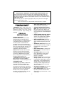
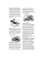
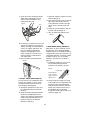
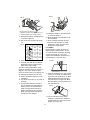
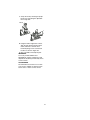
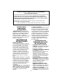
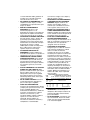
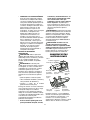
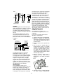
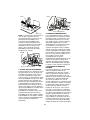
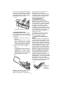
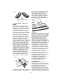
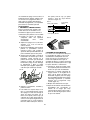
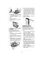
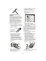
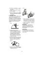
Operator’s Manual
PLATE JOINER
Model No.
900.277303
CAUTION: Read and follow all
Safety Rules and Operating
Instructions before First Use
of this Product.
•
•
•
•
•
Safety
Operation
Maintenance
Parts List
Español pg. 14
Sears, Roebuck and Co., Hoffman Estates, IL 60179 USA
Form No. 631088-00
AUG05
ONE YEAR FULL WARRANTY ON CRAFTSMAN PROFESSIONAL TOOL
If this Craftsman Professional tool fails to give complete satisfaction within one
year from the date of purchase, RETURN IT TO ANY SEARS STORE OR PARTS
& REPAIR CENTER OR OTHER CRAFTSMAN OUTLET IN THE UNITED STATES
FOR FREE REPAIR.
This warranty gives you specific legal rights, and you may also have other rights
which vary from state to state.
Sears, Roebuck and Co., Dept. 817WA, Hoffman Estates, IL 60179
IMPORTANT SAFETY
INSTRUCTIONS
• KEEP WORK AREA CLEAN. Cluttered
areas and benches invite injuries.
• CONSIDER WORK AREA ENVIRONMENT. Don't expose power tools to rain.
Don't use power tools in damp or wet
locations. Keep work area well lit. Do not
use tool in presence of flammable liquids
or gases.
• GUARD AGAINST ELECTRIC SHOCK.
Prevent body contact with grounded
surfaces. For example; pipes, radiators,
ranges, and refrigerator enclosures.
• KEEP CHILDREN AWAY. Do not let
visitors contact tool or extension cord. All
visitors should be kept away from work
area.
• STORE IDLE TOOLS. When not in use,
tools should be stored in dry, and high or
locked-up place - out of reach of
children.
• DON'T FORCE TOOL. It will do the job
better and safer at the rate for which it
was intended.
• USE RIGHT TOOL. Don't force small
tool or attachment to do the job of a
heavy-duty tool. Don't use tool for
purpose not intended.
• DRESS PROPERLY. Do not wear loose
clothing or jewelry. They can be caught
in moving parts. Rubber gloves and nonskid footwear are recommended when
working outdoors. Wear protective hair
covering to contain long hair. Air vents
often cover moving parts and should
also be avoided.
• USE SAFETY GLASSES. Also use face
or dust mask if operation is dusty.
• DON'T ABUSE CORD. Never carry tool
by cord or yank it to disconnect from
receptacle. Keep cord from heat, oil, and
sharp edges.
WARNING: When using electric tools,
basic safety precautions should always be
followed to reduce risk of fire, electric
shock, and personal injury, including the
following:
READ ALL
INSTRUCTIONS
DOUBLE INSULATION
Double insulated tools are constructed
throughout with two separate layers of
electrical insulation or one double thickness
of insulation between you and the tool's
electrical system. Tools built with this
insulation system are not intended to be
grounded. As a result, your tool is equipped
with a two prong plug which permits you to
use extension cords without concern for
maintaining a ground connection.
NOTE: Double insulation does not take
the place of normal safety precautions
when operating this tool. The insulation
system is for added protection against
injury resulting from a possible electrical
insulation failure within the tool.
CAUTION: WHEN SERVICING USE
ONLY IDENTICAL REPLACEMENT
PARTS. Repair or replace damaged cords.
POLARIZED PLUGS
Polarized plugs (one blade is wider than
the other) are used on equipment to
reduce the risk of electric shock. When
provided, this plug will fit into a polarized
outlet only one way. If the plug does not fit
fully into the outlet, reverse the plug. If it
still does not fit, contact a qualified
electrician to install the proper outlet. Do
not change the plug in any way.
2
• SECURE WORK. Use clamps or a
vise to hold work. It's safer than using
your hand and it frees both hands to
operate tool.
• DON'T OVERREACH. Keep proper
footing and balance at all times.
• MAINTAIN TOOLS WITH CARE. Keep
tools sharp and clean for better and
safer performance. Follow instructions
for lubricating and changing accessories.
Inspect tool cords periodically and if
damaged, have repaired by authorized
service facility. Inspect extension cords
periodically and replace if damaged.
Keep handles dry, clean, and free from
oil and grease.
• DISCONNECT OR LOCK OFF TOOLS
when not in use, before servicing, and
when changing accessories, such as
blades, bits, cutters.
• REMOVE ADJUSTING KEYS AND
WRENCHES. Form habit of checking
to see that keys and adjusting
wrenches are removed from tool
before turning it on.
• AVOID UNINTENTIONAL STARTING.
Don't carry tool with finger on switch. Be
sure switch is off when plugging in.
• EXTENSION CORDS. Make sure your
extension cord is in good condition.
When using an extension cord, be sure
to use one heavy enough to carry the
current your product will draw. An undersized cord will cause a drop in line voltage resulting in loss of power and
overheating. The following table shows
the correct size to use depending on
cord length and nameplate ampere
rating. If in doubt, use the next heavier
gage. The smaller the gage number, the
heavier the cord.
• OUTDOOR USE EXTENSION CORDS.
When tool is used outdoors, use only
extension cords intended for use
outdoors and so marked.
• STAY ALERT. Watch what you are
doing. Use common sense. Do not
operate tool when you are tired.
• CHECK DAMAGED PARTS. Before
further use of the tool, a guard or other
part that is damaged should be carefully
checked to determine that it will operate
properly and perform its intended
function. Check for alignment of moving
parts, binding of moving parts, breakage
of parts, mounting, and any other
conditions that may affect its operation.
A guard or other part that is damaged
should be properly repaired or replaced
by an authorized service center unless
otherwise indicated elsewhere in this
instruction manual. Have defective
switches replaced by authorized service
center. Do not use tool if switch does not
turn it on and off.
ADDITIONAL SAFETY INSTRUCTIONS
CAUTION: Wear appropriate personal
hearing protection during use. Under some
conditions and duration of use, noise from
this product may contribute to hearing loss.
WARNING: Some dust created by power
sanding, sawing, grinding, drilling, and other
construction activities contains chemicals
known to cause cancer, birth defects or other
reproductive harm. Some examples of these
chemicals are:
• lead from lead-based paints,
• crystalline silica from bricks and cement
and other masonry products, and
• arsenic and chromium from chemicallytreated lumber (CCA).
Your risk from these exposures varies,
depending on how often you do this type of
work. To reduce your exposure to these
chemicals: work in a well ventilated area,
and work with approved safety equipment,
such as those dust masks that are specially
designed to filter out microscopic particles.
Minimum Gage for Cord Sets
Volts
Total Length of Cord in Feet
120V
0-25
26-50
51-100
101-150
240V
0-50
51-100
101-200 201-300
Ampere Rating
More
Not more
AWG
Than
Than
0610
12
6
10
-12
-16
18
18
16
14
16
16
16
12
16
14
14
12
14
12
Not Recommended
• Avoid prolonged contact with dust
from power sanding, sawing,
grinding, drilling, and other
construction activities. Wear
3
protective clothing and wash
exposed areas with soap and water.
Allowing dust to get into your mouth,
eyes, or lay on the skin may promote
absorption of harmful chemicals.
WARNING: Use of this tool can generate
and/or disburse dust, which may cause
serious and permanent respiratory or other
injury. Always use NIOSH/OSHA approved
respiratory protection appropriate for the
dust exposure. Direct particles away from
face and body.
OVERVIEW
You have purchased a precision woodworking tool. The function of the plate
joiner is to enable you to make extremely
strong and accurate joints in wood and
wood by products.
The tool works by a plunging action to
precisely cut crescent shaped slots for the
placement of flat wooden dowels or
"biscuits" like those shown in Figure 2.
FIG 3
SAVE THESE
INSTRUCTIONS
FIG 1
EDGE TO EDGE JOINT
"T" JOINT
Lock knob
CORNER
JOINT
Paddle switch
45° FRAME JOINT
Lock on
button
Dust
exhaust port
Adjustable
fence
Anti-slippage pin
Lock
knob
1/2"
(12.7 mm)
2-3/8"
(60 mm)
3/8"
(9.5 mm)
2-3/16"
(56 mm)
#20
Plunge
depth
adjustment
knob
OFFSET JOINT
SWITCH
Your plate joiner has a paddle switch
located on the underside, as shown in
Figur 1. To turn the tool on, depress the
paddle switch. To turn the tool off, release
the paddle switch. To lock the tool on for
continuous operation, there is a lock on
button located at the rear ofr the tool just
below the cord. When cutting, always hold
the paddle switch and one hand on the
handle. To lock the tool on, depress
andhold the paddle switch as you depress
the lock button. Hold the lock button in as
you gently release the paddle switch. The
tool will continue to run. To turn the tool off
from a locked on condition, depress and
release the paddle switch once.
5/16"
(8 mm)
1-13/16"
(46mm)
#10
OFFSET
The various adjustments on the patented
base/fence assembly will enable you to
make virtually any biscuit joint imaginable.
The tool may be further enhanced by
some simple jigs and fixtures that can be
easily made. Some of the more common
biscuit joinery applications are shown in
Figure 3 and are discussed in detail in the
applications section of this manual.
Height
adjustment
knob
Examine Figure 1 and your plate joiner for
a few minutes to become familiar with the
various features and the names used to
describe them. The following sections will
discuss the various controls and you will
need to know where they are.
FIG 2
EDGE
MITRE
JOINT
BLADE REPLACEMENT
In time your joiner blade will wear out and
need replacement.
#0
(flat biscuits)
4
To remove the blade, follow the steps
below.
3/16" (4.76mm) and as distant as 1-3/8"
(35mm) measured from the workpiece
surface to the centerline of the blade (see
Figure 6). The adjustable angle feature
allows a full range of settings from 0° to 90
as well as a reverse 45° bevel which
allows outside registration on mitre joints.
(See Applications section under Mitre
Joints, Figure 27.)
1. Turn off and unplug the plate joiner.
2. Remove the 4 torx head screws from the
bottom of the shoe, using the T20 torx
wrench provided.
3. Rotate the shoe out of the way.
4. Use the spanner wrench provided to
loosen (counterclockwise) the blade nut.
Depress the spindle lock pin on the top
of the gear case to hold the spindle
while you unscrew the nut.
5. Remove the blade and have it
sharpened or replace it with a
new one. (Available through Sears
service centers.
6. Reinstall the blade by reversing the
steps above. Be sure blade teeth point
counterclockwise as shown in Figure 4.
FIG 5
Adjustment
Knob
Lock
knob
FIG 4
The height adjustment is accomplished by
first loosening the lock knob on the right
side of the fence and then rotating the
knurled adjustment knob until the desired
height is reached (see Figure 5).
Tightening the lock knob will then
automatically align the fence parallel to the
blade and lock it in position. The vertical
scale and pointer located directly under
the lock knob can be used to assist in
setting this height. The scale readings
indicate distance from the blade centerline
to the fence surface when the fence is set
at 90° (see Figure 6). If the depth scale
ever needs to be adjusted, loosen the two
screws that secure the scale and move
the scale until the pointer is indicating the
proper reading (see Figure 6).
7. IMPORTANT: Always check the fine
depth adjustment when sharpening or
replacing the blade. Adjust if necessary.
(See "Controls" section).
OPERATION
THE CONTROLS
The heart of your plate joiner is the
base/fence assembly. All of the controls
that let you make a variety of precision
cuts are located on this assembly. Take a
few minutes to become familiar with the
various controls.
FIG 6
Pointer points
to 1/2" mark
CAUTION: Always turn off and unplug
plate joiner before making any adjustments.
1. ADJUSTABLE FENCE
The adjustable fence provides a sturdy,
precise reference surface to determine the
point at which the slots for the biscuits will
be cut. Its adjustable height feature allows
you to position biscuit slots as close as
1/2"
Centerline of
blade
5
2. PLUNGE DEPTH ADJUSTMENT
The depth of cut can be set to match the
dimensions of the particular size biscuit
you will be using. The numbers on the
depth adjustment knob (0,10,20,M)
coincide with the three sizes of biscuits
shown in Figure 2. The letter M stands for
the maximum depth capacity of the tool
which is 20mm (25/32"). This depth is
obtainable only with a new blade and by
backing out the fine adjustment screw (see
next section).
the opening as shown in Figure 8. Turn
the depth adjustment screw clockwise for
less depth and counter-clockwise for
increased depth. Each full turn causes a
change in depth of 1mm (0.04"). Always
check the depth adjustment by first making
test cuts in scrap wood.
FIG 9
FIG 7
Anti-slippage pin
20
M
0
10
4. ANTI-SLIPPAGE PINS
Plate Joiners tend to slide to the right with
respect to the workpiece when making a
cut. This tendency is increased with a dull
blade or when plunging very rapidly. Antislippage pins have been provided to
reduce this tendency and are located on
the front registration surface on either side
of the blade opening slot. When making
some joints, you may wish to retract the
anti-slippage pins so as not to scratch
your workpiece in a visible area. For this
purpose, simply rotate the anti-slippage
pins approximately 1/6 of a turn and they
will retract back behind the front
registration surface. A flat blade
screwdriver can be used to rotate the pins
as shown in Figure 9.
Red mark
NOTE: The M setting has been provided
for future use and will not be necessary for
most biscuiting operations. To select a
depth, align the appropriate number with
the red mark scribed in the tool's housing,
as shown in Figure 7. Rotate the depth
adjustment knob to the desired position
and it will "click" into place.
FIG 8
5. BOTTOM REGISTRATION SURFACE
For certain applications, you will want to
use the bottom surface of the plate joiner
for alignment. When using the bottom
registration surface, the adjustable fence
should be set to 0°. The height setting is
unimportant. This surface is used primarily
when making 'T' joints (see applications
section). The distance between the
centreline of the blade and the bottom
registration surface is fixed at 3/8" (9.5mm)
which allows centreing on 3/4" (19mm)
thick stock. The 3 red marks on the bottom
registration surface indicate the centreline
(or the deepest point) of the biscuit cut and
R
Fine depth adjustment
3. FINE DEPTH ADJUSTMENT
You may encounter situations where you
want to leave a little looseness in your
joint so that you can move it slightly before
the glue sets. For these instances a fine
depth adjustment has been provided. To
adjust, you must first raise the adjustable
fence to its uppermost position. Then
insert the T20 torx wrench provided into
6
the approximate width of a #20 biscuit so
that you'll know where the edge of the
blade is and can prevent breakthrough. To
avoid breaking through the workpiece,
align the shoe so that neither outside mark
extends beyond the end of the workpiece.
If either side does, there is a good chance
that the blade will break through the
surface and ruin your work.
exhaust port on the right rear of the tool. To
clean out, turn off and unplug the tool and
remove packed dust. The bag will hold the
dust generated from approximately 70 to
100 #20 biscuit cuts before filling up.
GENERAL OPERATION
Plate joiners are primarily used for making
cabinetry and furniture, joining millwork or
other similar applications where a strong,
accurate joint is required in wood or wood
byproducts. There are literally hundreds of
variations of joints that can be made with
your Plate Joiner. We will limit our
discussion to six basic joints (see application section) that can be used to build on
and adapt to your own applications.
FIG 10
The following are some basic set-up steps
that will apply to all biscuit joints.
1. BISCUIT SIZE SELECTION
As mentioned earlier, the three biscuit
sizes are #0, #10 and #20. It is a good
rule of thumb to use the largest biscuit
size that will physically fit in the
application. Unless you are joining narrow
face or picture frames or using 1/2" or
thinner stock, you will find the #20 biscuit
size to suit most applications. After
selecting the biscuit size, set the depth
adjustment knob to the corresponding size
(see Controls section). Also, be sure the
fine depth adjustment is correctly set by
first testing in a scrap piece. This is
extremely important as you do not want to
discover during glue-up that your biscuit
slots are not quite deep enough.
Vacuum hose connection
6. DUST EXTRACTION
There are two options provided for
collecting dust from your plate joiner as
described below.
A. Dust Adaptor (See Figure 10)
This attachment, when inserted as
described above, allows the use of
several common sizes of vacuum hose
to be attached for direct vacuum pickup of the dust.
FIG 11
FIG 12
Protruding biscuit
end (Trim off with
saw and sand
smooth)
FIG 13
B. Dust Bag (See Figure 11)
The dust bag provided fits snugly over
the dust adaptor described above. To
empty the bag, open the zipper
underneath and dump dust out.
NOTE: When the bag becomes full, the
dust will back-up into the adaptor and the
1" or greater stock thickness
7
2. BISCUIT LOCATION AND LAYOUT
Generally, biscuits may be spaced and
located at your discretion. For edge joints, a
good rule of thumb is to space biscuits
every 6-10 inches on centre. It is further
recommended that biscuits be placed so
that the centreline of the end biscuits is
2-3 inches from the end of the workpiece.
When joining face frames or picture frames
where the workpiece is narrow, you may
have to choose the smaller biscuit sizes to
keep from "breaking out" on the end of the
joint. Breaking out should be avoided if
possible, but if not you can assemble the
joint and trim off the exposed biscuit tip after
the glue sets (see Figure 12). When working
with material up to 1" thick, we advise to use
a single biscuit located in the approximate
centre of the material thickness. If thicker
stock is to be joined, you may choose to
use 2 biscuits across the thickness for
greater strength (see Figure 13). Biscuit
locations should be marked by first
positioning the mating pieces exactly as
they are to be assembled.
3. MAKING THE CUT
Prior to making any cut, be sure that all
fence adjustments are set and lock knobs
are tight. Also, be sure you have selected
the proper depth setting. Clamp your
workpiece firmly and align the plate joiner's
centre registration mark with your layout
mark. Turn on the tool and let the blade
come up to full speed (approximately 1
second). Grasping the paddle switch and
handle and positioning the fence firmly and
squarely against the workpiece, plunge the
blade until it bottoms against the stop.
Continuing to hold the tool squarely and
firmly, allow the return spring to retract the
blade from the work and then release the
switch to shut the tool off. It will take some
practice to obtain a "feel" for the tool to
produce accurate joints, so practicing in
scrap wood first is advisable.
4. JOINT ASSEMBLY
After your joints are cut, you may wish to
trial fit everything together before gluing.
When you are satisfied with your joints,
evenly spread any good quality woodworking glue in each slot as well as on
the mating flat surfaces of your joint. Place
biscuits in the slots, assemble the joint
and clamp until dry. For a biscuit joint to
be most effective, it is important that the
biscuits themselves be in contact with the
glue. This is because the biscuits absorb
the moisture in the glue and expand to
form a tight joint.
FIG 14
Next, make a mark at 90° to the joint
interface across both pieces at the desired
biscuit locations (see Figure 14). See
Application section for more specific
information on joint layout. The marks you
make will then be aligned with one of the
centre registration marks on the tool,
again, depending upon your specific
application.
APPLICATIONS
1. EDGE TO EDGE JOINTS
This is the simplest to make and most
common joint for the plate joiner. Follow
the steps below to produce this joint.
A. Prepare the workpieces and lay them
on a work surface exactly as they are to
be assembled.
B. Spacing biscuits 2-3" in from the ends
and 6-10" apart, lay out the biscuit
centres.
C. Set up the plate joiner by first selecting
the proper depth setting. Set the fence
to 90°. Set the height adjustment to
position the biscuit in the approximate
centre of the stock thickness.
FIG 15
2"-3"
6"-10"
8
mortise and tenon joint. Figure 18 shows
two types of frame joints. Follow the steps
outlined below.
FIG 16
A. Arrange the workpieces on a flat work
surface exactly as they are to be
assembled.
B. Select the proper biscuit size based on
the length of the joint. If the frame
pieces are too narrow for a #0 biscuit,
you will have to allow the biscuit tip to
protrude slightly. Then trim the tip off
after the joint is dry (see Figure 12).
C. Lay out the biscuit locations.
D. Set up the tool by selecting the depth
that corresponds to the chosen biscuit
size. Lock the fence at 90° and adjust
the fence height to centre the biscuit on
the stock thickness.
D. Clamp the workpiece and position the
tool so that the centre indicator mark
lines up with the first layout mark (see
Figure 16). Turn on the tool and make
the plunge cut. Retract the tool and
release the paddle switch to turn the
tool off. Repeat for each layout mark.
E. Glue, assemble and clamp the joint.
FIG 17
3/16" Minimum
FIG 19
3/16" Minimum
3/16" Minimum
E. Clamp the workpiece and position the
Plate Joiner to make the first cut (see
Figure 19).
F. Turn on the tool and make the plunge
cut.
G. Repeat for each layout mark.
H. Glue, assemble and clamp the frame.
F. For stock thicker than 1", you may wish
to use double biscuits at each location.
Set the height adjustment to allow at
least 3/16" of stock between the biscuit
and the edge of the work surface. Make
all cuts at this fence setting before
readjusting the fence for the lower cuts.
Again, there should be at least 3/16" of
stock between the biscuit and the
outside wall and between the biscuits
themselves (see Figure 17).
FIG 20
FIG 18
3. CORNER JOINTS (SEE FIGURE 20)
Corner joints are another common and
excellent application for biscuit joinery.
Follow the procedure below.
2. FRAME JOINTS
Frame joints are an ideal application for
biscuit joinery. With the plate joiner you
can create a very strong, precise joint that
is much faster to make than a dowel or
A. Arrange the workpieces exactly as they
are to be joined.
B. Select the biscuit size and layout the
biscuit locations.
9
C. Set up the tool by selecting the proper
depth setting, adjusting the fence to
centre on the stock thickness and
setting the angle to 90°.
C. Clamp the workpiece, align the tool and
make the plunge cut.
D. Next, adjust the fence up by an amount
equal to the desired offset. Use the
scale and pointer located on the right
side of the tool under the fence lock
knob.
E. Clamp the second workpiece, align the
tool and make the plunge cut.
F. Glue, assemble and clamp the joint.
FIG 21
FIG 23
D. For this joint, you will make cuts into the
edge of one workpiece and the face of
another. The edge cut is performed the
same as for edge to edge joints. The
face cut is made by clamping the
workpiece and aligning the tool as
shown in Figure 21. Turn the tool on,
make the plunge cut and repeat for
each layout mark.
E. Glue, assemble and clamp the joint.
5. EDGE MITRE JOINTS (FIGURE 23)
Edge mitres are most commonly used in
box structures or for making multisided
pedestals where you would like to hide the
end grain. Once again, biscuit joinery is an
outstanding method to use both for added
strength as well as ease of assembly.
Follow the steps below to assemble a
90° joint.
FIG 22
A. Position the workpieces as they are to
be assembled and layout biscuit
locations on the outside of the joint.
FIG 24
Inside edge
Position biscuit
closer to inside
edge to increase
dimension "A"
4. OFFSET JOINTS (SEE FIGURE 22)
You may wish to have a deliberate offset
between two workpieces. This is easily
accomplished with your plate joiner by
performing the following steps.
A
B. Set up tool by first setting fence angle
to 90°. Make the fence adjustment such
that the biscuit is located toward the
inside of the joint where the material is
thicker, then select the biscuit size so
that the blade does not protrude
through the outside wall when the cut is
made (see Figure 24).
A. Arrange the workpieces as they are to
be assembled and layout the biscuit
locations.
B. Set up the tool by selecting the proper
biscuit size and adjusting the fence
angle to 90°. Select the workpiece that
will be set back and adjust the fence
height to centre the cut within the
thickness of that piece.
10
FIG 27
FIG 25
Reverse 45° bevel: Allows outside
registration on mitre joints (NOTE: The tool
is registered against the outside surface.)
D. Clamp the workpiece and align the tool
as shown in Figure 27.
E. Make the plunge cut and repeat for all
biscuit locations.
F. Glue, assemble and clamp the joint.
G.For joints other than 90° see Inside
Registration column in Figure 26 for
proper fence angle setting.
6. T-JOINTS
Biscuit joining is a viable alternative to
dadoing when making a T-joint. T-joints
are most commonly used when attaching
shelves to the sides of a case. The
method described below will work if your
shelf material is at least 5/8" thick.
C. Clamp the workpiece and align the tool
as shown in Figure 25.
D. Turn on the tool and make the plunge
cut.
FIG 26
#
OF SIDES JOINT ANGLE
FENCE ANGLE SETTING
OUTSIDE REGISTRATION INSIDE REGISTRATION
90
4
5
6
8
108
120
135
90
45
81
54
75
60
67.5
67.5
FIG 28
E. Glue, assemble and clamp the joint.
F. For joints other than 90° see Outside
Registration column in Figure 26 for
proper fence angle setting.
The above method will produce a joint
where the outside surfaces of the joint are
aligned. If you wish to produce a joint
where the inside surfaces are aligned, use
the following procedures for a 90° joint.
A. Place the workpieces on a work surface
exactly as you will be assembling them
in the form of an upside down "T." Mark
lightly along the joint where the top of
the shelf will go (see Figure 28). Mark
biscuit locations at the joint interface on
the shelf piece only.
A. Position workpieces as they are to be
assembled.
B. Lay out biscuit locations on the inside of
the angle.
C. Set up tool by setting fence angle to
45°. Set vertical fence adjustment so
that the biscuit is located toward the
inside of the joint where material is
thicker. Select biscuit size so that the
blade does not protrude through the
outside face of the material.
FIG 29
B. Lay the shelf down on the mating
workpiece. Clamp the two workpieces
together and to the work surface in this
position (see Figure 29).
11
C. Set up the tool by selecting the proper
biscuit size and setting the adjustable
fence angle at 0°.
FIG 30
D. Using the bottom registration surface,
align the tool with the biscuit location
marks and make a vertical and a
horizontal plunge cut for each biscuit
location as shown in Figure 30.
E. Glue, assemble and clamp the joint.
IMPORTANT
To assure product SAFETY and
RELIABILITY, repairs, maintenance and
adjustment should be performed by Sears
service centres.
ACCESSORIES
Recommended accessories for use with
your tool are available for purchase from
Sears stores or Sears service centers.
12
13
CRAFTSMAN HEAVY DUTY PLATE JOINER — MODEL NUMBER 900.267303
14
PARTS LIST
The model number will be found on a nameplate attached to the handle. Always
mention the Model Number in all correspondence regarding your Heavy Duty
Plate Joiner or when ordering repair parts.
CRAFTSMAN HEAVTY DUTY PLATE JOINER — MODEL NUMBER 900.267303
UN AÑO DE GARANTÍA COMPLETA PARA LAS HERRAMIENTAS
CRAFTSMAN PROFESSIONAL
Si esta herramienta Craftsman Professional no funciona a la entera satisfacción del
cliente dentro del año de la fecha de compra, DEVUÉLVALA A CUALQUIER
TIENDA SEARS O A UN CENTRO DE REPARACIÓN Y REPUESTOS U OTRO
PUNTO DE VENTA DE PRODUCTOS CRAFTSMAN EN LOS ESTADOS UNIDOS
PARA RECIBIR UNA REPARACIÓN GRATUITA.
Esta garantía le concede derechos legales específicos; pueden existir otros
derechos que varían según el estado.
Sears, Roebuck and Co., Dept. 817WA, Hoffman Estates, IL 60179
Instrucciones
Importantes
de Seguridad
CLAVIJA POLARIZADA
Se emplean clavijas polarizadas (con una
pata más ancha que la otra) para reducir
los riesgos de choque eléctrico. Cuando
el cordón eléctrico cuente con este tipo de
clavija, ajustará en un contacto polarizado
solamente de una manera. Si la clavija
no ajusta completamente en su contacto,
inviértala. Si aún así no ajusta, llame a un
electricista calificado para que le instale
un contacto polarizado apropiado. No
modifique o haga cambios en la clavija
por ningún motivo.
ADVERTENCIA: Es indispensable
sujetarse a las precauciones básicas de
seguridad, con la finalidad de reducir el
peligro de incendio, choque eléctrico y
lesiones personales, en todas las
ocasiones en que se utilicen herramientas
eléctricas. Entre estas precauciones se
incluyen las siguientes.
LEA TODAS LAS
INSTRUCCIONES
Instrucciones de
Seguridad para todas
las Herramientas
DOBLE AISLAMIENTO
Las herramientas con doble aislamiento
se han elaborado de manera integral con
dos capas separadas o una capa de
espesor doble de aislamiento eléctrico
entre usted y el sistema eléctrico que
contienen. Las herramientas elaboradas
con este sistema de aislamiento no
requieren conectarse a tierra. Como
resultado, su unidad esta equipada con
una clavija de dos patas que le permite
emplear cordones de extensión sin
preocuparse por tener una conexión a
tierra.
NOTA: El doble aislamiento no substituye
a las precauciones normales de seguridad
cuando se opera esta herramienta. La
finalidad de este sistema de aislamiento
es ofrecer a usted protección añadida
contra la lesión resultante de fallas en el
aislamiento eléctrico interno de la
herramienta.
PRECAUCION: UTILICE SOLAMENTE
REFACCIONES ORIGINALES CUANDO
HAGA SERVICIO A SU HERRAMIENTA.
Reemplace los cordones eléctricos
dañados.
• CONSERVE LIMPIA LA ZONA DE
TRABAJO. Las superficies y los bancos
con objetos acumulados en desorden
propician los accidentes.
• OTORGUE PRIORIDAD AL AMBIENTE
DE TRABAJO. No deje las
herramientas eléctricas expuestas a la
lluvia. No las utilice en lugares
inundados o mojados. Conserve bien
iluminada la zona de trabajo. No use la
herramienta en presencia de líquidos o
gases inflamables.
• PROTEJASE CONTRA EL CHOQUE
ELECTRICO. Evite el contacto corporal
con superficies aterrizadas, por ejemplo,
tuberías, radiadores, antenas y
gabinetes de refrigeración.
• CONSERVE APARTADOS A LOS
NIÑOS. No permita que los visitantes
toquen las herramientas o los cables de
extensión. Los visitantes deben estar
alejados del área de trabajo.
• GUARDE LAS HERRAMIENTAS QUE
NO EMPLEE. Las herramientas que no
15
•
•
•
•
•
•
•
•
se están utilizando deben guardarse en
un lugar seco y elevado o bajo llave,
fuera del alcance de los niños.
NO FUERCE LA HERRAMIENTA. Esta
cumplirá su función mejor y con más
seguridad bajo las especificaciones para
las que se diseñó.
EMPLEE LA HERRAMIENTA
ADECUADA. No fuerce a una
herramienta pequeña o a sus
dispositivos de montaje en un trabajo de
tipo pesado. No emplee la herramienta
en una tarea para la que no se diseñó.
VISTASE DE LA MANERA ADECUADA.
No tenga puestas ropas o artículos de
joyería flojos, pues podrían quedar
atrapados por las partes móviles de las
herramientas. Se recomienda el empleo
de guantes de caucho y calzado
antiderrapante cuando se trabaja al aire
libre. Cúbrase bien la cabeza para
sujetarse el pelo si lo tiene largo.
COLOQUESE ANTEOJOS DE
SEGURIDAD. Póngase también una
mascarilla contra el polvo si lo produce la
operación de corte que va a efectuar.
TENGA MUCHO CUIDADO CON EL
CORDON ELECTRICO. Nunca levante
la herramienta por el cordón ni tire de
éste para desconectarlo del enchufe.
Apártelo del calor y los objetos calientes,
las sustancias grasosas y los bordes
cortantes.
SUJETE FIRMEMENTE LOS OBJETOS
SOBRE LOS QUE TRABAJE. Utilice
prensas o tornillos de banco para sujetar
bien los objetos sobre los que va a
trabajar. Esto ofrece mayor seguridad
que sujetar los objetos con la mano, y
además deja libres ambas manos para
operar la herramienta.
NO SE SOBRE EXTIENDA. Conserve
en todo momento bien apoyados los
pies, lo mismo que el equilibrio.
CUIDE SUS HERRAMIENTAS.
Conserve sus herramientas bien afiladas
y limpias para que funcionen mejor y con
mayor seguridad. Obedezca las
instrucciones de lubricación y cambio de
accesorios. Inspeccione los cordones
eléctricos con frecuencia y, si los
encuentra dañados, hágalos cambiar o
reparar en un centro de servicio
autorizado. Revise también con
frecuencia las extensiones eléctricas y
reemplácelas si están dañadas.
16
•
•
•
•
Conserve los mangos secos, limpios y
libres de aceites y grasas.
DESCONECTE LAS HERRAMIENTAS
O ASEGURELAS EN POSICION DE
APAGADO. Hágalo cuando no las
emplee, antes de darles servicio y
cuando vaya a cambiarles accesorios
como seguetas, discos, brocas, etc.
RETIRE LAS LLAVES DE AJUSTE Y
OTRAS HERRAMIENTAS DE MANO.
Adquiera el hábito de asegurarse de que
se han retirado las llaves de ajuste de la
herramienta antes de accionarla.
EVITE QUE LA HERRAMIENTA SE
ACCIONE ACCIDENTALMENTE.
Nunca sostenga una herramienta con el
dedo en el interruptor. Asegúrese que el
interruptor está en la posición de
"apagado" antes de conectarla.
CORDONES DE EXTENSION.
Asegúrese que su cordón de extensión
esté en buenas condiciones. Cuando
utilice un cordón de extensión,
asegúrese de usar uno con el calibre
necesario para soportar la corriente que
su producto necesita. Un cordón de
extensión de menor calibre al necesario
ocasionará una caída en el voltaje de la
línea, produciendo pérdida de potencia y
sobrecalentamiento. La tabla 1 muestra
el calibre correcto para utilizarse de
acuerdo de la longitud del cordón y el
amperaje nominal que se encuentra en
la placa de identificación del producto. Si
tiene dudas, utilice el calibre inmediato
superior. Mientras más pequeño es el
número del calibre, mayor capacidad
tiene el cordón.
Calibre mínimo para cordones de extensión
Volts
Longitud total del cordón en metros
120V
0-7.62 7.63-15.24 15.25-30.48 30.49-45.72
240V
0-15.24 15.25-30.48 30.49-60.96 60.97-91.44
AMPERAJE
Más No más
Calbre del cordón
de
de
0 - 6
18
16
16
14
6 - 10
18
16
14
12
10 - 12
16
16
14
12
12 - 16
14
12
No Recomendado
• CORDONES DE EXTENSION PARA
INTEMPERIE. Cuando trabaje a la
intemperie, utilice siempre cordones de
extensión diseñados exclusivamente
para esta finalidad.
• NO SE DISTRAIGA. Concéntrese en lo
que está haciendo. Recurra al sentido
común. No opere ninguna herramienta
si se encuentra fatigado.
• VERIFIQUE LAS PARTES DAÑADAS.
Antes de seguir empleando cualquier
herramienta, es indispensable verificar
con mucho cuidado que las guardas u
otras partes dañadas puedan operar de
la manera adecuada para cumplir con
su función. Verifique la alineación de las
partes móviles, la firmeza con que
deben encontrarse sujetas en sus
montaduras, las partes rotas, las propias
montaduras y cualesquiera otros
detalles que pudieran afectar a la
operación de la herramienta. Las
guardas y las otras partes que se
encuentren dañadas deberán repararse
bien o cambiarse en un centro de
servicio autorizado, a menos que se
diga otra cosa en el manual del usuario.
Haga que se cambien los interruptores
dañados en un centro de servicio
autorizado. No emplee ninguna
herramienta que tenga inutilizado o
estropeado el interruptor.
REGLAS DE SEGURIDAD
ADICIONALES
PRECAUCIÓN: Utilice la protección
auditiva adecuada durante el uso de esta
unidad. Bajo ciertas condiciones y duración
de uso, el ruido producido por este
producto puede contribuir a la pérdida
auditiva.
ADVERTENCIA : Parte del polvo
creado al lijar, aserruchar, moler o perforar
con máquina, así como al realizar otras
actividades de la construcción, contiene
substancias químicas que se sabe
producen cáncer, defectos congénitos u
otras afecciones reproductivas. Algunos
ejemplos de esas substancias químicas
son:
• plomo de pinturas a base de plomo,
• sílice cristalizado de ladrillos y cemento y
otros productos de albañilería, y
• arsénico y cromo de la madera
químicamente tratada (CCA).
El riesgo al contacto con estas substancias
varía, según la frecuencia en que se haga
este tipo de trabajo. Para reducir la
exposición a esas substancias químicas:
trabaje en un área bien ventilada, y trabaje
con equipos de seguridad aprobados, tales
como máscaras contra el polvo
especialmente diseñadas para filtrar las
partículas microscópicas.
• Evite el contacto prolongado con el
polvo procedente del lijado, serrado,
esmerilado y taladrado eléctricos, así
como de otras actividades del sector
de la construcción. Lleve ropa
protectora y lave con agua y jabón las
zonas expuestas. Si permite que el
polvo se introduzca en la boca u ojos o
quede sobre la piel, puede favorecer la
absorción de productos químicos
peligrosos.
ADVERTENCIA: Toda persona que entre
al área de trabajo deberá usar una máscara
antipolvo o protección respiratoria. El filtro
debería ser reemplazado a diario o cuando
el usuario tenga dificultad para respirar.
Puede encontrar la máscara antipolvo
apropiada aprobada por NIOSH/OSHA en
su ferretería local.
PRECAUCIÓN: Cuando no se use,
guarde la herramienta en posición
horizontal sobre una superficie estable,
donde no interrumpa el paso o provoque
una caída. Algunas herramientas con
baterías grandes se sostienen sobre la
batería, pero pueden caer fácilmente.
CONSERVE ESTAS
INSTRUCCIONES
FIG 1
Perilla de seguridad
Interruptor de paleta
Botón de
encendido
permanente
Puerto de escape
de polvo
Perilla de
ajuste de
altura
Guía de
ajuste
Perno anti
derrapante
Perilla de
seguridad
Perilla de
ajuste de
profundidad
de penetración
Examine la figura 1 y su ensambladora
durante unos minutos para familiarizarse
con las diferentes características y sus
nombres. Las secciones siguientes
explicarán los diferentes controles y usted
deberá saber en donde se encuentran.
17
permanente para asegurar la herramienta
para operación continua. Este botón se
encuentra en la parte trasera de la
herramienta, justo por encima del cordón
eléctrico. Siempre que corte sujete la
herramienta con una mano en el mango
del interruptor y la otra mano en el mango
auxiliar. Para asegurar la herramienta en
posición de operación continua, oprima el
gatillo interruptor al mismo tiempo que el
botón de encendido permanente. Sujete el
botón de encendido permanente mientras
libera el gatillo interruptor. La herramienta
continuará en funcionamiento. Para
apagar la herramienta desde la posición
de operación continua, oprima y libere el
gatillo interruptor una vez.
FIG 2
1/2"
(12.7 mm)
2-3/8"
(60 mm)
3/8"
(9.5 mm)
5/16"
(8 mm)
2-3/16"
(56 mm)
#20
1-13/16"
(46mm)
#10
#0
(espiga plana)
VISTAZO
Usted ha adquirido una herramienta para
trabajo de precisión en madera. La función
de la ensambladora es permitirle hacer
ensambles extremadamente resistentes y
precisos en madera y productos derivados
de ella.
La herramienta trabaja a base de una
función de penetración para cortar con
precisión las cajas para colocar espigas
planas de madera, como las ilustradas por
la figura 2.
CAMBIO DE CUCHILLA
Con el tiempo, la cuchilla de su
herramienta se desgastará y necesitará
cambiarse.
Para sacar la cuchilla, siga los pasos
descritos a continuación.
1. Apague y desconecte la ensambladora.
2. Quite los 4 tornillos con cabeza de
estrella de la parte inferior de la zapata
con la llave de estrella T20 que le
proporcionamos.
3. Gire la zapata para apartarla del
camino.
4. Con la llave de horquilla que le
proporcionamos, afloje (en sentido
contrario a las manecillas del reloj) la
tuerca de la cuchilla. Oprima el perno
de seguro de la flecha que se
encuentra en la parte superior de la
caja de engranes para sujetar la flecha
mientras afloja la tuerca.
5. Quite la cuchilla y hágala afilar o
cámbiela por una nueva. (A su
disposición en los centros de servicio
Sears.)
FIG 3
ENSAMBLE A
MEDIA MADERA
ENSAMBLE DE
INGLETE
ENSAMBLE EN T
ENSAMBLE
DE ESQUINA
ENSAMBLE A 45˚
PARA MARCOS
RELIEVE
ENSAMBLE CON RELIEVE
Los diferentes ajustes en el montaje
patentado de la base y la guía le
permitirán hacer casi cualquier ensamble
con espigas que usted se pueda imaginar.
El trabajo de la herramienta se puede
mejorar con algunos cortes y arreglos
sencillos que se pueden lograr fácilmente.
Algunos de los tipos de ensambles con
espigas más comunes se muestran en la
figura 3 y se tratan a detalle en la sección
de aplicaciones de este manual.
FIG 4
INTERRUPTOR
Su ensambladora cuenta con un
interruptor de paleta localizado en la parte
inferior, como se ilustra en la figura 1.
Para encender la herramienta, oprima la
paleta. Para apagar la herramienta, libere
el interruptor. Hay un botón de encendido
6. Instale de nuevo la cuchilla invirtiendo
los pasos citados anteriormente.
18
Asegúrese que los dientes de la
cuchilla apuntan en sentido contrario a
las manecillas del reloj, como se
observa en la figura 4.
7. IMPORTANTE: Siempre revise el
ajuste fino de profundidad cuando afile
o cambie la cuchilla. Ajústelo de ser
necesario.
(Consulte la sección "Controles".)
El ajuste de altura se logra de la siguiente
manera: primero se afloja la perilla de
seguridad que se encuentra al lado
derecho de la guía y a continuación se
gira la perilla moleteada de ajuste hasta
alcanzar la altura deseada (figura 5).
Al apretar la perilla de seguridad se
alineará la guía en paralelo con la cuchilla
automáticamente y se asegurará en
posición. La escala vertical y el indicador
localizados directamente bajo la perilla de
seguridad se pueden utilizar para
ayudarse a hacer este ajuste de altura.
Las lecturas de la escala indican la
distancia entre la línea central de la
cuchilla y la superficie de la guía cuando
está colocada a 90° (figura 6). Si en
alguna ocasión se requiere ajustar la
escala de profundidad, afloje los dos
tornillos que la aseguran y muévala hasta
que el indicador apunte hacia la lectura
debida (observe la figura 6).
OPERACION
LOS CONTROLES
El corazón de su ensambladora es el
montaje de la base y la guía. Todos los
controles que le permiten efectuar cortes
en diversas posiciones se localizan en
este montaje. Tómese unos minutos para
familiarizarse con los diferentes controles.
PRECAUCION: Siempre apague y
desconecte la ensambladora antes de
hacer cualquier ajuste.
1. GUIA AJUSTABLE
La guía ajustable proporciona una
superficie de referencia fuerte y precisa
para determinar el punto en el que se
cortarán las cajas para las espigas. Su
característica de altura ajustable le
permite colocar las cajas tan cercanas
como 4,76 mm (3/16") y tan distantes
como 35 mm (1-3/8") medidas a partir de
la superficie de la pieza de trabajo hasta
la línea central de la cuchilla (observe la
figura 6).La característica de ajuste de
ángulo le permite variar las posiciones
desde 0° hasta 90° así como en ángulo
invertido de 45°, que le permite registro
exterior en ensambles angulares.
(Consulte la sección de aplicaciones,
ensambles angulares, figura 27).
FIG 5
FIG 6
El indicador apunta a la
marca de 12,7 mm (1/2")
12,7 mm
(1/2") de
la línea
central
de la
cuchilla
2. AJUSTE DE PROFUNDIDAD DE
PENETRACION
La profundidad del corte se puede ajustar
de acuerdo con el tamaño de las espigas
que piense utilizar. Los números en la
perilla de ajuste de profundidad (0, 10, 20,
M) coinciden con los tres tamaños de
espigas mostradas en la figura 2. La letra
'M' equivale a la capacidad máxima de
profundidad de corte de la herramienta,
que es de 20 mm (25/32"). Esta
profundidad se puede obtener solamente
con una cuchilla nueva y sacando el
tornillo de ajuste fino (consulte la siguiente
sección).
Perilla de
ajuste
Perilla de
seguridad
19
FIG 7
FIG 9
20
M
0
10
Perno antiderrapante
Marca roja
4. PERNOS ANTIDERRAPANTES
Las ensambladoras tienden a deslizarse
hacia la derecha con respecto a la pieza
de trabajo cuando se efectúan los cortes.
Esta tendencia aumenta con el uso de
una cuchilla sin filo o cuando se penetra
demasiado rápidamente. Los pernos
antiderrapantes se proveen para reducir
esta tendencia y se localizan en la
superficie de registro frontal a cualquier
lado de la ranura de salida de la cuchilla.
Cuando haga algunos ensambles, puede
desear retraer los pernos antiderrapantes
para no rayar la pieza de trabajo en una
zona visible. Para este efecto,
sencillamente gire los pernos
antiderrapantes aproximadamente 1/6 de
vuelta y se retraerán por detrás de la
superficie de registro frontal. Se puede
utilizar un destornillador plano para girar
los pernos, como se ilustra en la figura 9.
NOTA: La posición 'M' se proporciona en
caso de que se requiera usar y no
necesariamente para la mayoría de las
operaciones de ensamblaje. Para
seleccionar una profundidad, haga
coincidir el número apropiado con la
marca roja grabada en la carcaza de la
herramienta, como se observa en la
figura 7. Gire la perilla de ajuste de
profundidad a la posición deseada y
chasqueará en su lugar.
FIG 8
R
5. SUPERFICIE DE REGISTRO
INFERIOR
Para ciertas aplicaciones, usted preferirá
utilizar la superficie inferior de la
ensambladora para alinearse. Cuando
utilice la superficie de registro inferior, la
guía ajustable de be ajustarse a 0°, sin
importar el ajuste de altura. Esta superficie
de alineación se utiliza principalmente
para hacer ensambles en 'T' (vea la
sección "Aplicaciones"). La distancia entre
la línea central de la cuchilla y el fondo de
la superficie de registro inferior está fija a
9,5 mm (3/8") que permite centrar en
madera de 19 mm (3/4"). Las 3 marcas
rojas que se encuentran en la superficie
de registro inferior indican la línea central
(o el punto más profundo) del corte para la
espiga y aproximadamente el ancho de
una espiga del No. 20 para que usted
sepa en dónde se encuentra el filo de la
cuchilla y pueda evitar atravesar la pieza.
Para evitar atravesar la pieza de trabajo,
coloque la zapata de manera que ninguna
Ajuste fino de profundidad
3. AJUSTE FINO DE PROFUNDIDAD
Puede encontrarse con situaciones en las
que quiera dejar un poco de juego en el
ensamble para poderlo mover un poco
antes que el pegamento seque. Para
estas ocasiones, se proporciona un ajuste
fino de profundidad. Para ajustarlo, debe
levantar primero la guía ajustable a la
posición más alta. A continuación inserte
el destornillador de estrella T20 que le
proporcionamos en la abertura, como se
observa en la figura 8. Gire el tornillo de
ajuste de profundidad en el sentido de las
manecillas del reloj para menor
profundidad y en sentido contrario a las
manecillas del reloj para aumentar la
profundidad. Cada giro completo cambia
la profundidad en 1 mm (0,04"). Siempre
revise el ajuste de profundidad haciendo
cortes de prueba en material de
desperdicio.
20
de las marcas se extienda más allá de los
confines de la pieza de trabajo. Si cualquier
de las marcas sobresale, existen buenas
posibilidades de que la cuchilla traspase la
pieza y usted arruine su trabajo.
parte trasera de la herramienta. Para
limpiar, apague y desconecte la
herramienta y saque el polvo empacado.
La bolsa contendrá el polvo generado por
aproximadamente 70 a 100 cortes de
cajas No. 20 antes de llenarse.
FIG 10
OPERACION GENERAL
Las ensambladoras se utilizan
principalmente en la fabricación de
gabinetes y muebles para unir tablones, o
en otras aplicaciones en que se requieran
uniones precisas y resistentes de piezas
de madera o sus derivados. Existen
literalmente cientos de variaciones de
ensambles que pueden realizarse con su
ensambladora. Nos limitaremos a describir
seis ensambles básicos que pueden
utilizarse para fabricar y adaptarse a sus
propias aplicaciones.
Los siguientes son algunos pasos de
ajuste inicial básicos que se aplican a
todos los ensambles de espiga.
Conexión para manguera de aspiradora
6. EXTRACCION DE POLVO
Su herramienta cuenta con dos opciones
para recolectar el polvo de madera que su
ensambladora genera, como se describe a
continuación.
1. SELECCION DE TAMAÑO DE LA
ESPIGA
Como se mencionó con anterioridad, los
tres tamaños básicos de espigas son #0,
#10 y #20. Como regla práctica, es mejor
utilizar la espiga más grande que quepa
físicamente en su aplicación. A menos que
quiera ensamblar tiras angostas o marcos,
o utilice madera de menos de 12,7 mm
(1/2") de espesor, se encontrará que las
espigas #20 sirven para la mayoría de las
aplicaciones. Después de seleccionar el
tamaño de la espiga, coloque la perilla de
ajuste de profundidad en la indicación
correspondiente al tamaño de la espiga
(vea en la sección de "Controles").
También, asegúrese que el ajuste fino de
profundidad está correctamente ajustado
probando primero en una pieza de madera
de desperdicio. Esto es de extrema
importancia si no quiere descubrir durante
el pegado que las cajas para sus espigas
no son suficientemente profundas.
A. Adaptador para polvo (observe la
figura 10).
Este dispositivo, cuando se inserta
como se describe en el párrafo
anterior, permite el empleo de diversos
tamaños de mangueras de aspiradora
para la extracción directa del polvo.
B. Bolsa para polvo (observe la
figura 11).
La bolsa para polvo que viene con su
ensambladora se ajusta sobre el
adaptador para polvo, descrito
anteriormente. Para vaciar la bolsa,
abra la cremallera que se encuentra en
la parte inferior y vacíe el polvo.
FIG 11
FIG 12
Extremo
sobresaliente de
la espiga (corte
con segueta y
lije hasta alisar)
NOTA: Cuando la bolsa se llena, el polvo
se regresará hacia el adaptador y el
puerto de escape que se encuentra en la
21
que colocará las espigas (figura 15). Vea
la sección de "Aplicaciones" para obtener
información más específica sobre el
trazado de los ensambles. Las marcas
que usted haga quedarán alineadas con
una de las marcas de registro de la
herramienta, de nuevo, dependiendo de
su aplicación específica.
FIG 13
Madera de 25,4 mm (1") de
espesor o mayor
FIG 15
2"-3"
2. LOCALIZACION Y TRAZO DE LA
ESPIGA
Generalmente, las espigas se pueden
espaciar y localizar a discreción. Para
ensambles a media madera, una buena
regla práctica es espaciar las cajas entre
10 y 15 cm de centro a centro. Se
recomienda también que las espigas se
coloquen de tal manera que las espigas
finales queden aproximadamente entre 5 y
7,5 cm del final de la pieza de trabajo.
Cuando ensamble marcos en que las
piezas de madera sean muy angostas,
usted deberá seleccionar los tamaños de
espigas más pequeños para evitar
traspasar el extremo del ensamble. Debe
evitarse traspasar las piezas, siempre que
sea posible, pero si no es así, usted
puede recortar el sobrante de la espiga
después de que el pegamento seque
(observe la figura 12). Cuando trabaje con
materiales hasta de 25 mm (1") de
espesor, le aconsejamos que utilice una
espiga localizada en la parte central del
material. Si se trabajará con material con
espesor mayor, usted puede escoger
colocar dos espigas en la pieza para
aumentar la resistencia (figura 13). La
localización de las espigas debe marcarse
colocando primero las piezas a unir
exactamente como serán ensambladas.
FIG 14
6"-10"
3. CORTE
Antes de hacer cualquier corte, asegúrese
que todos los ajustes de la guía se hayan
colocado correctamente y que las perillas
estén apretadas. También, asegúrese de
haber seleccionado la profundidad
adecuada. Sujete su pieza de trabajo
firmemente y haga coincidir la marca de
registro de centro de la ensambladora con
la marca que usted trazó en la pieza.
Encienda la herramienta y permita que la
cuchilla alcance su velocidad máxima
(aproximadamente 1 segundo). Tome el
interruptor de paleta y el mango lateral y
coloque la guía con firmeza y a escuadra
contra la pieza de trabajo, haga que la
cuchilla penetre hasta que haga contacto
con el tope. Continúe sujetando la
herramienta con firmeza y a escuadra,
permita que el resorte retraiga la cuchilla
de la pieza de trabajo y libere el
interruptor para apagar la herramienta. Le
tomará algún tiempo desarrollar la
sensibilidad necesaria para que la
herramienta realice ensambles precisos,
así que mejor practique un poco en
material de desperdicio primero.
A
4. ENSAMBLADO
Después de cortar sus piezas, usted
puede probar el ajuste antes de pegarlas.
Cuando esté satisfecho con los cortes que
realizó, distribuya uniformemente
cualquier pegamento para madera de
buena calidad en cada caja, así como en
las superficies que quedarán en contacto.
Coloque las espigas en las cajas, arme la
pieza y prense hasta que seque. Para que
continuación, haga una marca a 90° de la
unión de ambas piezas en los lugares en
22
un ensamble de espiga sea más eficaz, es
importante que las propias espigas estén
en contacto con el pegamento. Esto se
debe a que las espigas absorberán la
humedad del pegamento y se expandirán
para formar un ensamble ajustado.
mm (3/16") entre la caja y la pared
exterior y entre las cajas mismas
(observe la figura 17).
FIG 17
5 mm (3/16") Minimo
APLICACIONES
1. ENSAMBLES A MEDIA MADERA
Esta es la manera más sencilla y más
común de hacer un ensamble con su
herramienta. Siga los pasos descritos a
continuación para producir este ensamble.
5 mm (3/16")
Minimo
5 mm (3/16") Minimo
A. Prepare las piezas de trabajo y
colóquelas sobre una superficie
exactamente
como
serán
ensambladas.
B. Separe las espigas a 5 ó 7,5 cm de los
extremos y 15 a 25 cm entre los
centros de éstas.
C. Ajuste la ensambladora seleccionando
primero la profundidad correcta.
Coloque la guía a 90°. Coloque el
ajuste de altura aproximadamente a la
parte central del espesor de la pieza.
D. Sujete la pieza de trabajo y coloque la
herramienta de manera que la línea
indicadora central coincida con la
primera de las líneas que usted trazó
(observe la figura 16). Encienda la
herramienta y haga el corte. Retraiga
la herramienta y libere el gatillo
interruptor para apagarla. Repita para
cada línea que usted haya marcado.
FIG 18
2. ENSAMBLES PARA MARCOS
Los marcos son una aplicación ideal para
los ensambles de espiga y caja. Con la
ensambladora usted puede crear una
unión muy precisa y resistente que es
mucho más rápida de hacer que un
ensamble de pernos. La figura 18 muestra
dos tipos de ensambles para marcos. Siga
los pasos descritos a continuación.
A. Coloque las piezas de trabajo sobre
una superficie plana exactamente en la
manera en que serán ensambladas.
B. Seleccione el tamaño adecuado de
espiga basado en la longitud de la
unión. (Si las piezas del marco son
demasiado angostas para una espiga
#0, usted deberá permitir que la espiga
sobresalga ligeramente y recortarla
después que el pegamento haya
secado (figura 12).
C. Marque la localización de las cajas.
D. Ajuste la herramienta seleccionando la
profundidad que corresponda al
tamaño de la espiga que haya
seleccionado. Asegure la guía a 90° y
ajuste la altura de la guía para centrar
la caja en el material.
FIG 16
E. Agregue el pegamento, ensamble y
prense la unión.
F. Para tablas con espesor mayor a 25
mm (1") usted puede desear colocar
dos espigas en cada zona. Arregle el
ajuste de altura para dejar por lo
menos 5 mm (3/16") entre la caja y la
superficie de la tabla. Haga todos los
cortes con este ajuste de guía antes de
reajustarla para los cortes inferiores.
De nuevo, debe haber por lo menos 5
23
D. Para este ensamble, usted hará cortes
en el borde de una de las piezas y en
la cara de la otra. El corte en el borde
se hace igual que para los ensambles
de borde contra borde. Los cortes en la
cara se hacen sujetando la madera y
alineando la herramienta como se
muestra en la figura 21. Encienda la
herramienta, haga el corte y repita
para cada caja.
E. Añada el pegamento, ensamble y
prense el ensamble.
FIG 19
E. Asegure la pieza de trabajo y coloque
la ensambladora para hacer el primer
corte (observe la figura 19).
F. Encienda la herramienta y haga el
corte.
G. Repita para cada caja.
H. Añada el pegamento, ensamble y
prense el marco.
FIG 22
FIG 20
4. ENSAMBLES EN RELIEVE
(OBSERVE LA FIGURA 22)
Usted puede decidir dejar un relieve
deliberadamente entre dos piezas. Esto
se puede lograr con facilidad con su
ensambladora realizando los siguientes
pasos.
3. ENSAMBLES DE ARISTA (OBSERVE
LA FIGURA 20)
Los ensambles de arista son otra
aplicación perfecta para nuestra
herramienta. Siga los pasos descritos a
continuación.
A. Coloque las piezas en la forma en que
las va a ensamblar y trace la
localización de las cajas.
B. Ajuste la herramienta seleccionando el
tamaño de espiga adecuado y
ajustando la guía a 90°. Tome la pieza
que será colocada como respaldo y
ajuste la altura de la guía para centrar
el corte dentro del espesor de esa
pieza.
C. Sujete la pieza de trabajo, centre la
herramienta y haga el corte.
D. A continuación, ajuste la guía hacia
arriba en la medida que desee hacer el
relieve. Utilice la escala y el indicador
que se encuentran al lado derecho de
la herramienta debajo de la perilla de
seguridad de la guía.
E. Sujete la segunda pieza, centre la
herramienta y haga el corte.
F. Añada el pegamento, ensamble y
prense la unión.
A. Coloque las piezas de trabajo
exactamente en la manera en que
serán ensambladas.
B. Seleccione el tamaño adecuado de
espiga y Marque la localización de las
cajas.
C. Ajuste la herramienta seleccionando la
profundidad que corresponda al
tamaño de la espiga que haya
seleccionada. Asegure la guía a 90°.
FIG 21
24
C. Sujete la herramienta y céntrela como
se muestra en la figura 25.
D. Encienda la herramienta y haga el
corte.
E. Añada el pegamento, ensamble y
prense la unión.
FIG 23
FIG 26
5. ENSAMBLES ANGULARES
(FIGURA 23)
Los ensambles angulares se utilizan
principalmente en estructuras de cajas o
para hacer pedestales de lados múltiples
en los que quiera esconder la veta de la
cara de la madera. De nuevo, los
ensambles de espiga son un método
sobresaliente para ser utilizado con el fin
de facilitar el armado y dar resistencia.
Siga los pasos descritos a continuación
para hacer un ensamble a 90°.
F. Para ensambles con ángulos
diferentes a 90°, consulte la figura 26
para ajustar debidamente el ángulo
de la herramienta.
El método anterior producirá un ensamble
en que las superficies exteriores estén
alineadas. Si desea hacer un ensamble
con las superficies interiores alineadas,
utilice el siguiente procedimiento para
ensambles a 90°.
A. Coloque las piezas en la manera en
que las ensamblará y trace la
localización de las cajas en la parte
exterior del ensamble.
FIG 24
Borde interior
Coloque la espiga
cerca del borde
interior para aumentar
la dimensión "A"
A. Coloque las piezas en la manera en
que las ensamblará
B. Trace la localización de las cajas en
la parte interior del ángulo.
C. Ajuste la guía de la herramienta a
45°. Haga el ajuste a la guía de
manera que la espiga quede
localizada hacia el interior del
ensamble en donde el material tiene
mayor espesor, a continuación,
seleccione el tamaño de la espiga de
manera que la cuchilla no traspase la
pared cuando haga el corte.
B. Ajuste la guía de la herramienta a
90°. Haga el ajuste a la guía de
manera que la espiga quede
localizada hacia el interior del
ensamble en donde el material tiene
mayor espesor, a continuación,
seleccione el tamaño de la espiga de
manera que la cuchilla no traspase la
pared cuando haga el corte (observe
la figura 24).
FIG 25
FIG 27
Bisel invertido a 45°: Permite el registro
exterior en ensambles angulares
(NOTA: La herramienta se registra
contra la superficie exterior.)
D. Sujete la herramienta y céntrela como
se muestra en la figura 27.
25
E. Encienda la herramienta y haga el
corte; repita en los lugares donde se
harán cajas.
F. Añada el pegamento, ensamble y
prense la unión.
G. Para
ensambles
con
ángulos
diferentes a 90°, consulte la figura 26
para ajustar debidamente el ángulo de
la herramienta.
6. ENSAMBLES EN 'T'
Los ensambles de caja y espiga son una
alternativa viable para ranurar cuando se
quiera hacer un ensamble en 'T'. Los
ensambles en 'T' se utilizan comunmente
para añadir una repisa a los lados de un
cajón. El método descrito a continuación
funcionará si el material para su repisa
tiene por lo menos 16 mm (5/8") de
espesor.
FIG 30
D. Utilice la superficie de registro inferior,
centre la herramienta a las marcas de
localización de las cajas y haga un
corte vertical y horizontal para cada
caja, como se observa en la figura 30.
E. Añada el pegamento, ensamble y
prense la unión.
IMPORTANTE
Para garantizar la SEGURIDAD y la
CONFIABILIDAD, deberán hacerse
reparaciones, mantenimiento y ajustes
de esta herramienta en los centros de
servicio Sears.
FIG 28
ACCESORIOS
Dispone usted de los accesorios para
su herramienta por un cargo adicional
en las tiendas Sears o en los centros de
servicio Sears.
A. Coloque la piezas sobre una
superficie exactamente en la manera
en que las ensamblará en forma de
una 'T' invertida. Marque ligeramente
a lo largo de la unión en el lugar en
que termina la repisa (observe la
figura 28). Marque la localización de
las cajas únicamente en la pieza que
quedará como repisa.
B. Coloque la repisa sobre la pieza con
que se unirá. prense las dos piezas
juntas a la superficie de trabajo en
la posición que se muestra en la
figura 29.
FIG 29
C. Ajuste la herramienta seleccionando el
tamaño de caja adecuado y ajustando
el ángulo de la guía a 0°.
26
27
28