1
ST5824TN
MIMO 802.11n/a + 802.11n/b/g
300Mbps WiFi High Power
Outdoor Access Point/Bridge
User Guide
Revision 1.3
Page 1 of 49
Revision History
Versio
Date
Notes
1.2a
Feb. 20, 2012
Initial generic version for 802.11n BR & AP
ODU
1.3
Mar. 9, 2012
Updated according to V3.1 firmware
features
n
Page 2 of 49
Introduction
The WLAN ODU MIMO 2x2 WiFi Outdoor System consists of two concurrent running radios,
one at 5GHz support 802.11a/n standard, and the other at 2.4GHz for 802.11b/g/n features.
The MIMO 2x2 802.11n/a 300Mbps Wireless High Power Outdoor Bridge support Point-to-Point,
Point to Multipoint, building-to-building communication, that the data rate is up to 150Mbps in
HT-20 mode, or to 300 Mbps in HT-40 mode. The bridge function is most suitable for
enterprises, campus or off-site locations that require LAN or Internet access without the
availability of wired networks to extend network coverage up to 35Km.; and the 802.11 b/g/n
radio is mainly for Access Point application to provide local wireless access to the Internet.
The WLAN ODU MIMO 2x2 WiFi Outdoor System offers different encryption mechanisms
including WEP, and WPA to ensure the communication security. For APs / Bridges connections,
the MAC address authentication mechanism is provided.
The WLAN ODU MIMO 2x2 WiFi Outdoor System is designed for the outdoor environment
and it is full weather proof against the most stringent condition. For further protection, the
bridge and Power over Ethernet adapter are all with the built-in lightning protectors.
To meet the stringent outdoor application, the WLAN ODU incorporates the patent
technology to ensure the operation of the radio over the wide temperature. The build-in
lightning protectors further ensure the radio and its accessories’ safety during the operation.
Power over Ethernet design, mounting accessory and field installation kits ensure easy to use
experience.
The WLAN ODU is in a weatherproof enclosure for mounting outdoors and includes its own
brackets for attaching to a wall, pole, radio mast, or tower structure. The unit powered through
its Ethernet cable connection from a power injector module that installed indoors. The wireless
bridge system offers a fast, reliable, and cost-effective solution for
connectivity between remote Ethernet wired LANs or to provide Internet access to an isolated
site. The system is also easy to install and operate, ideal for situations where a wired link may
be difficult or expensive to deploy.
In addition, the WLAN ODU offer full network management capabilities through an easy-to-use
web interface, a command-line interface, and support for Simple Network Management Protocol
(SNMP) tools.
Page 3 of 49
Key Features:
2x2 MIMO for both 2.4GHz and 5GHz radios
Fast Ethernet or 300Mbps 802.11n/a wireless backhaul and 300Mbps 802.11n/b/g AP
coverage area
Full Weather Proof outdoor design IP-67 rated carrier
Wide Temp Range: -40oC to +60oC
Light weight with built-In Lightning Protection
Page 4 of 49
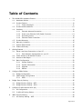
Table of Contents
1.
The WLAN ODU Hardware Feature............................................................................. 9
1.1
Hardware Outline ........................................................................................... 9
1.2
Product Feature ............................................................................................10
1.2.1
2.
1.3
Product and Accessories.................................................................................12
1.4
Interface .....................................................................................................12
1.4.1
External Antenna Connection...............................................................12
1.4.2
Power over Ethernet (PoE) Cable Connector...........................................13
1.4.3
Grounding Screw ...............................................................................14
1.4.4
Ethernet Cable Connection ..................................................................15
1.5
Product Warranty ..........................................................................................15
1.6
Warranty Limitation .......................................................................................15
1.7
System Requirement .....................................................................................16
1.8
Feature Summary .........................................................................................16
Getting Started .....................................................................................................17
2.1
Setup Local Area Connection on Your PC...........................................................17
2.1.1
3.
5.
6.
Start Network Configuration on your PC ................................................17
2.2
Check Access to WLAN ODU Product ................................................................20
2.3
Access to Web Pages .....................................................................................21
2.4
Basic Configuration .......................................................................................22
2.4.1
System Setting..................................................................................22
2.4.2
System Information ...........................................................................25
2.4.3
Upgrade ...........................................................................................27
2.4.4
Reboot .............................................................................................29
Configure 5GHz Bridge ...........................................................................................30
3.1
Bridge Configuration......................................................................................30
3.2
5GHz Bridge Joining Status ............................................................................34
3.2.1
4.
Feature Highlight ...............................................................................11
RSSI ................................................................................................34
Bridge Security Setting...........................................................................................36
4.1
Bridge Security Setting - WEP .........................................................................37
4.2
Bridge Security Setting – WPA ........................................................................39
Configure 2.4GHz Access Point (AP) .........................................................................41
5.1
AP Configuration ...........................................................................................41
5.2
2.4GHz AP Joining Status ...............................................................................44
4BAP Security Setting ............................................................................................45
6.1
AP Security Setting - WEP ..............................................................................46
Page 5 of 49
6.2
AP Security Setting – WPA..............................................................................47
6.2.1
Enterprise / Radius support .................................................................48
Page 6 of 49
Table of Figures
Figure 1
WLAN ODU Hardware Outlook ........................................................................... 9
Figure 2
WLAN ODU antenna connection........................................................................12
Figure 3
PoE Connector Interface..................................................................................13
Figure 4
Ethernet Cable Connection to Host PC ...............................................................15
Figure 5
Ethernet Cable Connect to WLAN ODU ..............................................................15
Figure 6
Windows Start Menu.......................................................................................17
Figure 7
Network Connection .......................................................................................18
Figure 8
Local Area Connection Properties......................................................................18
Figure 9
Internet Protocol Properties .............................................................................19
Figure 10
PING & ARP Command ..................................................................................20
Figure 11
User Name and Password Web Page ................................................................21
Figure 12
System Setting Page.....................................................................................22
Figure 13
System Information Page ..............................................................................25
Figure 14
Upgrade Page ..............................................................................................27
Figure 15
Rebooting Page ............................................................................................29
Figure 16
5GHz Radio Basic Setting Page .......................................................................30
Figure 17
Master/Slave Bridges Connections ..................................................................34
Figure 18
RSSI Page ...................................................................................................35
Figure 19
Bridge Security-WEP Page .............................................................................37
Figure 20
Bridge Security-WPA Page .............................................................................39
Figure 21
2.4GHz Radio Basic Setting Page ....................................................................41
Figure 22
QoS parameters ...........................................................................................43
Figure 23
Associated client Connections.........................................................................44
Figure 24
AP Security-WEP Page...................................................................................46
Figure 25
AP Security-WPA Page...................................................................................47
Figure 26
Radius configuration Page..............................................................................48
Page 7 of 49
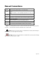
Manual Conventions
Bold
Italic
Courier
Bold type within paragraph text indicates commands, files names,
directory names, paths, output, or returned values.
Within commands, italics indicate a variable that the user must
specify.
Titles of manuals or other published documents are also set in
italics.
The courier font indicates output or display.
|
Within commands, items enclosed in square brackets are optional
parameters or values that the user can choose to specify or omit.
Within commands, item enclosed in braces are options from which
the user must choose.
Within commands, the vertical bar separates options.
…
An ellipsis indicates a repetition of preceding parameter.
>
The right angle bracket separates successive menu selection.
[]
{}
NOTE: This message denotes neutral or positive information that calls out important points
to the text.
A note provides information that applies only in special cases.
Caution: Cautions call special attention to hazards that can cause system damage or
data corruption, to a lesser degree than warnings.
Warnings: Warnings call special attention to hazards that can cause system damage,
data corruption, personal injury, or death.
Page 8 of 49
1. The WLAN ODU Hardware Feature
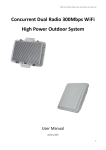
1.1 Hardware Outline
Figure 1 WLAN ODU Hardware Outlook
Page 9 of 49
1.2 Product Feature
Range — the WLAN ODU wireless bridge has been refined and optimized for long
range application, up to 35Km.
Temperature — the WLAN ODU wireless AP/bridge is tested for normal operation in
the ambient temperatures from -40°C to 60°C.
Operating in temperatures outside of
this range may cause the unit to fail.
Wind Velocity — the WLAN ODU wireless AP/bridge can operate in winds up to 90
MPH and survive higher wind speeds up to 125 mph. You must consider the known
maximum wind velocity and direction at the site and be sure that any supporting
structure, such as a pole, mast, or tower, built to withstand this force.
Lightning — the WLAN ODU wireless bridge includes its own built-in lightning
protection. However, you should make sure that the unit, any supporting structure,
and cables are all properly grounded.
Additional protection using lightning rods,
lightning arrestors, or surge suppressors may also employed.
Rain — the weather plays one of major matters to the antenna performance for the
wireless communication.
The raining day, the lightning day, the cloudy day, or the
windy day will make a quite big impact to the both side antennas over the
communication results.
It will also cause the communication quality.
The WLAN ODU
wireless bridge is weatherproofed outdoor unit, which can operate in extremely
weather environment.
You may need to use the sealing tape around the external
antenna port connectors for extra protection.
If moisture enters the connector, it
may cause degradation in performance or even a complete failure of the link.
Page 10 of 49
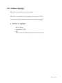
1.2.1 Feature Highlight
5GHz 802.11a/n based Point-to-Point Bridge
5GHz 802.11a/n based Point-to-Multipoint Bridge (up to 8 links)
2.4GHz 802.11b/g/n based high capacity access point coverage
z
Release 3.1 highlight
SNMP support
Management VLAN
NTP
802.1x Enterprise RADIUS support per WPA encryption
Page 11 of 49
1.3 Product and Accessories
The WLAN ODU
AC/DC PoE Injector
RJ-45 Installation kits
Mounting Kit
1.4 Interface
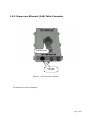
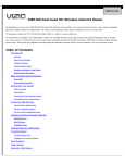
1.4.1 External Antenna Connection
External
Antenna
Connector for
5GHz 802.11an
Antenna #1
External Antenna
Connector for
5GHz 802.11a/n
Antenna #2
Figure 2
WLAN ODU antenna connection
Page 12 of 49
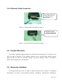
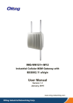
1.4.2 Power over Ethernet (PoE) Cable Connector
Grounding Screw
PoE Cable
Connector
Figure 3
PoE Connector Interface
The antenna connection diagram :
Page 13 of 49
1.4.3 Grounding Screw
1) For grounding strip connection.
2) Proper grounding is always for the safety consideration.
Page 14 of 49
1.4.4 Ethernet Cable Connection
Ethernet cable connects to
Input port and link to host
PC or LAN Device (ex.
Switch or Hub)
Figure 4
Ethernet Cable Connection to Host PC
PoE Ethernet Cable
connects to Output port
and link to WLAN ODU
Figure 5
Ethernet Cable Connect to WLAN ODU
1.5 Product Warranty
This product warranted against defects in materials and workmanship for a period of one
year from date of shipment. If the customer wants to have or extend longer warranty period,
please contact the sales for extended warranty. During the warranty period, the defective
product will be repaired or to be replaced.
1.6 Warranty Limitation
The foregoing warranty shall not apply to defects resulting from improper or inadequate
maintenance by buyers, buyer-supplied software, interfacing, unauthorized modification,
Page 15 of 49
inappropriately use, operation out of the product environment specifications, or improper site
preparation and maintenance.
1.7 System Requirement
Windows 2000, XP, Vista or Windows 7
Microsoft Internet Explorer 5.5 or above versions
One RJ-45 Ethernet network cable & PoE injector module
1.8 Feature Summary
Provide the Ethernet to Wireless LAN Bridge, or the Ethernet to Wireless LAN Access
Point, fully IEEE 802.3 compatible Ethernet interface
Support 10/100 Base-T Ethernet interface
The operating mode is IEEE 802.11a/n & 802.11b/g/n infrastructure for WLAN ODU
The dynamic data rate switching among standard 802.11a, 802.11b, 802.11g,
802.11n-HT20, 802.11n-HT40 provided by Atheros chipset. The featured auto fallback
data rate capability optimizes the reliability, throughput and transmission range.
Using the TFTP or Web UI to upgrade the firmware.
Built-in lightning protection circuit.
Outdoor environment comply with IP67
Page 16 of 49
2. Getting Started
2.1 Setup Local Area Connection on Your PC
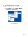
2.1.1 Start Network Configuration on your PC
1) Click the “Start Menu” and choose “All Programs” -> "Accessories" ->
"Communications" -> "Network Connections".
Figure 6
Windows Start Menu
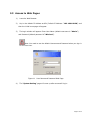
2) Right-click on the “Local Area Connection” and select “Properties”.
Page 17 of 49
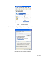
Figure 7
Network Connection
3) After clicking on “Properties”, you will see the diagram as below.
Figure 8 Local Area Connection Properties
Page 18 of 49
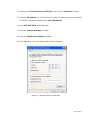
4) Marking the “Internet Protocol (TCP/IP)” and click the “Properties” button.
5) Input an “IP address (ex. 192.168.100.2)” under the same subnet as the Default
IP Address of Outdoor WLAN Product (192.168.100.20).
6) Input 255.255.255.0 as Subnet Mask.
7) Keep the “Default Gateway” as blank.
8) Keep the “DNS Server Address” as blank.
9) Click ”OK” when you finish setting and Close the Window.
Figure 9
Internet Protocol Properties
Page 19 of 49
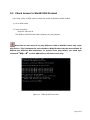
2.2 Check Access to WLAN ODU Product
Use “Ping” utility of DOS mode to check the access to Outdoor WLAN Product.
1) Go to DOS mode
2) Type command:
ping 192.168.100.20
The Outdoor WLAN Product shall respond your ping request.
Note that use the same PC to ping different Outdoor WLAN Product may cause
ping failure. This is because the entire Outdoor WLAN Product has the same default IP
address but different MAC addresses. To prevent from ping failure, you need type
command
“arp –d”
to clear ARP table on PC before each ping.
Figure 10 PING & ARP Command
Page 20 of 49
2.3 Access to Web Pages
1)
Launch a Web Browser.
2)
Key in the default IP Address as URL (Default IP Address: “192.168.100.20’) and
then the initial home page will appear.
3)
The login window will appear. Enter User Name (default username is ”Admin”)
and Password (default password is” Wireless”).
Note: You need to use the default Username and Password when you sign in
for the first time.
Figure 11
4)
User Name and Password Web Page
The “System Setting” page will come up after successful log in.
Page 21 of 49
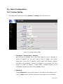
2.4 Basic Configuration
2.4.1 System Setting
This page can be access by clicking “System -> Setting” from left side menu.
Figure 12 System Setting Page
1) IP Address / Subnet Mask / Gateway
Note that each AP/Bridge unit in the same network must be assigned an
unique IP address. So, you may need to have a network plan before
deployment. Enter the IP address, Subnet Mask and Gateway Address
according to the planning. If there is no gateway in the network, you may
leave it in blank. IP Address / Subnet Mask / Gateway change will be
immediately applied right after clicking “Save” button.
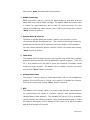
2) Password
Change Password by typing new password, and confirm new password, and
clicking “Save” button. User will be asked to login again use new password
Page 22 of 49
after reboot. Note: the password is case sensitive
3) SNMP Community
SNMP Community name is a string for administrator to read and write the
SNMP MIB from external SNMP manager. The default SNMP community name
is “public” for read community, and “private” for write community. You may
change the community name as your plan. Confirm your setup then clicking
“Save” button to perform.
4) System Name & Location
The fields of System Name and System Location is the strings for you to
conveniently identify the different unit. The content of the string is empty by
default and can be any ASCII characters with max. length of 255 characters
for both System Name and System Location. Confirm your setup then clicking
“Save” button to perform.
5) ICMP Echo
The Outdoor WLAN Product normally may respond ping (ICMP Echo) request.
However, the ping response may be disabled for special purposes. Thus, the
PC in this network won't be able to probe the existence of Outdoor WLAN
Product by ping command. The default value is "Enable". Confirm your setup
then clicking “Save” button to perform.
6) Management VLAN
The system is able to specify a VLAN identification (ID) for all management
packets. The VLAN ID can be 2-4094. And, specify 0 to disable this function.
Confirm your setup then clicking “Save” button to perform.
7) NTP
The Network Time Protocol (NTP) is a protocol and software implementation
for synchronizing the clocks of computer systems over packet-switched,
variable-latency data networks. The available NTP server IP & its availability
can be found by the following hyperlink (http://www.pool.ntp.org/en/). Enable
this feature and specific the IP address of NTP server IP to get the system
date & time through NTP protocol.
Page 23 of 49
Time zone: specify the time zone that the product located.
This setting is
based on the GMT (Greenwich Mean Time).
Daylight Saving Time: Many countries, and sometimes just certain regions of
countries, adopt daylight saving time (DST) during part of the year.
It needs
to enable or disable based on the product located countries or area.
Confirm your setup then clicking “Save” button to perform.
8) Reset to Factory Default button
Click this button to set all the parameters back to factory default value
by “Reset All” button, or all the parameters back to factory default
value but keep the existing IP setting by “Reset All, but keep IP
Settings” button. This command only set the configuration parameters to
the factory default value, and the software version would be keep in the
current activate version.
Warning: The IP Address and Password will be reset if “Reset All”
button selected after reboot.
Please use the default value for next login.
9) click “Reboot” button when you finish setting up for parameter changes
taking effect.
Page 24 of 49
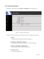
2.4.2 System Information
This page can be access by clicking “System -> Information” from left side menu
Figure 13
System Information Page
This page lists the important system information and software / hardware inventory data.
1) Uptime
The elapse time since Outdoor WLAN Product had been up.
2) IP address / Subnet Mask / Gateway
The IP address / Subnet Mask / Gateway of the wireless ODU setting.
3) Ethernet / 5G RF MAC / 2.4GHz RF MAC
The MAC address of Ethernet and wireless interface.
4) Firmware version
The running firmware version.
Page 25 of 49
5) Traffic Info
The statistic data for the packets transmitted by Ethernet and the wireless
interfaces.
Page 26 of 49
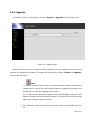
2.4.3 Upgrade
The reboot function can be apply by clicking “System -> Upgrade” from left side menu
Figure 14 Upgrade Page
When the new version of firmware has been received, you can upload the file by the web
interface for upgrade the firmware. The page can be access by clicking ”System -> Upgrade”
from the left side menu.
Note:
(a). Before upload the new version of firmware, please read the new firmware
release note to confirm the new firmware features, upgrade environment, and
procedures can meet the upgrade requirements.
(b). in case network disruption happens during file uploading, system will still
keep on running with current active firmware. You may perform the file upload
again when network is back to normal.
1) Click “Browse” button and select the firmware files to be uploaded from the
PC.
Page 27 of 49
2) Click “Upload”.
3) When uploading is completed, system will prompt the successful message!
Then reboot to perform the new version of firmware.
4) Click “Reboot” for new firmware to take effect.
Page 28 of 49
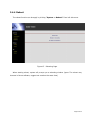
2.4.4 Reboot
The reboot function can be apply by clicking “System -> Reboot!” from left side menu
Figure 15 Rebooting Page
When starting reboot, system will prompt you a rebooting window. (bpan: The reboot may
increase in future software, suggest not mention the exact time)
Page 29 of 49
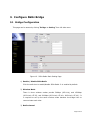
3. Configure 5GHz Bridge
3.1 Bridge Configuration
This page can be access by clicking “Bridge -> Setting” from left side menu
Figure 16
5GHz Radio Basic Setting Page
1) Enable / Disable 5GHz Radio
Click the radio box to enable/disable 5GHz Radio. It is enabled by default.
2) Wireless Mode
There is three wireless modes provide 54Mbps (802.11a), and 150Mbps
(802.11a/n HT-20), and 300Mbps (802.11a/n HT-40+, 802.11a/n HT-40-). It
is required to set up the same wireless mode between the bridge links to
communicate each other.
3) Radio channel
Page 30 of 49
Select a radio channel according to the availability or system plan. It is
required for Bridges having the same radio frequency to communicate each
other.
4) Data Rate
Available data rate range is dependent upon the selection of Wireless Mode
setting. Rates of 6, 9, 12, 18, 24, 36, 48 and 54Mbps are supported for the
wireless mode of 54Mbps (802.11a). And, rates of MCS-0, MCS-1, MCS-2,
MCS-3, MCS-4, MCS-5, MCS-6, MCS-7, MCS-8, MCS-9, MCS-10, MCS-11,
MCS-12, MCS-13, MCS-14, and MCS-15 are supported for the wireless mode
of 802.11a/n HT-20, 802.11a/n HT-40+, and 802.11a/n HT-40-. The default
data rate is “Auto”. It is recommended to keep the default data rate
for bridge mode.
5) Bridge Mode
Select "Master" for Master Bridge mode. or, select “Slave” for Slave Bridge
mode.
Note: When “Master Bridge Mode” is enabled, the remote bridge mode shall
be in “Slave Bridge Mode”.
One bridge network shall have one WLAN ODU in
“Master Bridge Mode”, and the others shall be in “Slave Bridge Mode”.
6) Remote Bridge Setup
In order to establish the wireless link between Bridge Radios, the MAC address
of remote Bridge(s) needs to be register in address table. Type the MAC
address with format like xx:xx:xx:xx:xx:xx (x is the hexadecimal digit),
Master Bridge Radio may accommodate up to 8 remote MAC addresses by the
current software support. In addition, Slave Bridge Radio supports only 1 MAC
address which have to be Master Bridge.
7) Security
Please refer to Chapter 4 for security setting.
4X
8) Bridge Distance
Page 31 of 49
Setup “Bridge Distance” according to the longest link distance between the
Master and Slaves in the network. The input needs to be greater than or equal
to the real distance. The range can be from 1KM to 35KM. In Master Bridge
mode, the maximum distance information of the bridge links needs to be fit.
9) RTS Threshold
In order to prevent the transmission collision in a hidden nodes environment,
Bridge may send a RTS (Request To Send) before transmitting the data frame
and expect to receive a CTS (Clear To Send) from remote Bridge. You may
define a threshold for those frame size greater than the threshold need to
activate RTS/CTS mechanism. The valid range is between 256 and 2347. Set
low value to this threshold may avoid collision, but the RTS/CTS frame would
consume bandwidth. The default RTS threshold value is “2347”.
Note: In Point to Multi-Point application, the transmission collision
may be caused by hidden nodes affection in particular environment or
network configuration. Setting smaller number of RTS threshold could
alleviate the hidden nodes problem.
10) Tx Power
Available selection of Transmit Power are Full, Half (-3dB), Quarter (-6dB),
and Eighth (-9dB). Select the appropriate Transmit Power according to the
distance and environmental factor between Bridges.
The default setting is
“Full”.
11) Auto Reboot
Default is “Disable”, when “auto-reboot” feature is enabled, if near-end AP
cannot receive “alive message” from far-end AP in a certain period. Then,
“auto-reboot” will be automatic performed at near-end AP without notice. The
“alive message” is communicated between near-end & far-end AP via 5GHz
bridge links.
12) Click “Save” and then “Reboot” button when you finish setting up for
parameter changes taking effect.
Page 32 of 49
Page 33 of 49
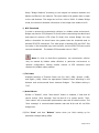
3.2 5GHz Bridge Joining Status
This page shows the local and remote Bridges and can be access by clicking “Bridge ->
Status” from left side menu.
Figure 17 Master/Slave Bridges Connections
1) Remote Bridge
This line shows the MAC address, IP address and RSSI of remote Bridge.
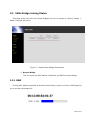
3.2.1 RSSI
Clicking MAC address hyperlink of desired remote Bridge, system will show a RSSI page for
you to monitor the bridge link.
Page 34 of 49
Figure 18
RSSI Page
RSSI values on this page is automatically refreshed every second to reflect the real-time
receiving signal strength.
Page 35 of 49
4. Bridge Security Setting
To have a secured data transmission, Outdoor WLAN Product provides the following
encryption types.
No Security as the default setting
64-bit & 128-bit & 152-bit WEP
WPA-TKIP or WPA-AES
Note that it is required to have the same security setting between Bridges to
communicate.
Page 36 of 49
4.1 Bridge Security Setting - WEP
This page can be access by clicking “Bridge -> Setting” page.
Figure 19 Bridge Security-WEP Page
1) Security Mode
select “WEP” to enable the security mode.
2) Encryption Key
The WEP key is an ASCII string, can be in one of the following formats: 5
characters, 13 characters, or 16 characters.
Note that it is required to have the same security setting between
Bridges to communicate.
3) Click “Save” and then “Reboot” button when you finish setting up for
parameter changes taking effect.
Page 37 of 49
Page 38 of 49
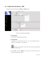
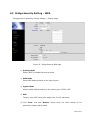
4.2 Bridge Security Setting – WPA
This page can be access by clicking “Bridge -> Setting” page.
Figure 20 Bridge Security-WPA Page
1) Security Mode
Select “WPA” to enable the security mode.
2) WPA Mode
Select WPA Mode according to the security plan.
3) Cypher Mode
Select Cypher Mode according to the security plan. TKIP or AES
4) PSK
The key is an ASCII string with length from 8 to 63 characters.
5) Click “Save” and then “Reboot” button when you finish setting up for
parameter changes taking effect.
Page 39 of 49
Note that it is required to have the same security setting between
Bridges to communicate.
Page 40 of 49
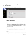
5. Configure 2.4GHz Access Point (AP)
5.1 AP Configuration
This page can be access by clicking “AP -> Setting” from left side menu
Figure 21 2.4GHz Radio Basic Setting Page
1) Enable / Disable 5GHz Radio
Click the radio box to enable/disable 2.4GHz Radio. It is enabled by default.
2) Wireless Mode
There is three wireless modes provide: 54Mbps (802.11g), and 150Mbps
(802.11g/n HT-20), and 300Mbps (802.11g/n HT-40+, and 802.11g/n HT-40-).
It is required to set up the same wireless mode between the AP links to
communicate each other.
3) Radio channel
Select a radio channel according to the availability or system plan. It is
required for AP having the same radio frequency to communicate each other.
4) SSID
SSID is used to broadcast the AP service, the client can associate the AP by
the specific SSID.
The valid length shall not exceed 32 alphanumeric
Page 41 of 49
characters and case-sensitive.
All SSID would broadcast its own beacon.
The default SSID is “AP_2G”.
5) Suppress SSID
When you enable “Suppress SSID” function, SSID information will be removed
from AP broadcast frame. Thus, only those stations aware of the SSID can
associate with AP. The default setting is disabled.
6) Security
By default, the security is disabled. Please refer to Chapter 6 for security
4X
setting to configure the security features such as WEP, WPA-TKIP, WPA-AES,
WPA2-TKIP and WPA2-AES.
7) RTS Threshold
In order to prevent the transmission collision in a hidden nodes environment,
AP may send a RTS (Request To Send) before transmitting the data frame and
expect to receive a CTS (Clear To Send) from the client. the threshold for
those frame size greater than the threshold needs to activate RTS/CTS
mechanism. The valid range is between 256 and 2347. Set low value to this
threshold may avoid collision, but the RTS/CTS frame would consume
bandwidth. The default RTS threshold value is “2347”.
8) Tx Power
Available selection of Transmit Power are Full, Half (-3dB), Quarter (-6dB),
and Eighth (-9dB). Select the appropriate Transmit Power according to the
distance and environmental factor between Bridges.
The default setting is
“Full”.
9) WMM
Multimedia applications in a WiFi network require Quality of Service (QoS)
functionality.
The system default enabled WMM QoS feature, and it will
prioritize traffic and optimizes the way shared network resources among
different applications. It works well for data traffic from applications such as
web browser, file transfer, or email, but it is inadequate for multimedia
applications.
Voice over Internet Protocol (VoIP), video streaming, and
interactive gaming are highly sensitive to latency increases and throughput
Page 42 of 49
reductions, and required to enable QoS feature.
The QoS parameters is
default according to IEEE 802.11e as Figure 22.
Figure 22 QoS parameters
Note:
- AC_BE: Best effort packet
- AC_BK: Background packet
- AC_VI: Video packet
- AC_VO: Voice packet
10) Click “Save” and then “Reboot” button when you finish setting up for
parameter changes taking effect.
Page 43 of 49
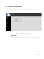
5.2 2.4GHz AP Joining Status
This page shows the associated client and can be access by clicking “AP -> Status” from left
side menu.
Figure 23 Associated client Connections
1) Client status
This line shows the MAC address of associated client as well as its RSSI value
Page 44 of 49
6. AP Security Setting
4B
To have a secured data transmission, Outdoor WLAN Product provides the following
encryption types.
No Security as the default setting
64-bit & 128-bit & 152-bit WEP
WPA
Page 45 of 49
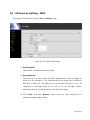
6.1 AP Security Setting - WEP
This page can be access by clicking “AP -> Setting” page.
Figure 24 AP Security-WEP Page
1) Security Mode
select “WEP” to enable the security mode.
2) Encryption Key
There are up to 4 keys can be specified. Administrator needs to assign an
active key for encryption.
The supported WEP key length can be WEP-64,
WEP-128, or WEP-152. The WEP key can be an ASCII string of 5, 13, or 16
characters; or HEX digit string (0-9 or A-F) of 10, 26, 32 digits. System
determines the key format according to the input key length.
3) Click “Save” and then “Reboot” button when you finish setting up for
parameter changes taking effect.
Page 46 of 49
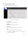
6.2 AP Security Setting – WPA
This page can be access by clicking “AP -> Setting” page.
Figure 25 AP Security-WPA Page
1) Security Mode
Select “WPA” to enable the security mode.
2) WPA Mode
Select WPA Mode according to the security plan.
3) Cypher Mode
Select Cypher Mode according to the security plan: TKIP or AES.
4) PSK
The key is an ASCII string with length from 8 to 63 characters.
5) Click “Save” and then “Reboot” button when you finish setting up for
parameter changes taking effect.
Page 47 of 49
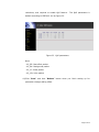
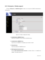
6.2.1 Enterprise / Radius support
Clicking ”Enterprise / RADIUS support” radio box to setup the RADIUS authentication
configuration.
Figure 26
Radius configuration Page
1) Authentication RADIUS Server
Input the IP address or server name of RADIUS server.
2) Authentication RADIUS Port
Input the port of RADIUS. The default port number is 1812.
3) Shared Secret
Input the password of RADIUS server.
4) EAP Reauthentication Period
Specify EAP Reauthentication Period in seconds. Enter 0 to disable the
update. The default value is 0.
Page 48 of 49
5) Click “Save” and then “Reboot” button when you finish setting up for
parameter changes taking effect.
Page 49 of 49