1
FIRE AND ALARM CONSOLE
S2000M
Maintenance guide
FIRE AND ALARM CONSOLE
TABLE OF CONTENTS
1 Description of the product and its operability
1.1 Purpose
1.2 Specifications
1.3 Delivery set
1.4 Description the product and capabilities
2 Maintenance
2.1 Preparation the product
2.1.1 General information
2.1.2 Connection console and devices to RS-485 interface instructions
2.1.3 Setting device configuration parameters
2.1.4 Address setting of addressable expanders
2.1.5 Printer connection to console or ‘ARM S2000’
2.1.6 Using the console for “ARM Orion” redundancy
2.1.7 Console configuring
2.1.7.1 General information
2.1.7.2 Adding devices into console database and partition creation
2.1.7.3 Setting partition control rights and password programming
2.1.7.4 Setting control by system relay outputs
2.1.7.5 Setting message transmission
2.1.7.6 Entry zone settings
2.1.7.7 Setting user messages
2.1.7.8 Controlling ‘S2000-BI’ devices settings
2.1.7.9 Using the console for creating of systems controlling gas, powder or aerosol fire
extinguishing installations based on "S2000-ASPT" devices
2.1.7.10 Using the console with sprinkler or drencher extinguishing units based on devices
"POTOK-3N"
2.1.7.11 Using the console with the phone communicator "S2000-IT"
2.1.8 Console mounting
2.1.9 Prevention of the accidents at device installation
2.1.10 Console first starting
2.2 Using console
2.2.1 Displaying, viewing and printing device messages
2.2.2 Partition arming and disarming
2.2.2.1 Console controlling of partitions
2.2.2.2 Partition control at ‘S2000-K’ keyboards
2.2.2.3 Touch Memory and Proximity card partition control
2.2.3 Device control functions
2.2.3.1 Arming/disarming control of device alarm loops
2.2.3.2 Device alarm reseting
2.2.3.3 Manual external device outputs control
2.2.3.4 ‘S2000-ASPT’ device control
2
4
4
5
14
14
15
15
15
16
18
19
19
20
25
25
26
27
29
30
31
31
31
32
33
33
34
34
34
34
35
37
37
39
39
39
39
41
41
42
S2000M
2.2.3.5 Request for loop state
2.2.3.6 Alarm loop resistance measurement
2.2.3.7 Console date and time setting
2.2.3.8 Printing event buffer
2.2.3.9 ‘S2000-IT’ phone communicator message buffer cleaning
2.2.3.10 Alarm message indication reset
2.2.4 Device and console programming functions
2.2.4.1 Date and time settings and clock correction
2.2.4.2 RS-485 device address changing
2.2.4.3 2-wire devices adresses changing and programming
2.2.4.4 Console extra settings
2.2.4.5 Password management
2.2.4.6 Console address setting in prorgamming mode
2.2.4.7 Console address setting in personal computer work mode
2.2.4.8 Console RS-232 interface operative mode settings
2.2.4.9 The ring RS-485 interface operative mode settings
2.2.4.10 Console entering into programming mode
2.2.5 Reset settings to default values
2.2.6 Console version update
3 STORAGE
4 TRANSPORTATION
5 CERTIFICATION INFORMATION
6 INFORMATION ABOUT MANUFACTURER
7 WARRANTY
Appendix A
‘S2000M’ console dimensions
Appendix B
Zone status list
Appendix С
The list of messages being displayed
MAINTENANCE GUIDE
43
43
44
45
45
45
46
46
47
47
48
49
51
51
51
52
53
53
54
54
54
54
54
55
56
57
61
3
FIRE AND ALARM CONSOLE
This maintenance guide is intended to help you to study the operation and maintenance
principles of Fire and Alarm Console ‘S2000M’ version 2.04 (elsewhere the console). Console
version is shown on the label on the processor, which can be seen when console back cover is
open.
1
Description of the product and its operability
1.1 Purpose
1.1.1 ‘S2000M’ fire and alarm console is designed to work as part of fire-alarm system.
It checks device states and gathers information, logs system events, indicates alarms, controls
arm, controls disarm, controls by automatics. Console joins connected to it devices in one
system, providing interaction between each other. It is necessary for using ‘Signal-20P’, ‘S2000KDL’, ‘S2000-SP1’, ‘S2000-BI’, ‘S2000-K’, ‘S2000-IT’ devices.
1.1.2 Console can be connected to receive-checking devices ‘Signal-20’, ‘Signal-20’
version 02, ‘Signal-20P’, ‘S2000-4’, 2-wired line ‘S2000-KDL’ controllers, keyboards
‘S2000-K’ and ‘S2000-KC’, relay’s ‘S2000-SP1’ modules, ‘S2000-BI’ indication blocks,
‘S2000-IT’ phone informators, ‘S2000-ASPT’ extinguish control devices, checking-start
‘S2000-KPB’ units, ‘S2000-2’ access control devices. Devices and console are jointed in the
system through RS-485 interface. In the system console plays role of central controller, which
gathers information from connected devices and controls by arm/disarm alarm loops of devices
and by system outputs (relay outputs or ‘open collector’ outputs). One can be only one console
‘S2000M’ in the system! Receive-checking devices ‘Signal-20’, ‘Signal-20’ version 02,
‘Signal-20P’, ‘S2000-4’ analyze the state of the alarm loop, control by their outputs, transmit to
the console through RS-485 interface information about state of alarm loop and allow
arm/disarm alarm loop by console commands through RS-485 interface. Controller
‘S2000-KDL’ analyzes the state of addressable detectors and connected via 2-wire addressable
communication line expanders, transmits the status information to the console and allows to
arm/disarm them by console command. Keyboard ‘S2000-K’ is design for additional partition
control points and word under console control. It also allows displaying transmitted by keyboard
messages on the liquid-crystal indicator with alarm message sound indication. LED ‘S2000-KS’
keyboard is also designed for additional control points. It can show up to 20 partitions on the
LED indicators. Signal-start ‘S2000-SP1’ unit allow the console controlling by their relay
outputs through RS-485 interface and is design to contact system relay outputs. ‘S2000-BI’
indication block is design for indication at built-in LED indicators and sound indicator states of
system partitions. ‘S2000-IT’ phone phone communicator is design to transmit console messages
through phone lines in form of voice or pager messages, and also ADEMCO ID Contact format
messages.
1.1.3 Console displays at liquid crystal display (LCD) messages about fires, alarms,
faults, arm, disarm and other system events. There is the opportunity of sound alarm message
signaling. Console can log device messages on printer with с sequential RS-232 interface (for
example, EPSON LX-300, LX-300+). Console keeps messages in nonvolatile event buffer. Its
content can be viewed on LCD. Console may print buffer content on the printer. Console may
transmit messages to the ‘S2000-K’ keyboards for displaying and to the phone informators for
transmission through phone.
1.1.4 Console has set of standard messages, displayed on LED indicators and printed, and
also allows set non standard alarm loop message displaying.
Console allows one to control by arm/disarm of any alarm loop of connected devices, and
also check alarm loop states. Access to the functions is password protected.
4
S2000M
MAINTENANCE GUIDE
1.1.5 Console may logically group alarm loops in partitions. Partition is a set of alarm
loop that is controlled as one unit. This gives next advantages:
− Arm/disarm require fewer users actions take less time, and probability of operators
mistake is decreased also. If need to arm the large number of ALs, especially if there are ALs of
different devices, joining the alarm loop give very significant event;
− User can arm/disarm just partitions, authorized to him;
− Partition arm/disarm can be controlled not only at console, but also at connected
‘S2000-K’ and ‘S2000-4’ devices;
− New opportunity to organize the system outputs (relay’s) is added;
− ‘S2000-BI’ units can be used for partitions state indication.
There are the restrictions:
− Number of alarm loop, that can be included in partitions, is limited;
− Console has to be configured with help of personal computer.
1.1.6 Console allows group partitions in the groups. Partitions group can be controlled
(Arm/disarm), and also display their states on indication ‘S2000-BI’ blocks and LED ‘S2000KS’ keyboards.
1.1.7 Console allows one to control by partition arm/disarm and to view their states.
Access to the functions is password protected (PIN-code, Touch Memory key or Proximity card).
Partitions that authorized to user, and partition control rights (arm/disarm permission), are
determined by level of its password. Console indicates arm/disarm operation result. Partition
control possible both at console (PIN-code), and at connected to console ‘S2000-K’ keyboards
(PIN-code) and devices’S2000-4’ (Touch Memory key or Proximity card).
1.1.8 Console may use ‘S2000-BI’ devices for partitions state indication.
1.1.9 Console synchronizes time and date in devices. It is necessary for normal time
window operability in ‘S2000-4’ and ‘S2000-2’ devices. Console provides connection between
‘S2000-2’ device. It is necessary for normal operability network Anti pass back mode (second
passing prohibition) in access control system on the basis of ‘S2000-2’ devices.
1.1.10 Console controls by ‘S2000-SP1’ device relay outputs. These output we will call
system outputs (in opposite to the alarm panel local outputs, controlled by devices itself). System
output reaction depends on state of connected partitions and control program. System relay
outputs can be used for control by light and sound notificators, operational device switching, alarm
message transmitting to the CGP. Except ‘S2000-SP1’ device outputs ‘S2000-KPB’, ‘S2000-4’,
‘Signal-20P’ and ‘Signal-20’ series 02 device outputs can be used as system outputs.
1.1.11 Console allows changing connected through RS-485 interface device addresses,
and also programming and changing address expanders addresses ‘S2000-AP1’, ‘ S2000-AP2’
and address notificators ‘IPR 513-3A’, ‘S2000-SMK’, ‘DIP-34A ver.01’, ‘S2000-IP ver.01’,
connected to the ‘S2000-KDL’ controller two wired connection line. Programming functions are
protected by password.
1.1.12 Console figured for 24-hour work.
1.1.13 Console must be protected from action of atmospheric condensations and
mechanical damage.
1.1.14 Temperature range for console is from 274 to 313 К (from +1 to +40 ОС).
1.2 Specifications
1.2.1 Voltage of direct current power supply of the console is from 10,2 to 28,4 V.
1.2.2 Consumed current in standby mode is: if supply voltage 12 V - 70 mA, if supply
voltage is 24 V - 35 mA.
1.2.3 Liquid crystal two line indicator, 16 symbols in the line, with green highlight.
5
FIRE AND ALARM CONSOLE
1.2.4 Length of the RS-485 communication line is no more then 4000 m.
1.2.5 Length of the RS-232 communication line is no more then 20 m.
1.2.6 Values of created by console radio noise are fewer standards.
1.2.7 Console is stable to the electromagnetic noise.
1.2.8 Average work time is below 20000 hr that correspond the probability of nonbreak work 0,95 per 1000 hr.
1.2.9 Average console life time is 10 years.
1.2.10 Mass - no more then 0,3 kg.
1.2.11 Dimensions - 140×114×25 mm.
1.2.12 Console’s construction satisfies fire rules in the case of malfunction and in the
case of violate of maintenance rules.
1.2.13 Number of connected to console through RS-485 interface devices is no more
127.
1.2.14 Current system event console shows on the indicator, print and save in nonvolatile
buffer. Messages include event name (shown in appendix D), time (hour, minutes, seconds) and
data (day, month). They can also include information about message source (device address,
loop number, reader or relay), number and text partition description, number and user text
description. Event buffer keep up to 1023 last events. Buffer is ring, i.e. last message is saved
instead the oldest. Console can print bath all current messages, but also message categories.
There are following categories: ‘FIRES’, ‘ALARMS’, ‘FAULTS’, ‘ARM/DISARM’, ‘LOOP
ARM/DISARM’, ‘ACCESS’, ‘RELAY’, ‘SYSTEM INFO’, ‘AUXILIARY’. Full event list
presents (shown) in appendix D. Printer prints messages immediately at receiving. If console
worked some time without printer, then after printer connection saved in buffer events will be
printed automatically. Also there is a command for printing whole event buffer.
1.2.15 Console allows setting displaying and printing events from device alarm loops
and addres notificators. Obligatory condition – these loops should be saved in console database.
It has to be set message name, console message receiving sound signal, alarm level and has
message to the one of the categories. Message title is an arbitrary text line with length up to 16
symbols. Sound signal is settled by selection from list of standard signals. Alarm level
determines message displaying priority on the LED console at receiving different alarm
messages. Through message category one can set save the message in the console buffer, display
on the LED, print or transmits to the ‘S2000-K’ keyboards and ‘S2000-IT’ informators.
1.2.16 Console can translate system messages to the ‘S2000-K’ keyboards and ‘S2000IT’ informators. For any of the devices permitted message categories and partition list can be set.
1.2.17 Partition number in the system is 511. Partition group number is up to 128. The
number of alarm loops, that can be grouped in partitions are up to 2048. Alarm loops can be
included in partitions in arbitrary order, but any alarm loop can be included in one partition only.
Any partition can be included in any group, or in few groups, up to maximal number 128. For
each partition or partition group text description from 16 symbols can be set. This description
will be included in printing of the events and can be seen on the console LED.
1.2.18 Console has passwords system for access restriction to the arming/disarming and
programming functions. Password can has from 1 to 8 digits. Console allows set passwords for
2047 users. For each user text description (name) from 16 symbols can be set. Name or password
order number (from 1 to 2047) identify user in the system. User name is included in the event
printing and can be seen on console LED.
Password with order 1 is engineer password. It is unique password with the programming
function access. Engineer password owner can configure console and device parameters, setting
6
S2000M
MAINTENANCE GUIDE
addresses of devices and address expanders, set, change and remove user passwords, change own
password, setup and change console configuration for work with the partitions and relay outputs
at personal computer using program ‘pprog.exe’ ver. 2.04. This password has no device and
partition control rights! Engineer password can has from 1 up 8 digits. Default value is <123456>. Change it before starting device operation! Console allows reset the password in
default value if it was forgotten.
User passwords can have numbers from 2 to 2047 and designed for arming/disarming
control. PIN - codes, and Touch Memory keys and Proximity cards can be used as password. PIN
– code is digit code, input from the keyboard. Maximal PIN default length is 4 digits, but can be
changed in range from 1 to 8 digits. Touch Memory key and Proximity cards control is made by
readers, connected to the ‘S2000-4’, ‘S2000-2’, ‘Signal-20P SMD’ and ‘S2000-KDL’ devices.
Each user password has access level. According to level password can have partition
control rights or device control rights.
Access levels for partition control are determined accessible partitions and permitted for
control actions (partition arming/disarming). It can be set up to 252 access levels (numbers from 1 to
252). Partition control rights are described in the item.
Note – Access level can have control rights for any partition number (up to 511) and
partition groups (up to 128), but up to 8 access levels can have one partition or group.
Console has three default access levels for device control: ‘ARM and DISARM’, ‘ARM
w/o DISARM’, ‘MAX AUTHORITY’. Access level ‘ARM w/o DISARM’ gives the right for
alarm loop individual or group arming, and also alarm reset and alarm loop state request. Access
level ‘ARM and DISARM’ gives also the right for alarm loop individual or group arming and
disarming. Access level ‘MAX AUTHORITY’ has all control functions rights. Comparing with
the level ‘ARM and DISARM’ there are accessible general arming and disarming, manual
device output control, printing buffer events, setting time and data, request ADC. Device control
functions are described in item.
Note – Access to the control functions is protected by passwords, if option ‘CODE
REQUIRED’ is on. If option ‘CODE REQUIRED’ is off loop control functions are accessible
without password.
By default console has one user password, with number 2, it has value <1234> and access
level ‘MAX AUTHORITY’.
Console allows setup password owner to add, remove and change user passwords. Users
can change own password by console.
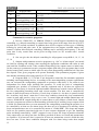
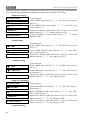
1.2.19 States of LED indicator ‘READY’ (green) in different modes of work through
interface RS-232 are shown in the table 1.
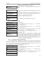
1.2.20 Console provides states indication of all system partitions on LED indicators
‘ALARM’, ‘FIRE’, ‘TROUBLE’ and ‘FAULT’ according to tables 2 - 5. Indicator’s colour is
red.
1.2.21 Console sound signals are shown in the table 6.
Mode
Work with printer
Work with computer
Programming mode,
Mode PI
Table 1 Indicator ‘READY’ (green)
State
Indication
Any
On
Norm
On
No connection with computer through RS-232
Blinks with frequency 1 Hz
Computer does not poll devices
Computer polls devices
Off
On, if computer sends data to the
device, else off
7
FIRE AND ALARM CONSOLE
State
Norm
SILENT ALARM
ALARM
INTRUSION ALARM
Table 2 Indicator ‘ALARM’ (red)
Indication
Off
Blink with frequency 2 HZ
Blink with frequency 1 HZ
Blink with frequency 4 HZ
State
Norm
FIRE
ATTENTION
Table 3 Indicator ‘FIRE’ (red)
Indication
Off
Blink with frequency 2 HZ
On for ¼ с frequency 1 HZ
State
Norm
NOT ARMING
LOOP OPEN CIRCUIT
LOOP SHORT CIRCUIT
CONFIGURATION ERROR
OPEN RELAY OUTPUT
RELAY OUTPUT SHORT CIRCUIT
BATTERY FAILED
AC POWER FAILED
POWER FAILED
State
Norm
DISCONNECTED ALARM LOOP
RELAY DISCONNECTED
2-WIRE LINE SHORT CIRCUIT
2-WIRE LINE TROUBLE
ENCLOSURE TAMPERING
Event or state
Norm
Button pressed
Successful operation
Unsuccessful operation
‘Intrusion alarm’ or
‘Silent alarm’ messages are received
‘Fire prealarm’ message is received
‘Fire alarm’ message is received
‘Tamper alarm’, ‘device restart’ messages are
received, disconnection the device is occurred
‘Loop trbl open’, ‘loop trbl short’, ‘fire trouble’,
‘2wire line open’, ‘2wire line short’, ‘2wire line
short’, ‘power failed’, ‘battery failed’, ‘AC power
failed’ messages are received
8
Table 4 Indicator ‘TROUBLE’ (red)
Indication
Off
Blink with frequency 1 HZ
On for 1/8 с frequency 1 HZ
Table 5 Indicator ‘FAULT’ (red)
Indication
Off
Blink with frequency 2 HZ
Table 6 Inner sound notificator
Content
Notificator off
Short sound signal.
Notificator is off, if alarm was on
Two short signals (signal ‘Confirmation’)
Long sound signal (signal ‘Error’)
Sound signal ‘Alarm’ (interrupted sound signal with
signal duration approximately equal to the pause
duration)
Sound signal ‘Attention’ (periodic sequence of
alternate short and long signals)
Sound signal ‘Fire alarm’ (interrupted sound signal
with long signals and short pauses)
Sound signal ‘Break’
(interrupted high frequency sound signal)
Sound signal ‘Fault’ (interrupted sound signal with
short beeps and long pauses (2,5 s) between
signals)
S2000M
MAINTENANCE GUIDE
Note - Alarm indication at LED indicator and sound annunciator is made only if option
‘ALARM SOUND’ is on. Default option setting is ‘on’.
1.2.22 Console allow user to control by relay outputs of signal-start ‘S2000-SP1’ blocks,
and also by ‘Signal-20P’, ‘S2000-4’, ‘Signal-20’ series 02 device outputs. Total number of
controlled outputs is up to 255. Outputs are controlled by given control programs according to
the states of the connected partitions. Relay output can be connected with any number of
partitions (up to 255), and partition can be connected with arbitrary number of the outputs (up to
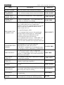
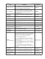
255). Console support 35 different relay control programs. Control program determines state of
output at different states of connected with it partitions. Relay control program description is
shown in the table 3. Description of partition states are shown in the appendix C. Partitions,
partition links with outputs and control programs are setup at customizing (see. item. 2.1.7.4).
Table 7 Relay executive programs
Number
Program name
1
‘On’
2
‘Off’
3
‘On for a time’
4
‘Off for a time’
5
‘Blinking. Normal state
OFF’
6
‘Blinking. Normal state
ON’
7
‘Blinking for a time.
Normal state OFF’
8
‘Blinking for a time.
Normal state ON’
9
‘LAMP’
10
‘Alarm output 1’
11
‘ASPT’
Program description
If ‘Intrusion alarm’ or ‘Fire alarm’ - ON;
else OFF output.
If ‘Intrusion alarm’ or ‘Fire alarm’ - OFF;
else ON output.
If ‘Intrusion alarm’ or ‘Fire alarm’ - ON for a time;
else OFF output.
If ‘Intrusion alarm’ or ‘Fire alarm’ - OFF for a time;
else ON output.
If ‘Intrusion alarm’ or ‘Fire alarm’ - blink (0,5 s ON, 0,5 s
OFF);
else OFF output.
If ‘Intrusion alarm’ or ‘Fire alarm’ - blink (0,5 s ON, 0,5 s
OFF);
else ON output.
If ‘Intrusion alarm’ or ‘Fire alarm’ - blink (0,5 s ON, 0,5 s
OFF) during given time;
else OFF output.
If ‘Intrusion alarm’ or ‘Fire alarm’ - blink (0,5 s ON, 0,5 с
OFF) during given time;
else ON output
If ‘Fire alarm’, ‘Fire prealarm’, ‘Intrusion alarm’, ‘Entry
alarm’ or ‘Arm failed’, then blink (0,5 s ON, 0,5 s OFF);
if ‘Disconnected alarm loop’, “Relay disconnected”, “Fire
trouble”, “Loop open circuit”, “Configuration error”,
“Open relay output ”, “Relay output short circuit”, “Battery
failed”, “AC power failed”, “Power failed”, “2-wire line
short circuit” or “2-wire line trouble”, then blink (0,25 s
ON, 1,75 s OFF);
if there is at least one armed zone, then ON output;
if all zones are disarmed, then OFF output.
If all partitions are armed, then ON (close) outputs;
else OFF (open) output.
ON for a given time, if at least two zones in partition have
‘Fire alarm’ status and there are no zones having states
"Auxiliary alarm", "Relay disconnected", "Open relay
output", "Relay output short circuit". When the failure
removed the relay output will be ON
9
Number
Program name
12
‘SIREN’
13
‘Fire output’
‘Output FAULT’
14
‘Fire LAMP’
15
16
17
‘Turn on for a given time
before arming’
18
‘Turn off for a given
time before arming’
19
20
21
22
23
24
25
10
‘Alarm output 2’
‘Turn on for a given time
when arming’
‘Turn off for a given
time when arming’
‘Turn on for a given time
when disarming’
‘Turn off for a given
time when disarming’
‘Turn on for a given time
if arming has failed’
‘Turn off for a given
time if arming has
failed’
‘Turn on for a given time
when auxiliary alarm’
FIRE AND ALARM CONSOLE
Program description
If ‘Fire alarm’ then blink given time (1,5 s ON, 0,5 s OFF);
if ‘Attention’, then blink given time (0,5 s ON, 1,5 s OFF);
if ‘Intrusion alarm’, then ON for a given time;
else OFF output.
If ‘Fire alarm’ or ‘Fire prealarm’, then ON (close) outputs;
else OFF (open) output.
If there are zones in the states
‘Disconnected alarm loop’, “Relay disconnected”, “Fire
trouble”, “Loop open circuit”, “Configuration error”,
“Open relay output ”, “Relay output short circuit”, “Battery
failed”, “AC power failed”, “Power failed”, “2-wire line
short circuit” or “2-wire line trouble”
or “Disarmed”, “Disarmed and ready” “Disarmed and not
ready”,
or “Arming has failed”, then OFF (open) output.;
else ON (close) output.
If ‘Fire alarm’, ‘Fire prealarm’, ‘Intrusion alarm’, ‘Entry
alarm’ or “Arming has failed”, then blink (0,5 s ON, 0,5 s
OFF);
if ‘Disconnected alarm loop’ or ‘Fire alarm’, then blink
(0,25 s ON, 1,75 s OFF);
if state of all relay associated zones is ‘Zone armed’, then
ON;
else OFF output.
If all zones are armed or disarmed, then ON;
else OFF output.
If at least one zone is in “Arming delay” state, then ON for
a given time;
else OFF output.
If at least one zone is in “Arming delay” state, then OFF
for a given time;
else ON output.
If at least one zone is armed, then ON for a given time;
else OFF output.
If at least one zone is armed, then OFF for a given time;
else ON output.
If at least one zone is disarmed, then ON for a given time;
else OFF output.
If at least one zone is disarmed, then OFF for a given time;
else ON output.
If at least one zone is in the state ‘Arm has failed’, then ON
for a given time;
else OFF output.
If at least one zone is in the state ‘Arm has failed’, then
OFF for a given time;
else ON output.
If at least one zone is in the state ‘Auxiliary alarm’, then
ON for a given time;
else OFF output.
S2000M
Number
26
27
28
29
30
31
32
33
34
35
36
37
38
39
40
MAINTENANCE GUIDE
Program name
Program description
‘Turn off for a given
If at least one zone is in the state ‘Auxiliary alarm’, then
time when auxiliary
OFF for a given time;
alarm’
else ON output.
‘Turn on when
If at least one zone is disarmed, then ON;
disarmed’
else OFF output.
‘Turn off when
If at least one zone is disarmed, then OFF;
disarmed’
else ON output.
‘Turn on when armed’
If at least one zone is armed, then ON;
else OFF output.
‘Turn off when armed’ If at least one zone is armed, then OFF;
else ON output.
‘Turn on when auxiliary If at least one zone is in the state ‘Auxiliary alarm’, then
alarm’
ON;
else OFF output.
‘Turn off when auxiliary If at least one zone is in the state ‘Auxiliary alarm’, then
alarm’
OFF;
else ON output.
‘ASPT-1’
ON for a given time, if at least one zone in partition have
‘Fire alarm’ status and there are no zones having states
"Auxiliary alarm", "Relay disconnected", "Open relay
output", "Relay output short circuit". When the failure
removed the relay output will be ON
‘ASPT-A’
ON for a given time, if at least two zones in partition have
‘Fire alarm’ status and there are no zones having states
"Auxiliary alarm", "Relay disconnected", "Open relay
output", "Relay output short circuit". When the failure
removed the relay output will not be on
‘ASPT-A1’
ON for a given time, if at least one zone in partition have
‘Fire alarm’ status and there are no zones having states
"Auxiliary alarm", "Relay disconnected", "Open relay
output", "Relay output short circuit". When the failure
removed the relay output will not be on
"Turn on with
ON for a given time when the temperature has exceeded
temperature increasing" "temperature high" threshold (in “High temperature”
status);
else OFF output.
" Turn on with
ON for a given time when the temperature has being below
temperature decreasing " "temperature low" threshold (in “Low temperature” status);
else OFF output.
"Turn on during
ON for a given time during launching delay counting
launching delay"
before automatic fire extinguishing system starting (in
"Launching delay" state);
else OFF.
"Turn on during
ON for a given time if launching pulse for automatic fire
launching"
extinguishing system has been given ("Launching" state);
else OFF.
"Turn on during
ON if launching has been confirmed (in "Extinguishing"
extinguishing"
state);
else OFF.
11
Number
41
42
43
44
45
Program name
"Turn on if launching
failed"
"Turn on when
autoextinguishing is on"
"Turn off when
autoextinguishing is on"
"Turn on if
autoextinguishing is off"
"Turn off when
autoextinguishing is off"
FIRE AND ALARM CONSOLE
Program description
ON if launching has been failed (in "Launch fault" state);
else OFF.
ON in "Auto extinguishing" state;
else OFF.
OFF in "Auto extinguishing" state;
else ON.
ON in "Manual extinguishing" state;
else OFF.
OFF in "Manual extinguishing" state;
else ON.
Comments for executive programs:
1) Devices ‘S2000-SP1’ ver 1.20 and ‘S2000-4’ ver 1.07 support extended relay output
controlling, e.g, delayed controlling or control time being given in the range from 0 to 8191,875
seconds and 1/8 second resolution. In addition these devices support various types of blinking
differing by period and pulse ratio. If the equipment does not support extended output relay
control, it cannot allow delayed controlling, blinking can be realized with frequency 1 Hz and
pulse ratio 2 only, control time can be given in range from 0 to 255 seconds with 1 second
resolution.
2) One can give the the delayed controlling for all programs except №№ 9, 10, 13, 14,
15, 16.
3) Outputs with permanent executive programs (e.g, “On” or “Alarm output”) are turned
on (both for opening and closing) when meeting the appropriate conditions and retain in such
state until the condition avoids. After condition disapearing relay outputs return to initial state.
On the contrary to permanent executive programs outputs with time given programs (that is with
limited control time) return to initial state not only when disappearing conditions but if the time
has elapsed. Time given programs will operate identically with permanent programs if given
time has the maximum value being equal 8191,875 second.
4) Programs №№ 11, 33, 34 and 35 are designed to control the fire automatic equipment
including autoextinguishing devices. According to the autoextinguishing systems requirements
one can activated the extinguishing equipment on premises when there is fire alarm in two
independent fire alarm loops checking this premises. To avoid the leak of extinguishing
compound (gas, powder) it is allowed to start the equipment only if all doors are opened. In
addition it is necessary to check the light and audible annunciators control circuits and block up
the fire extinguishing launching when such circuits troubles. The door state is controlled by
means of alarm loops known as auxiliary. If such loop is broken (i.e. the door is opened) it takes
the “Auxiliary loop alarm” status but if close door condition restored this loop automatically
restore its state after auxiliary loop recovery time. To control light and audible annunciators one
can use “S2000-KPB” outputs being able to control short or open failures of load circuit. Output
executive programs are realized so that launching is blocked up if auxiliary loop or output circuit
is failed. As mentioned above to create automatic fire extinguishing controlling the premises is to
be controlled by at least two fire alarm loops, the doors are to be monitored via auxiliary alarm
loops and annunciators are to be controlled by means of “S2000-KPB”. This loops and outputs
form one fire partition associated with one or more outputs designated to give the launching
pulse and being controlled by “ASPT” program. It two or more fire loops in partition alarm the
relay output turns on with given time and delay provided all doors are closed and annunciators
are operative. If at least one door is opened or at least one annunciator circuit is failed the relay
does not start. If two latter conditions disappear with fire alarm being retain then outputs
12
S2000M
MAINTENANCE GUIDE
supplied with №11 (“ASPT”) and №33 (“ASPT-1”) programs will be turned on with given
delay, but outputs supplied with №34 (“ASPT-A”) and №35 (“ASPT-A1”) programs will not be
turned on (in the last case will be turned on if control time restrictions are not given). There are
other distinctions between programs. Starting of relay outputs supplied with №34 and №35
programs is blocked up if there are blocking conditions in any associated partition. On the
contrary output supplied with №11 or №33 programs will be turned on if there is at least one
partition met the launching condition (specifically there are fire alarms and there are no broken
auxiliary alarm loop and failed outputs) without regard to another concerning partition states.
5) Executive programs №11 (“ASPT”) and №34 (“ASPT-A”) allow to turn output on
when either two smoke or heat detectors in partition have been activated or a manual fire
detector (IPR) has been started if the type “Manual launch” for IPR controlling zone was
configured.
6) Output ‘FAULT’ is used to control the operative status of fire partitions. Output
opening follows with:
9 short circuit, open circuit or fault of fire detector,
9 short or open circuit of output relay,
9 connection loss between the console and RS-485 lined control receiving device or relay
unit, or between 2-wire connected addressable detector or relay unit and “S2000-KDL”
controller,
9 short circuit or trouble of 2-wire addressable line,
9 primary or backup power supply troubles,
9 “Disarmed” or “Arming has failed” status of partition.
As this output is normalle closed the relay unit power down or open relay output circuit
are considered to be fault signals.
7) “Fire LAMP” output differs from “LAMP” by turning on only when all assigned
partitions are armed.
8) Program №17 (‘Turn on for a given time before arming’) can be used for 4-wired
detectors auto reset when arming. To do this the detectors are powered through normally closed
contact of ‘S2000-SP1’ device relay output. This output is given by the executive program №17
and control time sufficient to reset detectors. For 4-wired detectors alarm loops the arming delay
is to be given. Arming delay must be more then the sum of resetting time and maximum restore
time of detectors after power reset. As a result when arming command is given the relay will turn
on for given time with 4-wired power circuits being broken and thus reset activated detectors.
9) Programs № 38-45 can be used in gas, powder or aerosol fire extinguishing systems
based on “S2000M-ASPT” devices. These programs allow turning on or off device outputs both
for given time or as long as on/off condition is in effect. Controlling without time restrictions is
realized by givening the maximum control time value being egual to 8191,875 seconds.
Program № 38 "Turn on during launching delay" can be used for activating audible alarms and
light boxes “GET OUT!” and “KEEP OUT!” when launching delay.
Program № 39 also can be used in gas extinguishing system for several areas with the common
extinguishing installation with each area being protected with singular “S2000-ASPT” device.
“S2000-ASPT” devices control fire detector statuses and in case of fire generate launching
message and open gaseous discharge valve to protected area. The console can activate the fire
extinguishing system in “Launching” condition for any area giving out launching pulse to output
provided with executive program № 39 "Turn on during launching".
Program № 41 "Turn on if launching failed" can be used for launching of redundant fire
extinguishing installation.
1.2.23 Console allows assigning up to 32 entrance zones. Entrance zone represents alarm
loop with alarm delay ability. Alarm delay permit to enter the protected area through entrance
zone without immediate alarm and to disarm the premises. The delay factor can be given from 0
to 254 s. Entrance alarm loop being broken the console gets out the message ‘ENTRY ALARM’.
13
FIRE AND ALARM CONSOLE
If after delay elapsing entrance zone has been retaining in alarm, that is was not armed or
disarmed, the console generates “INTRUSION ALARM” message. Relay controlling programs
operate ‘INTRUSION ALARM’ and ‘ENTRY ALARM’ states by different ways (see Table 7).
For example, ‘SIREN’ programmed output is not turned on in ‘ENTRY ALARM’ partition state
with ‘Alarm output’ having being opened. Entrance zones assigned with the help of the console
effect only console controlled output operating algorithm and does not effect on outputs
controlled by intrusion and fire alarm panelss.
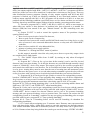
1.3 Delivery set
1.3.1 List of delivery set components of the console “S20000M” is shown in table 8.
Table 8 Delivery set of console ‘S2000M’
Name
Check and control fire-alarm ‘S2000M’ console
Check and control fire-alarm ‘S2000M’ console.
Maintenance guide.
Screw with 1-3х20.016
Dowel 8х35
Printer cable
Personal computer communication cable
Quantity
Note
1
1
3
3
1
1
Supplied for additional price
Supplied for additional price
1.4 Description the product and capabilities
1.4.1 Console has the plastic case. The printed-circuit board is mounted inside the case.
Wires are to be screwed connected to the terminal board. There is the LCD display at the top of
case. Under indicator from the right the LED indicators ‘READY’, ‘ALARM’, ‘FIRE’,
‘TROUBLE’ and ‘FAULT’ are located. Indicator ‘READY’ has green lighting with the others
ones have red lighting. Below indicators there is a keyboard with 20 keys. Keyboard has
supplied with the cover for dust and casual pressure protection. The layout, overall and mounting
dimensions are presented in appendix A.
14
S2000M
MAINTENANCE GUIDE
2 Maintenance
2.1 Preparation the product
2.1.1 General information
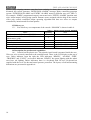
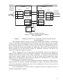
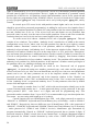
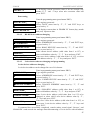
Console uses RS-485 interface to connect fire-alarm system devices, RS-232 interface to
connect printer with consequence interface or personal computer, and contacts to connect
reserved DC power supply. For additional price printer and computer connection cables are
supplied. Typical connection circuit is shown on the Figure 1.
Power
supply
0V
U
S2000М
1
2
Printer
XT1.1
XT1.3
0V
+U
GND
TxD
DTR
1
green
7
5
6
brown
white
GND 7 7
GND
RxD 3 3
RxD
DTR 20 20 DTR
COM
Plug
(DB25F)
DB25M
XT1.2
A
B
3
4
Device
RS485A
RS485B
Device
RS485A
RS485B
С2000М – fire check and control console;
Device – one of the "Signal-20", " Signal-20P", "S2000-4", "S2000-KDL", "S2000-SP1", "S2000-К",
"S2000-КS", "S2000-BI", "S2000-IТ" or "S2000-2";
Printer – printing device with serial interface RS-232
(e.g, Epson LX-300 or LX-300+);
1 – printer connection cable;
Power supply – DC power supply from 10,2 to 28,4 V current supply no more than 150 мА.
Figure 1
Typical maintenance connection ‘S2000M’ console circuit
Attention! On the console board there is 5-pin auxiliary slot. It is prohibited to set pin
tampers or shortly connect the pins if console power is on.
At mounting fire-alarm signal system console and other devices has to be customized.
First of all, each device connected to console through ‘RS-485’ interface has to have unique
network address. Panel cannot poll devices if they have identical addresses. Address values from
1 to 127 are valid. See item 2.1.2 for details. More over, each device has set of configuration
parameters, which determine its work algorithm. Changing values of the parameters, devices
work algorithms can be changed according system requirements (item 2.1.3). Addresses for
15
FIRE AND ALARM CONSOLE
devices, which connected to 2-Wire addressable line of ‘S2000-KDL’ devices, must be also
configured (item 2.1.4).
To customize the control by relay units ‘S2000-SP1’, indicator units ‘S2000-BI’,
keyboards ‘S2000-K’ and ‘S2000-KS’, informators ‘S2000-IT’ console have to be configured.
Also at configuration user passwords and their rights, partition and user text descriptions have to
be set. See details in the item.
If in the system ‘S2000-4’, ‘S2000-2’ or ‘S2000-KDL’ devices are used, which contain
Touch Memory keys and Proximity cards for local control by loops or by access, it is
recommended to program these keys in console and to set test description for them. Otherwise,
device event do not contain user identificator.
2.1.2
Connection console and devices to RS-485 interface instructions
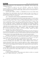
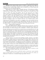
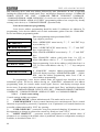
To connect devices and console to the RS-485 interface their contacts ‘A’ and ‘B’ need to
be connected to the A and B interface lines. It is supposed that RS-485 interface use connection
of type ‘bus’ between devices, that is all devices connected through interface by one pair of
wires (A and B lines), matched at two sides by matching resistors (Figure 2). Resistor rating
value is 620 Ohm. They are set at first and at last devices in the line. In ‘Signal-20’, ‘Signal-20’
series 02, ‘Signal-20P’, ‘S2000-4’, ‘S2000-SP1’ and ‘S2000-KDL’ devices matching resistance
is set on the board and can be connected in the line by setting jumper. In ‘S2000’, ‘S2000-K’ and
‘S2000-KS’ devices matching resistance – jumper - is absent. So it is recommended for the first
and the last device in the line to set jumper (for ‘Signal-20’, ‘ Signal –20P’, ‘S2000-4’, ‘S2000SP1’) or resistor 620 Ohm between contacts ‘A’ and ‘B’ (for ‘S2000’, ‘S2000-K’ and ‘S2000KS’). At all other devices jumpers should be removed.
‘S2000M’ console can be set at any place in the RS-485 line. If it is first or last device in
the line, then between contacts ‘A’ and ‘B’ matching resistor 620 Ohm need to be set. Branches
in the line are not undesirable, because they increase reflection signal in the line. But they can be
if length of branch is short enough. Matching resistor is not setup at separate branches.
Resistance of each interface line (A or B) from console to the most remote device has to
be no more 200 Ohm. In the presence of strong external electromagnetic field it is recommended
to use winding pair. Devices and console ‘0 V’ circuits have to be connected. It is no need to
connect ‘0 V’ circuits, if console and devices connected to the one power supply.
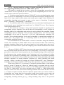
To extend connection line length RS-485 interface repeaters with automatic area
transmission switching can be used (Figure 3). For example, ‘S2000-PI’ interface converter repeater with galvanic isolator allow to extend line length up to 2000 m, implement galvanic
isolation between line segments and automatically off short circuit segments of RS-485 interface.
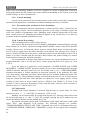
‘0 V’ circuits of isolate segments do not connected. Also repeaters can be used to build ‘star’
configuration (Figure 4).
Attention! Each console connected through RS-485 interface device must have unique
network address. Network address saved in the nonvolatile device memory, it is default value is 127. For each connected device unique address must be set. To do this follow sequence of
actions shown below:
a) connect one device to the console;
b) when panel detected device, set personal network address by address set command
(item 2.2.4.2). Address values from 1 to 127 are valid;
16
S2000M
MAINTENANCE GUIDE
c) connect next device and by identical way set another network address, different from
first one;
d) by this way connect the rest devices, setting unique addresses.
below 3000 m
"RS-485 (A)"
PKU
620 Ом
620 Om
"RS-485 (B)"
PKP
PKP
IP
IP
IP
Figure 2
R
PKP
PKU – console "С2000М";
PKP – alarm panel;
IP – UPS 12V/24V.
IP
Below 2000 m
R
P
IP
PKP
PKU – console "S2000M";
PKP – alarm panel;
P – interface repeater;
Figure 3
"0 V"
Device RS-485 interface connection circuit.
Below 2000 m
PKU
PKP
R
PKP
Below 2000 m
R
PKP
P
IP
R
PKP
R
PKP
IP – power supplier;
R – matching resistance 620 Ohm.
Extend line length with the help of RS-485 interface repeaters
17
FIRE AND ALARM CONSOLE
below 2000 m
S2000M
"RS-485 (A)"
R
R
"RS-485 (B)"
S2000-PI
Receiving
control
device
S2000-PI
R
below 2000 м
R
R
Figure 4
Receiving
control
device
Receiving
control
device
Receiving
control
device
Receiving
control
device
R
Built ‘star’ configuration with the help of interface repeaters
Sometimes there is need to connect console to devices through radio channel, radiorelay
channel, fiber or other connection lines. To interface RS-485 channel with connection channel
equipment with RS-232 input or ‘RS-485’ input and having next data transmission parameters
and: speed transmission 9600 bit/s, word length 8 bit, without check even parity, 1 stop bit. If
equipment with RS-232 output RS-485 interface signals have to be converted in RS-232
interface signals by RS-232 – RS-485 converter (for example, ‘S2000-PI’). Similarly at the other
side of the connection line RS-232 signals need to be converted in the RS-485 interface signals.
As a rule, at data receiving-transmission equipment has own noises. More over, it may have
significant receive-transmit switching time. If the timeouts are above acceptable values, console
will not detect devices or connection will be unstable. For example, if transmission equipment
imports delay 3 ms, then ‘S2000M’ console receive reply from device more then 6 ms after
request. Because console waits reply from device no more 5 ms, device will not be detected. To
solve these problems few connection parameters made customizable. There are standby time at
duty cycle poll, device search, at command, and set of customizable delays before transmission.
If equipment distortion is only data transmission delay, it is just enough to increase polling
latency time. In more complicated cases, it is need to increase device delay before reply and
console pauses, if equipment switches from receive to transmission too long. It is need to keep in
mind that if pauses values increase then device polling time decrease. Console connection
parameters are customized by ‘pprog.exe’ program, device connection parameters – by
‘uprog.exe’ program. Programs ‘pprog.exe’ and ‘uprog.exe’ are free and can be downloaded at
site www.bolid.ru.
2.1.3 Setting device configuration parameters
One can configure such device parameters as alarm loop type, transmission delays from
one operating mode to another (arm delay or fire delay), alarm loop connection with output keys,
work algorithm (control program) of output keys and others. Configuration parameter values
saved in the device nonvolatile memory. Program and control device configuration can be done
18
S2000M
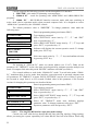
MAINTENANCE GUIDE
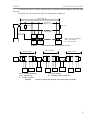
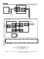
with the help of personal computer and utility ‘uprog.exe’. To connect devices to personal
computer RS-232 – RS-485 interface converter needed (‘PI’, ‘PI-GR’ or ‘S2000-PI’). ‘S2000M’
console can be used as interface converter, transmitted in program mode. Connection circuit of
devices in programming at personal computer with ‘S2000M’ using shown on Figure 5.
2.1.4 Address setting of addressable expanders
If ‘S2000-KDL’ controller used in the system with address devices connected to the 2wire addressable communication line each device unique address (address set) has to be set
Expanders ‘S2000-AR1’ and ‘S2000-AR2’ addresses can be set with the help of console or
‘uprog.exe’ program. It is strongly recommended to program extender’s addresses before
mounting, because when address is programmed controlled extender circuits is used. Description
of the extender address changing with the help of console is shown in the item 2.2.4.3.
S2000М
PC
XT1.3
1
RxD
2 2
RxD
TxD
3 3
TxD
GND
5 5
GND
COM
(DB9M)
brown
yellow
green
RS-485
To devices
XT1.2
5
TxD
A
3
6
DTR
B
4
7
GND
DB9F
PC – personal computer,
S2000M – check and control console "S2000M",
1 – connection cable "S2000" to the personal computer
Figure 5
‘S2000’ console connection circuit. It is configured by personal computer through
RS-232 interface. Also it is shown using it as RS-232 – RS-485 interface
converter.
2.1.5 Printer connection to console or ‘ARM S2000’
If console is used with printer, the last one has to be set for next parameters according
instruction:
Description
Interface type
Transmission type
Number bit
Parity check
Code page
Auto line feed
Setting name in LX-300+
I/F mode
Baud rate
—
Parity
Character table
Auto line feed
Value (in LX-300+)
Serial or Auto
1200 BPS
—
None
PC 866
Off
On the site www.bolid.ru one can download instruction for configuring ‘S2000M’
consoles for working with printer Epson LX300+. Epson LX300 and Epson LX300+ printers
have built-in customizing instruction.
Printer is connected to ‘S2000M’ console with the help of Printer cable (see section 1.3).
Connection circuit is shown on the Figure 1.
19
FIRE AND ALARM CONSOLE
It is possible use personal computer instead printer to log events. To do this, for example,
program Hyper Terminal from Windows or Telemax from Norton Commander 5 can be used.
COM – port must have next parameters: transmission speed - 1200 bit/s, 8 bit, without parity.
Console is connected with help of printer cable and connector to free computer COM - port. If
computer has 9 – contact COM – port socket, connector DB-25F – DB-9F required, and for 25 contact COM – port socket DB-25F – DB-25F connector. At connection to the 9 – pin computer
COM – port contact console outputs hav to be connected next way: console output ‘TxD’ is
connected to 2 output COM – port contact , ‘DTR’ output – to 4 output, output ‘GND’ – to
output 5.
‘ARM S2000’ program is much more convenient, provided by ‘Bolid’. The target of the
program is display and preview console events. More over, program has additional features:
- Adding in event log additional information from device and console configuration files:
partitions and zones names, user names;
- Highlighting by different color messages of different categories (fires, alarms, faults and so
on);
- Displaying states of partitions, zones and devices;
- Event filter allow select events (by time and date, partition number, event categories);
- Connection of several clients operational places working with event log. Connection is made
by TCP/IP protocol;
- Printing event log and export in the HTML format.
Program can work periodically to read messages from ‘S2000’ console. It is possible
‘S2000’ has buffer for 1023 events.
Connection console to personal computer with ‘ARM S2000’ is shown on the Figure 5.
In program ‘ARM S2000’ ‘S2000 1.2х’ source message and address should be set. By perforce
console address can be changed (see item 2.2.4.7).
Attention! For work with ‘S2000M’ consoles of version 1.20 ‘ARM S2000’ program
must be version 1.06 or above.
2.1.6
Using the console for “ARM Orion” redundancy
‘S2000M’ console can be used in systems running ‘ARM Orion’ for stand-by controlling
when PC fails. It is very important with the aim of surviving and robustness for fire alarm and
fire auto extinguishing systems.
There are two approaches or modes to build the backup controlling with the help of
‘S2000M’ console, each heaving some conveniences and disadvantages.
The first backup mode named ‘S2000 / PC’ is to make ‘ARM Orion’ monitors all
devices and registers states of them with ‘S2000M’ console being aside. If the computer has
failed the console automatically connect the devices and take over the control. When recovering
the computer assume the control again.
This backup mode is suitable for using the console coupled with any ‘ARM Orion’
software version providing the unlimited computer controlling of the system.
The disadvantages of this mode are as follows:
1) The console and ‘ARM Orion’ are in operation without reference to each other. Messages
receiving by the console cannot be obtained by the computer when having restored. On the
other hand messages receiving by ‘ARM Orion’ are not registered by the console.
20
S2000M
MAINTENANCE GUIDE
2) There is some switching delay required when the control is taken over for false switching
protection, device detection period and for initiation. The more system is greater the more
switching delay is needed.
The switching criterium is the absence of computer polling during given time.
There are two ways of switching the control from PC to the console: 1) by means of selfacting mechanically RS-485 lines switching with the help of “S2000M-SP1” relay units and 2)
using the special console operating mode, that is interface converter mode with automatic transit
to redundant mode.
The first way supposes the console to be physically disconnected and is described by the
“S2000M-SP1” maintenance guide. One shoulde use the “S2000M-SP1” device version 1.20 or
above.
The second way supposes the console to be directly connected to the computer via RS232 interface, with the the devices being connected to the console through RS-485 interface.
Being operative ’ARM Orion’ polls all the system devices but the console execute the
RS-232/RS-485 convertor function without galvanic separation. The console doesn’t control
devices, doesn’t show their states and is unresponsive to key pressions. LCD displays the “S2000
/ PC” string and the “READY” indicator blinks to show the data transmission.
If the computer doesn’t poll the devices during a given time period then the console
automatically switches to the active mode. The switching delay is nesessary against false
switchings due to the polling intervals.
To configure this switching way set the RS-232 operating mode to the “S2000 / PC”
value and give the switching delay as described in section 2.2.4.8. It is recommended to set the
switching delay at least 60 seconds.
Two above switching ways are just alike in terms of capabilities. Their benefits in
comparison with each other are as follows:
switching by means of ‘S2000-SP1’
switching from “S2000 / PC” mode
1) The galvanic isolation is like to be at less 1) in case of sophisticated system it is more
cost
suitable for usage of several consoles for
2) Old messages stored by the console in
redundancy
backup mode are available
2) when switching the controlling from the
3) It is possible to connect printer to the
console to the PC the console will not give
console
messages about device disconnections
The second reserving mode called as ‘S2000 & PC’ is that the console is to be directly
connected to the computer via RS-232 interface, with the the devices being connected to the
console through RS-485 interface. The console monitors all the devices and gets their states,
with the computer polling the concole (or consoles) and getting the device operative information.
Both the console and the computer can control the relay outputs and indication units. If the
computer fails the console will retain to execute the controlling functions. This reserving mode
has the following advantages:
1) The devices are available for controlling by the console when the PC operates normally. If
the PC supplied with ‘ARM Orion’ software failes the event messages are storied in the
console buffer and can be readed after the computer restoring.
2) As a result of absence of switching between the console and PC there is no switching delay.
3) Delegating the console some controlling functions unloads the PC.
21
FIRE AND ALARM CONSOLE
To realize the second reservation mode it is necessary to assign the console with the
address and set the RS-232 operating mode to the value “S2000 & PC”. Refer to the section
2.2.4.8 for more details.
The following Table 9 summarizes the essentials of all available backup techniques.
Table 9 Available backup techniques
№
Technique
Disconnected
console
1
and relay
switching
Technique description
Configuration method
The monitoring and controlling are carried out
from the computer. The console is active but
disconnected from the system. When the PC
has stopping poll the devices for given time the
console has automatically connected to the
devices with the help of “S2000M-SP1” relay
unit.
In accordance with the
“S2000M-SP1” relay unit
maintenance guide
The monitoring and controlling are carried out
from the computer. The console is directly
connected to the computer via RS-232
Passive
interface, with the the devices being connected
console
to the console through RS-485 interface. The
2
and automatic console doesn’t control devices, doesn’t show
switching
their states and is unresponsive to key
pressions. When the PC has stopping poll the
devices for given time the console has
automatically switches to the active mode.
The console is directly connected to the
computer via RS-232 interface, with the the
devices being connected to the console through
RS-485 interface. The console monitors all the
devices and gets their states, with the computer
3 Active console polling the concole (or consoles) and getting
the device operative information. Both the
console and the computer can control the relay
outputs and indication units. If the computer
fails the console will retain to execute the
controlling functions.
In accordance with the
2.2.4.8 section ot this
maintenance guide set
RS-232 operating mode to
the “S2000 / PC” value
and give the switching
delay
In accordance with the
2.2.4.8 section ot this
maintenance guide set
RS-232 operating mode to
the “S2000 & PC” value
and give the own console
address
Note that the techniques 1 and 2 are obsolete but technique 3 is recommended.
Figure 5, Figure 6 and Figure 7 demonstrates the connection diagrams.
Figure 5 shows the simplest way to connect the console to the computer. The defect of
this way is the galvanic coupling between the PC and system devices through the RS-232
interface. This galvanic coupling result to the devices or RS-485 interface and the PC interfere to
each other.
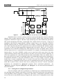
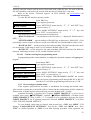
To isolate the PC from intrusion and fire alarm panelss the RS-485 interface repeaters
with galvanic isolation, e.g, “S2000-PI”, can be used. The connecting diagram providing
galvanic isolation RS-485 line by ‘S2000-PI’ device is shown on the Figure 6. Note that to
provide isolation the console and interface repeater should be powered by separate source
without ‘0 V’ circuit of this source coupling with the ‘0 V’ devices circuit.
22
S2000M
S2000М
RS-232
computer
COM-port
1
MAINTENANCE GUIDE
S2000-PI
XT1.3
5
TxD
6
DTR
7
GND
XT1.2
XT1
XT3
A
3
1
A
B
4
2
B
A
1
3
GND
B
2
XT4
0В
3
XT1.1
0V
1
2
GND
+ Us
2
1
+U
BP
ISOLATED
RS-485
To devices
+
–
S2000М –‘S2000M’ alarm panel;
S2000-PI – interface converter repeater "S2000-PI";
BP – power supply.
Figure 6
‘S2000M’ PC with AUP ‘Orion’ with galvanic isolation of interface RS-485
connection diagram
The ‘S2000M’ database storage is far less then ‘ARM Orion’ database. It prevents the
creation of backuping if system has more than 2048 alarm loops and 511 partitions. It is possible
to reserve the PC by several ‘S2000M’ consoles. One can connect only single console to the PC
RS-232 interface therefore it is necessary to convert RS-232 interface to the RS-485 interface by
means of ‘S2000-PI’ which several consoles are connected to. The consoles are connected to the
RS-485 interface line by their RS-232 outputs via ‘S2000-PI’ convertors. The devices are
connected to the RS-485 outputs of consoles.
Figure 7 displayes the way of connecting several ‘S2000M’ consoles to the computer. In
addition to the capability of several consoles the ‘S2000-PI’ convertors provides the galvanic
isolation between the PC and the console. When ‘ARM Orion’ reserving by several consoles the
system device number should not exceed 127 and all system devices should have unique
addresses. If the computer failes each console will control own connected devices, i.e, the system
will disintegrate to several unrelated subsystems.
For regardful reserving the consol configuration should correspond to 'ARM Orion' or
'ARM Orion Pro' one given by “Database Administrator” program. The structure and the names
of the zones and partitions should be the same in both configurations. The user names given for
the same password are to be identical.
It is recommended to to write the console configuration from the computer by means of
“Database Administrator” program.
23
FIRE AND ALARM CONSOLE
S2000-PI
XT3
XT5
yello
PC
white
1
COM
brow
gree
1
2
3
4
GND
TxD
RxD
+5В
RS-485
ISOLATED
A
B
0В
To consoles
1
2
3
Keyboard
To keyboard
PC
subsystem № 1
XT3
ISOLATED
1
2
3
S2000М
XT1.3
XT1.2
S2000-PI
XT5
GND
TxD
RxD
+5В
A
B
0В
XT1
GND
+U
BP
1
2
3
4
2
1
7
6
5
GND
DTR
TxD
A
B
RS-485
To devices
3
4
XT1.1
1
0В
2 + Uп
+
–
subsystem № 2
To all subsystems
S2000М –‘S2000M’ alarm panel;
S2000-PI – interface converter repeater "S2000-PI";
BP – power supply;
1 – connection cable "S2000-PI" and PC.
Figure 7
24
Connection of several ‘S2000M’ to the PC with ‘ARM Orion’ with galvanic isolation
of interface RS-485 diagram
S2000M
2.1.7
2.1.7.1
MAINTENANCE GUIDE
Console configuring
General information
If it is required to use ‘S2000-SP1’, ‘S2000-BI’, ‘S2000-K’, ‘S2000-KS’, ‘S2000-IT’
devices in the system, then console must have control rules of the devices. These rules are setup
when console is configuring.
Creating the console configuration can be done only with the help of personal computer
and program ‘pprog.exe’ version 2.04 and above. The program is free. It is available on the site
www.bolid.ru
Console configuration steps are:
1) Run program ‘pprog.exe’. Read configuration from console or file, or create new one;
2) Correct it if necessary and save in file;
3) Write ready configuration in file.
To create new configuration by means of ‘pprog.exe’ select command ‘Create’ in menu
‘File’, or press button ‘Create new configuration’. Select console version, and press ‘OK’. The
default configuration will be created and it can be edited if necessary.
To read present configuration select command ‘Open’ in menu ‘File’, or press button
‘Open configuration file’. In window ‘Open file’ select file type, select file and press button
‘OK’. There are two available types of configuration files: text (with TXT extension) or
encrypted (with GPC extension). To read encrypted configuration file it is necessary to enter
engineer password.
To write configuration in the file select command ‘Save’ or ‘Save as’ in ‘File’ menu, or
press button ‘Save configuration file’. Configuration can be saved in text or encrypted file.
Edited configuration can be saved in a file, loaded from a file, written to the console
nonvolatile memory, or read from the console memory. To write or read the configuration
‘S2000M’ console has to be connected to personal computer. The console can be connected both
via RS-232 or RS-485 interfaces. In the first case console is connected to computer as shown on
the Figure 5, and the second case is shown on the Figure 8.
Set console programming mode:
press ‘PRG’ key;
ENTER CODE:
enter engineer password (default value - <123456>) and press
‘ENT’ key;
select menu item ‘SETTINGS’ by keys ‘t‘ and ‘u‘ and
v5 SETTINGS
‘ENT’, or press key ‘5’;
v REMOTE PROGRAM select menu item ‘REMOTE PROGRAM’ by keys ‘t‘ and ‘u‘
and ‘ENT’, or press key ‘6’;
PROGRAMMING MODE the LCD will display ‘PROGRAMMING MODE’ indicating the
console status.
Console in programming mode allow to write and to read the configuration by means of
program ‘pprog.exe’. When in programming mode the console should have a unique address in
‘RS-485’ interface address range. Its default value equal 127 and can be changed (see. item 0).
Refer to the ‘pprog.exe’ user’s manual for procedures for console configuring. To exit from
programming mode press console key ‘CLR’. The console will return to operating mode and
25
FIRE AND ALARM CONSOLE
request the states of all connected devices loops and so on. It can take few dozen seconds
(typically) or even few minutes (maximal value). After that procedures console is ready.
Before reading and writing of ‘S2000’ console configuration by program ‘pprog.exe’, the
communication between console and program has to be set. Select ‘Devices’ tab, shoose the
console communicated COM-port number and press key ‘Start searching’. Program searchs the
connected devices, showing addresses and types of founded devices in the lower window. If the
console will be founded the reading and writing of the console configuration will be able. Main
menu of ‘S2000M’ include functions ‘Write configuration’ and ‘Read configuration’ for reading
and writing current configuration to the console memory. Read operation takes about 4 minutes,
Write operation - about 4 min 20 sec.
Attention! During writing of the configuration it is prohibited cut off the power of the
console or exit from programming mode. If it is happened, writing operation has to be repeated.
PI
PC
S2000М
XT1.2
COM
RS-485 A
3
A
RS-485 B
4
B
RS-485
To devices
PC - computer,
PI – interface converter RS-232 – RS-485
(for example, ‘PI’, ‘PI-GR’, ‘S2000-PI’),
S2000М - ‘S2000M’ alarm console
Figure 8
‘S2000M’ connection for configuration by personal computer through RS-485
interface
Configuration creating steps:
1) Add required devices into console data base and create the partition;
2) Define the authority levels for partition controlling, assign reguired PIN codes and
registered corresponding Touch Memory keys or Proximity cards;
3) Set the relay output controlling;
4) Set the event reporting to ‘S2000-K’ keyboards and ‘S2000-IT’ informators;
5) Set the entry zones;
6) Create user messages, if it's needed.
These steps are described in sections 2.1.7.3 - 2.1.7.7.
2.1.7.2
Adding devices into console database and partition creation
Device loops can be included in partitions, and their outputs can be automatically
controlled by ‘S2000M’ console, if these devices are presented in console database. To add the
device specify it address and type.
26
S2000M
MAINTENANCE GUIDE
Select ‘Devices’ tab of program ‘pprog.exe’. It can be done by two ways: manually and
from list of polling devices. To obtain the devices list press ‘Start searching’. Program detects
connected devices. Devices are added to the console database by dragging from window
‘Search’ to window ‘Devices’. To add device manually press ‘Add device’ button in the top right
corner of the ‘Devices’ window. In ‘Inspector’ window click the address line and type the
required address (the digit from 1 to 127). Click the type line and select the required value from
the available list. If it is necessary add the description that will be shown only from the
configuration program. New device will be added to the database.
To create partition it is necessary to add new partition, assign it number (from 1 to 4
digits) and to include required zones. The total number of partitions cannot be more then 511.
Optionally one can assign any text descriptor (no more 16 symbols) to zones and to partition.
To add new partition select the tab ‘Partitions’. This tab has two windows. Top window
‘Partition zones’ contains a partition’s tree with zones, the bottom window ‘Device zones’
contains the device tree with zones. Press button ‘Add partition’ in the upper right corner of the
‘Partition zones’ window. In ‘Inspector’ window click the line ‘Number’ and type the unique
number (from 1 to 4 digits). If it is necessary assign the text descriptor to the partition in
‘Description’ line (up to 16 symbols). Parameter value input is finished by pressing key ‘Enter’
on computer keyboard. Adding zones to partition is made by drug-and-drop of zones from
bottom device tree in correspondent brunch of upper partition tree. Program allows dragging
both one zone and group of zones. For group selection use left mouse button with keyboard
buttons ‘Shift’ or ‘Ctrl’. Key ‘Shift’ is used for selecting zone range but ‘Ctrl’ is used for
selective marking. If it reguires to drag all device zones into the partition one can drag the device
itself from device tree.
Zones can be assigned with the text description. Select the reguired zone in ‘Device
zones’ window and click the ‘Description’ line in ‘Inspector’ window. Enter the text string up to
16 symbols.
Partitions can be integrated into groups. There can be created up to 128 partition groups.
To create partition group it should add new group, assign it with a group number (from 1 to 4
digits) and include required partitions. Partition groups can be assigned with the text description
(up to 16 symbols). One group can contain up to 511 of partitions and a partition can member
into several groups.
Note: Group controlling takes more time then partition one especially when a partition is
included into few groups. So it is not recommended if it is not really needed.
To add new partition group select the ‘Partition groups’ tab. This tab has two windows.
Top window ‘Partition groups’ contains a partition group’s tree with partitions, the bottom
window ‘Partitions’ contains the partition list. Press button ‘Add group’ in the upper right corner
of the ‘Partition groups’ window. In ‘Inspector’ window click the line ‘Number’ and type the
unique number (from 1 to 4 digits). If it is necessary assign the text descriptor to the group in
‘Description’ line (up to 16 symbols). Parameter value input is finished by pressing key ‘Enter’
on computer keyboard. Adding partitions to the group is made by drug-and-drop of partitions
from bottom partition list in correspondent brunch of upper group tree.
2.1.7.3
Setting partition control rights and password programming
Access to partition control functions is granted to users at password entering at ‘S2000M’
console, ‘S2000-K’ keyboards or ‘S2000-KS’, or at using Touch Memory key or Proximity card
with ‘S2000-4’ or ‘S2000-2’, ‘Signal-20P SMD’ version 2.01 and above, ‘S2000-KDL’ version
1.15 and above. User gets access to partition control functions if he has corresponded control
rights for these partitions and control is permitted for controlled device, if he has rights. User’s
27
FIRE AND ALARM CONSOLE
rights is determined by access level of its password. Access level determines permitted partition
list and control rights for each partition. Device’s rights are determined by permitted control
partition list of this device. All partition control right information (access levels, password and
device rights) are programming in the ‘S2000M’ console. Access levels and device rights can be
given by program ‘pprog.exe’ only. Passwords can be set by both program ‘pprog.exe’, and by
console.
In console up to 252 access levels with partition control rights can be set. Access levels
should be given before passwords programming. At adding for each access level number from 1
to 252, list of permitted partition for control, for each partition in the list control rights (permit or
not arm, disarm) have to be set. If for access level arm and disarm are not permitted, then
password owner can only view the states of accessible partitions. It has to take into account the
restriction that just 8 access levels can have control rights for the same partition.
To create access level choose ‘Authority levels’ tab of program ‘pprog.exe’. This tab
consists of two windows. Top window ‘Authority levels’ contains tree of added to the console
configuration access levels, where each level has partition list, that he gives right to control.
Bottom window ‘Partitions’ contain list of all partitions, added in configuration. To create
authority level press button ‘Add athority level’. In the inspector window in line ‘Number’ select
authority level number (Number has to be in the range from 1 to 252), and in line ‘Description’
type text name (this parameter is additional and not saved in console). Further in created level it
is need to add partitions for control. Partition is added by ‘dragging’ from bottom window
‘Partitions’ in selected level of top window ‘Authority levels’. The partition will be added in the
authority level partition list. Selected partition, in the inspector’s window control privilegies of
the partition can be set, enabling or denying arm or disarm.
Adding and editing of passwords are made on the ‘Passwords’ tab of program
‘pprog.exe’. At password setting user number, password type, code value and the password
access level have to be set. Also user text identificator can be given. Also user text identificator
(name) can be set. All these parameter are set in the inspector window controls. For new
password press button ‘Add password’ and in the inspector window in line ‘Number’ set
identificator number, in line ‘Code’ set identificator value, in line ‘User’ set user text description,
in line ‘Authority levels’ set password authority level. To edit parameter select line by double
mouse click and input new value.
User number is number from 1 to 2047, which with text description identify user in the
system. Password with number one 1 – is main password always (set up password). It has type
‘main password’ (PIN – code from 1 to 8 digits) and used for programming only. User
passwords can have numbers from 2 up to 2047. It is recommended to type text description also.
User name – any text string with length up to 16 symbols.
Console support two user identification ways: PIN - code (digit password) at console or
‘S2000-K’ or ‘S2000-KS’ keyboards and Touch Memory key or Proximity - cards at ‘S2000-4’
and ‘S2000-2’. Respectively, there are differ two type of identificators: PIN - code (password of
‘S2000-K’, ‘S2000-KS’ keyboards and ‘S2000M’ console) and Touch Memory key or Proximity
- cards (password of ‘S2000-4’ and ‘S2000-4’ devices). Identificator type determined by
program automatically. Entered at ‘S2000-K’ keyboard password has to contain 4 digits. If
password entered at ‘S2000’ console, then it can contain from 1 to 8 digits. Maximum length of
user password for ‘S2000’ console determine by value of the ‘CODE LENGTH’ parameter.
28
S2000M
MAINTENANCE GUIDE
Console finished password enter if number typed symbols equal to value of the parameter.
Parameter ‘CODE LENGTH’ can be in range from 1 to 8 symbols (see item 2.2.4.4).
Identity code is input from the computer keypad or ‘S2000-K’, ‘S2000-KS’,
‘S2000-4’,‘S2000-2’,‘Signal-20P SMD’, or‘S2000-KDL’ devices, provided that they are polled by
means of program ‘pprog.exe’. Reading identifiers from the polled device is faster and more
useful then manual input. Device must be polled by program ‘pprog.exe’ to input identificator
code. If device is not polled, search this device on the tab ‘Devices’ in window ‘Search’. To set
code on tab ‘Password’ press button ‘Read code’ and touch Touch Memory key (Proximity-card)
to the reader. Key (card) code should be read and showed in ‘Code’ field. ‘S2000-KS’ or
‘S2000-K’ keyboard PIN-code should consisit from 4 digits. Such password can be programmed
without ‘pprog.exe’, from console ‘S2000M’. Password programming is described in the item
2.2.4.5.
To set device partition control privilegies select ‘Controlling abilities’ tab of ‘pprog.exe’
program and drag reguired partition from ‘Partition’ window to the corresponding device in the
‘Controlling abilities’ window. In such a way each device is to be assigned with the list of
partitions available for controlling.
Note that TM or Proximity authority level should have controlling privilegies only for
single partition.
2.1.7.4
Setting control by system relay outputs
Console allows organizing up to 255 system outputs (‘open collector’ or relay) which
controlled according to the given algorithm on the basis of the partition states. Because ‘S2000’
console control by system outputs let call such control external (to differ from internal control
when receive-check device control by their outputs itself). To customize outputs it is necessary
select physical relays (device address and relay number in device), which will be used for system
control. Determine partitions that controlled by relay’s state (connect relay and partition).
Determine relay state dependence from state of connected partitions (select control program).
These settings are run by program ‘pprog.exe’ when console configured. Control program
number is selected according Table 7. If output belongs to device, that support extended output
control (for example, S2000-SP1 version 1.20 or S2000-KPB), switching timeout can be set. For
outputs with time restricted program time control should be set. Control time and switching
delay are given in the range from 0 to 8191,875 seconds with interval 1/8 seconds. If control
time equal to 8191,875 seconds, then output will be switching on without time limitation. Setting
these parameters run by program ‘pprog.exe’ when console configured. If device do not support
extended relay control, then their outputs will be switched without delay, and switching time will
be equal to the value of configuration parameter ‘Control time’ this relay. ‘Control time’
parameter is set with the help of the console or program ‘uprog.exe’. Also, for relay outputs of
‘S2000-SP1’ it is necessarily to set value of ‘Control program of initial state’ parameter. This
parameter output state after switching on power of the device. It should be 0 (‘off’) or 1 (‘on’)
depending on console output program. If output control by programs, operated on switching on
(for example, programs ‘On’, ‘On for a time ‘, ‘Siren’, ‘ASPT’), ‘Control program of initial
state’ parameter value have to be 0 (‘off’). Output ‘S2000-4’, ‘Signal-20P’ and ‘Signal-20’ series
02 device initial state determined by parameter ‘Control program’. If output initial state has to be
‘off’, parameter ‘Control program’ has to have value 1, if ‘on’ - value 2. Parameters value
‘Control program of initial state’ and ‘Control program’ can be programmed in device both with
the help of console and with the help of program ‘uprog.exe’.
29
FIRE AND ALARM CONSOLE
Attention! When output external control of ‘S2000-4’, ‘Signal-20P’ and ‘Signal-20’
version 02 devices is used internal control has to be removed, that is outputs have to be not
connected to loops. If internal output control is used it is prohibited to use external control, that
is outputs have to be not connected to partitions.
Relay output is set on the tab ‘Relay’ of program ‘pprog.exe’. Tab contains two windows:
in top window ‘Partitions (relay)’ is displayed partition tree, where for each partition is shown
connected relay list. Bottom window ‘Devices (relay)’ contains tree of all system devices with
relays. To connect relay output with partition, ‘drag’ the relay from device tree (window
‘Devices (relay)’) in corresponded partition in the tree (window ‘Partitions (relays)’). At that
relay will be added to the connected partition list. If output should be controlled by few
partitions, connect it with other partitions the same way. It is possible group connection
partitions and outputs. Few output can be selected by left mouse button and pressed key ‘Shift’
(for range selection) or ‘Ctrl’ (for selective marking), after that there can de added to the
partition. At ‘dragging’ output or few outputs on the tree ‘root’ ‘Partition (relays)’ will be
connected to the all partitions in the system. At ‘dragging’ device to the partition all device
outputs will be connected to the partition. Also control program, start delay, and control time for
the outputs should be set. For that in the window ‘Devices (relays)’ in device tree select relay, in
the inspector window are displayed current parameter values, correct them if necessary.
2.1.7.5
Setting message transmission
It is possible transmit events to ‘S2000-K’ keyboard version 1.04 and above. Keyboards
allow indicating received events on LCD, signalize by internal sound annunciator at alarm event,
have nonvolatile event buffer. Messages can be transmitted to ‘S2000-IT’ phone informators.
Messages should not sent to the other devices, because they are not needed them for work and
delay system operability! For setting events transition to the devices select the devices, which
will receive messages from the console. Messages can be sent independently (translation to the
address), or like broadcast message to all devices at once (common translation). For each device
message categories and partitions for transmission can be set. It allows permitting some type
message transitions (for example, alarms and fires) and prohibit another ones (for example,
arm/disarm alarm loop). Message categories are in appendix Г. Partition list allows send only the
messages from loop of this list.
Message transition is set on tab ‘Event translation’ program ‘pprog.exe’. Top window
‘Event transition’ contain list of devices for message transition from console. Each device has to
have transition permitted partition list. Bottom window can display either system device list
(‘Devices’), or partition list ‘Partitions’. Device list is used for adding devices in message device
list (in window ‘Event transition’). At adding device tree node ‘To all devices’ console messages
will be receive all system devices. Its unload RS-485 line at transmission the same messages to
the large number of devices, but exclude individual message send. For each device, added in
window ‘Message transition’, in inspector next message categories are pointed, which will be
transmitted to it. Also for each device list of permitted message sources (partitions) should be
set. For that in bottom window select partition list and ‘drag’ selected devices.
Also, event transmission to printer can be required. This setting is selection of event
category that has to be printed. Default value is all events are printed.
Attention!
1) Message transition heavily load RS-485 interface, that decrease system operation
speed. To unload interface need to transmit just rare events (such as alarms, fires, faults), use
transmission ‘To all devices’, to transmit messages large number of devices.
30
S2000M
MAINTENANCE GUIDE
2) For displaying console transmitted events by ‘S2000-K’ keyboards their configuration
parameters ‘Event indication’ and ‘Alarm indication’ have to be customized.
3) ‘S2000-K’ keyboards may not support come of the console messages. Such messages
will not be displayed.
4) Transmission speed through phone lines by ‘S2000-IT’ informators is low. That is
why to avoid informatory buffer overflow it is recommended to transmit to informatory just the
most important and rare messages (alarms, fires). To do this needed event categories has to be
permited for transmission, and others have to be forbidden. At informatory buffer overflow it
should be cleared (see item 2.2.3.9).
2.1.7.6
Entry zone settings
Console support up to 32 input zones. Each of them is determined by device address,
alarm loop number in device and alarm delay. Any alarm ALs connected to the device console
can be used as input ALs. Delay can has value from 0 to 254 seconds.
Input zones are setted on tab ‘Entry zones’ ‘pprog.exe’ program. In the top window ‘Input
zones’ contains alarm loop list, set up as input zone. In botton window ‘Devices (loops)’ there is a
list of system devices and its alarm loops. To create input zone ‘drag’ alarm loop from ‘ Devices
(loops)’ window in the window ‘Entry zone’ and in the inspector window ‘Alarm delays’ set (in
seconds) transition delay alarm loop from ‘intrusion alarm’ mode in the ‘alarm’ mode.
2.1.7.7
Setting user messages
Console allows create user messages, which will be displayed and transmitted instead
standard messages. Standard messages rename rules are determined in scripts. Rename script for
each standard message gives new name, sound signal, alarm level and category. Script allows
rename up to 4 standard messages. Console allows create up to 32 rename scripts. Script can be
set for any alarm loop (or few ALs), from console database. If loop rename script is set, then
standard messages of the loop will be replaced to user defined messages, if such replace is in
script. Message renaming is actual for auxiliary alarm loops, which are usually checking state of
an equipment. This possibility permits display, for example, instead of standard messages ‘AUX
ZONE ALARM’ and ‘AUX ZONE RESTORE’ other messages, for example, ‘VALVE OPEN’
and ‘VALVE CLOSE’.
Message renaming is defined on the tab ‘Message renaming’ of ‘pprog.exe’ program.
Create renaming script, select base messages to be renamed, select sound signals, set alarm
levels and select categories of renamed messages. Alarm level determines the priority order for
displaying message by the console LCD if few alarm messages are received. Higher alarm level
value corresponds to the higher displaying priority of alarm messages. Message category is
intended to classify messages with the aim of printing or transmitting to the ‘S2000-K’
keyboards or ‘S2000-IT’ phone communicators. Renaiming script having been created should be
associated with corresponding zones.
2.1.7.8
Controlling ‘S2000-BI’ devices settings
‘S2000M’ panel with programmed partitions can be connected to ‘S2000-BI’ indication
units. Prior, configuration of indication blocks with the help of ‘S2000M’ console or program
‘uprog.exe’ has to be set. Minimal setup is programming partition number for each indicator. At
connecting indication units to ‘S2000M’ console LED ‘S2000-BI’ indicators will show states of
partitions.
31
FIRE AND ALARM CONSOLE
2.1.7.9 Using the console for creating of systems controlling gas, powder or aerosol
fire extinguishing installations based on "S2000-ASPT" devices
The console is suitable in gas, powder or aerosol fire extinguishing systems based on
"S2000-ASPT" devices especially in case of using several extinguishing areas at once. The
console can be used in such systems as follows:
1) To indicate system status by means of "S2000-PТ" devices each displaying the current
status of 10 areas of extinguishing. For each area several status are displayed, among them fires,
faults of fire loops, output circuits, primary and standby power supply, launch blocking, fire
extinguishing launching mode (manual or auto), various statuses of launching ("Launching
delay", "Launching", "Extinguishing", "Launch fault").
2) To control the status of fire extinguishing area, turn auto/manual launching mode and
activate/cancel remote launching from console itself or "S2000-PT" device. These functions
require password-based access.
3) The console has a number of relay control programs designed for operating in fire
extinguishing systems. Programs "Turn on/off when auto extinguishing is on/off" monitor the
launching mode of fire extinguishing units and can be used in particular for controlling "Manual
extinguishing" light box. Programs "Turn on during launching delay" and "Turn on during
extinguishing" can be used for "Keep out!" и "Get out!" light annunciator controlling. The
program "Turn on during launching" can be used for launching of extinguishing installation for
several areas. The program "Turn on if launching failed" can be used for standby fire
extinguishing installation launching.
It is recommended to use "S2000-ASPT" versions 2.03 and above along with "S2000М"
console. The controlling of "S2000–ASPT" devices with versions less than 2.00 is limited by
automatic launching control mode and remote launch in local control mode only (out of
partitions). Such control doesn’t require the configuring of the console and described in section
2.2.3.4.
All zones of “S2000–ASPT” (loops, inner zones and output circuits) should be combined
into one partition which represents one area or fire extinguishing. It is necessary to assign some
passwords for launch mode control operations and for activating/canceling of the remote launch.
For this purpose when creating authority levels ("Authority levels" tab in "pprog.exe") define
partitions that is permitted for controlling (that is extinguishing areas) and assign the permitted
operations for each partition. The permitted operations can be arming, disarming, and turning
automatic equipment on, turning automatic equipment off, remote launching and launch
canceling. Arming is needed for resetting of activated "S2000–ASPT" loops. Disarming is
meaningless in the context of "S2000–ASPT" using. Other operations are given when needed.
When using "S2000–PT" it is necessary to assign the partition number to each indicator
group by means of "uprog.exe". Hence the indicator group is associated with the specific
extinguishing area and displays the status of that area. The "FIRE" indicator shows either if some
fire loops of "S2000–ASPT" have been activated (being in "FIRE" or "FIRE PREALARM"
status), or control zone state (when remote launching command from console has been received
), or manual call point activated. "FAULT" indicator signals if there are various troubles in
extinguishing area, among them fire loop troubles, output circuit troubles, power outage and
disconnection from "S2000–ASPT". "LAUNCH BLOCKED" indicator displays if there is
extinguishing launching blocking up (e.g., during launching delay doors to the protected
32
S2000M
MAINTENANCE GUIDE
premises were opening). "AUTOMATIC MODE" indicator demonstrates the current launching
mode (is auto launching mode on or not). "EXTINGUISHING" indicator demonstrates status of
launching (that is no launching, launching delay, launching or launching failure). "S2000–PT"
devices have some buttons for automatic mode controlling (turn on/off auto extinguishing mode)
and for remote launching or canceling of auto extinguishing equipment launch. "S2000–PT"
device is supplied by input for Touch Memory reader, with Touch Memory keys being used for
getting access control to extinguishing area controlling by means of buttons. Touch Memory
keys have to be recorded into the console configuration with authority level allowing
extinguishing area controlling with the corresponding rights. If the user has no rights the
controlling by means of buttons is impossible. "S2000–PT" may be supplied with inner password
for extinguishing area controlling, without Touch Memory key identification. It can be used
when "S2000–PT" unit is located in secured place. The password (PIN-code) can be recorded to
"S2000–PT" device by means of "uprog.exe" program. This password with authority level
allowing extinguishing area controlling has to be recorded to "S2000М" console.
The console allows controlling the additional relay outputs, such as annunciators
common for several areas or common extinguishing installation. Refer to the 2.1.7.4 section of
this manual for procedures for relay output control settings.
2.1.7.10 Using the console with sprinkler or drencher extinguishing units based on
devices "POTOK-3N"
The console can be used for displaying the status of sprinkler or drencher fire
extinguishing system via the indication units "S2000–BI(01)".
The indication unit "S2000–BI(01)" is designed to display only one area of fire
extinguishing. The extinguishing area is represented by the pump station, one or two duty
pumps, standby pump and jockey pump. Create the partition for pump station and one partition
for each pump when configuring the console.
Include "Potok–3N" device zones controlling the status of pump station into the pump
station partition and zones controlling the status of pumps into the pump ones. For the first duty
pump use zone № 1 (which controls turning on/off and pump faults), zone № 11 (controls the
power outages) and zone №21 (automatic control mode). For the second duty pump use zones
with the numbers 2, 12 and 22 respectively, for the standby pump use the numbers 3, 13, 23 and
finally for jockey pump use the numbers 4, 14 and 24. Depending on "Potok–3N" device
configuration some pumps may be absent and the corresponding zones controlling such pumps
might be displayed as "Disconnected alarm loop" status. So don’t create any partition for lacking
pumps. The pump station itself is controlled by zones number 30 – 39 with specific zones
numbers being depended on "Potok–3N" device configuration. For example, zone № 32
(responsible for manual launching) is used only for systems without pressure. To display the
statuses of the pump station and each pump LED four-indicators of "S2000–BI(01)" are
assigned. By means of program "uprog.exe" designate the partition number for each indicator
group of "S2000–BI(01)" in so manner that the appointment of the partition being corresponded
with the caption on the facial label.
2.1.7.11 Using the console with the phone communicator "S2000-IT"
In order to adjust the devices "S2000–IT" for message transmission from alarm system
the console should be configured to transfer event messages to these devices. Refer to the 2.1.7.5
section of this manual for descripton of configuring of event reporting. The messages contain the
information about loop arming and disarming by specific users provided that the passwords or
33
FIRE AND ALARM CONSOLE
codes with corresponding authority levels are assigned in console configuration. Passwords
being programmed into the console have some numbers transmitting by the console in arm and
disarm messages as user’s identificators.
2.1.8 Console mounting
Console can be mounted in any convenient place on the wall or on the other constructions
protected from atmospheric condensation, mechanical damages and access of outliers.
2.1.9 Prevention of the accidents at device installation
Console construction satisfies requirements of electro and fire safety. Console has not
dangerous voltage circuits. Console construction provides its fire safety in accident regime and
in the case violation of maintenance rules. Mounting, setup, technical support have to be done
when console power off. Mounting and technical support of the console have to be done by
personnel with corresponded qualification access.
2.1.10 Console first starting
Check mounting before console will be turn on.
After console has been turned on LCD should be highlighted and should display message
about turning on. At device connection through RS-485 interface console send device detection
message. ‘Device reset’ (is formed by device at power on) and ‘Power down’ (is formed by some
device if power supply below the norm) messages can be shown. Last message device forms if
power is turned off, and at next the device connection console read it and display on the LCD. If
printer is on, then it should ptint the messages about console and printer turning on, console
connected device detection, and other messages.
It is recommended to change setup password, because user can get unauthorized access to
program functions. One or several user device control passwords have to be given (see. item
2.2.4.5).
To set the modes it is required to set the parameters ‘ALARM SOUND’ and ‘CODES
REQUIRED’. ‘ALARM SOUND’ parameter needs to be on if inner sound annunciator messages
should be alarmed, otherwise it has to be off. The default value is ‘on’. ‘CODES REQUIRED’
parameter determines if control functions are password protected. If the parameter has value
‘off’, then arming, disarming and other control functions are available without password. The
default value is ‘on’. These parameter settings are described in the item 2.2.4.4. It is necessary to
setup the current date and time. Time and date are required for event logging and for correct
working of time zones in access control devices (‘S2000-4’ and ‘S2000-2’). If clock is not
accurate, it can be corrected. Description of time and date input, and also clock correction is
shown in item 2.2.3.7 and in item 2.2.4.1.
2.2 Using console
Working with console functions is executed with the help of console menu. To select
function use keys ‘t‘, ‘u‘ and ‘ENT’, to cancel key ‘CLR’ is used.
Numbers can be entered either by typing from keypad or by choosing valid values from
the list with the help of ‘t‘ and ‘u‘ keys. For example, entering the device address one can
choose the address from the console polling device list.
If operation succeeded console send ‘Confirmation’ sound signal, otherwise it send sound
signal ‘Error’ with diagnostic LCD message. The following messages are possible:
‘COMMAND ERROR: DEVICE OFF LINE’ (command was given for disconnected device),
‘"COMMAND ERROR: UNKNOWN COMMAND’ (console do not support this command),
etc.
34
S2000M
MAINTENANCE GUIDE
2.2.1 Displaying, viewing and printing device messages
Console receives messages from device. They include event name, data (number and text
partition description, device address, number of alarm loops, reader, relay, user identificator),
and time.
At LCD message indication in top line message name is displayed, and in bottom its
source. Console messages arein the appendix C. As a source, depending on the message type and
console configuration, partition name, alarm loop name, user name device address alarm loop
number, user number, partition number can be displayed. Additional message information can be
seen at pressure corresponded digit. Key ‘0’ is used viewing message time and date. Data and
time format is next: DD.NM HH:MM:SS, where DD - day, NM – month number, HH - hour,
MM - minutes, SS - seconds. If since event rise and until its receiving by console considerable
time left (for example, device work independently), the message is shown according to the inner
device clock. Indicator of device time is symbol ‘*’ instead ‘.’ as day and month separator. Also
device time cannot include data
If main message displays text information about message source, key ‘1’ shows data in
digit way: partition number, device address and alarm loop number for messages about ALs,
device, reader, user numbers for access messages, partition and user numbers for partition
arm/disarm messages.
When keys ‘2’ pressed, console shows text description of partition and loop. If partition
has not text description, when key ‘2’ pressed panel show partition number, device address and
alarm loop number.
When keys ‘3’ pressed, console shows user name. if text user password description is not
given, console show its database number when key ‘3’ pressed.
Pressing key ‘9’, Message number in console buffer can be shown. The last message has
number 1, the oldest - 1023.
To print event log console output one message in the line. Next information is printed:
дата и event number (format is identical LCD message format), full message name, message
source (device address, number of alarm loop, reader or relay), partition number (name) and text
description, user text description (name). Data prints like table. After each 50 messages table
heading is printing. It has the following view:
|------------------------------------------------------------------------------|
| Date
Time
|
Event
|Device |Part#
Description|
User
|
|------------------------------------------------------------------------------|
The displaying and printering information depends on event type.
Zone messages such as alarms, fires, arming, disarming, faults and so on have the
following format, e.g, ‘intrusion alarm’:
On LCD:
INTRUSION ALARM
Corridor 1-floor , where ‘Corridor 1-floor’ is partition name.
Console shows message data and time if button ‘0’ pressed:
20.12
17:41:11,
where 20.12 is the day and month (20 December), 17:41:11
is the time (17 hours, 41 minutes, 11 seconds).
At button ‘1’ pressure message name with source message is displayed in digit view:
INTRUSION ALARM
100 002/007
, where 100 is the partition number, 002 is the device address and
007 is the number of alarm loop.
When button ‘2’ is pressed the partition and zone descriptions are displayed:
Corridor 1-floor
35
FIRE AND ALARM CONSOLE
, if partition and zone have text descriptions ‘Corridor 1-floor’ and ‘Door
Door 1
1’ correspondently;
PART: 100
ZONE: 002/007
, if partition and loop have not text descriptions.
Printer:
|------------------------------------------------------------------------------|
| Date
Time
|
Event
|Device |Part#
Description|
User
|
|------------------------------------------------------------------------------|
|20.12 17:41:11|INTRUSION ALARM |
2/7
| 100|Corridor 1-floor|
|
Loop disarming:
Display:
DISARMED
- disarm alarm loop ‘Door 1’.
Door 1
If key ‘1’ is pressed:
DISARMED
100 002/007
, where 100 – partition number, 002 – device address, 007 – alarm
loop.
If key ‘2’ is pressed:
Corridor 1-floor
Door 1
, where ‘Corridor 1-floor’ is partitiojn name, а ‘ Door 1’ is alarm
loop name.
Events ‘ARMED PART, ‘DISARMED PART’, ‘PART ARMING’, ‘PART
DISARMING’ include partition number and partition user. At printing address device and
partition control reader number are printed also. Address in device message equal 0, if partitions
controlled at ‘S2000M’ console.
Display:
ARMED PART
Corridor 1-Floor - partition ‘ Corridor 1-floor’ armed.
At pressure key ‘3’ user name, who arm partition, can be seen.
At pressure key ‘1’:
ARMED PART
100 U 80
- where 100 is partition number, 80 is user number.
Printer:
|20.12 18:26:59|ARMED PART
| 10 S1 | 100|Corridor 1-floor|Administrator
|
- partition 100 (‘Corridor 1- floor’) armed 20 December at 18 hours 26 minutes 59 seconds at
reader 1 at device with address 10 by user ‘Administrator’.
Receiving device message, console displays it on LCD and save in event buffer. After 20
seconds console returns to the time displaying mode. After printer switching on the all received
messages will be read from event buffer and printed. Indicators ‘ALARM’, ‘FIRE’, ‘FAULT’
and ‘TROUBLE’ display current console partition states according to the tables 2 - 5.
When parameter ‘ALARM SOUND’ is on (mode with alarm indication) displaying alarm
messages differ from shown above. When console receives one or few alarm messages alarm
sound signal is given according to table 6. LCD shows the alarm message. If console gets few
equal alarm messages it displays the last one. Single console key pressure cancels alarm sound
signal. At the same time printer outputs message ‘ALARM CANCEL’. To cancel displayed on
36
S2000M
MAINTENANCE GUIDE
LCD alarm message press keyboard button ‘CLR’. If all alarm messages are canceled, console
will return in time displaying mode.
The events below are shown in alarm level increasing order:
− ‘Arm failed’;
− troubles (‘Loop trbl short’, ‘Loop trbl open’, ‘Power failed’, ‘Battery failed’, ‘Zone
config err’, ‘Fire trouble’;
− faults (‘Device restart’, ‘Tamper alarm’, ‘Disconnected’ (RS-485 or 2-wire device);
− ‘Entry alarm’;
− ‘Intrusion alarm’;
− ‘Silent alarm’ (personal attack);
− ‘Fire prealarm’;
− ‘Fire’ (maximum alarm level).
Message ‘Arm failed’ is not alarm message, but it required personal attention. Message
‘Arm failed’ is not accompanied with sound signal.
To view event buffer messages transmit panel in the time indication mode and press
button ‘MEM’. By ‘4’ (scrolling events in chronological order) and ‘3’ (scrolling events in
back order) 1023 last messages can be scrolled at LCD. Console makes double sound indicator,
if buffer finished. Double sound signal at scrolling events in direct chronological order means,
that shown on LCD event was last in the buffer, at scrolling events in back order - first. To view
message time and date press and hold button ‘0’. For immediate transition from message
displaying mode in time displaying mode use button ‘CLR’.
2.2.2 Partition arming and disarming
Partitions and partition groups are controlled identically (partition group is a partition
type), so below we will consider partition control only.
Control functions are authority level password protected (or Touch Memory key or
Proximity card protected). If password is correct and its owner has control privilegies, console
saves ‘USER'S CODE ENTR’ message in the buffer and gives the user available access
according with 2.2.2.1-2.2.2.3 items of this manual. If the password is not recognized, the
‘ILLEGAL CODE’ message is saved in event buffer. If the password entered has no required
autrority level ‘ACCESS DENIED’ message is storied. The access will be denied if:
1) User has not control privilegies for any parttion. For example, for empty authority
level when partitions are not assigned or assigned partitions cannot be controlled from the
device;
2) Presented PIN-code, TM key or Proximity card has no proper authority level;
3) Engineer password is typed.
2.2.2.1
Console controlling of partitions
The main controlling function of console is arming/disarming of partition. Additionally if
the system includes "S2000-ASPT" device it would be possible to select automatic or manual
launching modes of automatic fire extinguishing systems, launch fire extinguishing system
remotely or remotely cancel the launching.
Partition can be armed or disarmed if the password typed has properly authority level. If
arming/disarming is not enabled nonetheless it is possible to get the state of partition. Password
can be typed in time indication mode or in password typing mode (after pressing ‘ENT’).
Parameter ‘CODE LENGTH’ determines the maximum number of digits in the password (see
2.2.4.4) which is by default equal to 4. If there is less numbers in the password it is necessary to
press the "ENT" key after typing. If the entered password is incorrect the console will sound in
37
FIRE AND ALARM CONSOLE
‘ERROR’ mode, display the message ‘ILLEGAL CODE’ and after that will indicate the time. To
avoid the password selection after four running wrong typing the console blocks up next
password entering for 30 sec (for 1 min after 5 typing, for 2 min after 6 typing and etc. After
entering the legal password the blocking will be off.
Getting the partition state
Enter the password with partition controlling rights.
If it is correct the console will display the state of first available
v 1200: DISARMED
partition. The example demonstrates that the partition named
Second Flore
"Second Flore" has the state "DISARMED". "4" and "3" keys
are suitable for getting other partition states. Also it is possible
to enter the partition number and press "ENT" key.
The partition has several states due to the states of all zones (alarm loops, addressable
detectors and load circuits) and all devices included. Initially the console displays the state with
the highest priority. The list of priorities in decreasing order can be viewed below in appendix B.
The listed states can concern to zones (e.g., "Intrusion alarm"), devices (e.g., "2-wire line short
circuit") or zones and devices both (e.g., "Power failed").
The console in current version monitors the tampering of the device case and so the
tampering of case makes influence on all states of the partitions to which device’s zones belong.
The tampering of detector case on the contrary is not monitored and doesn’t affect on the states
of partition.
To get all the states of partition press "TRBL". The console will display the partition
descriptor (name or the number if no named) in the first line and its state of highest priority.
Press "4" for scrolling and showing the list of states in decreasing priority order. Press "3" to
return the previous entry.
Use "4" and "3" and press "ENT" to display all zones with such state, for example with
the state "Intrusion alarm". Use "4" and "3" keys to scroll zone descriptors. The state of zone
is displayed in the upper line but the descriptor of zone is displayed in the lower one (name or
device address with alarm loop number, or addressable detector number, or load circuit number).
ENTER CODE:
Partition arming/disarming
Enter the password with partition controlling rights.
Choose the required partition by means of "4" or "3" keys or having entered its number.
Press "ARM" for arming or "DISARM" for disarming. Or press "ENT", enter to menu, select the
necessary command and press "ENT".
If partition has armed the console makes sound signal ‘Success’ and displays new partition state
‘v1200: ARMED’. Otherwise console makes sound signal ‘Error’ and displays error message:
UNKNOWN PART’, ‘ACCESS DENIED’, ‘OPERATION NOT COMPLETED’, or another
message diverse from "ARMED".
Message ‘UNKNOWN PART’ means that partition not exists. Message ‘ACCESS DENIED’
means that user has no privileges for controlling this partition by means of this device (see the
section 2.2.2). If the message ‘OPERATION NOT COMPLETED’ is showed it means that
partition control operation was not completed correctly. It can happen as a result of
disconnection of devices and interface RS-485, or zone absence in the partition or console
database failure.
38
S2000M
v 1200: ARM FAILED
Second Flore
Second Flore
ARM FAILED
ARM FAILED
Door 1
ARM FAILED
ZONE: 002/007
MAINTENANCE GUIDE
For example let the partition number 1200 named "Second
floor" failed arming and the message "ARM FAILED" was
displayed. To show failed zones press "TRBL" and choose the
state "ARM FAILED" by means of "4" or "3".
To get the list of failed zones press "ENT". The console will
show the first zone.
By means of "4" and "3" keys it can be possible to scroll all
failed zones of partition.
If zone has no name then its number will be shown formed as
“ZONE: Device address / The alarm loop or addressable
detector number.
2.2.2.2
Partition control at ‘S2000-K’ keyboards
Partition arming and disarming at ‘S2000-K’ keyboards is identical arming and disarming
at panel. See details in ‘S2000-K’ documentation.
2.2.2.3
Touch Memory and Proximity card partition control
Partition can be armed/disarmed by key Touch Memory or Proximity-card. Key (card)
have to be saved in console memory (see item 2.1.7.3), has the partition control and have not be
saved in ‘S2000-4’ key memory. At first key touch ‘S2000-4’ reader outer LED blinks shortly,
after that displays state of controlled partition: flashes if partition armed, off, if disarmed, blinks,
if wrecked, in alarm or in fire state. Each next key touch partition armed, if it was disarmed, and
disarmed, if it was in state ‘arm’, ‘fault’, ‘alarm’ or ‘fire’. Partition can be controlled at other
‘Orion’ system devices, which have port for Touch Memory or Wiegand reader: ‘S2000-2’,
‘Signal-20P SMD’ version 2.01 and above, ‘S2000-KDL’ version 1.15 and above.
2.2.3 Device control functions
This control functions are destined for manual remote control by loops and alarm panel
outputs (arming, disarming, alarm reset and so on). They are available by user which has control
rights ‘W/O PART CONTROL’: ‘ARM and DISARM’, ‘ARM w/o DISARM’ or ‘MAX
AUTHORITY’. In order to get access to control functions, press ‘ENT’ and input password. If
password is correct, console forms message ‘USER'S CODE ENTR’ and grants acces to control
functions. Console has parameter ‘CODE REQUIRED’ allowing acces to these functouns
without password entering. If this parameter has value ‘–’ (Off), device control functions are
accessible without password entering. To exit from control mode use button ‘CLR’. Console
exits from control mode automatically after 2 min of stopping work with console keyboard.
The most important of control functions are loop arm and disarm (arming / disarming of
single loop, group of loops and all device loops), restore from alarms and viewing zone states.
User with device control privileges can control any device or zone in the system. Also console
has some other functions: viewing of loop resistance, temperatures, levels of smoke content and
other values being measured by the alarm panel, manual control by alarm panel's outputs (relays)
and ‘S2000-ASPT’ devices, time and date changing.
2.2.3.1
Arming/disarming control of device alarm loops
Console allows arming and disarming device zones. A command of individual, group or
common arming and disarming can be given to any connected device. The single loop
arming/disarming command is designated for the given loop of the given device. The group
39
FIRE AND ALARM CONSOLE
arming/disarming command is designated for all given device loops with group arming attribute.
The common arming/disarming command is designated for all given device loops.
Single loop arming
ENTER CODE:_
v1 ARM
v11 ARM LOOP
ADDRESS:_
ENTER LOOP#:_
Type password.
Select ‘ARM’ menu item by ‘4’, ‘3’ and ‘ENT’ keys, or press
hot key ‘1’.
Select ‘ARM LOOP’ menu item by ‘4’, ‘3’ and ‘ENT’ keys,
or press hot key ‘1’.
Enter device address (valid values from 1 to 127), or select valid
address value by ‘4’, ‘3’ buttons and press ‘ENT’.
Type loop number, or select valid value by ‘4’, ‘3’ buttons
and press ‘ENT’.
Group arming
v1 ARM
v12 ARM GROUP
ADDRESS:_
Type password.
Select ‘ARM’ menu item by ‘4’, ‘3’ and ‘ENT’ keys, or press
hot key ‘1’.
Select ‘ARM GROUP’ menu item by ‘4’, ‘3’ and ‘ENT’
keys, or press hot key ‘2’.
Enter device address (valid value from 1 to 127), or select valid
address value by ‘4‘, ‘3‘ keys and press ‘ENT’.
Common arming
v1 ARM
v13 ARM ALL
ADDRESS:_
Type password.
Select ‘ARM’ menu item by ‘4’, ‘3’ and ‘ENT’ keys, or press
hot key ‘1’.
Select ‘ARM ALL’ menu item by ‘4’, ‘3’ and ‘ENT’ keys, or
press hot key ‘3’.
Enter device address (valid value from 1 to 127), or select valid
address value by ‘4‘, ‘3‘ keys and press ‘ENT’.
Single loop disarming
ENTER CODE:_
Type password.
v2 DISARM
Select ‘DISARM’ menu item by ‘4’, ‘3’ and ‘ENT’ keys, or
press hot key ‘2’.
Select ‘DISARM LOOP’ menu item by ‘4’, ‘3’ and ‘ENT’
keys, or press hot key ‘1’.
Enter device address (valid value from 1 to 127), or select valid
address value by ‘4‘, ‘3‘ key and press ‘ENT’.
Enter loop number (valid value from 1 to 127), or select valid
address value by ‘4‘, ‘3‘ key and press ‘ENT’.
v21 DISARM LOOP
ADDRESS:_
ENTER LOOP#:_
Group disarming
40
S2000M
ENTER CODE:_
v2 DISARM
v22 DISARM GROUP
ADDRESS:_
MAINTENANCE GUIDE
Type password.
Select ‘DISARM’ menu item by ‘4’, ‘3’ and ‘ENT’ keys, or
press hot key ‘2’.
Select ‘DISARM GROUP’ menu item by ‘4’, ‘3’ and ‘ENT’
keys, or press hot key ‘2’.
Enter device number (valid value from 1 to 127), or select valid
address value by ‘4‘, ‘3‘ keys and press ‘ENT’.
Common disarming
v2 DISARM
v23 DISARM ALL
ADDRESS:_
Type password.
Select ‘DISARM’ menu item by ‘4’, ‘3’ and ‘ENT’ keys, or
press hot key ‘2’.
Select ‘DISARM ALL’ menu item by by ‘4’, ‘3’ and ‘ENT’
keys, or press hot key ‘3’.
Enter device number (valid value from 1 to 127), or select valid
address value by ‘4‘, ‘3‘ keys and press ‘ENT’.
2.2.3.2
Device alarm reseting
At this command device with given address transmits alarm turned on external device
outputs in initial state and arms alarm loop that in alarm or fire state.
ENTER CODE:_
Type password.
v3 ALARM RESET
ADDRESS:_
Select ‘ALARM RESET’ menu item by by ‘4’, ‘3’ and ‘ENT’
keys, or press hot key ‘3’.
Enter device number (valid value from 1 to 127), or select valid
address value by ‘4‘, ‘3‘ keys and press ‘ENT’.
2.2.3.3
Manual external device outputs control
Manual relay or ‘open collector’ type outputs controlling given by sertain programs are
realized as follows.
ENTER CODE:_
Type password.
Select ‘MANUAL CONTROL’ menu item by ‘4’, ‘3’ and
‘ENT’ keys, or press hot key ‘4’.
Select ‘RELAY’ menu item by ‘4’, ‘3’ and ‘ENT’ keys, or
v41 RELAY
press hot key ‘1’ for quick transition.
Enter device address (valid value from 1 to 127), or select valid
ADDRESS:_
address value by ‘4’ and ‘3’ keys and press ‘ENT’.
Enter relay number (valid value from 1 to 127), or select valid
RELAY #:_
address value by ‘4’ and ‘3’ keys and press ‘ENT’.
Enter relay command number (valid value from 1 to 127), or
COMMAND #:_
select valid address value by ‘4’ and ‘3’ keys and press
‘ENT’.
Presented control programs:
0- return initial state;
1- ‘ON’;
2- ‘OFF’;
3- ‘ON’ for a time given when the device relay output being configured;
v4 MANUAL CONTROL
41
FIRE AND ALARM CONSOLE
4- ‘OFF’ for a time given when the device relay output being configured;
5- blink;
6- blink;
7- blink. Initial state is ‘OFF’;
8- blink. Initial state is ‘ON’.
Attention! The intrusion and fire alarm panelss ignore outputs control commands from
the console, if they control the outputs itself (see intrusion and fire alarm panelss maintenance
guides).
2.2.3.4
‘S2000-ASPT’ device control
The console allows users to select launching mode for ‘S2000-ASPT’ device, controlling
fire-extinguishing equipment, launch fire-extinguishing equipment and cancel launching.
Selecting fire-extinguishing mode
ENTER CODE:_
v4 MANUAL CONTROL
v42 EXTINGUISH
vLAUNCH MODE
ADDRESS:_
MODE: MANUAL
v AUTO
MODE: AUTO
Type password.
Select ‘MANUAL CONTROL’ menu item by ‘4’, ‘3’ and
‘ENT’ keys, or press hot key ‘4’.
Select ‘EXTINGUISH’ menu item by ‘4’, ‘3’ and ‘ENT’
keys, or press hot key ‘2’.
Select ‘LAUNCH MODE’ menu item by ‘4’, ‘3’ and ‘ENT’
keys, or press hot key ‘1’.
Enter ‘S2000-ASPT’ address (valid value from 1 to 127), or
select valid address value by ‘4’, ‘3’ key and press ‘ENT’.
Console displays current launching mode. In this example
‘S2000-ASPT’ controls the fire-extinguishing equipment in
manual mode. Press ‘ENT’ to select launching mode.
Select launching mode ‘AUTO’ or ‘MANUAL’ by ‘4’ and ‘3’
keys, then press ‘ENT’.
If command has succeeded, panel displays new launching mode.
In this example ‘S2000-ASPT’ was switched to ‘AUTO’ mode.
Extinguish equipment manual launch
ENTER CODE:_
v4 MANUAL CONTROL
v42 EXTINGUISH
vLAUNCH/CANCEL
ADDRESS:10_
LAUNCH STATE:
ARMED
42
Type password.
Select ‘MANUAL CONTROL’ menu item by ‘4’, ‘3’ and
‘ENT’ keys, or press hot key ‘4’.
Select ‘EXTINGUISH’ menu item by ‘4’, ‘3’ and ‘ENT’
keys, or press hot key ‘2’.
Select ‘LAUNCH/CANCEL’ menu item by ‘4’, ‘3’ and
‘ENT’ keys, or press hot key ‘2’.
Enter ‘S2000-ASPT’ address (valid value from 1 to 127), or
select valid address value by ‘4‘, ‘3‘ key and press ‘ENT’. In
this example address 10 was selected.
Console displays current state of ‘S2000-ASPT’ device
controlling the extinguish equipment. In the example below
‘S2000-ASPT’ device is ready for extinguishing equipment
launching if the fire alarm conditions has been detected by fire
S2000M
MAINTENANCE GUIDE
detectors, or manual alarm call pointhas been activated,or
manual launching command has been given.
vLAUNCH
Select ‘LAUNCH’ for selecting launching command and press
‘ENT’.
CONFIRM LAUNCH
DEVICE: 10
Press ‘ENT’ to confirm launch and launching procedure will be
started.
The console will display the new state of ‘S2000-ASPT’ device.
‘S2000-ASPT’ device enter the launching delay mode. If it is
necessary to cancel launching press ‘ENT’,
then select ‘CANCEL’ and press ‘ENT’.
LAUNCH STATE:
LNCH DELAY
vCANCEL
LAUNCH STATE:
ARMED
2.2.3.5
The extinguishing equipment launch has canceled.
Request for loop state
ENTER CODE:_
v5 REQUEST INFO
v51 ZONE STATE
ADDRESS:2_
ENTER LOOP#:17_
v002/017:
ARM FAILED
Type password.
Select ‘REQUEST INFO’ menu item by ‘4’, ‘3’ and ‘ENT’
keys, or press hot key ‘5’.
Select ‘ZONE STATE’ menu item by ‘4’, ‘3’ and ‘ENT’
keys, or press hot key ‘1’.
Enter device number (valid value from 1 to 127), or select valid
address value by ‘4’, ‘3’ key and press ‘ENT’.
Enter loop number, or select valid address value by ‘4’, ‘3’
key and press ‘ENT’.
If the state was got it is displayed in following format:
‘v device address / loop number:state’. In this example selected
loop has ‘ARM FAILED’ state. Each 0,5 seconds the console
automatically reguests state of selected alarm loop. Use the ‘4’,
‘3’ keys to view states of other loops of selected device. The
loop states are described in appendix B.
2.2.3.6
Alarm loop resistance measurement
This command allows estimating loop resistance value, device power voltage, the
temperature or smokiness. The estimated value depends on intrusion and fire alarm panels being
in use. The intrusion and fire alarm panels can return either non-dimentional value given by
ADC or measured value supplied by corresponding physical unit.
ENTER CODE:_
v5 REQUEST INFO
v52 ZONE ADC
ADDRESS:_
Type password.
Select ‘REQUEST INFO’ menu item by ‘4’, ‘3’ and ‘ENT’
keys, or press hot key ‘5’.
Select ‘ZONE ADC’ menu item by ‘4’, ‘3’ and ‘ENT’ keys,
or press hot key ‘2’.
Enter the device adddress (valid value from 1 to 127), or select
valid address value by ‘4’, ‘3’ key and press ‘ENT’.
ENTER LOOP#:17_
43
FIRE AND ALARM CONSOLE
Type alarm loop number or select value by keys ‘4’, ‘3’ key
and press ‘ENT’.
v002/017:
51
If the command was successfully comleted ADC or measured
value is displayed in format:
‘v device address / loop number: value’. In this example the
measured by ADC value of loop № 17 of device with address 2
is equal to 51. Each 0,5 seconds console automatically refreshes
given loop ADC value. By means of buttons ‘4‘, ‘3‘other loop
ADC values of given device can be viewed.
The following tables contain couples of loop resistance and corresponding ADC value.
ADC value can vary from 0 to 255. Value 0 corresponds to loop open circuit, value 255
corresponds to to short circuit.
а) Correspondence between loop resistance and ‘Signal-20P’ device ADC value:
alarm loop resistance
ADC value
0
255
2,0 kOhm
89
4,7 kOhm
46
6,0 kOhm
38
Open
0
Normal range for fire loop (type 1, 2, 3) and for alarm loop with tamper checking (type 5)
is from 2,0 kOhm to 6,0 kOhm.
Normal range for alarm loop (type 4) is from 2,0 kOhm to 11,0 kOhm.
б) Correspondence between loop resistance and ‘S2000-4’ ADC device value:
alarm loop resistance
ADC value for S2000-4
ADC value for S2000-4-01
0
255
255
1
2
4,7
6
10
16
kOhm
140
kOhm
kOhm
kOhm
kOhm
kOhm
93
153
49
81
40
66
25
42
16
27
229
Open
0
0
This table can be found in maintenance guide of ‘S2000-4’ device.
Normal range for fire and alarm loops is from 2,0 kOhm to 6,0 kOhm.
В) Correspondence between alarm loop resistance and ‘Signal-20’ device ver 1.60, 1.61
and below ADC value:
alarm loop Resistance
ADC value
0
255
2,0 kOhm
159
8,2 kOhm
51
11,0 kOhm
39
Open
0
Normal range is from 2,0 kOhm to 11,0 kOhm.
д) Correspondence between loop resistance and ‘Signal-20’ device series 2 ADC value:
alarm loop Resistance
ADC value
0
255
2,0 kOhm
89
4,7 kOhm
46
6,0 kOhm
38
Open
0
2.2.3.7
Console date and time setting
Time setting
ENTER CODE:_
v6 AUX FUNCTIONS
v61 SET TIME
44
Type password.
Select ‘AUX FUNCTIONS’ menu item by ‘4’, ‘3’ and ‘ENT’
keys, or press hot key ‘6’.
Select ‘SET TIME’ menu item by ‘4’, ‘3’ and ‘ENT’ keys, or
press hot key ‘1’.
S2000M
TIME: HH:MM
MAINTENANCE GUIDE
Current time is displayed by LCD in HH:MM format (hours and
minutes). Enter new time.
After changing time console forms two messages: ‘TIME CHANGED’ and ‘TIME STAMP’.
Message ‘TIME CHANGED’ informs when user has changed time. Message ‘TIME STAMP’ shows
user time value.
Date set
ENTER CODE:_
v6 AUX FUNCTIONS
v62 SET DATE
DATE: DD.MM.YY
Type password.
Select ‘AUX FUNCTIONS’ menu item by ‘4’, ‘3’ and ‘ENT’
keys, or press hot key ‘6’.
Select ‘SET DATE’ menu item by ‘4’, ‘3’ and ‘ENT’ keys, or
press hot key ‘6’.
Current time is displayed on LCD in ДД.ММ.ГГ format (day,
month and year). Enter new date.
After date changing console forms two messages: ‘DATE CHANGED’ and ‘DATE’.
Message ‘DATE CHANGED’ informs when user has changed date. Message ‘DATE’ displays user
date value.
2.2.3.8
Printing event buffer
This function allows to print whole event buffer (last 1023 events).
ENTER CODE:_
Type password.
v6 AUX FUNCTIONS
v63 PRINT LOG
Select ‘AUX FUNCTIONS’ menu item by ‘4’, ‘3’ and ‘ENT’
keys, or press hot key ‘6’.
Select ‘PRINT LOG’ menu item by ‘4’, ‘3’ and ‘ENT’ keys,
or press hot key ‘3’.
2.2.3.9
‘S2000-IT’ phone communicator message buffer cleaning
If ‘S2000-IT’ phone communicator message transition speed is higher then phone line
message transition one, message buffer of ‘S2000-IT’ can be overflowed in short time. Normally
emptying of buffer can take a long time. Console can send command to empty message buffer
without event transition through phone line.
ENTER CODE:_
v6 AUX FUNCTIONS
v64 CLR COMM MSG
ADDRESS:_
Type password.
Select ‘AUX FUNCTIONS’ menu item by ‘4’, ‘3’ and ‘ENT’
keys, or press hot key ‘6’.
Select ‘CLR COMM MSG’ menu item by ‘4’, ‘3’ and ‘ENT’
keys, or press hot key ‘4’.
Enter ‘S2000-IT’ phone communicator number (valid value
from 1 to 127), or select valid address value by ‘4‘, ‘3‘ key
and press ‘ENT’.
2.2.3.10 Alarm message indication reset
In alarm message indication mode console requires that user views all alarm messages.
Indication of each alarm message resets by ‘CLR’ key (see item 2.2.1). Console does not
transmit in time indication mode while all alarm messages are not viewed. If number of alarm
messages is too big (it is possible during mounting, defect of devices or ‘RS-485’ line) then each
message reset by ‘CLR’ key too tiresome. This function can reset indication of all alarm
messages in console buffer.
45
FIRE AND ALARM CONSOLE
ENTER CODE:_
v6 SERVICE
v65 CANCEL ALARM
Type password.
Select ‘SERVICE’ menu item by ‘4’, ‘3’ and ‘ENT’ keys, or
press hot key ‘6’.
Select ‘CANCEL ALARM’ menu item by ‘4’, ‘3’ and ‘ENT’
keys, or press hot key ‘5’.
During execution of this operation the console cancels all alarm messages. Of course, all alarm
messages leave in console event buffer and can be viewed or printed.
2.2.4 Device and console programming functions
Programming functions are designed for configuring console and intrusion and fire alarm
panelss. This function is protected by password and is available for user having engineer
password (password number 1). To get access to programming functions press key ‘PRG’ and
input engineer password. Enter from 1 to 8 password digits and press key ‘ENT’. If password is
correct, console displays message ‘PROGRAMMING’ and grants access to functions. To return
from programming mode into time displaying mode use button ‘CLR’. Panel automatically exits
from programming mode after 2 min if there were no key pressimgs during this time.
Console provides such functions as time setting and clock correction, setting console
date, changing device network address, programming and changing addresses of 2-wire devices,
setting console parameters, password setting, personal computer programming.
2.2.4.1
Date and time settings and clock correction
Time setting
ENTER CODE:_
v1 CLOCK SETUP
v SET TIME
TIME: HH:MM
Enter the programming menu (press button ‘PRG’).
Type engineer password.
Select ‘CLOCK SETUP’ menu item by ‘4’, ‘3’ and ‘ENT’
keys, or press hot key ‘1’.
Select ‘SET TIME’ menu item by ‘4’, ‘3’ and ‘ENT’ keys, or
press hot key ‘1’.
LCD displays current time in format HH:MM (hours and
minutes). Input new time.
Clock correction
Clock correction allows time correcting for clock accuracy adjustment. The correction
value can be varied in range -120 ÷ +120 seconds and will be added to the current time during
every day with discreteness 1 s. For example, if console clock is known to be 5 seconds slow per
day, it should enter the correction value being equal to +5.
ENTER CODE:_
v1 CLOCK SETUP
vCALIBRATION VAL
46
Enter in programming menu (press button ‘PRG’).
Type enginner password.
Select ‘CLOCK SETUP’ menu item by ‘4’, ‘3’ and ‘ENT’
keys, or press hot key ‘1’.
Select ‘CALIBRATION VAL’ menu item by ‘4’, ‘3’ and
‘ENT’ keys, or press hot key ‘2’.
S2000M
MAINTENANCE GUIDE
LCD displays current correction value (0 for our example). By
means of ‘4‘ and ‘3‘keys select new correction value and
press ‘ENT’.
SEC/DAY: 0
Date setting
ENTER CODE:_
v2 DATE
DATE: DD.MM.YY
2.2.4.2
Enter the programming menu (press button ‘PRG’).
Type engineer password.
Select ‘DATE’ menu item by ‘4’, ‘3’ and ‘ENT’ keys, or
press hot key ‘2’.
LCD displays current date in DD.MM.YY format (day, month
and year). Input new date.
RS-485 device address changing
Enter in programming menu (press button ‘PRG’).
ENTER CODE:_
v3 ADDRESSES
vRS485 DEVICES
ADDRESS:_
NEW ADDRESS:_
2.2.4.3
Type engineer password.
Select ‘ADDRESSES’ menu item by ‘4’, ‘3’ and ‘ENT’ keys,
or press hot key ‘3’.
Select ‘RS485 DEVICES’ menu item by ‘4’, ‘3’ and ‘ENT’
keys, or press hot key ‘1’.
Enter current device address (valid value from 1 to 127), or
select valid address value by ‘4’, ‘3’ keys and press ‘ENT’.
Enter new device address (valid value from 1 to 127), or select
valid address value by ‘4’, ‘3’ keys and press ‘ENT’.
2-wire devices adresses changing and programming
2-wire devices addresses changing
2-wire devices address can be changed in case of it is known.
Enter in programming menu (press button ‘PRG’).
Type engineer password.
ENTER CODE:_
Select ‘ADDRESSES’ menu item by ‘4’, ‘3’ and ‘ENT’ keys,
v3 ADDRESSES
or press hot key ‘3’.
v2-WIRE DEVICES
Select ‘2-WIRE DEVICES’ menu item by ‘4’, ‘3’ and ‘ENT’
keys, or press hot key ‘2’.
vCHANGE ADDRESS
Select ‘CHANGE ADDRESS’ menu item by ‘4’, ‘3’ and
press ‘ENT’.
Enter ‘S2000-KDL’ address (valid value from 1 to 127), or
RS485 ADDR:_
select valid address value by ‘4‘, ‘3‘ keys and press ‘ENT’.
Enter 2-wire device address (valid value from 1 to 127) to be
CURRENT ADDR:_
changed, or select valid 2-wire device address value by ‘4’,
‘3’ keys and press ‘ENT’.
Enter new 2-wire device address (valid value from 1 to 127), or
NEW ADDR:_
select new 2-wire device address value by ‘4’, ‘3’ keys and
press ‘ENT’.
If command has successfully completed, console makes sound signal ‘Success’, and
‘S2000-KDL’ sends console the message about disconnecting of 2-wire device with old address
47
FIRE AND ALARM CONSOLE
and connecting device with new address followed by state information. In case of operation
faulting the console makes sound signal ‘Error’ and displays diagnostic message: ‘COMMAND
ERROR: DEVICE OFF LINE’, ‘COMMAND ERROR: UNKNOWN COMMAND’,
‘COMMAND ERROR: ADDR UNKNOWN’ (2-wire device is not connected to ‘S2000-KDL’),
‘COMMAND ERROR: ADDR OCCUPIED’ (programming address has occupied by already
existing 2-wire device) or ‘COMMAND ERROR’ (operation fault).
2-wire device addresses programming
2-wire device address programming should be made if it addresses are unknown. To
programming 2-wire devices address refer to their maintenance guides. Enter the ‘S2000-KDL’
device into address programming mode:
Enter in programming menu (press button ‘PRG’).
Type engineer password.
ENTER CODE:_
Select ‘ADDRESSES’ menu item by ‘4’, ‘3’ and ‘ENT’ keys,
v3 ADRESSES
or press hot key ‘3’.
v2-WIRE DEVICES
Select ‘2-WIRE DEVICES’ menu item by ‘4’, ‘3’ and ‘ENT’
keys, or press hot key ‘2’.
v PROGR ADDRESS
Select ‘PROGR ADDRESS’ menu item by ‘4’, ‘3’ and ‘ENT’
keys.
Enter ‘S2000-KDL’ address (valid value from 1 to 127), or
RS485 ADDR:_
select valid address value by ‘4’, ‘3’ keys and press ‘ENT’.
Enter programming 2-wire device address (valid value from 1 to
CURRENT ADDR:_
127), or select valid address value by ‘4’, ‘3’ keys and press
‘ENT’.
If ‘S2000-KDL’ complete address-programming command,
ADDR PROGRAMM...
LCD will displays message ‘ADDR PROGRAMM...’. ‘S2000KDL’ enter the address programming mode. Press ‘CLR’ to
cancel address programming.
To programming 2-wire device address make all reguired steps described in device
maintenance guide. The device address having set, ‘S2000-KDL’ automaticalle exit address
programming mode, the console makes sound signal ‘Success’ and displays messages about
device states. If operation faults the console makes sound signal ‘Error’ and displays diagnostic
messages: ‘COMMAND ERROR: DEVICE OFF LINE’, ‘COMMAND ERROR: UNKNOWN
COMMAND’, ‘COMMAND ERROR: ADDR OCCUPIED’ or ‘COMMAND ERROR’.
2.2.4.4
Console extra settings
Console settings include next options:
“ALARM SOUND” is alarm indication mode. This mode can be on or off;
1)
“CODE REQUIRED” is device control function access restriction mode. Device control
2)
functions are protected by passwords, if parameter is on. If parameter is off control functions are
accessible without password by ‘ENT’ key pressing;
“USER CODE PRG” - permission / deny user password changing. If parameter on, user
3)
has opportunity to change its password at console key board (see item 2.2.4.5);
“DEFLT PROTECT” – protection console configuration reset in default values. If
4)
parameter is on, resetting to the default values is prohibited, otherwise configuration resetting is
available, as described in item 2.2.5.
48
S2000M
MAINTENANCE GUIDE
“CODE LENGTH” – maximum symbol number in user password (from 1 to 8).
5)
Password accepted automatically when it length is equal to given value. If the password is
shorter then it needs to be finished by ‘ENT’ key pressing.
“AUX as BURGLAR” - on / off mode, in which auxiliary loop is interpreted as
6)
intrusion alarm. If this mode is on, auxiliary alarm is interpreted as ‘Intrusion alarm’, and
recovery is interpreted as ‘Armed’. Parameter is applied to all technological system loops. It can
be used in alarm systems, which need auto recovering after alarm.
Enter in programming menu (press button “PRG’).
Type engineer password.
ENTER CODE:_
Select “SETTINGS” menu item by “4”, “3” and “ENT”
v 5 SETTINGS
keys, or press hot key “5”.
Select “EXTRA SETTINGS” menu item by “4”, “3” and
v EXTRA SETTINGS
“ENT” keys, or press hot key “1”.
Select parameter by ‘‘4” and “3” keys. Indicator displays
ALARM SOUND:
+
current
value
of
selected
parameter.
Parameter
“MAX.PASSWORD” has numerical value. Other parameters
CODE REQUIRED: +
have values “ON” and “OFF”. Value “ON” as “+” and value
USER CODE PRG:
“OFF” is displayed as “-”. To inverse parameter value press
DEFLT PROTECT: “ENT”. To edit parameter “MAX.PASSWORD” press “ENT”,
input new value and finish input by pressing “ENT” button.
CODE LENGTH =4
This example demonstrate default parameter values.
AUX as BURGLAR: -
2.2.4.5
Password management
Password management includes adding new passwords, changing and removing available
passwords.
Note
1. Engineer password (password number 1) can be only changed.
2. If password already exists, the password with the same number cannot be added.
3. Several identical passwords cannot exist.
4. If password is not exists it cannot be removed or changed.
Adding and changing password
Enter in programming menu (press “PRG” button).
ENTER CODE:_
v 5 SETTINGS
v USER CODES
USER NUMBER:_
v ADD NEW
v CHANGE
Type engineer password.
Select “SETTINGS” menu item by “4”, “3” and “ENT”
keys, or press hot key “5”.
Select “USER CODES” menu item by “4”, “3” and “ENT”
keys, or press hot key “2”.
Enter password number (from 1 to 2047), or select valid value
by “4”, “3” keys and press “ENT”.
LCD displays the first available action. Scroll the action list by
“4”, “3” keys. For example, engineer password can only be
changed, user's passwords can be changed or removed. Not
existing password can be added. Select “ADD NEW” for
49
FIRE AND ALARM CONSOLE
adding new password or “CHANGE” for changing existing
password.
NEW CODE:
CONFIRM:
vW/O PART CONTRL
v W. PART CONTROL
v ARM and DISARM
v ARM w/o DISARM
v MAX AUTHORITY
AUTHORITY #:_
Type password and press “ENT”. Typing symbols will be
displayed as “*”.If signal “Error” has sounded it indicates after
password typing it indicates that this password has already
existed and if so enter another password.
Type password again. If signal “Error” has sounded it indicates
that first typed password differs from the second typed
password.
For direct device loop operation, select “W/O PART
CONTRL”. For partition operation, select “W. PART
CONTROL”.
Now set password authority level.
Variant 1. Password for direct device loop operation.
Select one of offered loop control access levels (“ARM and
DISARM”, “ARM w/o DISARM”, “MAX AUTHORITY”)
and press “ENT”.
Variant 2. Password for partition operation.
Number of authority level has been requested. Authority level
describes the user rights for partitions operation. Valid values
are from 1 to 252. Authority level settings are described in the
item 2.1.7.3.
Console allows password programming as PIN-codes, Touch Memory keys or Proximity
cards. Touch Memory keys and Proximity cards are entered from Touch Memory or Proximity
readers connected to “S2000-4” or “S2000-2” device identically to the procedure described
above replacing symbol typing by key touching or card reading.
IMPORTANT! Touch Memory keys or Proximity cards can be read by the console only
if they are not writen in ‘S2000-4’ or “S2000-2” device configuration.
Deleting password
Enter in programming menu (press button “PRG”).
ENTER CODE:_
Type engineer password.
v 5 SETTINGS
v USER CODES
USER NUMBER:_
v DELETE
50
Select “SETTINGS” menu item by “4”, “3” and “ENT”
keys, or press hot key “5”.
Select “USER CODES” menu item by “4”, “3” and “ENT”
keys, or press hot key “2”.
Enter password number (from 1 to 2047), or select valid value
by “4”, “3” keys and press “ENT”.
Select “DELETE” for deleting password.
S2000M
MAINTENANCE GUIDE
Changing own password by user
When in system operating users can change own password values from ‘S2000M’
console. This function is available if parameter “USER CODE PRG” has value “+” (see item
2.2.4.4). By default user can't change his password.
User password change mechanism is described below.
Press button “PRG”.
Type password to be changed.
ENTER CODE:_
Following by prompt “CHANGE CODE?” press “ENT” to
v CHANGE CODE?
continue password changing or “CLR” to canceling operation.
Type new password value.
NEW CODE:
CONFIRM:
Type password again. If signal “Error” has sounded it indicates
that first typed password differs from the second typed
password.
2.2.4.6
Console address setting in prorgamming mode
This function changes console address in programming mode. This address is necessary
when configuring the console with the help of “pprog.exe”
ENTER CODE:_
v 5 SETTINGS
v RS485 SETTINGS
S2000 ADDR =127
Enter in programming menu (press button ‘PRG’).
Type engineer password.
Select “SETTINGS” menu item by “4”, “3” and “ENT”
keys, or press hot key “5”.
Select “RS485 SETTINGS” menu item by “4”,“3” keys and
press “ENT”, or press hot key “4”.
Select “S2000 ADDR” menu item by “4” and “3” keys. To
change address press “ENT”, type new value and press “ENT”.
2.2.4.7
Console address setting in personal computer work mode
Console address in this mode is the address for polling by ‘ARM S2000’ and ‘ARM
Orion Pro’ programs.
ENTER CODE:_
v 5 SETTINGS
v RS232 SETTINGS
S2000 ADDR =127
Enter to programming menu (press button ‘PRG’).
Type engineer password.
Select “SETTINGS” menu line by “4”, “3” and “ENT”
keys, or press hot key “5”.
Select “RS232 SETTINGS” menu item by “4”, “3” keys and
press “ENT”, or press hot key “5”.
Select “S2000 ADDR” menu item by by “4” and “3” keys.
To change address press “ENT”, type new value and press
“ENT”.
2.2.4.8
Console RS-232 interface operative mode settings
RS-232 outputs of ‘S2000M’ console (GND, DTR and TxD line) can be connected to
printer or personal computer supplied with ‘ARM S2000’, ‘ARM Orion’ or ‘ARM Orion Pro’
software. Depending on connected to console equipment or software RS-232 interface mode
need to be set by corresponded way.
51
FIRE AND ALARM CONSOLE
Console supports the following operative modes through RS-232 interface:
1) “PRINTER” is the mode for printering event messages;
2) “S2000 & PC” – mode for operating with ‘ARM S2000’ and ’ARM ORION Pro’
programs.
3) “S2000 / PC” – RS-232/RS-485 interface converter mode with auto switching in
active mode (device operation mode) when personal computer fails. It is designed to reserve
‘ARM Orion’ operations by the ‘S2000M’ console.
The default parameter value is “PRINTER”. To change parameter value make the
following steps.
ENTER CODE:_
v 5 SETTINGS
v RS232 SETTINGS
RS232 MODE:
PRINTER
RS232 MODE:
vS2000 & PC
Enter in programming menu (press button ‘PRG’).
Type engineer password.
Select “SETTINGS” menu item by “4”, “3” and “ENT”
keys, or press hot key “5”.
Select “RS232 SETTINGS” menu item by “4”,“3” keys and
press “ENT”, or press hot key “5”.
Indicator will displays the current operative mode. To change
mode press ‘ENT’ key.
Select new mode value by ‘4‘, ‘3‘ keys and confirm selection
by pressing ‘ENT’ key.
For working in ‘S2000 & PC’ mode set console address (see. 2.2.4.7). Fither set the
parameter “PC TIMEOUT” to the value time period reguired for computer presense analysis was
made. If computer fails after this period ‘READY’ indicator will blink (see table 1).
Give console address to work in the ‘S2000 & PC’ mode. To work in the mode “S2000 /
PC” transition delay in active mode from interface conversion mode at personal computer turn
off (parameter ‘PC TIMEOUT’ in menu ‘RS232 SETTINGS’) need to be set. Delay is given in
the seconds in range from 0 to 255 seconds. Default value of this parameter is 80 seconds.
Actions for changing this parameter are described below.
Enter in programming menu (press button ‘PRG’).
ENTER CODE:_
Type engineer password.
Select “SETTINGS” menu item by “4”, “3” and “ENT”
v 5 SETTINGS
keys, or press hot key “5”.
Select “RS232 SETTINGS” menu item by “4”,“3” keys and
v RS232 SETTINGS
press “ENT”, or press hot key “5”.
Select “PC TIMEOUT” menu item. Indicator displays
PC TIMEOUT =80
parameter value. To change parameter value press “ENT”.
Input new parameter value and press key “ENT”.
PC TIMEOUT =_
2.2.4.9
The ring RS-485 interface operative mode settings
Console can work with devices through RS-485 line with ring topology. Ring topology
allows preventing the system operability loss when RS-485 line has been broken. When ring
52
S2000M
MAINTENANCE GUIDE
topology using the console poll the devices from both ends of RS-485 line. The ends of RS-485
line are alternately connected to the console with the help of ‘S2000-SP1’ relay unit.
Refer to the section “Technical support” on NVP ‘BOLID’ site www.bolid.ru for
additional information.
To enter RS-485 interface operative mode:
Press ‘PRG’ key.
ENTER CODE:_
Type engineer password.
Select “SETTINGS” menu item by “4”, “3” and “ENT” keys,
v 5 SETTINGS
or press hot key “5”.
Select “RS485 SETTINGS” menu item by “4”,“3” keys and
v RS485 SETTINGS
press “ENT”, or press hot key “4”.
One should set several parameters that are listed below:
“RING TOPOLOGY” – set parameter to the ON value (“+” displayed). Default value is
OFF (“−”).
“SWITCH ADDR” – type the address of RS-485 line switcher unit (‘S2000-SP1’). Unit
periodically connect console to first or second end of RS-485 line. Default address value is 126.
“RATE NO FLT” – set the period for line ends switching if RS-485 interface line faults
are not detected. Valid range is from 1 to 255 minutes. Default value is 240.
“RATE FLT” - set the period for line ends switching if RS-485 interface line faults are
detected. Valid range is from 1 to 255 seconds. Default value is 2.
2.2.4.10
Console entering into programming mode
In programming mode console database is configured at personal computer with ‘pprog.exe’
program.
Press button ‘PRG’.
ENTER CODE:_
Type engineer password.
Select “SETTINGS” menu item by “4”, “3” and “ENT” keys,
v 5 SETTINGS
or press hot key “5”.
Select “RS232 SETTINGS” menu item by “4”,“3” keys and
vREMOTE PROGRAM
press “ENT”, or press hot key “6”.
When LCD displays “PROGRAMMING MODE” the console
PROGRAMMING
enter the remote programming mode through RS-485 or RS-232
interfaces. To exit from programming mode press key ‘CLR’.
2.2.5 Reset settings to default values
If the engineer password has lost, there is mechanism for resetting into default value.
After console resetting the event buffer will be cleared and the configuration will be returned to
default value, with the engineer password being set to the default value <123456>.
Attention! Resetting is possible only if option “DEFLT PROTECT” is off (it can be
available from menu ‘v5 SETTINGS”, subitem “vEXTRA SETTINGS”). Default option
“DEFLT PROTECT” value is OFF (“-”). If resetting is to be prohibited, then turn the option
‘DEFLT PROTECT’ on. If engineer password is lost and “DEFLT PROTECT” is set, then
CALL FOR NVP ‘BOLID’ SERVICE.
To reset default values turn on console with pressed keys “CLR” and “MEM”. LCD
displays “LOAD DEFAULT SETTINGS?”. Key-up the “CLR” and “MEM” keys. Press
“ENT” to confirm operation or “CLR” to exit from resetting procedure. If the operation was
53
FIRE AND ALARM CONSOLE
confirmed the 20 minutes delay will be counted, with the time before password resetting being
displayed by LCD. At the end of 20 min delay console configuration takes default value. In any
delayed time resetting can be cancelled by pressing button “CLR”.
2.2.6
Console version update
Console software can be updated. The opportunity can be used for getting new options
and remove possible current version bugs. For update are required: PC with Windows
98/2000/XP, connection cable for RS-232 interface, update program ‘ORION_PROG.exe’ and
file with libraries for different ‘S2000M’ console versions (extention ‘chp’). Console connection
to the computer for version update is shown on the Figure 5. Cable has to correspond shown on
the picture type. ‘ORION_PROG.exe’ program and file with libraries can be gat by electronic
mail, on address [email protected].
Versions update steps. Set ‘S2000M’ console in programming mode. Run
‘ORION_PROG.exe’. Select COM-port, connected to the consol. Run device search, pressing
‘Start searching’ button. Program have to detects ‘S2000M’ console (displayed as ‘S2000’
console version 2.04) and, possible, some other devices connected through RS-485 interface.
Select it from detected device list and press ‘PRG’. Open file with console libraries. Program
displays list of versions for given console device. Select required version and press ‘Write’ key.
After few seconds program prepare data for writing, and write new firmware. Write operation
console has to shows ‘FIRMWARE LOADING...’ on the indicator, and LED indicator
‘READY’ blinks, indication data transmission to the console.
3 STORAGE
3.1 At console store acids, alkalis, corrosive gases and other noxious corrosive vapors
have to absent.
3.2 Storage life in package has to be below 12 monthes.
4
TRANSPORTATION
4.1 Packed consoles transportation can be done by any transport in covered containers.
5 CERTIFICATION INFORMATION
6.1 S2000M intrusion and fire-alarm console corresponds to Russian Federation state
standards and have:
- certificate of conformity to Russian state standards on alarm and fire systems;
- certificate of conformity to Russian fire norms.
6.2 NVP BOLID’s quality management corresponds to ISO 9001 standard.
6
INFORMATION ABOUT MANUFACTURER
NVP BOLID
Pionerskaya st., 4
Korolev
Moscow region
Russia
141070
Tel/fax: +7 (495) 513 4342, 513 4351, 516 9372, 516 9373, 777 4020
http://www.bolid.ru
E-mail: [email protected]
54
S2000M
MAINTENANCE GUIDE
7
WARRANTY
Manufacturer warrants it ‘S2000M’ product to be in conformance with specification
under normal transportation, storage, mounting and maintenance.
Manufacturer warrants ‘S2000M’ product to be free from defects in materials and
workmanship for 18 months since putting in to operation, but no more then 24 months since
production under normal use and service.
‘S2000M’ fire and alarm console _
Product designation
__________________________
serial number
produced, tested by quality control department in compliance with state standards and
specifications, and packed by NVP ‘BOLID’ company.
Q.C.
STAMP ____________________________ ____________________
Name Date
55
FIRE AND ALARM CONSOLE
Appendix A ‘S2000M’ console dimensions
56
S2000M
MAINTENANCE GUIDE
Appendix B Zone status list
Zone statuses are listed in priority decreasing order. If different zones of one partition
have various statuses, the resulting status of the partition will be defined by the zone status of the
highest priority. For example, if the zone statuses are "Zone armed", "Disarmed", "Loop short
circuit" and "Fire prealarm", then the resulting partition status is "Fire prealarm".
State
Description
Displayed
"EXTINGUISHING"
Fire extinguishing is in process (the launching pulse
was given out and outflow of fire extinguishing
EXTINGUISH
agent has been detected)
"EMERGENCY
LAUNCHING"
The launching pulse was not given out but outflow
of fire extinguishing agent has been detected
EMERG LNCH
"LAUNCHING"
The pulse for fire extinguishing equipment
launching was given out
LAUNCHING
"LAUNCH FAULT"
The fire extinguishing equipment was not
successfully launched (the launching pulse was
given out but outflow of fire extinguishing agent
has not been detected)
LNCH FAULT
"LAUNCHING
DELAY"
The condition for launching of fire extinguishing
equipment has met and launching delay is being
counted
LNCH DELAY
"LAUNCH
BLOCKED"
The launching of fire extinguishing equipment was
blocked up (e.g., due to the door opening to the
protected area)
LNCH BLOCK
"LAUNCH
CANCEL"
The launching of fire extinguishing equipment was
canceled (e.g., due to the command "Cancel
extinguish" given from console or to the pressing
"RESET" key of "S2000-ASPT")
LNCH CANCL
"FIRE ALARM"
Two threshold detectors in an alarm loop have been
activated, or fire delay has elapsed, or “Fire”
FIRE ALARM
threshold of quantity measured by addressable
analogue zone (temperature or smoke) has exceeded
There is probability of fire.
"FIRE PREALARM"
Threshold detectors in an alarm loop have been
activated, or alarm acknowledgment from a smoke
threshold detector, or "Prealarm" threshold of
quantity measured by addressable analogue zone
(temperature or smoke) has exceeded
F PREALARM
"SILENT ALARM",
or "ATTACK"
Silent zone alarm (usually controls alarm keys)
SLNT ALARM
"INTRUSION
ALARM"
Intrusion zone alarm (alarm loop has been broken
or alarm addressable detector has been activated)
ALARM
57
FIRE AND ALARM CONSOLE
State
Description
Displayed
"ENTRY ALARM"
Entry zone alarm if entry delay has not elapsed
ENTR ALARM
"ENCLOSURE
TAMPERING"
Device enclosure tamper detector has been broken
TAM ALARM
"2-WIRE LINE
SHORT CIRCUIT"
Short circuit in "S2000-KDL" 2-wire addressable
line
2WRE SHORT
"2-WIRE LINE
TROUBLE"
Trouble in "S2000-KDL" 2-wire addressable line
(usually it is abnormal overvoltage)
2WRE TRBL
The communication between the console and alarm
loop or addressable detector or addressable
expander circuit being controlled has been lost. The
status of such zone is unknown and the console
cannot monitor this one.
It is typically happens when:
"DISCONNECTED
ALARM LOOP"
1) the communication between the console and
DISCONNECT
intrusion and fire alarm panels or “S2000-KDL”
controller connected via RS-485 line and
monitored present zone has been lost;
2) the communication between “S2000-KDL” and
addressable detector (expander) connected to its
2-wire line and controlled zone in question has been
lost
"CONFIGURATION
ERROR"
Type mismatch of 2-wire line connected
addressable device and value given in
"S2000-KDL" configuration, or mismatch of zone
type and type of device connected to "S2000-KDL"
"FIRE TROUBLE"
Fire alarm system failure such as addressable
device internal problem (failure of DIP-34А optical
FIRE TRBL
system), or "S2000-KPB" device mass and pressure
checkout circuit trouble
"LOOP OPEN
CIRCUIT"
The breaking of alarm loop or addressable expander
circuit being controlled
TRBL OPEN
"LOOP SHORT
CIRCUIT"
The short circuit of alarm loop or addressable
expander circuit being controlled
TRBL SHORT
"ARMING HAS
FAILED"
Arming has failed due to the activated status of
detector
ARM FAILED
"DISARMED AND
NOT READY"
For alarm zones being controlled if disarmed. Zone
is not armed with the detector having been activated NOT READY
and so being not ready for arming
"DISARMED"
Zone has been disarmed and the detector status is
not monitoring
DISARMED
"DISARMED AND
READY"
For alarm zones being controlled if disarmed. Zone
is not armed but it is ready for following arming
READY
58
CONFIG ERR
S2000M
MAINTENANCE GUIDE
State
Description
Displayed
"ARMING DELAY"
Zone is arming ( the arming command has been
entered but the result of operation has not yet been
known) or arming delay is being counted
ARMING...
"ZONE ARMED"
Zone is normal armed for alarm loops or alarm
addressable detectors, or zone is normal controlled
for another loops and addressable detectors,
including fire ones
ARMED
"BATTERY
FAILED"
The backup power supply (storage battery) has
failed
BAT FAIL
"AC POWER
FAILED"
The primary (AC) power supply has failed
AC FAIL
"POWER FAILED"
The device power supply is out of range
POWER FAIL
"MANUAL
EXTINGUISHING"
The automatically launching mode of extinguishing
equipment is off
EX MANUAL
"THE PUMP IS ON"
The pump is operating
PUMP ON
"THE PUMP IS OFF" The pump is off
PUMP OFF
"AUTO
EXTINGUISHING"
The automatically launching mode of extinguishing
equipment is on
EX AUTO
"AUXILIARY
ALARM"
Auxiliary alarm loop is broken
AUX ALARM
"AUXILIARE
NORMAL"
Auxiliary alarm loop is OK (is not broken)
AUX NORM
The communication between the console and relay
output has been lost with it status being unknown
and the console controlling being disabled.
It is typically happens when:
"RELAY
DISCONNECTED"
1) the communication between the console and
relay unit “S2000-KPB” connected to it via RS-485
line has been lost;
RL DISCONN
2) the communication between “S2000-ASPT” and
relay unit “S2000-KPB” connected to it via RS-485
line has been lost;
3) the communication between "S2000-КDL"
device and its 2-wired "S2000-SP2" relay unit has
been lost.
"OPEN RELAY
OUTPUT"
Open circuit failure of controlling relay output
RL TRBL O
"RELAY OUTPUT
SHORT CIRCUIT"
Short circuit failure of controlling relay output
RL TRBL S
"FIRE EQUIPMENT
NORMAL"
Alarm loop controlled fire equipment is operative
NO TROUBLE
59
FIRE AND ALARM CONSOLE
State
Description
Displayed
"HIGH
EMERGENCY
LEVEL"
The pressure or water level has exceeded the
emergency threshold ("Potok-3N")
LV TOO HI
"LOW
EMERGENCY
LEVEL"
The pressure or water level is below the
emergency threshold ("Potok-3N")
LV TOO LOW
"HIGH LEVEL"
Increasing of the water or pressure level ("Potok3N")
LV HIGH
"LOW LEVEL"
Reducing of the water or pressure level ("Potok3N")
LV LOW
"NORMAL LEVEL"
The pressure or water level is within normal range
("Potok-3N")
LV NORMAL
"TEMPERATURE
SENSOR FAULT"
Temperature sensor fails (for temperature zone of
"S2000-KDL")
SENSOR FLT
"HIGH
TEMPERATURE"
The temperature is above "temperature high"
threshold (for temperature zone of "S2000-KDL")
Tº HIGH
"LOW
TEMPERATURE"
The temperature is under "temperature low"
threshold (for temperature zone of "S2000-KDL")
Tº LOW
"NORMAL
TEMPERATURE"
The temperature is within preset range (for
temperature zone of "S2000-KDL")
Tº NORM
"NORMAL
OUTPUT"
Output circuit being controlled is normal operative
RELAY NORM
"NORMAL POWER"
The device power supply is OK
POWER NORM
"NORMAL AC"
AC power supply ( 220 V) is OK
AC NORM
"NORMAL
BACKUP POWER"
Backup power supply (e.g., storage battery) is OK
BAT NORM
"NORMAL ZONE"
Zone is in a fault-free state
NO TROUBLE
The console doesn’t know zone status and is going
to request it from the device
"INITIALIZING"
60
This state is possible for few seconds after console
power supply turning on unless the console detects
all system devices and requests its states. The more
devices and controlling zones being integrated into
a system the more request-response process is
lasted
REQUEST...
S2000M
MAINTENANCE GUIDE
Appendix С The list of messages being displayed
Event description
The condition for launching of fire extinguishing equipment was met
Displayed event name Category
LAUNCHING DELAY
and the launching delay is being counted
The pulse for fire extinguishing equipment launching was given out
LAUNCHING
Fire extinguishing is in process (the launching pulse was given out
EXTINGUISHING
and outflow of fire extinguishing agent has been detected)
The fire extinguishing equipment was not successfully launched (the
1
1
1
LAUNCH FAULT
launching pulse was given out but outflow of fire extinguishing agent
1
has not been detected)
The fire extinguishing equipment was launched in emergency mode
EMERGENCY LAUNCH
(the launching pulse was not given out but outflow of fire
1
extinguishing agent has been detected)
The launching of fire extinguishing equipment was blocked up (e.g.,
LAUNCH BLOCKED
due to the door opening into the protected area)
The launching of fire extinguishing equipment was canceled (e.g.,
1
LAUNCH CANCEL
due to the command "Cancel extinguish" given from console or to the
1
pressing "RESET" key of "S2000-ASPT")
Fire alarm
FIRE ALARM
1
Fire signal has been received and fire alarm is probable
FIRE PREALARM
1
Intrusion alarm
INTRUSION ALARM
2
Silent zone alarm
SILENT ALARM
2
Entry zone alarm
ENTRY ALARM
2
Open-circuit failure in the alarm loop
LOOP TRBL OPEN
3
Short circuit in the alarm loop
LOOP TRBL SHORT
3
Alarm loop has restored after any failure
LOOP TRBL RST
4
Extinguishing equipment faults
FIRE TROUBLE
3
Extinguishing equipment is in normal state
FIRE TRBL RST
3
Zone configuration parameter error
ZONE CONFIG ERR
3
Addressable detector or expander disconnection from ‘S2000-KDL’
DISCONNECTED
3
Arming has failed due to the activated status of detector
ARM FAILED
4
Zone fire alarm has been canceled. Zone is monitoring the detectors. ALARM RESET
4
Detector status monitoring has been turned on
ARMED
5
Exit delay begins after entering arming command
ARM DELAY
5
The detector status is not monitored
DISARMED
5
Device or detector case is opened
TAMPER ALARM
3
Device or detector case is closed
TAMPER RESTORE
3
Device power supply is out of range
POWER FAILED
3
Device power supply is restored after failure
POWER RESTORE
3
61
FIRE AND ALARM CONSOLE
Event description
Displayed event name Category
Battery supply is out of range
BATTERY FAILED
3
Battery supply is restored
BATTERY RESTORED
3
AC power has been lost
AC POWER FAILED
3
AC power has been restored
AC POWER RESTORE
3
Device was restarted
DEVICE RESTART
3
The console has no response from the device through RS-485
DISCONNECTED
interface
The console has restored the connection with the device through RS- CONNECTED
485 interface
Device shutoff from ring interface RS-485 branch
3
3
FAIL RS485 LINE
3
Device connection through RS-485 ring interface branch has restored RST RS485 LINE
3
Short circuit in 2-wire addressable line
2WIRE LINE SHORT
3
Open-circuit failure in 2-wire addressable line
2WIRE LINE OPEN
3
Other troubles in 2-wire addressable line
2WIRE LINE TRBL
3
2-wire line restored after any failure
The automatically launching mode of extinguishing equipment is off
The automatically launching mode of extinguishing equipment is on
The pressure detector has signaled pressure rising
There is no expected pressure increase after launching pulse
2WIRE LINE RST
EX MODE MANUAL
EX MODE AUTO
GAS PRESS SIGNAL
PRESSURE FAILURE
3
4
4
8
8
Fire conditions have been detected
FIRE SIGNAL
8
SERVICE REQUIRED
8
Temperature has exceeded the maximum value
TEMPERATURE HIGH
8
Temperature has fallen below the minimum value
TEMPERATURE LOW
8
Temperature has normal value
TEMPERATURE NORM
8
The heat sensor failure has detected
HEAT SENSOR FAIL
3
The heat sensor has been restored after failure
HEAT SENSOR RST
3
Voice notification is starting
NOTIFICATION ON
8
The service is required for the detector (for example, the smoke
chamber of DIP-34A detector is dusted)
Voice notification is avoided
NOTIFICATION OFF
The pump is starting
PUMP ON
The pump cuts out
PUMP OFF
The pressure or water level is rising
LEVEL HIGH
The pressure or water level is falling
LEVEL LOW
The pressure or water level is in normal state
LEVEL NORMAL
The pressure or water level has exceeded the emergency threshold LEVEL TOO HIGH
The pressure or water level has fallen below the emergency threshold LEVEL TOO LOW
Auxiliary loop alarm
AUX ZONE ALARM
Auxiliary loop restored
AUX ZONE RESTORE
Zone disarmed. Arming is impossible due to detector being in
NOT READY TO ARM
activated state
Zone disarmed. Ready for arming.
READY TO ARM
The open-circuit failure of relay output load circuit has been detected RELAY TRBL OPEN
The short circuit failure of relay output load circuit has been detected RELAY TRBL SHORT
62
8
8
8
8
8
8
3
3
9
9
9
9
7
7
S2000M
MAINTENANCE GUIDE
Event description
Displayed event name Category
The relay output load circuit has been restored
RELAY RESTORE
Addressable relay module fails to communicate to “S2000-KDL” or
RELAY DISCONNECT
“S2000-ASPT” devices
Addressable relay module restored communication with “S2000-KDL”
RELAY CONNECTED
or “S2000-ASPT” devices
Automatic fire extinguishing system was successfully started
RELAY START ACK
(exploder or valve circuit has broken)
Automatic fire extinguishing system was not successfully started
(exploder or valve circuit has no broken after launching pulse being RELAY START NACK
given)
The partition has been armed
PART ARMED
The partition has been disarmed
PART DISARMED
The user is arming the partition
PART ARMING
The user is disarming the partition
PART DISARMING
The user has entered arming/disarming code
USER'S CODE ENTR
A person was passed into the access zone
PASSED
Access was denied due to the illegal code
ILLEGAL CODE
Access was granted
ACCESS GRANTED
Access was denied due to the low code authority level
ACCESS DENIED
Access is prohibited
ACCESS CLOSED
Access control is deactivated
ACCESS FREE MODE
Access control is activated
ACCESS NORM MODE
Door is opened too long
DOOR LEFT OPEN
Door is closed after blocking in open state
DOOR CLOSED
Door has been opened without access granting
DOOR FORCED
Depending on indicated device this message means either entering
to the programming menu or to the password changing mode (for the
PROGRAMMING
console) or to the user’s key programming mode (for S2000-4 panel
or S2000-2 device)
The user has canceled the audible alert signal provided by fire or fault ALARM CANCEL
“S2000-IT” has detected the phone line fault
PHONE LINE TRBL
“S2000-IT” connected phone line has been restored
PHONE LINE REST
The messages haven’t been transferred because the “S2000-IT”
MSG BUF FULL
buffer storage is full
The event buffer storage has overflowed with some messages having
MSG BUF OVERFLOW
been lost
The console is turned on
S2000 STARTED
The printer is on
PRINTER ON LINE
The printer is off or not ready
PRINTER OFF LINE
The user has changed the current date
DATE CHANGED
The user has changed the current time
TIME CHANGED
Date stamp is formed by the console after date changing and once a
DATE
day
Time stamp is formed by the console after time changing
TIME STAMP
7
7
7
7
7
4
4
4
4
4
6
6
6
6
6
6
6
6
6
6
8
8
8
8
8
8
8
8
8
8
8
8
8
63
Event categories:
1 - ‘FIRES’
2 - ‘ALARMS’
3 - ‘FAULTS’
4 - ‘ARM/DISARM’
64
FIRE AND ALARM CONSOLE
5 - ‘ZONE ARM/DISARM‘
6 - ‘ACCESS’
7 - ‘RELAY’
8 - ‘SYSTEM INFO’
9 - ‘AUXILIARY’