1
Motion Control Products
Application note
Getting started with e100
AN00187-002
Real-time motion control via Ethernet Powerlink (EPL) in a matter
of minutes
Overview
The purpose of this application note is to get an e100 system operational “on
the bench”, without a load connected to the motor. Some additional comments
are added at the end to assist with tuning a loaded motor. The application note
goes on to explain a basic program layout recommended for e100 products. At
the end there is a section entitled “Where to go from here” which provides links
to information on more advanced topics.
NextMove e100 c ontroller
The NextMove e100 is a programmable motion controller capable of controlling up to 3 axes of servo and 4 axes of stepper locally.
In addition up to 32 positioning drive axes can be controlled over EPL. 8, 12 or 16 axes (depending on the part number) can be
profiled by the NextMove e100 to perform interpolated moves. The remaining axes can be added as ‘controlled nodes’ (i.e. they
profile their own point to point motion) or as ‘monitor only’ nodes (e.g. they run their own Mint programs).
The unit is programmed using the versatile Mint language which provides a comprehensive set of motion instructions for creating
motion control programs for many types of application.
NextMove e100 has both a RS232/RS422 serial port and a USB port for communication to the PC. Direct Ethernet TCP/IP
communication to a PC is also possible if there are no e100 drives in use or via an EPL Router (Part number OPT036-501) if e100
drives are being used.
MicroFlex e100 and MotiFlex e100
e1 00 drives
The MicroFlex e100 and MotiFlex e100 are sophisticated servo drives which have been designed to meet the requirements of multiaxis systems without additional unnecessary features to provide high performance in an economical unit.
In combination with the NextMove e100 they provide an ideal solution to many machine applications and are ideal components for
machine builders.
In this application note we will describe setting up a NextMove e100 with a MicroFlex e100.
A MotiFlex e100 drive can be used in place of a MicroFlex e100. The setup procedure is almost identical.
ABB Motion control products
www.abbmotion.com
1
Application note
Getting started with e100
AN00187-002
Installing a simple drive positioning system
Equipment required:
−
−
−
−
−
−
−
−
−
−
NextMove e100 Motion Controller.
MicroFlex e100 Servo Drive.
BSM motor with either encoder, SSI, Endat, Sin/Cos or BISS feedback.
PC running Windows 2000, XP or later.
Motor feedback cable terminated with suitable connectors at both ends.
Motor power cable with a suitable connector at the motor end.
Mains supply to the MicroFlex e100.
24V supply for the NextMove e100 and MicroFlex e100 logic supply and enable signal.
USB cable.
EPL Cable between the NextMove e100 and MicroFlex e100.
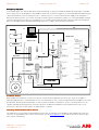
The minimum wiring configuration between drive and motion controller requires 24V connected to the MicroFlex e100 drive enable
input. This enable signal can be wired via safety interlocks as require. This input is not a safe torque off input – users should ensure
that safety risks are assessed and the design of the safety critical elements of the control system is suitable (e.g. it may be
necessary to include motor contactors between the e100 drive and the BSM servo motor). Further wiring details are available in the
MicroFlex e100 Installation Manual MN1942.
Recommended I/O connections
Three digital inputs on the MicroFlex e100 are provide to allow connection of signals such as home sensor and limit switches. Two
of these (Inputs 1 and 2) can be used for high speed registration, capturing position in the order of nS to µS (depending on
feedback type). An additional input provides a hardware enable interlock. Two digital outputs can be configured for functions such
as motor brake control and drive ready.
Drive enable signal:
Each MicroFlex e100 drive needs to have a 24V signal applied to its enable input. This should not be wired from an output on the
NextMove e100 controller (only local axes require the connection of an output on the Nextmove e100). It may be a good idea to
wire the enable signal through a safety relay associated with a guard switch or Emergency Stop circuit (as well as including other
safety measures, such as motor contactors, depending on the level of risk associated with the control system).
Home input:
The MicroFlex e100 and MotiFlex e100 differ from other drives in that the homing switch must be wired back to one of the drive’s
digital inputs. The reason for this is that e100 drives perform the home sequences themselves (to ensure maximum accuracy). If the
NextMove e100 tried to track the axis position during homing there would be an error introduced due to delays in the EPL network..
Most of the Mint commands associated with homing are saved as parameters settings on board the e100drive. These settings can
be changed from the NextMove e100 if required using a technique called “re-direction” which is explained later in the section on
homing.
Fast latching inputs:
Triggering a position capture on an input needs to be able to respond in the order of µS. EPL network delays preclude using the
NextMove e100 to capture the position of remote axes. As a result, fast latching triggers must be wired to the MicroFlex e100. Most
of the Mint commands associated with fast latching are saved as parameters settings on board the drive. They can be changed
from the NextMove e100 using re-direction.
Motor brake control output:
The MicroFlex e100 has 2 digital outputs that can be used to control a motor brake. Most of the Mint commands associated with
brake control are now saved as parameters settings on board the drive. They can be changed from the NextMove e100 using redirection.
ABB Motion control products
www.abbmotion.com
2
Application note
Getting started with e100
AN00187-002
Emergency stop input:
As described earlier, each drive enable signal can be wired through a safety relay if required. Additionally an Emergency stop input
from a safety relay can be wired back to the NextMove e100. This can then be assigned as an axis STOPINPUT in the Mint program
onboard the Nextmove e100. E-stop logic may also control the state of a contactor either in the AC supply to the e100 drive or
between the drive and motor. It is common to provide an instant signal to the Nextmove e100 (to act as the STOPINPUT) and delay
removal of drive and/or motor power (so the Nextmove can command an immediate powered stop before finally removing power)
but the actual implementation must be determined by the user according to the result of risk assessment.
EPL
PC
USB
Filter
NextMove e100
MicroFlex e100
24Vdc
Contactor
Mains
Estop
logic
USB
Motor Power
Stop Input
Drive Enable
Motor Feedback
24Vdc PSU
24V Logic Supply
Connection Overview
Feedback devices
Motor feedback is essential for accurate “closed loop” control for both the Speed and Position loops. There are a number of
different feedback devices commonly fitted to motors. For a brushless AC servo system it is important that the feedback to the drive
provides both absolute positional information as well as speed. The positional information is used to commutate the motor. The
speed is derived by measuring the rate of change of position. The MicroFlex e100 drives have a built in position loop. It is not
hnecessary to pass the encoder signal to an external motion controller.
Switching c ommunication between devices
This application note was written using Workbench Version 5624. The firmware on the NextMove e100 and MicroFlex e100 was
5615. It is recommended that this or more recent firmware is used (www.abbmotion.com provides downloads for the most up-todate software and firmware).
ABB Motion control products
www.abbmotion.com
3
Application note
Getting started with e100
AN00187-002
During the configuration of the MicroFlex e100 and the NextMove e100 it will be necessary to switch the communications link
between the devices. The USB cable will need to be moved back and forth between the NextMove e100 and each drive. This is
referred to as a single port setup. Alternatively two copies of Mint Workbench can be used simultaneously provided the NextMove
e100 and the MicroFlex e100s have different USB port addresses. Changing the USB port address is explained below.
If this is the first time you have used Workbench you may be prompted to install a USB driver when you first connect to the drive
(depending on which version of Workbench you are using – later versions install the necessary device driver automatically).
Connecting to a MicroFlex e100
−
−
−
−
−
−
−
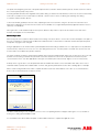
The EPL address should be set via the rotary hexadecimal switches on
the front of the MicroFlex e100. These can be set to anything in the range
01 to EF but it is typical to start the addressing from 03 and work
upwards as more axes are added. This allows Node/Axis/Encoder to
match (as encoders 0 to 2 are always local to the Nextmove e100). Set
the switches before the drive is powered up
Make sure the MicroFlex e100 has 230 VAC and 24 VDC applied
Connect to the MicroFlex e100 via the USB cable
Run Mint WorkBench
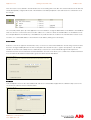
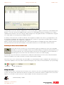
Workbench should detect the drive automatically and connection details
will appear in the list. If this does not happen click the Scan button.
Make sure the Launch Commissioning Wizard box is checked. The
Launch Commissioning Wizard box only needs to be checked when the
drive is first setup.
Click Select to connect to the MicroFlex e100.
MicroFlex e100 c ommissioning
Welcome page
If the commissioning wizard does not automatically start it can be selected by choosing Tools->Commissioning from the Menu.
The Commissioning Wizard shows a sequence of screens displaying the current drive settings and requesting information required
to commission the drive. When each page is complete click the Next button to continue through the Wizard.
The first screen describes the process and offers the opportunity to set all drive parameters to their factory default setting. Make
sure the Reset to Factory Defaults box is checked and click the Next button.
ABB Motion control products
www.abbmotion.com
4
Application note
Getting started with e100
AN00187-002
Note: The reset to factory defaults is clicked here because we are starting with a new drive. This should not be done if the drive has
already been partially configured. At the end of the wizard the user will be prompted to “Save and Reset” the controller OR cancel
the changes.
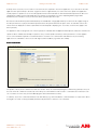
Connectivity
The connectivity wizard opens up. In this application note we would like to change the USB address to be different to the NextMove
e100. It is set here to 3 which is the same as the EPL address. It is common to either set the USB address of all e100 drives to be
the same (but different to the Nextmove) so the USB lead can just be moved from one drive to the next without the need to rescan
for a drive, or to set the USB address to match the EPL node address (making each node unique).
Select motor
Select the correct motor type from “AC brushless rotary” or “Linear” etc and click the Next button. The following screen then allows
the motor catalogue number printed on the motor name plate to be selected. Be sure to copy the exact product code. The Spec
number can also be used to identify the motor. Alternatively a custom motor can be entered although this will require more
information from the motor manufacturer. Click the Next button. The next screen allows you to confirm motor and drive information.
You can review the information here but need to go back to edit it. Click the Next button.
Feedback
In this example the motor has Encoder feedback with hall sensors. Other feedback types will have a different setup screen to the
one shown. Encoder motors have a fixed resolution.
ABB Motion control products
www.abbmotion.com
5
Application note
Getting started with e100
AN00187-002
Operating mode
Unlike analog MicroFlex drives, the MicroFlex e100 has a position loop onboard the drive. Since we will be testing basic positioning
moves in this application you should select “Position” for the control mode. The reference source should be selected to EPL as the
drive will be receiving its position reference from the NextMove e100 over EPL.
Application limits
The Application Peak Current cannot be higher than either the motor peak current or the drive peak current. If the setting is too low
the drive will not run to speed as it won’t be able to provide enough torque.
The motor overload response can also be set here. By default the drive will trip on an over-current condition. Sometimes it may be
desirable to limit the torque by folding back the current.
ABB Motion control products
www.abbmotion.com
6
Application note
Getting started with e100
AN00187-002
At this point it is necessary to have a feel for how fast the motor is required to move in the application. If you don’t know what the
application max speed is likely to be at this stage then set this to approximately 75% of the max motor speed. If the application
actually requires a speed in excess of the value typed here then it will not be able to attain the demanded speed and a drive overspeed trip error will be created. If the application max speed is changed later (e.g. via the “Operating Mode” pages within
Workbench) then it will be necessary to retune the drive’s speed and position loops.
Be aware that the maximum speed is limited both by the available bus voltage (approximately 1.41 times the AC supply voltage to
the drive) and the motor’s physical maximum speed, therefore the speed entered at this point cannot exceed either of these two
values which are displayed for reference (if the Max Theoretical Speed is displaying 0 or a low value, check the AC supply to the
drive is present).
For applications that are designed to run at slower speeds it is advisable that the Application Max Speed is reduced to maximise the
speed resolution available, this will improve speed accuracy at lower speeds. But always set this parameter to a value slightly in
excess of the maximum required to avoid unwanted errors. It is best not to set this below 500 RPM. For very slow running
applications it is advisable to select a motor with high resolution feedback (e.g. Endat, SSI or BISS).
Select scale factor
The position, velocity and acceleration user units are set here. These are used mainly during the commissioning wizard (i.e. they set
the user unit for all commands issued locally on the drive). Once the Nextmove e100 is used to command motion it will use its own
set of scalefactors for this axis (set via the Mint program onboard the Nextmove e100).
In summary, any motion commands initiated on the drive directly (e.g. via the Workbench command window or as part of the drive’s
homing process which is always profiled by the drive itself) will use the scalefactors set on the drive.
ABB Motion control products
www.abbmotion.com
7
Application note
Getting started with e100
AN00187-002
Profile parameters
The MicroFlex e100 is referred to as the “Controlled Node”, or CN, and the NextMove e100 is referred to as the “Manager Node” or
MN. During Manager Node (MN) profiling the manager node (the Nextmove e100) profiles moves on behalf of the controlled node,
sending continuously updated incremental demands to the drive. As a CN axis the drive receives a single position command from
the NextMove e100 and the drive profiles the move itself. Further information on this topic can be found in the help file entry
Contents->Fieldbus Networks->Ethernet Powerlink->DS402 modes of operation.
The current, speed and position profile parameters shown above are used by the drive when it is set up for “Control led Node (CN)
Profiling” but are also used as defaults for Fine tuning test moves. Later during the NextMove e100 setup the drive will be setup for
“Manager Node profiling” so these settings are not critical.
The Position Control parameters must be set regardless of whether the drive is MN or CN profiled. All of these parameters are
scaled according to the scalefactors that were set earlier:
Max Position Error – this sets the maximum deviation allowed between demand and measured position at any time (i.e. following
error limit)
Idle Position Tolerance – how close the axis must be to the target position to consider a move to be complete (i.e. axis to be IDLE)
Idle Velocity – the speed below which the axis must be travelling in order to consider a move to be complete (i.e. IDLEVEL). The
minimum speed resolution is 4000 counts/sec so it is typical to set a value equivalent to 160000-20000 counts/sec (the value used
depends on the VELSCALEFACTOR set earlier).
Select “Finish” to move on to the Autotuning section. See below.
Tuning the MicroFlex e100
The drive contains 3 nested control loops. The innermost loop is the current control loop. This is enclosed within the speed control
loop. The outermost loop is the position control loop.
The current loop receives a torque demand from the speed control loop. The current loop then drives current into the motor which
creates torque causing it to accelerate or decelerate.
The speed control loop receives a speed demand from the position control loop. The speed control loop is important as it provides
a good dynamic response, a reduced risk of erratic behaviour and makes the position loop far easier to tune for the majority of
cases.
ABB Motion control products
www.abbmotion.com
8
Application note
Getting started with e100
AN00187-002
The Position and Speed control loops are closed control loops which require feedback from the motor. A transducer fitted to the
motor generates a signal which is used to determine the actual position and speed of the motor. Any difference between this and
the demanded position and speed causes a demand on the current controller which in turn causes the motor to react to close the
gap. Each of these control loops has some associated gain terms, each of which require tuning to the system load conditions.
Before the tuning process can be started it is necessary to ensure that any brake fitted to the motor is released and an enable input
is provided to the MicroFlex e100.
If a brake is fitted to the motor make sure 24V is applied and check that the motor shaft is free to turn. Motor brake control is now
available locally on the MicroFlex e100 and MotiFlex e100 drives. See the section below entitled “Viewing and changing parameters”
for information on how to change the motor brake control parameters.
This application note is written under the assumption that the motor is being tested on a bench or at least under a light
load. If there is a load suspended vertically from the motor and the brake is disengaged while the drive is disabled then the
load will fall without any inhibition.
When setting up the MicroFlex e100 the drive has to be operated in Direct mode. This means that the “Control Reference Source” is
Workbench over USB rather than the NextMove e100 over EPL.
Select the “Control Reference Source” on the toolbar on the top of the page. In the popup box select “Direct (Host/Mint)”.
Workbench is the host in this case. If the drive was a MotiFlex e100 with a Mint option card then the drive would be Mint controlled
during operation. You would select the Control Ref as Direct in that case as well.
Autotuning
To begin with it is always advisable to AutoTune the system with the motor disconnected from the load. This ensures that
the system is functioning correctly before moving the load and reduces the risk of causing damage. This application note
assumes the motor is unloaded and free to rotate in either direction.
If you are using a standard Baldor motor selected from the database and the wiring is correct, it should only be necessary to
complete the recommended Autotuning steps:- Calculate current loop gains, Measure the motor inertia, Calculate the speed and
position gains.
ABB Motion control products
www.abbmotion.com
9
Application note
−
−
Getting started with e100
AN00187-002
Select the desired Autotuning options by clicking the tick boxes.
Click the START button to proceed.
If Autotuning fails, selecting the other tuning options may correct some simple wiring or configuration faults. In particular you should
select “Test the feedback” (note that if the motor or feedback is wired incorrectly this test may autocorrect for this and the resulting
parameters will then only suit equally “miswired” motors in future).
If the errors continue to be generated check the wiring carefully and refer to the help files for more assistance on Autotuning errors.
If the feedback is OK but autotune fails on the Motor Inertia measurement test this might be because there is not enough torque
delivered during the test to move the motor. Select “Options” and then choose the “Limits” tab. Increase the percentage “Max
Torque”.
If the test fails when performed offload then this error would signify a wiring fault or a locked rotor shaft.
If all tests complete successfully but the motor response is poor or noisy try adjusting the speed/position loop bandwidth on the
‘Bandwidth’ tab of the Options dialog and repeat the tests.
ABB Motion control products
www.abbmotion.com
10
Application note
Getting started with e100
AN00187-002
Fine tuning the current loop
The MicroFlex e100 current loop should be tuned quite well during the auto tune so you wouldn’t normally have to look at this. If the
motor is large then it is worth checking the current loop.
The test parameters can be left for a stationary type move with the current at 25% for 50ms. Press Go to start a test move. The
motor will jerk slightly and the current data will be uploaded to workbench.
Turn OFF the graphs for “Magnetising Voltage Demand” and DC Bus Voltage”. The graph will then re-scale to show the “Measured
and Demand Magnetising Current” as above.
Increasing KITRACK can sharpen the response of the measured current. If the measured current tends to overshoot the demand at
the start and end of the move then KITRACK may be set too high.
Fine tuning the speed loop
We will now perform a test speed move. Make sure the Velocity tab at the bottom right corner of the WorkBench screen is selected.
ABB Motion control products
www.abbmotion.com
11
Application note
Getting started with e100
AN00187-002
This example test move is set up to do a bi-directional move at 20Rev/s for 5 Revs. Click the Go button when these parameters
have been typed in and you are ready to start the move. When the move is complete and the graph is displayed look at the Speed
Measured and the Speed Command Demand, hopefully these will show a reasonable match. Try to use acceleration, deceleration
and speed values that will be “typical” for your application.
The gain values can be calculated automatically by Selecting “Calculate...” and adjusting the Bandwidth. The higher the Bandwidth
is, the higher the gain values will be. This will make the motors response to speed changes stiffer. If the Bandwidth is too high the
motor may overshoot on reaching the target speed and may become excessively noisy/unstable.
A small amount of overshoot on the speed response is acceptable. If there is a large overshoot it can be easily reduced by
decreasing the value of Tracking Factor (KVTRACK) and trying the move again.
If the motor is particularly noisy and/or there is a lot of vibration at steady/zero speed try manually reducing the value of KVPROP.
The graph above shows a typical response to a bidirectional move. The Demand Speed (Blue) and measured speed (Green) should
closely match. Increasing KVPROP increases the damping effect on the oscillations during steady speed. Increasing KVINT
improves the sharpness of the response during acceleration and deceleration
If the motor is going in the wrong direction (i.e. for a positive speed demand it needs to go in the opposite direction) it can be set by
changing the MOTORDIRECTION parameter in the MicroFlex e100. See the section further on entitled “Viewing and changing
parameters” for more information on this.
Once the velocity loop is tuned the drive is ready to have its position loop tuned.
Fine tuning the position loop
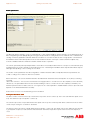
Select the Position tab within the Fine tuning work area.
The position loop gain values can be calculated automatically by Selecting “Calculate...” and adjusting the
Bandwidth. The higher the Bandwidth is the higher the gain values will be. This will make the motors
response to speed changes stiffer (note that changing the position loop gains via the Calculate button this
way will also automatically result in the speed loop gains being recalculated and vice-versa).
The Autotune will calculate values for KPROP and KVELFF (even on-load). The value of KPROP
(Proportional Gain) may also be determined experimentally. This means you need a starting point, a value
of 0.01 is appropriate as a starting point for most systems.
To test the position loop gain values you need to define a suitable test move. Provided your motor is still
unloaded it should be safe to make a move, a profile lasting about 1s is ideal. It is also best to choose
accelerations and speeds that define a trapezoidal profile shape. In the Fine-tuning screen on the Position
tab type in the following values which are suitable if scaled in Revs:
ABB Motion control products
www.abbmotion.com
12
Application note
Getting started with e100
AN00187-002
Speed = 30 (rev/s)
Acceltime = 100 (ms)
Deceltime = 100 (ms)
Distance = 30 (revs)
These values give a move time of 1.1s. Make sure the KPROP and KVELFF values have been typed in correctly and click the GO
button. The motor will perform the move and the captured data will be uploaded and displayed on the screen. If the motor vibrates
excessively then the starting value for KPROP could be too high; this is more likely with high resolution systems.
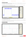
In the diagram above the trapezoidal shaped line (in green) is the measured velocity trace and the “S” curve (blue) line is the
measured position. It is also possible to turn on and off the Demanded Velocity and the Demanded Position, the objective of tuning
is to get the measured line to follow the demanded line as closely as possible.
To fine-tune the position loop gain terms it is best to look at the difference between the measured position and the demanded
position, known as the following error. To see this on your graph make sure all other plots are turned off by un-checking the check
boxes. Alternatively you could assign a new y axis on the graph to the same scale as the following error.
.This is a typical plot of following error for a trapezoidal move.
ABB Motion control products
www.abbmotion.com
13
Application note
Getting started with e100
AN00187-002
The peaks at the beginning and ends of the profile represent the acceleration and deceleration periods. The flat area in the centre is
the constant speed (steady state) section.
Increasing KPROP will reduce the magnitude of the peaks during acceleration and deceleration, however an excessive value is likely
to introduce oscillations in the overall response. KACCEL can be used as a means of reducing the following error during
acceleration and deceleration phases.
To fine-tune KPROP gradually increase its value, repeating the test move each time, using it to decrease the overall error and
improve the settling time of the axis at the end of the move. If KVPROP is too high it will be particularly apparent when the motor is
stationary as it will vibrate.
Other gain terms can be added to improve the response, but this is beyond the scope of this document. Please refer to the
manuals and help files for more information.
Connecting a load
When every part of the system has been tested and is working correctly it is time to connect the load. This will require some parts of
the servo system be re-commissioned. The MicroFlex e100 will need to re-measure the load inertia and this will require the speed
and position loop gains to be changed.
Using an appropriate accel and decel time is particularly beneficial when tuning loaded motors as a step response is very difficult to
achieve. Be very careful not to move too far or too fast during the test moves. It is always best to start with slow short moves and
increase until a reasonable motion profile is attained.
The value of KVELFF should not change, but the KPROP may need to be modified. Again make sure any test moves do not exceed
the limits of travel. Using scaled units may make this easier. Recalculate the scale factor to represent the mechanical system
connected to the motor, use units appropriate to the type of movement (mm for linear travel, degrees or revs for rotary travel).
At this point it is a good idea to save the parameter file from the MicroFlex e100. Connect to the MicroFlex e100, select Tools >
Parameter Table > Upload, find a suitable folder on the PC and give the parameter file a name “Axis 3 Settings.ptx” for example.
When commissioning the MicroFlex e100 is complete the drive needs to be switched back over to EPL as a Control Reference
Source. This is selected from the Tool bar as shown.
The drive commissioning is now complete. You have a choice of repeating the drive setup procedure again on a second drive or
moving on to setting up the NextMove e100.
It is assumed that two drives will be setup but one drive will be sufficient to complete the application note
ABB Motion control products
www.abbmotion.com
14
Application note
Getting started with e100
AN00187-002
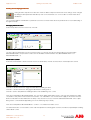
Viewing and changing parameters
During the drive setup the motor direction and motor brake setup were mentioned. These settings can be changed
by editing the drive parameter table directly. Click on the Parameters icon on the toolbox on the left hand side of
Workbench.
The screen that appears is divided into a parameter search tree on the left hand side and a parameter list for each subheading on
the right hand side.
Changing motor direction
direction
Select Family->Motor from the search tree on the left.
The motor direction parameter is the 2nd one listed. Click on “Forward” and select the desired direction from the listbox.
MOTORDIRECTION is a keyword that can be set in the Workbench terminal window also (MOTORDIRECTION = 0 or
MOTORDIRECTION = 1)
Motor brake control
Select Axis/Channel/Bank-> Brake Channel. Three motor brake delay channels are listed. Each channel represents a timer.
Channel 0 is the time allowed to engage the brake before disabling the drive.
Channel 1 is the time allowed to disengage the brake before starting motion.
Channel 2 sets the delay between enabling the drive and it establishing servo control.
Now select Family>Motor>MotorBrakeOutput – this sets which digital output will be used to control the motor brake (this output
should drive a relay which in turn feeds the motor brake – also remember to use an isolated 24V supply for the feed to the motor
brake as indicated in the User Manual for the drive). It may also be necessary to invert the OUTPUTACTIVELEVEL of the output
being used to control the brake (depending on how the interfacing relay is wired).
Now select Family>Motor>MotorBrakeMode – set this to 1 to enable motor brake control
For further information on motor brake control read the help file in the following path: Contents->Hardware->Input/Output Handling>Motor brake control.
ABB Motion control products
www.abbmotion.com
15
Application note
Getting started with e100
AN00187-002
The parameter table will automatically save to the drive when a parameter is edited. To save parameter files on your PC (as a
backup) choose…
Tools->Parameter Table->Upload.
Adding drives to the NextMove
NextMove e100 EPL network
Connecting to NextMove e100
Make sure there is 24V power applied to the NextMove e100.
−
−
−
−
−
Connect a USB cable to the NextMove e100
Run Mint WorkBench
Select Start New Project
Mint Workbench should detect the NextMove e100 automatically and the connection details will appear in the list. If this does
not happen Click the Scan button.
Select the NextMove e100 when it appears in the list
Note: Mint WorkBench project files contain information about your application, including:
−
−
−
Information about the controller that is currently connected.
Links to the program file (.mnt
.mnt file). But NOT the actual program file.
Other desktop details.
The project file does not contain any program code - it is contained in the separate .mnt file. Always remember to “Save File” after
making any program changes.
It is important that there is no program in the NextMove e100 when configuring, as settings from a different system may cause
unexpected behaviour. To delete a program, select the menu option Program > Delete Existing.
Connectivity
Select the Connectivity icon on the Workbench tool bar on the left hand side. As shown above, this will open up a dialogue
providing access to all the communication settings.
ABB Motion control products
www.abbmotion.com
16
Application note
Getting started with e100
AN00187-002
The NextMove e100’s node address can be set for each of the networks it is connected to. The Ethernet address needs to be set
via the rotary hexadecimal switches on the front. The Ethernet address should be set to F0 (240 decimal) if the Nexmove e100 is to
be used as a Manager node on an EPL network (as in the case of this application note).
It is a good idea to set the USB address here to be different to the address on any of the MicroFlex e100 or MotiFlex e100 drives
being commissioned as explained earlier.
System Configuration
Before we can control an e100 drive from the Nextmove e100 we need to configure the EPL network (i.e.
configure the Nextmove so it is aware of what devices may be present on the network). Select the System
Configuration icon on the Workbench tool bar on the left hand side. This will open up the wizard shown below.
This screen gives you a choice of uploading the current configuration from the controller, opening an existing configuration file or
starting a new configuration. We will start a new configuration in this example. Click on “Next”.
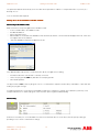
The devices and drives that are connected to the NextMove e100 via EPL are listed in a table. When setting up for the first time this
list will initially be blank. For now leave the Cycle Time set to 2ms (this is adequate for most applications). Click on “Add Device...”.
ABB Motion control products
www.abbmotion.com
17
Application note
Getting started with e100
Choose MicroFlex e100 here as the device type.
The MicroFlex e100 node ID was set to 3 when the drive was setup
so set it to 3 here.
Note that other, non Baldor, device types can be added here. You
would select “Import Device” to do so although we won’t be doing
this in this application note.
Click on “OK when everything is selected. The Resource Mapping
screen will follow.
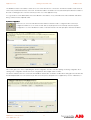
Each device on EPL comes with many attributes or resources. These can be mapped
to the NextMove e100 on this screen.
Initially nothing is mapped (as indicated by the red crosses). The NextMove e100
reserves encoder channels 0,1 and 2 for its local encoder inputs so it is a good idea
to start the remote axis numbers from 3 onwards to avoid a conflict with local
encoders 0 to 2.
Double click on Axes->Axis 0 to map the drive as a controllable axis.
After clicking on Axes->Axis 0 on the Resource Mapping screen this popup shows
up. Set the Axis number as required (3 in this example).
We described the drive profiling options earlier (see the sub section on “Drive Profile
Parameters”). As we’re going to profile motion from our Nextmove e100 we’ll select
“Manager node Profiled”.
If you need to utilize a latched axis position in the Nextmove’s Mint program (e.g. for
registration applications) you can map a MicroFlex e100 latch channel to a NextMove
e100 latch channel (allowing the fast capture position to be transferred to the
Nextmove). Latching over EPL is beyond the scope of this application note. It is
explained in more detail in application note “AN00177 Cut to registration”.
Click on OK. The resource mapping dialog will now show that we have mapped the
drive back to the Nextmove (i.e. a green tick is displayed). The drive itself considers
its own axis to be axis0, but as far as the Nextmove is concerned it is axis 3.
ABB Motion control products
www.abbmotion.com
18
AN00187-002
Application note
Getting started with e100
AN00187-002
Because the MicroFlex e100 is on an EPL network it is possible to read
and write many of the parameters in the drive every cycle of the EPL
network (every 2ms for the configuration we’ve made so far). There may
not be enough bandwidth to use them all. This depends on the cycle
time and the number of axes on the network. It is best to select only
those actually required.
This setup procedure will automatically map the essential drive attributes for control of a remote axis. You don’t need to add any but
in this example, we will, so that you know how it is done. There are two ways data can be passed:
Controlled Node <- Manager Node : this is data sent from the Nextmove to the drive
Manager Node -> Controlled Node : this is data sent from the drive to the Nextmove
“AXISMODE” is an example of a useful keyword that we can map from the drive back to the Nextmove – e.g. so the Mint program
can use the value of this in the application (CURRENTMEAS and FOLERROR are other useful items). Double click or expand the
Process Data (Controlled Node->Manager Node tree and select Axismode in the tick box. As process data is mapped the PDO
Item count will start to grow towards its maximum limit.
TORQUELIMITPOS and TORQUELIMITNEG would be examples of items we might add as PDO mappings from the Nextmove to
the drive (e.g. to set torque limits in a tensioning or winding application).
The axis position is automatically mapped, but it is also possible to add a mapping
for encoder.
After clicking on Encoders->Encoder 0 on the Resource Mapping screen the dialog
to the right appears.
Map the MicroFlex e100’s encoder value to “Encoder 3” on the manager node (i.e.
the NextMove e100). This way everything about this drive is consistent (i.e. the
node address, axis number and encoder value are all set to 3). The encoder
resolution should always be set to 24 bits.
Once all these mappings have been completed, close the Resource Mapping
Dialogue and click Next.
The remote axis list reappears and now shows the remote e100 axis that we just configured. It is at this point that you can add
another axis if you have more than one MicroFlex e100. The procedure just outlined would then be repeated.
When all the axes have been configured click Next.
ABB Motion control products
www.abbmotion.com
19
Application note
Getting started with e100
AN00187-002
The dialog above shows two e100 axes added to EPL. Local axes (analog drives, steppers or virtual axes) can be added from this
dialog too. Local servo axes are not mapped over EPL. They use one of the NextMove e100’s Encoder inputs 0,1 or 2 and the
speed demand to the drive is sent via an analogue output (we might use an analog MicroFlex drive or an ACSM1 drive configured
for +/-10Vdc input as local analog axes for example). Click Next.
A summary screen follows this one. After the summary is the Configuration Complete screen. Here is a good opportunity to save
the .dcf (Device Configuration File). Click “Finish” to download to the controller. It is a good idea to include the option to reset the
controller after the download. This completes the configuration.
After the controller resets the bottom right hand LED on all the networked devices should light (and remain solidly lit rather than
flash). This indicates that the network has initialised correctly and that the device is an active member of the EPL network.
Performing test moves from the NextMove e100
Check that all of the connections are correct and that the signals are working in the correct sense. Using Mint
WorkBench connected to the NextMove e100, select the Edit & Debug icon and type the following instructions at
the Command window. This is in the bottom right of the lower area of the Workbench screen, by default with a
black background. You need to click in this area first to move the focus to it before typing.
We are ready to try to move the motor, ensure there are no obstructions and that the motor is free to turn, either with the brake
released or with brake control setup on the drive so it releases when the drive is enabled.
If the motor moves out of control be ready to click the Enable icon on the WorkBench toolbar to disable the drive. Alternatively you
can push the stop button on the axis toolbar or operate the Emergency stop circuit if you have included this in your system design.
Stop button
Enable / Disable button
Setting scale factor.
To define motion in terms of useful user units it is normal to set a scale factor. The scale is calculated by determining the number of
encoder counts per user unit. Useful units may be motor revolutions (revs) or linear mm of travel for example. In this case our units
will be revs so we need to set the scale factor to suit the number of encoder counts per motor revolution.
SCALEFACTOR(3) = 10000
ABB Motion control products
www.abbmotion.com
20
Application note
Getting started with e100
AN00187-002
Note
Mint has an abbreviation for most of the keywords which is useful when typing at the command line as it reduces the amount of
typing required. A few are listed below
MOVER = MR
SCALEFACTOR = SF
PRINT = ?
DRIVEENABLE = DE
These commands, and others, are all described in more detail in the Mint Help files. Context sensitive Help can be obtained by
pressing F1 with the cursor positioned on a Mint keyword in the command line.
The use of abbreviated commands is not recommended for use in a program, it makes the code very difficult to understand at a
later point in time or by other people.
Trapezoidal moves.
The scale factor should now be set so that a user unit of 1 corresponds to 1 rev. Now it’s time to perform a few test moves. Type
the following on the command prompt.
POS(3) = 0
DRIVEENABLE(3) = 1
SPEED(3) = 5
ACCEL(3) = 20
DECEL(3) = 20
MOVEA(3) = 5
GO(3)
MOVER(3) = 4 : GO(3)
MOVEA(3) = 0 : GO(3)
Set the absolute position to zero.
Enable the drive.
Set the target speed of the move to 5 revs/s
Set the move acceleration rate to 20 Revs/s2
Set the move deceleration rate to 20 Revs/s2
Perform an absolute move to position 5
Start the move with the GO command
Perform a relative move a further 4 units forward.
Note that commands can be cascaded on one line with a colon.
Perform an absolute move back to position 0.
Initializing the EPL network using Mint
The EPL network is configured in Mint WorkBench using the System Configuration Wizard. When the Mint code running on the
NextMove e100 starts up it is a good idea to run some code at the start of the program to determine when both the EPL network
and the remote devices are operational. This code is normally called from the NextMove e100 Mint Startup module.
The recommended initialization sequence is as follows:
1.
2.
3.
4.
5.
6.
Check that the Ethernet network is operational or cyclic.
Check that all nodes are live.
Check that each node is capable of exchanging a Service Data Object or SDO.
Check that each node is capable of exchanging a Process Data Object or PDO.
Check that the drive is in an operational state as defined by the DS402 protocol.
Finally check to see if the drive is in remote mode.
The full implementation of this code is explained in detail in the Workbench help file in the following path: Contents->Fieldbus
Networks -> Ethernet Powerlink -> Initializing the EPL network using Mint.
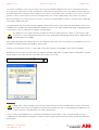
So now we need to create our Mint program. From the toolbox click on the Edit and Debug icon down to the left.
From the file menu choose New File. This is not to be confused with the project file that you are already viewing. Remember, the
Mint code file is not contained in the project file, the project file just remembers that you were editing this Mint file.
ABB Motion control products
www.abbmotion.com
21
Application note
Getting started with e100
AN00187-002
The new program file will be blank when it is first opened.
Rather than writing all of the EPL initialisation code from the beginning, Workbench comes with some standard
code snippets/examples which include the EPL initialisation code. This EPL initialisation code snippet can be
used in the start-up block.
On the lower left hand side of the program window is the Mint library. When you first use
Mint Workbench this window will either be blank or may already show the pre-loaded
examples (depending on Workbench version installed).
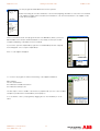
If you need to open the samples library, right click on the Mint library window. A popup
menu will appear. Choose “Open sample library”.
A list of code snippets will appear.
To construct our program we will use the following code snippets listed below:
Mint Template
Function doInitialiseEPL
EPL Initialisation Variable Declarations
EPL Initialisation Startup code
The first step is to have a suitable code structure to populate with your own code. The Mint
Template is provided in the standard library for this purpose.
You can add the code to your program by dragging the icon from the library on to the
editor.
ABB Motion control products
www.abbmotion.com
22
Application note
Getting started with e100
AN00187-002
Alternatively, if you want to see a preview of the code first, open up the code by
double clicking on the entry in the library. The code preview dialog opens up.
Right click on the code and select it. It can then be copied.
Alternatively highlight the code by clicking in the window at the top and using the
shift and arrow OR page down keys. Note that Ctrl-A doesn’t work to select all
text in this window. Copy the code using Ctrl-C and paste it into the program
window using Ctrl-V
In the template program there is a line in the startup block…
‘Auto
…remove the ‘ (the comment) if you want the program to automatically run every time the Nextmove is powered up (recommended
for most applications).
The next step in writing a program should be to update the program startup block with the
current parameter settings for the axes we are using. The program startup block is executed
first every time the Mint program is started. This is the best place to set parameters such as
scale factors etc… which are not likely to change during running.
From the Program menu choose “Generate Mint Startup Block”. This will populate the Startup
block with the current settings. Note that this action will overwrite any existing code that is
present between the two comment markers in the startup block. You will see a warning dialog
to this effect before you can proceed.
Once the Startup block has been written the next step is to copy in the code for initializing the EPL network. Select “Function
doInitialiseEPL” from the Mint library and drag it into the new template code under the “Global Function” heading as shown here:
'--------------------------------------------------------------------' Global Functions
'---------------------------------------------------------------------
Drag in Function doInitialiseEPL here
Now select the “EPL Initialization Variable Declarations” and “EPL Initialisation Startup code” samples from the Mint library and drag
each of them into the program below the startup block heading as shown:
Startup
'Remove comment from auto instruction if program needs to run
'automatically on power up...
Auto
' Add user startup code here...
Dim nEthernetNodes(3) As Integer = {2,3,4}
Dim nEthernetAxes(3) As Integer = {3,4,5}
Dim nEPLState As Integer
Repeat
nEPLState = doInitialiseEPL(nEthernetNodes,nEthernetAxes)
Until nEPLState = _true
ABB Motion control products
www.abbmotion.com
23
Application note
Getting started with e100
AN00187-002
Note that the code sample assumes that there are 3 EPL nodes and dimensions the nEthernetNodes and nEthernetAxes arrays
accordingly. In our example if two drives were setup as nodes then these arrays should have dimension 2. The nodes and axis
numbers should also both be changed to match the Device Configuration File we set up earlier on the controller.
Dim nEthernetNode(2) As Integer = {3,4}
Dim nEthernetAxes(2) As Integer = {3,4}
Congratulations ! You now have a program which will perform the initial checks on the EPL network before executing the main
code. Download and Run this program (Click on the green triangle button or select Program>Compile, Download and Run)….if
you’ve not made any mistakes the program should run and the Workbench terminal window should report that EPL is initialized.
The test moves performed in the previous section can also be written as lines of code in a Mint program. Describing how to
program in Mint is beyond the scope of this application note. To find out more about Mint programming in general see the Help file
section:
Contents->Mint basic programming.
Homing e100 series drives and controllers
The MicroFlex e100 and MotiFlex e100 drives control homing locally on the drive. Therefor all home related parameters (home input,
home speed, home accel etc…) must be configured on the drive.
Go online to the MicroFlex e100
Select Digital I/O in the tools bar on the left hand side.
Drag IN0 onto Home to make digital input 0 the home sensor input on the drive (or use whichever input you’d like for the
application).
ABB Motion control products
www.abbmotion.com
24
Application note
Getting started with e100
AN00187-002
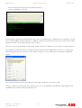
Click on ‘Parameters’ in Mint Workbench’s toolbar and select Homing from the parameter family tree on the left hand side. The
right hand pane will now display a list of all the homing parameters for the axis as shown below:
This section allows all drive parameters associated with homing to be set locally on the drive. The homing type selected here is 0
which corresponds to “Home negative switch” (see the Mint help file for the enumeration of homing types). You could select the
drive to home in a negative direction to the index pulse if there is no switch at hand (Hometype of 4). It doesn’t really matter what
you enter in the parameters for Hometype though as this is modified at runtime when the HOME command is issued. If you have a
switch it is better for testing as you can choose when to toggle the switch which makes it easier to see what is happening. Once
entered these parameters are stored in the drive’s parameter table. The home sequence can be tested by entering the required
command at the Workbench command window.
HOME(0) = 0
Or use the Mint constants….e.g. HOME(0) = _hmNEGATIVE_SWITCH
Note
All the scaled values (HOMESPEED, HOMEACCEL etc…) are based on the scalefactor on the MicroFlex e100. #
The drive uses its local scalefactor when homing. This may be different to the scalefactor on the NextMove e100
but it is typical to set the same scalefactor on both. Although we entered a home type on the drive, it is actually
the Nextmove e100 that commands which type of home sequence to perform….the drive is just responsible for
performing this process.
Go online to the NextMove e100
On the command line for the NextMove e100 type Home(axis) = 1 (replace axis with the axis number for the drive you’re testing) .
The number ‘1’ signifies _hmNEGATIVE_SWITCH_INDEX which is the homing type (refer to HOME in the Mint help file for a full list
of homing types available and their associated Mint constants). The MicroFlex e100 should perform a homing move back until the
home switch is detected on DIN0 (or whichever input you selected). It then moves forward again more slowly until it moves off the
switch.
Homing parameters can be set in the drive during the drive setup (as shown above or by directly editing the drive parameter table).
You might however want to set these parameters up from the program in the NextMove e100 to allow greater flexibility and/or to
provide more “visibility” on the setup of the drive. To do this you can use a program technique called “redirection” which allows you
to read and write parameters over EPL. Redirection is explained in more detail in the help file in the following path:
Contents->Mint basic Programming->Programming Guide->Mint Motion Library->Redirection
Use:
Dim DriveA As Controller= {_busETHERNET, 3}
ABB Motion control products
www.abbmotion.com
25
Application note
Getting started with e100
AN00187-002
to define an object variable called “DriveA” to represent the MicroFlex e100 on EPL node 3. The pointer notation -> is used to
access the drives parameters such as HOMESPEED. Note the drive calls itself axis 0. All redirected parameters therefore refer to
axis 0.
Type the following code at the end of the program’s Startup block to set up the drive remotely for homing.
Dim DriveA As Controller= {_busETHERNET, 3}
DriveA->SCALEFACTOR(0) = 10000
DriveA->HOMEINPUT(0) = 0
DriveA->HOMEBACKOFF(0) = 10.0
DriveA->HOMESPEED(0) = 5.0
DriveA->HOMEACCEL(0) = 10
DriveA->HOMEDECEL(0) = 20
‘Set redirection to Node3
‘There are 10000 Counts/Rev
‘The homing input is DIN0
‘The back-off speed is 10% of the home speed
‘The homing speed is 5 Revs/s
‘The home accel is 10 revs/s/s
‘The home decel is 20 revs/s/s
Where to go from here ?
If you connected a digital input driven by the Emergency Stop circuit earlier you may now want to add some code to associate
some functionality with this input (before you start connecting loads to the motor for example).
Refer to application note AN00190 – Stop Handler Framework which can be downloaded from the Support area of
www.abbmotion.com for a description of how the stop related code in the Mint samples library can be used.
If you are used to programming Mint on earlier motion products there are differences between the NextMove e100 controller and
the analog NextMove series, commonly referred to as “Nextmove Classic” (e.g. Nextmove ESB-2). These differences are described
in Help file topics and other application notes. This section here is a guide to where to find this information.
Application Note 162162 -000 Moving from NextMove Classic to NextMove e100
This application note is an overview of the differences between the NextMove e100 and the non EPL NextMove series. The main
differences are:
Hardware:
The IO on the NextMove e100 is different to the NextMove ESB2
Axis configuration:
On the NextMove e100, this is done via Workbench and stored in a .dcf file. It cannot be changed in the
Mint program.
Axis Reset:
This keyword is no longer supported on the NextMove e100.
Auxiliary Encoders:
These are no longer supported on the NextMove e100.
Error Handling:
This has been re-written for the e100 series. See the help file Contents->Mint Basic Programming->Error
Handling->Error Categories (e100)
Fast Position Capture:
This functionality has been re-written on the e100 series to be channel based rather than axis based.
Read the Help file entry Contents->Hardware->Input/Output Handling->Fast Latching e100. Application
notes “AN177 Cut to registration” and “AN180 Product Synchronisation” contain good examples of how
this can be set up on an e100 system.
CAN Bus:
The BaldorCAN protocol is not supported on NextMove e100. CANopen is still supported.
Others:
A number of other keywords are modified or not supported. This is explained in more detail in AN162-000.
Other Topics on e100
For a guide to configuring other devices on EPL see the following help file entries Contents->Fieldbus Networks->Ethernet
Powerlink->Configure Process Data Ethernet Powerlink and Contents->Fieldbus Networks->Ethernet Powerlink->EPL Devices.
There are a wide range of other useful application notes within the Support area of www.abbmotion.com (e.g. How to use CP600
HMIs, interfacing via ActiveX controls etc…).
ABB Motion control products
www.abbmotion.com
26
Application note
Getting started with e100
AN00187-002
Contact us
For more information please contact your
local ABB representative or one of the following:
© Copyright 2012 ABB. All rights reserved.
Specifications subject to change without notice.
www.abbmotion.com
www.abb.com/drives
www.abb.com/drivespartners
www.abb.com/PLC
ABB Motion control products
www.abbmotion.com
27