1
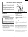
R-209FK
R-209FW
SUPPLEMENTAL SERVICE MANUAL
S2204R209FPW/
MICROWAVE OVEN
MODELS
;;;;
;
;;
;;
;
;
;
;
;
;;;
;;;
;
ON
DEF.
LBS.
QTY. CHECK
R-209FK
R-209FW
In the interest of user-safety the oven should be restored to its original
condition and only parts identical to those specified should be used.
WARNING TO SERVICE PERSONNEL: Microwave ovens contain circuitry capable of producing very high voltage and
current, contact with following parts may result in a severe,
possibly fatal, electrical shock. (High Voltage Capacitor, High
Voltage Power Transformer, Magnetron, High Voltage Rectifier Assembly, High Voltage Harness etc..)
This is a supplemental Service Manual for Models R-209FK and R-209FW. These models are
quite similar to base model R-220EW. Use this supplemental manual together with the Base
Model Service Manual (Refer No. is S1101R220EPW/) for complete operation, service information, etc..
TABLE OF CONTENTS
Page
PRECAUTIONS TO BE OBSERVED BEFORE AND DURING SERVICING TO
AVOID POSSIBLE EXPOSURE TO EXCESSIVE MICROWAVE ENERGY ................... INSIDE FRONT COVER
BEFORE SERVICING ...................................................................................................... INSIDE FRONT COVER
WARNING TO SERVICE PERSONNEL ................................................................................................................ 1
MICROWAVE MEASUREMENT PROCEDURE ................................................................................................... 2
FOREWORD AND WARNING ............................................................................................................................... 3
PRODUCT DESCRIPTION .................................................................................................................................... 4
OPERATION .......................................................................................................................................................... 4
OVEN SCHEMATIC ............................................................................................................................................... 5
TEST PROCEDURE .............................................................................................................................................. 6
COMPONENT REPLACEMENT AND ADJUSTMENT PROCEDURE .................................................................. 7
PICTORIAL DIAGRAM .......................................................................................................................................... 8
CONTROL PANEL CIRCUIT ................................................................................................................................. 9
PARTS LIST ........................................................................................................................................................ 10
PACKING AND ACCESSORIES ......................................................................................................................... 13
This document has been published to be used for after
sales service only.
The contents are subject to change without notice.
SHARP CORPORATION
15
R-209FK
R-209FW
PRECAUTIONS TO BE OBSERVED BEFORE AND
DURING SERVICING TO AVOID POSSIBLE EXPOSURE TO EXCESSIVE MICROWAVE ENERGY
(a) Do not operate or allow the oven to be operated with the door open.
(b) Make the following safety checks on all ovens to be serviced before activating the magnetron or other
microwave source, and make repairs as necessary: (1) interlock operation, (2) proper door closing, (3) seal
and sealing surfaces (arcing, wear, and other damage), (4) damage to or loosening of hinges and latches,
(5) evidence of dropping or abuse.
(c) Before turning on microwave power for any service test or inspection within the microwave generating
compartments, check the magnetron, wave guide or transmission line, and cavity for proper alignment,
integrity, and connections.
(d) Any defective or misadjusted components in the interlock, monitor, door seal, and microwave generation
and transmission systems shall be repaired, replaced, or adjusted by procedures described in this manual
before the oven is released to the owner.
(e) A microwave leakage check to verify compliance with the Federal Performance Standard should be
performed on each oven prior to release to the owner.
BEFORE SERVICING
Before servicing an operative unit, perform a microwave emission check as per the Microwave
Measurement Procedure outlined in this service manual.
If microwave emissions level is in excess of the specified limit, contact SHARP ELECTRONICS
CORPORATION immediately @1-800-237-4277.
If the unit operates with the door open, service person should 1) tell the user not to operate the oven
and 2) contact SHARP ELECTRONICS CORPORATION and Food and Drug Administration's
Center for Devices and Radiological Health immediately.
Service personnel should inform SHARP ELECTRONICS CORPORATION of any certified unit
found with emissions in excess of 4mW/cm2. The owner of the unit should be instructed not to use
the unit until the oven has been brought into compliance.
16
R-209FK
R-209FW
WARNING TO SERVICE PERSONNEL
Microwave ovens contain circuitry capable of producing very high voltage and current, contact with
following parts may result in a severe, possibly
fatal, electrical shock.
(Example)
High Voltage Capacitor, High Voltage Power Transformer, Magnetron, High Voltage Rectifier Assembly, High Voltage Harness etc..
Read the Service Manual carefully and follow all
instructions.
Don't Touch !
Danger High Voltage
When the testing is completed,
1. Disconnect the power supply cord, and then remove
outer case.
2. Open the door and block it open.
3. Discharge high voltage capacitor.
4. Reconnect the leads to the primary of the power
transformer.
5. Reinstall the outer case (cabinet).
6. Reconnect the power supply cord after the outer case is
installed.
7. Run the oven and check all functions.
Before Servicing
1. Disconnect the power supply cord
outer case.
2. Open the door and block it open.
3. Discharge high voltage capacitor.
, and then remove
WARNING:RISK OF ELECTRIC SHOCK.
DISCHARGE THE HIGH-VOLTAGE
CAPACITOR BEFORE SERVICING.
After repairing
The high-voltage capacitor remains charged about 60
seconds after the oven has been switched off. Wait for 60
seconds and then short-circuit the connection of the highvoltage capacitor (that is the connecting lead of the highvoltage rectifier) against the chassis with the use of an
insulated screwdriver.
1. Reconnect all leads removed from components during
testing.
2. Reinstall the outer case (cabinet).
3. Reconnect the power supply cord after the outer case is
installed.
4. Run the oven and check all functions.
Whenever troubleshooting is performed the power supply
must be disconnected. It may, in some cases, be necessary
to connect the power supply after the outer case has been
removed, in this event,
1. Disconnect the power supply cord, and then remove
outer case.
2. Open the door and block it open.
3. Discharge high voltage capacitor.
4. Disconnect the leads to the primary of the power
transformer.
5. Ensure that the leads remain isolated from other
components and oven chassis by using insulation tape.
6. After that procedure, reconnect the power supply cord.
Microwave ovens should not be run empty. To test for the
presence of microwave energy within a cavity, place a cup
of cold water on the oven turntable, close the door and set
the power to HIGH and set the microwave timer for two (2)
minutes. When the two minutes has elapsed (timer at zero)
carefully check that the water is now hot. If the water
remains cold carry out Before Servicing procedure and reexamine the connections to the component being tested.
When all service work is completed and the oven is fully
assembled, the microwave power output should be checked
and microwave leakage test should be carried out.
1
R-209FK
R-209FW
MICROWAVE MEASUREMENT PROCEDURE
A. Requirements:
1) Microwave leakage limit (Power density limit):
The power density of microwave radiation emitted by a microwave oven should not exceed 1mW/cm2 at any point 5cm
or more from the external surface of the oven, measured prior to acquisition by a purchaser, and thereafter (through the
useful life of the oven), 5 mW/cm2 at any point 5cm or more from the external surface of the oven.
2) Safety interlock switches:
Primary interlock relay and door sensing switch shall prevent microwave radiation emission in excess of the requirement
as above mentioned, secondary interlock switch shall prevent microwave radiation emission in excess of 5 mW/cm2 at
any point 5cm or more from the external surface of the oven.
B. Preparation for testing:
Before beginning the actual measurement of leakage, proceed as follows:
1) Make sure that the actual instrument is operating normally as specified in its instruction booklet.
Important:
Survey instruments that comply with the requirement for instrumentation as prescribed by the performance standard
for microwave ovens, 21 CFR 1030.10(c)(3)(i), must be used for testing.
2) Place the oven tray in the oven cavity.
3) Place the load of 275±15 ml (9.8 oz) of tap water initially at 20±5˚C (68˚F) in the center of the oven cavity.
The water container shall be a low form of 600 ml (20 oz) beaker with an inside diameter of approx. 8.5 cm (3-1/2 in.)
and made of an electrically nonconductive material such as glass or plastic.
The placing of this standard load in the oven is important not only to protect the oven, but also to insure that any leakage
is measured accurately.
4) Set the cooking control on Full Power Cooking Mode
5) Close the door and select a cook cycle of several minutes. If the water begins to boil before the survey is completed,
replace it with 275 ml of cool water.
C. Leakage test:
Closed-door leakage test (microwave measurement)
1) Grasp the probe of the survey instrument and hold it perpendicular to the gap between the door and the body of the oven.
2) Move the probe slowly, not faster than 1 in./sec. (2.5 cm/sec.) along the gap, watching for the maximum indication on
the meter.
3) Check for leakage at the door screen, sheet metal seams and other accessible positions where the continuity of the metal
has been breached (eg., around the switches, indicator, and vents).
While testing for leakage around the door pull the door away from the front of the oven as far as is permitted by the closed
latch assembly.
4) Measure carefully at the point of highest leakage and make sure that the highest leakage is no greater than 4mW/cm2.
NOTE: After servicing, record data on service invoice and microwave leakage report.
2
R-209FK
R-209FW
SERVICE MANUAL
MICROWAVE OVEN
R-209FK/ R-209FW
FOREWORD
This Manual has been prepared to provide Sharp Electronics Corp. Service Personnel with Operation and Service
Information for the SHARP MICROWAVE OVENS, R-209FK and R-209FW.
The models R-209FK and R-209FW are quite similar to base model R-220EW (Refer No. is S1101R220EPW/).
It is recommended that service personnel carefully study the entire text of this manual and the base model's manual so
that they will be qualified to render satisfactory customer service.
Check the interlock switches and the door seal carefully. Special attention should be given to avoid electrical shock and
microwave radiation hazard.
WARNING
Never operate the oven until the following points are ensured.
(A) The door is tightly closed.
(B) The door brackets and hinges are not defective.
(C) The door packing is not damaged.
(D) The door is not deformed or warped.
(E) There is no other visible damage with the oven.
Servicing and repair work must be carried out only by trained service personnel.
DANGER
Certain initial parts are intentionally not grounded and present a risk of electrical shock only during servicing.
Service personnel - Do not contact the following parts while the appliance is energized;
High Voltage Capacitor, Power Transformer, Magnetron, High Voltage Rectifier Assembly, High Voltage
Harness;
If provided, Vent Hood, Fan assembly, Cooling Fan Motor.
All the parts marked “*” on parts list are used at voltages more than 250V.
Removal of the outer wrap gives access to voltage above 250V.
All the parts marked “∆” on parts list may cause undue microwave exposure, by themselves, or when they are
damaged, loosened or removed.
SHARP ELECTRONICS CORPORATION
SHARP PLAZA, MAHWAH,
NEW JERSEY 07430-2135
3
R-209FK
R-209FW
PRODUCT DESCRIPTION
SPECIFICATIONS
ITEM
DESCRIPTION
Power Requirements
120 Volts
60 Hertz
Single phase, 3 wire grounded
Power Consumption
1250W / Approx. 10.6 Amperes
Power Output
800 W nominal of RF microwave energy (IEC Test procedure)
Operating frequency 2450 MHz
Case Dimensions
Width 18-1/8"
Height 11-3/8"
Depth 14-5/8"
Cooking Cavity Dimensions
(0.8 Cubic feet)
Width 12-3/8"
Height 8-3/8"
Depth 13"
Control Complement
Touch Control System
Clock (1:00 - 12:59)
Timer (0 - 99 minutes 99 seconds)
Microwave Power for Variable Cooking
Repetition Rate;
P-HI ................................... Full power throughout the cooking time
P-90 .................................................... approx. 90% of FULL Power
P-80 .................................................... approx. 80% of FULL Power
P-70 .................................................... approx. 70% of FULL Power
P-60 .................................................... approx. 60% of FULL Power
P-50 .................................................... approx. 50% of FULL Power
P-40 .................................................... approx. 40% of FULL Power
P-30 .................................................... approx. 30% of FULL Power
P-20 .................................................... approx. 20% of FULL Power
P-10 .................................................... approx. 10% of FULL Power
P-0 ...................................... No power throughout the cooking time
POPCORN pad, MINUTE PLUS pad
Instant Start pads, EXPRESS DEFROST pad
Number selection pads, TIMER/CLOCK pad
POWER LEVEL pad
STOP/CLEAR pad, START pad
Oven Cavity Light
Yes
Safety Standard
UL Listed.
FCC Authorized
DHHS Rules, CFR, Title 21, Chapter 1, Subchapter J
OPERATION
DESCRIPTION OF OPERATING SEQUENCE
POWER OUTPUT REDUCTION
If the oven is set for more than 20 minutes at 80, 90 or 100% power level, after the first 20 minutes the power level will
automatically adjust itself to 70% power to avoid overcooking.
4
;;;;
;;;;
;;;
;;
;;;;
;;;
;;
;;;;;
R-209FK
R-209FW
TOUCH CONTROL PANEL
ON
DEF.
LBS.
QTY. CHECK
NOTE:
Some one-touch cooking features such as
"MINUTE PLUS" are disabled after three minutes when the oven is not in use. These features
are automatically enabled when the door is
opened and closed or the STOP/ CLEAR pad is
pressed.
SCHEMATIC
NOTE: CONDITION OF OVEN
1. DOOR CLOSED
2. CLOCK APPEARS ON DISPLAY
NOTE: " " indicates components with potential above 250V.
C/T FUSE
MAGNETRON
THERMAL CUT-OUT
COM.
POWER
TRANSFORMER
N.O.
(RY-2)
(RY-1)
A3
PRIMARY
INTERLOCK
RELAY
CAPACITOR
0.86µF
CONTROL UNIT
A1
B1
B2
DOOR
SENSING
SWITCH
TTM
OL
OVEN
LAMP
MONITOR
SWITCH
FM
TURNTABLE
MOTOR
FAN
MOTOR
SECONDARY
INTERLOCK
SWITCH
Figure O-1. Oven Schematic-Off Condition
5
MAGNETRON
GRN
120V AC
60 Hz
RECTIFIER
R-209FK
R-209FW
TEST PROCEDURES
PROCEDURE
LETTER
B
COMPONENT TEST
POWER TRANSFORMER TEST
1.
2.
3.
4.
Disconnect the power supply cord, and then remove outer case.
Open the door and block it open.
Discharge high voltage capacitor.
Disconnect the primary input terminals and measure the resistance of the transformer with an
ohmmeter. Check for continuity of the coils with an ohmmeter. On the R x 1 scale, the resistance of
the primary coil should be less than 1 ohm and the resistance of the filament coil should be less than
1 ohm. And the resistance of the high voltage coil should be obtained in the table below.
Part number of power transformer
RTRN-A672WRZZ
RTRN-A675WRZZ
RTRN-A646WRZZ
5.
6.
7.
8.
Resistance of the high voltage coil
Approx. 144 Ω
Approx. 157 Ω
Approx. 132 Ω
Reconnect all leads removed from components during testing.
Reinstall the outer case (cabinet).
Reconnect the power supply cord after the outer case is installed.
Run the oven and check all functions.
(HIGH VOLTAGES ARE PRESENT AT THE HIGH VOLTAGE TERMINAL, SO DO NOT ATTEMPT TO
MEASURE THE FILAMENT AND HIGH VOLTAGE.)
J
KEY UNIT TEST
1.
2.
3.
4.
5.
6.
7.
8.
Disconnect the power supply cord and then remove outer case.
Open the door and block it open.
Discharge high voltage capacitor.
If the display fails to clear when the STOP/CLEAR pad is depressed, first verify the flat ribbon cable
is making good contact, verify that the door sensing switch operates properly; that is the contacts are
closed when the door is closed and open when the door is open. If the door sensing switch is good,
disconnect the flat ribbon cable that connects the key unit to the control unit and make sure the door
sensing switch is closed (either close the door or short the door sensing switch connector). Use the
Key unit matrix indicated on the control panel schematic and place a jumper wire between the pins
that correspond to the STOP/CLEAR pad making momentary contact. If the control unit responds by
clearing with a beep the key unit is faulty and must be replaced. If the control unit does not respond,
it is faulty and must be replaced. If a specific pad does not respond, the above method may be used
(after clearing the control unit) to determine if the control unit or key pad is at fault.
Reconnect all leads removed from components during testing.
Re-install the outer case (cabinet).
Reconnect the power supply cord after the outer case is installed.
Run the oven and check all functions.
G6
G5
G4
G7
BEVERAGE
6
2
G8
FRESH
3
VEGETABLES
TIMER
ROLLS
MUFFINS CLOCK
FROZEN
9
ENTREES
G9
G10
KEY UNIT
6
5
0
8
G3
G2
G1
DINNER MINUTE
PLATE
PLUS
EXPRESS POWER
4
DEFROST LEVEL
STOP
BAKED
1
POTATOES CLEAR
7
POPCORN START
R-209FK
R-209FW
COMPONENT REPLACEMENT AND ADJUSTMENT PROCEDURE
WARNING AGAINST HIGH VOLTAGE:
Microwave ovens contain circuitry capable of producing very high voltage and current, contact with following parts may
result in severe, possibly fatal, electric shock.
(Example)
High Voltage Capacitor, Power Transformer, Magnetron, High Voltage Rectifier Assembly, High Voltage Harness etc..
WARNING:
Avoid possible exposure to microwave energy. Please follow the instructions below before
operating the oven.
1. Disconnect the power supply cord.
2. Visually check the door and cavity face plate for damage
(dents, cracks, signs of arcing etc.).
4. The door is bent or warped.
5. There are defective parts in the door interlock system.
6. There are defective parts in the microwave generating
and transmission assembly.
7. There is visible damage to the oven.
Carry out any remedial work that is necessary before
operating the oven.
Do not operate the oven if any of the following conditions
exist;
1. Door does not close firmly.
2. Door hinge, support or latch hook is damaged.
3. The door gasket or seal is damaged.
Do not operate the oven:
1. Without the RF gasket (Magnetron).
2. If the wave guide or oven cavity are not intact.
3. If the door is not closed.
4. If the outer case (cabinet) is not fitted.
WARNING FOR WIRING
To prevent an electric shock, take the following precautions.
1. Before wiring,
1) Disconnect the power supply cord.
2) Open the door and block it open.
3) Discharge the high voltage capacitor and wait for 60
seconds.
2. Don’t let the wire leads touch to the followiong parts;
1) High voltage parts:
Magnetron, High voltage transformer, High voltage
capacitor and High voltage rectifier assembly.
2) Hot parts:
Oven lamp, Magnetron, High voltage transformer
and Oven cavity.
3) Sharp edge:
Bottom plate, Oven cavity, Waveguide flange,
Chassis support and other metallic plate.
4) Movable parts (to prevent a fault)
Fan blade, Fan motor, Switch.
3. Do not catch the wire leads in the outer case cabinet.
4. Insert the positive lock connector until its pin is locked
and make sure that the wire leads do not come off even
if the wire leads are pulled.
5. To prevent an error function, connect the wire leads
correctly, referring to the Pictorial Diagram.
POWER TRANSFORMER REMOVAL
9. Remove the transformer.
10.Now the power transformer is free.
Re-install
1. Rest transformer on the bottom plate with its primary
terminals toward the oven face plate.
2. Secure transformer with two (2) screws to the bottom
plate from above.
3. Secure transformer with two (2) screws to the bottom
plate from below.
4. Re-connect wire leads (primary and high voltage) and
filament leads to the power transformer, magnetron and
high voltage capacitor, referring to "Pictorial Diagram".
5. Re-install outer case and check that the oven is operating
properly.
1. Disconnect the power supply cord and remove outer
case.
2. Open the oven door and block it open.
3. Discharge high voltage capacitor.
4. Disconnect the wire leads of main wire harness and
H.V. wire (for using RTRN-A646WRZZ) from power
transformer.
5. Disconnect the lead from magnetron filament.
6. Disconnect the lead(s) of the power transformer from
high voltage capacitor.
7. Remove the two (2) screws holding the transformer to
bottom plate from below.
8. Remove the two (2) screws holding the transformer to
bottom plate from above.
7
1
1
2
3
ORG
ORG
RED
G
CN-A
1 ORG
2
3 WHT
3
8
WHT
WHT
WHT
GRY
TURNTABLE
MOTOR
GRY
ORG
ORG
4
WHT
GRY
ORG
ORG
POWER
TRANSFORMER
MAGNETRON
H.V.
RECTIFIER
HIGH
VOLTAGE
CAPACITOR
HIGH VOLTAGE COMPONENTS
BLK
N
5
GRY
POWER
TRANSFORMER
HIGH
VOLTAGE
CAPACITOR
5
H
6
WHT
HIGH VOLTAGE
WIRE B
H.V.
RECTIFIER
4
ORG
MAGNETRON
HIGH VOLTAGE COMPONENTS (for using RTRN-A646WRZZ)
ORG
RED
MAGNETRON
THERMAL CUT-OUT
NOTE:
The neutral (WHT) wire must be
connected to the terminal with "N" mark
on the power supply cord
POWER SUPPLY CORD
120V 60Hz
3
Figure S-1. Pictorial Diagram
SECONDARY
INTERLOCK SWITCH
COM
N.O.
COM
GRY
GRY
FAN MOTOR
WHT
GRY
RED
2
MONITOR
SWITCH
N.C.
RED
GRN
GRY
OVEN LAMP
D
CN-A
CN-B
1 GRY
2 GRN
COM
N.O.
WHT
RED
1
RY2
SP1
C/T FUSE
RED
C
RY1
1
CN-B
F
DOOR
SENSING SWITCH
E
GRN
GRN
BLK
NOTE:
The grounding conductor of the power
supply cord has been grounded by
power supply cord fixing screw.
The screw must always be kept tight.
B
2
CONTROL UNIT
WHT
A
H
To chassis support
GRD
R-209FK
R-209FW
6
A
B
C
D
E
F
G
H
4
DOOR
SENSING
SWITCH
GND
B1
B2
COM
NO
A1
c
RY2
RY1
C1 0.1µ/50v
C2 470µ/25v
3.3k 1/4w
R30
SP1
PKM22EPT
Q20
DTA143EKA
R41 15k
C20
0.1µ
/25v
Q30 DTA143EKA
Q10 DTA143EKA
C10
0.1µ
/25v
5
R5
1k
ZD1
HZ4C3
R73 15k
R72 15k
R71 15k
R70 15k
(J12) 20k
(J10) 7.5k
(J14)
VC
(J13) 4.7k
(J15) 4.7k C7
0.1µ
(J11) 10k /25v
54
14
P43
P42
P41
P40
15
AVSS
AVREF
AVDD
VDD
VD1
OCS4
OCS3
RESET
TEST
VSS
1
R02
G10
G9
G8
G7
IC1
P20
6
G5
KEY UNIT
FRESH
3
VEGETABLES
ROLLS TIMER
MUFFINS CLOCK
FROZEN
9
ENTREES
BEVERAGE
G6
29
44
8
0
5
2
G4
30
COM2
COM3
SEG0
SEG1
SEG2
SEG3
SEG4
SEG5
SEG6
SEG7
SEG8
SEG9
SEG10
SEG11
SEG12
45
S9
S8
G3
S10
G2
G1
7
POPCORN START
DINNER MINUTE
PLATE
PLUS
EXPRESS POWER
4
DEFROST LEVEL
STOP
BAKED
1
POTATOES CLEAR
5
Figure S-2. Control Panel Circuit
: IF NOT SPECIFIED, 1/10W ± 5%
: IF NOT SPECIFIED, 1SS270A
7
6
5
4
3
2
C6
0.1µ/25v
C5 0.1µ/25v
4
NOTE
D40
D22
–
+
C8 220µ/10v
C21 10µ/35v
Q22
KRA105M
Q21
DTD143ES
VR
R4
910 1/2w
R10 15k
R20 15k
Q1
2SA1037AK
R78 220k
VRS1 10G471K
b
–
R77 220k
C3 0.01µ/25v
C11 0.01µ/25v
C4
R76 220k
SEG19
ON DEF. LBS QTY. CHECK
3
AC(H)
MICRO
OVEN LAMP
TURNTABLE
MOTOR
FAN MOTOR
a
d
D20
D21
9
R40 4.7k
3
C40 0.01µ/25v
R50 20kF
0.01µ
/25v
R6 15k
R75 220k
+
VC3
BZ
–
VC2
R00
+
VC1
R01
D4
SEG18
D2
SEG17
GND
SEG16
K00
1
SEG15
K01
GND
S7
S6
S12
D3
S5
D1
P21
A3
P22
H
P23
2
R67
15k
AC120V
60Hz
SEG14
LIQUID CRYSTAL DISPLAY
S4
AC(N)
SEG13
G
K02
D
K03
CPU UNIT
S11
R65
15k
2
R64
15k
POWER UNIT
S3
S2
D1-D4
1N4002
S1
1
C1
F
C2
C3
E
R63
15k
C
COM0
B
COM1
A
R62
15k
1
R66
15k
T1
R-209FK
R-209FW
6
A
B
C
6
D
E
F
G
H
R03
(J1)
R-209FK
R-209FW
PARTS LIST
Note: The parts marked “∆” may cause undue microwave exposure.
The parts marked “*” are used in voltage more than 250V.
REF. NO.
PART NO.
DESCRIPTION
QSW-MA137WRE0
FFS-BA025WRKZ
FACCDA086WREZ
FACCDA081WRE0
FACCDA082WRE0
RTRN-A672WRZZ
RTRN-A675WRZZ
RTRN-A646WRZZ
FH-DZA103WRKZ
FH-DZA081WRK0
FH-DZA082WRK0
FH-DZA087WRK0
RC-QZA228WRE0
RC-QZA201WRE0
RC-QZA284WRZZ
RMOTEA383WRE0
RMOTEA355WRE0
RMOTEA392WRZZ
RV-MZA306WRZZ
RV-MZA226WRE0
RLMPTA082WRZZ
RMOTDA186WRE0
RMOTDA211WRE0
RMOTDA229WRE0
RTHM-A116WRE0
RTHM-A078WRE0
RTHM-A098WRE0
Secondary interlock switch & door sensing switch
C/T fuse & monitor switch(AM51620C53Y1) assembly
Power supply cord
Power supply cord (Interchangeable)
Power supply cord (Interchangeable)
Power transformer
Power transformer (Interchangeable) for production use
Power transformer (Interchangeable)
High voltage rectifier
High voltage rectifier (Interchangeable)
High voltage rectifier (Interchangeable)
High voltage rectifier (Interchangeable)
High voltage capacitor
High voltage capacitor (Interchangeable)
High voltage capacitor (Interchangeable)
Fan motor
Fan motor (Interchangeable)
Fan motor (Interchangeable)
Magnetron
Magnetron (Interchangeable)
Oven lamp
Turntable motor
Turntable motor (Interchangeable)
Turntable motor (Interchangeable)
Thermal cut-out 125˚C (MG)
Thermal cut-out 125˚C (MG) (Interchangeable)
Thermal cut-out 125˚C (MG) (Interchangeable)
Q'TY
CODE
2
1
1
1
1
1
1
1
1
1
1
1
1
1
1
1
1
1
1
1
1
1
1
1
1
1
1
AH
AS
AN
AP
AV
ELECTRIC PARTS
*
*
*
*
*
*
*
*
*
*
*∆
*∆
1- 1
1- 2
1- 3
1- 3
1- 3
1- 4
1- 4
1- 4
1- 5
1- 5
1- 5
1- 5
1- 6
1- 6
1- 6
1- 7
1- 7
1- 7
1- 8
1- 8
1- 9
1-10
1-10
1-10
1-11
1-11
1-11
-BH
AS
AQ
AQ
AQ
AT
AW
AU
AV
AU
BL
BE
AL
AW
AS
AQ
AK
AK
AK
High voltage wire B (Ref. 6- 6 QW-QZA242WRZZ) should be needed to use this power transformer.
CABINET PARTS
2222-
1
1
2
3
GCABUA756WRPZ
GCABUA696WRP0
GDAI-A304WRW0
GLEGPA074WRE0
Outer case cabinet [R-209FK]
Outer case cabinet [R-209FW]
Bottom plate
Foot
33333333-
1
2
2
2-1
2-1
3
4
5
DPWBFC196WRUZ
FPNLCB638WRKZ
FPNLCB639WRKZ
FUNTKB112WREZ
FUNTKB113WREZ
QCNC-A013WRZZ
RLCDSA089DRZZ
XEPSD30P08XS0
Control unit
Control panel frame with key unit [R-209FK]
Control panel frame with key unit [R-209FW]
Key unit [R-209FK]
Key unit [R-209FW]
Rubber connector
Liquid crystal display
Screw; 3mm x 8mm
4- 1
4- 2
4- 3
4- 4
4- 5
4- 6
4- 7
4- 8
4- 9
4-10
4-11
4-12
4-13
4-14
4-15
4-16
4-17
4-18
PHOK-A105WRF0
LANGQA530WRWZ
PCUSUA502WRP0
LBNDKA038WRP0
NFANJA029WRE0
PDUC-A694WRF0
*************
GLEGPA073WRF0
LANGTA318WRP0
PCUSGA389WRP0
PCOVPA276WRE0
PCOVPA342WRF0
PCOVPA343WRF0
PCUSUA443WRP0
PDUC-A700WRF0
PPACGA097WRE0
PCUSUA474WRP0
PCUSGA133WRP0
Latch hook
Light mount plate
Waterproof cushion
Capacitor holder
Fan blade
Fan duct
Oven cavity (Not replaceable part)
Leg
Chassis support
Cushion
Waveguide cover
B-cover Right
B-cover Left
Cushion
Air separator
O-ring
Cushion
Cushion
5- 1
FDORFA321WRT0
Door panel
1
1
1
2
BC
AY
AF
AC
1
1
1
1
1
1
1
3
BD
AE
AM
AA
1
1
2
1
1
1
1
1
1
1
1
1
1
2
1
1
1
1
AL
AP
AD
AF
AL
AG
-AD
AE
AG
AM
AH
AH
AE
AN
AG
AC
AC
1
AT
CONTROL PANEL PARTS
OVEN PARTS
∆
∆
DOOR PARTS
∆
10
R-209FK
R-209FW
∆
∆
∆
∆
REF. NO.
5- 2
5- 2
5- 3
5- 3
5- 4
5- 5
5- 6
5- 7
5- 8
PART NO.
GWAKPA772WRFZ
GWAKPA859WRRZ
HPNL-A746WRRZ
HPNL-A777WRRZ
LSTPPA175WRF0
MSPRTA084WRE0
PSHEPA622WRE0
GCOVHA390WRF0
XCPSD40P08000
DESCRIPTION
Door frame [R-209FK]
Door frame [R-209FW]
Door screen [R-209FK]
Door screen [R-209FW]
Latch head
Latch spring
Sealer film
Choke cover
Screw : 4mm x 8mm
6666666666-
1
1
2
2
3
4
5
6
7
8
FROLPA098WRKZ
FROLPA089WRK0
NTNT-A107WREZ
NTNT-A094WRE0
TINSEA934WRRZ
TLAB-A183WRR0
FW-VZB892WREZ
QW-QZA242WRZZ
TCAUAA268WRRZ
TCAUAA257WRRZ
Turntable support
Turntable support (Interchangeable)
Turntable
Turntable (Interchangeable)
Instruction book
Service label
Main wire harness
High voltage wire B (using for Ref. 1-4 RTRN-A646WRZZ)
DHHS caution label
Monitor caution
7- 1
7- 2
7- 3
7- 4
7- 5
7- 6
7- 7
7- 8
7- 9
7- 9
7-10
7-11
7-12
XHPSD40P08K00
LX-EZA042WRE0
LX-WZA028WRE0
XHTSD40P12RV0
XHTSD40P08RV0
XHPSD30P06000
LX-CZ0052WRE0
XOTSD40P12000
XOTSF40P08000
XOTSE40P08000
LX-CZA070WRE0
XHPSD40P08000
XOTSD40P08000
Screw :
Special
Special
Screw :
Screw :
Screw :
Special
Screw :
Screw :
Screw :
Special
Screw :
Screw :
Q'TY
1
1
1
1
1
1
1
1
4
CODE
AR
1
1
1
1
1
1
1
1
1
1
AP
AP
AU
AN
2
2
1
1
5
1
2
6
4
4
2
3
7
AA
AB
AB
AA
AA
AA
AA
AA
AA
AA
AC
AA
AA
AT
AT
AE
AB
AG
AK
AA
MISCLANEOUS
*
AB
AU
AF
AC
AC
SCREWS AND WASHERS
4mm x 8mm
screw
washer
4mm x 12mm
4mm x 8mm
3mm x 6mm
screw
4mm x 12mm
4mm x 8mm [R-209FK]
4mm x 8mm [R-209FW]
screw (Torx tamper proof screw)
4mm x 8mm
4mm x 8mm
HOW TO ORDER REPLACEMENT PARTS
To have your order filled promptly and correctly, please furnish the following information.
1. MODEL NUMBER
2. REF. NO.
3. PART NO.
4. DESCRIPTION
Order Parts from the authorized SHARP parts Distributor for your area.
Defective parts requiring return should be returned as indicated in the Service Policy.
11
R-209FK
R-209FW
2
1
4
3
6
5
OVEN AND CABINET PARTS
7-12
7-10
A
A
7-12
2-1
7-9
7-12
7-10
1-9
B
B
7-12
4-3
7-11
4-2
C
1-8
4-17
C
7-9
6-8
6-7
7-4
4-5
4-14
1-2
1-3
4-14
D
7-5
4-6
7-5
D
1-6
E
4-7
7-5
6-4
A
4-11
A
1-7
1-5
E
6-2
7-3
1-11
7-1
7-6
4-9
4-4
4-16
7-7
1-10
1-2
7-2
6-1
F
1-1
4-10
7-1
F
4-1
4-15
7-12
1-1
4-18
4-3
4-8
1-4
2-2
G
G
7-8
2-3
4-13
7-12
7-8
7-8
2-3
7-8
H
H
4-12
7-8
1
2
4
3
12
5
6
R-209FK
R-209FW
2
1
Befor attaching Control unit to
Control panel, foil side of Control
unit must be cleaned by ethylalcohol.
A
4
3
6
5
MISCELLANEOUS
CONTROL PANEL PARTS
Actual wire harness may be different than illustration.
3-1
3-2
3-4
3-5
A
6-5
3-5
3-3
6-6
(using for Ref. 1-4 RTRN-A646WRZZ)
B
B
5-6
DOOR PARTS
5-8
5-7
C
C
3-2-1
5-1
5-8
5-2
5-3
D
D
5-4
5-5
E
TOP PAD ASSEMBLY
E
FPADBA387WRK0
PACKING AND ACCESSORIES
DOOR PROTECTION SHEET
POLYETHYLENG BAG
SPADPA580WRE0
SSAKHA014WRE0
PLASTIC SHEET (for R-209FK)
6-3 OPERATION MANUAL
SPADPA615WREZ
F
F
6-2 TURNTABLE TRAY
FOAM SHEET
SPAKHA014WREZ
MICROWAVE
OVEN
BOTTOM PAD ASSEMBLY
FPADBA388WRK0
6-1
G
TURNRABLE SUPPORT
G
INTO THE
OVEN CAVITY
H
PACKING CASE
FPAK-A428WRKZ [R-209FK]
FPAK-A427WRKZ [R-209FW]
Not replaceable items.
TRAY PAD ASSY
(CPADBA244WRK0)
1
2
4
3
13
5
6
H
R-209FK
R-209FW
COPYRIGHT © 2002 BY SHARP CORPORATION
ALL RIGHTS RESERVED.
No part of this publication may be reproduced,
stored in retrieval systems, or transmitted in any
form or by any means, electronic, mechanical,
photocopying, recording, or otherwise, without prior
written permission of the publisher.
2002 SHARP CORP. (2S1.700E) Printed in U.S.A
14