1
US007394358B2
(12) Ulllted States Patent
(10) Patent N0.:
Cherry
(54)
(75)
(45) Date of Patent:
7,195,169 B2*
3/2007 Bhatia et a1. ......... .. 235/462.46
MONITORING
7,199,716 B2*
4/2007
7,221,668 B2*
5/2007 Twitchell, Jr. ............. .. 370/338
7,243,849 B2*
7/2007 Lapstun 61711. ....... .. 235/46245
I
_
C
_
D Ch
mg
'
E
erry’
OR
ugene’
S
(U )
AssigneeZ Datalogic scanning’ Inc” Eugene’ OR
(Us)
(*)
Jul. 1, 2008
METHOD AND SYSTEM FOR INVENTORY
nvemor'
(73)
US 7,394,358 B2
Notice?
Subjecno any disclaimeratheterm Ofthis
$2318 llssii‘glide‘ll6o7rdidlsusted under 35
'
'
'
y
y '
Shanks etal. .......... .. 340/5721
2001/0008390 A1
7/2001 Berquist et a1. ........ .. 340/10.3l
2004/0076232 A1
4/2004 Akiyama etal. ..... .. 375/24008
2004/0105024 A1
6/2004
2004/0118916 A1
6/2004 He ........................... .. 235/383
2004/0217774 A1
11/2004 C1106 ......................... .. 326/30
2005/0212676 A1
9/2005
Takahashi ............ .. 348/333.01
Steinberg ............... .. 340/5728
(21)
APPLNQ; 11/230,365
2006/0208859 A1
9/2006 Hougen et a1. ........... .. 340/l0.1
2006/0208890 Al*
9/2006
(22)
Flledi
2007/0095911 Al*
5/2007 Shimura et a1. ...... .. 235/46246
sell-19,2005
(65)
Ehrman e181. ......... .. 340/5721
Prior Publication Data
US 2007/0063817 A1
Mar. 22, 2007
OTHER PUBLICATIONS
(51)
Int. Cl.
G08B 26/00
(200601)
(52) U.S.Cl. .............. .. 340/505;340/572.1;235/46246
<58
U.S1. Appl.11\T((1).“ll/084,072d, ?leilhMC: 16, 2005 to l?obertw. I-Iougen
1??"egLZ0 $185M“ Me FACEREID R1346; ZTMRUOH'XI
"2217;121:111822226.61.8682?
235/46246, 385
See application ?le for complete search history.
(56)
‘ e“
(Continued)
US. PATENT DOCUMENTS
(57)
5,640,002 A *
6/1997
Ruppeit et a1. ....... .. 235/462.46
5,659,167
8/1997
Wang et a1
A
6,318,636 B1
.....
. . . . . . ..
1/2001 Hash et a1 ~~~~ -~
Tam
‘
)
Primary Examinerilohn A. TWeel, Jr.
(74) Attorney, Agent, or FirmiStoel Rives LLP
References Cited
6,170,748 B1 *
'
235/472
3405721
.. ... ... ... .. ..
A system and method for providing operational feedback of
. . . . . . . . . . ..
Systems using electronic tags Such as radio frequency identi
23 5/47201
?cation (RFID) tags for inventory monitoring, including ref
6,456,239 Bl *
6’607’l34 Bl *
9/2002 Werb et a1. ................ .. 342/463
8/2003 Bard et a1‘ """""" " 235/462'46
erence tags, that provide feedback to Check if all inventory
items have been identi?ed. In one con?guration, the RFID
6,687,460
2/2004
B2
11/2001 Reynolds et a1~
ABSTRACT
Muller
...........
. . . . . . . .. 396/534
reader actuates
"" " 455/4221
tinuing to read multiple RFID tags in the read Zone until a
6’745’027 B2
6/2004 Twltchell’ Jr‘
6,758,403 Bl *
7/2004 Keys et a1. ........... .. 235/462.46
6,895,196 B2
5/2005
UchiZono et a1.
7,042,358 B2 *
5/2006
Moore ............. ..
7,063,256 B2
6/2006 Anderson et a1. ......... .. 235/385
a Single trigger pull’
tenninating event Occurs
........... .. 399/75
'
.. 340/572.l
30 Claims, 5 Drawing Sheets
14 _\
KEYBOARD
13
10
DISPLAY J
j
24
20010/
BEEPER
“J
11
15
1533:5355 J
PROCESSING
CORE
22
LED
RFID
INTERROGATOR
,,
F
m
20
/4 COMMUNICATIONS
16
the reader COn_
RADIO
ANTENNA
TRIGGER
w
19
US 7,394,358 B2
Page 2
OTHER PUBLICATIONS
Falcon® 5500 RFID Mobile Hybrid Computer user manual (Adden
Falcon® 5500 RFID Mobile Hybrid Computer user manual (Adden
dum) R44-2494 (Rev. X3) PSC Inc. no date.
Falcon® 5500 RFID Mobile Hybrid Computer user manual (Adden
dum) R44-2494 (Rev. X4) PSC Inc. no date.
Of?ce Action dated Dec. 20, 2007 for US. Appl. No. 11/084,072 of
dum) R44-2494 (Rev. A) PSC Inc. (about Aug. 2006).
Robert Hougen (application published as US2006/ 0208859).
* cited by examiner
US. Patent
Jul. 1, 2008
Decoding Properties
Sheet 1 0f 5
US 7,394,358 B2
okEI
Liggm
Pistol Trigger
0
/ 0
"Scan" Key
Disable
O /
Bar Code
C.)
0
Image
0
(0)
RFID
0
@ Decoding
$§l> 9:34AM
© 2004 PSC Inc.
[5.3
US. Patent
Jul. 1, 2008
Sheet 2 of5
14\
KEYBOARD
AUDIO/
13
10
DISPLAY J
_)
J11
BEEPER
US 7,394,358 B2
15
BARCODE
SCANNER
J
PROCESSING
CORE
22
LED
ID
IN
17 J
K1
RFID
20
/— COMMUNICATIONS
16
OGATOR
RADIO
ANTENNA
TRIGGER
w
19
US. Patent
Jul. 1,2008
HARDWARE
TRIGGER PRESS
Sheet 3 of5
US 7,394,358 B2
SOFTWARE
FUNCTION CALL
BEGIN RFID TAG /
/
50
54
INVENTORY
OPERATION
5,
INSTRUCT RFID /_
{\1
5
l4 .
56
INTERROGATOR
TO INVENTORY
TAGs
5s
INDICATE NEW
YES
/_ 60
TAG DATA
_
’
FOUND
NO
62
ALL TAGs
YES
_
OPERATION
TIMEOUT?
NEW
TAG DATA
YES
72
V
/—
END RFID TAG
lNVENTORY
US. Patent
Jul. 1, 2008
{2.9
Decoding Properties
IE7
110
100
m
| Decoding
Con?gureProperties
?ettings |c=|=>
Audio
mm
Q 102
Volume =U/
112
Report Frequency
Beep
Type
Duration
114~\ IE Read Class 0 Tags
//\106
l2 Read Class 1 Tags
|
116-’
|
Number [ ]=I
I Decoding |
1 Tag
\%
'
Tone
US 7,394,358 B2
Sheet 4 of 5
\_/108
WE
@ Decoding ?g» 10:35AM? %
@ 2004 PSC Inc.
© 2004 PSC Inc.
[2.8
Decoding Properties
EIOKEI
| Con?gure ?ettings |c=|=>
Total Read Timeout
120
/
"122
New Tag Timeout
Minimum Tag Count
U/K126
Decoding
We
@ 2004 PSC Inc.
US. Patent
130\
132a
Jul. 1,2008
Sheet 5 of5
134
/
\
13
El
2C1E 133%
%1321)] 132(11
Mega@0958M58
US 7,394,358 B2
US 7,394,358 B2
1
2
METHOD AND SYSTEM FOR INVENTORY
MONITORING
being used to illustrate preferred embodiments When read in
COPYRIGHT NOTICE
BRIEF DESCRIPTION OF THE DRAWINGS
conjunction With the accompanying draWings.
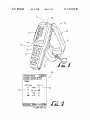
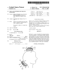
FIG. 1 is a diagrammatic vieW of a combined RFID system
A portion of the disclosure of this patent document con
comprised of an RFID reader, optical code reader and data
terminal according to a preferred embodiment.
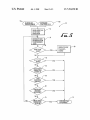
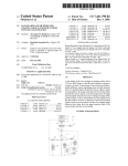
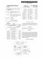
FIG. 2 is a simpli?ed block diagram of an RFID system of
tains material that is subject to copyright protection. The
copyright oWner has no objection to the facsimile reproduc
tion by anyone of the patent document or the patent disclo
FIG. 1.
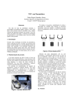
FIG. 3 is a screen vieW for an input scheme of a program for
sure, as it appears in the Patent and Trademark Of?ce patent
?le or records, but otherWise reserves all copyright rights
Whatsoever per 37 CFR § 1.71.
the system of FIG. 1.
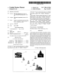
FIG. 4 is a diagram of an RFID system illustrating an RFID
reading ?eld relative to an RFID tag.
BACKGROUND
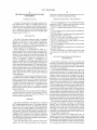
FIG. 5 is a How chart of a method of RFID inventory
monitoring according to a preferred embodiment.
The ?eld of the present disclosure relates to operating
FIG. 6 is a screen shot for an input scheme of an audio
methods and techniques for systems employing electronic
portion for the system of FIG. 1.
identi?cation tags such as radio frequency identi?cation
(RFID) tags. In particular, methods and apparatus are
described herein for improving and facilitating operation of
electronic tag and RFID reading systems.
20
FIG. 8 is a screen shot for an input scheme of read limits for
the system of FIG. 1.
RFID interrogators use electromagnetic energy as a
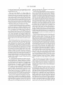
FIG. 9 is an illustration of a reference tag setup in a shelf
environment and a data reader With a display of reference
medium through Which to send information. Typically, RFID
tags are a?ixed to various articles for alloWing identi?cation
of items in a sales transaction or tracking movement of the
articles through a Warehouse location. In a typical RFID tag
system, the components forming the interrogator are a
receiver, a transmitter, an antenna, a microprocessor and
memory. Through the use of the interrogator, RFID tags are
enabled to receive, store and transmit article-identifying data
25
30
are described beloW With reference to an RFID tag, a practi
tioner in the art Will recogniZe the principles described herein
the radio frequency (RF) energy transmitted from the reader.
35
battery. RFID tags may be loW or high frequency depending
on the applications.
Existing RFID systems do not provide feedback to the user
pletely covered an inventory area. The present inventors have
recogniZed that it may be advantageous for a user to knoW
inventory monitoring performance.
information to a user. The terminal 12 includes LED indica
tors 17 and 17a. The terminal 12 includes a front WindoW 15
through Which a data reading device, for example, an imaging
completely cover an inventory area. For applications With
reading systems for improving operational ef?ciency and
are viable to other applications.
FIG. 1 illustrates a handheld combination device 10 having
a portable terminal section 12, a handle section 18 and an
RFID antenna section 20. The portable terminal section 12
includes a display screen 13 and a keypad section 14 for
providing control or data input into the terminal or displaying
40
What the RFID antenna coverage area is, so that the user may
multiple inventory items such as in a Warehouse, existing
RFID systems provide no indication Whether all sWept RFID
tags have been read.
The present inventors have recogniZed the desirability of
providing methods and systems in the operation of RFID
The preferred embodiments Will noW be described With
reference to the draWings. While the preferred embodiments
Without an internal poWer source and draW their poWer from
of an RFID reader to indicate Whether or not the user com
tags.
DETAILED DESCRIPTION OF PREFERRED
EMBODIMENTS
Without manual handling operations. RFID tags may be read
only or read-Write. Passive RFID tags may be implemented
Active RFID tags may include a poWer source such as a
FIG. 7 is a screen shot for an input scheme of report settings
for the system of FIG. 1.
45
reader or a laser scanner, may operate to read optical codes.
The data reading device may detect an image Within a ?eld of
vieW. The reader 10 may be a combination system With vari
ous functions controlled by the terminal 12 as the user selects
input by using the touch display screen 13. Altemately, the
user may input data through the keypad section 14. Within a
particular mode of operation, the user may activate a particu
50
lar read operation by actuating the pistol trigger 19 located on
the front of the handle 18. The user may also activate a
particular read operation by using a scan key trigger 25 on the
SUMMARY
The preferred embodiment of the disclosure is a method of
keyboard 14 or another virtual sWitch on the touch screen 13.
55
RFID reading comprising the steps of: 1) pointing a handheld
The combination reader 10 sends out an interrogation sig
nal during a read operation in response to an appropriate
actuation, such as activating pistol trigger 19 or scan key
RFID reader toWard a read area containing item tags and
trigger 25. Upon receipt of the interrogation signal, an RFID
reference tags; 2) actuating a trigger on the handheld RFID
reader to commence reading RFID tags; 3) performing a ?rst
tag (Whether it is a passive tag or an active tag), may respond
by sending out a return signal containing the tag data. The
read operation, Wherein the read operation comprises inter
60
rogating and sensing at least one RFID tag in the read area; 4)
continuing With a subsequent read operation comprising
combination reader 10 then senses the return signal and pro
cesses the signal to obtain the data.
An RFID read operation in a handheld device may be
interrogating and reading at least one tag in the read area; and
de?ned by actuation of a sWitch (e. g. trigger 19) and a single
5) the RFID reader discontinuing subsequent read operations
read command sent to the combination reader 10 to read all
once a termination criteria is met.
These and other aspects of the disclosure Will become
apparent from the folloWing description, the description
65
the tags Within a radio frequency (RF) ?eld. The combination
reader 10 may read multiple tags Within a single read opera
tion or tag inventory operation. Each of the tags interrogated
US 7,394,358 B2
3
4
in a given read operation may be read sequentially according
operation continuing until a subsequent (second) trigger pull
to a suitable protocol such as query response protocol or air
that noti?es the system to terminate.
interface protocol (AIP).
There are various embodiments for softWare to make deci
sions. In one method the system may have knoWledge that a
There are several dif?culties in reading multiple tags
discrete number of RFID tags, either inventory or reference,
are expected in a particular read operation by using a counting
mechanism. For example, When reading a pallet of items in a
Warehouse, the system might knoW that there are 50 RFID
tags to be read Wherein each tag identi?es a particular inven
tory or pallet item. In addition, there may be several reference
tags located among the inventory or pallet items. The refer
located Within a read volume. First, an RFID reader has a
somewhat unclear read Zone, meaning it is not intuitive to the
user What area is being read. Secondly, unlike reading a bar
code on an item Where it is one bar code, one “beep” per item,
an RFID reader is expected to read multiple RFID tags Within
the read volume and the user/ system may not knoW hoW many
tags are present. The present inventor has determined that all
tags in a read volume are not alWays successfully read during
a single read operation and the user may not knoW that the
reader failed to detect some of the tags in the volume.
A ?rst preferred embodiment is directed to a reading sys
ence tags provide a check to indicate that a complete sWeep of
the inventory area has been completed. Once each of the 50
RFID tags are read (as indicated/ inferred by having read all of
the reference tags), the operation may be terminated. The
reference tag information assists the user With ensuring com
plete coverage of the volume to be read during the attempt to
read all of the expected item tags. In a subset of this section,
the pallet or inventory area may include its oWn RFID tag With
tem monitors operator and equipment performance during
repetitive read operations or inventories checking for a com
plete sWeep of the reader’s RF ?eld across the volume to be
read. For convenience, this reading system Will be referred to
as a sWeep sentinel system. A sWeep sentinel system com
prises reference electronic tags, such as RFID tags, placed at
suitable locations in the read volume to be interrogated. When
a set of tags is interrogated, the combination reader 10 cap
tures data from the reference tags in addition to the data from
the tags located on inventoried goods. When all the reference
tags are read, the inventory data is probably complete. If some
reference tags are not read, the inventory data may be incom
20
the RFID tag providing information as to hoW many items are
included on the pallet or in the inventory area. Alternately, the
information may be stored in a look-up table accessible to the
reader terminal.
There are other mechanisms to assist With selecting a read
25
termination criterion. They include, but are not limited to,
reading the expected number of reference tags, input ?eld
?lling, an external controller, a termination delay timer, a neW
tag read timer and a minimum tag count. The RFID data being
plete.
The reference tag data may be used in several Ways. For
example, a portable reader may be programmed With the
relative locations of the various reference tags. When begin
ning an interrogation or an inventory sWeep, a simple graphi
cal representation of the reference tag locations may be dis
played on the touch display screen 13 Wherein the reference
tags are automatically deleted (or changed color, for example
30
35
the combination reader 10 may automatically continue to
read and analyZe Whether neW tags have been read. A timeout
remain to be sWept. FIG. 9 illustrates such a system and is
40
ing to a preferred termination criteria, if a neW tag is not read
or other systems for further use. The other use may include
45
tion is extended beyond a single read attempt by continuing to
perform multiple reads or multiple interrogation sequences
are undertaken until meeting a particular terminating criteria.
50
One such method may be directed to a handheld reader
including the steps of (l) pointing a handheld RFID reader
toWard a read area; (2) actuating a trigger on the handheld
RFID reader to commence reading RFID tags by the substeps
of (a) performing a ?rst read operation, Wherein the read
operation comprises interrogating and sensing one or more
60
combination reader 10 in a single read operation to read all
tags, including the reference tags, such as on a shelf. FIG. 4
illustrates a preferred orientation for aiming the combination
reader 10 and an RFID tag 32 such that the RFID interrogator
20 points directly at the tag 32 providing a read ?eld encom
passing the tag. As illustrated in FIG. 9, the read ?eld may
include inventory RFID tags 133, 134, 135 and 136, and
further include reference tags 132a, 132b, 1320, 132d, 132e
There are various mechanisms and methods for the termi
nation criteria. For example, in one con?guration, When acti
vating the trigger 19, the user may hold the trigger 19 and the
reading operation may continue as long as the user holds the
trigger. In another con?guration, the user may actuate the
read operation by a ?rst trigger pull and release With the read
Within a speci?ed time then the read operation is terminated.
Alternately, termination criteria may include a minimum
number of attempts to read tags during the inventory opera
tion.
Each of the timeout times, shut-off delay or other system
variables may be programmable variables. The program
mable variables may be selected by the user, defaults in the
system, selected by the host computer over the netWork or
may be actively varied by the system. These variables may be
selected by a given criteria as a result of a prior read operation
or other inputs.
The sWeep sentinel scheme alloWs the user to move the
55
RFID tags in the read area; (b) interrogating one or more
reference tags in the read area; (c) continuing With a subse
quent read operation comprising reading one or more tags in
the read area; and (d) the RFID reader discontinuing subse
quent read operations once meeting a termination criteria.
timer restarts each time a neW tag and/or reference tag is
detected. As long as a neW tag is detected, it may be desirable
to continue searching for and reading additional tags. Accord
reference tag data may also be sent to the remote base station
checking for the complete coverage of different areas that
may be scanned for tags.
In a second preferred embodiment, the RFID read opera
The read operation may be monitored using a network and
RFID read data may be reported to a host computer using the
netWork. The RFID read data may then originate from the
host computer using the netWork. The reader may have a
delay in termination after releasing the trigger 19. In addition,
from red to green) after the particular reference tag is read,
thus indicating to the operator Which portions of the volume
described in further detail beloW. Alternately, the reference
tag data may be included in inventory data sent to terminal 12
for further processing such as data quality monitoring. The
collected may be used to ?ll out certain input ?elds such as on
an inventory check list. Once all the input ?elds on the inven
tory check list are ?lled the read operation may be terminated.
and 132f spaced about a shelf area 130. The combination
reader 10 may then sWeep the shelf area 130 checking for a
65
complete sWeep using the reference tags. When the inventory
is taken at the shelf area 130, the combination reader 10
captures data from the reference tags 132a, 132b, 1320, 132d,
US 7,394,358 B2
5
6
132e and 132f in addition to the data from the tags 133, 134,
In another termination criteria, softWare may be used to
examine an intermediate report of tag data received and,
folloWing a given criteria, decide to terminate the read opera
135 and 136 on goods that are being inventoried. If the refer
ence tag data is present, the reader display 13 may indicate
that all of the inventory data is complete With a single sWeep.
tion. One such criteria may comprise searching for a speci?c
tagged item and capturing data of the inventoried goods in
addition to data from the reference tags. If the reference tag
data is present, the inventory data is deemed complete and the
read operation is terminated. Moreover, the reference tag data
may be used in several Ways. For example, the combination
reader 10 may be programmed to display a graphical repre
sentation of the reference tags location When beginning the
inventory sWeep. As the reference tags are identi?ed, each
identi?ed reference tag is deleted after it is read until all the
If some reference tags Were not read, the user may attempt a
second sWeep of the shelf area 130. When beginning the
inventory sWeep by passing the combination reader 10 over
the shelf area, a graphical representation 132a1, 132191, 13201,
132dl, 132e1, 132]; oflocation may be shoWn on the display
13 of the reader. As each reference tag is read by the RFID
interrogator 20, each reference tag may be automatically or
manually deleted from the display 13. Altemately, an unread
tag may be indicated by a ?rst representation such as by a ?rst
reference tags are read Which then terminates the read opera
tion.
FIG. 2 illustrates a schematic of the components of the
combined reader 10 of FIG. 1. The combined reader includes
a processing core 11 Which may include the microprocessor
color (e.g. red) or a clear box 132a1, 132011 and the tags that
have been read may be indicated by a second color (e.g.
green) or by a blacked out or cross-hatched box 132191, 13201,
132e1, 132fl. Thus the display 13 noti?es the user as to hoW
many of the reference tags have been read as Well as the
location on the shelf Where reference tag(s) have not been
Within the terminal 12. Connected to the processor core 1 1 are
read alloWing the user to re-sWeep the shelf area or even a 20
particular section of the shelf area.
By being able to move the combination reader 10 during
the tag inventory operation, the user may relocate the direc
act as a touch screen for inputting commands or data into the
system. Under the control of the processing core 11 the sys
tion of the antenna so as to better locate and read RFID tags
133, 134, 136 on items and reference tags 132a, 132b, 1320,
132d, 132e at different positions and orientations. For
example, if the inventory items as illustrated in FIG. 9 contain
metal, RFID tags located on an opposite side of the inventory
tem may include one or more indicators such as audio/beeper
25
24 or an indicator light 17. The indicator may comprise a light
emitting diode (LED) or other suitable visible light indicator.
Alternately, the indicator may be a separate high-intensity
item from the reader may be more dif?cult to read. The tags on
the opposite side of items containing metal are more dif?cult
to read or do not read at all because the metal interposed
the keyboard 14 that provides for information input and the
display 13. The display 13 may display information and also
30
LED 1711 on the top of the housing as shoWn in FIG. 1 or may
be a suitable indicator appearing on the display 13.
The combination reader 10 is a multiple data input device
having a barcode scanner or imaging reader 15, an RFID
betWeen the reader these tags tends to absorb the electromag
interrogator 20, a display 13, pistol trigger 19 and scan key
netic ?elds. By moving around to an opposite side or to the
trigger 25. The RFID antenna 22 is attached to the interroga
side of the inventory items containing metal, the user may
reorient the reading of the RFID tag so that the RF signal need
35
nection. The interrogator 20 communicates through the
not pass through the metal. The shelf as illustrated in FIG. 9
may be too Wide or there may be multiple shelves, preventing
the reader from reading all of the inventory items on the shelf
from a single position. The user may activate the combination
reader 10, holding the trigger 19, and moving the reader in a
40
sWeeping motion along the shelf or each one of a plurality of
shelves so as to read all the RFID tags and reference tags on
the shelf.
Preferably the RFID tag data is reported as it is read and
becomes available prior to the end of the overall read opera
tion. In one embodiment, the reader responds With an audible
beep tone each time a neW RFID tag and/or reference tag is
read and reported. The user may also be noti?ed by actuation
45
virtual key trigger to begin reading inventory RFID tags and
50
cator 17 provide information to the operator of the progress of
55
calibrate the touch screen 13. Accessing the con?guration
settings, a set of trigger options are accessed in the display 40
that is shoWn in FIG. 3. Using the display 40, the pistol trigger
19 may be enabled or disabled. The data reading device
selected may be operable by the pistol trigger 19 in this
con?guration. For example, in the con?guration of buttons 42
reader noti?es the user that there are no further neW tags to be
60
that are shoWn in FIG. 3, the RFID interrogator 20 may be
selected to be actuated by the pistol trigger 19. The barcode
frame. The user may then terminate the operation by releasing
the trigger 19. The trigger holding operation enables the user
to move the read ?eld such as by a painting motion, that is,
sWeeping a ?eld systematically by moving the reader across a
shelf of items to provide the combination reader 10 With the
opportunity to read each of the items and reference tags from
an optimal orientation.
reference tags, or independently read the reference tags. Each
of the trigger functions may be set via softWare programming.
In one operating method, the terminal functions in a
Microsoft WindoWsTM environment. Once the combination
reader 10 is poWered on, onscreen instructions may be used to
more tags and reference tags are read, feWer unread (“neW”
tags remain to be read Wherein the frequency of the beeps
indicating neW tags being read sloWs doWn. Eventually the
read When a beep has not been heard Within a reasonable time
keyboard 14 of the terminal 12. Additional triggers may be
provided on the keyboard 14 in the form of virtual key triggers
displayed on the touch screen 13 or by electromechanical
means (e.g., accelerometer sWitch). A user may activate a
is read. The repetitive beeps and/or lighting of the LED indi
the read operation. For example, When there are multiple tags
intended to be read during the operation, a plurality of tags is
read quickly at the beginning of the operation. As more and
antenna 22 to read inventory RFID tags and reference tags.
The display 13 provides a versatile and convenient control
interface for the combination reader 10. In a preferred opera
tion, the user may select Which one of the reading mecha
nisms is to be used. In a preferred con?guration, the combi
nation reader 10 may have tWo triggers. There is the pistol
trigger 19 on a handle 18 and the scan key trigger on the
of an LED 17 such as by short ?ashing green each time a neW
tag is read and/ or long ?ashing green each time a reference tag
tor. The system communicates to a computer or another host
via communications 16 Which is preferably a Wireless con
65
scanner may be set to be actuated by the scan key 25 using the
buttons 44. Altemately, When the combination reader 10
includes an imaging reader or imaging system the system
may be activated by either the pistol trigger 19 or scan key
trigger 25. The user may select either trigger by activating the
onscreen selection process.
US 7,394,358 B2
7
8
Once the combination reader 10 is enabled to read RFID
tags and/or reference tags, an application may be opened on
the terminal 12 that accepts data in a suitable format. For
The method of FIG. 5 includes multiple termination events
or Steps 62, 64, 66, 68 and 70. The order of these events may
be re-arranged, or one or more of the events may be omitted
example, the terminal 12 may accept keyboard Wedge data
Which is accepted by Microsoft WordpadTM program. Once
the program is activated, RFID tags may be read by the steps
depending on the application. Which of these termination
steps or the combination of steps is applied may be user
selected With a suitable program interface. For example, the
combination reader 10 may terminate the read only via
release of the trigger at Step 68 With the Steps 62, 64, 66
and/or 70 omitted.
of: (l) aiming the combination reader 10 toWard the RF ?eld
Where inventory tags and reference tags are located; (2) press
ing the trigger 19 Wherein the front LED 17 turns orange
indicating that the RFID interrogator 20 is in operation; (3)
sounding an audible beep of differing pulses When the inven
tory tags and reference tags are read; (4) entering the RFID
FIG. 6 illustrates a screen shot 100 of display 13 using an
input scheme for selecting the audio indicators. A volume
read into an application; and (5) When the read is ?nished the
LED 17 is turned off and a ?nal beep is sounded, indicating
slide button 102 enables the user to select a “beep” volume
from Zero to maximum. There are several audible indicators
that the read operation is complete.
in the combination reader 10 Wherein each of the indicators
are adjustable being selected by the drop-doWn menu 104. A
“Good Read” type is shoWn in FIG. 6. Other indicators may
include “All Tags Read” type as from Step 62 in FIG. 5. Once
FIG. 5 is a How chart of a preferred method 50 as described
in the folloWing steps.
(1) The system may start either by a hardWare trigger pull
at step 52A or by a signal from an operating/softWare protocol
at step 52B.
(2) The system may commence an RFID tag inventory
20
operation at step 54;
(3) The RFID interrogator may be instructed to read the
inventory tags and reference tags 56 Wherein the interro gator
emits a signal instructing the inventory tags and reference
tags to transmit their data and Whereby the interrogator then
receives the signals from all the tags.
(4) Determining at step 58 Whether any neW tags have been
read, Whereby if “No” then continue scanning at step 62 and
if “Yes” proceed to step 60, Wherein at step 58 the combina
25
30
(6)At step 62 read termination begins determining Whether
all the inventory and reference tags have been read by check
ing if a predetermined number of reference and/ or inventory
tags have been read.
35
eout time is started at step 54 or 56 and runs continuously as
the selected number of neW tags has been read. When set to
the minimum, that is one tag, each time a neW tag is read it is
114 for inventory tags Which may be a read class 0 tags, and/or
checkbox 116 for reference tags Which may be a read class 1
tags, selectively enables or disables the device to read each
class of RFID tags. The reader may be con?gured to recog
niZe only item tags, to recogniZe only reference tags, or to
recogniZe both item and reference tags. Improved perfor
40
mance may be achieved by enabling only the tags Which Will
be used. For example, tag selection may facilitate special
operations such as checking that the reference tags are in
place.
(7) At step 64 read termination continues determining
Whether an operation timeout has occurred Whereby the tim
FIG. 7 illustrates a screen shot 110 of display 13 shoWing
an input scheme for report settings. A slide button 112 selects
hoW often RFID tag data is reported to an application. When
set to a speci?c number of tags, data is reported When at least
reported after being read. When set to in?nite, data is only
reported When a reading operation is complete, such as When
all the reference tags have been read. Selecting the checkbox
tion reader 10 compares a tag read list to a list of inventory and
reference tags previously read and only register a neW read
When the tag read has not been previously indicated during
the current inventory sWeep.
(5) Indicating a neW tag has been read at step 60 Wherein
the indication may be actuating an audible tone at beeper 24
and/or actuating the LED 17 and/or LED 17a to provide a
visual indicator.
the type 104 is selected, the tone may be adjusted/ selected by
slide button 106. The beep duration may be selected by slide
button 107 and the number of beeps may be selected by slide
button 108. For example, a triple beep may be sounded to
indicate that all tags have been read.
45
FIG. 8 illustrates a screen shot 120 of display 13 selecting
an input scheme for differing read limit values including a
the inventory and reference tags are read, Wherein the timeout
total read timeout 122, a neW tag timeout 124 and a minimum
time may be programmable and set to a value depending on
the combination reader 10 requirements or may be a variable
tag count 126. The total read timeout 122 is the time for Which
the combination reader 10 Will be alloWed to read before
adjusted reader depending upon certain read criteria such as
average RFID signal strength detected.
(8) At step 66 read termination continues determining
Whether a neW tag timeout has occurred Whereby the timer is
re-started at step 60 each time a neW inventory and reference
tag is detected as being read, Wherein as long as neW tags are
50
in FIG. 5. If set to in?nite, then the reading/ searching for neW
tags Will continue until the trigger is released, the neW tag
timeout occurs or the minimum number of tags has been read.
The neW tag timeout 124 is the amount of time to Wait
55
being read, it is desired to permit the combination reader 10 to
continue reading tags, and Wherein the timeout may be pro
grammable and set to a value depending upon the reader
requirements or may be variable adjusted by the reader
depending upon certain read criteria such as average RFID
signal strength.
tag that had previously been read. The minimum tag count
60
(1 1) At Step 72 if a read termination has been indicated
126 is the minimum number of tags to attempt to read. If set
to in?nite, the reading/searching for neW tags Will continue
until the trigger is released or one of the timeout conditions
are met.
(10) At Step 70 if no read termination has been indicated
ending the RFID tag inventory.
betWeen neW tag reads before the inventory operation is ter
minated. The neW tag timeout value corresponds to step 66 in
FIG. 5. The neW tag timeout value is the maximum amount of
time spent Waiting for a neW tag to be read after the last neW
(9) At step 68 read termination continues determining if the
trigger has been released.
then returning to Step 56 and continue tag inventory.
terminating the operation. This value corresponds to step 64
To improve operability during an inventory reading pro
65
cess, additional feedback may be provided to the operator.
Audible indicators such as a “beep” tone at a given pitch may
signal the successful read of an RFID tag. In a preferred
US 7,394,358 B2
9
10
embodiment, a signal may be sounded only When a neW tag is
read. Once all the tags are determined to have been read, then
an alternate signal may be sounded. For example, the alter
held, Wherein said termination criteria is met by reading a
plurality of said reference tags.
nate signal may be a plurality of differing pitched sounds, a
4. A method according to claim 2 Wherein said termination
criteria is met once said RFID reader captures an expected
multiple tone, a beep, a long tone, a short tone, and/or a
number at unique item tags.
combination of beeps, tones and pitched sounds, to provide a
signal to the user that the reading operation is complete.
The display 13 may provide a plurality of feedback
5. A method according to claim 2 Wherein said termination
criteria is met by counting a total number of distinct reference
tags during a read operation and discontinuing subsequent
schemes during the inventory reading process including: (1) a
quantity of tags read during the operation Wherein various
formats of the display may be implemented such as a simple
increasing number in the form of a numerical representation
read operation if said total number reaches a given value.
6. A method according to claim 2 further comprising ?lling
input ?elds on an inventory checklist With data acquired from
the item tags, Wherein said termination criteria is met by
(eg 1, 2, 3 . . . 50) or a bar graph With either a single or
completion of ?lling of the input ?elds.
multiple bars; (2) a countdoWn of the number of inventory
7. A method according to claim 2 Wherein said termination
criteria is met by obtaining data from said reference tags and
items read Wherein the expected number of items to be read
Within an inventory read operation is knoWn or obtained, and
then the display screen 13 shoWs the beginning number of
data from said item tags and verifying complete inventory
data.
8. A method according to claim 2 Wherein said termination
items expected counting doWn toWard Zero (e. g. 50, 49,
criteria is met by detecting the release of said trigger.
48 . . . 2, l, 0); and/or (3) a display ofthe amount ofoperation
time remaining Wherein the display may shoWn a numerical
20
9. A method according to claim 2 Wherein said termination
criteria is met by detecting a maximum elapsed time since
said trigger Was activated.
10. A method according to claim 2 Wherein said termina
tion criteria is met by detecting a maximum elapsed time
25
since the most recent read of an RFID tag.
countdoWn toWard Zero (e. g. 10, 9, 8 . . .2, l, 0), or a graphical
representation using bars or the like With decreasing amounts
as the remaining time decreases.
The sWeep sentinel system using reference tags is also
applicable to ?xed reader systems. In one system, boxes of
11 . Amethod of electronic tag reading comprising the steps
of:
passing a handheld electronic tag reader past a read vol
items are arranged on pallets in a Warehouse. Each box has an
RFID tag identifying the box and its contents. Multiple boxes
are arranged on a pallet. It is desirable to read each of the
ume, said read volume containing multiple electronic
RFID tags as the pallet is moved. Reference tags are arranged
on the pallet, for example, a reference tag on each corner and
at the center. So as the pallet is lifted by the forklift or passed
30
and includes identi?cation data corresponding to that
item, Wherein a reference tag is positioned at a predeter
mined location in said read volume rather than disposed
through the RFID read Zone of the passageway, the reader
may read both the reference tags and the item tags. Depending
upon Whether all or some of the reference tags are tags are
read provides an inference as to Whether all the item tags have
been read.
While there has been illustrated and described a disclosure
tags including at least one item tag and at least one
reference tag, Wherein an item tag is disposed on an item
35
on an item such that When read by the electronic tag
reader signi?es that the electronic reader has effectively
read a region proximate that location of the read volume;
With reference to certain embodiments, it Will be appreciated
activating said reader;
that numerous changes and modi?cations are likely to occur
reading at least one of said electronic tags; and
notifying a user of said reading by an indication signal
to those skilled in the art. It is intended in the appended claims
to cover all those changes and modi?cations that fall Within
40
representing that said electronic tags have been read.
12. A method according to claim 11 Wherein said indica
the spirit and scope of this disclosure and should, therefore, be
determined only by the folloWing claims and their equiva
tion signal is a graphical display of locations of reference tags
lents.
that have been read.
What is claimed is:
45
13 . A method according to claim 11 Wherein a single reader
activation comprises a plurality of read operations, Wherein a
1. A method of RFID reading comprising the steps of:
read operation comprises interrogating and sensing at least
pointing a handheld RFID reader toWard a read area con
one electronic tag in said read volume.
14. A method according to claim 11 Wherein said indica
taining RFID tags including both item tags and reference
tags, Wherein an item tag is disposed on an item and
50
includes identi?cation data corresponding to that item,
Wherein a reference tag is positioned at a location in the
read area such that When read by the RFID reader sig
ni?es that the RFID reader has effectively read a region
proximate that location of the read area;
actuating a trigger on said handheld RFID reader to com
mence reading the RFID tags;
an item tag is disposed on an item and includes identi
performing a ?rst read operation comprising interrogating
and sensing With said RFID reader at least one RFID tag
in said read area.
60
2. A method according to claim 1 further comprising
interrogating and reading at least one tag in said read
area, said RFID reader discontinuing subsequent read
operation once a termination criteria is met.
repeating subsequent read operation as long said trigger is
?cation data corresponding to that item, Wherein a ref
erence tag is positioned at a speci?c location in the read
area such that When read by the electronic tag reader
signi?es that the electronic tag reader has effectively
read a region proximate that speci?c location of the read
continuing With a subsequent read operation comprising
3. A method according to claim 2 further comprising
tion signal is an audible tone indicating the reading of said
electronic and reference tags.
15. A system for reading a plurality of electronic tags
disposed in a read area, comprising:
a) an electronic tag reader for reading electronic tags;
b) a plurality of electronic tags including item tags and at
least one reference tag disposed in the read area, Wherein
area;
65
c) means for actuating said electronic tag reader to com
mence reading said electronic tags;
d) Wherein said electronic tag reader is operative (i) to
perform a ?rst read operation,
US 7,394,358 B2
11
12
wherein said ?rst read operation comprises interrogating
24. A method according to claim 23 further comprising
con?rming that the electronic tag reader has successfully
and sensing the at least one reference tag and one or
more item tags in said read area.
covered the read area by determining that the electronic
tag reader has read a given number of the reference tags.
25. A method according to claim 23 further comprising
16. A system according to claim 15 Wherein the electronic
tag reader is further operative (ii) to continue With a subse
providing a display on the electronic tag reader With a
quent read operation comprising interrogating and reading at
graphical representation of locations of reference tags
least one or more electronic tags in said read area, and (iii) to
that have not been read.
discontinue subsequent read operations once a termination
criteria is met.
26. A method according to claim 25 further comprising
once a reference tag has been read, removing the graphical
17. A system according to claim 16 Wherein said termina
tion criteria is met by counting a total number of distinct
representation corresponding to that reference tag from
the display.
27. A method according to claim 25 further comprising
once a reference tag has been read, changing the graphical
representation corresponding to that reference tag to
indicate that tag has been read.
reference tags during a read operation and discontinuing sub
sequent read operation if said total number reaches a given
value.
18. A system according to claim 16 Wherein said termina
28. An inventory monitoring system comprising
tion criteria is met by completing input of ?eld inventory data.
19. A system according to claim 16 Wherein said termina
tion criteria is met by obtaining data from the reference tag(s)
a read area Within Which a plurality of items are disposed,
each item bearing electronic item tag readable by an
20
termined locations spaced about the read area such that
data.
20. A system according to claim 16 Wherein said means for
actuating comprises a sWitch on said electronic data reader
and said termination criteria is met by detecting release of
said sWitch.
21. A system according to claim 16 Wherein said termina
tion criteria is met by detecting a maximum elapsed time
a reference tag being read by the electronic tag reader
signi?es that the electronic tag reader has effectively
read that speci?c location of the read area associated
With that reference tag;
scanning the electronic tag reader over the read area to read
both item tags and reference tags and determining that
the read area has been effectively scanned once each of
since said sWitch Was activated.
the reference tags has been read.
29. A method of inventory monitoring in Which a given
number of items are disposed on a pallet, each item bearing an
electronic item tag containing identi?cation information cor
responding to the item, the method comprising the steps of
providing the pallet With at least one electronic reference
tag, the reference tag containing information relating to
22. A method according to claim 11 Wherein said indica
tion signal is a graphical display of locations of reference tags
that have not been read.
23 . A method of electronic tag reading comprising the steps
of
arranging a plurality of reference tags at speci?c locations
the pallet;
determining the given number of items on the pallet by
about a read area;
using an electronic tag reader to read electronic tags
including both item tags and reference tags disposed in
40
the read area, Wherein an item tag is disposed on an item
using an electronic tag reader to obtain the information
from the reference tag,
using the electronic tag reader to read the item tags on the
items and discontinuing reading once the given number
and includes identi?cation data corresponding to that
item, Wherein a reference tag is positioned at a speci?c
location in the read area such that a successful read by
the electronic tag reader of that reference tag signi?es
that the electronic tag reader has effectively read a region
proximate that speci?c location of the read area.
electronic tag reader;
a plurality of electronic reference tags disposed at prede
and data from said item tags and verifying complete inventory
45
of items have been read.
30. A method according to claim 29 Wherein the informa
tion contained by the reference tag includes the number of
items on the pallet.
UNITED STATES PATENT AND TRADEMARK OFFICE
CERTIFICATE OF CORRECTION
PATENT NO.
: 7,394,358 B2
Page 1 of 1
APPLICATION NO. : 11/230365
DATED
: July 1, 2008
INVENTOR(S)
: Craig D. Cherry
It is certified that error appears in the above-identi?ed patent and that said Letters Patent is
hereby corrected as shown below:
Column 1
Line 9, after “of’ insert --each tag--.
Column 10
Line 49, before “unique”, change “at” to --of--.
Signed and Sealed this
Twenty-third Day of September, 2008
“W511,
JON W. DUDAS
Director ofthe United States Patent and Trademark O?ice