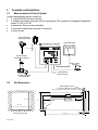
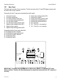
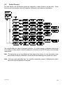
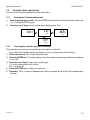
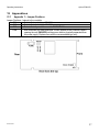
Download EUTECH INSTRUMENTS ALPHA DO 1000 DISSOLVED OXYGEN CONTROLLERTRANSMITTER Instruction manual
Transcript
Instruction Manual αlpha-CON1000 Conductivity Controller/Transmitter Conductivity Controller α lpha CON1000 MEAS 8.08 25.0 mS o C ATC ALARM REL A REL B CAL REL A AUTO MANU ENTER REL B ESC 68X216802 Preface This manual serves to explain the use of the αlpha-CON1000 series Conductivity controller/transmitter. The manual functions in two ways: firstly as a step by step guide to help the user operate the instrument. Secondly, it serves as a handy reference guide. This instruction manual is written to cover as many anticipated applications of the αlpha-CON1000 Conductivity controller/transmitter. If you have doubts in the use of the instrument, please do not hesitate to contact the nearest Eutech Instruments’ Authorised Distributor. The information presented in this manual is subject to change without notice as improvements are made, and does not represent a commitment on part of Eutech Instruments Pte Ltd. Eutech Instruments cannot accept any responsibility for damage or malfunction of the unit due to improper use of the instrument. Copyright 1998 Eutech Instruments Pte Ltd. Version 1.0. All rights reserved. EUTECH INSTRUMENTS PTE LTD Blk 55 Ayer Rajah Crescent, #04-16/24, Singapore 139 949. Tel: (65) 778 6876; Fax: (65) 773 0836 TABLE OF CONTENTS 1 Introduction ........................................................................................................ 3 1.1 Description of Unit ................................................................................. 3 1.2 Applications ........................................................................................... 4 2 Assembly and Installation ................................................................................... 5 2.1 Measurement and Control System ........................................................... 5 2.2 Unit Dimensions..................................................................................... 5 3 Electrical Connection ......................................................................................... 6 3.1 Connection Diagram............................................................................... 6 3.2 Back Panel ............................................................................................. 7 4 Overview ......................................................................................................... 8 4.1 Keypad and Display................................................................................ 8 4.2 Function Groups ..................................................................................... 9 4.3 Control Concept ................................................................................... 10 5 MEASUREMENT ............................................................................................ 11 5.1 Display in Measurement mode .............................................................. 11 5.2 Security Codes...................................................................................... 11 6 Calibration Mode............................................................................................. 14 6.1 Conductivity Calibration....................................................................... 14 7 ADVANCED SET-UP MODE............................................................................. 15 7.1 Temperature Coefficient sub-function ................................................... 15 7.2 Temperature calibration (ATC mode only) ............................................ 16 7.3 Control Relay A/Control Relay B (SP1/SP2) sub-function..................... 17 68X216802 2 Operating Instructions αlpha-CON1000 7.4 Controller (Cntr) sub-function............................................................... 19 7.5 Measurement Range sub-function ......................................................... 20 7.6 Current Output (rng) sub-function......................................................... 21 7.7 Configuration (ConF) sub-function ....................................................... 22 7.8 Calibration (CAL) sub-function ............................................................ 23 8 Auto/Manual Mode .......................................................................................... 24 8.1 Auto mode (mode after switch-on) ........................................................ 24 8.2 Manual mode........................................................................................ 24 9 Technical Specifications............................................................................... 25 10 Accessories Assembly Accessories.................................................................... 26 11 General Information......................................................................................... 26 11.1 Warranty .............................................................................................. 26 11.2 Packaging............................................................................................. 26 11.3 Return of Goods ................................................................................... 26 11.4 Guidelines for Returning Unit for Repair............................................... 26 12 Appendices............................................................................................... 27 12.1 Appendix 1 – Jumper Positions ............................................................. 27 12.2 Appendix 2 – Measurement Ranges available in the Controller.............. 28 12.3 Appendix 3 – Conductivity at Related Temperature Coefficients (25oC) 28 12.4 Appendix 4 – Conductivity of Various Aqueous Solutions at 25oC ........ 30 12.5 Appendix 5 - Simple Explanation on the Function of Hysteresis ............ 31 12.6 Appendix 6 – General Instructions Concerning Controller Setting ......... 32 1 Introduction 1.1 Description of Unit Thank you for purchasing Eutech’s ¼ DIN alpha-1000 series Conductivity process controllers. This unit is used for measuring the Conductivity of a solution, either in micro-Siemens or milli-Siemens, one at a time, and the operational mode is switchable from the menu. You can use this unit to measure Conductivity with limit control. This controller has many user-friendly and safety features which include: • • • • • • • • Menu-driven program that simplifies set-up Ten ranges of Conductivity measurements-software selectable (Appendix 2). Built-in memory backup to ensure that calibration data and other information are not erased if power supply fails Automatic temperature compensation (ATC) with Pt100 or Pt 1000 Manual temperature compensation with independent setting for calibration and process temperature Temperature coefficient variable between 0.00 to 10.00 % per oC. Separate pure water compensation curve stored in memory. Reference temperature at 25oC. 0 to 1999 second time delay adjustment on all relays – minimise false alarms Separately adjustable high and low set point hysteresis (dead bands) prevent chattering of relays around the set points 68X216802 3 • • • • • • • Three control modes: limit, proportional pulse length or proportional pulse frequency Large dual display LCD for easy reading with clear multiple annunciators, alarm status and operational message annunciators Two switching contacts as set-point triggering relays and an alarm output relay Separate alarm relay alerts you when set points have exceeded the limits and if the Pt100/Pt1000 wires are broken or disconnected during the ATC function Hold function freezes output current (0/4...20mA) and releases control relays LED indicators signal control activities to monitor controller status from a distance Protection against electromagnetic interference - galvanically isolated 0/4..20mA output provides safety for data logging and control purposes 1.2 Applications Use this controller in panel mounted enclosures for applications in water treatment and demineralization, waste water treatment and neutralization processes. 68X216802 4 2 Assembly and Installation 2.1 Measurement and Control System A typical measurement system consists of: • a αlpha-CON1000 process controller • a suitable Conductivity electrode with the appropriate Cell constant and integrated temperature sensor Pt 1000 or Pt 100, • an immersion, flow or process assembly • a final control element such as pump or valve and • a chart recorder. Flow Assembly to Dosing Pumps lpha-CON1000 Controller Chart Recorder Pt100/Pt1000 Temperature Sensor Alarm / Siren System Power Mains (220/110 VAC) Process Assembly with Electrode 2.2 Unit Dimensions Flat Gasket (1mm) (To be Inserted By Customer) Note: The Taped Corners Have to Be On Top 92 + 0.5 96 92 56 32 92 + 0.5 max. 45 Mounting Cut-Out 68X216802 max. 175 The field-tested control panel housing is 96 x 96 mm; with protection class IP 54 (front). Electrical Connection 3.1 Connection Diagram O CON O S/ S/ V 18 19 2 0 2 1 2 2 PE/S Pt 1000/100 Signa l Input Conductivity Relay A Po wer M ains Relay B Hold Input Alarm Sign al Ou tpu t CON mA + 3 2 1 4 5 6 7 8 9 10 11 12 13 14 15 16 17 PE/S AC: L N PE * ) indicated contact positions are for currentless conditions 68X216802 6 
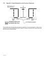
αlpha-CON1000 Operating Instructions 3.2 Back Panel The back panel consists of two connectors. The first connector is the 17-way PCB edge connector and the other is the 5-way connector. Connection for the 17-way screw terminals (from left to right): 1. 2. 3. 4. 5. 6. 7. 8. 9. AC mains live wire AC mains neutral wire AC mains protective earth wire Low set relay resting position (NC) Low set relay common Low set relay working position (NO) High set relay resting position (NC) High set relay common High set relay working position (NO) 10. 11. 12. 13. 14. 15. 16. 17. Alarm relay resting position (NO) Alarm relay common Alarm relay working position (NC) Hold function switch terminal 1 Hold function switch terminal 2 No connection 0/4 - 20 mA for -ve connection 0/4 - 20 mA for +ve connection Connections for the 5-way screw terminals: 18. Pt1000/Pt100 lead 1 terminal 19. Pt1000/Pt100 sense lead terminal 20. Pt1000/Pt100 lead 2 terminal 21. Conductivity lead 1 22. Conductivity lead 2 Pt100/ Pt1000 cell FUSE 250VAC 63mA (F) J2 RELAY2 ALARM HOLD NC - N + RELAY1 L PE IMPORTANT: The Alarm relay functions as an “Active Low” device i.e. it switches OFF under Alarm condition. Therefore the Alarm display device should be connected to the ‘NC’ contacts of the relay. 68X216802 7 4 Overview 4.1 Keypad and Display 4.1.1 Keypad • Perform rapid calibration • • • • Allows entry to Set up mode Select individual functions within the function group of Set up mode Store input data in the Set up mode Start calibration in the calibration mode • Select various function groups in the Set up mode. • Set parameters and numerical values in sub functions of Set up mode If pressed continuously, the setting speed increases • Control the relays in the MANUAL function • Return to the Measurement mode when both keys are pressed together • Switch between AUTO and MANUAL relay operation using a code • Display limit set-point values for the switch contacts in AUTO relay operation mode • Switch between RELAY A and RELAY B in MANUAL relay operation mode 4.1.2 Display The LCD display features two numerical displays that show status messages and measured values for easy, quick reference. The display provides short-text information for setting parameters and configuration. READY 8 • • • • • • HOLD: Relay position and current output are frozen SETUP: Set-up mode of function groups µS mS MEAS: Measurement mode CAL: Calibration mode of Conductivity C READY: Comes on after a successful calibration ATC ATC: Comes on in the ATC mode. Disappears in the Manual temperature Compensation mode. “ATC” flashes if the temperature probe is faulty in its ATC mode • Range No.: Indicates the measurement range selected • Display for RELAY A/B. Green LED indicates measured value within limit while RED LED indicates measured value outside limit. HOLD SETUP MEAS CAL -8.8.8.8 1.8.8.8 o • Alarm display if limit value overshoot or the ATC connection is broken. 68X216802 αlpha-CON1000 Operating Instructions 4.2 Function Groups The main function and sub-function groups are organised in a matrix format for configuration and selection of parameters. The main function groups are: 1) 2) 3) 4) 5) 6) 7) 8) Temperature Coefficient settings (tC) Temperature Measurement / compensation settings (SEt oC) Control relay 1 configuration (SP1) Control relay 2 configuration (SP2) Control type (Cntr) Current output (rng) Configuration (ConF) Calibration (CAL dO) HOLD SETUP tc HOLD SETUP HOLD SETUP SEt HOLD SETUP CAL ConF SP2 SP 1 o C HOLD SETUP HOLD SETUP HOLD SETUP HOLD SETUP rng Cntr Con The set-up parameters can be viewed or changed by entering a security code. See Section 5.2 for security code information. 4.2.1 How to view operating parameters without access to change them: a) Press the ENTER key. The display will prompt the user to enter a security code (S.Cd). Leave the security code at “000” (do not enter a security code). S.Cd b) Press ENTER key again. This allows you only to view (not change) any sub-functions’ settings. c) Press the ∆ or ∇ keys to scroll through the sub-functions. Press the ENTER key at a particular sub-function to view in detail. Press the ENTER key to return to the sub-function menu. Press the ∆ and ∇ keys simultaneously (as an Escape key) at any time to return to the Measurement mode. 000 d) e) f) Note: To simplify operations, the controller will not display parameters that are not relevant to a particular sub-function. For example: If the user set the controller for Limit control, it will not display pulse length/frequency settings. 68X216802 9 4.3 Control Concept The main function and sub-function groups are organised in a matrix format as shown below. These functions can be accessed via the front keypad for configuration and selection of parameters. The controller offers two levels of password protection: (1) for direct access to calibration function and (2) for setting or editing specific controller parameters or functions in the SETUP mode to suit individual requirements. Note: The passwords are not user-defined and have been set by factory. It is very important to keep these passwords strictly confidential to avoid unauthorised tampering of the system at all times. Note: If the user reads parameters only, the controller automatically reverts to Measurement mode if none of the keys is pressed for 30 seconds. 68X216802 10 αlpha-CON1000 Operating Instructions 5 MEASUREMENT 5.1 Display in Measurement mode When the controller is initially powered on, it automatically enters into the Measurement mode after the large dual LCD displays all segments briefly. The upper display shows the measured Conductivity value, while the lower display shows the temperature value. Annunciators at the right side of the display indicate whether the controller is set for µS or mS measurement. Similarly annunciators or icons at the top or left side of the display shows the current status of controller, e.g. “HOLD”, “SETUP”, “MEAS”, “CAL”, “READY”, etc. 5.1.1 Check electrode performance To read current electrode slope and offset values without changing them: 1) Press the CAL key followed by the ENTER key without adjusting the security code (leave code at “000”). The upper display shows the condition of the probe. The lower display reading shows the temperature reading. Note: If security code is changed to a value other than “000”, pressing the ENTER key will return to the Measurement mode, without displaying electrode information. 2) Press the ENTER key a second time to return to Measurement mode. 5.1.2 Checking set points To read current set point values without changing them: Press the RELAY Selection (Rel A / Rel B) key. The upper display shows the set point for Relay A; the lower display shows “SP1”. After two seconds the upper display shows the set-point value for Relay B; the lower display shows “SP2”. After an additional two seconds, the controller returns to the Measurement mode. 5.2 Security Codes This controller has two levels of security protection with separate security codes. The first level allows entry into the Calibration mode: security code = 11; the second allows entry into the SETUP mode: security code = 22. The security codes protects the controller from unauthorised tampering of its current setting. The parameters cannot be changed unless the security code is entered. 5.2.1 How to enter and change parameters in Calibration mode 1) Press the CAL key. The upper display shows “000” and the lower display shows “C.Cd” to prompt the user to enter the Calibration security code. 11 C.Cd 2) Press the ∆ or ∇ keys to scroll upper display to Calibration security code “11”. 3) Press the ENTER key. The display shows “CAL CON”. 4) Press ENTER key again to begin calibration. Refer to Section 6 for full details on calibration. 5) Press the ∆ and ∇ keys simultaneously (escape) to return to the Measurement mode. 68X216802 11 NOTE: To view (not change) the SETUP parameters, push the ENTER key when the security code reads “000”. 68X216802 12 Operating Instructions αlpha-CON1000 5.2.1.1 Clearing the Calibration security code from the display The calibration security code automatically resets from “11” to “000” after you return to Measurement mode, so you do not need to clear the security code from the display. 5.2.2 How to enter and change parameters in Advanced Setup mode 1) Press the ENTER key once. The upper display shows “000” and the lower display shows “S.Cd” to prompt you to enter the Advanced Setup security code. 2) Press the ∆ or ∇ keys to scroll the display to Setup security code “22”. NOTE: Pressing the ENTER key at a value other than “22” causes the controller to revert to the Measurement mode. 3) Press the ENTER key. 4) The upper display reads “tc”. 5) You are now in the Advanced Setup mode. See Section 7 for complete instructions. To return to Measurement mode, press the ∆ and ∇ keys simultaneously (escape). NOTE: If you want to view (not change) set up parameters, push the ENTER key when the security code reads “000”. 5.2.2.1 Clearing the Advanced Setup security code from the display After you have entered the security code and returned to the Measurement mode, the security code “22” still appears on the display whenever you press the ENTER key. To conceal the security code, you must manually reset the code. To clear the Advanced Setup security code from the display: 1) Press the ENTER key in the Measurement mode. 2) Set to any security code (not 11 or 22) and complete by pressing ENTER. NOTE: When you enter the Calibration mode with code “11” or Advanced Setup mode with security code “22”, the unit automatically enters into the HOLD mode until you return back to Measurement mode. The HOLD annunciator is displayed at the upper left of the display. While on HOLD, the current output is frozen and set point relays are deactivated. 68X216802 13 6 Calibration Mode You can reach the Calibration mode directly from the Measurement mode by pressing the CAL key and entering the Calibration security code. You can also reach the Calibration mode from the Advanced Setup mode. 6.1 Conductivity Calibration Calibration is always carried out in the specific range selected. The Conductivity Controller allows a one-point calibration. HOLD SETUP CAL 6 Con HOLD CAL 100.0 100.0 6 HOLD CAL 1413 6 25.0 HOLD µS o C ATC CAL 100.0 100.0 6 % CEL CEL % 1) Enter Calibration mode. While in the Measurement mode, push the CAL key and scroll to Calibration code “11”. Push the ENTER key again. The upper display reads “CAL” and the lower display shows “Con”. 2) Press the ENTER key. The controller displays the status of the Cell resulting from the previous calibration. Press the ENTER key once again to carry out calibration. 3) Immerse the Conductivity cell in a suitable standard solution, whose value is within the measurement range selected in the controller. Agitate the Cell in the solution to remove any trapped air-bubbles. 4) Once the reading has stabilized, use the ∆ or ∇ keys to adjust the measured value to that of the standard solution. Press the ENTER key to accept the value and the controller displays the revised condition of the probe. Note: if the percentage difference between the measured value and the standard solution is greater than 40%, the controller will not accept the calibration. Change the Cell. 5) Press the ENTER key. If you entered the calibration mode using the CAL key, the controller will return to the Measurement mode. If you entered the calibration mode from the Advanced Set-up mode, the controller will return to the sub-function menu. Note: If there is a calibration error, the controller displays “ERR”. If this happens, push both the ∆ and ∇ keys (escape) to restart the calibration beginning from step 1. Note: When calibrating with manual temperature compensation, the controller automatically changes from the preset process temperature to the calibration temperature. After leaving the Calibration mode, the controller switches back to process temperature (for setting the calibration temperature and the process temperature, see section 7.4.3). 68X216802 7 7.1 ADVANCED SET-UP MODE Temperature Coefficient sub-function This sub-function allows you to select the correct temperature coefficient for optimum operations. For applications in the pure water or ultr-pure water industries, simply select the “Pur” temperature coefficient option. For all other applications, select “Lin” temperature coefficient. The controller allows further input of temperature coefficient values, independently for the process and for the calibrating solutions. Default is at 2.10 %. HOLD SETUP HOLD SETUP HOLD SETUP Lin tc tC HOLD SETUP 2.10 P.tC % ATC 2.10 C.tC % ATC HOLD SETUP Pur tC 7.1.1 Selecting Pure-water or Linear Temperature Coefficient HOLD SETUP tc HOLD SETUP Lin tC HOLD SETUP 2.10 % P.tC ATC HOLD SETUP 68X216802 2.10 % C.tC ATC 1) Enter Advanced set-up mode. Push the ENTER key and scroll to Advanced Set-up security code “22”. Push the ENTER key again. Controller displays “Lin” in the upper display and “tC” in the lower display. 2) Press the ∆ or ∇ keys to select between “Pur” and “Lin” temperature coefficients. If “Pur” tC is be selected, press the ENTER key and controller goes back to “tC”. If “Lin” tC is selcted, press the ENTER key and proceed to step 3. 3) The upper display shows “2.10%”, while the lower display show “P.tC”. This option allows you to input the Process Temperature coefficient, from 0 to 10%. Default is 2.10%. Use the ∆ or ∇ keys to enter the required temperature coefficient value. 4) Press the ENTER key. Next, enter the calibration solution temperature coefficient value, from 0 to 10%. Default is 2.10%. 5) Press the ∆ or ∇ keys to input the desired calibration solution temperature coefficient. 6) Press the ENTER key to accept the value. 7) Continue with additional Advance setup procedures or return to Measurement mode by pressing the ∆ and ∇ keys (escape) simultaneously. 7.2 Temperature calibration (ATC mode only) HOLD SETUP on Atc HOLD SETUP 0.0 o C 25.0 7.2.1 ATC 1) Select “ATC on” as described above in Section 7.4.1. 2) Press the ENTER key. The upper display indicates the current temperature offset. The current measured temperature is shown in the lower display. 3) Compare the current measured temperature on the controller display to a thermometer known to be accurate. Note down the correct temperature value. 4) Press the ∆ or ∇ keys to scroll the lower display to match the correct value. The upper display will now show the offset value. You can offset temperature up to ± 5 oC. 5) Press the ENTER key to confirm your selection. 6) Continue with additional Advanced Set-up procedures, or return to the Measurement mode by pressing the ∆ and ∇ keys (escape) simultaneously. Setting manual temperature compensation Note: This parameter is blanked out when the controller is set for HOLD SETUP ATC operation. For manual temperature compensation, you can set two different temperatures: process and calibration. This allows calibration at a Atc temperature other than your process temperature. Example: setting a calibration temperature of 25 oC lets you calibrate using standard buffer solutions at 25 oC, even if your process temperature is a HOLD SETUP different temperature. 1) Select “ATC oFF” as described above in section 7.4.1 2) Press the ENTER key. The upper display shows the current P.C process temperature and the lower display shows “P.oC” to indicate process temperature. oFF 25.0 HOLD SETUP 25.0 C.C 5) 6) 7) 3) Press the ∆ or ∇ keys to adjust the process temperature value. You can adjust the value from –9.9 to 125 oC. 4) After you set the process temperature value, press the ENTER key. The upper display shows the current calibration temperature and the lower display shows “C.oC” to indicate calibration temperature. Press the ∆ or ∇ keys to adjust the calibration temperature value. You can adjust this value from –9.9 to 125 oC. Press the ENTER key to confirm your selection. Continue with additional Advanced Set-up procedures, or return to Measurement mode by pressing the ∆ and ∇ keys (escape) simultaneously. 68X216802 αlpha-CON1000 Operating Instructions 7.3 Control Relay A/Control Relay B (SP1/SP2) sub-function The SP1 option sets the operating parameters for Relay A; and SP2 for relay B. Since these groups have the same set-up parameters, they are described together. HOLD SETUP HOLD SETUP SP 1 7.3.1 HOLD SETUP 100 SP 1 HOLD SETUP Lo SP 1 HOLD SETUP 20 HYS HOLD SETUP 0 On.d 0 Of.d Entering the Set point 1 (Set point 2) sub-function 1) Enter Advanced Set-up mode. Push the ENTER key and HOLD SETUP scroll to Advanced Set-up security code “22”. Push the ENTER key again. SP 1 2) Press the ∆ or ∇ keys to scroll until the upper display shows SP1 (SP2). HOLD SETUP 100 µS SP 1 HOLD SETUP Lo SP 1 7.3.2 Selecting the set point values This lets you choose the value that will cause your controller to activate (Default: SP1 = 6.20mg/l; SP2 = 4.00mg/l). 1) Follow directions in 7.5.1 to enter Control Relay mode. If you are in this mode, skip to step 2. 2) Press the ENTER key. The upper display shows the current set point value and the lower display shows SP1 (SP2). 3) Press the ∆ or ∇ keys to select your value for Set point 1 (Set point 2). Your controller will activate at the value you select. 4) Press the ENTER key to confirm your selection. 5) Proceed to 7.5.3, or return to Measurement mode by pressing the ∆ and ∇ keys simultaneously (escape). 7.3.3 Choosing High or Low set points Select a low set point to activate controller when the dissolved oxygen value undershoots the low set point; select a high set point to activate controller when the value overshoots the high set point. Using both SP1 and SP2, you can select lo/lo, lo/hi, hi/lo, or hi/hi set points (Default: SP1 = Lo; SP2 = Lo). 1) Follow directions in 7.5.2 to enter Control Relay mode. 2) Press the ENTER key. Scroll with the ∆ or ∇ keys until the upper display shows Lo or Hi (for low or high set point) and the lower display shows SP1 (SP2). 3) 4) Press the ∆ or ∇ keys to select low (lo) or high (hi) set point for SP1 (SP2). Press the ENTER key to confirm your selection. 5) Proceed to 7.5.4, or return Measurement mode by pressing the ∆ and ∇ keys simultaneously (escape). 7.3.4 Selecting a hysteresis (dead band) value (0.1 to 1.0 mg/l or 1 to 10%) Hysteresis prevents rapid contact switching if your value is fluctuating near the set point. It does this by overshooting the set point value to a specified hysteresis value (default is 0.2 mg/l or 2.5%). You can set the hysteresis value from 0.1 to 10 mg/l, 0.1 to 10 ppm or 1 to 10%. 68X216802 17 Example: You have set your set point 1 (Lo) at 6.00 µS and your hysteresis limit value is at 0.50 µS. If your measured value undershoots the low set point of 6.00 µS, the controller’s relay activates, which in turn activates an external device such as a pump or valve. The actions of the external device will cause the value to rise above 6.00 µS. When the value has increased to 6.50 µS, the relay, and hence the pump will switch off. HOLD SETUP 1) Follow directions in 7.5.3 to enter Control Relay mode. 20 HYS 4) µS 2) Press the ENTER key. Scroll with the ∆ or ∇ keys until the upper display shows the hysteresis (dead band) value and the lower display shows “HYS”. 3) Press the ∆ or ∇ keys to enter your hysteresis value for Set point 1 (Set point 2). Your controller will activate at the value you select. Note: All settings for SP1 and SP2 are completely independent of each other. Press the ENTER key to confirm your selection. Proceed to 7.5.5, or return to Measurement mode by pressing the ∆ and ∇ keys simultaneously (escape). NOTE: Please refer to Appendix 3 for a graphical representation of the Hysteresis. 5) 7.3.5 Setting an on-delay time lag You can set as time delay for each relay, which stops the relay from switching on the moment the set point is exceeded. This controller lets you set a 0 to 1999 seconds time delay before the relay activates. 1) Follow directions in 7.5.4 to enter Control Relay mode. HOLD SETUP 0 On.d 4) 5) 2) Press the ENTER key. Scroll with the ∆ and ∇ keys until the upper display shows “0” time and the lower display shows “On.d”. 3) Press the ∆ or ∇ keys to enter on-delay time for Set point 1 (Set point 2). The controller will delay activation for the number of seconds (0 to 1999) you select. Press the ENTER key to confirm your selection. Proceed to 7.5.6, or return to Measurement mode by pressing the ∆ and ∇ keys simultaneously (escape). 7.3.6 Setting an off-delay time lag You can set as time delay for each relay, which stops the relay from switching off the moment the value reached the set point and hysteresis. This controller lets you set a 0 to 1999 seconds time delay before your relay deactivates. 1) Follow directions in 7.5.5 to enter Control Relay mode. HOLD SETUP 0 2) Press the ENTER key. Scroll with the ∆ or ∇ keys until the upper display shows “0” time and the lower display shows “OF.d”. OF.d 5) 3) Press the ∆ or ∇ keys to enter on-delay time for Set point 1 (Set point 2). Your controller will delay activation for the number of seconds (0 to 1999) you select. 4) Press the ENTER key to confirm your selection. Continue with Advanced Set-up mode procedures, or return to Measurement mode by pressing the ∆ and ∇ keys simultaneously (escape). 68X216802 18 αlpha-CON1000 Operating Instructions 7.4 Controller (Cntr) sub-function You can set the controller’s parameters in this sub-function. 7.4.1 Entering the Controller sub-function 1) Enter Advanced Set-up mode. Push the ENTER key and scroll to Advanced set-up security code “22”. Push the ENTER key again. 2) Press the ∆ or ∇ keys to scroll until the upper display shows “Cntr”. HOLD SETUP Cntr HOLD SETUP L.Ct tyP HOLD SETUP dEEn rEL HOLD SETUP oFF tyP 7.4.2 Choosing the controller type (limit or monitor) This mode lets you choose your controller type: limit control or control off. - Use control off to operate controller as a monitor only or to prevent relays from switching. 1) Follow directions in 7.6.1 to enter Controller mode. 2) Press the ENTER key. The upper display shows the current controller type and the lower display shows “tyP”. 3) 4) Press the ∆ or ∇ keys to select your controller type. L.Ct = limit value pickup (on/off control). oFF = controller off. Press the ENTER key to confirm your selection. 5) Proceed to 7.6.3, or return to Measurement mode by pressing the ∆ and ∇ keys simultaneously (escape). 68X216802 19 7.4.3 Choosing break/make contact relay type Note: If the controller type “oFF” is set, the parameters listed in 7.5.3, 7.5.4, 7.5.5 and 7.5.6 are blanked out. This mode lets you determine the relay-state under Non-Alarm condition – dEEN (de-energised) or EN (energised). 1) Follow directions in 7.6.2 to enter Controller mode. HOLD SETUP 2) Press the ENTER key. Scroll until the lower display shows “rEL” and the upper display shows the current selection (de-energised = rEL dEEN or energised = EN). dEEn HOLD SETUP En rEL 3) Press the ∆ or ∇ keys to choose de-energised or energised relay state. 4) Press the ENTER key to confirm your selection. 5) Continue with Advanced Set-up mode procedures, or return to Measurement mode by pressing the ∆ and ∇ keys simultaneously (escape). 7.5 Measurement Range sub-function In this sub-function, the appropriate range is selected with the appropriate cell constant. HOLD SETUP rng 7.5.1 Selecting the Measuring Range sub-function 1) Enter Advanced Set-up mode. Push the ENTER key and scroll to Advanced Set-up security code “22”. Push the ENTER key again. 2) Press the ∆ or ∇ keys to scroll until the upper display shows “rng”. 3) Press the ENTER key. The upper display shows the maximum HOLD SETUP measurement range, while the lower display shows the Cell constant. In µS the lower left-corner of the LCD, the number corresponding to the respective range is displayed. 4) Press the ∆ or ∇ keys to select the correct range. (Please refer to 4 Appendix 2 for the full list of measurement ranges). 5) Proceed to 7.8 to set current output or return to Measurement mode by pressing the ∆ and 200. 200.0 0.1 ∇ keys simultaneously (escape). 68X216802 αlpha-CON1000 Operating Instructions 7.6 Current Output (rng) sub-function This sub-function lets you set the transmitter current output range of this unit. The difference between the upper and lower range has to be a minimum of 20% of Full Scale, anywhere on the scale. 7.6.1 Entering current output sub-function HOLD SETUP 1) Enter Advanced Set-up mode. Push the ENTER key and scroll to Advanced Set-up security code “22”. Push the ENTER key again. rng 2) Press the ∆ or ∇ keys to scroll until the upper display shows “rng”. Press ENTER. 3) Measurement range selection. Please refer to 7.7. Press ENTER to proceed to current output sub-function (7.8.2) HOLD SETUP 4 200.0 0.1 µS 7.6.2 Choosing the output type This parameter lets you choose between 0-20 mA or 4-20 mA output. 1) Follow directions in 7.8.1 to enter Current Output mode. HOLD SETUP 4-20 out 4 HOLD SETUP 0.00 µS r.4 4 2) Press the ENTER key. Scroll with the ∆ or ∇ keys until the upper display shows the output type (0-20 or 4-20), and the lower display shows “out”. 3) Press the ∆ or ∇ keys to select your output type: 0-20 or 4-20 mA. 4) Press the ENTER key to confirm your selection. 5) Proceed to 7.8.3, or return to Measurement mode by pressing the ∆ and ∇ keys simultaneously (escape). HOLD SETUP 200.0 7.6.3 Selecting Conductivity value at 0(4)mA This parameter lets you choose the conductivity value at which the r.20 transmitter output will be 0(4) mA. 4 Follow directions in 7.8.2 to enter Current Output mode. µS 1) Press the ENTER key. Scroll with the ∆ or ∇ keys until the upper display shows a conductivity value and the lower display shows “r.0(4)”. 2) Press the ∆ or ∇ keys to select the required conductivity value to be equivalent to 0(4) mA (0.00 to 80.0 % F.S.; Default is 0% F.S.). Press the ENTER key to confirm your selection. Press the ENTER key to return to Advanced Set-up mode, or return to Measurement mode by pressing the ∆ and ∇ keys simultaneously (escape). 3) 4) 7.6.4 Selecting Conductivity value at 20mA This parameter lets you choose the conductivity value at which the transmitter output will be 20mA. 5) Follow directions in 7.8.3 to enter Current Output mode. 6) Press the ENTER key. Scroll with the ∆ or ∇ keys until the upper display shows a conductivity value and the lower display shows “r.20”. 7) Press the ∆ or ∇ keys to select the required conductivity value to be equivalent to 20 mA (20.0 to 100.0% F.S.; Default is 100% F.S.). 68X216802 21 8) 9) Press the ENTER key to confirm your selection. Press the ENTER key to return to Advanced Set-up mode, or return to Measurement mode by pressing the ∆ and ∇ keys simultaneously (escape). HOLD SETUP COnf HOLD SETUP HOLD SETUP 0 ALd Stdy HOLD SETUP 0.0 ALC L.Ad HOLD SETUP no 7.7 Configuration (ConF) sub-function dEF This group of parameters lets you configure the controller to suit your requirements. 7.7.1 Entering the Configuration sub-function 1) Enter Advanced Set-up mode. Push the ENTER key and scroll to Advanced Set-up security code “22”. Push the ENTER key again. 2) Press the ∆ or ∇ keys to scroll until the upper display shows “ConF”. 7.7.2 Selecting the alarm time lag This parameter group lets you select a period of time before the alarm activates when your set point has been overshot. You can select from 0 to 1999 seconds. 1) Follow directions in 7.9.1 to enter Configuration mode. HOLD SETUP 30 AL.d 4) 5) 2) Press the ENTER key. Scroll with the ∆ or ∇ keys until the upper display shows a numerical value (in seconds) and the lower display shows “AL.d”. 3) Press the ∆ or ∇ keys to select how long of an alarm delay (0 to 1999 seconds) you want. Press the ENTER key to confirm your selection. Proceed to 7.9.3, or return to Measurement mode by pressing the ∆ and ∇ keys simultaneously (escape). 7.7.3 Selecting steady or pulse contact for the alarm relay This parameter group lets you select whether the alarm contact will operate as a steady contact or a fleeting (single pulse) contact. Pulse contact closing time is 250 millisecond. 68X216802 22 αlpha-CON1000 Operating Instructions 1) HOLD SETUP HOLD SETUP Follow directions in 7.9.2 to enter Configuration mode. AL.C 2) Press the ENTER key. Scroll with the ∆ or ∇ keys until the upper display shows “Stdy” or “FLEt” and lower display shows “AL.C.”. AL.C = alarm contact StdY = steady contact FLEt = fleeting (single pulse) contact FLEt 3) Press the ∆ or ∇ keys to select steady or pulse contact. 4) Press the ENTER key to confirm your selection. 5) Proceed to 7.9.4, or return to Measurement mode by pressing the ∆ and ∇ keys simultaneously (escape). Stdy AL.C 7.7.4 Input Line Resistance Adjust This function compensates for the line resistance of the cable to its cell. 1) Follow directions in 7.9.3 to enter Configuration mode. HOLD SETUP 0.0 L.Ad 5) 2) Press the ENTER key. Scroll with the ∆ or ∇ keys until the upper display shows “0.0” and lower display shows “L.Ad”. L.Ad = line adjuster resistance (0.0 to 100.0) 3) Press the ∆ or ∇ keys to input the value. 4) Press the ENTER key to confirm your selection. Proceed to 7.9.5, or return to Measurement mode by pressing the ∆ and ∇ keys simultaneously (escape). 7.7.5 Reverting to factory default settings Use this parameter to reset all settings to factory default. Changing from “no” to “YES” and pressing the ENTER key resets all settings to factory default. WARNING: If you select yes, all the settings you have made will be HOLD SETUP overwritten as a result! 1) Follow directions in 7.9.4 to enter Configuration mode. no dEF 3) 4) 2) Press the ENTER key. Scroll with the ∆ or ∇ keys until the upper display shows “no” or “YES”, and the lower display shows “deF” (default). Press the ∆ or ∇ keys to select no or yes. Selecting “YES” and pressing the ENTER key will overwrite all setting you have made and automatically return you to Measurement mode. Press the ENTER key to confirm your selection and to return to Advanced Set-up mode, or return to Measurement mode by pressing the ∆ and ∇ keys simultaneously (escape). 7.8 Calibration (CAL) sub-function The calibration procedure in Advanced Set-up mode is identical to the procedure in the Calibration mode. The only difference is that the controller will revert back to Set-up mode (instead of Measurement mode) after calibration is completed. 68X216802 23 7.8.1 Entering Calibration mode from Advanced Set-up mode 1) Enter Advanced Set-up mode. Push the ENTER key and scroll to Advanced Set-up security code “22”. Push the ENTER key again. 2) 3) 8 Press the ∆ or ∇ keys to scroll until the upper display shows “CAL”. See section 6 for complete calibration procedures. Auto/Manual Mode Regardless of the mode, you can control devices connected to Relay A or Relay B from the front panel of this controller. In Automatic mode, the controller’s set point values activate the relays. In Manual mode, you have manual control of the relays so you can prime the pump or check pump status without operating the entire system. 8.1 Auto mode (mode after switch-on) In this mode, the controller set-point values activate the relays. To view the set-point values: 1) Press the RELAY SELECTION (Rel A/Rel B) key. The upper display shows your set-point value for Relay A; the lower display shows “SP1”. 2) After two seconds the upper display shows your set-point value for Relay B; the lower display shows “SP2”. 3) After an additional two seconds the controller will return to Measurement mode. 8.2 Manual mode In this mode, you can manually turn on and off the control devices connected to Relay A or Relay B or both. 1) Press the RELAY CONTROL (auto/manu) key. The upper display shows “000”; the lower display shows “S.Cd” to prompt you to enter the Advanced Set-up code. 2) Press the ∆ or ∇ keys to scroll the upper display until it reads “22”. 3) Press the ENTER key. The manual indicator by the RELAY CONTROL key lights up. Note: Pressing ENTER key at a value other than “22” will cause the controller to revert to Measurement mode, and the relays will remain in automatic mode. 4) Press the RELAY SELECTION key to select either Relay A or Relay B. The LED next to the currently selected relay (A or B) will light. The manual control options are now available. If you selected Limit control: The upper display reads the current measured value. The lower display shows “oFF” or “on” depending on the relay status of the currently selected relay. Press the ∆ or ∇ keys to change the Relay on/off status. The LED indicators at the right of the controller will also change between Red and Green to indicate Relay status. Note: If you wish to manually change the status of both relays, press the RELAY SELECTION key at this point and repeat step 5 for the second relay. This first relay will remain under manual control while you are setting the second relay. 6) Press the RELAY CONTROL key to return to Measurement mode. The relays are now back under automatic control. 5) 68X216802 24 αlpha-CON1000 Operating Instructions 9 Technical Specifications Conductivity Range 0.000 to 1.999 µS/cm 0.00 to 19.99 µS/cm 0.0 to 199.9 µS/cm 0 to 1999 µS/cm 0 to 5000 µS/cm 0.00 to 19.99 mS/cm 0.0 to 199.9 mS/cm Resolution 0.001 µS/cm 0.01 µS/cm 0.1 µS/cm 1 µS/cm 5 µS/cm 0.01 mS/cm 0.1 mS/cm Temperature Resolution Relative Accuracy Sensor Temperature Compensation Set-point and Controller Functions Controller characteristics Pickup / Dropout delay Switching Condutivity hysteresis Contact outputs, controller Switching voltage Switching current Switching power Alarm Functions Function (switchable) Pickup delay Switching voltage Switching current Switching power Electrical Data and Connections Power Requirements Frequency Signal Output Signal Output Load Connection terminal Mains fuse / fine wire fuse EMC Specifications Emissions Susceptibility Environmental Conditions Ambient temp. operating range Relative humidity Mechanical Specifications Dimensions (control panel housing - L x H x W) Weights (control panel housing) Material Insulation (Front / Housing) 68X216802 Default Cell Constant, K 0.01 0.01 0.1 1.0 1.0 1.0 10.0 Optional Cell, K 0.1 1.0 1.0 0-50 oC (Display: -9.9 to 125 oC) 0.1 oC ± 0.5 oC Pt 1000/Pt 100 Auto / manual (reference at 25.0 oC) Limit controller 0 to 1999 sec. 0 to 10% of Full Scale 2 potential-free change-over contacts max. 250 VAC max. 3A max. 600 VA Latching / pulse 0 to 1999 sec. max. 250 VAC max. 3A max. 600 VA 110 / 220 VAC (jumper selectable) 48 to 62 Hz 0/4 to 20 mA, galvanically isolated max. 600 Ω Terminal blocks 5-pole / 17-pole, removable slow-blow 250 V / 100 mA According to EN 50081-1 According to EN 50082-1 0 to 50 oC 10 to 95%, non-condensing 175 x 96 x 96 mm max. 0.7 kg ABS with polycarbonate (front housing) IP 54 / IP 65 25 10 Accessories Assembly Accessories Product Description Code no. Conductivity Cell, up to 20µS; Cell constant, K=0.01 with integrated Pt 100, EC-CS10-0-01S Material SS316 and 25ft cable (open-ended) Conductivity Cell, up to 20µS; Cell constant, K=0.01 with integrated Pt 100, EC-CS10-0-01T Material Titanium and 25ft cable (open-ended) Conductivity Cell, 0.1 - 200µS; Cell constant, K=0.1 with integrated Pt 100, EC-CS10-0-1S Material SS316 and 25ft cable (open-ended) Conductivity Cell, up to 200 mS; Cell constant, K=1.0 with integrated Pt 100, EC-CS10-1-0S Material SS316 and 25ft cable (open-ended) Note: Above Conductivity Cells can withstand a pressure of up to 6 bar. Please ask your authorised distributor or dealer for the prices. 11 General Information 11.1 Warranty Eutech Instruments warrants this product to be free from significant deviations in material and workmanship for a period of one year from the date of purchase. If repair is necessary and has not been the result of abuse or misuse within the warranty period, please return by freight pre-paid and amendment will be made without any charge. Eutech Instruments’ Customer Service Dept. will determine if product problem is due to deviations or customer abuse. Out of warranty products will be repaired on a charge basis. 11.2 Packaging The instrument is packaged in a corrugated box with a warranty card, instruction manual and the following accessories: • 17-way and 5-way (right-angled) terminal block [1 unit each] • side threaded rod with catch [2 units] • receptacle cable lug [1 unit] • rubber gasket [1 unit] 11.3 Return of Goods Authorisation must be obtained from Eutech Instruments’ Customer Service Dept. to issue a RGA (Return of Goods Authorisation) number before returning items for any reason. When applying for authorisation, please include data requiring the reason of return. Items must be carefully packed to prevent damage in shipment and insured against possible damage or loss. Eutech Instruments will not be responsible for any damage resulting from careless or insufficient packing. Warning: Shipping damage as a result of inadequate packaging is the user/distributor’s responsibility, whoever applicable. Please follow the guidelines below before shipment. 11.4 Guidelines for Returning Unit for Repair Use the original packaging material, if possible when shipping the unit for repair. Otherwise wrap it with bubble pack and use a corrugated box for better protection. Include a brief description of any faults suspected for the convenience of Customer Service Dept., if possible. 68X216802 26 Operating Instructions αlpha-CON1000 12 Appendices 12.1 Appendix 1 – Jumper Positions Jumper Positions - Internal to the controller JP 1 Selects the input voltage 220 VAC. JP 2 Selects the input voltage 110 VAC. JP 3 Selects the temperature sensor for Pt1000/Pt100 Fuse Note that there is a fuse (slow-blow 100mA) internal to the controller. Before opening the unit, ENSURE that the power cable is physically separated from the power supply. Replace fuse with the recommended type only. 68X216802 27 12.2 Appendix 2 – Measurement Ranges available in the Controller Range No. 1 2 3 4 5 6 7 8 9 0 12.3 Range 0.000 – 1.999 µS 0.00 – 19.99 µS 0.00 – 19.99 µS 0.0 – 199.9 µS 0.0 – 199.9 µS 0 – 1999 µS 0 – 5000 µS 0.00 – 19.99 mS 0.0 – 199.9 mS 0.0 – 199.9 mS Resolution 0.001 µS 0.01 µS 0.01 µS 0.1 µS 0.1 µS 1 µS 5 µS 0.01 mS 0.1 mS 0.1 mS Appendix 3 – Conductivity at Related Temperature Coefficients (25oC) Substance Concentration wt % Conductivity 10-4 S/cm NaOH 5 10 15 20 30 40 25.2 29.4 33.6 42.0 0.10 1.60 4.01 8.03 16.15 30.5 1.5 4.8 24.5 6.2 12.4 31.0 49.6 62.0 1969 3124 3463 3270 2022 1164 5403 5434 5221 4212 2.51 8.67 10.95 10.38 6.32 1.93 198 593 2832 3123 5418 7819 6341 4964 KOH (15oC) NH3 (15oC) HF HNO3 68X216802 Default cell K 0.01 0.01 0.1 0.1 1.0 1.0 1.0 1.0 10.0 1.0 Conductivity Coefficient 2.01 2.17 2.49 2.99 4.50 6.48 2.09 2.21 2.36 2.83 2.46 2.38 2.50 2.62 3.01 7.20 6.66 5.83 1.47 1.42 1.39 1.57 1.57 28 Substance Concentration wt % Conductivity 10-4 S/cm H3PO4 (15oC) 10 20 40 45 50 5 10 15 20 25 5 10 15 5 10 20 30 40 5 10 20 40 50 60 80 100.14 5 10 20 30 1 10 15 20 30 40 5 10 15 5 10 15 20 566 1129 2070 2087 2073 672 1211 1642 1957 2153 409 687 886 1969 3124 3463 662 5152 2085 3915 6527 6800 54055 3726 1105 187 109 189 320 421 5.84 15.26 16.19 16.05 14.01 10.81 456 705 836 690 1359 2020 2677 NaCl Na2SO4 HCl H2SO4 CuSO4 CH3COOH Na2CO3 KCl 68X216802 Conductivity Coefficient 1.04 1.14 1.50 1.61 1.74 2.17 2.14 2.12 2.16 2.27 2.36 2.49 2.56 1.58 1.56 1.54 1.52 1.21 1.28 1.45 1.78 1.93 2.13 3.49 0.30 2.13 2.16 2.18 2.31 1.69 1.74 1.79 1.86 1.95 2.52 2.71 2.94 2.01 1.88 1.79 1.68 Substance KBr (15oC) KCN (15oC) NH4Cl (NH4)2SO4 12.4 25 Concentration wt % 2810 Conductivity 10-4 S/cm 1.66 Conductivity Coefficient 5 10 20 3.25 6.5 5 10 15 20 25 5 10 20 30 465 928 1907 507 1026 918 1776 2586 3365 4025 552 1010 1779 2292 2.06 1.94 1.77 2.07 1.93 1.98 1.86 1.71 1.61 1.54 2.15 2.03 1.93 1.91 Appendix 4 – Conductivity of Various Aqueous Solutions at 25oC Pure Water Power Plant Boiler Water Distilled Water De-ionized Water De-mineralised Water Mountain Water Drinking Water Waste-water Potable Water Maximum Brackish Water Industrial Process Water Ocean Water 68X216802 Conductivity 0.05 uS/cm 0.05 - 1 uS/cm 0.5 uS/cm 0.1 - 10 uS/cm 1 - 80 uS/cm 10 uS/cm 0.5 - 1 mS/cm 0.9 - 9 mS/cm 1.5 mS/cm 1 - 80 mS/cm 7 - 140 mS/cm 53 mS/cm Resistivity 18 MΩ-cm 1 - 18 MΩ-cm 2 MΩ-cm 0.1 - 10 MΩ-cm 0.01 - 1 MΩ-cm 0.1 MΩ-cm 1-2 MΩ-cm 0.1 - 1 MΩ-cm 0.7 MΩ-cm 0.01 - 1 MΩ-cm rarely stated rarely stated 30 12.5 Appendix 5 - Simple Explanation on the Function of Hysteresis SP1 Set to LO SP2 Set to HI RELAY ON RELAY OFF 10.0 10.5 SP1 FORWARD DIRECTION 100.0 100.5 mS SP2 HYSTERESIS BAND REVERSE DIRECTION The controller relay activates when the set-point is reached. In the reverse direction, it does not deactivate when the value reaches the set-point. Instead, it continues to be active till the value reaches the amount set by the Hysteresis band. 68X216802 12.6 Appendix 6 – General Instructions Concerning Controller Setting MAX Function MIN Function 100 % Yh 50 % 0% - Xw SP 1 Xp = 0 + Xw SP 2 Xp = 0 Control characteristic of P-Controllers as limit value switch 68X216802 32