1
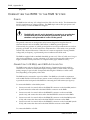
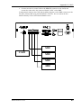
ALESIS RMD REMOTE METER DISPLAY FOR THE M20 PROFESSIONAL 20-BIT DIGITAL RECORDING SYSTEM OWNER’S MANUAL FIRST EDITION VERSION 1.00 APPLIES TO M20 OPERATING SOFTWARE VERSION 1.10 1998 ALESIS CORPORATION RMD, Appendix R RMD MANUAL 1.00 APPENDIX R RMD REMOTE METER DISPLAY This document covers only those aspects unique to the RMD and should be inserted into the binder with the M20 manual. The RMD is a remote meter display designed exclusively for the ADAT-M20. It provides 32 channels of peak metering for up to four M20s. It will duplicate the meter ballistics of each M20’s front panel meter display settings. In addition, the RMD has eight front panel LEDs that provide fundamental feedback of each connected M20’s error status. The RMD is designed to be mounted in a standard 19” rack. The RMD features: • 32 channels of remote peak metering. 22-segment Vacuum Flourescent Display (VFD) bargraph meters indicate the levels for up to 32 tracks (4 M20s). The RMD’s meter ballistics duplicate the M20’s meters. Display settings for the RMD (Meter Scale, Decay Time, and Peak Hold Time) are set on the M20 or the CADI (see M20 manual Chapter 7, “Metering”). • Status LEDs. The RMD will indicate transport or system error messages, and interpolation errors by using eight LEDs provided in the center of the RMD's front panel. • Simple hookup and operation. The RMD is designed to rack-mount in a standard 19” equipment rack. Four RJ-45-terminated category 5 (“CAT 5”) cables are used to connect the RMD to up to four M20s. • Voltage -tolerant power supply. The RMD accepts any AC voltage between 90 and 250 volts. TABLE OF CONTENTS Important Safety Instructions and Compliance Notices ........................................2 Safety symbols used in this product...................................................................2 Information to the User for Class A Digital Device (FCC Part 15, Class A) ...............2 CE Declaration of Conformity.............................................................................3 Connecting the RMD to the M20 System ............................................................ 4 Power.....................................................................................................................................................4 Connection to M20(s) and CADI Autolocator ...................................................................................4 RMD Operation ............................................................................................... 6 Power-Up ..............................................................................................................................................6 Peak Meters...........................................................................................................................................6 Status LEDs...........................................................................................................................................6 “A” Indicators (Yellow LEDs) ...............................................................................................6 “B” Indicator (Red LED) ........................................................................................................7 Turning Off Error Indicators..................................................................................................7 RMD MANUAL 1.00 R-1 RMD, Appendix R IMPORTANT SAFETY INSTRUCTIONS AND COMPLIANCE NOTICES SAFETY SYMBOLS USED IN THIS PRODUCT This symbol alerts the user that there are important operating and maintenance instructions in the literature accompanying this unit. This symbol warns the user of uninsulated voltage within the unit that can cause dangerous electric shocks. All safety warnings in the M20 manual (pages v and vi) apply to the RMD as well and are incorporated herein by reference. Do not use the RMD in an environment where the maximum ambient operating temperature will rise above 26° Celsius (79° Farenheit). INFORMATION TO THE USER FOR CLASS A DIGITAL DEVICE (FCC PART 15, CLASS A) This equipment has been tested and found to comply with the limits for a class A digital device pursuant to Part 15 of the FCC Rules. These limits are designed to provide reasonable protection against harmful interference when the equipment is operated in a commercial environment. This equipment generates, uses and can radiate radio frequency energy and, if not installed and used in accordance with the instructions, may cause interference to radio communications. Operation of this equipment in a residential area is likely to cause interference in which case the user will be required to correct the interference at his own expense. The user is cautioned that changes and modifications made to the equipment without the approval of manufacturer could void the user’s authority to operate this equipment. Use only shielded and grounded cables with this equipment to ensure compliance with FCC Rules. R-2 RMD MANUAL 1.00 Appendix R, RMD INDUSTRY CANADA (DIGITAL APPARATUS) INTERFERENCE-CAUSING EQUIPMENT STANDARD ICES-003 ISSUE 2 This Class A digital apparatus meets all requirements of the Canadian InterferenceCausing Equipment Regulations. CE DECLARATION OF CONFORMITY Manufacturer’s Name: Alesis Corporation Manufacturer’s Address: 1633 26th Street Santa Monica, CA 90404 USA declares, that the product: Product Name: Product Type: RMD Meter Display for Digital Multitrack Recorder conforms to the following Standards: Application of Council Directive: 89/336/EEC; 73/23/EEC Safety: IEC 950 (1991) Second Edition, Amendments No. 1 (1992), 2 (1993), 3 (1995), and 4 (1996); EN 60950 (1992), Amendments 1, 2, 3 and 4 EMC: EN 55022:1988 Class A IEC 801-2:1991 2nd Edition, 4kV direct, 8kV air IEC 801-3:1984 2; 3V/m 150MHz-1GHz IEC 801-4:1988 1st Edition 2; 1kV, 0.5kV All tests were performed with fully-shielded cabling. European Contact: RMD MANUAL 1.00 Sound Technology 17 Letchworth Point, Lechworth, Hertfordshire, SG6 1ND, England. Phone: +44.1462.480000 Fax: +44.1462.480800 R-3 RMD, Appendix R July, 1998 CONNECTING THE RMD TO THE M20 SYSTEM POWER The RMD works with any AC voltage from 90 to 250 volts, 50 to 60 Hz. This eliminates the need for transformers or voltage switches. The RMD ships with an IEC-spec power cord for the country to which the RMD was shipped. The RMD’s IEC-spec AC cord is designed for connection to an outlet that includes three pins, with the third pin connected to ground. Do not substitute a non-grounded AC cord or lift the ground. The ground connection is an important safety feature designed to keep the chasis of electronic devices such as the M20, CADI remote, or RMD at ground potential. Unfortunately, the presence of a third ground pin does not always indicate that an outlet is properly grounded. Use an AC line tester to determine this. If the outlet is not grounded, consult with a licensed electrician. When the AC current is suspected of having unstable voltage and/or frequency, a professional power conditioner should be used. The RMD is supplied with a standard detachable power cord. If the AC cable is too long or short for the installation, you may substitute a UL-approved power cable of the proper length, available in many electronics or computer stores (type “NEMA to CEE”). CONNECTION TO M20(S) AND CADI AUTOLOCATOR The RMD comes with one 25-foot long RJ-45 category 5 terminated (control) cable for connection to one M20. If installation requires a longer cable (or more cables), use highquality category 5 spec’ed cable. Exceptional cable lengths of 1000 feet or more can be used, depending on the quality of the cable. The RMD may be connected to up to four M20s. If an RMD is to be used in conjunction with an M20 and the CADI autolocator/remote control, an RJ-45 connector labeled “CADI” is provided on the back panel of the RMD for connecting the CADI remote (see figure 1). To connect the RMD to a four-M20 system: 1. Connect one end of a control cable to the REMOTE connector on the first M20 (tracks 18), and connect the other end to the MACHINE 1 connector on the RMD. 2. Connect one end of a control cable to the REMOTE connector on the second M20 (tracks 9-16), and connect the other end to the MACHINE 2 connector on the RMD. 3. Connect one end of a control cable to the REMOTE connector on the third M20 (tracks 17-24), and connect the other end to the MACHINE 3 connector on the RMD. 4. Connect one end of a control cable to the REMOTE connector on the fourth M20 (tracks 25-32), and connect the other end to the MACHINE 4 connector on the RMD. To connect the RMD to a CADI: R-4 RMD MANUAL 1.00 Appendix R, RMD 1. Connect one end of a control cable to the REMOTE connector on the CADI, and connect the other end to the connector labeled “CADI” on the RMD. Communication between the CADI and the M20(s) happens via the RMD connection to the first (ID 1/Master) M20 using the MACHINE 1 connector. Do not connect the first machine directly to the CADI when the RMD is in use. M20 CADI M20 M20 M20 RMD MANUAL 1.00 R-5 RMD, Appendix R RMD OPERATION POWER-UP The RMD does not have to be powered up in any order with respect to the M20(s) or the CADI for it to work properly. The power switch is located on the left side of the RMD’s back panel. When the RMD is powered up, the track number indicators at the bottom of each meter will light with the appropriate track number (tracks 1-32). If M20s are connected, the Record and Input Enable status of each M20 will be reflected in the RMD’s display at power-up. In an M20 system that has a CADI connected, the RMD does not have to be on in order for communications to occur between the Master M20 and the CADI. The meter ballistics of the master M20 are reflected in the display of the RMD on power-up. PEAK METERS Levels for 32 M20 tracks are displayed using a 22-segment meter for each track. There are no scale markings on the RMD’s display, but the range is from -72dBFS to 0dB (identical to the M20’s front panel meters). For information about setting the meter display parameters, refer to the M20 manual Chapter 7. STATUS LEDS The RMD can have up to 4 M20s connected, and each M20 has its own "A" indicator (yellow LED) and "B" indicator (red LED) located in the center section between the meter groups. Each A and B indicator set is labeled 1, 2, 3, and 4, and corresponds to the MACHINE 1, 2, 3, and 4 connections on the back panel of the RMD. “A” Indicators (Yellow LEDs) The A indicator will light every time an interpolation error is detected on the designated M20. This is the same as the red "ERROR" indicator lighting on the M20display between the two counters. This indicates that there is a problem reading from the tape and the digital audio error correction system was not able to correct it, and performed an interpolation. Minor occasional flashes of the A indicator are normal. However, constant flashing means: • • The heads are dirty and must be cleaned, or The tape has dropouts and should be backed up onto a new tape as soon as possible. For a more accurate diagnosis, check the error rate counter in the display of the M20 whose indicator is flashing with a known “benchmark” tape (see section 4.11 of the M20 manual). See Section 13.20 of the M20 Manual for more information about the error rate counter, and contact your Alesis dealer for information about tape care, head maintenance and cleaning. R-6 RMD MANUAL 1.00 Appendix R, RMD “B” Indicator (Red LED) When a transport or system error occurs, the B indicator for the erring machine will flash until reset by pressing the Peak Clear button on either the CADI or the front panel of the offending M20. If a “B” indicator lights, immediately look at the display of the M20 itself for an error message. Write down the error code and refer to Alesis Product Support for more information. Some less serious M20 system error messages are displayed momentarily. If a red LED is flashing on the RMD and there is no error message displayed on the corresponding M20, make a note and monitor that machine’s performance more carefully. Transport or system errors are NOT the same as digital audio errors. However, if the “B” indicator is accompanied by “A” errors, it is likely that the tape or head is having difficulty reading the time markers necessary for proper operation and that a head cleaning or tape backup is necessary. Other errors include when the selected system clock is running too fast or too slow, or if the M20 has detected problems in the tape drive. If the system error is serious enough, the M20 will attempt to eject the tape. Do not reinsert the tape until the cause of the error has been determined. Turning Off Error Indicators Since occasional errors, especially of the “A” indicators, are nothing to worry about, some engineers prefer not to have this displayed. If desired, you may turn off display of errors on the RMD’s indicators. Go to Utility page 15 (version 1.10 software) and use the YES/NO keys to turn this feature on and off. However, if the M20s are located in a machine room, we recommend that you periodically check the machines for proper operation. RMD MANUAL 1.00 R-7