1
Documentation
HiPath 3000/5000 V8
HG 1500 V8
Administrator Documentation
A31003-H3580-M103-2-76A9
Communication for the open minded
Siemens Enterprise Communications
www.siemens.com/open
Copyright © Siemens Enterprise
Communications GmbH & Co. KG 2009
Hofmannstr. 51, 80200 München
Siemens Enterprise Communications GmbH & Co. KG
is a Trademark Licensee of Siemens AG
Reference No.: A31003-H3580-M103-2-76A9
Communication for the open minded
Siemens Enterprise Communications
www.siemens.com/open
The information provided in this document contains
merely general descriptions or characteristics of
performance which in case of actual use do not
always apply as described or which may change as
a result of further development of the products. An
obligation to provide the respective characteristics
shall only exist if expressly agreed in the terms of
contract. Availability and technical specifications are
subject to change without notice.
OpenScape, OpenStage and HiPath are registered
trademarks of Siemens Enterprise
Communications GmbH & Co. KG.
All other company, brand, product and service
names are trademarks or registered trademarks of
their respective holders.
bktoc.fm
Nur für den internen Gebrauch
Contents
Contents
0
1 Introduction . . . . . . . . . . . . . . . . . . . . . . . . . . . . . . . . . . . . . . . . . . . . . . . . . . . . . . . . .
1.1 Target Audience . . . . . . . . . . . . . . . . . . . . . . . . . . . . . . . . . . . . . . . . . . . . . . . . . . . . .
1.2 Contents of this Manual . . . . . . . . . . . . . . . . . . . . . . . . . . . . . . . . . . . . . . . . . . . . . . . .
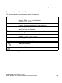
1.3 Conventions Used . . . . . . . . . . . . . . . . . . . . . . . . . . . . . . . . . . . . . . . . . . . . . . . . . . . .
1-1
1-1
1-1
1-3
2 Preparing the Board . . . . . . . . . . . . . . . . . . . . . . . . . . . . . . . . . . . . . . . . . . . . . . . . . . .
2.1 Starting the HG 1500 . . . . . . . . . . . . . . . . . . . . . . . . . . . . . . . . . . . . . . . . . . . . . . . . . .
2.1.1 Firmware Start Routine . . . . . . . . . . . . . . . . . . . . . . . . . . . . . . . . . . . . . . . . . . . . .
2.1.2 LED Startup Display . . . . . . . . . . . . . . . . . . . . . . . . . . . . . . . . . . . . . . . . . . . . . . .
2.1.3 Interrupting the Boot Procedure . . . . . . . . . . . . . . . . . . . . . . . . . . . . . . . . . . . . . .
2.2 Configuring the HiPath HG 1500 . . . . . . . . . . . . . . . . . . . . . . . . . . . . . . . . . . . . . . . . .
2.2.1 Configuration via CLI Interface . . . . . . . . . . . . . . . . . . . . . . . . . . . . . . . . . . . . . . .
2.2.2 Configuration via HiPath 3000 Manager E . . . . . . . . . . . . . . . . . . . . . . . . . . . . . .
2-1
2-1
2-1
2-2
2-2
2-2
2-3
2-4
3 WBM . . . . . . . . . . . . . . . . . . . . . . . . . . . . . . . . . . . . . . . . . . . . . . . . . . . . . . . . . . . . . . . . 3-1
3.1 Starting WBM. . . . . . . . . . . . . . . . . . . . . . . . . . . . . . . . . . . . . . . . . . . . . . . . . . . . . . . . 3-2
3.2 WBM Application Interface . . . . . . . . . . . . . . . . . . . . . . . . . . . . . . . . . . . . . . . . . . . . . 3-4
3.2.1 Modules. . . . . . . . . . . . . . . . . . . . . . . . . . . . . . . . . . . . . . . . . . . . . . . . . . . . . . . . . 3-5
3.2.1.1 Front Panel . . . . . . . . . . . . . . . . . . . . . . . . . . . . . . . . . . . . . . . . . . . . . . . . . . . 3-5
3.2.1.2 Wizards. . . . . . . . . . . . . . . . . . . . . . . . . . . . . . . . . . . . . . . . . . . . . . . . . . . . . . 3-6
3.2.1.3 Explorers . . . . . . . . . . . . . . . . . . . . . . . . . . . . . . . . . . . . . . . . . . . . . . . . . . . . 3-6
3.2.1.4 Maintenance . . . . . . . . . . . . . . . . . . . . . . . . . . . . . . . . . . . . . . . . . . . . . . . . . . 3-7
3.2.1.5 Help . . . . . . . . . . . . . . . . . . . . . . . . . . . . . . . . . . . . . . . . . . . . . . . . . . . . . . . . 3-7
3.2.1.6 Logoff . . . . . . . . . . . . . . . . . . . . . . . . . . . . . . . . . . . . . . . . . . . . . . . . . . . . . . . 3-8
3.2.2 Icons in the WBM Window’s Control Area. . . . . . . . . . . . . . . . . . . . . . . . . . . . . . . 3-8
3.2.3 Icons in the WBM Tree Representations. . . . . . . . . . . . . . . . . . . . . . . . . . . . . . . 3-11
3.2.4 Dialogs and Dialog Elements . . . . . . . . . . . . . . . . . . . . . . . . . . . . . . . . . . . . . . . 3-13
3.2.5 Table Editor . . . . . . . . . . . . . . . . . . . . . . . . . . . . . . . . . . . . . . . . . . . . . . . . . . . . . 3-14
3.2.5.1 Table Display . . . . . . . . . . . . . . . . . . . . . . . . . . . . . . . . . . . . . . . . . . . . . . . . 3-15
3.2.5.2 Processing Table Cells . . . . . . . . . . . . . . . . . . . . . . . . . . . . . . . . . . . . . . . . . 3-15
3.3 Alternative Management over CLI (Console). . . . . . . . . . . . . . . . . . . . . . . . . . . . . . . 3-16
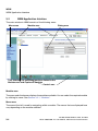
3.4 SNMP Management . . . . . . . . . . . . . . . . . . . . . . . . . . . . . . . . . . . . . . . . . . . . . . . . . 3-16
3.5 HiPath Management with HiPath 3000 Manager E . . . . . . . . . . . . . . . . . . . . . . . . . . 3-17
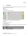
4 Front panel . . . . . . . . . . . . . . . . . . . . . . . . . . . . . . . . . . . . . . . . . . . . . . . . . . . . . . . . . . 4-1
5 Wizard . . . . . . . . . . . . . . . . . . . . . . . . . . . . . . . . . . . . . . . . . . . . . . . . . . . . . . . . . . . . . .
5.1 Initial Setup . . . . . . . . . . . . . . . . . . . . . . . . . . . . . . . . . . . . . . . . . . . . . . . . . . . . . . . . .
5.1.1 Gateway Properties. . . . . . . . . . . . . . . . . . . . . . . . . . . . . . . . . . . . . . . . . . . . . . . .
5.1.2 LAN2 . . . . . . . . . . . . . . . . . . . . . . . . . . . . . . . . . . . . . . . . . . . . . . . . . . . . . . . . . . .
5.1.2.1 Dialog for the operating mode: LAN2 . . . . . . . . . . . . . . . . . . . . . . . . . . . . . . .
5.1.2.2 Dialog for the operating mode: DSL Connection Type PPTP. . . . . . . . . . . . .
5.1.2.3 Dialog for the operating mode: DSL Connection Type PPPoE. . . . . . . . . . . .
5-1
5-1
5-1
5-2
5-3
5-4
5-7
A31003-H3580-M103-2-76A9, 01-2009
HiPath 3000/5000 V8 - HG 1500 V8, Administrator Documentation
0-1
bktoc.fm
Contents
Nur für den internen Gebrauch
5.1.3 Codec Parameters . . . . . . . . . . . . . . . . . . . . . . . . . . . . . . . . . . . . . . . . . . . . . . . . . 5-8
6 Maintenance . . . . . . . . . . . . . . . . . . . . . . . . . . . . . . . . . . . . . . . . . . . . . . . . . . . . . . . . . . 6-1
6.1 Configuration. . . . . . . . . . . . . . . . . . . . . . . . . . . . . . . . . . . . . . . . . . . . . . . . . . . . . . . . . 6-1
6.1.1 Configuration Data . . . . . . . . . . . . . . . . . . . . . . . . . . . . . . . . . . . . . . . . . . . . . . . . . 6-1
6.1.1.1 Load from Gateway . . . . . . . . . . . . . . . . . . . . . . . . . . . . . . . . . . . . . . . . . . . . . 6-2
6.1.1.2 Load to Gateway . . . . . . . . . . . . . . . . . . . . . . . . . . . . . . . . . . . . . . . . . . . . . . . 6-3
6.1.1.3 Reset Configuration to Factory Default . . . . . . . . . . . . . . . . . . . . . . . . . . . . . . 6-5
6.1.2 VPN/SSL Data . . . . . . . . . . . . . . . . . . . . . . . . . . . . . . . . . . . . . . . . . . . . . . . . . . . . 6-5
6.1.2.1 Load from Gateway . . . . . . . . . . . . . . . . . . . . . . . . . . . . . . . . . . . . . . . . . . . . . 6-5
6.1.2.2 Load to Gateway . . . . . . . . . . . . . . . . . . . . . . . . . . . . . . . . . . . . . . . . . . . . . . . 6-6
6.2 Software Image . . . . . . . . . . . . . . . . . . . . . . . . . . . . . . . . . . . . . . . . . . . . . . . . . . . . . . . 6-7
6.2.1 Software Image . . . . . . . . . . . . . . . . . . . . . . . . . . . . . . . . . . . . . . . . . . . . . . . . . . . 6-7
6.2.1.1 Load to Gateway . . . . . . . . . . . . . . . . . . . . . . . . . . . . . . . . . . . . . . . . . . . . . . . 6-7
6.3 Firmware . . . . . . . . . . . . . . . . . . . . . . . . . . . . . . . . . . . . . . . . . . . . . . . . . . . . . . . . . . . . 6-9
6.3.1 Firmware. . . . . . . . . . . . . . . . . . . . . . . . . . . . . . . . . . . . . . . . . . . . . . . . . . . . . . . . . 6-9
6.3.1.1 Load to Gateway . . . . . . . . . . . . . . . . . . . . . . . . . . . . . . . . . . . . . . . . . . . . . . . 6-9
6.4 Multigateway Administration . . . . . . . . . . . . . . . . . . . . . . . . . . . . . . . . . . . . . . . . . . . . 6-11
6.4.1 List of Gateways . . . . . . . . . . . . . . . . . . . . . . . . . . . . . . . . . . . . . . . . . . . . . . . . . . 6-11
6.4.1.1 Display All Gateways . . . . . . . . . . . . . . . . . . . . . . . . . . . . . . . . . . . . . . . . . . . 6-12
6.4.1.2 Display Selected Gateways . . . . . . . . . . . . . . . . . . . . . . . . . . . . . . . . . . . . . . 6-12
6.4.1.3 Display Unselected Gateways . . . . . . . . . . . . . . . . . . . . . . . . . . . . . . . . . . . . 6-13
6.4.1.4 Select All Gateways for Distribution. . . . . . . . . . . . . . . . . . . . . . . . . . . . . . . . 6-13
6.4.1.5 Deselect All Gateways for Distribution. . . . . . . . . . . . . . . . . . . . . . . . . . . . . . 6-13
6.4.1.6 Display All Gateways with Status Information . . . . . . . . . . . . . . . . . . . . . . . . 6-13
6.4.1.7 Add Gateway . . . . . . . . . . . . . . . . . . . . . . . . . . . . . . . . . . . . . . . . . . . . . . . . . 6-14
6.4.1.8 Delete All Gateways. . . . . . . . . . . . . . . . . . . . . . . . . . . . . . . . . . . . . . . . . . . . 6-15
6.4.1.9 Deselect Gateway for Distribution . . . . . . . . . . . . . . . . . . . . . . . . . . . . . . . . . 6-15
6.4.1.10 Select Gateway for Distribution . . . . . . . . . . . . . . . . . . . . . . . . . . . . . . . . . . 6-15
6.4.1.11 Display Gateway Properties. . . . . . . . . . . . . . . . . . . . . . . . . . . . . . . . . . . . . 6-15
6.4.1.12 Display Gateway Status Information . . . . . . . . . . . . . . . . . . . . . . . . . . . . . . 6-16
6.4.1.13 Edit Gateway Properties . . . . . . . . . . . . . . . . . . . . . . . . . . . . . . . . . . . . . . . 6-16
6.4.1.14 Delete Gateway . . . . . . . . . . . . . . . . . . . . . . . . . . . . . . . . . . . . . . . . . . . . . . 6-16
6.4.2 List of Configuration Tables . . . . . . . . . . . . . . . . . . . . . . . . . . . . . . . . . . . . . . . . . 6-17
6.4.2.1 Display List of Configuration Tables . . . . . . . . . . . . . . . . . . . . . . . . . . . . . . . 6-17
6.4.2.2 Edit List of Configuration Tables . . . . . . . . . . . . . . . . . . . . . . . . . . . . . . . . . . 6-17
6.4.3 Distribution . . . . . . . . . . . . . . . . . . . . . . . . . . . . . . . . . . . . . . . . . . . . . . . . . . . . . . 6-18
6.4.3.1 Distribute Configuration . . . . . . . . . . . . . . . . . . . . . . . . . . . . . . . . . . . . . . . . . 6-18
6.4.4 Job List . . . . . . . . . . . . . . . . . . . . . . . . . . . . . . . . . . . . . . . . . . . . . . . . . . . . . . . . . 6-19
6.4.4.1 Display List of Jobs . . . . . . . . . . . . . . . . . . . . . . . . . . . . . . . . . . . . . . . . . . . . 6-19
6.5 Job List . . . . . . . . . . . . . . . . . . . . . . . . . . . . . . . . . . . . . . . . . . . . . . . . . . . . . . . . . . . . 6-20
6.6 Traces . . . . . . . . . . . . . . . . . . . . . . . . . . . . . . . . . . . . . . . . . . . . . . . . . . . . . . . . . . . . . 6-21
6.6.1 Trace Format Configuration . . . . . . . . . . . . . . . . . . . . . . . . . . . . . . . . . . . . . . . . . 6-22
6.6.1.1 Display Trace Configuration. . . . . . . . . . . . . . . . . . . . . . . . . . . . . . . . . . . . . . 6-22
6.6.1.2 Edit Trace Configuration . . . . . . . . . . . . . . . . . . . . . . . . . . . . . . . . . . . . . . . . 6-22
6.6.2 Trace Output Interfaces . . . . . . . . . . . . . . . . . . . . . . . . . . . . . . . . . . . . . . . . . . . . 6-24
0-2
A31003-H3580-M103-2-76A9, 01-2009
HiPath 3000/5000 V8 - HG 1500 V8, Administrator Documentation
bktoc.fm
Nur für den internen Gebrauch
Contents
6.6.2.1 Display Trace Output Interfaces . . . . . . . . . . . . . . . . . . . . . . . . . . . . . . . . . .
6.6.2.2 Edit Trace Output Interfaces. . . . . . . . . . . . . . . . . . . . . . . . . . . . . . . . . . . . .
6.6.2.3 Board Overload Caused by Trace Information . . . . . . . . . . . . . . . . . . . . . . .
6.6.3 Trace Log . . . . . . . . . . . . . . . . . . . . . . . . . . . . . . . . . . . . . . . . . . . . . . . . . . . . . .
6.6.3.1 Load via TFTP . . . . . . . . . . . . . . . . . . . . . . . . . . . . . . . . . . . . . . . . . . . . . . .
6.6.3.2 Load via HTTP . . . . . . . . . . . . . . . . . . . . . . . . . . . . . . . . . . . . . . . . . . . . . . .
6.6.3.3 Expert Mode . . . . . . . . . . . . . . . . . . . . . . . . . . . . . . . . . . . . . . . . . . . . . . . . .
6.6.3.4 Clear Trace Log . . . . . . . . . . . . . . . . . . . . . . . . . . . . . . . . . . . . . . . . . . . . . .
6.6.4 Customer Trace Log . . . . . . . . . . . . . . . . . . . . . . . . . . . . . . . . . . . . . . . . . . . . . .
6.6.4.1 Display . . . . . . . . . . . . . . . . . . . . . . . . . . . . . . . . . . . . . . . . . . . . . . . . . . . . .
6.6.4.2 Load via HTTP . . . . . . . . . . . . . . . . . . . . . . . . . . . . . . . . . . . . . . . . . . . . . . .
6.6.4.3 Clear Trace Log . . . . . . . . . . . . . . . . . . . . . . . . . . . . . . . . . . . . . . . . . . . . . .
6.6.5 Trace Encryption . . . . . . . . . . . . . . . . . . . . . . . . . . . . . . . . . . . . . . . . . . . . . . . . .
6.6.5.1 Import X.509 File for Secure Trace. . . . . . . . . . . . . . . . . . . . . . . . . . . . . . . .
6.6.5.2 Secure Trace Settings . . . . . . . . . . . . . . . . . . . . . . . . . . . . . . . . . . . . . . . . .
6.6.5.3 Edit Secure Trace Passphrase . . . . . . . . . . . . . . . . . . . . . . . . . . . . . . . . . . .
6.6.6 Trace Profiles . . . . . . . . . . . . . . . . . . . . . . . . . . . . . . . . . . . . . . . . . . . . . . . . . . .
6.6.6.1 Display All Trace Profiles . . . . . . . . . . . . . . . . . . . . . . . . . . . . . . . . . . . . . . .
6.6.6.2 Add Trace Profile (Empty Profile) . . . . . . . . . . . . . . . . . . . . . . . . . . . . . . . . .
6.6.6.3 Add Trace Profile (with Current Trace Settings) . . . . . . . . . . . . . . . . . . . . . .
6.6.6.4 Stop All Trace Profiles . . . . . . . . . . . . . . . . . . . . . . . . . . . . . . . . . . . . . . . . .
6.6.6.5 Display Trace Profile. . . . . . . . . . . . . . . . . . . . . . . . . . . . . . . . . . . . . . . . . . .
6.6.6.6 Start Trace Profile. . . . . . . . . . . . . . . . . . . . . . . . . . . . . . . . . . . . . . . . . . . . .
6.6.6.7 Stop Trace Profile . . . . . . . . . . . . . . . . . . . . . . . . . . . . . . . . . . . . . . . . . . . . .
6.6.6.8 Edit Trace Profile . . . . . . . . . . . . . . . . . . . . . . . . . . . . . . . . . . . . . . . . . . . . .
6.6.6.9 Delete Trace Profile . . . . . . . . . . . . . . . . . . . . . . . . . . . . . . . . . . . . . . . . . . .
6.6.7 Trace Components . . . . . . . . . . . . . . . . . . . . . . . . . . . . . . . . . . . . . . . . . . . . . . .
6.6.7.1 Display All Trace Components . . . . . . . . . . . . . . . . . . . . . . . . . . . . . . . . . . .
6.6.7.2 Display Started Trace Components . . . . . . . . . . . . . . . . . . . . . . . . . . . . . . .
6.6.7.3 Display Stopped Trace Components . . . . . . . . . . . . . . . . . . . . . . . . . . . . . .
6.6.7.4 Edit Trace Components . . . . . . . . . . . . . . . . . . . . . . . . . . . . . . . . . . . . . . . .
6.6.7.5 Stop All Trace Components . . . . . . . . . . . . . . . . . . . . . . . . . . . . . . . . . . . . .
6.6.7.6 Display Trace Component . . . . . . . . . . . . . . . . . . . . . . . . . . . . . . . . . . . . . .
6.6.7.7 Edit Trace Component . . . . . . . . . . . . . . . . . . . . . . . . . . . . . . . . . . . . . . . . .
6.6.7.8 Start Trace Component . . . . . . . . . . . . . . . . . . . . . . . . . . . . . . . . . . . . . . . .
6.6.7.9 Stop Trace Component . . . . . . . . . . . . . . . . . . . . . . . . . . . . . . . . . . . . . . . .
6.7 Events . . . . . . . . . . . . . . . . . . . . . . . . . . . . . . . . . . . . . . . . . . . . . . . . . . . . . . . . . . . .
6.7.1 Event Configuration. . . . . . . . . . . . . . . . . . . . . . . . . . . . . . . . . . . . . . . . . . . . . . .
6.7.1.1 Display Event Configuration . . . . . . . . . . . . . . . . . . . . . . . . . . . . . . . . . . . . .
6.7.1.2 Edit Event Configuration . . . . . . . . . . . . . . . . . . . . . . . . . . . . . . . . . . . . . . . .
6.7.2 Event Log . . . . . . . . . . . . . . . . . . . . . . . . . . . . . . . . . . . . . . . . . . . . . . . . . . . . . .
6.7.2.1 Load via TFTP . . . . . . . . . . . . . . . . . . . . . . . . . . . . . . . . . . . . . . . . . . . . . . .
6.7.2.2 Load via HTTP . . . . . . . . . . . . . . . . . . . . . . . . . . . . . . . . . . . . . . . . . . . . . . .
6.7.2.3 Clear Event Log . . . . . . . . . . . . . . . . . . . . . . . . . . . . . . . . . . . . . . . . . . . . . .
A31003-H3580-M103-2-76A9, 01-2009
HiPath 3000/5000 V8 - HG 1500 V8, Administrator Documentation
6-24
6-24
6-25
6-26
6-26
6-27
6-27
6-27
6-28
6-28
6-30
6-30
6-31
6-33
6-33
6-36
6-37
6-37
6-38
6-38
6-39
6-39
6-40
6-40
6-40
6-40
6-41
6-41
6-42
6-42
6-42
6-43
6-43
6-43
6-44
6-44
6-45
6-45
6-45
6-46
6-46
6-46
6-47
6-47
0-3
bktoc.fm
Contents
Nur für den internen Gebrauch
6.7.3 E-mail . . . . . . . . . . . . . . . . . . . . . . . . . . . . . . . . . . . . . . . . . . . . . . . . . . . . . . . . . .
6.7.3.1 Display E-mail Settings . . . . . . . . . . . . . . . . . . . . . . . . . . . . . . . . . . . . . . . . .
6.7.3.2 Edit E-mail Settings . . . . . . . . . . . . . . . . . . . . . . . . . . . . . . . . . . . . . . . . . . . .
6.7.4 Reaction Table . . . . . . . . . . . . . . . . . . . . . . . . . . . . . . . . . . . . . . . . . . . . . . . . . . .
6.7.4.1 Display All Events . . . . . . . . . . . . . . . . . . . . . . . . . . . . . . . . . . . . . . . . . . . . .
6.7.4.2 Display Event . . . . . . . . . . . . . . . . . . . . . . . . . . . . . . . . . . . . . . . . . . . . . . . . .
6.7.4.3 Edit Event. . . . . . . . . . . . . . . . . . . . . . . . . . . . . . . . . . . . . . . . . . . . . . . . . . . .
6.7.5 Diagnosis Logs . . . . . . . . . . . . . . . . . . . . . . . . . . . . . . . . . . . . . . . . . . . . . . . . . . .
6.7.5.1 Get Diagnosis Logs . . . . . . . . . . . . . . . . . . . . . . . . . . . . . . . . . . . . . . . . . . . .
6.8 SNMP . . . . . . . . . . . . . . . . . . . . . . . . . . . . . . . . . . . . . . . . . . . . . . . . . . . . . . . . . . . . .
6.8.1 Communities. . . . . . . . . . . . . . . . . . . . . . . . . . . . . . . . . . . . . . . . . . . . . . . . . . . . .
6.8.1.1 Display Communities . . . . . . . . . . . . . . . . . . . . . . . . . . . . . . . . . . . . . . . . . . .
6.8.1.2 Read Communities . . . . . . . . . . . . . . . . . . . . . . . . . . . . . . . . . . . . . . . . . . . .
6.8.1.3 Display Read Communities . . . . . . . . . . . . . . . . . . . . . . . . . . . . . . . . . . . . . .
6.8.1.4 Add Read Community . . . . . . . . . . . . . . . . . . . . . . . . . . . . . . . . . . . . . . . . . .
6.8.1.5 Write Communities. . . . . . . . . . . . . . . . . . . . . . . . . . . . . . . . . . . . . . . . . . . . .
6.8.1.6 Display Write Communities . . . . . . . . . . . . . . . . . . . . . . . . . . . . . . . . . . . . . .
6.8.1.7 Add Write Community . . . . . . . . . . . . . . . . . . . . . . . . . . . . . . . . . . . . . . . . . .
6.8.1.8 Trap Communities . . . . . . . . . . . . . . . . . . . . . . . . . . . . . . . . . . . . . . . . . . . . .
6.8.1.9 Display Trap Communities. . . . . . . . . . . . . . . . . . . . . . . . . . . . . . . . . . . . . . .
6.8.1.10 Add Trap Community . . . . . . . . . . . . . . . . . . . . . . . . . . . . . . . . . . . . . . . . . .
6.8.1.11 Display Community . . . . . . . . . . . . . . . . . . . . . . . . . . . . . . . . . . . . . . . . . . .
6.8.1.12 Edit Community . . . . . . . . . . . . . . . . . . . . . . . . . . . . . . . . . . . . . . . . . . . . . .
6.8.1.13 Delete Community . . . . . . . . . . . . . . . . . . . . . . . . . . . . . . . . . . . . . . . . . . . .
6.8.2 Traps . . . . . . . . . . . . . . . . . . . . . . . . . . . . . . . . . . . . . . . . . . . . . . . . . . . . . . . . . .
6.8.2.1 Display All Traps . . . . . . . . . . . . . . . . . . . . . . . . . . . . . . . . . . . . . . . . . . . . . .
6.8.2.2 Display All Critical Traps . . . . . . . . . . . . . . . . . . . . . . . . . . . . . . . . . . . . . . . .
6.8.2.3 Refresh . . . . . . . . . . . . . . . . . . . . . . . . . . . . . . . . . . . . . . . . . . . . . . . . . . . . .
6.8.2.4 Display Trap. . . . . . . . . . . . . . . . . . . . . . . . . . . . . . . . . . . . . . . . . . . . . . . . . .
6.9 Admin Log . . . . . . . . . . . . . . . . . . . . . . . . . . . . . . . . . . . . . . . . . . . . . . . . . . . . . . . . . .
6.9.1 Configuration . . . . . . . . . . . . . . . . . . . . . . . . . . . . . . . . . . . . . . . . . . . . . . . . . . . .
6.9.1.1 Display Configuration. . . . . . . . . . . . . . . . . . . . . . . . . . . . . . . . . . . . . . . . . . .
6.9.1.2 Edit Configuration . . . . . . . . . . . . . . . . . . . . . . . . . . . . . . . . . . . . . . . . . . . . .
6.9.2 Admin Log Data . . . . . . . . . . . . . . . . . . . . . . . . . . . . . . . . . . . . . . . . . . . . . . . . . .
6.9.2.1 Load via TFTP . . . . . . . . . . . . . . . . . . . . . . . . . . . . . . . . . . . . . . . . . . . . . . . .
6.9.2.2 Load via HTTP . . . . . . . . . . . . . . . . . . . . . . . . . . . . . . . . . . . . . . . . . . . . . . . .
6.9.2.3 Delete Log File on Gateway. . . . . . . . . . . . . . . . . . . . . . . . . . . . . . . . . . . . . .
6.10 Actions . . . . . . . . . . . . . . . . . . . . . . . . . . . . . . . . . . . . . . . . . . . . . . . . . . . . . . . . . . .
6.10.1 Manual Actions . . . . . . . . . . . . . . . . . . . . . . . . . . . . . . . . . . . . . . . . . . . . . . . . . .
6.10.1.1 Trace Log. . . . . . . . . . . . . . . . . . . . . . . . . . . . . . . . . . . . . . . . . . . . . . . . . . .
6.10.1.2 Event Log. . . . . . . . . . . . . . . . . . . . . . . . . . . . . . . . . . . . . . . . . . . . . . . . . . .
6.10.1.3 Admin Log . . . . . . . . . . . . . . . . . . . . . . . . . . . . . . . . . . . . . . . . . . . . . . . . . .
6.10.1.4 PPP Log. . . . . . . . . . . . . . . . . . . . . . . . . . . . . . . . . . . . . . . . . . . . . . . . . . . .
6.10.1.5 All Logs . . . . . . . . . . . . . . . . . . . . . . . . . . . . . . . . . . . . . . . . . . . . . . . . . . . .
0-4
6-48
6-48
6-48
6-49
6-49
6-50
6-50
6-51
6-51
6-51
6-52
6-52
6-52
6-53
6-53
6-54
6-54
6-54
6-55
6-55
6-56
6-56
6-56
6-57
6-57
6-58
6-58
6-59
6-59
6-60
6-60
6-60
6-60
6-61
6-61
6-62
6-62
6-63
6-63
6-63
6-64
6-64
6-64
6-64
A31003-H3580-M103-2-76A9, 01-2009
HiPath 3000/5000 V8 - HG 1500 V8, Administrator Documentation
bktoc.fm
Nur für den internen Gebrauch
Contents
6.10.1.6 Delete Data. . . . . . . . . . . . . . . . . . . . . . . . . . . . . . . . . . . . . . . . . . . . . . . . .
6.10.1.7 Load data via HTTP . . . . . . . . . . . . . . . . . . . . . . . . . . . . . . . . . . . . . . . . . .
6.10.2 Automatic Actions . . . . . . . . . . . . . . . . . . . . . . . . . . . . . . . . . . . . . . . . . . . . . . .
6.10.2.1 Garbage Collection . . . . . . . . . . . . . . . . . . . . . . . . . . . . . . . . . . . . . . . . . . .
6.10.2.2 Software Activation . . . . . . . . . . . . . . . . . . . . . . . . . . . . . . . . . . . . . . . . . . .
6.10.2.3 DLS Notification . . . . . . . . . . . . . . . . . . . . . . . . . . . . . . . . . . . . . . . . . . . . .
6-65
6-65
6-66
6-66
6-67
6-70
7 Explorers . . . . . . . . . . . . . . . . . . . . . . . . . . . . . . . . . . . . . . . . . . . . . . . . . . . . . . . . . . . . 7-1
7.1 Basic Settings . . . . . . . . . . . . . . . . . . . . . . . . . . . . . . . . . . . . . . . . . . . . . . . . . . . . . . . 7-1
7.1.1 System . . . . . . . . . . . . . . . . . . . . . . . . . . . . . . . . . . . . . . . . . . . . . . . . . . . . . . . . . 7-2
7.1.1.1 Hardware Configuration . . . . . . . . . . . . . . . . . . . . . . . . . . . . . . . . . . . . . . . . . 7-2
7.1.1.2 Software Build . . . . . . . . . . . . . . . . . . . . . . . . . . . . . . . . . . . . . . . . . . . . . . . . 7-3
7.1.1.3 CPU . . . . . . . . . . . . . . . . . . . . . . . . . . . . . . . . . . . . . . . . . . . . . . . . . . . . . . . . 7-3
7.1.1.4 Temperature Sensor. . . . . . . . . . . . . . . . . . . . . . . . . . . . . . . . . . . . . . . . . . . . 7-3
7.1.1.5 Memory. . . . . . . . . . . . . . . . . . . . . . . . . . . . . . . . . . . . . . . . . . . . . . . . . . . . . . 7-4
7.1.1.6 Flash . . . . . . . . . . . . . . . . . . . . . . . . . . . . . . . . . . . . . . . . . . . . . . . . . . . . . . . . 7-6
7.1.1.7 Net Stack Resources . . . . . . . . . . . . . . . . . . . . . . . . . . . . . . . . . . . . . . . . . . . 7-7
7.1.2 Gateway . . . . . . . . . . . . . . . . . . . . . . . . . . . . . . . . . . . . . . . . . . . . . . . . . . . . . . . . 7-8
7.1.2.1 Display Gateway Properties . . . . . . . . . . . . . . . . . . . . . . . . . . . . . . . . . . . . . . 7-8
7.1.2.2 Edit Gateway Properties . . . . . . . . . . . . . . . . . . . . . . . . . . . . . . . . . . . . . . . . . 7-8
7.1.3 License Management . . . . . . . . . . . . . . . . . . . . . . . . . . . . . . . . . . . . . . . . . . . . . 7-10
7.1.3.1 Display Licenses. . . . . . . . . . . . . . . . . . . . . . . . . . . . . . . . . . . . . . . . . . . . . . 7-10
7.1.4 ILS Settings . . . . . . . . . . . . . . . . . . . . . . . . . . . . . . . . . . . . . . . . . . . . . . . . . . . . . 7-10
7.1.4.1 Display . . . . . . . . . . . . . . . . . . . . . . . . . . . . . . . . . . . . . . . . . . . . . . . . . . . . . 7-11
7.1.4.2 Edit . . . . . . . . . . . . . . . . . . . . . . . . . . . . . . . . . . . . . . . . . . . . . . . . . . . . . . . . 7-11
7.1.5 DynDNS . . . . . . . . . . . . . . . . . . . . . . . . . . . . . . . . . . . . . . . . . . . . . . . . . . . . . . . 7-11
7.1.5.1 DynDNS Service. . . . . . . . . . . . . . . . . . . . . . . . . . . . . . . . . . . . . . . . . . . . . . 7-12
7.1.5.2 Update Timer for DNS Names . . . . . . . . . . . . . . . . . . . . . . . . . . . . . . . . . . . 7-13
7.1.6 AF/EF Codepoints . . . . . . . . . . . . . . . . . . . . . . . . . . . . . . . . . . . . . . . . . . . . . . . . 7-15
7.1.6.1 Display AF/EF Codepoints . . . . . . . . . . . . . . . . . . . . . . . . . . . . . . . . . . . . . . 7-15
7.1.7 Quality of Service . . . . . . . . . . . . . . . . . . . . . . . . . . . . . . . . . . . . . . . . . . . . . . . . 7-16
7.1.7.1 Display Quality of Service Settings. . . . . . . . . . . . . . . . . . . . . . . . . . . . . . . . 7-16
7.1.7.2 Editing Quality of Service settings . . . . . . . . . . . . . . . . . . . . . . . . . . . . . . . . 7-16
7.1.8 SNTP settings . . . . . . . . . . . . . . . . . . . . . . . . . . . . . . . . . . . . . . . . . . . . . . . . . . . 7-17
7.1.8.1 Display . . . . . . . . . . . . . . . . . . . . . . . . . . . . . . . . . . . . . . . . . . . . . . . . . . . . . 7-18
7.1.8.2 Edit . . . . . . . . . . . . . . . . . . . . . . . . . . . . . . . . . . . . . . . . . . . . . . . . . . . . . . . . 7-18
7.1.8.3 Reset Time Request Counter . . . . . . . . . . . . . . . . . . . . . . . . . . . . . . . . . . . . 7-18
7.1.9 Port management . . . . . . . . . . . . . . . . . . . . . . . . . . . . . . . . . . . . . . . . . . . . . . . . 7-20
7.1.9.1 Display All Used Ports . . . . . . . . . . . . . . . . . . . . . . . . . . . . . . . . . . . . . . . . . 7-20
7.1.9.2 Displaying all downloaded ports . . . . . . . . . . . . . . . . . . . . . . . . . . . . . . . . . . 7-21
7.1.9.3 Displaying all local ports . . . . . . . . . . . . . . . . . . . . . . . . . . . . . . . . . . . . . . . . 7-21
7.1.9.4 Displaying Global Port Manager settings . . . . . . . . . . . . . . . . . . . . . . . . . . . 7-21
7.1.9.5 Editing Global Port Manager settings . . . . . . . . . . . . . . . . . . . . . . . . . . . . . . 7-22
7.1.9.6 Locally Administered Ports . . . . . . . . . . . . . . . . . . . . . . . . . . . . . . . . . . . . . 7-22
7.1.9.7 Displaying all local ports . . . . . . . . . . . . . . . . . . . . . . . . . . . . . . . . . . . . . . . . 7-23
A31003-H3580-M103-2-76A9, 01-2009
HiPath 3000/5000 V8 - HG 1500 V8, Administrator Documentation
0-5
bktoc.fm
Contents
Nur für den internen Gebrauch
7.1.9.8 Adding a locally administered port . . . . . . . . . . . . . . . . . . . . . . . . . . . . . . . . .
7.1.9.9 Display Port . . . . . . . . . . . . . . . . . . . . . . . . . . . . . . . . . . . . . . . . . . . . . . . . . .
7.1.9.10 Edit Port . . . . . . . . . . . . . . . . . . . . . . . . . . . . . . . . . . . . . . . . . . . . . . . . . . . .
7.1.9.11 Delete Port . . . . . . . . . . . . . . . . . . . . . . . . . . . . . . . . . . . . . . . . . . . . . . . . . .
7.1.10 Online Help Directory . . . . . . . . . . . . . . . . . . . . . . . . . . . . . . . . . . . . . . . . . . . . .
7.1.10.1 Display Online Help Directory . . . . . . . . . . . . . . . . . . . . . . . . . . . . . . . . . . .
7.1.10.2 Edit Online Help Directory . . . . . . . . . . . . . . . . . . . . . . . . . . . . . . . . . . . . . .
7.2 Security . . . . . . . . . . . . . . . . . . . . . . . . . . . . . . . . . . . . . . . . . . . . . . . . . . . . . . . . . . . .
7.2.1 MAC Address Filtering . . . . . . . . . . . . . . . . . . . . . . . . . . . . . . . . . . . . . . . . . . . . .
7.2.1.1 Display MAC Address Filtering . . . . . . . . . . . . . . . . . . . . . . . . . . . . . . . . . . .
7.2.1.2 Enable MAC Address Filtering. . . . . . . . . . . . . . . . . . . . . . . . . . . . . . . . . . . .
7.2.1.3 Disable MAC Address Filtering . . . . . . . . . . . . . . . . . . . . . . . . . . . . . . . . . . .
7.2.1.4 Add Rule for MAC Address Filtering . . . . . . . . . . . . . . . . . . . . . . . . . . . . . . .
7.2.1.5 Delete all MAC Address Filtering Rules. . . . . . . . . . . . . . . . . . . . . . . . . . . . .
7.2.1.6 MAC Address Filtering Table Editor. . . . . . . . . . . . . . . . . . . . . . . . . . . . . . . .
7.2.1.7 Display Rule for MAC Address Filtering. . . . . . . . . . . . . . . . . . . . . . . . . . . . .
7.2.1.8 Edit Rule for MAC Address Filtering . . . . . . . . . . . . . . . . . . . . . . . . . . . . . . .
7.2.1.9 Delete MAC Address Filtering Rule . . . . . . . . . . . . . . . . . . . . . . . . . . . . . . . .
7.2.1.10 Activate Rule . . . . . . . . . . . . . . . . . . . . . . . . . . . . . . . . . . . . . . . . . . . . . . . .
7.2.1.11 Deactivate Rule . . . . . . . . . . . . . . . . . . . . . . . . . . . . . . . . . . . . . . . . . . . . . .
7.2.2 IP Address Filtering . . . . . . . . . . . . . . . . . . . . . . . . . . . . . . . . . . . . . . . . . . . . . . .
7.2.2.1 Display IP Address Filtering. . . . . . . . . . . . . . . . . . . . . . . . . . . . . . . . . . . . . .
7.2.2.2 Enable IP Address Filtering . . . . . . . . . . . . . . . . . . . . . . . . . . . . . . . . . . . . . .
7.2.2.3 Disable IP Address Filtering. . . . . . . . . . . . . . . . . . . . . . . . . . . . . . . . . . . . . .
7.2.2.4 Add Rule for IP Address Filtering. . . . . . . . . . . . . . . . . . . . . . . . . . . . . . . . . .
7.2.2.5 Delete all IP Address Filtering Rules . . . . . . . . . . . . . . . . . . . . . . . . . . . . . . .
7.2.2.6 IP Address Filtering Table Editor . . . . . . . . . . . . . . . . . . . . . . . . . . . . . . . . . .
7.2.2.7 Display Rule for IP Address Filtering . . . . . . . . . . . . . . . . . . . . . . . . . . . . . . .
7.2.2.8 Edit Rule for IP Address Filtering. . . . . . . . . . . . . . . . . . . . . . . . . . . . . . . . . .
7.2.2.9 Delete IP Address Filtering Rule . . . . . . . . . . . . . . . . . . . . . . . . . . . . . . . . . .
7.2.2.10 Activate Rule . . . . . . . . . . . . . . . . . . . . . . . . . . . . . . . . . . . . . . . . . . . . . . . .
7.2.2.11 Deactivate Rule . . . . . . . . . . . . . . . . . . . . . . . . . . . . . . . . . . . . . . . . . . . . . .
7.2.3 IP Accounting . . . . . . . . . . . . . . . . . . . . . . . . . . . . . . . . . . . . . . . . . . . . . . . . . . . .
7.2.3.1 Display IP Accounting Parameters . . . . . . . . . . . . . . . . . . . . . . . . . . . . . . . .
7.2.3.2 Edit IP Accounting Parameters . . . . . . . . . . . . . . . . . . . . . . . . . . . . . . . . . . .
7.2.4 IP Administration Access . . . . . . . . . . . . . . . . . . . . . . . . . . . . . . . . . . . . . . . . . . .
7.2.4.1 Telnet . . . . . . . . . . . . . . . . . . . . . . . . . . . . . . . . . . . . . . . . . . . . . . . . . . . . . . .
7.2.4.2 Web-based management. . . . . . . . . . . . . . . . . . . . . . . . . . . . . . . . . . . . . . . .
7.2.4.3 Delete All IP Addresses for Administration . . . . . . . . . . . . . . . . . . . . . . . . . .
7.2.4.4 Display State of Access Check . . . . . . . . . . . . . . . . . . . . . . . . . . . . . . . . . . .
7.2.4.5 Enable Access Check . . . . . . . . . . . . . . . . . . . . . . . . . . . . . . . . . . . . . . . . . .
7.2.4.6 Disable Access Check . . . . . . . . . . . . . . . . . . . . . . . . . . . . . . . . . . . . . . . . . .
7.2.4.7 Add IP Address for Administration . . . . . . . . . . . . . . . . . . . . . . . . . . . . . . . . .
7.2.4.8 Display IP Address for Administration . . . . . . . . . . . . . . . . . . . . . . . . . . . . . .
0-6
7-23
7-23
7-24
7-24
7-25
7-25
7-25
7-27
7-27
7-28
7-28
7-29
7-29
7-30
7-30
7-30
7-31
7-31
7-31
7-32
7-32
7-33
7-33
7-33
7-34
7-35
7-35
7-36
7-36
7-36
7-37
7-37
7-38
7-38
7-38
7-39
7-40
7-40
7-40
7-41
7-41
7-42
7-43
7-44
A31003-H3580-M103-2-76A9, 01-2009
HiPath 3000/5000 V8 - HG 1500 V8, Administrator Documentation
bktoc.fm
Nur für den internen Gebrauch
Contents
7.2.4.9 Edit IP Address for Administration . . . . . . . . . . . . . . . . . . . . . . . . . . . . . . . .
7.2.4.10 Delete IP Address for Administration . . . . . . . . . . . . . . . . . . . . . . . . . . . . .
7.2.5 VPN . . . . . . . . . . . . . . . . . . . . . . . . . . . . . . . . . . . . . . . . . . . . . . . . . . . . . . . . . . .
7.2.5.1 Display General Information . . . . . . . . . . . . . . . . . . . . . . . . . . . . . . . . . . . . .
7.2.5.2 Activate the Configured VPN Tables . . . . . . . . . . . . . . . . . . . . . . . . . . . . . .
7.2.5.3 IPsec on/IPsec off. . . . . . . . . . . . . . . . . . . . . . . . . . . . . . . . . . . . . . . . . . . . .
7.2.5.4 Reset to insecure mode . . . . . . . . . . . . . . . . . . . . . . . . . . . . . . . . . . . . . . . .
7.2.5.5 Lightweight CA . . . . . . . . . . . . . . . . . . . . . . . . . . . . . . . . . . . . . . . . . . . . . . .
7.2.5.6 Generating CA certificates . . . . . . . . . . . . . . . . . . . . . . . . . . . . . . . . . . . . . .
7.2.5.7 View Certificate. . . . . . . . . . . . . . . . . . . . . . . . . . . . . . . . . . . . . . . . . . . . . . .
7.2.5.8 Delete Certificate . . . . . . . . . . . . . . . . . . . . . . . . . . . . . . . . . . . . . . . . . . . . .
7.2.5.9 Export Certificate [X.509] . . . . . . . . . . . . . . . . . . . . . . . . . . . . . . . . . . . . . . .
7.2.5.10 Generating CA-signed peer certificates [PKCS#12] . . . . . . . . . . . . . . . . . .
7.2.5.11 Updating CA-signed peer certificates [X.509]. . . . . . . . . . . . . . . . . . . . . . .
7.2.5.12 Generating Certificate Revocation Lists (CRLs) . . . . . . . . . . . . . . . . . . . . .
7.2.5.13 Certificate Management . . . . . . . . . . . . . . . . . . . . . . . . . . . . . . . . . . . . . . .
7.2.5.14 View Certificate From File. . . . . . . . . . . . . . . . . . . . . . . . . . . . . . . . . . . . . .
7.2.5.15 Trusted CA Certificates. . . . . . . . . . . . . . . . . . . . . . . . . . . . . . . . . . . . . . . .
7.2.5.16 Active Certificates . . . . . . . . . . . . . . . . . . . . . . . . . . . . . . . . . . . . . . . . . . . .
7.2.5.17 View Certificate. . . . . . . . . . . . . . . . . . . . . . . . . . . . . . . . . . . . . . . . . . . . . .
7.2.5.18 Display CRL . . . . . . . . . . . . . . . . . . . . . . . . . . . . . . . . . . . . . . . . . . . . . . . .
7.2.5.19 Configured Certificates . . . . . . . . . . . . . . . . . . . . . . . . . . . . . . . . . . . . . . . .
7.2.5.20 Importing trusted CA certificates [X.509] . . . . . . . . . . . . . . . . . . . . . . . . . .
7.2.5.21 View Certificate. . . . . . . . . . . . . . . . . . . . . . . . . . . . . . . . . . . . . . . . . . . . . .
7.2.5.22 Delete Certificate . . . . . . . . . . . . . . . . . . . . . . . . . . . . . . . . . . . . . . . . . . . .
7.2.5.23 Displaying the CRL . . . . . . . . . . . . . . . . . . . . . . . . . . . . . . . . . . . . . . . . . . .
7.2.5.24 Importing a CRL . . . . . . . . . . . . . . . . . . . . . . . . . . . . . . . . . . . . . . . . . . . . .
7.2.5.25 Peer Certificates . . . . . . . . . . . . . . . . . . . . . . . . . . . . . . . . . . . . . . . . . . . . .
7.2.5.26 Generating a Certificate Signing Request (CSR) . . . . . . . . . . . . . . . . . . . .
7.2.5.27 Importing peer certificates [PKCS#12] . . . . . . . . . . . . . . . . . . . . . . . . . . . .
7.2.5.28 View Certificate. . . . . . . . . . . . . . . . . . . . . . . . . . . . . . . . . . . . . . . . . . . . . .
7.2.5.29 Delete Certificate . . . . . . . . . . . . . . . . . . . . . . . . . . . . . . . . . . . . . . . . . . . .
7.2.5.30 Export Certificate [X.509] . . . . . . . . . . . . . . . . . . . . . . . . . . . . . . . . . . . . . .
7.2.5.31 Import Updated Certificate [X.509] . . . . . . . . . . . . . . . . . . . . . . . . . . . . . . .
7.2.5.32 Display Certificate Signing Request (CSR) . . . . . . . . . . . . . . . . . . . . . . . .
7.2.5.33 Deleting a Certificate Signing Request (CSR) . . . . . . . . . . . . . . . . . . . . . .
7.2.5.34 Exporting a Certificate Signing Requests (CSR) . . . . . . . . . . . . . . . . . . . .
7.2.5.35 Import Certificate for CSR [X.509] . . . . . . . . . . . . . . . . . . . . . . . . . . . . . . .
7.2.5.36 Services . . . . . . . . . . . . . . . . . . . . . . . . . . . . . . . . . . . . . . . . . . . . . . . . . . .
7.2.5.37 Active Services . . . . . . . . . . . . . . . . . . . . . . . . . . . . . . . . . . . . . . . . . . . . . .
7.2.5.38 Display IPsec Services . . . . . . . . . . . . . . . . . . . . . . . . . . . . . . . . . . . . . . . .
7.2.5.39 Display IPsec Service . . . . . . . . . . . . . . . . . . . . . . . . . . . . . . . . . . . . . . . . .
7.2.5.40 Configured Services . . . . . . . . . . . . . . . . . . . . . . . . . . . . . . . . . . . . . . . . . .
7.2.5.41 Display IPsec Services . . . . . . . . . . . . . . . . . . . . . . . . . . . . . . . . . . . . . . . .
A31003-H3580-M103-2-76A9, 01-2009
HiPath 3000/5000 V8 - HG 1500 V8, Administrator Documentation
7-44
7-45
7-46
7-47
7-47
7-48
7-48
7-49
7-49
7-50
7-51
7-51
7-51
7-52
7-53
7-54
7-54
7-55
7-55
7-56
7-56
7-56
7-57
7-58
7-58
7-58
7-59
7-59
7-60
7-61
7-61
7-62
7-62
7-62
7-63
7-63
7-64
7-64
7-65
7-65
7-66
7-66
7-66
7-67
0-7
bktoc.fm
Contents
Nur für den internen Gebrauch
7.2.5.42 Adding IPsec service . . . . . . . . . . . . . . . . . . . . . . . . . . . . . . . . . . . . . . . . . .
7.2.5.43 Display IPsec Service . . . . . . . . . . . . . . . . . . . . . . . . . . . . . . . . . . . . . . . . .
7.2.5.44 Rename IPsec Service . . . . . . . . . . . . . . . . . . . . . . . . . . . . . . . . . . . . . . . .
7.2.5.45 Edit IPsec Service . . . . . . . . . . . . . . . . . . . . . . . . . . . . . . . . . . . . . . . . . . . .
7.2.5.46 Delete IPsec Service . . . . . . . . . . . . . . . . . . . . . . . . . . . . . . . . . . . . . . . . . .
7.2.5.47 Tunnels . . . . . . . . . . . . . . . . . . . . . . . . . . . . . . . . . . . . . . . . . . . . . . . . . . . .
7.2.5.48 Active Tunnels . . . . . . . . . . . . . . . . . . . . . . . . . . . . . . . . . . . . . . . . . . . . . . .
7.2.5.49 Displaying general tunnel data. . . . . . . . . . . . . . . . . . . . . . . . . . . . . . . . . . .
7.2.5.50 Displaying tunnel data . . . . . . . . . . . . . . . . . . . . . . . . . . . . . . . . . . . . . . . . .
7.2.5.51 Configured Tunnels . . . . . . . . . . . . . . . . . . . . . . . . . . . . . . . . . . . . . . . . . . .
7.2.5.52 Displaying general tunnel data. . . . . . . . . . . . . . . . . . . . . . . . . . . . . . . . . . .
7.2.5.53 Adding tunnels . . . . . . . . . . . . . . . . . . . . . . . . . . . . . . . . . . . . . . . . . . . . . . .
7.2.5.54 Displaying tunnel data . . . . . . . . . . . . . . . . . . . . . . . . . . . . . . . . . . . . . . . . .
7.2.5.55 Rename Tunnel . . . . . . . . . . . . . . . . . . . . . . . . . . . . . . . . . . . . . . . . . . . . . .
7.2.5.56 Editing tunnel data . . . . . . . . . . . . . . . . . . . . . . . . . . . . . . . . . . . . . . . . . . . .
7.2.5.57 Deleting tunnels . . . . . . . . . . . . . . . . . . . . . . . . . . . . . . . . . . . . . . . . . . . . . .
7.2.5.58 Rules . . . . . . . . . . . . . . . . . . . . . . . . . . . . . . . . . . . . . . . . . . . . . . . . . . . . . .
7.2.5.59 Active Rules . . . . . . . . . . . . . . . . . . . . . . . . . . . . . . . . . . . . . . . . . . . . . . . . .
7.2.5.60 Displaying rules . . . . . . . . . . . . . . . . . . . . . . . . . . . . . . . . . . . . . . . . . . . . . .
7.2.5.61 Displaying rules . . . . . . . . . . . . . . . . . . . . . . . . . . . . . . . . . . . . . . . . . . . . . .
7.2.5.62 Configured Rules . . . . . . . . . . . . . . . . . . . . . . . . . . . . . . . . . . . . . . . . . . . . .
7.2.5.63 Displaying rules . . . . . . . . . . . . . . . . . . . . . . . . . . . . . . . . . . . . . . . . . . . . . .
7.2.5.64 Adding rules . . . . . . . . . . . . . . . . . . . . . . . . . . . . . . . . . . . . . . . . . . . . . . . . .
7.2.5.65 Displaying rules . . . . . . . . . . . . . . . . . . . . . . . . . . . . . . . . . . . . . . . . . . . . . .
7.2.5.66 Editing rules . . . . . . . . . . . . . . . . . . . . . . . . . . . . . . . . . . . . . . . . . . . . . . . . .
7.2.5.67 Add Rule for Opposite Direction . . . . . . . . . . . . . . . . . . . . . . . . . . . . . . . . .
7.2.5.68 Deleting rules . . . . . . . . . . . . . . . . . . . . . . . . . . . . . . . . . . . . . . . . . . . . . . . .
7.2.5.69 Public Key Infrastructure (PKI). . . . . . . . . . . . . . . . . . . . . . . . . . . . . . . . . . .
7.2.5.70 Display PKI Server. . . . . . . . . . . . . . . . . . . . . . . . . . . . . . . . . . . . . . . . . . . .
7.2.5.71 Adding PKI servers . . . . . . . . . . . . . . . . . . . . . . . . . . . . . . . . . . . . . . . . . . .
7.2.5.72 Display PKI Server. . . . . . . . . . . . . . . . . . . . . . . . . . . . . . . . . . . . . . . . . . . .
7.2.5.73 Delete PKI servers . . . . . . . . . . . . . . . . . . . . . . . . . . . . . . . . . . . . . . . . . . . .
7.2.6 SSL. . . . . . . . . . . . . . . . . . . . . . . . . . . . . . . . . . . . . . . . . . . . . . . . . . . . . . . . . . . .
7.2.6.1 Initial Configuration and Activation of SSL. . . . . . . . . . . . . . . . . . . . . . . . . . .
7.2.6.2 Reset to insecure mode . . . . . . . . . . . . . . . . . . . . . . . . . . . . . . . . . . . . . . . . .
7.2.6.3 Certificate Generation . . . . . . . . . . . . . . . . . . . . . . . . . . . . . . . . . . . . . . . . . .
7.2.6.4 Generating CA certificates . . . . . . . . . . . . . . . . . . . . . . . . . . . . . . . . . . . . . . .
7.2.6.5 Generate Self-Signed Certificate . . . . . . . . . . . . . . . . . . . . . . . . . . . . . . . . . .
7.2.6.6 View Certificate . . . . . . . . . . . . . . . . . . . . . . . . . . . . . . . . . . . . . . . . . . . . . . .
7.2.6.7 Delete Certificate . . . . . . . . . . . . . . . . . . . . . . . . . . . . . . . . . . . . . . . . . . . . . .
7.2.6.8 Export Certificate [X.509] . . . . . . . . . . . . . . . . . . . . . . . . . . . . . . . . . . . . . . . .
7.2.6.9 Generating a CA-signed server certificate [PKCS#12] . . . . . . . . . . . . . . . . .
7.2.6.10 Updating a CA-signed server certificate [X.509] . . . . . . . . . . . . . . . . . . . . .
7.2.6.11 Certificate Management. . . . . . . . . . . . . . . . . . . . . . . . . . . . . . . . . . . . . . . .
0-8
7-67
7-68
7-68
7-69
7-69
7-69
7-70
7-70
7-71
7-71
7-72
7-72
7-74
7-75
7-75
7-76
7-76
7-77
7-77
7-77
7-78
7-78
7-79
7-80
7-80
7-81
7-81
7-82
7-82
7-82
7-83
7-83
7-84
7-85
7-88
7-89
7-89
7-90
7-91
7-92
7-92
7-92
7-93
7-94
A31003-H3580-M103-2-76A9, 01-2009
HiPath 3000/5000 V8 - HG 1500 V8, Administrator Documentation
bktoc.fm
Nur für den internen Gebrauch
Contents
7.2.6.12 View Certificate From File. . . . . . . . . . . . . . . . . . . . . . . . . . . . . . . . . . . . . . 7-94
7.2.6.13 Trusted CA Certificates. . . . . . . . . . . . . . . . . . . . . . . . . . . . . . . . . . . . . . . . 7-95
7.2.6.14 Importing trusted CA certificates [X.509] . . . . . . . . . . . . . . . . . . . . . . . . . . 7-95
7.2.6.15 View Certificate. . . . . . . . . . . . . . . . . . . . . . . . . . . . . . . . . . . . . . . . . . . . . . 7-96
7.2.6.16 Delete Certificate . . . . . . . . . . . . . . . . . . . . . . . . . . . . . . . . . . . . . . . . . . . . 7-96
7.2.6.17 Server Certificates . . . . . . . . . . . . . . . . . . . . . . . . . . . . . . . . . . . . . . . . . . . 7-96
7.2.6.18 Generating a Certificate Signing Request (CSR) . . . . . . . . . . . . . . . . . . . . 7-97
7.2.6.19 Importing a server certificate [PKCS#12] . . . . . . . . . . . . . . . . . . . . . . . . . . 7-98
7.2.6.20 View Certificate. . . . . . . . . . . . . . . . . . . . . . . . . . . . . . . . . . . . . . . . . . . . . . 7-99
7.2.6.21 Delete Certificate . . . . . . . . . . . . . . . . . . . . . . . . . . . . . . . . . . . . . . . . . . . . 7-99
7.2.6.22 Export Certificate [X.509] . . . . . . . . . . . . . . . . . . . . . . . . . . . . . . . . . . . . . . 7-99
7.2.6.23 Import Updated Certificate [X.509] . . . . . . . . . . . . . . . . . . . . . . . . . . . . . . 7-100
7.2.6.24 Activate Certificate . . . . . . . . . . . . . . . . . . . . . . . . . . . . . . . . . . . . . . . . . . 7-100
7.2.6.25 Display Certificate Signing Request (CSR) . . . . . . . . . . . . . . . . . . . . . . . 7-101
7.2.6.26 Deleting a Certificate Signing Request (CSR) . . . . . . . . . . . . . . . . . . . . . 7-101
7.2.6.27 Exporting a Certificate Signing Requests (CSR) . . . . . . . . . . . . . . . . . . . 7-102
7.2.6.28 Import Certificate for CSR [X.509] . . . . . . . . . . . . . . . . . . . . . . . . . . . . . . 7-102
7.3 Network Interfaces . . . . . . . . . . . . . . . . . . . . . . . . . . . . . . . . . . . . . . . . . . . . . . . . . . 7-103
7.3.1 Host Name . . . . . . . . . . . . . . . . . . . . . . . . . . . . . . . . . . . . . . . . . . . . . . . . . . . . 7-103
7.3.1.1 Display Host Name . . . . . . . . . . . . . . . . . . . . . . . . . . . . . . . . . . . . . . . . . . . 7-103
7.3.1.2 Edit Host Name . . . . . . . . . . . . . . . . . . . . . . . . . . . . . . . . . . . . . . . . . . . . . 7-103
7.3.2 LAN1 (LAN1) . . . . . . . . . . . . . . . . . . . . . . . . . . . . . . . . . . . . . . . . . . . . . . . . . . . 7-104
7.3.2.1 Display LAN1 Interface . . . . . . . . . . . . . . . . . . . . . . . . . . . . . . . . . . . . . . . . 7-104
7.3.2.2 Edit LAN1 Interface . . . . . . . . . . . . . . . . . . . . . . . . . . . . . . . . . . . . . . . . . . 7-104
7.3.3 LAN2 ([not used]) . . . . . . . . . . . . . . . . . . . . . . . . . . . . . . . . . . . . . . . . . . . . . . . 7-106
7.3.3.1 Display LAN2 Mode . . . . . . . . . . . . . . . . . . . . . . . . . . . . . . . . . . . . . . . . . . 7-107
7.3.3.2 Display LAN2 Interface . . . . . . . . . . . . . . . . . . . . . . . . . . . . . . . . . . . . . . . . 7-107
7.3.3.3 Edit LAN2 Interface . . . . . . . . . . . . . . . . . . . . . . . . . . . . . . . . . . . . . . . . . . 7-107
7.3.3.4 Display ACD . . . . . . . . . . . . . . . . . . . . . . . . . . . . . . . . . . . . . . . . . . . . . . . . 7-112
7.3.3.5 Edit ACD . . . . . . . . . . . . . . . . . . . . . . . . . . . . . . . . . . . . . . . . . . . . . . . . . . . 7-112
7.4 Routing . . . . . . . . . . . . . . . . . . . . . . . . . . . . . . . . . . . . . . . . . . . . . . . . . . . . . . . . . . 7-113
7.4.1 IP Routing . . . . . . . . . . . . . . . . . . . . . . . . . . . . . . . . . . . . . . . . . . . . . . . . . . . . . 7-114
7.4.1.1 Static Routes . . . . . . . . . . . . . . . . . . . . . . . . . . . . . . . . . . . . . . . . . . . . . . . 7-114
7.4.1.2 Display Static Route Table . . . . . . . . . . . . . . . . . . . . . . . . . . . . . . . . . . . . . 7-114
7.4.1.3 Add Static Route. . . . . . . . . . . . . . . . . . . . . . . . . . . . . . . . . . . . . . . . . . . . . 7-115
7.4.1.4 Display Static Route . . . . . . . . . . . . . . . . . . . . . . . . . . . . . . . . . . . . . . . . . . 7-115
7.4.1.5 Edit Static Route . . . . . . . . . . . . . . . . . . . . . . . . . . . . . . . . . . . . . . . . . . . . . 7-116
7.4.1.6 Delete Static Route. . . . . . . . . . . . . . . . . . . . . . . . . . . . . . . . . . . . . . . . . . . 7-116
7.4.1.7 Default Router . . . . . . . . . . . . . . . . . . . . . . . . . . . . . . . . . . . . . . . . . . . . . . 7-116
7.4.1.8 Display Default Router . . . . . . . . . . . . . . . . . . . . . . . . . . . . . . . . . . . . . . . . 7-117
7.4.1.9 Editing a default router . . . . . . . . . . . . . . . . . . . . . . . . . . . . . . . . . . . . . . . . 7-117
7.4.1.10 DNS Settings . . . . . . . . . . . . . . . . . . . . . . . . . . . . . . . . . . . . . . . . . . . . . . 7-118
7.4.1.11 Display DNS Settings . . . . . . . . . . . . . . . . . . . . . . . . . . . . . . . . . . . . . . . . 7-118
7.4.1.12 Edit DNS Settings . . . . . . . . . . . . . . . . . . . . . . . . . . . . . . . . . . . . . . . . . . . 7-118
A31003-H3580-M103-2-76A9, 01-2009
HiPath 3000/5000 V8 - HG 1500 V8, Administrator Documentation
0-9
bktoc.fm
Contents
Nur für den internen Gebrauch
7.4.1.13 Address Resolution Protocol . . . . . . . . . . . . . . . . . . . . . . . . . . . . . . . . . . .
7.4.1.14 Display Address Resolution Protocol. . . . . . . . . . . . . . . . . . . . . . . . . . . . .
7.4.1.15 ICMP Request . . . . . . . . . . . . . . . . . . . . . . . . . . . . . . . . . . . . . . . . . . . . . .
7.4.1.16 ping . . . . . . . . . . . . . . . . . . . . . . . . . . . . . . . . . . . . . . . . . . . . . . . . . . . . . .
7.4.1.17 Pinging . . . . . . . . . . . . . . . . . . . . . . . . . . . . . . . . . . . . . . . . . . . . . . . . . . . .
7.4.1.18 Traceroute . . . . . . . . . . . . . . . . . . . . . . . . . . . . . . . . . . . . . . . . . . . . . . . . .
7.4.1.19 Executing Traceroute. . . . . . . . . . . . . . . . . . . . . . . . . . . . . . . . . . . . . . . . .
7.4.2 IP mapping . . . . . . . . . . . . . . . . . . . . . . . . . . . . . . . . . . . . . . . . . . . . . . . . . . . . .
7.4.2.1 Display IP Mapping Netmask. . . . . . . . . . . . . . . . . . . . . . . . . . . . . . . . . . . .
7.4.2.2 Edit IP Mapping Netmask . . . . . . . . . . . . . . . . . . . . . . . . . . . . . . . . . . . . . .
7.4.2.3 Adding an IP map . . . . . . . . . . . . . . . . . . . . . . . . . . . . . . . . . . . . . . . . . . . .
7.4.2.4 IP Map Table Editor . . . . . . . . . . . . . . . . . . . . . . . . . . . . . . . . . . . . . . . . . . .
7.4.2.5 Display IP Map. . . . . . . . . . . . . . . . . . . . . . . . . . . . . . . . . . . . . . . . . . . . . . .
7.4.2.6 Editing an IP map. . . . . . . . . . . . . . . . . . . . . . . . . . . . . . . . . . . . . . . . . . . . .
7.4.2.7 Deleting an IP map . . . . . . . . . . . . . . . . . . . . . . . . . . . . . . . . . . . . . . . . . . .
7.4.3 NAT . . . . . . . . . . . . . . . . . . . . . . . . . . . . . . . . . . . . . . . . . . . . . . . . . . . . . . . . . .
7.4.3.1 Add NAT . . . . . . . . . . . . . . . . . . . . . . . . . . . . . . . . . . . . . . . . . . . . . . . . . . .
7.4.3.2 NAT Table Editor . . . . . . . . . . . . . . . . . . . . . . . . . . . . . . . . . . . . . . . . . . . . .
7.4.3.3 Display NAT . . . . . . . . . . . . . . . . . . . . . . . . . . . . . . . . . . . . . . . . . . . . . . . . .
7.4.3.4 Edit NAT. . . . . . . . . . . . . . . . . . . . . . . . . . . . . . . . . . . . . . . . . . . . . . . . . . . .
7.4.3.5 Delete NAT . . . . . . . . . . . . . . . . . . . . . . . . . . . . . . . . . . . . . . . . . . . . . . . . .
7.4.4 PSTN . . . . . . . . . . . . . . . . . . . . . . . . . . . . . . . . . . . . . . . . . . . . . . . . . . . . . . . . .
7.4.4.1 Display Global PSTN Data. . . . . . . . . . . . . . . . . . . . . . . . . . . . . . . . . . . . . .
7.4.4.2 Edit Global PSTN Data . . . . . . . . . . . . . . . . . . . . . . . . . . . . . . . . . . . . . . . .
7.4.4.3 PPP Log. . . . . . . . . . . . . . . . . . . . . . . . . . . . . . . . . . . . . . . . . . . . . . . . . . . .
7.4.4.4 Load via HTTP . . . . . . . . . . . . . . . . . . . . . . . . . . . . . . . . . . . . . . . . . . . . . . .
7.4.4.5 Clear PPP Log . . . . . . . . . . . . . . . . . . . . . . . . . . . . . . . . . . . . . . . . . . . . . . .
7.4.4.6 PSTN peers . . . . . . . . . . . . . . . . . . . . . . . . . . . . . . . . . . . . . . . . . . . . . . . . .
7.4.4.7 Default PSTN Peer . . . . . . . . . . . . . . . . . . . . . . . . . . . . . . . . . . . . . . . . . . .
7.4.4.8 Add PSTN Peer . . . . . . . . . . . . . . . . . . . . . . . . . . . . . . . . . . . . . . . . . . . . . .
7.4.4.9 Display PSTN Peer . . . . . . . . . . . . . . . . . . . . . . . . . . . . . . . . . . . . . . . . . . .
7.4.4.10 Edit PSTN Peer . . . . . . . . . . . . . . . . . . . . . . . . . . . . . . . . . . . . . . . . . . . . .
7.4.4.11 Delete PSTN Peer . . . . . . . . . . . . . . . . . . . . . . . . . . . . . . . . . . . . . . . . . . .
7.4.4.12 Adding a station number . . . . . . . . . . . . . . . . . . . . . . . . . . . . . . . . . . . . . .
7.4.4.13 Display Call Address . . . . . . . . . . . . . . . . . . . . . . . . . . . . . . . . . . . . . . . . .
7.4.4.14 Edit Call Address . . . . . . . . . . . . . . . . . . . . . . . . . . . . . . . . . . . . . . . . . . . .
7.4.4.15 Delete Call Address . . . . . . . . . . . . . . . . . . . . . . . . . . . . . . . . . . . . . . . . . .
7.4.4.16 Display Default PSTN Peer . . . . . . . . . . . . . . . . . . . . . . . . . . . . . . . . . . . .
7.4.4.17 Edit Default PSTN Peer . . . . . . . . . . . . . . . . . . . . . . . . . . . . . . . . . . . . . . .
7.4.4.18 Reset to Factory Default . . . . . . . . . . . . . . . . . . . . . . . . . . . . . . . . . . . . . .
7.4.4.19 Default Station Number . . . . . . . . . . . . . . . . . . . . . . . . . . . . . . . . . . . . . . .
7.4.4.20 Display Default Station Number. . . . . . . . . . . . . . . . . . . . . . . . . . . . . . . . .
7.4.4.21 Edit Default Station Number . . . . . . . . . . . . . . . . . . . . . . . . . . . . . . . . . . .
7.4.4.22 Reset to Factory Default . . . . . . . . . . . . . . . . . . . . . . . . . . . . . . . . . . . . . .
0-10
7-119
7-119
7-119
7-120
7-120
7-120
7-121
7-121
7-122
7-122
7-123
7-123
7-123
7-124
7-124
7-125
7-125
7-126
7-126
7-126
7-127
7-127
7-128
7-128
7-129
7-129
7-129
7-130
7-131
7-131
7-138
7-138
7-138
7-139
7-140
7-140
7-140
7-141
7-141
7-141
7-142
7-142
7-142
7-143
A31003-H3580-M103-2-76A9, 01-2009
HiPath 3000/5000 V8 - HG 1500 V8, Administrator Documentation
bktoc.fm
Nur für den internen Gebrauch
Contents
7.4.5 Dialing Parameters . . . . . . . . . . . . . . . . . . . . . . . . . . . . . . . . . . . . . . . . . . . . . .
7.4.5.1 Display General Dialing Parameters. . . . . . . . . . . . . . . . . . . . . . . . . . . . . .
7.4.5.2 Edit General Dialing Parameters . . . . . . . . . . . . . . . . . . . . . . . . . . . . . . . .
7.4.5.3 Configured Subscribers . . . . . . . . . . . . . . . . . . . . . . . . . . . . . . . . . . . . . . .
7.4.5.4 Display Configured Subscribers . . . . . . . . . . . . . . . . . . . . . . . . . . . . . . . . .
7.4.5.5 Configured IP Addresses . . . . . . . . . . . . . . . . . . . . . . . . . . . . . . . . . . . . . .
7.4.5.6 Display Configured IP Addresses . . . . . . . . . . . . . . . . . . . . . . . . . . . . . . . .
7.5 Voice Gateway. . . . . . . . . . . . . . . . . . . . . . . . . . . . . . . . . . . . . . . . . . . . . . . . . . . . .
7.5.1 H.323 Parameters . . . . . . . . . . . . . . . . . . . . . . . . . . . . . . . . . . . . . . . . . . . . . . .
7.5.1.1 Display H.323 Parameters . . . . . . . . . . . . . . . . . . . . . . . . . . . . . . . . . . . . .
7.5.1.2 Editing H.323 parameters . . . . . . . . . . . . . . . . . . . . . . . . . . . . . . . . . . . . . .
7.5.2 SIP Parameters . . . . . . . . . . . . . . . . . . . . . . . . . . . . . . . . . . . . . . . . . . . . . . . . .
7.5.2.1 Display SIP Parameters . . . . . . . . . . . . . . . . . . . . . . . . . . . . . . . . . . . . . . .
7.5.2.2 Edit SIP Parameters . . . . . . . . . . . . . . . . . . . . . . . . . . . . . . . . . . . . . . . . . .
7.5.3 Codec Parameters . . . . . . . . . . . . . . . . . . . . . . . . . . . . . . . . . . . . . . . . . . . . . .
7.5.3.1 Display Codec Parameters . . . . . . . . . . . . . . . . . . . . . . . . . . . . . . . . . . . . .
7.5.3.2 Edit Codec Parameters . . . . . . . . . . . . . . . . . . . . . . . . . . . . . . . . . . . . . . .
7.5.4 Internet Telephony Service Provider . . . . . . . . . . . . . . . . . . . . . . . . . . . . . . . . .
7.5.4.1 Add Internet Telephony Service Provider . . . . . . . . . . . . . . . . . . . . . . . . . .
7.5.4.2 Display STUN configuration . . . . . . . . . . . . . . . . . . . . . . . . . . . . . . . . . . . .
7.5.4.3 Edit STUN configuration . . . . . . . . . . . . . . . . . . . . . . . . . . . . . . . . . . . . . . .
7.5.4.4 Identify NAT Type . . . . . . . . . . . . . . . . . . . . . . . . . . . . . . . . . . . . . . . . . . . .
7.5.4.5 Display Internet Telephony Service Provider . . . . . . . . . . . . . . . . . . . . . . .
7.5.4.6 Edit Internet Telephony Service Provider . . . . . . . . . . . . . . . . . . . . . . . . . .
7.5.4.7 Activate Internet Telephony Service Provider. . . . . . . . . . . . . . . . . . . . . . .
7.5.4.8 Deactivate Internet Telephony Service Provider . . . . . . . . . . . . . . . . . . . .
7.5.4.9 Delete Internet Telephony Service Provider . . . . . . . . . . . . . . . . . . . . . . . .
7.5.4.10 Add Internet Telephony User . . . . . . . . . . . . . . . . . . . . . . . . . . . . . . . . . .
7.5.4.11 View Internet Telephony User . . . . . . . . . . . . . . . . . . . . . . . . . . . . . . . . .
7.5.4.12 Edit Internet Telephony User . . . . . . . . . . . . . . . . . . . . . . . . . . . . . . . . . .
7.5.4.13 Delete Internet Telephony User . . . . . . . . . . . . . . . . . . . . . . . . . . . . . . . .
7.5.4.14 Add MSN . . . . . . . . . . . . . . . . . . . . . . . . . . . . . . . . . . . . . . . . . . . . . . . . .
7.5.4.15 View MSN . . . . . . . . . . . . . . . . . . . . . . . . . . . . . . . . . . . . . . . . . . . . . . . . .
7.5.4.16 Edit MSN . . . . . . . . . . . . . . . . . . . . . . . . . . . . . . . . . . . . . . . . . . . . . . . . .
7.5.4.17 Delete MSN . . . . . . . . . . . . . . . . . . . . . . . . . . . . . . . . . . . . . . . . . . . . . . .
7.5.4.18 DID Ranges . . . . . . . . . . . . . . . . . . . . . . . . . . . . . . . . . . . . . . . . . . . . . . .
7.5.5 Destination codec parameters . . . . . . . . . . . . . . . . . . . . . . . . . . . . . . . . . . . . .
7.5.5.1 Adding Destination Codec Parameters. . . . . . . . . . . . . . . . . . . . . . . . . . . .
7.5.5.2 Editing destination codec parameters. . . . . . . . . . . . . . . . . . . . . . . . . . . . .
7.5.5.3 Deleting destination codec parameters . . . . . . . . . . . . . . . . . . . . . . . . . . .
7.5.6 PBX . . . . . . . . . . . . . . . . . . . . . . . . . . . . . . . . . . . . . . . . . . . . . . . . . . . . . . . . . .
7.5.6.1 IP Networking Data. . . . . . . . . . . . . . . . . . . . . . . . . . . . . . . . . . . . . . . . . . .
7.5.6.2 Display . . . . . . . . . . . . . . . . . . . . . . . . . . . . . . . . . . . . . . . . . . . . . . . . . . . .
7.5.6.3 Edit . . . . . . . . . . . . . . . . . . . . . . . . . . . . . . . . . . . . . . . . . . . . . . . . . . . . . . .
A31003-H3580-M103-2-76A9, 01-2009
HiPath 3000/5000 V8 - HG 1500 V8, Administrator Documentation
7-144
7-144
7-144
7-145
7-146
7-146
7-146
7-147
7-147
7-148
7-148
7-149
7-149
7-149
7-150
7-151
7-151
7-153
7-154
7-155
7-156
7-157
7-157
7-158
7-158
7-159
7-160
7-160
7-160
7-161
7-161
7-161
7-162
7-162
7-163
7-163
7-163
7-164
7-165
7-165
7-166
7-166
7-166
7-167
0-11
bktoc.fm
Contents
Nur für den internen Gebrauch
7.5.6.4 Nodes. . . . . . . . . . . . . . . . . . . . . . . . . . . . . . . . . . . . . . . . . . . . . . . . . . . . . .
7.5.6.5 Add PBX Node. . . . . . . . . . . . . . . . . . . . . . . . . . . . . . . . . . . . . . . . . . . . . . .
7.5.6.6 Display IP Addresses. . . . . . . . . . . . . . . . . . . . . . . . . . . . . . . . . . . . . . . . . .
7.5.6.7 Edit IP Addresses . . . . . . . . . . . . . . . . . . . . . . . . . . . . . . . . . . . . . . . . . . . .
7.5.6.8 Display Codecs . . . . . . . . . . . . . . . . . . . . . . . . . . . . . . . . . . . . . . . . . . . . . .
7.5.6.9 Edit Codecs . . . . . . . . . . . . . . . . . . . . . . . . . . . . . . . . . . . . . . . . . . . . . . . . .
7.5.6.10 Edit PBX Node . . . . . . . . . . . . . . . . . . . . . . . . . . . . . . . . . . . . . . . . . . . . . .
7.5.6.11 Delete PBX Node. . . . . . . . . . . . . . . . . . . . . . . . . . . . . . . . . . . . . . . . . . . .
7.5.6.12 Routing. . . . . . . . . . . . . . . . . . . . . . . . . . . . . . . . . . . . . . . . . . . . . . . . . . . .
7.5.6.13 Adding a station number . . . . . . . . . . . . . . . . . . . . . . . . . . . . . . . . . . . . . .
7.5.6.14 Delete All Call Addresses . . . . . . . . . . . . . . . . . . . . . . . . . . . . . . . . . . . . .
7.5.6.15 Call Address Table Editor . . . . . . . . . . . . . . . . . . . . . . . . . . . . . . . . . . . . .
7.5.6.16 Display Call Address . . . . . . . . . . . . . . . . . . . . . . . . . . . . . . . . . . . . . . . . .
7.5.6.17 Edit Call Address . . . . . . . . . . . . . . . . . . . . . . . . . . . . . . . . . . . . . . . . . . . .
7.5.6.18 Delete Call Address . . . . . . . . . . . . . . . . . . . . . . . . . . . . . . . . . . . . . . . . . .
7.5.7 Clients. . . . . . . . . . . . . . . . . . . . . . . . . . . . . . . . . . . . . . . . . . . . . . . . . . . . . . . . .
7.5.7.1 System . . . . . . . . . . . . . . . . . . . . . . . . . . . . . . . . . . . . . . . . . . . . . . . . . . . . .
7.5.7.2 Display HFA System Client . . . . . . . . . . . . . . . . . . . . . . . . . . . . . . . . . . . . .
7.5.7.3 H.323 . . . . . . . . . . . . . . . . . . . . . . . . . . . . . . . . . . . . . . . . . . . . . . . . . . . . . .
7.5.7.4 Display Client . . . . . . . . . . . . . . . . . . . . . . . . . . . . . . . . . . . . . . . . . . . . . . . .
7.5.7.5 SIP . . . . . . . . . . . . . . . . . . . . . . . . . . . . . . . . . . . . . . . . . . . . . . . . . . . . . . . .
7.5.7.6 Display Client . . . . . . . . . . . . . . . . . . . . . . . . . . . . . . . . . . . . . . . . . . . . . . . .
7.5.8 ISDN classmark . . . . . . . . . . . . . . . . . . . . . . . . . . . . . . . . . . . . . . . . . . . . . . . . .
7.5.8.1 Displaying classmarks . . . . . . . . . . . . . . . . . . . . . . . . . . . . . . . . . . . . . . . . .
7.5.8.2 Changing classmarks. . . . . . . . . . . . . . . . . . . . . . . . . . . . . . . . . . . . . . . . . .
7.6 VCAPI . . . . . . . . . . . . . . . . . . . . . . . . . . . . . . . . . . . . . . . . . . . . . . . . . . . . . . . . . . . .
7.6.1 VCAPI Subscribers. . . . . . . . . . . . . . . . . . . . . . . . . . . . . . . . . . . . . . . . . . . . . . .
7.6.1.1 Display All VCAPI Subscribers . . . . . . . . . . . . . . . . . . . . . . . . . . . . . . . . . .
7.6.1.2 Add VCAPI Subscriber. . . . . . . . . . . . . . . . . . . . . . . . . . . . . . . . . . . . . . . . .
7.6.1.3 VCAPI Table Editor . . . . . . . . . . . . . . . . . . . . . . . . . . . . . . . . . . . . . . . . . . .
7.6.1.4 Display VCAPI Default Parameters . . . . . . . . . . . . . . . . . . . . . . . . . . . . . . .
7.6.1.5 Edit VCAPI Default Parameters . . . . . . . . . . . . . . . . . . . . . . . . . . . . . . . . . .
7.6.1.6 Reset to Factory Default . . . . . . . . . . . . . . . . . . . . . . . . . . . . . . . . . . . . . . .
7.6.1.7 Display VCAPI Subscriber Parameters . . . . . . . . . . . . . . . . . . . . . . . . . . . .
7.6.1.8 Edit VCAPI Subscriber Parameters . . . . . . . . . . . . . . . . . . . . . . . . . . . . . . .
7.6.1.9 Delete VCAPI Subscriber. . . . . . . . . . . . . . . . . . . . . . . . . . . . . . . . . . . . . . .
7.7 Payload . . . . . . . . . . . . . . . . . . . . . . . . . . . . . . . . . . . . . . . . . . . . . . . . . . . . . . . . . . .
7.7.1 Devices. . . . . . . . . . . . . . . . . . . . . . . . . . . . . . . . . . . . . . . . . . . . . . . . . . . . . . . .
7.7.1.1 Display Global Device Settings . . . . . . . . . . . . . . . . . . . . . . . . . . . . . . . . . .
7.7.1.2 Reset Devices to Factory Settings. . . . . . . . . . . . . . . . . . . . . . . . . . . . . . . .
7.7.1.3 Display Device Settings . . . . . . . . . . . . . . . . . . . . . . . . . . . . . . . . . . . . . . . .
7.7.1.4 Edit Device Settings. . . . . . . . . . . . . . . . . . . . . . . . . . . . . . . . . . . . . . . . . . .
7.7.2 QoS Data Collection . . . . . . . . . . . . . . . . . . . . . . . . . . . . . . . . . . . . . . . . . . . . . .
7.7.2.1 Display Parameters . . . . . . . . . . . . . . . . . . . . . . . . . . . . . . . . . . . . . . . . . . .
0-12
7-167
7-168
7-168
7-168
7-169
7-169
7-170
7-171
7-171
7-172
7-172
7-172
7-173
7-173
7-173
7-174
7-174
7-174
7-175
7-175
7-175
7-176
7-177
7-177
7-177
7-178
7-178
7-179
7-179
7-180
7-180
7-180
7-181
7-181
7-182
7-182
7-183
7-183
7-184
7-184
7-185
7-185
7-186
7-186
A31003-H3580-M103-2-76A9, 01-2009
HiPath 3000/5000 V8 - HG 1500 V8, Administrator Documentation
bktoc.fm
Nur für den internen Gebrauch
Contents
7.7.2.2 Changing parameters . . . . . . . . . . . . . . . . . . . . . . . . . . . . . . . . . . . . . . . . .
7.7.3 VoIP Security Data . . . . . . . . . . . . . . . . . . . . . . . . . . . . . . . . . . . . . . . . . . . . . .
7.7.3.1 Display Data . . . . . . . . . . . . . . . . . . . . . . . . . . . . . . . . . . . . . . . . . . . . . . . .
7.7.4 Media Stream Control (MSC) . . . . . . . . . . . . . . . . . . . . . . . . . . . . . . . . . . . . . .
7.7.4.1 Displaying MSC settings. . . . . . . . . . . . . . . . . . . . . . . . . . . . . . . . . . . . . . .
7.7.4.2 Editing MSC settings . . . . . . . . . . . . . . . . . . . . . . . . . . . . . . . . . . . . . . . . .
7.7.4.3 Reset MSC to Factory Settings . . . . . . . . . . . . . . . . . . . . . . . . . . . . . . . . .
7.7.5 HW Modules . . . . . . . . . . . . . . . . . . . . . . . . . . . . . . . . . . . . . . . . . . . . . . . . . . .
7.7.5.1 Display DSP Settings . . . . . . . . . . . . . . . . . . . . . . . . . . . . . . . . . . . . . . . . .
7.7.5.2 Displaying DSP jitter settings . . . . . . . . . . . . . . . . . . . . . . . . . . . . . . . . . . .
7.7.5.3 Display All HW Modules . . . . . . . . . . . . . . . . . . . . . . . . . . . . . . . . . . . . . . .
7.7.5.4 Editing DSP settings . . . . . . . . . . . . . . . . . . . . . . . . . . . . . . . . . . . . . . . . . .
7.7.5.5 Editing DSP jitter settings . . . . . . . . . . . . . . . . . . . . . . . . . . . . . . . . . . . . . .
7.7.5.6 Display HW Module . . . . . . . . . . . . . . . . . . . . . . . . . . . . . . . . . . . . . . . . . .
7.7.6 Signaling & Payload Encryption (SPE) . . . . . . . . . . . . . . . . . . . . . . . . . . . . . . .
7.7.6.1 SPE Certificate . . . . . . . . . . . . . . . . . . . . . . . . . . . . . . . . . . . . . . . . . . . . . .
7.7.6.2 SPE CA Certificate(s) . . . . . . . . . . . . . . . . . . . . . . . . . . . . . . . . . . . . . . . . .
7.7.6.3 View Security Settings . . . . . . . . . . . . . . . . . . . . . . . . . . . . . . . . . . . . . . . .
7.7.6.4 Edit Security Configuration . . . . . . . . . . . . . . . . . . . . . . . . . . . . . . . . . . . . .
7.7.7 Mikey . . . . . . . . . . . . . . . . . . . . . . . . . . . . . . . . . . . . . . . . . . . . . . . . . . . . . . . . .
7.7.7.1 Mikey Policies . . . . . . . . . . . . . . . . . . . . . . . . . . . . . . . . . . . . . . . . . . . . . . .
7.7.7.2 SRTP Security Policy . . . . . . . . . . . . . . . . . . . . . . . . . . . . . . . . . . . . . . . . .
7.7.7.3 Mikey Statistics . . . . . . . . . . . . . . . . . . . . . . . . . . . . . . . . . . . . . . . . . . . . . .
7.8 Statistics . . . . . . . . . . . . . . . . . . . . . . . . . . . . . . . . . . . . . . . . . . . . . . . . . . . . . . . . .
7.8.1 Device Statistics . . . . . . . . . . . . . . . . . . . . . . . . . . . . . . . . . . . . . . . . . . . . . . . .
7.8.1.1 LAN Statistics . . . . . . . . . . . . . . . . . . . . . . . . . . . . . . . . . . . . . . . . . . . . . . .
7.8.1.2 Display LAN Statistics. . . . . . . . . . . . . . . . . . . . . . . . . . . . . . . . . . . . . . . . .
7.8.1.3 SCN Statistics. . . . . . . . . . . . . . . . . . . . . . . . . . . . . . . . . . . . . . . . . . . . . . .
7.8.1.4 Display SCN Statistics . . . . . . . . . . . . . . . . . . . . . . . . . . . . . . . . . . . . . . . .
7.8.2 MSC Statistics . . . . . . . . . . . . . . . . . . . . . . . . . . . . . . . . . . . . . . . . . . . . . . . . . .
7.8.2.1 Overall Statistics . . . . . . . . . . . . . . . . . . . . . . . . . . . . . . . . . . . . . . . . . . . . .
7.8.2.2 Display Overall Statistics . . . . . . . . . . . . . . . . . . . . . . . . . . . . . . . . . . . . . .
7.8.2.3 Per-Call Statistics . . . . . . . . . . . . . . . . . . . . . . . . . . . . . . . . . . . . . . . . . . . .
7.8.2.4 Display Per-Call Statistics. . . . . . . . . . . . . . . . . . . . . . . . . . . . . . . . . . . . . .
7.8.3 Call Statistics. . . . . . . . . . . . . . . . . . . . . . . . . . . . . . . . . . . . . . . . . . . . . . . . . . .
7.8.3.1 Delete Statistics . . . . . . . . . . . . . . . . . . . . . . . . . . . . . . . . . . . . . . . . . . . . .
7.8.3.2 Call Statistics (1 h) . . . . . . . . . . . . . . . . . . . . . . . . . . . . . . . . . . . . . . . . . . .
7.8.3.3 Display Call Statistics (1h) . . . . . . . . . . . . . . . . . . . . . . . . . . . . . . . . . . . . .
7.8.3.4 Call Statistics (24 h) . . . . . . . . . . . . . . . . . . . . . . . . . . . . . . . . . . . . . . . . . .
7.8.3.5 Display Call Statistics (24h) . . . . . . . . . . . . . . . . . . . . . . . . . . . . . . . . . . . .
7.8.3.6 Call Statistics (Total). . . . . . . . . . . . . . . . . . . . . . . . . . . . . . . . . . . . . . . . . .
7.8.3.7 Display Call Statistics (Total) . . . . . . . . . . . . . . . . . . . . . . . . . . . . . . . . . . .
7.8.3.8 Call Statistics (Maximum Parallel) . . . . . . . . . . . . . . . . . . . . . . . . . . . . . . .
7.8.3.9 Display Call Statistics (Maximum Parallel) . . . . . . . . . . . . . . . . . . . . . . . . .
A31003-H3580-M103-2-76A9, 01-2009
HiPath 3000/5000 V8 - HG 1500 V8, Administrator Documentation
7-187
7-190
7-190
7-190
7-190
7-191
7-191
7-192
7-192
7-192
7-193
7-193
7-194
7-195
7-196
7-197
7-199
7-202
7-204
7-206
7-206
7-206
7-207
7-208
7-208
7-208
7-209
7-209
7-209
7-210
7-210
7-210
7-211
7-211
7-211
7-212
7-212
7-212
7-213
7-213
7-213
7-213
7-214
7-214
0-13
bktoc.fm
Contents
Nur für den internen Gebrauch
7.8.3.10 LAN Call Statistics . . . . . . . . . . . . . . . . . . . . . . . . . . . . . . . . . . . . . . . . . . .
7.8.3.11 Display LAN Call Statistics. . . . . . . . . . . . . . . . . . . . . . . . . . . . . . . . . . . . .
7.8.3.12 PBX Call Statistics . . . . . . . . . . . . . . . . . . . . . . . . . . . . . . . . . . . . . . . . . . .
7.8.3.13 Display PBX Call Statistics . . . . . . . . . . . . . . . . . . . . . . . . . . . . . . . . . . . .
7.8.3.14 Current connection. . . . . . . . . . . . . . . . . . . . . . . . . . . . . . . . . . . . . . . . . . .
7.8.3.15 Current Connections . . . . . . . . . . . . . . . . . . . . . . . . . . . . . . . . . . . . . . . . .
7.8.4 SNMP Statistics . . . . . . . . . . . . . . . . . . . . . . . . . . . . . . . . . . . . . . . . . . . . . . . . .
7.8.4.1 ifTable Statistics. . . . . . . . . . . . . . . . . . . . . . . . . . . . . . . . . . . . . . . . . . . . . .
7.8.4.2 Display Statistics Table . . . . . . . . . . . . . . . . . . . . . . . . . . . . . . . . . . . . . . . .
7.8.4.3 IP Statistics . . . . . . . . . . . . . . . . . . . . . . . . . . . . . . . . . . . . . . . . . . . . . . . . .
7.8.4.4 Display Statistics . . . . . . . . . . . . . . . . . . . . . . . . . . . . . . . . . . . . . . . . . . . . .
7.8.4.5 TCP Statistics . . . . . . . . . . . . . . . . . . . . . . . . . . . . . . . . . . . . . . . . . . . . . . .
7.8.4.6 Display Statistics . . . . . . . . . . . . . . . . . . . . . . . . . . . . . . . . . . . . . . . . . . . . .
7.8.4.7 UDP Statistics . . . . . . . . . . . . . . . . . . . . . . . . . . . . . . . . . . . . . . . . . . . . . . .
7.8.4.8 Display Statistics . . . . . . . . . . . . . . . . . . . . . . . . . . . . . . . . . . . . . . . . . . . . .
7-214
7-214
7-215
7-215
7-216
7-216
7-216
7-216
7-217
7-218
7-218
7-219
7-220
7-221
7-221
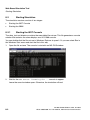
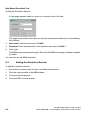
8 Web Based Simulation Tool . . . . . . . . . . . . . . . . . . . . . . . . . . . . . . . . . . . . . . . . . . . . . 8-1
8.1 Installation . . . . . . . . . . . . . . . . . . . . . . . . . . . . . . . . . . . . . . . . . . . . . . . . . . . . . . . . . . . 8-1
8.1.1 General information . . . . . . . . . . . . . . . . . . . . . . . . . . . . . . . . . . . . . . . . . . . . . . . . 8-1
8.1.2 Installation . . . . . . . . . . . . . . . . . . . . . . . . . . . . . . . . . . . . . . . . . . . . . . . . . . . . . . . 8-1
8.2 Starting Simulation . . . . . . . . . . . . . . . . . . . . . . . . . . . . . . . . . . . . . . . . . . . . . . . . . . . . 8-2
8.2.1 Starting the WST Console . . . . . . . . . . . . . . . . . . . . . . . . . . . . . . . . . . . . . . . . . . . 8-2
8.2.2 Starting the WBM . . . . . . . . . . . . . . . . . . . . . . . . . . . . . . . . . . . . . . . . . . . . . . . . . . 8-3
8.3 Ending the Simulation Session . . . . . . . . . . . . . . . . . . . . . . . . . . . . . . . . . . . . . . . . . . . 8-4
8.4 Sample Applications . . . . . . . . . . . . . . . . . . . . . . . . . . . . . . . . . . . . . . . . . . . . . . . . . . . 8-5
8.4.1 Basic Settings for an Individual Gateway . . . . . . . . . . . . . . . . . . . . . . . . . . . . . . . . 8-5
8.4.2 Basic Settings for Multiple Gateways (Copying the Configuration) . . . . . . . . . . . . 8-5
8.4.3 Basic Settings for Multiple Gateways (Multigateway Administration) . . . . . . . . . . . 8-6
8.4.4 Modifying the Configuration for a Single Gateway . . . . . . . . . . . . . . . . . . . . . . . . . 8-7
8.4.5 Modifying the Configuration for Multiple Gateways (Multigateway Administration) 8-7
8.4.6 Offline Diagnostics . . . . . . . . . . . . . . . . . . . . . . . . . . . . . . . . . . . . . . . . . . . . . . . . . 8-8
8.5 Restrictions . . . . . . . . . . . . . . . . . . . . . . . . . . . . . . . . . . . . . . . . . . . . . . . . . . . . . . . . . . 8-8
8.6 Access to a Gateway . . . . . . . . . . . . . . . . . . . . . . . . . . . . . . . . . . . . . . . . . . . . . . . . . 8-10
9 Technical Concepts . . . . . . . . . . . . . . . . . . . . . . . . . . . . . . . . . . . . . . . . . . . . . . . . . . . . 9-1
9.1 Environmental Requirements for VoIP . . . . . . . . . . . . . . . . . . . . . . . . . . . . . . . . . . . . . 9-1
9.1.1 Environmental Requirements in the LAN . . . . . . . . . . . . . . . . . . . . . . . . . . . . . . . . 9-1
9.1.2 Environmental Requirements in the WAN . . . . . . . . . . . . . . . . . . . . . . . . . . . . . . . 9-2
9.2 Bandwidth Requirements in LAN/WAN Environments . . . . . . . . . . . . . . . . . . . . . . . . . 9-2
9.3 Quality of Service (QoS) . . . . . . . . . . . . . . . . . . . . . . . . . . . . . . . . . . . . . . . . . . . . . . . . 9-9
9.4 Configuration Rules for HG 1500 V8 in HiPath 3000 V6. . . . . . . . . . . . . . . . . . . . . . . 9-13
9.4.1 Static Configuration Rules . . . . . . . . . . . . . . . . . . . . . . . . . . . . . . . . . . . . . . . . . . 9-13
9.4.2 Direct Media Connection . . . . . . . . . . . . . . . . . . . . . . . . . . . . . . . . . . . . . . . . . . . 9-15
9.4.3 Gateway Channels (DSP Channels) . . . . . . . . . . . . . . . . . . . . . . . . . . . . . . . . . . 9-15
9.4.4 ITSP Connection . . . . . . . . . . . . . . . . . . . . . . . . . . . . . . . . . . . . . . . . . . . . . . . . . 9-17
9.4.5 MOH Channels (G.711, G.723, G.729) . . . . . . . . . . . . . . . . . . . . . . . . . . . . . . . . 9-17
0-14
A31003-H3580-M103-2-76A9, 01-2009
HiPath 3000/5000 V8 - HG 1500 V8, Administrator Documentation
bktoc.fm
Nur für den internen Gebrauch
Contents
9.4.6 IP Networking Channels (PBX Networking Channels) . . . . . . . . . . . . . . . . . . . .
9.4.7 Bandwidth Control for IP Networking Channels (PBX Networking Channels) . .
9.4.8 DMC (Direct Media Connection) Channels . . . . . . . . . . . . . . . . . . . . . . . . . . . .
9.4.9 ISDN Routing / PPP Channels . . . . . . . . . . . . . . . . . . . . . . . . . . . . . . . . . . . . . .
9.4.10 Fax/Modem Channels . . . . . . . . . . . . . . . . . . . . . . . . . . . . . . . . . . . . . . . . . . . .
9.4.11 Dynamic Configuration Rules . . . . . . . . . . . . . . . . . . . . . . . . . . . . . . . . . . . . . .
9.4.11.1 Empirical Formula for Dimensioning. . . . . . . . . . . . . . . . . . . . . . . . . . . . . .
9.5 Static and Adaptive Jitter Buffer . . . . . . . . . . . . . . . . . . . . . . . . . . . . . . . . . . . . . . . .
9.5.1 Jitter Buffer Function . . . . . . . . . . . . . . . . . . . . . . . . . . . . . . . . . . . . . . . . . . . . . .
9.5.2 How the Jitter Buffer Works. . . . . . . . . . . . . . . . . . . . . . . . . . . . . . . . . . . . . . . . .
9.5.3 Considerations when Setting the Delay for Static Jitter Buffers . . . . . . . . . . . . .
9.5.4 Clock Drift in Static Jitter Buffers. . . . . . . . . . . . . . . . . . . . . . . . . . . . . . . . . . . . .
9.5.5 Minimum Delay in Adaptive Jitter Buffers . . . . . . . . . . . . . . . . . . . . . . . . . . . . . .
9.5.6 Packet Loss Verification in Adaptive Jitter Buffers . . . . . . . . . . . . . . . . . . . . . . .
9.6 SSL and VPN. . . . . . . . . . . . . . . . . . . . . . . . . . . . . . . . . . . . . . . . . . . . . . . . . . . . . . .
9.6.1 Encryption and Keys . . . . . . . . . . . . . . . . . . . . . . . . . . . . . . . . . . . . . . . . . . . . . .
9.6.2 Certificates . . . . . . . . . . . . . . . . . . . . . . . . . . . . . . . . . . . . . . . . . . . . . . . . . . . . .
9.6.3 IPsec Tunnel . . . . . . . . . . . . . . . . . . . . . . . . . . . . . . . . . . . . . . . . . . . . . . . . . . . .
9.6.4 Services . . . . . . . . . . . . . . . . . . . . . . . . . . . . . . . . . . . . . . . . . . . . . . . . . . . . . . .
9.6.5 Rules . . . . . . . . . . . . . . . . . . . . . . . . . . . . . . . . . . . . . . . . . . . . . . . . . . . . . . . . . .
9.6.6 Authentication . . . . . . . . . . . . . . . . . . . . . . . . . . . . . . . . . . . . . . . . . . . . . . . . . . .
9.6.7 SSL and VPN in HG 1500 . . . . . . . . . . . . . . . . . . . . . . . . . . . . . . . . . . . . . . . . . .
9.7 H.235 Security . . . . . . . . . . . . . . . . . . . . . . . . . . . . . . . . . . . . . . . . . . . . . . . . . . . . . .
9.8 Using SNMP . . . . . . . . . . . . . . . . . . . . . . . . . . . . . . . . . . . . . . . . . . . . . . . . . . . . . . .
9.8.1 SNMP traps. . . . . . . . . . . . . . . . . . . . . . . . . . . . . . . . . . . . . . . . . . . . . . . . . . . . .
9.8.2 SNMP Functions . . . . . . . . . . . . . . . . . . . . . . . . . . . . . . . . . . . . . . . . . . . . . . . . .
9.9 Fault Detection with Traps, Traces, and Events . . . . . . . . . . . . . . . . . . . . . . . . . . . .
9.9.1 Traps . . . . . . . . . . . . . . . . . . . . . . . . . . . . . . . . . . . . . . . . . . . . . . . . . . . . . . . . . .
9.9.2 Traces . . . . . . . . . . . . . . . . . . . . . . . . . . . . . . . . . . . . . . . . . . . . . . . . . . . . . . . . .
9.9.3 Events . . . . . . . . . . . . . . . . . . . . . . . . . . . . . . . . . . . . . . . . . . . . . . . . . . . . . . . . .
9.9.4 Event Log Files . . . . . . . . . . . . . . . . . . . . . . . . . . . . . . . . . . . . . . . . . . . . . . . . . .
9-18
9-18
9-18
9-18
9-20
9-20
9-20
9-20
9-20
9-23
9-25
9-26
9-27
9-28
9-28
9-29
9-30
9-32
9-34
9-34
9-35
9-36
9-37
9-37
9-37
9-41
9-43
9-43
9-44
9-45
9-46
A Terms and Abbreviations . . . . . . . . . . . . . . . . . . . . . . . . . . . . . . . . . . . . . . . . . . . . . . . A-1
B Traces and Events . . . . . . . . . . . . . . . . . . . . . . . . . . . . . . . . . . . . . . . . . . . . . . . . . . . . . B-1
B.1 Traces . . . . . . . . . . . . . . . . . . . . . . . . . . . . . . . . . . . . . . . . . . . . . . . . . . . . . . . . . . . . . B-2
B.1.1 Evaluating Trace Profiles . . . . . . . . . . . . . . . . . . . . . . . . . . . . . . . . . . . . . . . . . . . B-2
B.1.2 Overview: Trace Components . . . . . . . . . . . . . . . . . . . . . . . . . . . . . . . . . . . . . . . B-5
B.1.3 Overview: Trace Profiles. . . . . . . . . . . . . . . . . . . . . . . . . . . . . . . . . . . . . . . . . . . B-10
B.1.4 System Trace . . . . . . . . . . . . . . . . . . . . . . . . . . . . . . . . . . . . . . . . . . . . . . . . . . . B-12
B.1.4.1 Trace Components. . . . . . . . . . . . . . . . . . . . . . . . . . . . . . . . . . . . . . . . . . . . B-12
B.1.4.2 Trace Profiles . . . . . . . . . . . . . . . . . . . . . . . . . . . . . . . . . . . . . . . . . . . . . . . . B-13
B.1.5 OAM/WBM Traces . . . . . . . . . . . . . . . . . . . . . . . . . . . . . . . . . . . . . . . . . . . . . . . B-13
B.1.5.1 Trace Components. . . . . . . . . . . . . . . . . . . . . . . . . . . . . . . . . . . . . . . . . . . . B-13
B.1.5.2 Trace Profiles . . . . . . . . . . . . . . . . . . . . . . . . . . . . . . . . . . . . . . . . . . . . . . . . B-18
A31003-H3580-M103-2-76A9, 01-2009
HiPath 3000/5000 V8 - HG 1500 V8, Administrator Documentation
0-15
bktoc.fm
Contents
Nur für den internen Gebrauch
B.1.6 License Management Trace. . . . . . . . . . . . . . . . . . . . . . . . . . . . . . . . . . . . . . . . .
B.1.6.1 Trace Components . . . . . . . . . . . . . . . . . . . . . . . . . . . . . . . . . . . . . . . . . . . .
B.1.6.2 Trace Profiles . . . . . . . . . . . . . . . . . . . . . . . . . . . . . . . . . . . . . . . . . . . . . . . .
B.1.7 IP Accounting Trace. . . . . . . . . . . . . . . . . . . . . . . . . . . . . . . . . . . . . . . . . . . . . . .
B.1.7.1 Trace Components . . . . . . . . . . . . . . . . . . . . . . . . . . . . . . . . . . . . . . . . . . . .
B.1.7.2 Trace Profiles . . . . . . . . . . . . . . . . . . . . . . . . . . . . . . . . . . . . . . . . . . . . . . . .
B.1.8 GSA Trace . . . . . . . . . . . . . . . . . . . . . . . . . . . . . . . . . . . . . . . . . . . . . . . . . . . . . .
B.1.8.1 Trace Components . . . . . . . . . . . . . . . . . . . . . . . . . . . . . . . . . . . . . . . . . . . .
B.1.8.2 Trace Profiles . . . . . . . . . . . . . . . . . . . . . . . . . . . . . . . . . . . . . . . . . . . . . . . .
B.1.9 CP Trace . . . . . . . . . . . . . . . . . . . . . . . . . . . . . . . . . . . . . . . . . . . . . . . . . . . . . . .
B.1.9.1 Trace Components . . . . . . . . . . . . . . . . . . . . . . . . . . . . . . . . . . . . . . . . . . . .
B.1.9.2 Trace Profiles . . . . . . . . . . . . . . . . . . . . . . . . . . . . . . . . . . . . . . . . . . . . . . . .
B.1.10 SIP-SCN protocol trace . . . . . . . . . . . . . . . . . . . . . . . . . . . . . . . . . . . . . . . . . . .
B.1.10.1 Trace Components . . . . . . . . . . . . . . . . . . . . . . . . . . . . . . . . . . . . . . . . . . .
B.1.10.2 Trace Profiles . . . . . . . . . . . . . . . . . . . . . . . . . . . . . . . . . . . . . . . . . . . . . . .
B.1.11 IP Trunk Support Trace . . . . . . . . . . . . . . . . . . . . . . . . . . . . . . . . . . . . . . . . . . .
B.1.11.1 Trace Components . . . . . . . . . . . . . . . . . . . . . . . . . . . . . . . . . . . . . . . . . . .
B.1.11.2 Trace Profiles . . . . . . . . . . . . . . . . . . . . . . . . . . . . . . . . . . . . . . . . . . . . . . .
B.1.12 H.323 trace. . . . . . . . . . . . . . . . . . . . . . . . . . . . . . . . . . . . . . . . . . . . . . . . . . . . .
B.1.12.1 Trace Components . . . . . . . . . . . . . . . . . . . . . . . . . . . . . . . . . . . . . . . . . . .
B.1.12.2 Trace Profiles . . . . . . . . . . . . . . . . . . . . . . . . . . . . . . . . . . . . . . . . . . . . . . .
B.1.13 Device Manager Trace. . . . . . . . . . . . . . . . . . . . . . . . . . . . . . . . . . . . . . . . . . . .
B.1.13.1 Trace Components . . . . . . . . . . . . . . . . . . . . . . . . . . . . . . . . . . . . . . . . . . .
B.1.13.2 Trace Profiles . . . . . . . . . . . . . . . . . . . . . . . . . . . . . . . . . . . . . . . . . . . . . . .
B.1.14 LDAP Trace . . . . . . . . . . . . . . . . . . . . . . . . . . . . . . . . . . . . . . . . . . . . . . . . . . . .
B.1.14.1 Trace Components . . . . . . . . . . . . . . . . . . . . . . . . . . . . . . . . . . . . . . . . . . .
B.1.14.2 Trace Profiles . . . . . . . . . . . . . . . . . . . . . . . . . . . . . . . . . . . . . . . . . . . . . . .
B.1.15 LANLeg Controller Trace (LLC) . . . . . . . . . . . . . . . . . . . . . . . . . . . . . . . . . . . . .
B.1.15.1 Trace Components . . . . . . . . . . . . . . . . . . . . . . . . . . . . . . . . . . . . . . . . . . .
B.1.15.2 Trace Profiles . . . . . . . . . . . . . . . . . . . . . . . . . . . . . . . . . . . . . . . . . . . . . . .
B.1.16 Media-Payload-Handler-Trace (MPH) . . . . . . . . . . . . . . . . . . . . . . . . . . . . . . . .
B.1.16.1 Trace Components . . . . . . . . . . . . . . . . . . . . . . . . . . . . . . . . . . . . . . . . . . .
B.1.16.2 Trace Profiles . . . . . . . . . . . . . . . . . . . . . . . . . . . . . . . . . . . . . . . . . . . . . . .
B.1.17 SNTPS trace . . . . . . . . . . . . . . . . . . . . . . . . . . . . . . . . . . . . . . . . . . . . . . . . . . .
B.1.17.1 Trace Components . . . . . . . . . . . . . . . . . . . . . . . . . . . . . . . . . . . . . . . . . . .
B.1.18 HIP Trace . . . . . . . . . . . . . . . . . . . . . . . . . . . . . . . . . . . . . . . . . . . . . . . . . . . . . .
B.1.18.1 Trace Components . . . . . . . . . . . . . . . . . . . . . . . . . . . . . . . . . . . . . . . . . . .
B.1.18.2 Trace Profiles . . . . . . . . . . . . . . . . . . . . . . . . . . . . . . . . . . . . . . . . . . . . . . .
B.1.19 DS Adapter Trace . . . . . . . . . . . . . . . . . . . . . . . . . . . . . . . . . . . . . . . . . . . . . . .
B.1.19.1 Trace Components . . . . . . . . . . . . . . . . . . . . . . . . . . . . . . . . . . . . . . . . . . .
B.1.19.2 Trace Profiles . . . . . . . . . . . . . . . . . . . . . . . . . . . . . . . . . . . . . . . . . . . . . . .
B.1.20 Endpoint Registration Handler (ERH) Trace . . . . . . . . . . . . . . . . . . . . . . . . . . .
B.1.20.1 Trace Components . . . . . . . . . . . . . . . . . . . . . . . . . . . . . . . . . . . . . . . . . . .
0-16
B-19
B-19
B-19
B-19
B-19
B-20
B-20
B-20
B-21
B-21
B-21
B-22
B-24
B-24
B-25
B-25
B-25
B-26
B-28
B-28
B-31
B-36
B-36
B-37
B-38
B-38
B-38
B-38
B-38
B-39
B-39
B-39
B-40
B-40
B-40
B-40
B-40
B-41
B-41
B-41
B-41
B-42
B-42
A31003-H3580-M103-2-76A9, 01-2009
HiPath 3000/5000 V8 - HG 1500 V8, Administrator Documentation
bktoc.fm
Nur für den internen Gebrauch
Contents
B.1.20.2 Trace Profiles . . . . . . . . . . . . . . . . . . . . . . . . . . . . . . . . . . . . . . . . . . . . . . . B-43
B.1.21 IPsec Trace. . . . . . . . . . . . . . . . . . . . . . . . . . . . . . . . . . . . . . . . . . . . . . . . . . . . B-43
B.1.21.1 Trace Components. . . . . . . . . . . . . . . . . . . . . . . . . . . . . . . . . . . . . . . . . . . B-43
B.1.21.2 Trace Profiles . . . . . . . . . . . . . . . . . . . . . . . . . . . . . . . . . . . . . . . . . . . . . . . B-44
B.1.22 SW Platform Trace . . . . . . . . . . . . . . . . . . . . . . . . . . . . . . . . . . . . . . . . . . . . . . B-44
B.1.22.1 Trace Components. . . . . . . . . . . . . . . . . . . . . . . . . . . . . . . . . . . . . . . . . . . B-44
B.1.22.2 Trace Profiles . . . . . . . . . . . . . . . . . . . . . . . . . . . . . . . . . . . . . . . . . . . . . . . B-51
B.1.23 DLI trace . . . . . . . . . . . . . . . . . . . . . . . . . . . . . . . . . . . . . . . . . . . . . . . . . . . . . . B-57
B.1.23.1 Trace Components. . . . . . . . . . . . . . . . . . . . . . . . . . . . . . . . . . . . . . . . . . . B-57
B.1.23.2 Trace Profiles . . . . . . . . . . . . . . . . . . . . . . . . . . . . . . . . . . . . . . . . . . . . . . . B-57
B.1.24 P2P trace . . . . . . . . . . . . . . . . . . . . . . . . . . . . . . . . . . . . . . . . . . . . . . . . . . . . . B-57
B.1.24.1 Trace Components. . . . . . . . . . . . . . . . . . . . . . . . . . . . . . . . . . . . . . . . . . . B-57
B.1.25 QDC trace . . . . . . . . . . . . . . . . . . . . . . . . . . . . . . . . . . . . . . . . . . . . . . . . . . . . . B-58
B.1.25.1 Trace Components. . . . . . . . . . . . . . . . . . . . . . . . . . . . . . . . . . . . . . . . . . . B-58
B.1.25.2 Trace Profiles . . . . . . . . . . . . . . . . . . . . . . . . . . . . . . . . . . . . . . . . . . . . . . . B-58
B.1.26 SIP_FM trace (SIP feature manager) . . . . . . . . . . . . . . . . . . . . . . . . . . . . . . . . B-59
B.1.26.1 Trace Components. . . . . . . . . . . . . . . . . . . . . . . . . . . . . . . . . . . . . . . . . . . B-59
B.1.26.2 Trace Profiles . . . . . . . . . . . . . . . . . . . . . . . . . . . . . . . . . . . . . . . . . . . . . . . B-59
B.1.27 SIP trace . . . . . . . . . . . . . . . . . . . . . . . . . . . . . . . . . . . . . . . . . . . . . . . . . . . . . . B-60
B.1.27.1 Trace Components. . . . . . . . . . . . . . . . . . . . . . . . . . . . . . . . . . . . . . . . . . . B-60
B.1.27.2 Trace Profiles . . . . . . . . . . . . . . . . . . . . . . . . . . . . . . . . . . . . . . . . . . . . . . . B-61
B.2 Events . . . . . . . . . . . . . . . . . . . . . . . . . . . . . . . . . . . . . . . . . . . . . . . . . . . . . . . . . . . . B-61
B.2.1 Overview: Event Codes . . . . . . . . . . . . . . . . . . . . . . . . . . . . . . . . . . . . . . . . . . . B-62
B.2.2 Status Events . . . . . . . . . . . . . . . . . . . . . . . . . . . . . . . . . . . . . . . . . . . . . . . . . . . B-77
B.2.3 Reboot Events . . . . . . . . . . . . . . . . . . . . . . . . . . . . . . . . . . . . . . . . . . . . . . . . . . B-80
B.2.4 Resource Monitoring Events. . . . . . . . . . . . . . . . . . . . . . . . . . . . . . . . . . . . . . . . B-84
B.2.5 Routing Events . . . . . . . . . . . . . . . . . . . . . . . . . . . . . . . . . . . . . . . . . . . . . . . . . . B-87
B.2.6 Call Control and Feature Events. . . . . . . . . . . . . . . . . . . . . . . . . . . . . . . . . . . . . B-89
B.2.7 SCN Protocol Events . . . . . . . . . . . . . . . . . . . . . . . . . . . . . . . . . . . . . . . . . . . . . B-93
B.2.8 H.323 Events . . . . . . . . . . . . . . . . . . . . . . . . . . . . . . . . . . . . . . . . . . . . . . . . . . . B-99
B.2.9 H.235 Events . . . . . . . . . . . . . . . . . . . . . . . . . . . . . . . . . . . . . . . . . . . . . . . . . . B-101
B.2.10 RTPQM Events . . . . . . . . . . . . . . . . . . . . . . . . . . . . . . . . . . . . . . . . . . . . . . . . B-102
B.2.11 GSA Events . . . . . . . . . . . . . . . . . . . . . . . . . . . . . . . . . . . . . . . . . . . . . . . . . . B-102
B.2.12 DGW Events . . . . . . . . . . . . . . . . . . . . . . . . . . . . . . . . . . . . . . . . . . . . . . . . . . B-102
B.2.13 CAR Events . . . . . . . . . . . . . . . . . . . . . . . . . . . . . . . . . . . . . . . . . . . . . . . . . . B-112
B.2.14 REG Events . . . . . . . . . . . . . . . . . . . . . . . . . . . . . . . . . . . . . . . . . . . . . . . . . . B-117
B.2.15 NU Events. . . . . . . . . . . . . . . . . . . . . . . . . . . . . . . . . . . . . . . . . . . . . . . . . . . . B-118
B.2.16 NU Leg Control Events . . . . . . . . . . . . . . . . . . . . . . . . . . . . . . . . . . . . . . . . . . B-122
B.2.17 HFA Manager Events . . . . . . . . . . . . . . . . . . . . . . . . . . . . . . . . . . . . . . . . . . . B-122
B.2.18 HFA Adapter Events . . . . . . . . . . . . . . . . . . . . . . . . . . . . . . . . . . . . . . . . . . . . B-128
B.2.19 PPP Call Control Events . . . . . . . . . . . . . . . . . . . . . . . . . . . . . . . . . . . . . . . . . B-129
B.2.20 PPP MANAGER Events . . . . . . . . . . . . . . . . . . . . . . . . . . . . . . . . . . . . . . . . . B-129
B.2.21 PPP Stack Events. . . . . . . . . . . . . . . . . . . . . . . . . . . . . . . . . . . . . . . . . . . . . . B-129
B.2.22 VCAPI Events . . . . . . . . . . . . . . . . . . . . . . . . . . . . . . . . . . . . . . . . . . . . . . . . . B-129
B.2.23 VCAPI Application Events. . . . . . . . . . . . . . . . . . . . . . . . . . . . . . . . . . . . . . . . B-137
A31003-H3580-M103-2-76A9, 01-2009
HiPath 3000/5000 V8 - HG 1500 V8, Administrator Documentation
0-17
bktoc.fm
Contents
Nur für den internen Gebrauch
B.2.24 H.323 Client Events . . . . . . . . . . . . . . . . . . . . . . . . . . . . . . . . . . . . . . . . . . . . .
B.2.25 IPNC Events. . . . . . . . . . . . . . . . . . . . . . . . . . . . . . . . . . . . . . . . . . . . . . . . . . .
B.2.26 IPNCA Events . . . . . . . . . . . . . . . . . . . . . . . . . . . . . . . . . . . . . . . . . . . . . . . . .
B.2.27 MPH Events . . . . . . . . . . . . . . . . . . . . . . . . . . . . . . . . . . . . . . . . . . . . . . . . . . .
B.2.28 OAM Events . . . . . . . . . . . . . . . . . . . . . . . . . . . . . . . . . . . . . . . . . . . . . . . . . . .
B.2.29 CLI Events . . . . . . . . . . . . . . . . . . . . . . . . . . . . . . . . . . . . . . . . . . . . . . . . . . . .
B.2.30 Licence Management Events. . . . . . . . . . . . . . . . . . . . . . . . . . . . . . . . . . . . . .
B.2.31 HIP Events . . . . . . . . . . . . . . . . . . . . . . . . . . . . . . . . . . . . . . . . . . . . . . . . . . . .
B.2.32 SI Events (System Interface Events) . . . . . . . . . . . . . . . . . . . . . . . . . . . . . . . .
B.2.33 MAGIC/Device Manager Events . . . . . . . . . . . . . . . . . . . . . . . . . . . . . . . . . . .
B.2.33.1 Startup and Internal Messages . . . . . . . . . . . . . . . . . . . . . . . . . . . . . . . . .
B.2.33.2 LEG Management Messages . . . . . . . . . . . . . . . . . . . . . . . . . . . . . . . . . .
B.2.33.3 Layer2 Communication Messages . . . . . . . . . . . . . . . . . . . . . . . . . . . . . .
B.2.34 Important Platform Software Status Events . . . . . . . . . . . . . . . . . . . . . . . . . . .
B.2.35 Major ASC Events . . . . . . . . . . . . . . . . . . . . . . . . . . . . . . . . . . . . . . . . . . . . . .
B.2.36 Major ASP Events . . . . . . . . . . . . . . . . . . . . . . . . . . . . . . . . . . . . . . . . . . . . . .
B.2.37 Minor ASP Events . . . . . . . . . . . . . . . . . . . . . . . . . . . . . . . . . . . . . . . . . . . . . .
B.2.38 IP Filter Events. . . . . . . . . . . . . . . . . . . . . . . . . . . . . . . . . . . . . . . . . . . . . . . . .
B.2.39 MAC Filter Events . . . . . . . . . . . . . . . . . . . . . . . . . . . . . . . . . . . . . . . . . . . . . .
B.2.40 IP Stack Events . . . . . . . . . . . . . . . . . . . . . . . . . . . . . . . . . . . . . . . . . . . . . . . .
B.2.41 DELIC Events. . . . . . . . . . . . . . . . . . . . . . . . . . . . . . . . . . . . . . . . . . . . . . . . . .
B.2.42 Test Loadware Events . . . . . . . . . . . . . . . . . . . . . . . . . . . . . . . . . . . . . . . . . . .
B.2.43 Fax Converter, HDLC and X.25 Events . . . . . . . . . . . . . . . . . . . . . . . . . . . . . .
B.2.44 IP Accounting Events . . . . . . . . . . . . . . . . . . . . . . . . . . . . . . . . . . . . . . . . . . . .
B.2.45 Endpoint Registration Handler (ERH) Trace Events . . . . . . . . . . . . . . . . . . . .
B.2.46 IPNCV Events . . . . . . . . . . . . . . . . . . . . . . . . . . . . . . . . . . . . . . . . . . . . . . . . .
B.2.47 XMLUTILS Events . . . . . . . . . . . . . . . . . . . . . . . . . . . . . . . . . . . . . . . . . . . . . .
B.2.48 Error Events . . . . . . . . . . . . . . . . . . . . . . . . . . . . . . . . . . . . . . . . . . . . . . . . . . .
B.2.49 LAN signaling events – CCE . . . . . . . . . . . . . . . . . . . . . . . . . . . . . . . . . . . . . .
B.2.50 Events for LLC operation . . . . . . . . . . . . . . . . . . . . . . . . . . . . . . . . . . . . . . . . .
B.2.51 Client related events . . . . . . . . . . . . . . . . . . . . . . . . . . . . . . . . . . . . . . . . . . . .
B.2.52 QDC CGWA related Events . . . . . . . . . . . . . . . . . . . . . . . . . . . . . . . . . . . . . . .
B.2.53 QDC VoIPSD error report events. . . . . . . . . . . . . . . . . . . . . . . . . . . . . . . . . . .
B.2.54 SIP events . . . . . . . . . . . . . . . . . . . . . . . . . . . . . . . . . . . . . . . . . . . . . . . . . . . .
B-140
B-141
B-142
B-142
B-143
B-146
B-147
B-148
B-151
B-152
B-152
B-158
B-159
B-162
B-162
B-162
B-163
B-163
B-164
B-165
B-165
B-166
B-166
B-168
B-169
B-170
B-170
B-171
B-171
B-171
B-172
B-173
B-173
B-173
C WAN/LAN Management. . . . . . . . . . . . . . . . . . . . . . . . . . . . . . . . . . . . . . . . . . . . . . . . . C-1
C.1 Utility Programs for TCP/IP Diagnostics. . . . . . . . . . . . . . . . . . . . . . . . . . . . . . . . . . . . C-1
C.1.1 ping . . . . . . . . . . . . . . . . . . . . . . . . . . . . . . . . . . . . . . . . . . . . . . . . . . . . . . . . . . . . C-1
C.1.2 ipconfig. . . . . . . . . . . . . . . . . . . . . . . . . . . . . . . . . . . . . . . . . . . . . . . . . . . . . . . . . . C-2
C.1.3 nslookup. . . . . . . . . . . . . . . . . . . . . . . . . . . . . . . . . . . . . . . . . . . . . . . . . . . . . . . . . C-4
C.1.4 Host name . . . . . . . . . . . . . . . . . . . . . . . . . . . . . . . . . . . . . . . . . . . . . . . . . . . . . . . C-5
C.1.5 netstat . . . . . . . . . . . . . . . . . . . . . . . . . . . . . . . . . . . . . . . . . . . . . . . . . . . . . . . . . . C-5
C.1.6 nbtstat . . . . . . . . . . . . . . . . . . . . . . . . . . . . . . . . . . . . . . . . . . . . . . . . . . . . . . . . . . C-9
C.1.7 pathping . . . . . . . . . . . . . . . . . . . . . . . . . . . . . . . . . . . . . . . . . . . . . . . . . . . . . . . . C-10
C.1.8 route. . . . . . . . . . . . . . . . . . . . . . . . . . . . . . . . . . . . . . . . . . . . . . . . . . . . . . . . . . . C-11
0-18
A31003-H3580-M103-2-76A9, 01-2009
HiPath 3000/5000 V8 - HG 1500 V8, Administrator Documentation
bktoc.fm
Nur für den internen Gebrauch
Contents
C.1.9 tracert . . . . . . . . . . . . . . . . . . . . . . . . . . . . . . . . . . . . . . . . . . . . . . . . . . . . . . . . .
C.1.10 ARP . . . . . . . . . . . . . . . . . . . . . . . . . . . . . . . . . . . . . . . . . . . . . . . . . . . . . . . . .
C.1.11 telnet . . . . . . . . . . . . . . . . . . . . . . . . . . . . . . . . . . . . . . . . . . . . . . . . . . . . . . . . .
C.1.12 Unwanted Internet Connections (DNS Queries). . . . . . . . . . . . . . . . . . . . . . . .
C.2 IP Addressing: Subnets. . . . . . . . . . . . . . . . . . . . . . . . . . . . . . . . . . . . . . . . . . . . . . .
C-12
C-13
C-14
C-14
C-15
D The CLI Command Interface . . . . . . . . . . . . . . . . . . . . . . . . . . . . . . . . . . . . . . . . . . . . . D-1
D.1 List of All CLI Commands . . . . . . . . . . . . . . . . . . . . . . . . . . . . . . . . . . . . . . . . . . . . . . D-1
D.2 General commands . . . . . . . . . . . . . . . . . . . . . . . . . . . . . . . . . . . . . . . . . . . . . . . . . . . D-4
D.2.1 Shell Commands . . . . . . . . . . . . . . . . . . . . . . . . . . . . . . . . . . . . . . . . . . . . . . . . . D-4
D.2.2 Interrupting the Boot Procedure . . . . . . . . . . . . . . . . . . . . . . . . . . . . . . . . . . . . . . D-5
D.3 Authentication . . . . . . . . . . . . . . . . . . . . . . . . . . . . . . . . . . . . . . . . . . . . . . . . . . . . . . . D-5
D.4 Configuration . . . . . . . . . . . . . . . . . . . . . . . . . . . . . . . . . . . . . . . . . . . . . . . . . . . . . . . . D-6
D.4.1 Installation Commands . . . . . . . . . . . . . . . . . . . . . . . . . . . . . . . . . . . . . . . . . . . . . D-6
D.4.2 Configuration Commands . . . . . . . . . . . . . . . . . . . . . . . . . . . . . . . . . . . . . . . . . . . D-6
D.5 Maintenance . . . . . . . . . . . . . . . . . . . . . . . . . . . . . . . . . . . . . . . . . . . . . . . . . . . . . . . . D-9
D.5.1 Inspection . . . . . . . . . . . . . . . . . . . . . . . . . . . . . . . . . . . . . . . . . . . . . . . . . . . . . . . D-9
D.5.2 Resetting the Gateway . . . . . . . . . . . . . . . . . . . . . . . . . . . . . . . . . . . . . . . . . . . . D-11
D.6 Security commands. . . . . . . . . . . . . . . . . . . . . . . . . . . . . . . . . . . . . . . . . . . . . . . . . . D-12
D.6.1 SSL Functions . . . . . . . . . . . . . . . . . . . . . . . . . . . . . . . . . . . . . . . . . . . . . . . . . . D-12
D.6.2 Enabling and Disabling IPsec . . . . . . . . . . . . . . . . . . . . . . . . . . . . . . . . . . . . . . . D-13
D.7 Start command line . . . . . . . . . . . . . . . . . . . . . . . . . . . . . . . . . . . . . . . . . . . . . . . . . . D-13
D.7.1 Rebooting . . . . . . . . . . . . . . . . . . . . . . . . . . . . . . . . . . . . . . . . . . . . . . . . . . . . . . D-14
D.7.1.1 Initiating Reboot . . . . . . . . . . . . . . . . . . . . . . . . . . . . . . . . . . . . . . . . . . . . . . D-14
D.7.1.2 Boot sequence . . . . . . . . . . . . . . . . . . . . . . . . . . . . . . . . . . . . . . . . . . . . . . . D-14
D.7.1.3 Interrupting the Boot Procedure . . . . . . . . . . . . . . . . . . . . . . . . . . . . . . . . . . D-15
D.7.2 Controlling the Boot Procedure. . . . . . . . . . . . . . . . . . . . . . . . . . . . . . . . . . . . . . D-15
D.7.2.1 Boot Commands . . . . . . . . . . . . . . . . . . . . . . . . . . . . . . . . . . . . . . . . . . . . . D-15
D.7.2.2 Start Parameters . . . . . . . . . . . . . . . . . . . . . . . . . . . . . . . . . . . . . . . . . . . . . D-17
D.7.2.3 Editing Start Parameters . . . . . . . . . . . . . . . . . . . . . . . . . . . . . . . . . . . . . . . D-18
D.7.3 Software Installation using the Boot CLI. . . . . . . . . . . . . . . . . . . . . . . . . . . . . . . D-18
D.7.3.1 Preparations. . . . . . . . . . . . . . . . . . . . . . . . . . . . . . . . . . . . . . . . . . . . . . . . . D-18
D.7.3.2 Loading the Software to the Flash Memory . . . . . . . . . . . . . . . . . . . . . . . . . D-19
E Internet References . . . . . . . . . . . . . . . . . . . . . . . . . . . . . . . . . . . . . . . . . . . . . . . . . . . . E-1
E.1 RFCs . . . . . . . . . . . . . . . . . . . . . . . . . . . . . . . . . . . . . . . . . . . . . . . . . . . . . . . . . . . . . . E-1
E.2 Other Sources . . . . . . . . . . . . . . . . . . . . . . . . . . . . . . . . . . . . . . . . . . . . . . . . . . . . . . . E-3
F Index . . . . . . . . . . . . . . . . . . . . . . . . . . . . . . . . . . . . . . . . . . . . . . . . . . . . . . . . . . . . . . . . F-1
A31003-H3580-M103-2-76A9, 01-2009
HiPath 3000/5000 V8 - HG 1500 V8, Administrator Documentation
0-19
bktoc.fm
Contents
0-20
Nur für den internen Gebrauch
A31003-H3580-M103-2-76A9, 01-2009
HiPath 3000/5000 V8 - HG 1500 V8, Administrator Documentation
hg-01.fm
Nur für den internen Gebrauch
1
Introduction
Target Audience
Introduction
This document describes the configuration of HiPath 3000/5000 V8 - HG 1500 V8 and the tools
available for it.
This chapter provides an overview of this manual. It describes:
●
this manual’s target audience (see Section 1.1, "Target Audience"),
●
the contents of each chapter in this manual (see Section 1.2, "Contents of this Manual"),
●
the typographical conventions used (see Section 1.3, "Conventions Used").
1.1
Target Audience
This manual is intended for administrators who are responsible for the configuration of HiPath
3000/5000 V8 - HG 1500 V8. They should have experience in LAN administration and be familiar with the following areas:
●
Data communications hardware
●
WAN (Wide Area Network) concepts and terms
●
LAN (Local Area Network) concepts and terms
●
Internet concepts and terms
You should have received instructions from Siemens on the following:
●
Installing and Starting Up HiPath 3000/5000 V8 - HG 1500 V8
●
Configuring HiPath 3000/5000 V8 - HG 1500 V8 VoIP Functions
●
Configuring and Customizing HiPath 3000/5000 V8 - HG 1500 V8 Data Communication
Parameters
1.2
Contents of this Manual
This manual offers a full description of administration options for HG 1500 and also contains
background information on selected topics.
It explains how the HiPath 3000/5000 V8 - HG 1500 V8 is to be administered after being installed in a subrack.
Initial setup must be performed at the start of administration. The necessary pre-administration
steps are described in Chapter 2.
Further information on HiPath 3000/5000 V8 - HG 1500 V8 may be found in the HiPath 3000
Service Manual and the HiPath 3000 System Description.
A31003-H3580-M103-2-76A9, 01-2009
HiPath 3000/5000 V8 - HG 1500 V8, Administrator Documentation
1-1
hg-01.fm
Introduction
Contents of this Manual
Nur für den internen Gebrauch
Subsequent chapters provide a systematic description of the WBM interface for configuring and
administering HiPath 3000/5000 V8 - HG 1500 V8.
No. Chapter
Contents
1
Introduction
Defines the target audience and provides an overview
of the documentation structure.
2
Preparing the Board
Lists the prerequisites for HG 1500 administration via
WBM.
3
WBM
Describes the basic operating elements of the WBM
user interface.
4
Front panel
Describes how to use the WBM module "Front panel",
which allows the board operating functions to be monitored.
5
Wizard
Describes how to use the WBM module "Wizards" using the wizard for initial configuration.
6
Maintenance
Describes the use of the WBM module "Maintenance",
for which a broad range of administration options is
available.
7
Explorers
Describes the use of the WBM module "Explorers", for
which numerous board settings are available.
8
Web Based Simulation Tool
Describes the installation and implementation of the
WST.
9
Technical Concepts
Contains background data on board configuration options.
A
Terms and Abbreviations
Contains brief information on relevant terms and abbreviations.
B
Traces and Events
Documents possible trace and event messages
C
WAN/LAN Management
Describes TCP/IP commands under MS Windows, basic principles of IP network addressing, standard port
numbers, etc.
D
Internet References
The listed Internet sources provide original or detailed
information on technical standards used in HG 1500.
E
The CLI Command Interface
Describes possible CLI commands for board configuration via terminal.
F
Index
Index
Table 1-1
1-2
Chapter Overview
A31003-H3580-M103-2-76A9, 01-2009
HiPath 3000/5000 V8 - HG 1500 V8, Administrator Documentation
hg-01.fm
Nur für den internen Gebrauch
1.3
Introduction
Conventions Used
Conventions Used
The following display conventions are used in this manual:
Convention
Example
Courier
Input and output
Example: Enter LOCAL as the file name.
Command not found
Italics
Variable
Example: Name can contain up to eight characters.
Italics
Indicates user interface elements
Example: Click OK
Select Exit from the File menu.
Bold
Special emphasis
Example: This name must not be deleted.
<Courier>
Keyboard shortcuts
Example: <CTRL>+<ALT>+<ESC>
>
Menu sequence
Example: File > Exit.
Conventions Used
Cross-reference or hyperlink
>
Additional information
7
Warning of critical points in a procedure.
Table 1-2
Typographic Conventions
A31003-H3580-M103-2-76A9, 01-2009
HiPath 3000/5000 V8 - HG 1500 V8, Administrator Documentation
1-3
hg-01.fm
Introduction
Conventions Used
1-4
Nur für den internen Gebrauch
A31003-H3580-M103-2-76A9, 01-2009
HiPath 3000/5000 V8 - HG 1500 V8, Administrator Documentation
hg-02.fm
Nur für den internen Gebrauch
2
Preparing the Board
Starting the HG 1500
Preparing the Board
Notes on how to install the HG 3550/3540 V2.0 may be found in the corresponding AMO STMIB
service manual or the HiPath 4000 HiPath Manager.
Once the HiPath HG 1500 has been installed, it must be started and configured for HTTP access via WBM. The start-up procedure and configuration options are described in this chapter.
>
2.1
If you are using the HiPath HG 1500 for an Internet connection:
An Internet connection always involves an elevated security risk. In order to keep
risks to a minimum, we therefore recommend installing and using a security solution
that satisfies security requirements.
Starting the HG 1500
When the system is started, the HiPath HG 1500 is automatically started as well. This initiates
the firmware start routine, the gateway self test and the startup procedure.
2.1.1
Firmware Start Routine
The firmware is located in the flash memory and is started each time the system is rebooted.
The firmware code resets the system and is the first code to be run when the power supply is
switched on.
The firmware performs the following functions:
1.
Initializes the hardware components of the board.
2.
Tests the hardware components (Built-In Self-test BIST).
3.
Creates the file system in the flash memory.
4.
Activates the CLI handler).
5.
Loads data from the flash memory (loading program).
6.
Starts the application program.
The automatic boot procedure between steps 4 and 5 and can be interrupted, as described in
Section 2.1.3, "Interrupting the Boot Procedure".
If the boot procedure is not interrupted, the gateway continues the boot procedure and can then
be configured.
A31003-H3580-M103-2-76A9, 01-2009
HiPath 3000/5000 V8 - HG 1500 V8, Administrator Documentation
2-1
hg-02.fm
Preparing the Board
Configuring the HiPath HG 1500
2.1.2
Nur für den internen Gebrauch
LED Startup Display
If there is no terminal connected to the V.24 interface of the board, the LEDs at the front of the
HiPath HG 1500 display the main steps of the start routine.
The red LED remains illuminated at the beginning of the boot procedure. Once code loading
has been initiated (see Section 2.1.1, "Firmware Start Routine", step 5), the red power supply
LED flashes once per second. Once the LED has stopped flashing, the boot procedure is complete.
The gateway is operational approximately 30 s after the LED goes out.
>
2.1.3
If a serial terminal is connected, the text "System Running" is displayed on the terminal as soon as the gateway is ready.
Interrupting the Boot Procedure
The boot procedure can be interrupted after the self-test by pressing any key on the terminal
within three seconds of the Press any key to Stop autoboot message appearing on the screen.
If the boot procedure is interrupted in this way, the device switches to a special mode in which
the system may have been configured to request the root administrator’s password. In this
case, enter the password. Access via Boot CLI is granted after logon. With boot CLI, booting
can be manually controlled by entering boot commands and changing the start parameters.
The boot CLI commands are described in the Section D.7, "Start command line".
To repeat the standard boot procedure, press <CTRL>+X.
2.2
Configuring the HiPath HG 1500
Before the HiPath HG 1500 can be administered, an IP address must be assigned to the
board’s LAN1 interface. The IP addresses can be assigned via CLI. Do this by connecting an
appropriate terminal to the HiPath HG 1500’s V.24 interface. Using CLI commands, you can
configure IP addresses, subnet masks and default routers (for a detailed description, see Section 2.2.1, "Configuration via CLI Interface").
Once the HiPath HG 1500 has been assigned an IP address and has been rebooted, you can
boot the board WBM via a Web browser in the network (see Chapter 3, "WBM").
>
2-2
Information about the IP protocols and port numbers used in HiPath 2000 V1.0 can
be found in Appendix C of the HiPath 2000 Service Manual.
A31003-H3580-M103-2-76A9, 01-2009
HiPath 3000/5000 V8 - HG 1500 V8, Administrator Documentation
hg-02.fm
Nur für den internen Gebrauch
2.2.1
Preparing the Board
Configuring the HiPath HG 1500
Configuration via CLI Interface
Configuring CLI:
1.
Connect a serial terminal or a PC with a VT 340 terminal emulation program (e.g. HyperTeminal) to the HiPath HG 1500 V.24 interface.
The connection requires the following settings:
Baud rate: 19200, Data: 8 bit, Parity: none, Stop bits: 1, Data flow control: none.
2.
Start the HiPath 3000 system.
3.
Press any key to display the please log in prompt. Log on by entering the user name
and password. The user name and password are specified in the HiPath 3000 system using HiPath 3000 Manager E.
4.
Activate the write access:
get write access
If the command is correct, OK is displayed.
The same applies to all subsequent entries.
Assigning an IP address to the HiPath HG 1500 LAN1 interface:
1.
Set up the gateway IP address (LAN1 interface) by entering the following:
set ip address xxx.xxx.xxx.xxx
where xxx.xxx.xxx.xxx is the IP address (number).
2.
Set up the subnet mask for the gateway by entering:
set ip subnet yyy.yyy.yyy.yyy
where yyy.yyy.yyy.yyy is the address mask.
Example of a Class C subnet:
255.255.255.0
Saving entries and rebooting the HiPath HG 1500:
1.
Save the configuration by entering the following:
save configuration
2.
Start the gateway by entering:
reset
A31003-H3580-M103-2-76A9, 01-2009
HiPath 3000/5000 V8 - HG 1500 V8, Administrator Documentation
2-3
hg-02.fm
Preparing the Board
Configuring the HiPath HG 1500
Nur für den internen Gebrauch
Assigning a default router:
1.
Assign a default router to the gateway by entering:
set Default Gateway zzz.zzz.zzz.zzz
where zzz.zzz.zzz.zzz is the IP address of the router in the customer network.
2.
Re-save the configuration with:
save configuration
2.2.2
Configuration via HiPath 3000 Manager E
To access the gateway via PPP using any connection (analog or ISDN), a PSTN peer with an
activated service entry must be created.
If the HiPath HG 1500 database is empty, service entries can be automatically created using
HiPath 3000 Manager E. The following service entries are possible:
●
Service entry for remote access via an asynchronous modem (V.34).
●
Service entry for remote access via an ISDN card (HDLC).
Working in HiPath 3000 Manager E:
1.
Reading the HiPath 3000 customer database memory (CDB):
File > Transfer > Read/write database > System > PC.
2.
Configure S0 subscribers (e. g., with one of the following values):
3.
HiPath 3800
748
HiPath 3550
686
HiPath 3350
69
Reading out board information:
File > Transfer > Maintenance > Restart/reload > Read card information.
All gateways and slot specifications are listed in the HXG – Remote Initial Startup section.
Under DID for the relevant gateway, enter the extension that you configured in step 2.
4.
Click Accept data.
A PSTN peer is then automatically configured on the HiPath HG 1500 with the following
parameters:
2-4
Peer Name
Remote default
IP Address of PSTN Peer
10.186.237.64
IP Address of Local PSTN Interface
10.186.237.63
A31003-H3580-M103-2-76A9, 01-2009
HiPath 3000/5000 V8 - HG 1500 V8, Administrator Documentation
hg-02.fm
Preparing the Board
Configuring the HiPath HG 1500
Nur für den internen Gebrauch
5.
MSN/DID Number
Specified DID
V.34 Peer
Yes
V.110 Peer
No
CHAP Authentication Mode
CHAP Host
CHAP Password
HiPath 3000 Manager E password
PPP User name
HiPath 3000 Manager E user name
Optionally, the same procedure can be repeated with an additional S0 station number (Recommended value: HiPath 3800 = 749, HiPath 3550 = 687, HiPath 3350 = 70). A second
PSTN peer is then automatically configured with the following parameters:
Peer Name
Remote ISDN
IP Address of PSTN Peer
10.186.237.66
IP Address of Local PSTN Interface
10.186.237.65
MSN/DID Number
Specified DID
V.34 Peer
No
V.110 Peer
No
CHAP Authentication Mode
CHAP Host
CHAP Password
HiPath 3000 Manager E password
PPP User name
HiPath 3000 Manager E user name
Configuring the access PC:
Set up the following dial-up connection on a PC with a modem or an ISDN card:
Connection Type
Internet
Station number
MSN of the PSTN peer entry
Connect via
Modem or ISDN card
Type of dial-up server
PPP
Request password
(CHAP: encrypted,
PAP: unencrypted)
Yes
User name
User name as specified in HiPath 3000 Manager E
ID
ID as specified in HiPath 3000 Manager E
A31003-H3580-M103-2-76A9, 01-2009
HiPath 3000/5000 V8 - HG 1500 V8, Administrator Documentation
2-5
hg-02.fm
Preparing the Board
Configuring the HiPath HG 1500
Nur für den internen Gebrauch
Establishing the connection to the HiPath HG 1500:
If you have selected the proxy server option in the Web browser: Add the Gateway IP address
to the proxy settings for which there is no proxy server being used.
Example:
Asynchronous connection
10.186.237.63
HDLC connection
10.186.237.65
You can now administer the board via the WBM. The address of the example given above is:
Asynchronous connection
http://10.186.237.63:8085
HDLC connection
http://10.186.237.65:8085
2-6
A31003-H3580-M103-2-76A9, 01-2009
HiPath 3000/5000 V8 - HG 1500 V8, Administrator Documentation
hg-03.fm
Nur für den internen Gebrauch
3
WBM
WBM
WBM stands for Web Based Management. The WBM is the default administration interface in
HG 1500.
Any PC with a TCP/IP-supported network connection and a compatible web browser can access the WBM user interface after successfully logging on. The WBM features an integrated
Web server so that the WBM can be accessed over an HTTP URL (or an HTTPS URL if SSL
is enabled).
The WBM user interface is available in German and English. The language can be set via the
Web browser’s language setting.
Hardware requirements:
To operate WBM, you will need a PC with the following minimum requirements:
●
128 MB main memory (RAM),
●
400 MHz processor speed,
●
a mouse with left and right buttons.
Software requirements:
WBM is composed of HTML/XSL pages with frames. To use it, the following must be installed:
●
Windows NT 4.0, 2000 or XP
●
Microsoft Internet Explorer 5.5 or 6.0
●
Java Plug-In JRE 1.3.1,
●
XML Extension DLL V3.0 SP2 or SP4,
●
The following settings must be made in Microsoft Internet Explorer:
–
Allow use of ActiveX and Java
–
Activate the following option: Tools -> Internet options -> Advanced -> Empty temporary Internet files when browser is closed
–
The administration PC may not be connected to the gateway via a proxy server. Therefore activate the following option if necessary: Tools -> Internet options -> Connections
-> LAN settings: Settings... -> Proxy server: Bypass proxy server for local addresses
A31003-H3580-M103-2-76A9, 01-2009
HiPath 3000/5000 V8 - HG 1500 V8, Administrator Documentation
3-1
hg-03.fm
WBM
Starting WBM
>
Nur für den internen Gebrauch
If a DNS server is configured on the administration PC but is not reachable, the WBM
interface operates at a considerably slower speed, especially when loading Java applets. If you experience a situation like this, check the DNS server set in the Administration PC’s network settings. Remove unreachable DNS servers or enter reachable servers.
Miscellaneous requirements:
HiPath HG 1500 must be configured and started. All activities described in Chapter 2, "Preparing the Board" must have been performed.
Overview
You can activate the WBM from the Web browser – see Section 3.1, "Starting WBM". You can
administer all accessible board parameters over the Web-based interface – see Section 3.2,
"WBM Application Interface". A CLI access can also be used for a number of parameters – see
Section 3.3, "Alternative Management over CLI (Console)".
You can also call up information on the board’s integrated SNMP agents using SNMP Management software – see Section 3.4, "SNMP Management".
In addition to the WBM, the HiPath 3000 Manager E is also provided for overall system administration – see Section 3.5, "HiPath Management with HiPath 3000 Manager E".
3.1
Starting WBM
User Account
The "Administrator" user ID is available for use with WBM. This ID enables you to access configuration settings. You can use the initial installation wizard to configure several basic settings.
The default user name and password is: 31994. You may change this default data.
3-2
A31003-H3580-M103-2-76A9, 01-2009
HiPath 3000/5000 V8 - HG 1500 V8, Administrator Documentation
hg-03.fm
Nur für den internen Gebrauch
WBM
Starting WBM
Starting the WBM session
Close all browser windows before you start a new WBM session. To activate WBM on HG 1500:
1.
Open the Internet Explorer. Note the language setting: If you want to use the WBM in English, the language setting for the browser (menu Tools > Internet Options > Language)
must be set first to English (USA) [en-us].
2.
Enter the IP address assigned to the HiPath HG 1500 as the URL:
http://num.num.num.num:8085 (where num is a number between 0 and 255).
A login page with the following fields appears when you log on to a session for the first time:
3.
Username: Enter the default user name.
4.
Password: Enter the default password.
As soon as you have been successfully authenticated, a cookie containing your user name
and expiration date will be saved on your PC. From then on, the cookie is used for WBM
access authentication. If no valid cookie is found, the login window will reappear.
>
5.
For security purposes, individual user accounts should be set up. Real security cannot be guaranteed as long as you are only using the predefined user account. User
accounts are administered in HiPath Manager 3000 E.
Click Login.
The WBM download operation begins. Wait until the WBM home page has been completely loaded.
>
Up to five sessions can be active simultaneously. An attempt to open a sixth session
is denied with a message stating that five sessions are already active. The local
management application issues a warning if another session already has write access when write access is requested. The options available to administrators are not
restricted by this, however. We therefore urge you to take organizational measures
to ensure that no two administrators attempt to process the same object simultaneously.
Ending WBM:
See Section 3.2.1.6, "Logoff".
A31003-H3580-M103-2-76A9, 01-2009
HiPath 3000/5000 V8 - HG 1500 V8, Administrator Documentation
3-3
hg-03.fm
WBM
WBM Application Interface
3.2
Nur für den internen Gebrauch
WBM Application Interface
The main window in WBM consists of the following areas:
Menu area
Module area
Dialog area
Tree structure for selecting functions linked to the
Maintenance and Explorers modules
Control area
Module area:
The area under the banner displays the modules available. You can select the required module
by clicking its name. See Section 3.2.1, "Modules".
Menu area:
The area at the left is used for navigating within a module. The menus that are displayed here
vary depending on the module selected.
3-4
A31003-H3580-M103-2-76A9, 01-2009
HiPath 3000/5000 V8 - HG 1500 V8, Administrator Documentation
hg-03.fm
Nur für den internen Gebrauch
WBM
WBM Application Interface
Control area:
The icons for controlling WBM and the status information that is constantly displayed are located at the bottom. For information on the meaning of the icons, see Section 3.2.2, "Icons in the
WBM Window’s Control Area".
Tree structure for selecting functions linked to the "Maintenance" and "Explorers"
modules
This area displays an Explorers-type tree structure where you can select individual functions.
3.2.1
Modules
The area under the banner displays the modules available. You can select the required module
by clicking its name.
The module’s name is displayed in red italics when activated and module-specific options appear in the menu area.
Modules available:
> Front Panel
> Wizards
> Explorers
> Maintenance
> Help
> Logoff
3.2.1.1
Front Panel
In this module, you can monitor the general functions of the gateway using a schematic view of
the front panel. The status information is displayed with LEDs.
WBM path:
WBM > Front panel
A diagram of the board’s front panel is displayed, see Chapter 4, "Front panel".
A31003-H3580-M103-2-76A9, 01-2009
HiPath 3000/5000 V8 - HG 1500 V8, Administrator Documentation
3-5
hg-03.fm
WBM
WBM Application Interface
3.2.1.2
Nur für den internen Gebrauch
Wizards
The Wizards module for the initial setup combines all operations required for initial gateway
configuration. It guides you through the procedure step by step so that all the required settings
are performed.
WBM path:
WBM > Wizards
The Wizards module’s options are displayed on the left.
Options in the Wizards module:
> Initial Setup
For a detailed description of the functions of the Wizards module, see Chapter 5, "Wizard".
3.2.1.3
Explorers
This module contains all the functions necessary for configuring HG 1500.
WBM path:
WBM > Explorers
The Explorers module’s options are displayed on the left.
Options in the Explorers module:
> Basic Settings
> Security
> Network Interfaces
> Routing
> Voice Gateway
> VCAPI
> Payload
> Statistics
For a detailed description of the functions of the Explorers module, see Chapter 7, "Explorers".
3-6
A31003-H3580-M103-2-76A9, 01-2009
HiPath 3000/5000 V8 - HG 1500 V8, Administrator Documentation
hg-03.fm
Nur für den internen Gebrauch
3.2.1.4
WBM
WBM Application Interface
Maintenance
This module contains all the functions necessary for HG 1500 maintenance and administration.
WBM path:
WBM > Maintenance
The Maintenance module’s options are displayed on the left.
Options in the Maintenance module:
> Configuration
> Software Image
> Firmware
> Multigateway Administration
> Job List
> Traces
> Events
> SNMP
> Admin Log
> Actions
For a detailed description of the functions of the Maintenance module, see Chapter 6, "Maintenance".
3.2.1.5
Help
This module offers the following options:
> About WBM (information page)
> HG 1500 Docu (online help on WBM)
> HiPath home page (link to the Siemens Web range of HiPath solutions)
All references are displayed in a new browser window. The browser window containing the
WBM remains open. You can have both windows open simultaneously and switch from one to
the other over the Windows task bar.
>
Where applicable, the online help storage location must be configured using the
WBM (see Section 7.1.10.2, "Edit Online Help Directory").
A31003-H3580-M103-2-76A9, 01-2009
HiPath 3000/5000 V8 - HG 1500 V8, Administrator Documentation
3-7
hg-03.fm
WBM
WBM Application Interface
3.2.1.6
Nur für den internen Gebrauch
Logoff
Click Logoff to terminate the connection to the gateway and close the WBM session. To save
all configuration changes permanently, click the Save icon in the control area before logging off
(see Section 3.2.2, "Icons in the WBM Window’s Control Area").
WBM path:
WBM > Logoff
If you have not saved your configuration changes or reset the board before logging off (the corresponding Icons in the WBM Window’s Control Area are red), the following warning is displayed:
You modified data which has not yet been saved. In order to save your
data or reboot you must login to WBM again.
Confirm this warning with OK. The logoff procedure resumes and finishes. You are now logged
off the telephone system. Even if you have logged off, WBM still expects modified data to be
saved. The previous warning is shown again the next time you log on and off.
Automatic logoff:
If you close the browser after you have saved your configuration changes, you are automatically
logged off HG 1500. The following message is displayed:
You have left the WBM page without logoff. You will be logged out automatically form the telephone system.
If you have not yet saved your configuration changes, the previous warning is displayed prior to
this message.
3.2.2
Icons in the WBM Window’s Control Area
The control area is an applet that constantly provides control and status information. The figure
below shows an example:
(1)
(2)
(3)
(4)
(5)
(6)
(7)
(8)
Not all the control icons are always active. Inactive icons are grayed out.
The following control icons are available:
●
Padlock icon (1),
●
Save icon (2),
●
Reset icon (3),
3-8
A31003-H3580-M103-2-76A9, 01-2009
HiPath 3000/5000 V8 - HG 1500 V8, Administrator Documentation
hg-03.fm
Nur für den internen Gebrauch
●
WBM
WBM Application Interface
Activity icon (4).
The following status information is also displayed:
●
Status of SSL and IPsec security functions (5),
●
Zustandsinformation der Sicherheitsfunktionen SSL (5),
●
Access category of the user and system version (6),
●
System name and location (7),
●
System date and time, and how long since the last restart (8).
Padlock icon (1)
This icon indicates the current write access status for the administered gateway. The following
two statuses are possible:
Data input is blocked. You can read data but you cannot enter or modify it.
Data can be entered. You have read and write access.
The gateway status changes when the padlock icon is clicked.
If data input is blocked, clicking the icon will immediately activate write access from this PC,
provided that no other administrator currently has write access.
If data input is blocked and write access is currently activated at another PC, a warning message will be displayed when you click the Padlock icon. The program queries whether write access should be transferred to this administrator. If Yes is clicked, write access will be transferred
from another PC to this administrator’s computer.
If you click the Padlock icon while write access is still active on the current PC, write access will
be granted, regardless of whether data has been saved. If data has yet to be saved and/or a
restart is required but has not yet been performed, the relevant control icons will indicate the
present status when write access is next activated.
A31003-H3580-M103-2-76A9, 01-2009
HiPath 3000/5000 V8 - HG 1500 V8, Administrator Documentation
3-9
hg-03.fm
WBM
WBM Application Interface
Nur für den internen Gebrauch
Save icon (2)
This icon saves modified data. It can assume three statuses:
Data input is blocked. Users can read data, but they cannot edit entries.
Data can be entered but no changes have yet been made. (Data in the RAM
is identical to that in the flash memory.)
Data can be entered. Data has been modified but not saved. (Data in the RAM
differs from that in the flash memory.)
Changes are always made to the configuration that was active at the start of the session or to
the last configuration saved during the session. The modified configuration in the RAM is saved
as a new configuration in the flash memory.
Reset icon (3)
This icon triggers a gateway restart. It can assume three statuses:
Data input is blocked. Users can read data, but they cannot edit entries.
Data input is active but no restart is required.
Data input is active. Data has been modified. The gateway must be restarted
to activate the modified configuration.
Clicking the Reset icon will delete any unsaved changes which were made since the start of
the session or since the last time the configuration was saved. A warning is displayed before
unsaved data is deleted. If you click OK, the gateway will restart and the configuration from the
flash memory will overwrite the configuration in the RAM.
Action icon (4)
The icon turns green to indicate a live connection to the HG 1500 Web server. The icon flashes
red when there is no connection set up.
3-10
A31003-H3580-M103-2-76A9, 01-2009
HiPath 3000/5000 V8 - HG 1500 V8, Administrator Documentation
hg-03.fm
Nur für den internen Gebrauch
3.2.3
WBM
WBM Application Interface
Icons in the WBM Tree Representations
The functions available in the Maintenance and Explorers modules are displayed in the contents area in a tree representation similar to Windows Explorer. This tree representation has
the following icons:
●
Directories
Main directory closed. The name of the activated function appears next to
the main directory.
Main directory open. The usable functions and/or additional directories are
displayed under the main directory.
Any directory that contains hidden functions is characterized by a plus sign
(+). A double-click will display these functions.
The functions in this open directory are displayed. A double-click will hide
these functions.
Colors are used in the "Explorers" module under "Security": Red for disabled, green for enabled.
Internet Telephony Service Provider
The color of the bullet point or of the directory indicates the Internet telephony service provider status:
●
Gray bullet point or yellow directory – the provider has been created but
not activated.
●
Green – the provider is activated and registered. No errors have occurred.
●
Orange – the provider is activated but at least one error has occurred in
conjunction with the assigned users.
●
Bullet points
This function can be activated but does not have status information (color:
Gray).
This symbol denotes settings which can be reset to factory defaults (color:
Blue).
This function is active and can be deactivated via a context menu (color:
Green).
A31003-H3580-M103-2-76A9, 01-2009
HiPath 3000/5000 V8 - HG 1500 V8, Administrator Documentation
3-11
hg-03.fm
WBM
WBM Application Interface
Nur für den internen Gebrauch
This function is inactive and can be activated via a context menu (color:
Red).
●
Context menus
A context menu opens when you right-click a directory or bullet point. If a display function
is included in the context menu, you can open this directly by simply clicking the directory
or bullet point.
3-12
A31003-H3580-M103-2-76A9, 01-2009
HiPath 3000/5000 V8 - HG 1500 V8, Administrator Documentation
hg-03.fm
Nur für den internen Gebrauch
3.2.4
WBM
WBM Application Interface
Dialogs and Dialog Elements
Inputs and changes in the WBM are displayed in the browser window as dimmed dialogs within
the browser window. Separate dialog windows can also be displayed, for example, to confirm
a delete request.
The dialogs contain the following typical elements:
Input fields
For entering numeric or alphanumeric values. The relevant field label is displayed before, after or over the field. For security purposes, characters are exclusively displayed as unambiguous symbols, such as stars, in password fields.
Characters unavailable on the keyboard can be inserted using the "Charmap"
character table, for example, under MS Windows.
Selection lists
Click the arrow to open or close the list. Select an entry with a left-click.
Check box
(Here, the upper checkbox is deactivated while the lower one is activated):
The relevant field label is displayed before, after or over the field. Click to activate or deactivate the relevant option.
Radio button
(Here, the upper checkbox is deactivated while the lower one is activated):
Radio buttons are combined in groups where one element is always selected.
The relevant field label is displayed before, after or over the field. Click to activate or deactivate the relevant function.
Buttons
Click to perform the action described by the button’s label text. The texts are
self-explanatory, for example, Send or Delete.
A31003-H3580-M103-2-76A9, 01-2009
HiPath 3000/5000 V8 - HG 1500 V8, Administrator Documentation
3-13
hg-03.fm
WBM
WBM Application Interface
Nur für den internen Gebrauch
The following default buttons are used:
●
Apply: Data or changes entered are buffered in the RAM and, where applicable, verified.
To save entries and changes permanently, click the Save icon in the control area. (see Section 3.2.2, "Icons in the WBM Window’s Control Area").
●
Undo: Data or changes entered in the dialog are discarded. The original status of the dialog
is restored.
●
OK: Positive acknowledgement of separate dialog windows. The selected action is performed if you click this button (no undo available).
●
Cancel: Negative acknowledgement of separate dialog windows. The selected action is
cancelled if you click this button.
●
Next Page: Change to the next Web page within a multi-page dialog. This button is currently only used in wizards (see Chapter 5, "Wizard").
●
Previous Page: Change to the previous Web page within a multi-page dialog. This button
is currently only used in wizards.
3.2.5
Table Editor
A Table Editor is available for a number of functions to simplify the task of processing multiple
data records in one go. The possible parameter inputs are described in detail under the WBM
input windows.
The Table Editor appears in a separate window that can be minimized, maximized or closed
using conventional Windows tools.
Example of an editable table
The following is an example of an editable table:
3-14
A31003-H3580-M103-2-76A9, 01-2009
HiPath 3000/5000 V8 - HG 1500 V8, Administrator Documentation
hg-03.fm
Nur für den internen Gebrauch
3.2.5.1
WBM
WBM Application Interface
Table Display
The following rules apply to table display:
●
Line display
The number of lines displayed always matches the maximum number permitted here. Unused lines are dimmed.
●
Scrolling up or down
If the number of lines displayed is too large for the display area, a scroll bar appears on the
right which can be used to browse up and down.
●
Changing the column width
In the table header, click between the columns (to the right of the column to be modified)
and, holding the mouse button down, drag the column to the right (to increase the column
width) or left (to reduce the column width). Release the mouse button when you reach the
desired column width.
●
Rearranging columns
Click the title of the column that you want to move as a whole. Hold down the mouse button
and drag the column left or right to the required position. The remaining columns align
themselves on the basis of the position of the shifted column.
●
Sorting the table
Right-click the title of the column that you want to use as the ascending or descending sort
criterion. A context menu appears in which you can set the sort sequence:
Sort A … Z: ascending order
Sort Z … A: descending order
3.2.5.2
Processing Table Cells
Table cells can be processed as follows:
●
Selecting a cell
Click the title of the column that you want to move as a whole.
●
Selecting multiple cells
Click the cell in the upper right corner of the area to be marked. Hold the mouse button
down, drag the mouse to the lower left corner of the area to be selected and release the
mouse button.
●
Overwriting a value in a cell
For cells with values that can be overwritten:
Double-click the cell containing the value to be overwritten. The cell becomes active and
the cursor starts flashing to indicate that the entry can now be manually modified in the
usual manner for Windows applications.
A31003-H3580-M103-2-76A9, 01-2009
HiPath 3000/5000 V8 - HG 1500 V8, Administrator Documentation
3-15
hg-03.fm
WBM
Alternative Management over CLI (Console)
Nur für den internen Gebrauch
●
Selecting a value from a cell in a drop-down list
For cells with values that can be selected from a list:
Click the cell. A drop-down list appears containing the possible options for this cell.
●
Deleting rows
Select the rows to be deleted. Right-click and select "Delete" from the context menu. Deleted rows are grayed out and shifted to the bottom of the table the next time the table is
sorted or opened.
●
Copying cells
Select the cells to be copied. Right-click and select "Copy" from the context menu. Alternatively, you can copy the selected cells with the key combination <CTRL>+C. The selected
area is transferred to the clipboard.
●
Pasting cells
Select the area where the clipboard contents should be inserted. Right-click and select
"Paste" from the context menu. Alternatively, you can paste the selected cells with the key
combination <CTRL>+V. The clipboard contents cannot be copied to other applications.
●
Resetting row defaults
Select the rows to be changed. Right-click and select "Default" from the context menu. The
cells in the selected area are reset to the default values.
●
Applying changes
Move the cursor to the table area. Right-click and select "Apply" from the context menu.
Then click the Save icon in the control area. The changes made do not take effect in the
configuration file until this is done.
3.3
Alternative Management over CLI (Console)
For a detailed description of the CLI commands available, see Appendix D, "The CLI Command
Interface".
3.4
SNMP Management
SNMP (Simple Network Management Protocol) has been created for use with network management systems (NMS). NMS uses SNMP to integrate the management of network elements
from different manufacturers.
HiPath HG 1500 contains an SNMP agent which accesses a standard MIB 2 as well as one for
the specific private MIB. Authorized persons can read out administration and configuration data
via SNMP. Some settings in HiPath HG 1500 can be modified via SNMP.
Both MIBs are available to administrators if a standard operating environment (for example, HP
OpenView) is used.
HiPath HG 1500 can limit SNMP access to certain IP addresses, enabling data to be read out
or modified via the NMS by authorized administrators only.
3-16
A31003-H3580-M103-2-76A9, 01-2009
HiPath 3000/5000 V8 - HG 1500 V8, Administrator Documentation
hg-03.fm
Nur für den internen Gebrauch
WBM
HiPath Management with HiPath 3000 Manager E
Read-only access
●
MIB II (Management Interface Base); RFC 1213,
●
HG1500MIB (HLB2 configuration and statistics),
●
RG2500MIB (MIB for some routing functions),
●
HiPathCommonMonitoringMIB (commonNotificationGroup only).
Write access
●
MIB II (system group, TrapDestTable),
●
HG1500MIB (control group),
●
HiPathCommonMonitoringMIB (IPConnControlTable).
SNMP traps
SNMP can be used to generate traps. Changes to the existing conditions or the gateway status
are transferred by the trap in real time. If a trap is generated, HiPath HG 1500 sends a PDU
(Protocol Data Unit) trap to the SNMP agent which then forwards it to the NMS.
3.5
HiPath Management with HiPath 3000 Manager E
HiPath 3000 Manager E is an independent tool. It can be installed, for instance, on a server PC
with HiPath 5000 RSM server software or on a service PC. In the HiPath 5000 network, all relevant network sections are displayed as a virtual HiPath system.
The program is a 32-bit application and can run under Windows 95, 98, ME, NT4.0 and 2000
operating systems.
The HiPath 5000 system can only be managed by one HiPath 3000 Manager E at any given
time. The IP address of the Management Client as well as the beginning and end of the session
are logged at each session. Modified data continues to be logged in the HiPath 5000 nodes.
In the HiPath system, HiPath 3000 Manager E takes priority over other running applications.
This means that the modified data is stored in the HiPath 5000 database and a message is issued to alert the application of the change.
HiPath 3000 Manager E cannot be used to configure HG 1500 for the first time. However, a link
to HG 1500 is displayed. This link is always available. You are automatically logged onto
HG 1500 when you enter the password in HiPath 3000 Manager E.
A description of HiPath 3000 Manager E can be found in the HiPath 5000 system documentation.
A31003-H3580-M103-2-76A9, 01-2009
HiPath 3000/5000 V8 - HG 1500 V8, Administrator Documentation
3-17
hg-03.fm
WBM
HiPath Management with HiPath 3000 Manager E
3-18
Nur für den internen Gebrauch
A31003-H3580-M103-2-76A9, 01-2009
HiPath 3000/5000 V8 - HG 1500 V8, Administrator Documentation
hg-04.fm
Nur für den internen Gebrauch
4
Front panel
Front panel
The connection field view contains icons that give direct access to the current status of important hardware elements and logical units.
WBM path:
WBM > Front panel
A mask such as the following is displayed:
The individual elements of the connection field are described below.
V.24 Console
The icon indicates the V.24 interface.
LAN (10/100 Base-TX)
The icon displays the operating status of LAN interfaces 1 and 2 (top field: LAN2 interface, bottom field: LAN1 interface).
Icon
Status
Green
LAN interface is active
Red
LAN interface is inactive
Table 4-1
Status of LAN interfaces
A31003-H3580-M103-2-76A9, 01-2009
HiPath 3000/5000 V8 - HG 1500 V8, Administrator Documentation
4-1
hg-04.fm
Front panel
Nur für den internen Gebrauch
In addition, colored icons display the communication status:
Icon
Status
Link (green)
Constantly illuminated: physical LAN connection exists and is correctly wired
Not illuminated (dark green): LAN connection faulty
Fdx (yellow)
Constantly illuminated: full duplex operation
Not illuminated: half duplex operation
100 (green)
Constantly illuminated: Transfer rate: 100 Mbps
Not illuminated: Transfer rate: 10 Mbps
Table 4-2
Communication status of LAN interfaces
Devices
The bars indicate LAN device usage for the devices available. If you point to a device bar, an
information window explaining the meaning of the current display appears:
●
Maximum number of connections (full bar length).
●
Reserved connections.
●
Connections set up (green part of the bar).
Channels
The maximum number of usable B channels for the existing devices is displayed as a row of
squares. The squares specify the current status of the channels according to a color scheme.
A summary of all licensed, available, used and reserved channels is shown on the right.
Channel Status
Green: in use
Brown: available, not in use
Table 4-3
4-2
Status of individual channels
A31003-H3580-M103-2-76A9, 01-2009
HiPath 3000/5000 V8 - HG 1500 V8, Administrator Documentation
hg-05.fm
Nur für den internen Gebrauch
5
Wizard
Initial Setup
Wizard
>
Wizards are only available if write access is provided. Write access is activated and
deactivated with the padlock icon (see Section 3.2.2, "Icons in the WBM Window’s
Control Area").
A wizard is made up of a number of dialogs that are called up one after the other. You can scroll
through the dialogs with Buttons Next Page and Previous Page. Specific complex tasks can be
performed by completing all dialogs in a wizard.
WBM currently supports a wizard for Initial Setup.
5.1
Initial Setup
Appropriate preparations should be made to organize the configuration of HG 1500 before
starting this wizard so that the wizard’s dialogs can be processed without unnecessary interruptions. Above all, ensure that the gateway was assigned the correct IP address before connecting it to the network. See also Section 2.2.1, "Configuration via CLI Interface".
Using the wizard for initial setup, you can:
●
Enter the name and location of the gateway as well as a contact address,
●
Configure the second LAN interface, and
●
Configure Codec parameters.
WBM path:
WBM (write access activated with the Padlock icon in the control area?) > Wizard > Initial Setup
The mask for Gateway Properties is displayed.
5.1.1
Gateway Properties
The slot number, gateway IP address, and the subnet mask are displayed for information purposes. You can edit the following fields:
●
System Name: Name of the system. Enter a character string in this field.
●
Gateway Location: Information on the location of HG 1500. This information helps service
technicians to locate the gateway when the device has to be physically accessed. Enter a
character string.
●
Contact Address: Information on a contact person. Enter a character string.
A31003-H3580-M103-2-76A9, 01-2009
HiPath 3000/5000 V8 - HG 1500 V8, Administrator Documentation
5-1
hg-05.fm
Wizard
Initial Setup
Nur für den internen Gebrauch
●
Enhanced B Channels: Select this option if you want to use up to 60 B channels (disabled:
up to 32 B channels).
You cannot use the internal firewall and VPN/IPsec features if you activate the Enhanced
B Channels option. If these features are active, a warning is output when you try to enable
them. The features will be disabled if you confirm this warning with "OK".
●
DMC Interworking: This entry indicates if DMC Interworking is active.
●
Use Gatekeeper: In this field, select the gatekeeper where the HG 1500 must register. Cisco must be set for a Cisco gatekeeper. OpenScape Voice must be set for a gatekeeper in
OpenScape Voice. You can use default for all other scenarios.
Click Apply followed by OK in the confirmation mask and click Next Page to buffer your inputs
and open the dialog for LAN2.
5.1.2
LAN2
Background information:
See Section 9.1, "Environmental Requirements for VoIP"
See Section 9.2, "Bandwidth Requirements in LAN/WAN Environments"
See Section 9.3, "Quality of Service (QoS)"
The dialog display format and input fields are dependent on the operating mode currently active
at the second LAN interface.
●
5-2
Use the Second LAN as: Select the required operating mode for the second LAN interface.
The following options are available:
–
Not configured or deactivated: The second LAN interface should not be used.
–
PPTP: If PPTP is activated, an attempt is made to immediately connect to the PPTP
server.
–
LAN2: The second LAN interface should be used for direct connection to the LAN. If
you select it, the Dialog for the operating mode: LAN2 is displayed.
–
DSL Connection Type PPTP: The second LAN interface should be used for a "Pointto-Point Tunneling Protocol" DSL connection. An advisory message appears when you
select this option which you must confirm with OK. The Dialog for the operating mode:
DSL Connection Type PPTP is then displayed.
–
DSL Connection Type PPPoE: The second LAN interface should be used for a "Pointto-Point over Ethernet" DSL connection. An advisory message appears when you select this option which you must confirm with OK. The Dialog for the operating mode:
DSL Connection Type PPPoE is then displayed.
A31003-H3580-M103-2-76A9, 01-2009
HiPath 3000/5000 V8 - HG 1500 V8, Administrator Documentation
hg-05.fm
Nur für den internen Gebrauch
5.1.2.1
Wizard
Initial Setup
Dialog for the operating mode: LAN2
You can make the following entries:
●
IP address: Specify the IP address of the interface in this field.
●
IP Netmask: Specify the subnet mask in this field.
The MAC address of the board is displayed here for information purposes.
●
Ethernet Link Mode: Select the operating mode for the LAN interface:
–
Auto: Automatic switching between 10 and 100 Mbps and half duplex and full duplex
mode
–
10HDX: 10 Mbps, half duplex
–
10FDX: 10 Mbps, full duplex
–
100HDX: 100 Mbps, half duplex
–
100FDX: 100 Mbps, full duplex
●
Maximum Data Packet Size (Byte): Enter the maximum packet length in bytes that should
apply for this IP protocol. Values between 576 and 1500 are permitted.
●
Network Address Translation: Select this option if you want to activate the function for
masking private (internal) IP addresses.
●
QoS Capability of Peer: Select one of the possible settings from the context menu:
–
Identical: Both "DiffServ" and "IP Precedence" are accepted for the evaluation.
–
DiffServ: The transmission partner prefers to work with the evaluation of the "Differentiate Services" 6-bit field (newer procedure).
–
IP Precedence: The transmission partner prefers to work with the evaluation of the "IP
Precedence" 3-bit field (older procedure).
●
Bandwidth Control for Voice Connections: Bandwidth control prevents the transmission
rates available from being overbooked with voice connections within a multi-link connection. In other words, when header compression is active, a maximum of five voice connections (G.729/60 msec or G.723/60 msec) is permitted over a B channel. Select this check
box if you want to activate the "Bandwidth Control for Voice Connections" function. This
function only affects connections from one HG 1500 to another.
●
Bandwidth of Connection (Kbps): Enter the bandwidth of the connection in kilobits per second.
●
Bandwidth Used for Voice/Fax (%): Specify the percentage of bandwidth that should be
used for voice/fax connections.
A31003-H3580-M103-2-76A9, 01-2009
HiPath 3000/5000 V8 - HG 1500 V8, Administrator Documentation
5-3
hg-05.fm
Wizard
Initial Setup
Nur für den internen Gebrauch
IEEE802.1p/q tagging: This option can be used to set the Ethernet format that is sent by
the board. The option is normally deactivated. If you select this function, the following fields
are added to the dialog:
●
–
IEEE802.1p/q VLAN ID: When the IEEE802.1p/q option is active, you can enter a value that differs from the default value "0" as the VLAN’s ID number if the switch used
has problems with the default value.
–
Excellent Effort: Enter a value for the priority of the layer 2 QoS class "Excellent Effort".
Values between 0 and 7 are permitted.
–
Controlled Load: Enter a value for the priority of the layer 2 QoS class "Controlled
Load". Values between 0 and 7 are permitted.
–
Guaranteed Service: Enter a value for the priority of the layer 2 QoS class "Guaranteed Service". Values between 0 and 7 are permitted.
–
Network Control: Enter a value for the priority of the layer 2 QoS class "Network Control". Values between 0 and 7 are permitted.
>
The interface partners must be identically configured to guarantee LAN functionality.
Click Apply, then select Next Page to buffer your inputs and open the dialog for Codec Parameters.
5.1.2.2
Dialog for the operating mode: DSL Connection Type PPTP
You can make the following entries:
IP Parameters
●
Remote IP Address of the PPP Connection: Enter the IP address of the remote end of the
PPP connection in this field. If this PPP connection is used for Internet access, this entry
is only necessary if the Internet Service Provider uses a static IP address.
●
Local IP Address of the PPP Connection: Enter the IP address of the local HXG3 board in
this field. If this PPP connection is used for Internet access, this entry is only necessary if
the Internet Service Provider assigned you a static IP address.
●
Maximum Data Packet Size (Byte): Enter the maximum packet length in bytes that should
apply for this IP protocol. Values between 576 and 1500 are permitted.
●
Negotiate IP Address: Specify if connection partners have to negotiate the IP address at
connection setup.
5-4
A31003-H3580-M103-2-76A9, 01-2009
HiPath 3000/5000 V8 - HG 1500 V8, Administrator Documentation
hg-05.fm
Nur für den internen Gebrauch
Wizard
Initial Setup
General PPP Parameters
●
Default Router: Activate this option if you want to use the DSL connection configured here
as a routing destination. Please note that you can only have one default router: this is either
the DSL access configured here or an individual PSTN peer – see also Section 7.4.4,
"PSTN".
●
Internet Access with DNS Request: Specify if you want to use the access for Internet access. Note that only one Internet access may be activated per HiPath 3000/5000 V8 - HG
1500 V8 (either one PSTN peer or one DSL connection).
●
Name of the Internet Service Provider: Enter a name of your choice here with which you
can identify the ISP.
●
PPP Default Header: Specify whether the "default header" should be transferred for the
recipient.
●
IP Header Compression: Specify whether TCP headers should be compressed. UDP and
RTP headers are always compressed.
●
Send LCP Echo Request: Specify if an LCP echo request should be sent. This function is
used to check if the connection is still active.
●
Automatic PPP Connection: Specify if the PPP connection should be automatically established at system startup.
●
Automatic PPP Reconnection: Specify if the PPP connection should be automatically reestablished after a connection cleardown (for example, in the case of ISP access with flat
rate and forced cleardown after 24 hours).
PPTP Parameter
●
Local IP Address of the Control Connection: Enter the IP address of the HiPath HG 1500
used for PPTP connections. The default value is 10.0.0.140. The addresses 0.0.0.0 and
255.255.255.255 are not allowed.
●
Remote IP Address of the Control Connection: Enter the IP address of the host computer
to which the PPTP connection should be established. The default value is 10.0.0.138. The
addresses 0.0.0.0 and 255.255.255.255 are not allowed.
●
Remote Netmask for the Control Connection: Enter the netmask for the PPTP connection
in this field.
Short Hold
●
Short Hold: Select this check box if you want to activate the "Short Hold" function.
●
Short Hold Time (sec): Enter the inactivity timeout after which the connection should be
cleared down. The connection will be reestablished automatically as soon as new data
packets are received. The short-hold timer is only triggered by outgoing packets.
A31003-H3580-M103-2-76A9, 01-2009
HiPath 3000/5000 V8 - HG 1500 V8, Administrator Documentation
5-5
hg-05.fm
Wizard
Initial Setup
Nur für den internen Gebrauch
Authentication
●
PPP Authentication: Specify whether authentication should be performed. If you select this
function, the following fields are added to the dialog:
–
PAP Authentication Mode: Specify which type of authentication should be used for the
PPP connection (PAP Client, PAP Host, not used).
–
PAP Password: Specify the password to be entered by the user for identification in the
case of PAP authentication. Data cannot be entered in the field if PAP authentication
is not used.
–
CHAP Authentication Mode: Specify which type of authentication should be used for
the PPP connection (CHAP Client, CHAP Host, CHAP Client and Host, not used).
–
CHAP Password: Specify the password to be entered by the user for identification in
the case of CHAP authentication. Data cannot be entered in the field if CHAP authentication is not used.
–
PPP User Name: Enter a user name of your choice that should be used for authentication via PAP or CHAP.
Data Compression
The STAC and MPPC compression algorithms are available for compressing PPP data packets. STAC is widely used in the UNIX world, while MPPC is the Microsoft alternative. Both algorithms offer similar compression results. MPPC features a more robust resynchronization
mechanism to deal with packet loss and is the preferred option if transmission quality is low.
Please note that pre-compressed data (.ZIP files) and files containing binary data (for example,
audio/video files, *.exe files, etc.) cannot be compressed further and thereby transmitted quicker.
●
STAC Data Compression: Specify whether STAC should be used for data compression.
●
MPPC Data Compression: Specify whether MPPC should be used for data compression.
Address Translation
●
NAT: Specify whether the "Network Address Translation (NAT)" function should be disabled
or enabled. The active function supports the following protocols: TCP, UDP, and ICMP (only
in passive mode).
●
Address Mapping Enabled: Specify whether the "Address Mapping" function should be disabled or enabled.
5-6
A31003-H3580-M103-2-76A9, 01-2009
HiPath 3000/5000 V8 - HG 1500 V8, Administrator Documentation
hg-05.fm
Nur für den internen Gebrauch
Wizard
Initial Setup
QoS Parameters of Interface
●
Bandwidth of Connection (Kbps): Enter the required bandwidth of the connection in Kbps.
●
Bandwidth Control for Voice Connections: Bandwidth control prevents the transmission
rates available from being overbooked with voice connections within a multi-link connection. In other words, when header compression is active, a maximum of five voice connections (G.729/60 msec or G.723/60 msec) is permitted over a B channel. Select this check
box if you want to activate the "Bandwidth Control for Voice Connections" function. This
function only affects connections from one HG 1500 to another.
●
Bandwidth Used for Voice/Fax (%): Specify the percentage of available bandwidth that
should be used for voice/fax connections (see also Section 9.3, "Quality of Service (QoS)").
●
QoS Capability: Enter the "Quality of Service (QoS)" that is supported by the other party:
–
Identical: Both "DiffServ" and "IP Precedence" are accepted for the evaluation.
–
DiffServ: The connection partner prefers to work with the evaluation of the "Differentiate Services" 6-bit field (newer procedure).
–
IP Precedence: The connection partner prefers to work with the evaluation of the "IP
Precedence" 3-bit field (older procedure).
Click Apply, then select Next Page to buffer your inputs and open the dialog for Codec Parameters.
5.1.2.3
Dialog for the operating mode: DSL Connection Type PPPoE
You can enter the same inputs as for DSL Connection Type PPTP (see Section 5.1.2.2, "Dialog
for the operating mode: DSL Connection Type PPTP"), with the exception of the PPTP parameter.
Click Apply, then select Next Page to buffer your inputs and open the dialog for Codec Parameters.
A31003-H3580-M103-2-76A9, 01-2009
HiPath 3000/5000 V8 - HG 1500 V8, Administrator Documentation
5-7
hg-05.fm
Wizard
Initial Setup
5.1.3
Nur für den internen Gebrauch
Codec Parameters
Background information:
See Section 9.2, "Bandwidth Requirements in LAN/WAN Environments"
Codec table
In the "Codec" table you can edit the following parameters for the G.711-A-law, G.711-µ-law,
G.723, G.729A, and G.729AB protocols:
●
Priority: This field contains the priority for using the codec. The priority can be set from 1
(high) to 5 (low). Assign different priorities to the codecs. In the default configuration, G.711
A-law has priority 3, G.711 µ-law has priority 4, G.723 has priority 5, G.729A has priority
2, and G.729AB has priority 1.
●
Voice Activity Detection (VAD) This field defines whether or not Voice Activity Detection
(VAD) should be used for the relevant codec.
●
Frame Size: You can set the sampling rate in this field. The adjustable values depend on
the codecs.
T.38 Fax
●
T.38 Fax: This field defines whether or not the T.38 Fax protocol is to be used.
●
Use FillBitRemoval: This field defines whether or not fill bits should be deleted on sending
and restored on receiving when using the T.38 Fax protocol. This makes it possible to save
bandwidth.
●
Max. UDP Datagram Size for T.38 Fax (bytes): Enter the maximum size of a T.38 UDP datagram in bytes.
●
Error Correction Used for T.38 Fax (UDP): This field defines which method is to be used
for error correction. The possible choices are "t38UDPRedundancy“ and "t38UDPFEC“, respectively.
>
Codec G729 is identical to codec G729A, and codec G729B is identical to codec
G729AB (no difference in terms of payload). Codecs G729 and G729B are therefore
deactivated by default.
From the perspective of H323 signaling, codecs G729 and G729A are different to
codecs G729B and G729AB.
Some non-HiPath H323 endpoints (Cisco GK) use the codec G729 or G729B for
H323 signaling. In this case, the codecs G729 and G729B must also be used in the
HG 1500 V8.
Codecs G729 and G729B can remain inactive in a HiPath-only network.
5-8
A31003-H3580-M103-2-76A9, 01-2009
HiPath 3000/5000 V8 - HG 1500 V8, Administrator Documentation
hg-05.fm
Nur für den internen Gebrauch
Wizard
Initial Setup
Misc.
●
ClearChannel: This field defines whether or not the ClearChannel function is to be enabled.
●
Frame Size: You can set the sampling rate in this field. Possible settings are 10, 20, 30, 40,
50, and 60 milliseconds (msec). The default setting is 20 msec.
●
Transmission of Fax/Modem Tones according to RFC2833:
Events supported: 32 to 36 and 49. For a detailed description of the standard
see http:///www.faqs.org/rfcs/rfc2833.html
●
Transmission of Dtmf Tones according to RFC2833:
Events supported: 0 to 15. For a detailed description of the standard
see http:///www.faqs.org/rfcs/rfc2833.html
●
Redundant Transmission of RFC2833 Tones according to RFC2198:
All tones transmitted by RFC2833 are secured according to RFC2198, provided that
RFC2198 is active.
For a detailed description of the standard see http:///www.faqs.org/rfcs/rfc2833.html and
http:///www.faqs.org/rfcs/rfc2198.html
Click Apply and then select Next Page to buffer your inputs and close the initial setup wizard.
To save all inputs permanently, click the Save icon in the control area (see Section 3.2.2, "Icons
in the WBM Window’s Control Area").
A31003-H3580-M103-2-76A9, 01-2009
HiPath 3000/5000 V8 - HG 1500 V8, Administrator Documentation
5-9
hg-05.fm
Wizard
Initial Setup
5-10
Nur für den internen Gebrauch
A31003-H3580-M103-2-76A9, 01-2009
HiPath 3000/5000 V8 - HG 1500 V8, Administrator Documentation
hg-06.fm
Nur für den internen Gebrauch
6
Maintenance
Configuration
Maintenance
This module contains the functions necessary for the maintenance and administration of
HG 1500.
WBM path:
WBM > Maintenance
The Maintenance module’s options are displayed on the left.
Options in the Maintenance module:
> Configuration
> Software Image
> Firmware
> Multigateway Administration
> Job List
> Traces
> Events
> SNMP
> Admin Log
> Actions
6.1
Configuration
HG 1500 configuration data can be saved externally and reloaded. It is also possible to reset
the configuration to the factory default.
WBM path:
WBM > Maintenance > Configuration
The Configuration tree structure is displayed.
Entries under Configuration:
> Configuration Data
> VPN/SSL Data
6.1.1
Configuration Data
You can back up and restore configuration data. You can also define what data should be saved
or what data should be loaded.
A31003-H3580-M103-2-76A9, 01-2009
HiPath 3000/5000 V8 - HG 1500 V8, Administrator Documentation
6-1
hg-06.fm
Maintenance
Configuration
Nur für den internen Gebrauch
The configuration data is saved as plain text and can be read or printed using any text editor.
>
Always save the current configuration data before loading a new software image or
other configuration data. If for some reason the newly-loaded configuration data or
the new software image cannot be used, you can still revert to the previous configuration level.
Reset configuration:
Right-click Configuration to display the following entry:
> Reset Configuration to Factory Default
WBM path:
WBM > Maintenance > Configuration > Configuration Data
The Configuration Data tree structure is displayed.
Entries under Configuration Data:
> Load from Gateway
> Load to Gateway
If SSL is enabled (see also Section 7.2.6.1, "Initial Configuration and Activation of SSL"), the
following entry is also displayed as a folder:
> VPN/SSL Data
6.1.1.1
Load from Gateway
This function is used for creating backups. You can save the current HG 1500 configuration externally.
WBM path:
WBM (write access activated with the Padlock icon in the control area?) > Maintenance > Configuration > (right-click) Load from Gateway.
Select Load via HTTP or Load via TFTP from the context menu. Using HTTP, you can save the
data to the local file system. Using TFTP, you can load the data to a selected computer that has
an ftp server.
>
6-2
The Load via TFTP function is not available when SSL is activated (see Section
7.2.6, "SSL").
A31003-H3580-M103-2-76A9, 01-2009
HiPath 3000/5000 V8 - HG 1500 V8, Administrator Documentation
hg-06.fm
Nur für den internen Gebrauch
Maintenance
Configuration
Depending on your selection, either the Load Configuration from the Gateway via TFTP mask
or Load Configuration from the Gateway via HTTP mask is displayed.
You can edit the following fields:
●
TFTP Server: This field is only available if you select Load via TFTP. Enter the IP address
of the server where the data should be saved. To save the data to this server, activate the
radio button beside the input field.
●
Alternate TFTP Server: This field is only available if you select Load via TFTP. Enter the
IP address of an alternative server where the data should be saved. If the data should be
saved to this server, activate the radio button beside the input field.
●
Remote File Name (PC File System): This field is only available if you select Load via TFTP.
Enter the file name under which the data should be saved.
●
Specify Tables to Back Up: Use the check boxes and radio buttons below to determine
which data is to be saved. Choose Select all tables to select all tables. With Deselect all
tables none of the tables are selected. You can also select or deselect the tables individually.
Once you have selected the data to be saved, click Load. An information window is displayed
that you must confirm with OK.
6.1.1.2
Load to Gateway
This function is used for restoring data. You can load a HG 1500 configuration that is saved externally to the gateway.
WBM path:
WBM (write access activated with the Padlock icon in the control area?) > Maintenance > Configuration > (right-click) Load to Gateway.
Select Load via HTTP or Load via TFTP from the context menu. Using HTTP you can load the
data from the local file system to the Gateway. Using TFTP, you can load the data from a selected computer that has an ftp server.
>
The Load via TFTP function is not availableSection 7.2.6, "SSL" when SSL is activated (see ).
Depending on your selection, either the mask Load Configuration to the Gateway via TFTP or
Load Configuration to the Gateway via HTTP is displayed.
A31003-H3580-M103-2-76A9, 01-2009
HiPath 3000/5000 V8 - HG 1500 V8, Administrator Documentation
6-3
hg-06.fm
Maintenance
Configuration
Nur für den internen Gebrauch
You can edit the following fields:
●
TFTP Server: This field is only available if you select Load via TFTP. Enter the IP address
of the server where the backup file is saved. If the data should be loaded from this server,
activate the radio button beside the input field.
●
Alternate TFTP Server: This field is only available if you select Load via TFTP. Enter the IP
address of an alternative server where the backup file is saved. If the data should be loaded
from this server, activate the radio button beside the input field.
●
Remote File Name (PC File System): Enter the file name under which the data is saved.
●
Browse: This button is only available if you select Load via HTTP. You can search the local
file system for the backup file.
Then click Load. An information window is displayed that you must confirm with OK. The data
is now loaded to the HG 1500 flash memory but it is not yet activated.
The mask Do you want to activate the configuration now? is now displayed.
Use the check boxes and radio buttons below to determine which data is to be loaded. Choose
Select all tables to select all tables for activation. With Deselect all tables none of the tables are
selected. You can also select or deselect the tables individually.
Finally, click Activate Now.
Click the Save icon in the control area and then - if necessary - perform a restart (note the Reset
icon! See also Section 3.2.2, "Icons in the WBM Window’s Control Area").
>
If you would prefer to activate the loaded configuration at a later date, click Do Not
Activate. If you would prefer to activate the configuration data at a later date, click
Job List in the Maintenance menu and activate the job (see Section 6.5, "Job List").
>
LAN speed parameters are neither saved nor restored because each LAN section
may have different LAN speed parameters in certain circumstances. If required,
these parameters must be changed manually.
6-4
A31003-H3580-M103-2-76A9, 01-2009
HiPath 3000/5000 V8 - HG 1500 V8, Administrator Documentation
hg-06.fm
Nur für den internen Gebrauch
6.1.1.3
Maintenance
Configuration
Reset Configuration to Factory Default
You can reset the gateway configuration to the factory defaults that were set when the system
was delivered.
WBM path:
WBM (write access activated with the Padlock icon in the control area?) > Maintenance > Configuration > (right-click) Reset Configuration to Factory Default
An important message is displayed that you should read. Finally, click Reset to Factory Default.
Restart HG 1500 after this action. Click the Reset icon in the control area to do this (see Section
3.2.2, "Icons in the WBM Window’s Control Area").
6.1.2
VPN/SSL Data
You can back up and restore VPN and SSL configuration data.
WBM path:
WBM > Maintenance > Configuration > VPN/SSL Data
Double click VPN/SSL Data to display the following sub-structure:
> Load from Gateway
> Load to Gateway
6.1.2.1
Load from Gateway
This is the backup function for VPN/SSL data. You can save the current VPN/SSL configuration
of the HiPath HG 1500 to an external location.
WBM path:
WBM (Write access activated with the Padlock icon in the control area?) > Maintenance > Configuration > VPN/SSL Data (double-click) > (right-click) Load from Gateway.
Select Load via HTTP from the context menu. The Load VPN/SSL Configuration from the Gateway via HTTP mask is displayed.
You can edit the following fields:
●
Passphrase for encryption: Select a passphrase for encrypting the backup data. You must
reenter this passphrase when performing a restore operation.
●
Reenter Passphrase for encryption: Reenter the passphrase for encryption a second time
for security using the exact same spelling and syntax.
Once you have selected the data to be saved, click Load. If the Web browser prompts you to
save the data in a file, follow the instructions in the browser dialog.
A31003-H3580-M103-2-76A9, 01-2009
HiPath 3000/5000 V8 - HG 1500 V8, Administrator Documentation
6-5
hg-06.fm
Maintenance
Configuration
6.1.2.2
Nur für den internen Gebrauch
Load to Gateway
This is the restore function for VPN/SSL data. You can load a VPN/SSL configuration of the
HiPath HG 1500 that is saved externally to the gateway.
WBM path:
WBM (Write access activated with the Padlock icon in the control area?) > Maintenance > Configuration > VPN/SSL Data (double-click) > (right-click) Load to Gateway.
Select Load via HTTP from the context menu. The Load VPN/SSL Configuration to the Gateway via HTTP mask is displayed.
You can edit the following fields:
●
Passphrase for decryption: Enter the passphrase that was set when backing up the data.
●
Remote File Name (PC File System): Enter the file name under which the data is saved.
Once you have selected the data to be saved, click Load. An information window is displayed
that you must confirm with OK. The data is now loaded to the HG 1500 flash memory, however
it is not yet activated.
The mask Do you want to activate the configuration now? is displayed. Use the check boxes
and radio buttons below to determine which data is to be loaded. Choose Select all tables to
select all tables for activation. With Deselect all tables none of the tables are selected. You can
also select or deselect the tables individually.
Finally, click Activate Now. The gateway performs a cold start.
>
6-6
If you would prefer to activate the loaded configuration at a later date, click Do Not
Activate. If you would prefer to activate the configuration data at a later date, click
Job List in the Maintenance menu and activate the job (see Section 6.5, "Job List").
A31003-H3580-M103-2-76A9, 01-2009
HiPath 3000/5000 V8 - HG 1500 V8, Administrator Documentation
hg-06.fm
Nur für den internen Gebrauch
6.2
Maintenance
Software Image
Software Image
The HiPath HG 1500 software image can be updated from an external source.
WBM path:
WBM > Maintenance > Software Image
The tree structure for Software Image is displayed.
Entries under Software Image:
> Software Image
6.2.1
Software Image
The software image in the HiPath HG 1500 flash memory can be updated from an external
source.
>
Always save the current configuration data (see Section 6.1.1.1, "Load from Gateway") before loading a new software image or other configuration data. If for some
reason the newly-loaded configuration data or the new software image cannot be
used, you can still revert to the previous configuration level.
WBM path:
WBM > Maintenance > Software Image > Software Image
The tree structure for Software Image is displayed.
Entries under Software Image:
> Load to Gateway
6.2.1.1
Load to Gateway
This function allows you to load a new software image to the HiPath HG 1500 system.
WBM path:
WBM (write access activated with the Padlock icon in the control area?) > Maintenance > Software Image > (right-click) Load to Gateway.
Select Load via HTTP or Load via TFTP from the context menu. Using HTTP, you can load the
software image from the local file system to the Gateway. Using TFTP, you can load the software image from a selected computer that has an ftp server.
A31003-H3580-M103-2-76A9, 01-2009
HiPath 3000/5000 V8 - HG 1500 V8, Administrator Documentation
6-7
hg-06.fm
Maintenance
Software Image
>
Nur für den internen Gebrauch
The Load via TFTP function is not available with an activated SSL (see Section
7.2.6, "SSL").
Depending on your selection, either the mask Load Software Image to the Gateway via TFTP
or Load Software Image to the Gateway via HTTP is displayed.
You can edit the following fields:
●
TFTP Server: This field is only available if you select Load via TFTP. Enter the IP address
of the server where the software image is saved. If the data should be loaded from this
server, activate the radio button beside the input field.
●
Alternate TFTP Server: This field is only available if you select Load via TFTP. Enter the IP
address of an alternative server where the software image is saved. If the data should be
loaded from this server, activate the radio button beside the input field.
●
Remote File Name (PC File System): Enter the file name under which the software image
is saved.
●
Browse: This button is only available if you select Load via HTTP. You can search the local
file system for the software image.
Then click Load. An information window is displayed that you must confirm with OK.
The mask Do you want to activate the loaded software image now? appears in which you can
chose whether the software should be activated immediately or later.
Click Activate Now to activate the software image immediately. The gateway performs a cold
start to load the new software to the RAM.
Click Do Not Activate to activate the software image at a later date. You can then activate the
loaded software image at a later date (see Section 6.10.2.2, "Software Activation").
Click Schedule Activation ... to specify when the software image should be activated.
After you click Schedule Activation ..., the Edit Automatic Action mask is displayed. Edit the following entries:
●
Start Action in: The time in days, hours and minutes until the action is started.
●
Start Action on: The date and time when the action should begin.
Click Use Calendar to select the date from a calendar. The display now includes a calender.
You can scroll between years and months with the arrow keys. Click the required day to copy
the date to the start field.
Click Apply followed by OK in the confirmation mask.
6-8
A31003-H3580-M103-2-76A9, 01-2009
HiPath 3000/5000 V8 - HG 1500 V8, Administrator Documentation
hg-06.fm
Nur für den internen Gebrauch
6.3
Maintenance
Firmware
Firmware
The HiPath HG 1500 firmware can be updated.
WBM path:
WBM > Maintenance > Firmware
The Firmware tree structure is displayed.
Entries under Firmware:
> Firmware
6.3.1
Firmware
The HiPath HG 1500 firmware can be updated.
WBM path:
WBM > Maintenance > Firmware > Firmware
The Firmware tree structure is displayed.
Entries under Firmware:
> Load to Gateway
6.3.1.1
Load to Gateway
This function is used for loading a new firmware to the HiPath HG 1500 system. The new firmware file must be located on the local file system.
WBM path:
WBM (write access activated with the Padlock icon in the control area?) > Maintenance > Firmware > (right-click) Load to Gateway.
Select Load via HTTP from the context menu. The mask Load Firmware to the Gateway via
HTTP is displayed.
You can edit the following fields:
●
Remote File Name (PC File System): Enter the file name under which the firmware is
saved.
A31003-H3580-M103-2-76A9, 01-2009
HiPath 3000/5000 V8 - HG 1500 V8, Administrator Documentation
6-9
hg-06.fm
Maintenance
Firmware
●
Nur für den internen Gebrauch
Browse: You can search the local file system for the firmware file.
Then click Load. An information window is displayed that you must confirm with OK.
The mask Do you want to upgrade to the loaded firmware now? appears in which you can
choose whether the firmware should be activated immediately or later.
Click Activate Now to activate the firmware immediately. The gateway performs a cold start to
load the new firmware.
Click Do Not Activate to activate the firmware later. You can then activate the loaded firmware
at a later date (see Section 6.10.2.2, "Software Activation").
Click Schedule Activation ... to specify when the firmware should be activated.
After you click Schedule Activation ..., the Edit Automatic Action mask is displayed. Edit the following entries:
●
Start Action in: The time in days, hours and minutes until the action is started.
●
Start Action on: The date and time when the action should begin.
Click Use Calendar to select the date from a calendar. The display now includes a calender.
You can scroll between years and months with the arrow keys. Click the required day to copy
the date to the start field.
Click Apply followed by OK in the confirmation mask.
6-10
A31003-H3580-M103-2-76A9, 01-2009
HiPath 3000/5000 V8 - HG 1500 V8, Administrator Documentation
hg-06.fm
Nur für den internen Gebrauch
6.4
Maintenance
Multigateway Administration
Multigateway Administration
You can distribute (copy) selected HiPath HG 1500 configuration data that is currently administered via WBM to other selected HiPath HG 1500 systems. If several HiPath HG 1500 are implemented, multigateway administration helps you to standardize your configurations, thus minimizing fault potential.
WBM path:
WBM > Maintenance > Multigateway Admin.
The Multigateway Administration tree structure is displayed.
Entries under Multigateway Administration:
> List of Gateways
> List of Configuration Tables
> Distribution
> Job List
We recommend editing the entries in sequence, i.e. you should first create the list of gateways
to which the configuration data should be copied. Then select the configuration data to be copied using the list of configuration tables. Finally, start the distribution routine and check the status of the activated jobs using the job list.
6.4.1
List of Gateways
You can specify whether the configuration data of the gateway currently being administered can
be distributed (copied) to all gateways. Entries are added to the list when you add each gateway
separately (see Section 6.4.1.7, "Add Gateway").
WBM path:
WBM > Maintenance > Multigateway Administration > (right-click) List of Gateways
The List of Gateways menu is displayed. It contains the following entries:
> Display All Gateways
> Display Selected Gateways
> Display Unselected Gateways
> Select All Gateways for Distribution
> Deselect All Gateways for Distribution
> Display All Gateways with Status Information
> Add Gateway
> Delete All Gateways
A31003-H3580-M103-2-76A9, 01-2009
HiPath 3000/5000 V8 - HG 1500 V8, Administrator Documentation
6-11
hg-06.fm
Maintenance
Multigateway Administration
Nur für den internen Gebrauch
List of Gateways (folder):
If the List of Gateways contains entries, it is represented by a folder icon. In this case, doubleclick List of Gateways in the tree structure to view the individual gateways in the list. Gateways
with a green bullet point are selected for configuration distribution, those with a red bullet point
are not selected. Right-click an individual gateway to display a menu containing the following
entries:
> Deselect Gateway for Distribution / > Select Gateway for Distribution
> Display Gateway Properties
> Display Gateway Status Information
> Edit Gateway Properties
> Delete Gateway
6.4.1.1
Display All Gateways
You can display all HiPath HG 1500 systems contained in the list of gateways.
WBM path:
WBM > Maintenance > Multigateway Administration > (right-click) List of Gateways > Display
All Gateways
A table containing all gateways is displayed. The name and IP address of each gateway is displayed. Details as to whether the gateway is selected for configuration distribution are also provided for each gateway (see Section 6.4.1.13, "Edit Gateway Properties", Section 6.4.1.14,
"Delete Gateway", Section 6.4.1.4, "Select All Gateways for Distribution" and Section 6.4.1.5,
"Deselect All Gateways for Distribution").
6.4.1.2
Display Selected Gateways
Using the list of gateways, you can also display the HiPath HG 1500 systems that have been
selected for configuration distribution (see Section 6.4.1.13, "Edit Gateway Properties", Section
6.4.1.14, "Delete Gateway", Section 6.4.1.4, "Select All Gateways for Distribution" and Section
6.4.1.5, "Deselect All Gateways for Distribution").
WBM path:
WBM > Maintenance > Multigateway Administration > (right-click) List of Gateways > Display
Selected Gateways
A table is displayed containing all gateways selected for configuration distribution. The name
and IP address of each gateway is displayed.
6-12
A31003-H3580-M103-2-76A9, 01-2009
HiPath 3000/5000 V8 - HG 1500 V8, Administrator Documentation
hg-06.fm
Nur für den internen Gebrauch
6.4.1.3
Maintenance
Multigateway Administration
Display Unselected Gateways
Using the list of gateways, you can also display the HiPath HG 1500 systems that have not
been selected for configuration distribution (see Section 6.4.1.13, "Edit Gateway Properties",
Section 6.4.1.14, "Delete Gateway", Section 6.4.1.4, "Select All Gateways for Distribution" and
Section 6.4.1.5, "Deselect All Gateways for Distribution").
WBM path:
WBM > Maintenance > Multigateway Administration > (right-click) List of Gateways > Display
Unselected Gateways
A table containing all gateways that have not been selected is displayed. The name and IP address of each gateway is displayed.
6.4.1.4
Select All Gateways for Distribution
You can select all HiPath HG 1500 systems in the list of gateways for configuration distribution.
WBM path:
WBM (write access activated with the Padlock icon in the control area?) > Maintenance > Multigateway Administration > (right-click) List of Gateways > Select All Gateways for Distribution
All gateways in the list are selected for configuration distribution.
6.4.1.5
Deselect All Gateways for Distribution
You can remove all HiPath HG 1500 systems from the list of gateways for configuration distribution.
WBM path:
WBM (write access activated with the Padlock icon in the control area?) > Maintenance > Multigateway Administration > (right-click) List of Gateways > Deselect All Gateways for Distribution
All gateways in the list are removed from configuration distribution.
6.4.1.6
Display All Gateways with Status Information
You can display all the HiPath HG 1500 systems in the list of gateways, and show for each gateway the defined gateway properties and the current gateway status.
A31003-H3580-M103-2-76A9, 01-2009
HiPath 3000/5000 V8 - HG 1500 V8, Administrator Documentation
6-13
hg-06.fm
Maintenance
Multigateway Administration
Nur für den internen Gebrauch
WBM path:
WBM > Maintenance > Multigateway Administration > (right-click) List of Gateways > Display
All Gateways with Status Information
An information window is displayed that you must confirm with OK.
A table containing all gateways is displayed. The name and IP address of each gateway is displayed. Details as to whether the gateway is selected for configuration distribution are also provided for each gateway (see Section 6.4.1.13, "Edit Gateway Properties", Section 6.4.1.14,
"Delete Gateway", Section 6.4.1.4, "Select All Gateways for Distribution" and Section 6.4.1.5,
"Deselect All Gateways for Distribution").
As well as this static information, the following status information is also displayed for each
gateway:
●
Connection Status: Indicates whether the gateway is available.
●
SSL Enabled: Indicates whether an SSL (Secure Socket Layer) is activated on the gateway.
●
Gateway Location: Specifies the location of the gateway in the network.
●
Gateway Uptime: Indicates how much time has passed since the gateway was last started.
●
Gateway Version: Specifies the hardware version of the gateway.
6.4.1.7
Add Gateway
To add entries to the list of gateways, you must use this function to add each gateway individually.
WBM path:
WBM (write access activated with the Padlock icon in the control area?) > Maintenance > Multigateway Administration > (right-click) List of Gateways > Add Gateway
The Add Gateway Properties mask is displayed.
You can edit the following fields:
●
Gateway Name: The name used to identify the gateway in the list of gateways. Enter a
character string in this field.
●
Gateway IP Address: Enter the IP address of the gateway in the form num.num.num.num.
In each case, num represents a number between 0 and 255.
●
Select Gateway for Distribution: Specify whether the gateway should be used for configuration distribution.
Click Apply followed by OK in the confirmation mask (save the new configuration status permanently with the Save icon in the control area).
6-14
A31003-H3580-M103-2-76A9, 01-2009
HiPath 3000/5000 V8 - HG 1500 V8, Administrator Documentation
hg-06.fm
Nur für den internen Gebrauch
6.4.1.8
Maintenance
Multigateway Administration
Delete All Gateways
You can delete the entire list of gateways.
WBM path:
WBM (write access activated with the Padlock icon in the control area?) > Maintenance > Multigateway Administration > (right-click) List of Gateways > Delete All Gateways
An important warning is displayed. Click Delete followed by OK in the confirmation mask (save
the new configuration status permanently with the Save icon in the control area).
6.4.1.9
Deselect Gateway for Distribution
You can remove an individual HiPath HG 1500 system from the configuration distribution. This
is only possible if the list of gateways contains entries (see Section 6.4.1.7, "Add Gateway"),
and if the selected gateway is selected for configuration distribution (green bullet point).
WBM path:
WBM (write access activated with the Padlock icon in the control area?) > Maintenance > Multigateway Administration > (double-click) List of Gateways > (right-click) [selected gateway] >
Deselect Gateway for Distribution
The gateway is removed from configuration distribution (save the new configuration status with
the Save icon in the control area).
6.4.1.10
Select Gateway for Distribution
You can select an individual HiPath HG 1500 system for configuration distribution. This is only
possible if the list of gateways contains entries (see Section 6.4.1.7, "Add Gateway"), and if the
selected gateway is not yet selected for configuration distribution (red bullet point).
WBM path:
WBM (write access activated with the Padlock icon in the control area?) > Maintenance > Multigateway Administration > (double-click) List of Gateways > (right-click) [selected gateway] >
Select Gateway for Distribution
The gateway is selected for configuration distribution (save the new configuration status with
the Save icon in the control area).
6.4.1.11
Display Gateway Properties
You can display the data of an individual HiPath HG 1500 system contained in the list of gateways. This is only possible if the list of gateways contains entries (see Section 6.4.1.7, "Add
Gateway").
A31003-H3580-M103-2-76A9, 01-2009
HiPath 3000/5000 V8 - HG 1500 V8, Administrator Documentation
6-15
hg-06.fm
Maintenance
Multigateway Administration
Nur für den internen Gebrauch
WBM path:
WBM > Maintenance > Multigateway Administration > (double-click) List of Gateways > (rightclick) [selected gateway] > Display Gateway Properties
The Gateway Properties mask is displayed. For descriptions of the individual fields, see Section
6.4.1.7, "Add Gateway".
6.4.1.12
Display Gateway Status Information
You can display the statistical data and current status information for an individual
HiPath HG 1500 system contained in the list of gateways. This is only possible if the list of gateways contains entries (see Section 6.4.1.7, "Add Gateway").
WBM path:
WBM > Maintenance > Multigateway Administration > (double-click) List of Gateways > (rightclick) [selected gateway] > Display Gateway Status Information
The Gateway Status Information mask is displayed. Descriptions of the fields containing the
static gateway properties are provided in Section 6.4.1.7, "Add Gateway". Descriptions of the
fields containing the status information are provided in Section 6.4.1.6, "Display All Gateways
with Status Information".
6.4.1.13
Edit Gateway Properties
You can modify the data of an individual HiPath HG 1500 system contained in the list of gateways. This is only possible if the list of gateways contains entries (see Section 6.4.1.7, "Add
Gateway").
WBM path:
WBM (write access activated with the Padlock icon in the control area?) > Maintenance > Multigateway Administration > (double-click) List of Gateways > (right-click) [selected gateway] >
Edit Gateway Properties
The Gateway Properties mask is displayed. For descriptions of the individual fields, see Section
6.4.1.7, "Add Gateway".
Click Apply followed by OK in the confirmation mask (save the new configuration status permanently with the Save icon in the control area).
6.4.1.14
Delete Gateway
You can delete an individual HiPath HG 1500 system from the list of gateways. This is only possible if the list of gateways contains entries (see Section 6.4.1.7, "Add Gateway").
6-16
A31003-H3580-M103-2-76A9, 01-2009
HiPath 3000/5000 V8 - HG 1500 V8, Administrator Documentation
hg-06.fm
Nur für den internen Gebrauch
Maintenance
Multigateway Administration
WBM path:
WBM (write access activated with the Padlock icon in the control area?) > Maintenance > Multigateway Administration > (double-click) List of Gateways > (right-click) [selected gateway] >
Delete Gateway
An important warning is displayed. Click Delete followed by OK in the confirmation mask (save
the new configuration status permanently with the Save icon in the control area).
6.4.2
List of Configuration Tables
You can view and define the configuration data that should be transferred to other gateways
from the gateway that is currently administered via WBM. The selected configuration data is
transferred via the gateways that are selected for distribution in the List of Gateways. The actual
distribution is started via the function Distribute Configuration (see Section 6.4.3.1, "Distribute
Configuration").
WBM path:
WBM > Maintenance > Multigateway Administration > (right-click) List of Configuration Tables
Right-click List of Configuration Tables to display a menu containing the following entries:
> Display List of Configuration Tables
> Edit List of Configuration Tables
6.4.2.1
Display List of Configuration Tables
In the case of configuration distribution, you can display the configuration data to be transferred
to other gateways from the gateway that is currently administered via WBM.
WBM path:
WBM > Maintenance > Multigateway Administration > (right-click) List of Configuration Tables
> Display List of Configuration Tables
The List of Configuration Tables for Distribution mask is displayed. When distribution is activated (see Section 6.4.3.1, "Distribute Configuration"), the selected configuration data will be copied to the gateways selected for distribution.
6.4.2.2
Edit List of Configuration Tables
In the case of configuration distribution, you can display the configuration data to be transferred
to other gateways from the gateway that is currently administered via WBM.
A31003-H3580-M103-2-76A9, 01-2009
HiPath 3000/5000 V8 - HG 1500 V8, Administrator Documentation
6-17
hg-06.fm
Maintenance
Multigateway Administration
Nur für den internen Gebrauch
WBM path:
WBM (write access activated with the Padlock icon in the control area?) > Maintenance > Multigateway Administration > (right-click) List of Configuration Tables > Display List of Configuration Tables
The List of Configuration Tables for Distribution mask is displayed. When distribution is activated (see Section 6.4.3.1, "Distribute Configuration"), the selected configuration data will be copied to the gateways selected for distribution.
Use the check boxes and radio buttons to determine which data is to be loaded. Choose Select
all tables to select all tables for distribution. With Deselect all tables none of the tables are selected. You can also select or deselect the tables individually.
Click Apply followed by OK in the confirmation mask (save the new configuration status permanently with the Save icon in the control area).
6.4.3
Distribution
You can start distribution of the configuration. The List of Gateways and List of Configuration
Tables must be prepared appropriately first.
WBM path:
WBM > Maintenance > Multigateway Administration > Distribution
Right-click Distribution to display a menu containing the following entries:
> Distribute Configuration
6.4.3.1
Distribute Configuration
This function is used to distribute the configuration. In other words, the selected configuration
data (see Section 6.4.2.2, "Edit List of Configuration Tables") is transferred from the gateway
that is currently administered via WBM to all gateways selected for distribution in the list of gateways (see Section 6.4.1, "List of Gateways"). You should only start configuration distribution
when the configuration tables and the list of gateways have been appropriately prepared.
>
6-18
Always save the current configuration data to the relevant gateways (see Section
6.1.1, "Configuration Data") before loading other configuration data via configuration
distribution. If for some reason the newly-loaded configuration data cannot be used,
you still have the previous configuration status as a backup.
A31003-H3580-M103-2-76A9, 01-2009
HiPath 3000/5000 V8 - HG 1500 V8, Administrator Documentation
hg-06.fm
Nur für den internen Gebrauch
Maintenance
Multigateway Administration
WBM path:
WBM (write access activated with the Padlock icon in the control area?) > Maintenance > Multigateway Administration > (right-click) Distribution > Distribute Configuration
An important warning is displayed. Click Distribute, and in both confirmation masks that follow,
OK. The distribution job is started. So that you can check the job status, the job list is displayed
(see Section 6.4.4, "Job List").
6.4.4
Job List
As well as other information, the job list also includes details as to when distribution jobs were
started with the function Distribute Configuration. You can monitor and cancel distribution jobs.
WBM path:
WBM > Maintenance > Multigateway Administration > Job List
Right-click Job List to display a menu containing the following entries:
> Display List of Jobs
6.4.4.1
Display List of Jobs
You can view the configuration distribution jobs that are currently being processed. The list of
jobs contains details as to when distribution jobs were started with the function Distribute Configuration.
WBM path:
WBM > Maintenance > Multigateway Administration > (right-click) Job List > Display List of
Jobs
The list of jobs is displayed. The list contains the following columns:
●
Type: This column shows the task of each job and how it was started.
●
ID: The column shows the unique job number in each case.
●
Duration: This column shows how many seconds have passed since the job was started.
●
State: This column indicates whether jobs are still in progress or already completed.
●
Action: You can cancel the corresponding job by clicking Abort and Delete Job.
The following buttons are also provided:
●
Refresh: The displayed job list is reloaded and shows the current data.
●
Delete All Jobs: All jobs in the list are deleted. An information window must be confirmed
with OK.
A31003-H3580-M103-2-76A9, 01-2009
HiPath 3000/5000 V8 - HG 1500 V8, Administrator Documentation
6-19
hg-06.fm
Maintenance
Job List
Nur für den internen Gebrauch
●
Activate All: All jobs are activated on the gateways.
●
Save All: All jobs are stored on the gateways.
6.5
Job List
The Job List contains entries for current data transfers, for example when distribution jobs were
started with the function Distribute Configuration.
WBM path:
WBM > Maintenance > Job List
The list of jobs is displayed. The list contains the following columns:
●
Type: This column shows the task of each job and how it was started.
●
ID: The column shows the unique job number in each case.
●
Duration: This column shows how many seconds have passed since the job was started.
●
State: This column indicates whether jobs are still in progress or already completed.
●
Action: You can cancel the corresponding job by clicking Abort and Delete Job.
The following buttons are also provided:
●
Refresh: The displayed job list is reloaded and shows the current data.
●
Delete All Jobs: All jobs in the list are deleted. An information window must be confirmed
with OK.
●
Activate All: Can only be used if there are jobs for the "Multigateway Administration" feature.
●
Save All: Can only be used if there are jobs for the "Multigateway Administration" feature.
6-20
A31003-H3580-M103-2-76A9, 01-2009
HiPath 3000/5000 V8 - HG 1500 V8, Administrator Documentation
hg-06.fm
Nur für den internen Gebrauch
6.6
Maintenance
Traces
Traces
A trace logs the execution of a software component. A technician can use these traces to determine the cause of an error.
For further information on traces, see Section 9.9.2, "Traces".
>
Activating traces can have a negative impact on system performance.
If the load is particularly heavy, the board may not be able to process all trace information. For further information on this, see Section 6.6.2.3, "Board Overload
Caused by Trace Information".
When a trace file reaches its maximum size, the file is closed and stored as
"trace.bak" in the same directory. A new (empty) "trace.txt" file is created at the same
time.
WBM path:
WBM > Maintenance > Traces
The Traces tree structure is displayed.
Entries under Traces:
> Trace Format Configuration
> Trace Output Interfaces
> Trace Log
> Customer Trace Log
> Trace Encryption
> Trace Profiles
> Trace Components
With the trace configuration you can define whether traces should be logged and how this
should be performed. If the traces on the gateway are logged in a file, you can save and delete
the trace log for this file. Using trace profiles and trace components, you can configure the traces to be logged, and the detail in which this information should be provided.
A31003-H3580-M103-2-76A9, 01-2009
HiPath 3000/5000 V8 - HG 1500 V8, Administrator Documentation
6-21
hg-06.fm
Maintenance
Traces
6.6.1
Nur für den internen Gebrauch
Trace Format Configuration
You can check/define which header data is contained in the trace and how the trace data is to
be edited for the output format.
WBM path:
WBM (write access activated with the Padlock icon in the control area?) > Maintenance > Traces > (right-click) Trace Format Configuration
Right-click Trace Format Configuration to display a menu containing the following entries:
> Display Trace Configuration
> Edit Trace Configuration
6.6.1.1
Display Trace Configuration
WBM path:
WBM > Maintenance > Traces > (right-click) Trace Format Configuration > Display Trace Configuration
The trace format configuration is displayed. For descriptions of the individual fields, see Section
Edit Trace Configuration.
6.6.1.2
Edit Trace Configuration
WBM path:
WBM (write access activated with the Padlock icon in the control area?) > Maintenance > Traces > (right-click) Trace Format Configuration > Edit Trace Configuration
The Trace Format Configuration mask is displayed.
Header data included in the trace output
●
Global Trace Header Format Settings:
Activate this function to globally specify (for all selected trace components) which data
should be contained in the trace header. If this setting is activated, the corresponding setting is deactivated for the individual components.
Once activated, the following header data is available for selection:
–
Subsystem ID
–
Task Name
–
Task ID
6-22
A31003-H3580-M103-2-76A9, 01-2009
HiPath 3000/5000 V8 - HG 1500 V8, Administrator Documentation
hg-06.fm
Nur für den internen Gebrauch
–
Time
–
Module Name
–
Line Number
Maintenance
Traces
Formatting trace data
●
Full formatting with Parameter Expansion (default):
This is the default output mode. All data types are expanded. Trace output: normal. Suitable for normal mode.
●
Limited Formatting (Message types only in Hex):
Message types are only output in hex format in this restricted mode. Trace output: fast.
Suitable for medium load.
●
Limited Formatting (Message types binary, special X-Tracer format):
In this restricted output mode, data types are output in binary format. In other words, in the
same format as when the trace was performed. The binary format is intended to be used
for analysis with the X-Tracer tool. Trace output: fast. Suitable for medium to high load.
●
Limited Formatting (only expansion of basic data types):
Only elementary data types are expanded in this restricted output mode (integer, short,
long, string, for instance). Trace output: very fast. Suitable for high load.
●
Performance optimized Trace without Parameter Expansion:
Data types are not expanded in this output mode. This means that no expenditure is required for formatting trace data. Trace output: extremely fast. Suitable for very high load.
Click Apply followed by OK in the confirmation mask (save the new configuration status
permanently with the Save icon in the control area).
A31003-H3580-M103-2-76A9, 01-2009
HiPath 3000/5000 V8 - HG 1500 V8, Administrator Documentation
6-23
hg-06.fm
Maintenance
Traces
6.6.2
Nur für den internen Gebrauch
Trace Output Interfaces
You can use this function to review or specify the interface that outputs trace data.
WBM path:
WBM (write access activated with the Padlock icon in the control area?) > Maintenance > Traces > (right-click) Trace Output Interfaces
Right-click Trace Output Interfaces to display a menu containing the following entries:
> Display Trace Output Interfaces
> Edit Trace Output Interfaces
6.6.2.1
Display Trace Output Interfaces
WBM path:
WBM > Maintenance > Traces > (right-click) Trace Output Interfaces > Display Trace Output
Interfaces
The trace output interfaces are displayed: For descriptions of the individual fields, see Section
Edit Trace Output Interfaces.
6.6.2.2
Edit Trace Output Interfaces
WBM path:
WBM (write access activated with the Padlock icon in the control area?) > Maintenance > Traces > (right-click) Trace Output Interfaces > Edit Trace Output Interfaces
The Trace Output Interfaces mask is displayed. You can edit the following fields:
Console Trace
●
Switch Synchron Console Trace On:
If this option is enabled, trace messages are not buffered. This means that any invoked
trace messages are immediately output to the console. This type of trace slows the software and should only be used for diagnostic purposes. It is particularly suitable for performing traces for system crashes. If this option is enabled, all other trace interfaces are deactivated.
●
Switch Console Trace On:
Activate this option to output the trace data to the console at the V.24 connector.
6-24
A31003-H3580-M103-2-76A9, 01-2009
HiPath 3000/5000 V8 - HG 1500 V8, Administrator Documentation
hg-06.fm
Nur für den internen Gebrauch
Maintenance
Traces
File Trace
Switch File Trace On:
Activate this option to write the trace data to a log file.
●
Trace via LAN
Switch Trace via LAN On:
Activate this option to transfer the trace data via the LAN interface.
●
7
Caution
All other trace interfaces are automatically deactivated if the trace is output via the
service center.
The following fields provide additional information:
●
Maximum Trace Buffer Size (byte): The amount of log data saved to the buffer memory if
Switch File Trace On is activated.
●
Maximum Trace File Size (byte): The maximum size of the log file if Switch File Trace On
is activated.
●
Trace Timer (sec): The interval in seconds until data is written to the trace file if Switch File
Trace On is activated.
●
Timer Value (sec): The interval in seconds until data is transferred if the Switch Trace via
LAN On option is active.
Click Apply followed by OK in the confirmation mask (save the new configuration status permanently with the Save icon in the control area).
6.6.2.3
Board Overload Caused by Trace Information
If the load is particularly heavy, the volume of trace information may be so great that the board
is unable to process it. Console overload is indicated by the message OAM Msg Queue [...]
full. Remove Messages. If this happens, carry out the following steps:
1.
Deactivate the option Switch Console Trace On.
If the console remains overloaded:
2.
Deactivate the option Switch File Trace On.
If the console still remains overloaded:
3.
Activate the option Switch Trace via LAN On. Using a trace tool, the trace data is processed
via the connected LAN instead of via the board.
If the overload conditions continues even though the console trace has been disabled, the event
logs will also be included in the event log file on the board. The board can retrieve and display
the event log file. This allows you to determine whether the console is still overloaded.
A31003-H3580-M103-2-76A9, 01-2009
HiPath 3000/5000 V8 - HG 1500 V8, Administrator Documentation
6-25
hg-06.fm
Maintenance
Traces
6.6.3
Nur für den internen Gebrauch
Trace Log
If file trace is activated, (see also Section 6.6.2.3, "Board Overload Caused by Trace Information"), you can load the log file from the gateway to the Administration PC or to another computer. You can also delete the log file.
WBM path:
WBM > Maintenance > Traces > Trace Log
Right-click Trace Log to display a menu containing the following entries:
> Load via TFTP
> Load via HTTP
> Expert Mode
> Clear Trace Log
6.6.3.1
Load via TFTP
You can load the trace log file from HG 1500 to a computer that has an ftp server.
>
The Load via TFTP function is not available with an activated SSL (see Section
7.2.6, "SSL").
WBM path:
WBM (write access activated with the Padlock icon in the control area?) > Maintenance > Traces > (right-click) Trace Log > Load via TFTP
The Load Trace Log from the Gateway via TFTP mask is displayed. You can edit the following
fields:
●
TFTP Server:Enter the IP address of the server where the trace log file should be saved.
To save the data to this server, activate the radio button beside the input field.
●
Alternate TFTP Server:Enter the IP address of an alternative server where the trace log
file should be saved. If the data should be saved to this server, activate the radio button
beside the input field.
>
●
The gateway automatically enters the IP addresses last entered for the default and
alternative TFTP servers. You only need to edit these addresses if they have been
changed.
Remote File Name (PC File System): Enter the file name under which the trace log file
should be saved.
Click Load followed by OK in the confirmation mask.
6-26
A31003-H3580-M103-2-76A9, 01-2009
HiPath 3000/5000 V8 - HG 1500 V8, Administrator Documentation
hg-06.fm
Nur für den internen Gebrauch
6.6.3.2
Maintenance
Traces
Load via HTTP
You can transfer the trace log file from HG 1500 to the computer used to administer the gateway.
WBM path:
WBM (write access activated with the Padlock icon in the control area?) > Maintenance > Traces > (right-click) Trace Log > Load via HTTP
Once the file has been transferred it will be shown immediately in the system editor.
6.6.3.3
Expert Mode
You can view the size of trace sub-files in the trace directory and load them individually where
necessary.
6.6.3.4
Clear Trace Log
The log file can be deleted from the gateway flash memory. This is useful if you have performed
Load via TFTP or Load via HTTP.
WBM path:
WBM (write access activated with the Padlock icon in the control area?) > Maintenance > Traces > (right-click) Trace Log > Clear Trace Log
An important warning is displayed. Click Delete followed by OK in the confirmation mask (save
the new configuration status permanently with the Save icon in the control area).
A31003-H3580-M103-2-76A9, 01-2009
HiPath 3000/5000 V8 - HG 1500 V8, Administrator Documentation
6-27
hg-06.fm
Maintenance
Traces
6.6.4
Nur für den internen Gebrauch
Customer Trace Log
The HG 1500 customer trace log can be displayed, loaded to the administration PC via HTTP
and deleted from the gateway flash memory.
WBM path:
WBM > Maintenance > Traces > Customer Trace Log
Right-click Customer Trace Log to display a menu containing the following entries:
> Display
> Load via HTTP
> Clear Trace Log
6.6.4.1
Display
WBM path:
WBM (write access activated with the Padlock icon in the control area?) > Maintenance > Traces > (right-click) Customer Trace Log > Display
The following data is displayed:
●
Registration status: SIP provider, SIP user name, SIP binding
●
SIP error: SIP provider, SIP user name
●
Unknown
●
no link on the WAN interface
●
Connection state
●
wrong user
●
wrong password
●
PPP authentication rejected
●
dynamic IP address
●
Connection
●
Registration status
●
Error message
●
duplicated IP address detected
●
duplicated MAC address detected
6-28
A31003-H3580-M103-2-76A9, 01-2009
HiPath 3000/5000 V8 - HG 1500 V8, Administrator Documentation
hg-06.fm
Nur für den internen Gebrauch
Maintenance
Traces
●
Login error: wrong user name
●
Login error: wrong password
●
SIP error
●
Incoming call: from x to y
●
Incoming call (ISDN): from x to y was ignored since number not configured (PTM)
●
Incoming call: from x to y was rejected, since station offline
●
Outgoing call: from x to y
●
EMERGENCY CALL from x to y
●
Outgoing call: from x to y, number must be dialed via ISDN
●
Outgoing call: from x to y, fax machine cannot make calls via VoIP => go via ISDN
●
Outgoing call: from x to y, no VoIP provider online => go via ISDN
●
Rejected call: from x to y, number invalid
●
Rejected outgoing call: from x to y, entrance telephone
●
Rejected outgoing call: from x to y, unknown telephone
●
Rejected outgoing call: from x to y, wrong authorization
●
Rejected outgoing call: from x to y, no VOIP provider online
●
New subscriber/telephone with number x
●
subscriber/telephone with number x was deleted
●
subscriber/telephone with number x now has y
STUN messages:
●
STUN: Determine router NAT-TTL: x seconds
●
STUN: Determined connection type into the Internet: x
●
STUN: STUN is enabled for provider calls
●
STUN: STUN is deactivated for provider calls
●
STUN: STUN was deactivated in the configuration
●
STUN: STUN was enabled in the configuration (mode "Always"). Use STUN for each connection setup to an Internet telephony service provider
●
STUN: Change of the external IP determined (from a:x to b:y)
A31003-H3580-M103-2-76A9, 01-2009
HiPath 3000/5000 V8 - HG 1500 V8, Administrator Documentation
6-29
hg-06.fm
Maintenance
Traces
Nur für den internen Gebrauch
●
STUN: STUN mode was set to "AUTOMATIC". A check is made as to whether STUN is
needed for connections with Internet telephony service providers.
●
STUN: Symmetric NAT identified. STUN is enabled, since this is forced by the "ALWAYS"
mode. If you or your Internet telephony service provider are using an ALG or SBC, this may
possibly be disturbed by STUN. In this scenario please deactivate STUN ("OFF" or "AUTO").
●
STUN: Symmetric NAT identified. STUN is deactivated, since it will probably be of no further help. To force the use of STUN please set the STUN mode to "ALWAYS".
LDAP messages:
●
LDAP server busy
●
LDAP server not reachable
●
LDAP server result code
The HG 1500 customer trace log is displayed. If specified, the display is updated every ten seconds.
6.6.4.2
Load via HTTP
You can transfer the log file from HG 3550HG 1500 to the processor via which you administer
the gateway.
WBM path:
WBM (write access activated with the Padlock icon in the control area?) > Maintenance > Traces > (right-click) Customer Trace Log > Load via HTTP
A log file that can be opened with an editor is stored on your computer.
6.6.4.3
Clear Trace Log
The log file can be deleted from the gateway flash memory. This is useful if you previously performed Load via HTTP.
WBM path:
WBM (write access activated with the Padlock icon in the control area?) > Maintenance > Traces > (right-click) Customer Trace Log > Clear Trace Log
An important warning is displayed. Click Delete followed by OK in the confirmation mask (save
the new configuration status permanently with the Save icon in the control area).
6-30
A31003-H3580-M103-2-76A9, 01-2009
HiPath 3000/5000 V8 - HG 1500 V8, Administrator Documentation
hg-06.fm
Maintenance
Traces
Nur für den internen Gebrauch
6.6.5
Trace Encryption
What is a Secure Trace?
A secure trace is used to detect failures in the HiPath system. Recordings are made by the secure trace about encrypted VoIP payload and signaling data flows to and from the gateway.
>
In this documentation a gateway refers to a HG 1500 gateway on HiPath 3000.
Telephone or Client
Telephone or
Client
DMC Slave Connection
DMC
Master
DMC
Slave
Gateway
Customer IP
Network
IPDA
DMC
Master
Gateway
A secure trace can be recorded for the following connections:
●
DMC Master connections (gateway <-> client/telephone)
●
DMC slave connections (gateway <-> client/telephone)
●
Standard SIP connections (gateway <-> client/telephone)
●
CorNet-IP NQ networking (gateway <-> gateway)
●
SIP-Q networking (gateway <-> gateway)
●
IPDA connectivity (SL200 <-> gateway)
The secure trace contains encrypted information. This information can be decrypted by the developer with an appropriate key.
A31003-H3580-M103-2-76A9, 01-2009
HiPath 3000/5000 V8 - HG 1500 V8, Administrator Documentation
6-31
hg-06.fm
Maintenance
Traces
Nur für den internen Gebrauch
Secure trace procedure:
The procedure for creating a secure trace is as follows:
1.
The service technician detects a problem in the network. The technician discusses the
need for a secure trace with the developer.
2.
The customer is informed of this need and must confirm receipt of notification. The customer then issues a secure-trace request specifying when monitoring should start and end
(with date and time).
3.
The developer generates a key pair consisting of the public key and the private key. This
key pair can only be used for one secure trace. The certificates are used as follows:
4.
–
The certificate with the private key is strictly confidential and can only be used by authorized developers.
–
The certificate with the public key is transferred to the service technician. The service
technician then imports the certificate into WBM (see Import X.509 File for Secure
Trace).
The service technician informs the customer about the start of trace activities. The customer must notify the relevant users.
7
Warning
The recording of calls and connection data constitutes an offence if the relevant
parties are not forewarned.
5.
The service technician provides the gateways for which a secure trace is to be created with
the certificate.
6.
The customer activates the Secure Trace function. A secure trace is generated. The activation and subsequent deactivation activities are logged by the relevant HiPath systems.
7.
Once the secure trace has been generated, the customer is informed about the end of
trace activities. The service technician removes the certificate from the system.
8.
The secure trace is forwarded to the developer.
9.
The developer decrypts the secure trace using the private key. He or she then analyzes the
decrypted recordings.
10. All relevant material and data must be safely destroyed once analysis is complete. The private key must also be destroyed to prevent decryption of any illegal copies of the secure
trace.
6-32
A31003-H3580-M103-2-76A9, 01-2009
HiPath 3000/5000 V8 - HG 1500 V8, Administrator Documentation
hg-06.fm
Nur für den internen Gebrauch
6.6.5.1
Maintenance
Traces
Import X.509 File for Secure Trace
Certificate:
This certificate is needed to generate a secure trace and is provided by the developer. It contains the public key and must be provided in PEM or binary format. The certificate is valid for
up to one month.
WBM path:
WBM (write access activated with the Padlock icon in the control area?) > Maintenance > Traces > Trace Encryption > (right-click) Import X.509 File for Secure Trace
Procedure:
Proceed as follows to import the certificate:
1.
Select: WBM (write access activated with the Padlock icon in the control area?) > Maintenance > Traces > Trace Encryption > (right-click) Import X.509 File for Secure Trace). The
Load the Secure Trace Certificate via HTTP mask is displayed.
2.
Click Browse to select a file containing the certificate and confirm with Open. The file is
loaded.
3.
Click Load.
4.
Click the Save icon in the control area to save your changes.
You can now generate the secure trace.
6.6.5.2
Secure Trace Settings
This entry allows you to display and edit the gateway properties and settings.
WBM path:
WBM (write access activated with the Padlock icon in the control area?) > Maintenance > Traces > Trace Encryption > Secure Trace Options
Right-click Secure Trace Options to display a menu with the following entries:
> Secure Trace State
> Start Secure Trace
> Stop Secure Trace
A31003-H3580-M103-2-76A9, 01-2009
HiPath 3000/5000 V8 - HG 1500 V8, Administrator Documentation
6-33
hg-06.fm
Maintenance
Traces
Nur für den internen Gebrauch
Secure Trace State
This mask indicates if a secure trace is currently active.
WBM path:
WBM > Maintenance > Traces > Trace Encryption > (right-click) Secure Trace Settings > Secure Trace State
The SecureTrace State mask is displayed with the following data:
●
SecureTrace is active: This field shows if a secure trace is currently underway.
●
Automatic Deactivation Time: This field shows when the secure trace is scheduled to finish
and when the secure trace function will automatically deactivate.
●
SecureTrace for these protocols: This field shows the protocols for which the secure trace
is generated. The options are: TC (TLS), H.323 Core/HSA (TLS), MMX (PEP), SIP Core/
SSA (TLS), MSC (SRTP)
Start Secure Trace
Prerequisites:
You can only start the secure trace if the following prerequisites have been satisfied:
●
Secure trace is not yet active.
●
The customer requested a secure trace and would like to enter his or her SecureTrace Activation Password in WBM (a password can consist of multiple words and contain up to 20
characters).
●
You received a public key from the developer and imported it into WBM.
WBM path:
WBM > Maintenance > Traces > Trace Encryption > (right-click) Secure Trace Settings > Start
Secure Trace
6-34
A31003-H3580-M103-2-76A9, 01-2009
HiPath 3000/5000 V8 - HG 1500 V8, Administrator Documentation
hg-06.fm
Nur für den internen Gebrauch
Maintenance
Traces
Procedure:
Proceed as follows to start the secure trace:
1.
Select: WBM > Maintenance > Traces > Trace Encryption > (right-click) Secure Trace Settings > Start Secure Trace. The Start SecureTrace mask is displayed.
2.
Enter the following data in the "Start Parameters" area:
3.
4.
●
SecureTrace Activation Password: To restrict the use of the Secure Trace function, activation is protected by a special password known only to the customer. This password
is therefore the customer’s key and the certificate is the service technician’s key. Both
keys are needed to start the secure trace
●
Duration of SecureTrace (s): This is a mandatory entry.
Set the protocols for which the secure trace is to be created: All protocols in the "SecureTrace protocols" area are activated by default. Deactivate the protocols for which a secure
trace should not be generated:
●
TC (TLS)
●
H.323 Core/HSA (TLS)
●
MMX (PEP)
●
SIP Core/SSA (TLS)
●
MSC (SRTP)
Click Start SecureTrace. The secure trace is generated.
Stop Secure Trace
WBM path:
WBM > Maintenance > Traces > Trace Encryption > (right-click) Secure Trace Settings > Stop
Secure Trace
Procedure:
Click Stop SecureTrace in the "Stop SecureTrace" mask.
A31003-H3580-M103-2-76A9, 01-2009
HiPath 3000/5000 V8 - HG 1500 V8, Administrator Documentation
6-35
hg-06.fm
Maintenance
Traces
6.6.5.3
Nur für den internen Gebrauch
Edit Secure Trace Passphrase
WBM path:
WBM (write access activated with the Padlock icon in the control area?) > Maintenance > Traces > Trace Encryption > (right-click) Edit Secure Trace Passphrase
Procedure:
Proceed as follows to edit the passphrase:
1.
Select: WBM (write access activated with the Padlock icon in the control area?) > Maintenance > Traces > Trace Encryption > (right-click) Edit Secure Trace Passphrase. The Edit
Secure Trace Passphrase mask is displayed.
2.
Complete the input fields Current Password, New Password, and Confirm New Password.
3.
Click Apply.
4.
Click the Save icon in the control area to save your changes.
6-36
A31003-H3580-M103-2-76A9, 01-2009
HiPath 3000/5000 V8 - HG 1500 V8, Administrator Documentation
hg-06.fm
Nur für den internen Gebrauch
6.6.6
Maintenance
Traces
Trace Profiles
Trace profiles define the data to be logged and the detail in which this information should provided. Trace components (see Section 6.6.7, "Trace Components") are assigned to a trace profile. This allows you to specify the gateway components for which a trace profile process and
status information should be logged. The detail provided in the logs can be set using trace levels.
You can create, modify and delete user-defined trace profiles. Predefined trace profiles are also
provided. You can stop all trace profiles at once, or start and stop them individually. When you
start a trace profile, logging is activated for this profile. When you stop the profile, logging is
deactivated.
See also: Section B.1.3, "Overview: Trace Profiles".
WBM path:
WBM > Maintenance > Traces > Trace Profiles
Right-click Trace Profiles to display a menu containing the following entries:
> Display All Trace Profiles
> Add Trace Profile (Empty Profile)
> Add Trace Profile (with Current Trace Settings)
> Stop All Trace Profiles
Trace Profiles (folder):
Double-clicking Trace Profiles opens a tree structure where you can view the individual trace
profiles. Trace profiles with a green bullet point have been started, those with a red bullet point
have been stopped. Right-click an individual gateway to display a menu containing the following
entries:
> Display Trace Profile
> Start Trace Profile / > Stop Trace Profile
In the case of user-defined trace profiles, the following entries are also displayed:
> Edit Trace Profile
> Delete Trace Profile
6.6.6.1
Display All Trace Profiles
You can view a list of all predefined and user-defined trace profiles.
WBM path:
WBM > Maintenance > Traces > (right-click) Trace Profiles > Display All Trace Profiles
A31003-H3580-M103-2-76A9, 01-2009
HiPath 3000/5000 V8 - HG 1500 V8, Administrator Documentation
6-37
hg-06.fm
Maintenance
Traces
Nur für den internen Gebrauch
The List of Trace Profiles mask is displayed. The name of each trace profile is displayed together with status information indicating whether the trace profile has been started.
6.6.6.2
Add Trace Profile (Empty Profile)
You can create a new, user-defined trace profile. In this case, the trace profile will only be assigned a name. To define the trace components that should be assigned with particular trace
levels in the profile, you must modify the profile after you add it (see Section 6.6.6.8, "Edit Trace
Profile").
WBM path:
WBM (write access activated with the Padlock icon in the control area?) > Maintenance > Traces > (right-click) Trace Profiles > Add Trace Profile (Empty Profile)
The Add Trace Profile mask is displayed. You can edit the following field:
●
Profile Name: Enter a suitable name for the profile.
Click Apply followed by OK in the confirmation mask (save the new configuration status permanently with the Save icon in the control area). The trace profile you have created now appears
in the Trace Profiles tree structure and in the list of trace profiles (see Section 6.6.6.1, "Display
All Trace Profiles").
6.6.6.3
Add Trace Profile (with Current Trace Settings)
You can create a new, user-defined trace profile. The profile will be assigned all trace components that are currently started, as well as their configured trace levels (see Section 6.6.7, "Trace Components" and Section 6.6.7.4, "Edit Trace Components").
WBM path:
WBM (write access activated with the Padlock icon in the control area?) > Maintenance > Traces > (right-click) Trace Profiles > Add Trace Profile (with Current Trace Settings)
The Add Trace Profile mask is displayed. You can edit the following field:
●
Profile Name: Enter a suitable name for the profile.
The trace components that are currently started are listed in the table underneath. The name
of the trace component in each case is specified in the column on the left. You can edit the next
two columns for each trace component:
●
Included: Activate the field if the corresponding trace component should be assigned to this
trace profile.
6-38
A31003-H3580-M103-2-76A9, 01-2009
HiPath 3000/5000 V8 - HG 1500 V8, Administrator Documentation
hg-06.fm
Nur für den internen Gebrauch
●
Maintenance
Traces
Level: Specify the accuracy (trace level) that the corresponding trace component should
apply in this profile. Trace levels have a value range from 0 to 9. 0 stands for the least
amount, and 9 for the greatest amount of detail. Thus, the higher the number, the more
trace information provided.
The following buttons are provided at the end of the table:
●
None or All (in the Included column): Click this button to add all or none of the trace components listed to the current profile.
●
Set All to 0, Set All to 3, Set All to 6 or Set All to 9 in the Level column: Click this button to
configure a uniform trace level. Repeat if necessary.
Click Apply followed by OK in the confirmation mask (save the new configuration status permanently with the Save icon in the control area). The trace profile you have created now appears
in the Trace Profiles tree structure and in the list of trace profiles (see Section 6.6.6.1, "Display
All Trace Profiles").
6.6.6.4
Stop All Trace Profiles
You can stop all started trace profiles at once (see Section 6.6.6.6, "Start Trace Profile").
WBM path:
WBM (write access activated with the Padlock icon in the control area?) > Maintenance > Traces > (right-click) Trace Profiles > Stop All Trace Profiles
The Traces tree structure is updated.
6.6.6.5
Display Trace Profile
You can view the data of an individual trace profile. This is possible for both predefined and
user-defined trace profiles.
WBM path:
WBM > Maintenance > Traces > (double-click) Trace Profiles > (right-click) selected trace profile > Display Trace Profile
The Trace Profile: [Name] mask is displayed. The profile name is displayed together with status
information indicating whether the trace profile is write-protected and whether it is currently
started. The table underneath provides a list of the trace components assigned to the trace profile and the trace level configured in each case.
A31003-H3580-M103-2-76A9, 01-2009
HiPath 3000/5000 V8 - HG 1500 V8, Administrator Documentation
6-39
hg-06.fm
Maintenance
Traces
6.6.6.6
Nur für den internen Gebrauch
Start Trace Profile
You can start a trace profile that is currently stopped. This is possible for both predefined and
user-defined trace profiles.
WBM path:
WBM (write access activated with the Padlock icon in the control area?) > Maintenance > Traces > (double-click) Trace Profiles > (right-click) selected trace profile with red bullet point >
Start Trace Profile
The Traces tree structure is updated.
6.6.6.7
Stop Trace Profile
This function allows you to stop a trace profile that is currently started. This is possible for both
predefined and user-defined trace profiles.
WBM path:
WBM (write access activated with the Padlock icon in the control area?) > Maintenance > Traces > (double-click) Trace Profiles > (right-click) selected trace profile with green bullet point >
Stop Trace Profile
The Traces tree structure is updated.
6.6.6.8
Edit Trace Profile
You can modify a user-defined trace profile. This function is not available for predefined trace
profiles.
WBM path:
WBM (write access activated with the Padlock icon in the control area?) > Maintenance > Traces > (double-click) Trace Profiles > (right-click) user-defined trace profile > Edit Trace Profile
The Trace Profile mask is displayed. For descriptions of the individual fields, see Section
6.6.6.3, "Add Trace Profile (with Current Trace Settings)".
Click Apply followed by OK in the confirmation mask (save the new configuration status permanently with the Save icon in the control area).
6.6.6.9
Delete Trace Profile
You can delete a user-defined trace profile. This function is not available for predefined trace
profiles.
6-40
A31003-H3580-M103-2-76A9, 01-2009
HiPath 3000/5000 V8 - HG 1500 V8, Administrator Documentation
hg-06.fm
Nur für den internen Gebrauch
Maintenance
Traces
WBM path:
WBM (write access activated with the Padlock icon in the control area?) > Maintenance > Traces > (double-click) Trace Profiles > (right-click) user-defined trace profile > Delete Trace Profile
An important warning is displayed. Click Delete followed by OK in the confirmation mask (save
the new configuration status permanently with the Save icon in the control area).
6.6.7
Trace Components
Trace components are gateway components for which process and status information can be
logged. You can view and edit the settings for trace components as well as activating and deactivating monitoring by trace components.
See also: Section B.1.2, "Overview: Trace Components".
WBM path:
WBM > Maintenance > Traces > Trace Components
Right-click Trace Components to display a menu containing the following entries:
> Display All Trace Components
> Display Started Trace Components
> Display Stopped Trace Components
> Edit Trace Components
> Stop All Trace Components
Trace Components (folder):
Double-clicking Trace Profiles opens a tree structure where you can view the individual trace
components. Trace components with a green bullet point have been started, those with a red
bullet point have been stopped. Right-click an individual gateway to display a menu containing
the following entries:
> Display Trace Component
> Edit Trace Component
> Start Trace Component / > Stop Trace Component
6.6.7.1
Display All Trace Components
You can view a list of all trace components containing detailed information.
WBM path:
WBM > Maintenance > Traces > (right-click) Trace Components > Display All Trace Components
A31003-H3580-M103-2-76A9, 01-2009
HiPath 3000/5000 V8 - HG 1500 V8, Administrator Documentation
6-41
hg-06.fm
Maintenance
Traces
Nur für den internen Gebrauch
The List of Trace Profiles mask is displayed. For each trace profile, the subsystem name, component index, and configured trace level are displayed together with status information as to
whether the trace component is currently started.
6.6.7.2
Display Started Trace Components
You can view a list of all trace components that are currently started.
WBM path:
WBM > Maintenance > Traces > (right-click) Trace Components > Display Started Trace Components
The List of Started Trace Components mask is displayed. For each trace profile, the subsystem
name and the configured trace level are displayed.
6.6.7.3
Display Stopped Trace Components
You can view a list of all trace components that are currently stopped.
WBM path:
WBM > Maintenance > Traces > (right-click) Trace Components > Display Stopped Trace Components
The List of Stopped Trace Components mask is displayed. For each trace profile, the subsystem name and the configured trace level are displayed.
6.6.7.4
Edit Trace Components
You can call up a list of all trace components containing detailed information, and modify the
trace level data provided.
WBM path:
WBM (write access activated with the Padlock icon in the control area?) > Maintenance > Traces > (right-click) Trace Components > Edit Trace Components
The Edit All Trace Components mask is displayed. The subsystem name is shown for each
trace profile. You can edit the following fields:
●
Trace Level: Specify the accuracy (trace level) that the corresponding trace component
should apply. Trace levels have a value range from 0 to 9. 0 stands for the least amount,
and 9 for the greatest amount of detail. Thus, the higher the number, the more trace information provided.
●
Trace On: Activate this field to start the corresponding trace component.
6-42
A31003-H3580-M103-2-76A9, 01-2009
HiPath 3000/5000 V8 - HG 1500 V8, Administrator Documentation
hg-06.fm
Nur für den internen Gebrauch
>
Maintenance
Traces
Certain trace components either cannot be modified, or only support restricted modification. Trace component elements which cannot be modified are grayed out.
Click Apply followed by OK in the confirmation mask (save the new configuration status permanently with the Save icon in the control area).
6.6.7.5
Stop All Trace Components
You can stop all started trace components at once (see Section 6.6.7.8, "Start Trace Component").
WBM path:
WBM (write access activated with the Padlock icon in the control area?) > Maintenance > Traces > (right-click) Trace Components > Stop All Trace Components
The Traces tree structure is updated.
6.6.7.6
Display Trace Component
You can view detailed information for an individual trace component.
WBM path:
WBM > Maintenance > Traces > (double-click) Trace Components > (right-click) selected trace
component > Display Trace Component
The Trace Component mask: [Name] is displayed. This mask shows the trace component index, subsystem name, configured trace level and whether the trace level is currently started.
The area Data Included in the Trace Output lists the trace data that is logged for this trace component. Exact field descriptions are provided in Section 6.6.7.7, "Edit Trace Component".
6.6.7.7
Edit Trace Component
You can modify detailed information for an individual trace component.
WBM path:
WBM (write access activated with the Padlock icon in the control area?) > Maintenance > Traces > (double-click) Trace Components > (right-click) selected trace component > Edit Trace
Component
A31003-H3580-M103-2-76A9, 01-2009
HiPath 3000/5000 V8 - HG 1500 V8, Administrator Documentation
6-43
hg-06.fm
Maintenance
Traces
Nur für den internen Gebrauch
The Trace Component mask: [Name]is displayed. You can edit the following fields:
●
Trace Level: Trace levels have a value range from 0 to 9. 0 stands for the least amount, and
9 for the greatest amount of detail. Thus, the higher the number, the more trace information
provided.
●
Trace On: Activate this option to monitor this component.
●
Data Included in the Trace Output: You can define individually for each parameter whether
it should be included in the trace output. Each selected parameter will be logged.
>
Certain trace components either cannot be modified, or only support restricted modification. Trace component elements that cannot be modified are grayed out.
Click Apply followed by OK in the confirmation mask (save the new configuration status permanently with the Save icon in the control area).
6.6.7.8
Start Trace Component
You can start a trace component that is currently stopped.
WBM path:
WBM (write access activated with the Padlock icon in the control area?) > Maintenance > Traces > (double-click) Trace Components > (right-click) selected trace component with red bullet
point > Start Trace Component
The Traces tree structure is updated.
6.6.7.9
Stop Trace Component
You can stop a trace component that is currently started.
WBM path:
WBM (write access activated with the Padlock icon in the control area?) > Maintenance > Traces > (double-click) Trace Components > (right-click) selected trace component with green bullet point > Stop Trace Component
The Traces tree structure is updated.
6-44
A31003-H3580-M103-2-76A9, 01-2009
HiPath 3000/5000 V8 - HG 1500 V8, Administrator Documentation
hg-06.fm
Nur für den internen Gebrauch
6.7
Maintenance
Events
Events
Events report problems in the system. The administrator should check the network or gateway
configuration to correct the irregularity.
For further information on events, see Section 9.9.3, "Events". For details on the log file for
events, see Section 9.9.4, "Event Log Files".
WBM path:
WBM > Maintenance > Events
The Events tree structure is displayed.
Entries under Events:
> Event Configuration
> Event Log
> E-mail
> Reaction Table
> Diagnosis Logs
6.7.1
Event Configuration
You can view the event configuration settings and specify whether the event log should be
transferred via a LAN.
WBM path:
WBM > Maintenance > Events > Event Configuration
Right-click Event Configuration to display a menu containing the following entries:
> Display Event Configuration
> Edit Event Configuration
6.7.1.1
Display Event Configuration
You can view the current event configuration settings.
WBM path:
WBM > Maintenance > Events > (right-click) Event Configuration > Display Event Configuration
The Event Configuration mask is displayed. For descriptions of the individual fields, see Section
6.7.1.2, "Edit Event Configuration".
A31003-H3580-M103-2-76A9, 01-2009
HiPath 3000/5000 V8 - HG 1500 V8, Administrator Documentation
6-45
hg-06.fm
Maintenance
Events
6.7.1.2
Nur für den internen Gebrauch
Edit Event Configuration
A special tool, for example, TMT-Tracer or X-Trace, is needed for event logging over LAN. You
can activate and deactivate event logging via LAN.
WBM path:
WBM (write access activated with the Padlock icon in the control area?) > Maintenance >
Events > (right-click) Event Configuration > Edit Event Configuration
The Event Configuration mask is displayed. You can edit the following field:
●
Switch Event Logging via LAN On: Using this option you can activate and deactivate event
logging.
The following fields provide additional information:
●
Maximum Event Buffer Size (byte): The number of log files saved to the buffer memory.
●
Maximum Event File Size (byte): The maximum size of the log file.
●
Event Timer (sec): The interval in seconds until data is written to the log file.
●
Timer Value (sec): The interval in seconds until data is transferred.
Click Apply followed by OK in the confirmation mask (save the new configuration status permanently with the Save icon in the control area).
6.7.2
Event Log
You can save an event file to an external system. It can then be opened, edited and printed using any text editor.
WBM path:
WBM > Maintenance > Events > Event Log
Right-click Event Log to display a menu containing the following entries:
> Load via TFTP
> Load via HTTP
> Clear Event Log
6.7.2.1
Load via TFTP
You can load the event log file from HG 1500 to a computer that has an ftp server.
>
6-46
The Load via TFTP function is not available with an activated SSL (see Section
7.2.6, "SSL").
A31003-H3580-M103-2-76A9, 01-2009
HiPath 3000/5000 V8 - HG 1500 V8, Administrator Documentation
hg-06.fm
Nur für den internen Gebrauch
Maintenance
Events
WBM path:
WBM (write access activated with the Padlock icon in the control area?) > Maintenance >
Events > (right-click) Event Log > Load via TFTP
The Load Event Log from the Gateway via TFTP mask is displayed. You can edit the following
fields:
●
TFTP Server: Enter the IP address of the server where the event log file should be saved.
To save the data to this server, activate the radio button beside the input field.
●
Alternate TFTP Server: Enter the IP address of an alternative server where the event log
file should be saved. If the data should be saved to this server, activate the radio button
beside the input field.
>
●
The gateway automatically enters the IP addresses last entered for the default and
alternative TFTP servers. You only need to edit these addresses if they have been
changed.
Remote File Name (PC File System): Enter the file name under which the event log file
should be saved.
Click Load followed by OK in the confirmation mask.
6.7.2.2
Load via HTTP
You can transfer the event log file from HG 1500 to the computer used to administer the gateway.
WBM path:
WBM (write access activated with the Padlock icon in the control area?) > Maintenance >
Events > (right-click) Event Log > Load via HTTP
Once the file has been transferred it will be shown immediately in the system editor.
6.7.2.3
Clear Event Log
The log file can be deleted from the gateway flash memory. This is useful if you have performed
Load via TFTP or Load via HTTP.
WBM path:
WBM (write access activated with the Padlock icon in the control area?) > Maintenance >
Events > (right-click) Event Log > Clear Event Log
An important warning is displayed. Click Delete followed by OK in the confirmation mask (save
the new configuration status permanently with the Save icon in the control area).
A31003-H3580-M103-2-76A9, 01-2009
HiPath 3000/5000 V8 - HG 1500 V8, Administrator Documentation
6-47
hg-06.fm
Maintenance
Events
6.7.3
Nur für den internen Gebrauch
E-mail
You can review and define the e-mail address to which a warning should be sent if an event
occurs.
WBM path:
WBM > Maintenance > Events > E-mail
Right-click E-mail to display a menu containing the following entries:
> Display E-mail Settings
> Edit E-mail Settings
6.7.3.1
Display E-mail Settings
You can view detailed information on mail delivery when an event occurs.
WBM path:
WBM > Maintenance > Events > (right-click) E-mail > Display E-mail Settings
The E-mail Settings mask is displayed. For descriptions of the individual fields, see Section
6.7.3.2, "Edit E-mail Settings".
6.7.3.2
Edit E-mail Settings
You can modify detailed information for mail delivery when an event occurs.
WBM path:
WBM (write access activated with the Padlock icon in the control area?) > Maintenance >
Events > (right-click) E-mail > Edit E-mail Settings
The E-mail Settings mask is displayed. You can edit the following fields:
●
SMTP Server (IP Address): Enter the IP address of the computer via which e-mails routed
using SMTP should be sent. As HG 1500 does not support authentication for SMTP, select
an SMTP server without authentication.
●
SMTP Server (Port): Enter the SMTP server port. The default value is 25.
●
SMTP Domain: Enter the domain name of the computer via which e-mails routed using
SMTP should be sent. The SMTP domain corresponds to the domain name of the mail
server.
>
6-48
Comply with the conventions of standard protocols RFC 821 and RFC 822.
SMTP server settings are required because HG 1500 only supports the "Relay
Agent" function and cannot itself be used as an SMTP server.
A31003-H3580-M103-2-76A9, 01-2009
HiPath 3000/5000 V8 - HG 1500 V8, Administrator Documentation
hg-06.fm
Nur für den internen Gebrauch
Maintenance
Events
●
From: Enter the text that should appear in the "From" field in the case of notification e-mails.
●
Subject: Enter the text that should appear in the "Subject" field in the case of notification emails. The subject line should specifically refer to a message in the event log.
●
Recipient 1 to Recipient 5: You can enter up to five e-mail addresses in this field. Notification e-mails are sent to all addresses entered.
Click Apply followed by OK in the confirmation mask (save the new configuration status permanently with the Save icon in the control area).
6.7.4
Reaction Table
You can define individually for Events how the system should react to this event.
WBM path:
WBM > Maintenance > Events > Reaction Table
Right-click Reaction Table to display a menu containing the following entries:
> Display All Events
Reaction Table (folder):
Double-clicking Reaction Table opens a tree structure where you can view the individual event
messages. Right-click an individual event message to display a menu containing the following
entries:
> Display Event
> Edit Event
6.7.4.1
Display All Events
You can view a table containing detailed information on all events.
WBM path:
WBM > Maintenance > Events > (right-click) Reaction Table > Display All Events
The Event Reaction Configurations mask is displayed. For each event message, the event
name is displayed together with yes/no information on the effects of the event in question:
whether an SNMP trap is sent (see Section 6.8.2, "Traps"), whether the gateway must be restarted if the event occurs, whether the HiPath system is notified if the event occurs, whether
an e-mail is sent (see Section 6.7.3, "E-mail"), and whether a trace profile is started or stopped
(see Section 6.6.6, "Trace Profiles").
If the event is assigned a trace profile, the name of this profile is shown.
A31003-H3580-M103-2-76A9, 01-2009
HiPath 3000/5000 V8 - HG 1500 V8, Administrator Documentation
6-49
hg-06.fm
Maintenance
Events
6.7.4.2
Nur für den internen Gebrauch
Display Event
You can view detailed information for an individual event.
WBM path:
WBM > Maintenance > Events > (double-click) Reaction Table > (right-click) selected event >
Display Event
The Event Reaction Configurations mask is displayed. For descriptions of the individual fields,
see Section 6.7.4.3, "Edit Event".
6.7.4.3
Edit Event
You can modify detailed information for an individual event.
WBM path:
WBM (write access activated with the Padlock icon in the control area?) > Maintenance >
Events > (double-click) Reaction Table > (right-click) selected event > Edit Event
The Event Reaction Configurations mask is displayed. The following fields provide additional
information:
●
Event Name: The internal name of the event is shown.
●
Send an SNMP Trap: This indicates whether an SNMP trap is sent when the event occurs
(see Section 6.8.2, "Traps").
●
Reset Gateway: This indicates whether the gateway must be restarted if the event occurs.
●
Notify HiPath: This indicates whether a message is sent to the HiPath system if the event
occurs.
You can edit the following fields:
●
Send an E-mail: If this option is activated, an e-mail will be sent when this event occurs
(see Section 6.7.3, "E-mail").
●
Associated Trace Profile: You can assign one of the existing trace profiles to this event (see
Section 6.6.6, "Trace Profiles").
●
Start/Stop Trace Profile: You can specify whether the selected trace profile should be started or stopped by this event.
Click Apply followed by OK in the confirmation mask (save the new configuration status permanently with the Save icon in the control area).
6-50
A31003-H3580-M103-2-76A9, 01-2009
HiPath 3000/5000 V8 - HG 1500 V8, Administrator Documentation
hg-06.fm
Nur für den internen Gebrauch
6.7.5
Maintenance
SNMP
Diagnosis Logs
The diagnosis logs created by the gateway can be viewed in a table and loaded via HTTP.
WBM path:
WBM > Maintenance > Events > Diagnosis Logs
Right-click Diagnosis Logs to display a menu containing the following entries:
> Get Diagnosis Logs
6.7.5.1
Get Diagnosis Logs
The diagnosis logs created by the gateway can be viewed in a table and loaded via HTTP.
WBM path:
WBM > Maintenance > Events > (right-click) Diagnosis Logs > Get Diagnosis Logs
The table Load Diagnosis Logs from the Gateway via HTTP is displayed. For each available
log, the associated file name, the file size (in bytes), the last modification date and the file attributes are displayed.
6.8
SNMP
SNMP (Simple Network Management Protocol) has been created for use with network management systems (NMS). NMS uses SNMP to integrate the management of network elements
from different manufacturers.
WBM path:
WBM > Maintenance > SNMP
The SNMP tree structure is displayed.
Entries under SNMP:
> Communities
> Traps
If gateway problems occur, traps are generated to inform administrators of errors and failures.
Access authorizations for SNMP data are regulated using communities. A community is a specific IP address.
A31003-H3580-M103-2-76A9, 01-2009
HiPath 3000/5000 V8 - HG 1500 V8, Administrator Documentation
6-51
hg-06.fm
Maintenance
SNMP
6.8.1
Nur für den internen Gebrauch
Communities
Communities are IP addresses with special SNMP privileges.
WBM path:
WBM > Maintenance > SNMP > Communities
Right-click Communities to display a menu containing the following entries:
> Display Communities
Communities (folder):
Double-clicking Communities adds the following entries to the tree structure:
> Read Communities
> Write Communities
> Trap Communities
These are the available community types or access authorization classes.
6.8.1.1
Display Communities
You can display a list of all SNMP communities.
WBM path:
WBM > Maintenance > SNMP > (right-click) Communities > Display Communities
The List of Communities mask is displayed. For each community, the IP address, community
name and authorization type (read community, write community or trap community) is displayed.
6.8.1.2
Read Communities
Read communities have the following access authorizations:
●
MIB II (Management Interface Base); RFC 1213,
●
HG 1500MIB (HLB2 configuration and statistics),
●
RG2500MIB (MIB for some routing functions),
●
HiPathCommonMonitoringMIB (commonNotificationGroup only).
WBM path:
WBM > Maintenance > SNMP > (double-click) Communities > Read Communities
6-52
A31003-H3580-M103-2-76A9, 01-2009
HiPath 3000/5000 V8 - HG 1500 V8, Administrator Documentation
hg-06.fm
Nur für den internen Gebrauch
Maintenance
SNMP
Right-click Read Communities to display a menu containing the following entries:
> Display Read Communities
> Add Read Community
Read Communities (folder):
Double-clicking Read Communities extends the tree structure and shows all IP addresses
(communities) assigned to this community type. Right-click the individual IP addresses to display a menu containing the following entries:
> Display Community
> Edit Community
> Delete Community
6.8.1.3
Display Read Communities
You can display a list of all read-enabled SNMP communities.
WBM path:
WBM > Maintenance > SNMP > (double-click) Communities > (right-click) Read Communities
> Display Read Communities
The List of Read Communities mask is displayed. The IP address and community name is displayed for each community.
6.8.1.4
Add Read Community
You can add a new IP address to the read communities.
WBM path:
WBM (write access activated with the Padlock icon in the control area?) > Maintenance >
SNMP > (double-click) Communities > (right-click) Read Communities > Add Read Community
The Add Read Community mask is displayed. You can edit the following fields:
●
IP Address: Enter the IP address of the new trap recipient in this field.
●
Community: This field defines the SNMP access rights. Enter the community as a character string.
Click Apply followed by OK in the confirmation mask (save the new configuration status permanently with the Save icon in the control area).
A31003-H3580-M103-2-76A9, 01-2009
HiPath 3000/5000 V8 - HG 1500 V8, Administrator Documentation
6-53
hg-06.fm
Maintenance
SNMP
6.8.1.5
Nur für den internen Gebrauch
Write Communities
Write communities have the following access authorizations:
●
MIB II (system group, TrapDestTable),
●
HG1500MIB (control group),
●
HiPathCommonMonitoringMIB (IPConnControlTable).
WBM path:
WBM > Maintenance > SNMP > (double-click) Communities > Write Communities
Right-click Write Communities to display a menu containing the following entries:
> Display Write Communities
> Add Write Community
Write Communities (folder):
Double-clicking Write Communities extends the tree structure and shows all IP addresses
(communities) assigned this community type. Right-click the individual IP addresses to display
a menu containing the following entries:
> Display Community
> Edit Community
> Delete Community
6.8.1.6
Display Write Communities
You can display a list of all write-enabled SNMP communities.
WBM path:
WBM > Maintenance > SNMP > (double-click) Communities > (right-click) Write Communities
> Display Write Communities
The List of Write Communities mask is displayed. The IP address and community name is displayed for each community.
6.8.1.7
Add Write Community
You can add a new IP address to the write communities.
WBM path:
WBM (write access activated with the Padlock icon in the control area?) > Maintenance >
SNMP > (double-click) Communities > (right-click) Write Communities > Add Write Community
6-54
A31003-H3580-M103-2-76A9, 01-2009
HiPath 3000/5000 V8 - HG 1500 V8, Administrator Documentation
hg-06.fm
Nur für den internen Gebrauch
Maintenance
SNMP
The Add Write Community mask is displayed. You can edit the following fields:
●
IP Address: Enter the IP address of the new trap recipient in this field.
●
Community: This field defines the SNMP access rights. Enter the community as a character string.
Click Apply followed by OK in the confirmation mask (save the new configuration status permanently with the Save icon in the control area).
6.8.1.8
Trap Communities
Trap communities have trap authorization.
WBM path:
WBM > Maintenance > SNMP > (double-click) Communities > Trap Communities
Right-click Trap Communities to display a menu containing the following entries:
> Display Trap Communities
> Add Trap Community
Trap Communities (folder):
Double-clicking Trap Communities extends the tree structure and shows all IP addresses (communities) assigned this community type. Right-click the individual IP addresses to display a
menu containing the following entries:
> Display Community
> Edit Community
> Delete Community
6.8.1.9
Display Trap Communities
You can display a list of all trap communities.
WBM path:
WBM > Maintenance > SNMP > (double-click) Communities > (right-click) Trap Communities >
Display Trap Communities
The List of Trap Communities mask is displayed. The IP address and community name is displayed for each community.
A31003-H3580-M103-2-76A9, 01-2009
HiPath 3000/5000 V8 - HG 1500 V8, Administrator Documentation
6-55
hg-06.fm
Maintenance
SNMP
6.8.1.10
Nur für den internen Gebrauch
Add Trap Community
You can add a new IP address to the trap communities.
WBM path:
WBM (write access activated with the Padlock icon in the control area?) > Maintenance >
SNMP > (double-click) Communities > (right-click) Trap Communities > Add Trap Community
The Add Trap Community mask is displayed. You can edit the following fields:
●
IP address: Enter the IP address of the new trap recipient in this field.
●
Community: This field defines the SNMP access rights. Enter the community as a character string.
Click Apply followed by OK in the confirmation mask (save the new configuration status permanently with the Save icon in the control area).
6.8.1.11
Display Community
You can view detailed information on an individual community (IP address).
WBM path:
WBM > Maintenance > SNMP > (double-click) Communities > (double-click) Read Communities or Write Communities or Trap Communities > (right-click) selected IP address > Display
Community
Depending on your selection, either the mask Read Community, Write Community, or Trap
Community is displayed. The IP address and community name is displayed.
6.8.1.12
Edit Community
You can edit detailed information on an individual community (IP address).
WBM path:
WBM (write access activated with the Padlock icon in the control area?) > Maintenance >
SNMP > (double-click) Communities > (double-click) Read Communities or Write Communities
or Trap Communities > (right-click) selected IP address > Edit Community
Depending on your selection, either the mask Read Community, Write Community, or Trap
Community is displayed. You can edit the following fields:
●
IP Address: Enter the IP address of the new trap recipient in this field.
●
Community: This field defines the SNMP access rights. Enter the community as a character string.
6-56
A31003-H3580-M103-2-76A9, 01-2009
HiPath 3000/5000 V8 - HG 1500 V8, Administrator Documentation
hg-06.fm
Nur für den internen Gebrauch
Maintenance
SNMP
Click Apply followed by OK in the confirmation mask (save the new configuration status permanently with the Save icon in the control area).
6.8.1.13
Delete Community
You can delete an individual community (IP address).
WBM path for read communities:
WBM (write access activated with the Padlock icon in the control area?) > Maintenance >
SNMP > (double-click) Communities > (double-click) Read Communities or Write Communities
or Trap Communities > (right-click) selected IP address > Delete Community
An important warning is displayed. Click Delete followed by OK in the confirmation mask (save
the new configuration status permanently with the Save icon in the control area).
6.8.2
Traps
If gateway problems occur, traps are generated to inform administrators of errors and failures.
The following types of trap are available:
●
System Traps (system errors that require immediate corrective action)
●
Performance Traps (information on performance problems that do not require corrective
action)
For further information on traps, see Section 9.9.1, "Traps".
Traps are classified according to their effect and are color-coded in the tree structure accordingly.
Effect Classes
Bullet Point Colors
Critical
Red
Major
Red
Minor
Orange
Warning
Yellow
Deleted
Green
Informative
Gray
Intermediate status
Gray
Other traps
Gray
Table 6-1
Effect Classes for Traps
Traps are displayed in the tree structure in the order that they occur in the system.
A31003-H3580-M103-2-76A9, 01-2009
HiPath 3000/5000 V8 - HG 1500 V8, Administrator Documentation
6-57
hg-06.fm
Maintenance
SNMP
Nur für den internen Gebrauch
WBM path:
WBM > Maintenance > SNMP > Traps
Right-click Traps to display a menu containing the following entries:
> Display All Traps
> Display All Critical Traps
> Refresh
Traps (folder):
If traps are available, the entry Traps is represented by a folder icon in the tree structure. Double-clicking Traps adds the available traps to the tree structure. The following function is available in this case:
> Display Trap
6.8.2.1
Display All Traps
You can display a list containing detailed information on all traps currently available in the system.
WBM path:
WBM > Maintenance > SNMP > (right-click) Traps > Display All Traps
The List of All Traps mask is displayed. Traps are displayed in the table in the order that they
occur in the system. The display is automatically updated every 30 seconds. However, by clicking Refresh, you can also update the list manually at any time.
6.8.2.2
Display All Critical Traps
You can display a list containing detailed information on system-critical traps (those indicated
by a red bullet point).
WBM path:
WBM > Maintenance > SNMP > (right-click) Traps > Display All Critical Traps
The List of All Critical Traps mask is displayed. Traps are displayed in the table in the order that
they occur in the system. The display is automatically updated every 30 seconds. However, by
clicking Refresh, you can also update the list manually at any time.
6-58
A31003-H3580-M103-2-76A9, 01-2009
HiPath 3000/5000 V8 - HG 1500 V8, Administrator Documentation
hg-06.fm
Nur für den internen Gebrauch
6.8.2.3
Maintenance
SNMP
Refresh
You can update the trap tree structure at any time.
WBM path:
WBM > Maintenance > SNMP > (right-click) Traps > Refresh
The tree structure is updated.
6.8.2.4
Display Trap
You can view detailed information for an individual trap.
WBM path:
WBM > Maintenance > SNMP > (double-click) Traps > (right-click) selected trap > Display Trap
The following trap information is displayed: The first four entries displayed have the following
meaning:
●
Trap severity (for example, Information)
●
Trap name
●
Explanation of this trap
●
Trap type (1 = software, 2 = hardware)
A31003-H3580-M103-2-76A9, 01-2009
HiPath 3000/5000 V8 - HG 1500 V8, Administrator Documentation
6-59
hg-06.fm
Maintenance
Admin Log
6.9
Nur für den internen Gebrauch
Admin Log
The administration log is generated on the gateway. Logins are logged on the gateway. You can
review and configure the protocol language. You can also download the log file, and delete it,
from the gateway.
WBM path:
WBM > Maintenance > Admin Log
The Admin Log tree structure is displayed.
Entries under Admin Log:
> Configuration
> Admin Log Data
6.9.1
Configuration
You can review and configure the administration log language on the gateway.
WBM path:
WBM > Maintenance > Admin Log > Configuration
Right-click Configuration to display a menu containing the following entries:
> Display Configuration
> Edit Configuration
6.9.1.1
Display Configuration
You can review the language configured for the administration log.
WBM path:
WBM > Maintenance > Admin Log > (right-click) Configuration > Display Configuration
The Admin Log Properties mask is displayed.
6.9.1.2
Edit Configuration
You can configure a different language for the administration log.
6-60
A31003-H3580-M103-2-76A9, 01-2009
HiPath 3000/5000 V8 - HG 1500 V8, Administrator Documentation
hg-06.fm
Nur für den internen Gebrauch
Maintenance
Admin Log
WBM path:
WBM (write access activated with the Padlock icon in the control area?) > Maintenance > Admin Log > (right-click) Configuration > Edit Configuration
The Admin Log Properties mask is displayed. You can edit the following field:
●
Admin Log Language: Select the required language. You can choose between English and
German.
Click Apply followed by OK in the confirmation mask (save the new configuration status permanently with the Save icon in the control area).
6.9.2
Admin Log Data
You can download the administration log, and delete it, from the gateway.
WBM path:
WBM > Maintenance > Admin Log > Admin Log Data
Right-click Admin Log Data to display a menu containing the following entries:
> Load via TFTP
> Load via HTTP
> Delete Log File on Gateway
6.9.2.1
Load via TFTP
You can load the administration log file from HG 1500 to a computer that has an ftp server.
>
The Load via TFTP function is not available with an activated SSL (see Section
7.2.6, "SSL").
WBM path:
WBM (write access activated with the Padlock icon in the control area?) > Maintenance > Admin Log > (right-click) Admin Log Data > Load via TFTP
The Load Admin Log from the Gateway via TFTP mask is displayed. You can edit the following
fields:
●
TFTP Server: Enter the IP address of the server where the log file should be saved. To save
the data to this server, activate the radio button beside the input field.
●
Alternate TFTP Server: Enter the IP address of an alternative server where the log file
should be saved. If the data should be saved to this server, activate the radio button beside
the input field.
A31003-H3580-M103-2-76A9, 01-2009
HiPath 3000/5000 V8 - HG 1500 V8, Administrator Documentation
6-61
hg-06.fm
Maintenance
Admin Log
>
●
Nur für den internen Gebrauch
The gateway automatically enters the IP addresses last entered for the default and
alternative TFTP servers. You only need to edit these addresses if they have been
changed.
Remote File Name (PC File System): Enter the file name under which the log file should
be saved.
Click Load followed by OK in the confirmation mask (save the new configuration status permanently with the Save icon in the control area).
6.9.2.2
Load via HTTP
You can transfer the administration log file from HG 1500 to the computer used to administer
the gateway.
WBM path:
WBM (write access activated with the Padlock icon in the control area?) > Maintenance > Admin Log > (right-click) Admin Log Data > Load via HTTP
Once the file has been transferred it will be shown immediately in the system editor.
6.9.2.3
Delete Log File on Gateway
The log file can be deleted from the gateway flash memory. This is useful if you have performed
Load via TFTP or Load via HTTP.
WBM path:
WBM (write access activated with the Padlock icon in the control area?) > Maintenance > Admin Log > (right-click) Admin Log Data > Delete Log File on Gateway
A warning is displayed. Click Delete Log followed by OK in the confirmation mask (save the new
configuration status permanently with the Save icon in the control area).
6-62
A31003-H3580-M103-2-76A9, 01-2009
HiPath 3000/5000 V8 - HG 1500 V8, Administrator Documentation
hg-06.fm
Nur für den internen Gebrauch
6.10
Maintenance
Actions
Actions
The "Actions" maintenance function supports frequently recurring administrative tasks. Some
actions must be performed manually; others are performed automatically. Log data can be deleted manually. Garbage collection and software image activation can be implemented automatically on the gateway.
WBM path:
WBM > Maintenance > Actions
The Actions tree structure is displayed.
Entries under Actions:
> Manual Actions
> Automatic Actions
6.10.1
Manual Actions
You can delete various log data from the gateway.
WBM path:
WBM > Maintenance > Actions > Manual Actions
Manual Actions (folder):
Double-clicking Manual Actions adds the following entries to the tree structure:
> Trace Log
> Event Log
> Admin Log
> PPP Log
> All Logs
6.10.1.1
Trace Log
You can delete the trace log from the gateway.
WBM path:
WBM > Maintenance > Actions > (double-click) Manual Actions > Trace Log
Right-click Trace Log to display a menu containing the following entries:
> Load data via HTTP
> Delete Data
A31003-H3580-M103-2-76A9, 01-2009
HiPath 3000/5000 V8 - HG 1500 V8, Administrator Documentation
6-63
hg-06.fm
Maintenance
Actions
6.10.1.2
Nur für den internen Gebrauch
Event Log
You can delete the trace log from the gateway.
WBM path:
WBM > Maintenance > Actions > (double-click) Manual Actions > Event Log
Possible actions:
> Load data via HTTP
> Delete Data
6.10.1.3
Admin Log
You can delete the trace log from the gateway.
WBM path:
WBM > Maintenance > Actions > (double-click) Manual Actions > Admin Log
Right-click Admin Log to display a menu containing the following entries:
> Load data via HTTP
> Delete Data
6.10.1.4
PPP Log
You can delete the trace log from the gateway.
WBM path:
WBM > Maintenance > Actions > (double-click) Manual Actions > PPP Log
Right-click PPP Log to display a menu containing the following entries:
> Load data via HTTP
> Delete Data
6.10.1.5
All Logs
You can load data via HTTP.
WBM path:
WBM > Maintenance > Actions > (double-click) Manual Actions > All Logs
Right-click All Logs to display a menu containing the following entries:
> Load data via HTTP
6-64
A31003-H3580-M103-2-76A9, 01-2009
HiPath 3000/5000 V8 - HG 1500 V8, Administrator Documentation
hg-06.fm
Nur für den internen Gebrauch
6.10.1.6
Maintenance
Actions
Delete Data
You can delete selected log data from the gateway.
WBM path:
WBM (Write access activated with the Padlock icon in the control area?) > Maintenance > Actions > (double-click) Manual Actions > (right-click) Trace Log or (right-click) Event Log or (rightclick) Admin Log or (right-click) PPP Log > Delete Data.
A warning is displayed. Click Delete Log followed by OK in the confirmation mask (save the new
configuration status permanently with the Save icon in the control area).
>
The "Delete Log" menu item is not available for All Logs.
See also:
Section 6.6.3.4, "Clear Trace Log",
Section 6.7.2.3, "Clear Event Log",
Section 6.9.2.3, "Delete Log File on Gateway".
6.10.1.7
Load data via HTTP
You can load selected data to the gateway via HTTP.
WBM path:
WBM (write access activated with the Padlock icon in the control area?) > Maintenance > Actions > (double-click) Manual Actions > (right-click) Trace Log or (right-click) Event Log or (rightclick) Admin Log or (right-click) PPP Log > or (right-click) All Logs > Load Data via HTTP.
You can select the diagnostic logs to be loaded (trace, event, DDC, PPP log, or all). A ZIP file
is delivered containing the selected logs as well as a file with information on the system and
system time.
See also:
Section 6.6.3.2, "Load via HTTP".
A31003-H3580-M103-2-76A9, 01-2009
HiPath 3000/5000 V8 - HG 1500 V8, Administrator Documentation
6-65
hg-06.fm
Maintenance
Actions
6.10.2
Nur für den internen Gebrauch
Automatic Actions
Automatic actions are started by the system either once only, or at regular intervals at configurable times. You can use automatic actions to start garbage collection on HG 1500 and activate a software image.
WBM path:
WBM > Maintenance > Actions > Automatic Actions
Automatic Actions (folder):
Double-clicking Automatic Actions adds the following entries to the tree structure:
> Garbage Collection
> Software Activation
> DLS Notification
If a bullet point is green, the automatic action has been started; if it is red, the action has not
yet been started.
6.10.2.1
Garbage Collection
Garbage collection on HG 1500 can be started automatically.
WBM path:
WBM > Maintenance > Actions > (double-click) Automatic Actions > Garbage Collection
Right-click Garbage Collection to display a menu containing the following entries:
> Display Action
> Edit Action
> Start Action / Stop Action
Display Action
You can review the current settings for automatically starting an action.
WBM path:
WBM > Maintenance > Actions > (double-click) Automatic Actions > (right-click) Garbage Collection > Display Action
The Edit Automatic Action mask is displayed. For descriptions of the individual fields, see Edit
Action.
6-66
A31003-H3580-M103-2-76A9, 01-2009
HiPath 3000/5000 V8 - HG 1500 V8, Administrator Documentation
hg-06.fm
Nur für den internen Gebrauch
Maintenance
Actions
Edit Action
You can edit the settings for automatically starting an action.
WBM path:
WBM (Write access activated with the Padlock icon in the control area?) > Maintenance > Actions > (double-click) Automatic Actions > (right-click) Garbage Collection > Edit Action
The Edit Automatic Action mask is displayed.
You can edit the following fields:
●
Action Activated: Select whether the action should be started automatically at the specified
times.
●
Start Time (after Midnight): Specify the time when the action should begin.
●
Days on which to Perform Action: Select the days on which the action should be started at
the specified time.
Start Action
When an automatic action has been stopped (red bullet point in the tree structure), it can be
started. The action will then be performed at the time specified.
WBM path:
WBM (Write access activated with the Padlock icon in the control area?) > Maintenance > Actions > (double-click) Automatic Actions > (right-click) Garbage Collection> Start Action
The Actions tree structure is updated.
Stop Action
When an automatic action has been started (green bullet point in the tree structure), it can be
stopped. If the action is stopped at the automatic start time specified, it will not be started.
WBM path:
WBM (Write access activated with the Padlock icon in the control area?) > Maintenance > Actions > (double-click) Automatic Actions > (right-click) Garbage Collection > Stop Action
The Actions tree structure is updated.
6.10.2.2
Software Activation
A new software image can be automatically activated on the HiPath HG 1500.
A31003-H3580-M103-2-76A9, 01-2009
HiPath 3000/5000 V8 - HG 1500 V8, Administrator Documentation
6-67
hg-06.fm
Maintenance
Actions
Nur für den internen Gebrauch
WBM path:
WBM > Maintenance > Actions > (double-click) Automatic Actions > Software Activation
Right-click Software Activation to display a menu containing the following entries:
> Display Action
> Edit Action
> Stop Action
Display Action
You can review the current settings for automatically starting an action.
WBM path:
WBM > Maintenance > Actions > (double-click) Automatic Actions > (right-click) Software Activation > Display Action
The Edit Automatic Action mask is displayed. For descriptions of the individual fields, see Edit
Action.
Edit Action
You can edit the settings for automatically starting an action.
WBM path:
WBM (Write access activated with the Padlock icon in the control area?) > Maintenance > Actions > (double-click) Automatic Actions > (right-click) Software Activation > Edit Action
The Edit Automatic Action mask is displayed.
You can edit the following fields:
●
Start Action in: Specify the time in days, hours and minutes until the action is started.
●
Start Action on: Specify the date and time when the action should be performed.
Click Use Calendar to select the date from a calendar. The display now includes a calender.
You can scroll between years and months with the arrow keys. Click the required day to copy
the date to the start field.
The version of the inactive software image which has been loaded is displayed. The Apply button is only active when a software image is available.
Click Apply followed by OK in the confirmation mask (save the new configuration status permanently with the Save icon in the control area).
6-68
A31003-H3580-M103-2-76A9, 01-2009
HiPath 3000/5000 V8 - HG 1500 V8, Administrator Documentation
hg-06.fm
Nur für den internen Gebrauch
Maintenance
Actions
Start Action
When an automatic action has been stopped (red bullet point in the tree structure), it can be
started. The action will then be performed at the time specified.
WBM path:
WBM (Write access activated with the Padlock icon in the control area?) > Maintenance > Actions > (double-click) Automatic Actions > (right-click) Software Activation> Start Action
The Actions tree structure is updated.
Stop Action
When an automatic action has been started (green bullet point in the tree structure), it can be
stopped. If the action is stopped at the automatic start time specified, it will not be started.
WBM path:
WBM (Write access activated with the Padlock icon in the control area?) > Maintenance > Actions > (double-click) Automatic Actions > (right-click) Software Activation > Stop Action
The Actions tree structure is updated.
A31003-H3580-M103-2-76A9, 01-2009
HiPath 3000/5000 V8 - HG 1500 V8, Administrator Documentation
6-69
hg-06.fm
Maintenance
Actions
6.10.2.3
Nur für den internen Gebrauch
DLS Notification
On each startup a notification can be sent to the Deployment and Licensing Server (DLS) indicating that the HG 1500 is ready from this point on.
WBM path:
WBM > Maintenance > Actions > (double-click) Automatic Actions > DLS Notification
Right-click Software Activation to display a menu containing the following entries:
> Display Action
> Edit Action
> Stop Action
Display Action
You can review the current settings for automatically starting an action.
WBM path:
WBM > Maintenance > Actions > (double-click) Automatic Actions > (right-click) DLS Notification > Display Action
The Edit Automatic Action mask is displayed. For descriptions of the individual fields, see Edit
Action.
Edit Action
You can edit the settings for automatically starting an action.
WBM path:
WBM (write access activated with the Padlock icon in the control area?) > Maintenance > Actions > (double-click) Automatic Actions > (right-click) DLS Notification > Edit Action
The Edit Automatic Action mask is displayed.
You can edit the following fields:
●
Action Activated: Select whether the action should be started automatically.
●
IP address: IP address of the DLS server
●
Port: DLS server port
●
Username: User name for the DLS server
●
Password: Password for the DLS server
Click Apply followed by OK in the confirmation mask (save the new configuration status permanently with the Save icon in the control area).
6-70
A31003-H3580-M103-2-76A9, 01-2009
HiPath 3000/5000 V8 - HG 1500 V8, Administrator Documentation
hg-06.fm
Nur für den internen Gebrauch
Maintenance
Actions
Stop Action
When an automatic action has been started (green bullet point in the tree structure), it can be
stopped. If the action is stopped at the automatic start time specified, it will not be started.
WBM path:
WBM (write access activated with the Padlock icon in the control area?) > Maintenance > Actions > (double-click) Automatic Actions > (right-click) DLS Notification > Stop Action
The Actions tree structure is updated.
A31003-H3580-M103-2-76A9, 01-2009
HiPath 3000/5000 V8 - HG 1500 V8, Administrator Documentation
6-71
hg-06.fm
Maintenance
Actions
6-72
Nur für den internen Gebrauch
A31003-H3580-M103-2-76A9, 01-2009
HiPath 3000/5000 V8 - HG 1500 V8, Administrator Documentation
hg-07.fm
Nur für den internen Gebrauch
7
Explorers
Basic Settings
Explorers
In this module you will find functions required for the configuration of the HG 1500.
WBM path:
WBM > Explorers
The Explorers module’s options are displayed on the left.
Options in the Explorers module:
> Basic Settings
> Security
> Network Interfaces
> Routing
> Voice Gateway
> VCAPI
> Payload
> Statistics
7.1
Basic Settings
The basic settings of the HG 1500 contain visible hardware data and editable basic data of the
gateway functions.
WBM path:
WBM > Explorers > Basic Settings
The tree structure for Basic Settings is displayed.
Entries under Basic Settings:
> System
> Gateway
> License Management
> ILS Settings
> DynDNS
> AF/EF Codepoints
> Quality of Service
> SNTP settings
> Port management
> Online Help Directory
A31003-H3580-M103-2-76A9, 01-2009
HiPath 3000/5000 V8 - HG 1500 V8, Administrator Documentation
7-1
hg-07.fm
Explorers
Basic Settings
7.1.1
Nur für den internen Gebrauch
System
The "System" folder provides information on the current status or the current configuration of
key system components.
WBM path:
WBM > Explorers > Basic Settings > System
System (folder):
The following entries are displayed if you double-click the folder icon System:
> Hardware Configuration
> Software Build
> CPU
> Temperature Sensor
> Memory
> Flash
> Net Stack Resources
7.1.1.1
Hardware Configuration
This entry allows you to view detailed information about the HG 1500 hardware.
WBM path:
WBM > Explorers > Basic Settings > (double-click) System > (single-click) Hardware Configuration
The Hardware Configuration dialog is displayed. It offers the following information:
●
Start parameters ("Boot Line")
●
Hardware identification of the board (board ID in HiPath 3000, e.g. 0x007D)
●
Serial Number (system serial number - corresponds to the sticker on the board, e.g.,
SPU34030530131)
●
Parts List (parts list version, e.g. -04)
●
Board Revision (HXG3 board version, e.g. 0x04)
●
Boot ROM Version
●
FPGA (Field Programmable Gate Array) version data. (FPGA CID version is the chip version, e.g. 2 and FPGA FW version is the version for the EEPROM FPGA code, e.g. 1.5)
●
DELIC (DSP Embedded Line and Port Interface Controller) Firmware Version.
7-2
A31003-H3580-M103-2-76A9, 01-2009
HiPath 3000/5000 V8 - HG 1500 V8, Administrator Documentation
hg-07.fm
Nur für den internen Gebrauch
Explorers
Basic Settings
Display Hardware Configuration
See Hardware Configuration.
7.1.1.2
Software Build
Software Build Version displays the version of the active software.
WBM path:
WBM > Explorers > Basic Settings > (double-click) System > (single-click) Software Build
The Software Build Version mask is displayed. The software version, the operating status and
the HiPath system version are displayed. If another software image has been loaded but not
yet activated, the version and file size of the software image awaiting installation are displayed.
Display Software Build Version
See Software Build.
7.1.1.3
CPU
This entry allows you to display the configuration of the main processor.
WBM path:
WBM > Explorers > Basic Settings > (double-click) System > (single-click) CPU
The CPU Configuration mask is displayed. This mask contains information about the processor
type and speed.
Display CPU Configuration
See CPU.
7.1.1.4
Temperature Sensor
This entry allows you to display the current settings and values for the temperature sensor.
WBM path:
WBM > Explorers > Basic Settings > (double-click) System > Temperature Sensor
A31003-H3580-M103-2-76A9, 01-2009
HiPath 3000/5000 V8 - HG 1500 V8, Administrator Documentation
7-3
hg-07.fm
Explorers
Basic Settings
>
Nur für den internen Gebrauch
The HXGM board variant does not feature a temperature sensor. The temperature
is always displayed as "0° C" here.
Right-click Temperature Sensor to display a menu containing the following entries:
> Display Temperature Sensor State
> Display Temperature Sensor
Display Temperature Sensor State
This option allows you to check if the temperature sensor is active and what time cycle is set.
WBM path:
WBM > Explorers > Basic Settings > (double-click) System > (right-click) Temperature Sensor
> Display Temperature Sensor State
The Temperature Sensor State mask appears. It indicates if the temperature sensor is active
or inactive. Monitoring Timer indicates the length of time (in seconds) during which the measured temperature is compared with the threshold value. Monitoring Logging Timer (sec) indicates the length of time (in seconds) before an event is logged in the log file.
Display Temperature Sensor
Displays the current temperature.
WBM path:
WBM > Explorers > Basic Settings > (double-click) System > (right-click) Temperature Sensor
> Display Temperature Sensor
The Temperature Sensor mask is displayed. The current temperature and the sensor’s maximum reached temperature are displayed. The threshold values for a warning and automatic
system shutdown are also displayed.
>
If the language in Internet Explorer is set to "English", the temperatures are also displayed in degrees Fahrenheit.
7.1.1.5
Memory
This entry allows you to display details on memory usage.
WBM path:
WBM > Explorers > Basic Settings > (double-click) System > Memory
7-4
A31003-H3580-M103-2-76A9, 01-2009
HiPath 3000/5000 V8 - HG 1500 V8, Administrator Documentation
hg-07.fm
Nur für den internen Gebrauch
Explorers
Basic Settings
Right-click Memory to display a menu containing the following entries:
> Display Memory State
> Display System Memory Usage
> Display DMA Memory Usage
Display Memory State
This option allows you to check if memory monitoring is active and what time cycle is set.
WBM path:
WBM > Explorers > Basic Settings > (double-click) System > (right-click) Memory > Display
Memory State
The Memory State mask appears. It displays if memory monitoring is active or inactive. Monitoring Timer (sec) indicates the length of time (in seconds) during which the measured usage
is compared with the threshold value. Monitoring Logging Timer (sec) indicates the length of
time (in seconds) before an event is logged in the log file.
Display System Memory Usage
This option allows you to display the current system memory usage.
WBM path:
WBM > Explorers > Basic Settings > (double-click) System > (right-click) Memory > Display
System Memory Usage
The System Memory Usage mask is displayed. The following parameters are displayed:
●
Absolute Memory Size (free/used): Number of total, free and allocated bytes, number of
free and allocated blocks, size of the largest free block.
●
Memory Used (in %): Current system memory usage as a percentage and maximum system memory usage until the information is displayed.
Display DMA Memory Usage
This option allows you to display the current DMA memory usage.
WBM path:
WBM > Explorers > Basic Settings > (double-click) System > (right-click) Memory > Display
DMA Memory Usage
The DMA Memory Usage mask is displayed. The following parameters are displayed:
A31003-H3580-M103-2-76A9, 01-2009
HiPath 3000/5000 V8 - HG 1500 V8, Administrator Documentation
7-5
hg-07.fm
Explorers
Basic Settings
Nur für den internen Gebrauch
●
Absolute Memory Size (free/used): Number of total, free and allocated bytes, number of
free and allocated blocks, size of the largest free block.
●
Memory Used (in %): Current system memory usage as a percentage and maximum system memory usage until the information is displayed.
7.1.1.6
Flash
This entry allows you to display details on flash memory usage.
WBM path:
WBM > Explorers > Basic Settings > (double-click) System > Flash
Right-click Flash to display a menu containing the following entries:
> Display Flash State
> Display Flash Usage
Display Flash State
This option allows you to check if the temperature sensor is active and what time cycle is set.
WBM path:
WBM > Explorers > Basic Settings > (double-click) System > (right-click) Flash > Display Flash
State
The Flash Memory State mask is displayed. It indicates if flash monitoring is active. Monitoring
Timer (sec) indicates the length of time (in seconds) during which the measured usage is compared with the threshold value. Monitoring Logging Timer (sec) indicates the length of time (in
seconds) before an event is logged in the log file.
Display Flash Usage
This option allows you to display the current system memory usage.
WBM path:
WBM > Explorers > Basic Settings > (double-click) System > (right-click) Flash > Display Flash
Usage
The Flash Memory Usage mask is displayed. The following parameters are displayed:
●
Flash Memory Size: Size of the total memory and the size of the used and free areas in
bytes.
●
Flash Memory Used (in %): Current system memory usage as a percentage and maximum
system memory usage until the information is displayed.
7-6
A31003-H3580-M103-2-76A9, 01-2009
HiPath 3000/5000 V8 - HG 1500 V8, Administrator Documentation
hg-07.fm
Nur für den internen Gebrauch
7.1.1.7
Explorers
Basic Settings
Net Stack Resources
You can display the available resources as well as the state of the net stack memory.
WBM path:
WBM > Explorers > Basic Settings > (double-click) System > Net Stack Resources
Right-click Net Stack Resources to display a menu containing the following entries:
> Display Net Pool State
> Display System Pools
> Display Data Pools
Display Net Pool State
This option allows you to check if memory monitoring is active and what time cycle is set.
WBM path:
WBM > Explorers > Basic Settings > (double-click) System > (right-click) Net Stack Resources
> Display Net Pool State
The Net Stack Pool Status mask is displayed. It indicates if net stack monitoring is active. Monitoring Timer (sec) indicates the length of time (in seconds) during which the measured usage
is compared with the threshold value. Monitoring Logging Timer (sec) indicates the length of
time (in seconds) before an event is logged in the log file.
Display System Pools
This option allows you to display the net stack resources for system pools.
WBM path:
WBM > Explorers > Basic Settings > (double-click) System > (right-click) Net Stack Resources
> Display System Pools
The Net Stack Resources for System Pools mask is displayed. It displays the number of allocated and available blocks in the net stack memory system pool in block sizes of 64 bytes, 128
bytes, 256 bytes and 512 bytes. The mask also provides information on used and free elements, the current use and the maximum use so far.
Display Data Pools
This option allows you to display the net stack resources for data pools.
A31003-H3580-M103-2-76A9, 01-2009
HiPath 3000/5000 V8 - HG 1500 V8, Administrator Documentation
7-7
hg-07.fm
Explorers
Basic Settings
Nur für den internen Gebrauch
WBM path:
WBM > Explorers > Basic Settings > (double-click) System > (right-click) Net Stack Resources
> Display Data Pools
The Net Stack Resources for Data Pools mask is displayed. It displays the number of allocated
and available blocks in the net stack memory data pool in block sizes of 64 bytes, 128 bytes,
256 bytes, 512 bytes, 1024 bytes and 2048 bytes. The mask also provides information on used
and free elements, the current use and the maximum use so far.
7.1.2
Gateway
This entry allows you to display and edit the gateway properties and settings.
WBM path:
WBM > Explorers > Basic Settings > Gateway
Right-click Gateway to display a menu containing the following entries:
> Display Gateway Properties
> Edit Gateway Properties
7.1.2.1
Display Gateway Properties
This option allows you to display the gateway properties and settings.
WBM path:
WBM > Explorers > Basic Settings > (right-click) Gateway > Display Gateway Properties
The Gateway Properties mask is displayed. For descriptions of the individual fields, see Section
7.1.2.2, "Edit Gateway Properties".
7.1.2.2
Edit Gateway Properties
This option allows you to edit the gateway properties and settings.
WBM path:
WBM (write access activated with the Padlock icon in the control area?) > Explorers > Basic
Settings > (right-click) Gateway > Edit Gateway Properties
The Gateway Properties mask is displayed. You can display and edit the following data:
●
7-8
HG 1500 slot number: The slot number of the HiPath HG 1500 is displayed here for information purposes.
A31003-H3580-M103-2-76A9, 01-2009
HiPath 3000/5000 V8 - HG 1500 V8, Administrator Documentation
hg-07.fm
Nur für den internen Gebrauch
Explorers
Basic Settings
●
System Name: This field contains the name of the system. Enter a character string in this
field.
●
Gateway Location: This field contains information about the installation site for the
HiPath 3000 system. This information helps service technicians to locate the gateway
when the device needs to be physically accessed. Enter a character string in this field.
●
Contact Address: This field contains information about the person to be contacted if problems arise with the gateway. Enter a character string in this field.
●
System Country Code: The country code set during installation and the relevant country
are displayed for information purposes. This entry cannot be modified here.
●
Function Type: The gateway IP address and the subnet mask are displayed for information
purposes.
●
Gateway IP Address: The gateway’s IP address is displayed for information purposes. This
entry cannot be modified here.
●
Gateway Subnet Mask: The gateway’s subnet mask is displayed for information purposes.
This entry cannot be modified here.
●
Enhanced B Channels: Select this option if you want to use up to 60 B channels (disabled:
up to 32 B channels).
You cannot use the internal firewall and VPN/IPsec features if you activate the Enhanced
B Channels option. If these features are active, a warning is output when you try to enable
them. The features will be disabled if you confirm this warning with "OK".
●
DMC Interworking: This entry indicates if DMC Interworking is active.
●
Use Gatekeeper: In this field, select the gatekeeper where the HG 1500must register. Cisco must be set for a Cisco gatekeeper. OpenScape Voice must be set for a gatekeeper in
OpenScape Voice. You can use default for all other scenarios.
●
Protocol Variant "Extended Fast Connect" Active: This field displays whether or not the protocol variant "Extended Fast Connect" is active. In HiPath 3000/5000 V7, the CorNet-IP
protocol has been enhanced to include the protocol variant EFC (Extended Fast Connect).
EFC is required for features such as signaling ad voice data encryption in company networks (LAN) and IP/IP E2E Payload Via Enterprise Proxy for Internet telephony. If EFC is
enabled, all IP workpoints (HFA) in a system or all IP workpoints (HFA) in a network must
be EFC-capable. The EFC protocol is activated in initial state (default). This setting should
not be changed because this can otherwise lead to restrictions in features.
Click Apply followed by OK in the confirmation mask (save the new configuration status permanently with the Save icon in the control area).
A31003-H3580-M103-2-76A9, 01-2009
HiPath 3000/5000 V8 - HG 1500 V8, Administrator Documentation
7-9
hg-07.fm
Explorers
Basic Settings
7.1.3
Nur für den internen Gebrauch
License Management
This option allows you to display the active licenses required for using the gateway. The licenses can be edited via central license management in HiPath 3000 Manager E (see also Section
3.5, "HiPath Management with HiPath 3000 Manager E").
WBM path:
WBM > Explorers > Basic Settings > License Management
Right-click License Management to display a menu containing the following entries:
> Display Licenses
7.1.3.1
Display Licenses
This option allows you to display the active licenses required for using the gateway.
WBM path:
WBM > Explorers > Basic Settings > (right-click) License Management > Display Licenses
The Licenses mask is displayed. The following data is displayed:
●
MAC Address: This field contains the hardware ID number of the gateway.
●
Number of Licensed B Channels: This field contains the number of B channels licensed in
the gateway.
●
Number of Licensed System Clients: This field contains the number of licensed system users.
●
CA License: This field displays if a license for the CA function (CA – Certificate Authority)
has been obtained and is activated.
●
IPsec License: This field displays if a license for the IPsec function (IPsec – IP Security)
has been obtained and is activated.
7.1.4
ILS Settings
The Internet Locator Server (ILS) is responsible for centralized provision of IP addresses for all
HG 1500 gateways involved in IP networking. The gateways must first log on to the ILS with
their board ID and IP address. From then on, the gateways only need use their board ID for
logging onto the ILS, which then returns the required IP address.
The gateway IP addresses therefore no longer need to be administered manually via the WBM.
Modifications to IP addresses are now only relevant to the ILS.
7-10
A31003-H3580-M103-2-76A9, 01-2009
HiPath 3000/5000 V8 - HG 1500 V8, Administrator Documentation
hg-07.fm
Nur für den internen Gebrauch
Explorers
Basic Settings
In addition to the general ILS settings, you must specify that ILS is to be used for address resolution in order to use the ILS function (see Section 7.5.6.4, "Nodes").
WBM path:
WBM > Explorers > Basic Settings > ILS Settings
Right-click ILS Settings to display a menu containing the following entries:
> Display
> Edit
7.1.4.1
Display
This option allows you to display the ILS settings.
WBM path:
WBM > Explorers > Basic Settings > (right-click) ILS Settings > Display
The ILS Settings mask is displayed. The IP address of the ILS server and the ILS network name
are specified here.
7.1.4.2
Edit
This option allows you to edit the ILS settings.
WBM path:
WBM (write access activated with the Padlock icon in the control area?) > Explorers > Basic
Settings > (right-click) ILS Settings > Edit
The ILS Settings mask is displayed. You can edit the following data:
●
IP Address of ILS Server: Enter the IP address of the ILS in this field.
●
Unique ILS Network Name: Enter a unique name for the ILS network in this field.
Click Apply followed by OK in the confirmation mask (save the new configuration status permanently with the Save icon in the control area).
7.1.5
DynDNS
The abbreviation DynDNS stands for "dynamic Domain Name Service". DynDNS allows you to
assign a fixed host name to the dynamic assigned IP addresses supplied by your Internet Service Provider. The Internet service offered by the site DynDNS.org is used for this purpose.
Please refer to http://www.dyndns.org/services/dyndns/ for further information.
A31003-H3580-M103-2-76A9, 01-2009
HiPath 3000/5000 V8 - HG 1500 V8, Administrator Documentation
7-11
hg-07.fm
Explorers
Basic Settings
Nur für den internen Gebrauch
You can use the DynDNS service to access the HG 1500 from different locations without knowing the current IP address of the gateway.
WBM path:
WBM > Explorers > Basic Settings > DynDNS
Double-clicking DynDNS leads you to the following subentries:
> DynDNS Service
> Update Timer for DNS Names
7.1.5.1
DynDNS Service
This entry allows you to display and edit the DynDNS settings.
WBM path:
WBM > Explorers > Basic Settings > (right-click) DynDNS > DynDNS Service
Right-click DynDNS Service to display a menu containing the following entries:
> Display
> Edit
Display DynDNS Configuration
This option allows you to display the current settings for the DynDNS user account, the desired
host name and a host of other configuration details.
WBM path:
WBM > Explorers > Basic Settings > DynDNS > (right-click) DynDNS Service > Display
DynDNS Configuration
The DynDNS Configuration mask is displayed. For descriptions of the individual fields, see
Section 7.1.5.1, "Edit DynDNS Configuration".
Edit DynDNS Configuration
This option allows you to edit the current settings for the DynDNS user account, the desired
host name and a host of other configuration details.
WBM path:
WBM > Explorers > Basic Settings > DynDNS > (right-click) DynDNS Service > Edit DynDNS
Configuration
The DynDNS Configuration mask is displayed. You can edit the following data:
7-12
A31003-H3580-M103-2-76A9, 01-2009
HiPath 3000/5000 V8 - HG 1500 V8, Administrator Documentation
hg-07.fm
Nur für den internen Gebrauch
Explorers
Basic Settings
●
User Name: In this field, enter the user name of your user account for the DynDNS service.
Go to http://www.dyndns.org/account/create.html to create a user account, if necessary.
●
Password: In this field, enter the password of your user account for the DynDNS service.
For security reasons, only wildcards are displayed as you type the password in this field.
●
Host Name: Enter the host name without the domain name in this field. For example, if the
full DynDNS subdomain name is myhost.DynDNS.org, you should enter myhost in this
field.
●
Domainname: Select the domain name. The full subdomain name for HG 1500 is made up
of the host name and the selected domain name. For example, if you entered myhost in the
Host Name field, and you now select dyndns.org as domain name, the full subdomain
name would be myhost.dyndns.org.
●
Enable Wildcard: If you activate this option, any queries to subdomains such as any.myhost.dyndns.org will be routed to myhost.dyndns.org.
●
Mail Exchanger: The so-called MX record (Mail Exchanger) indicates in the Domain Name
Service to which IP address or to which domain name E-mails for the configured DynDNS
domain are to be sent. The specified destination address must be the address of a mail
server.
●
Backup MX: If you activate this option, E-mails which are not delivered to the specified Mail
Exchanger because it is temporarily not available, will be buffered by the DynDNS service
and will finally be delivered once your Mail Exchanger is available again.
The following data is displayed for verification purposes:
●
Last Update: Time when the DynDNS service was updated last.
●
IP Address at DynDNS: IP address at the DynDNS service, to which queries that are
addressed to your configured DynDNS subdomain are rerouted.
●
Own dynamic IP Address: Current IP address of HG 1500 assigned by the Internet Service
Provider.
Click Apply followed by OK in the confirmation mask (save the new configuration status permanently with the Save icon in the control area).
7.1.5.2
Update Timer for DNS Names
When DNS names are used in rules or tunnel definitions, the DNS names must be resolved as
IP addresses by sending DNS queries to the DNS server.
If dynamic IP addresses are used in the whole system, these resolutions must take place periodically. The time interval at which the DNS names are to be updated may be set.
A31003-H3580-M103-2-76A9, 01-2009
HiPath 3000/5000 V8 - HG 1500 V8, Administrator Documentation
7-13
hg-07.fm
Explorers
Basic Settings
Nur für den internen Gebrauch
If all IP addresses are fixed, but DNS names are nevertheless in use, then the periodic updating
of the DNS names can be disabled. In any case, however, if DNS names are used in the Gateway, all DNS names will be resolved after the Gateway is rebooted and after the configured
VPN tables are activated.
You can display and edit the update timer settings.
WBM path:
WBM > Explorers > Basic Settings > (right-click) DynDNS > Update Timer for DNS Names
Right-click Update Timer for DNS Names to display a menu containing the following entries:
> Display Update Timer
> Edit Update Timer
Display Update Timer
This option allows you to view the settings for the time at which the DNS names are updated.
WBM path:
WBM > Explorers > Basic Settings > DynDNS > (right-click) Update Timer for DNS Names >
Display Update Timer
The DNS Name Update Timermask is displayed. For descriptions of the individual fields, see
Section 7.1.5.2, "Edit Update Timer".
Edit Update Timer
This option allows you to edit the settings for the time at which the DNS names are updated.
WBM path:
WBM > Explorers > Basic Settings > DynDNS > (right-click) Update Timer for DNS Names >
Edit Update Timer
The DNS Name Update Timermask is displayed. You can edit the following data:
●
Update DNS Names: If this option is activated, the DNS names used in the Gateway will
be periodically updated after the time interval set under "Time Interval for Updating DNS
Names“. If this option is not activated, no periodic update will take place.
●
Update Timer Value for DNS Names (sec): In this field, enter the number of seconds for
the interval between two updates. The default value for this field is 600, which corresponds
to an update interval of 10 minutes.
Click Apply followed by OK in the confirmation mask (save the new configuration status permanently with the Save icon in the control area).
7-14
A31003-H3580-M103-2-76A9, 01-2009
HiPath 3000/5000 V8 - HG 1500 V8, Administrator Documentation
hg-07.fm
Nur für den internen Gebrauch
7.1.6
Explorers
Basic Settings
AF/EF Codepoints
The various priorities are defined by "Expedited Forwarding" (EF) and "Assured Forwarding"
(AF) codepoints. The value to be entered corresponds to the "Type of Service" field in the IP
header. You can display the corresponding gateway settings.
Background information:
See Section 9.3, "Quality of Service (QoS)"
WBM path:
WBM > Explorers > Basic Settings > Display AF/EF Codepoints
Right-click AF/EF Codepoints to display a menu containing the following entries:
> Display AF/EF Codepoints
7.1.6.1
Display AF/EF Codepoints
This option allows you to display the AF/EF codepoints.
WBM path:
WBM > Explorers > Basic Settings > (right-click) AF/EF Codepoints >
Display AF/EF Codepoints
The AF/EF Codepoints mask is displayed. Priorities are assigned in the form of hexadecimals.
●
AF: guarantees minimum bandwidth for the data from one of a number of classes. Lower
priority classes share the bandwidths not used by EF or other high-priority classes. A
"Dropping Level" can be defined for every class; this specifies the speed at which packets
are rejected if the system is unable to forward them fast enough.
●
EF: guarantees constant bandwidth for this data. If this defined value is reached, all packets that would exceed this bandwidth are rejected.
Four classes are reserved for AF:
●
AF1x (lowest priority)
●
AF2x
●
AF3x
●
AF4x (highest priority).
In the AF class, the value x stands for the "Dropping Level":
●
1 (low), packets are buffered for an extended length of time
A31003-H3580-M103-2-76A9, 01-2009
HiPath 3000/5000 V8 - HG 1500 V8, Administrator Documentation
7-15
hg-07.fm
Explorers
Basic Settings
Nur für den internen Gebrauch
●
2 (medium), packets are buffered for a medium length of time
●
3 (high), packets are promptly rejected
7.1.7
Quality of Service
In HG 1500, "Quality of Service" is supported by IP packet prioritization. Prioritization is performed on the basis of information in the IP header. For this to work, the relevant transmission
partner must use the same "Quality of Service" procedure. You can display and edit this procedure.
In the case of IP data traffic, packets produced by HG 1500 are split into various groups. For
some of these groups, you can set which codepoint (see also Section 7.1.6, "AF/EF Codepoints") is to be used for marking the packets.
Background information:
See Section 9.3, "Quality of Service (QoS)"
WBM path:
WBM > Explorers > Basic Settings > Quality of Service
Right-click Quality of Service to display a menu containing the following entries:
> Display Quality of Service Settings
> Editing Quality of Service settings
7.1.7.1
Display Quality of Service Settings
This option allows you to display the current gateway settings for quality of service.
WBM path:
WBM > Explorers > Basic Settings > (right-click) Quality of Service > Display Quality of Service
Settings
The Quality of Service mask is displayed. For descriptions of the individual fields, see Section
7.1.7.2, "Editing Quality of Service settings".
7.1.7.2
Editing Quality of Service settings
This option allows you to edit the current gateway settings for quality of service.
7-16
A31003-H3580-M103-2-76A9, 01-2009
HiPath 3000/5000 V8 - HG 1500 V8, Administrator Documentation
hg-07.fm
Nur für den internen Gebrauch
Explorers
Basic Settings
WBM path:
WBM (write access activated with the Padlock icon in the control area?) > Explorers > Basic
Settings > (right-click) Quality of Service > Edit Quality of Service Settings
The Quality of Service mask is displayed. You can edit the following data:
●
Priority Class for Signaling Data: Select the relevant priority class for connection setup.
●
Priority Class for Fax/Modem Payload: Select the relevant priority class for the fax and modem data of the IP connection.
●
Priority Class for Network Control: Select the desired priority class for the network control
data (e. g. transfer of SNMP traps).
●
Priority Class for Voice Payload: Select the desired priority class for the IP connection voice
data.
The various priorities are defined by means of AE/EF codepoints (see also Section 7.1.6.1,
"Display AF/EF Codepoints"). In addition, the following can be selected:
●
–
CS7: The "Class Selector 7" (CS7) priority is used for network control packets
(for example, SNMP).
–
Best effort: This priority is designed for typical router behavior.
QoS Procedure: Select one of the following procedures:
–
DiffServ: The transmission partner prefers to work with the evaluation of the "Differentiate Services" 6-bit field (newer procedure).
–
IP Precedence: The transmission partner prefers to work with the evaluation of the "IP
Precedence" 3-bit field (older procedure).
–
Autodetect: Both "DiffServ" and "IP Precedence" are accepted for the evaluation.
Click Apply followed by OK in the confirmation mask (save the new configuration status permanently with the Save icon in the control area).
>
7.1.8
In general, the preset values do not need to be changed.
SNTP settings
SNTP (Simple Network Time Protocol), described in RFC2030 (http://rfc.net/rfc2030.html), is
used for synchronizing the clocks on networked PCs. HiPath HG 1500 features an integrated
SNTP server, that can synchronize the time set on the clients with the time set on the board.
You can start, stop and configure the server.
A31003-H3580-M103-2-76A9, 01-2009
HiPath 3000/5000 V8 - HG 1500 V8, Administrator Documentation
7-17
hg-07.fm
Explorers
Basic Settings
Nur für den internen Gebrauch
WBM path:
WBM > Explorers > Basic Settings > SNTP Settings
Right-click SNTP Settings to display a menu containing the following entries:
> Display
> Edit
> Reset Time Request Counter
7.1.8.1
Display
This option allows you to display the current settings and status of the SNTP server.
WBM path:
WBM > Explorers > Basic Settings > (right-click) SNTP settings > Display
The SNTP Settings mask is displayed. For descriptions of the individual fields, see Section
7.1.8.2, "Edit".
7.1.8.2
Edit
This option allows you to edit the current settings and status of the SNTP server.
WBM path:
WBM (write access activated with the Padlock icon in the control area?) > Explorers > Basic
Settings > (right-click) SNTP settings > Edit
The SNTP Settings mask is displayed. You can make the following entries:
●
Start/Stop SNTP Server: You must select this checkbox to start the SNTP server. To stop
the SNTP server, clear this checkbox.
The SNTP server status is displayed for information purposes, as is the time difference to
Greenwich Mean Time (UTC) and the number of timestamps sent (board time information sent
on request to clients).
Click Apply followed by OK in the confirmation mask (save the new configuration status permanently with the Save icon in the control area).
7.1.8.3
Reset Time Request Counter
This option allows you to reset the time request counter.
7-18
A31003-H3580-M103-2-76A9, 01-2009
HiPath 3000/5000 V8 - HG 1500 V8, Administrator Documentation
hg-07.fm
Nur für den internen Gebrauch
Explorers
Basic Settings
WBM path:
WBM (write access activated with the Padlock icon in the control area?) > Explorers > Basic
Settings > (right-click) SNTP settings > Reset Time Request Counter
The menu item "Reset Time Request Counter" can be used to set the "Number of sent time
stamps" value (on the right side of the mask) to 0.
A31003-H3580-M103-2-76A9, 01-2009
HiPath 3000/5000 V8 - HG 1500 V8, Administrator Documentation
7-19
hg-07.fm
Explorers
Basic Settings
7.1.9
Nur für den internen Gebrauch
Port management
Port management guarantees that the port numbers and services in use are uniquely assigned.
It also ensures that reserved port numbers cannot be used.
Port Management of the HG 1500 consists of a synchronization interface for managing ports
of the HiPath 3000, expanded to include a local port management card.
Synchronization is performed automatically for port management in HiPath 3000 every time the
system is started or rebooted. During this process, 32 gateway-relevant port definitions are
transferred from the HiPath 3000 to the board. Port information is also automatically updated.
This is because the HiPath 3000 must be rebooted every time the port information is changed,
which in turn initiates a reboot of theHG 1500.
Board-related port information can also be added, edited and deleted directly via the WBM. The
number of board-related port definitions is not limited.
WBM path:
WBM > Explorers > Basic Settings > Port Management
Right-click Port Management to display a menu containing the following entries:
> Display All Used Ports
> Displaying all downloaded ports
> Displaying all local ports
> Displaying Global Port Manager settings
> Editing Global Port Manager settings
Port Management (folder):
Double-click Port Management in the tree structure to manage the local port definitions. The
following entry is displayed in the tree structure:
> Locally Administered Ports
7.1.9.1
Display All Used Ports
This option allows you to view the port definitions set in HiPath 3000 and those set locally on
the board.
WBM path:
WBM > Explorers > Basic Settings > (right-click) Port management > Display All Used Ports
7-20
A31003-H3580-M103-2-76A9, 01-2009
HiPath 3000/5000 V8 - HG 1500 V8, Administrator Documentation
hg-07.fm
Nur für den internen Gebrauch
Explorers
Basic Settings
The Used Ports mask is displayed. The port number, the allocated protocol name (service), the
port type, the port status (active or inactive), possible partner ports, the port availability status
and the origin of the port (local or downloaded from HiPath 3000) are displayed in a table for
each port.
7.1.9.2
Displaying all downloaded ports
This option allows you to display all ports defined in HiPath 3000.
WBM path:
WBM > Explorers > Basic Settings > (right-click) Port management > Display All Downloaded
Ports
The Downloaded Ports mask is displayed. The port number, the allocated protocol name (service), the port type, the port status (active or inactive), possible partner ports, and the port availability status are displayed in a table for each port.
7.1.9.3
Displaying all local ports
This option allows you to display the local port definitions.
WBM path:
WBM > Explorers > Basic Settings > (right-click) Port management > Display All Local Ports
The Locally Administered Ports mask is displayed. The port number, the allocated protocol
name (service), the port type, the port status (active or inactive), possible partner ports, and
the port availability status are displayed in a table for each port.
7.1.9.4
Displaying Global Port Manager settings
This function can be used to display which port definitions are given priority in the case of conflict.
WBM path:
WBM > Explorers > Basic Settings > (right-click) Port management > Display Global Port Manager Settings
The Global Port Manager Settings mask is displayed. If HiPath 3000 port definitions are prioritized, Downloaded from PBX is displayed as the priority. If this is not the case, Locally defined
ports is displayed.
A31003-H3580-M103-2-76A9, 01-2009
HiPath 3000/5000 V8 - HG 1500 V8, Administrator Documentation
7-21
hg-07.fm
Explorers
Basic Settings
7.1.9.5
Nur für den internen Gebrauch
Editing Global Port Manager settings
This option allows you to set which port definitions are given priority in the case of conflict.
WBM path:
WBM (write access activated with the Padlock icon in the control area?) > Explorers > Basic
Settings > (right-click) Port management > Edit Global Port Manager Settings
The Global Port Manager Settings mask is displayed. You can edit the following field:
●
Priority: Select Downloaded from PBX if HiPath 3000 port definitions are to have priority,
or Locally defined ports if the latter are to have priority. For more detailed information on
locally defined ports see Section 7.1.9.6, "Locally Administered Ports".
Click Apply followed by OK in the confirmation mask (save the new configuration status permanently with the Save icon in the control area).
7.1.9.6
Locally Administered Ports
This entry allows you to add, display, edit and delete locally administered ports.
WBM path:
WBM > Explorers > Basic Settings > (double-click) Port management > Locally Administered
Ports
Right-click Locally Administered Ports to display a menu containing the following entries:
> Displaying all local ports
> Adding a locally administered port
Locally Administered Ports (folder):
If you have already added locally administered ports, Locally Administered Ports is displayed
as an expandable folder. In this case, double-click Locally Administered Ports in the tree structure to view the locally administered ports individually.
Right-click the individual ports to display a menu containing the following entries:
> Display Port
> Edit Port
> Delete Port
7-22
A31003-H3580-M103-2-76A9, 01-2009
HiPath 3000/5000 V8 - HG 1500 V8, Administrator Documentation
hg-07.fm
Nur für den internen Gebrauch
7.1.9.7
Explorers
Basic Settings
Displaying all local ports
This option allows you to display the local port definitions (same function as that described in
Section 7.1.9.3).
WBM path:
WBM > Explorers > Basic Settings > (double-click) Port management > (right-click) Locally Administered Ports > Display All Local Ports
7.1.9.8
Adding a locally administered port
This option allows you to create new local port definitions.
WBM path:
WBM (write access activated with the Padlock icon in the control area?) > Explorers > Basic
Settings > (double-click) Port management > (right-click) Locally Administered Ports > Add Locally Administered Port
The Add Port Settings mask is displayed. You can edit the following fields:
●
Port Number: Specify the port number for the service you have selected under "Port Name".
●
Port Name: Select the service for which you are creating the local port definition.
●
Port enabled: If this checkbox is selected, this setting is applied. If this checkbox is cleared,
this setting can be stored but is not applied.
The Port Type and Peer Port are displayed for information purposes.
Click Apply followed by OK in the confirmation mask (save the new configuration status permanently with the Save icon in the control area).
7.1.9.9
Display Port
This option allows you to display details for locally administered ports on an individual basis.
WBM path:
WBM > Explorers > Basic Settings > (double-click) Port management > (double-click) Locally
Administered Ports > (right-click the relevant port) Display Port
The Port Settings mask is displayed. For descriptions of the individual fields, see Section
7.1.9.8, "Adding a locally administered port".
A31003-H3580-M103-2-76A9, 01-2009
HiPath 3000/5000 V8 - HG 1500 V8, Administrator Documentation
7-23
hg-07.fm
Explorers
Basic Settings
7.1.9.10
Nur für den internen Gebrauch
Edit Port
This option allows you to edit the data for locally administered ports on an individual basis.
WBM path:
WBM (write access activated with the Padlock icon in the control area?) > Explorers > Basic
Settings > (double-click) Port management > (double-click) Locally Administered Ports > (rightclick the relevant port) Edit Port
The Port Settings mask is displayed. For descriptions of the individual fields, see Section
7.1.9.8, "Adding a locally administered port".
Click Apply followed by OK in the confirmation mask (save the new configuration status permanently with the Save icon in the control area).
7.1.9.11
Delete Port
This option allows you to delete locally administered port.
WBM path:
WBM (write access activated with the Padlock icon in the control area?) > Explorers > Basic
Settings > (double-click) Port management > (double-click) Locally Administered Ports > (rightclick the relevant port) Delete Port
A warning is displayed. Click Delete followed by OK in the confirmation mask (save the new
configuration status permanently with the Save icon in the control area).
7-24
A31003-H3580-M103-2-76A9, 01-2009
HiPath 3000/5000 V8 - HG 1500 V8, Administrator Documentation
hg-07.fm
Nur für den internen Gebrauch
7.1.10
Explorers
Basic Settings
Online Help Directory
You can freely select the storage location for the HTML-based HG 1500 Online Help and for the
WBM interface.
WBM path:
WBM > Explorers > Basic Settings > Online Help Directory
Right-click Online Help Directory to display a menu containing the following entries:
> Display Online Help Directory
> Edit Online Help Directory
7.1.10.1
Display Online Help Directory
This option allows you to view the Online Help Directory.
WBM path:
WBM > Explorers > Basic Settings > (right-click) Online Help Directory > Display Online Help
Directory.
The Online Help Directory mask is displayed. After entering the Help URL, the protocol (http://
, https://, file://) and the root directory are displayed.
7.1.10.2
Edit Online Help Directory
You can install the online help in several different ways:
●
on an HTTP server or an HTTPS server (protocols http or https)
●
in a directory available on the network (file server) or on the local PC (protocol file)
To do this, copy the contents of the documentation CD to the required server or PC.
>
The directory structure must be maintained when copying the files.
The directory name for the help files must always be hipath_help.
After you have installed the online help, you can specify the storage location.
WBM path:
WBM (write access activated with the Padlock icon in the control area?) > Explorers > Basic
Settings > (right-click) Online Help Directory > Edit Online Help Directory
A31003-H3580-M103-2-76A9, 01-2009
HiPath 3000/5000 V8 - HG 1500 V8, Administrator Documentation
7-25
hg-07.fm
Explorers
Basic Settings
Nur für den internen Gebrauch
The Online Help Directory mask is displayed. You can change the following settings:
●
Protocol: This field contains the server-specific protocol used (available options: file://,
http://, https://).
●
Root Directory: For the http:// and https:// protocols, this field contains the URL specification (without the protocol) of the directory in which the standard root directory hipath_help
of the online help is located. For protocol file://, in the case of a local help installation the
folder "hipath_help" of the online help must be enabled on the PC. The hostname or the IP
address of the corresponding PC must be specified as the path in WBM. See also the examples further below.
>
When specifying a path to a Windows-based computer, make sure that you enter a
simple forward slash (as usual for URLs) to separate the folders instead of a backslash.
No forward slash should be entered at the end of the entry in the Root Directory field.
Examples
Type
Protocol
Host Name
Path
Entry for "Root Directory"
Web server http://
net.serv.com
/netadmin/doc
net.serv.com/netadmin/doc
Secure
https://
Web server
192.168.27.13 /admin/doc
LAN
Drive
file://
PC
Drive
file://
192.168.27.13/admin/doc
\\server1\hg3550 \\server1/hg3550hg1500/onlinehg1500\onlinedo- doku
ku
PC name
C:\...\hipath_help my-admin-pc-name
(enabled)
Click Apply followed by OK in the confirmation mask (save the new configuration status permanently with the Save icon in the control area).
7-26
A31003-H3580-M103-2-76A9, 01-2009
HiPath 3000/5000 V8 - HG 1500 V8, Administrator Documentation
hg-07.fm
Nur für den internen Gebrauch
7.2
Explorers
Security
Security
The security-relevant settings on HG 1500 include filters for devices and ports with access
rights and access administration for managing the gateway. For increased security, the gateway
allows you to switch to secure administration with SSL (administration data is encrypted for
transfer) and in a further step to secure VPN mode (here too all user data transmitted via the
gateway is encrypted).
WBM path:
WBM > Explorers > Security
The Security tree structure is displayed.
Entries under Security tree structure:
> MAC Address Filtering
> IP Address Filtering
> IP Accounting
> IP Administration Access
> VPN
> SSL
>
The VPN entry is only displayed if SSL is enabled (see Section 7.2.6.1, "Initial Configuration and Activation of SSL"), and if WBM was activated via an HTTPS address.
7.2.1
MAC Address Filtering
MAC address filtering protects HG 1500 against unauthorized access (via an external PC,
for example). Only PCs with IP addresses that are released in combination with the relevant
unique MAC address via this security function are assigned access authorization. If the IP and
MAC addresses do not match those of the specified combination, access is denied.
WBM path:
WBM > Explorers > Security > MAC Address Filtering
A31003-H3580-M103-2-76A9, 01-2009
HiPath 3000/5000 V8 - HG 1500 V8, Administrator Documentation
7-27
hg-07.fm
Explorers
Security
Nur für den internen Gebrauch
Right-click MAC Address Filteringto display a menu containing the following entries:
> Display MAC Address Filtering
> Enable MAC Address Filtering / Disable MAC Address Filtering
> Add Rule for MAC Address Filtering
> Delete all MAC Address Filtering Rules
> MAC Address Filtering Table Editor
MAC Address Filtering (folder):
If you have already added MAC address filtering rules (see Section 7.2.1.4, "Add Rule for MAC
Address Filtering"), MAC Address Filtering is displayed as an expandable folder. In this case,
double-click MAC Address Filtering in the tree structure to view the defined MAC filter rules.
Right-click an individual filter rule to display a menu containing the following entries:
> Display Rule for MAC Address Filtering
> Edit Rule for MAC Address Filtering
> Delete MAC Address Filtering Rule
> Activate Rule / Deactivate Rule
7.2.1.1
Display MAC Address Filtering
This option allows you to check if MAC Address Filtering is activated for the LAN interface. It
also display a table that contains all MAC address filtering rules defined.
WBM path:
WBM > Explorers > Security > (right-click) MAC Address Filtering > Display MAC Address Filtering
The MAC Address Filtering mask is displayed. The table contains the IP address, the MAC address and the activation status for every MAC address filtering rule.
7.2.1.2
Enable MAC Address Filtering
This option is only available if MAC address filtering rules have already been added (see Section 7.2.1.4, "Add Rule for MAC Address Filtering") and MAC Address Filtering is disabled. You
can enable MAC filtering.
WBM path:
WBM (write access activated with the Padlock icon in the control area?) > Explorers > Security
> (right-click) MAC Address Filtering > Enable MAC Address Filtering
A warning is displayed. Confirm this message with OK (save the new configuration status permanently with the Save icon in the control area).
7-28
A31003-H3580-M103-2-76A9, 01-2009
HiPath 3000/5000 V8 - HG 1500 V8, Administrator Documentation
hg-07.fm
Nur für den internen Gebrauch
7.2.1.3
Explorers
Security
Disable MAC Address Filtering
This option is only available if MAC address filtering rules have already been added (see Section 7.2.1.4, "Add Rule for MAC Address Filtering") and MAC Address Filtering is enabled. You
can disable MAC filtering.
WBM path:
WBM (write access activated with the Padlock icon in the control area?) > Explorers > Security
> (right-click) MAC Address Filtering > Disable MAC Address Filtering
A warning is displayed. Confirm this message with OK (save the new configuration status permanently with the Save icon in the control area).
7.2.1.4
Add Rule for MAC Address Filtering
This option allows you to create new rules for MAC address filtering.
WBM path:
WBM (write access activated with the Padlock icon in the control area?) > Explorers > Security
> (right-click) MAC Address Filtering > Add Rule for MAC Address Filtering
A warning is displayed. Confirm this message with OK.
The Add Rule for MAC Address Filtering mask is displayed. You can edit the following fields:
●
Rule Name: Enter a unique name for the filter rule in this field.
●
For PPPoE Connection: If this check box is selected, this rule applies to PPPoE connections where the IP address is irrelevant because it is assigned by the provider. The MAC
address is essential for using this rule. The IP Address field is dimmed.
●
IP address: In this field, enter the IP address from which IP packets should be accepted.
Please note that the filter will only accept packets from this IP address if the MAC address
also matches.
●
MAC Address: In this field, enter the MAC address of the device from which packets should
be accepted.
If the device is connected via a router and not directly to the board, you must specify the
MAC address of the router. In this case, you must create another MAC filter rule consisting
of both the IP address and MAC address of the router. This process is necessary because
the router exchanges MAC addresses (that is uses its own MAC address) when transporting the packets.
●
Rule activated: If you activate this option, the filter rule just defined is immediately activated.
Click Apply followed by OK in the confirmation mask (save the new configuration status permanently with the Save icon in the control area).
A31003-H3580-M103-2-76A9, 01-2009
HiPath 3000/5000 V8 - HG 1500 V8, Administrator Documentation
7-29
hg-07.fm
Explorers
Security
7.2.1.5
Nur für den internen Gebrauch
Delete all MAC Address Filtering Rules
This option allows you to delete all of the rules defined for MAC address filtering at once.
WBM path:
WBM (write access activated with the Padlock icon in the control area?) > Explorers > Security
> (right-click) MAC Address Filtering > Delete all MAC Address Filtering Rules
A warning is displayed. Confirm this message with OK. Another message is displayed. Click
Delete followed by OK in the confirmation mask (save the new configuration status permanently
with the Save icon in the control area).
>
You cannot delete all of the MAC filter rules if the MAC filter is enabled. If there is
only one filter rule left, it cannot be deleted. This ensures that at least one PC can
continue to access the Gateway when the MAC filter is enabled.
7.2.1.6
MAC Address Filtering Table Editor
The MAC Address Filtering Table Editor allows you to edit all existing and new MAC address
filtering rules at once.
WBM path:
WBM > Explorers > Security > (right-click) MAC Address Filtering > MAC Address Filtering Table Editor
A warning is displayed. Confirm this message with OK. A separate window containing the Table
Editor is displayed. Each line in the table represents a MAC address filtering rule. For descriptions of the individual fields, see Section 7.2.1.4, "Add Rule for MAC Address Filtering". For information on how to use the Table Editor, see Section 3.2.5, "Table Editor".
7.2.1.7
Display Rule for MAC Address Filtering
If rules for MAC address filtering are defined, you can display detailed information on the individual filtering rules.
WBM path:
WBM > Explorers > Security > (double-click) MAC Address Filtering > (right-click) relevant rule
> Display Rule for MAC Address Filtering
The MAC Address Filtering Rule mask is displayed. For descriptions of the individual fields, see
Section 7.2.1.4, "Add Rule for MAC Address Filtering".
7-30
A31003-H3580-M103-2-76A9, 01-2009
HiPath 3000/5000 V8 - HG 1500 V8, Administrator Documentation
hg-07.fm
Nur für den internen Gebrauch
7.2.1.8
Explorers
Security
Edit Rule for MAC Address Filtering
If rules for MAC address filtering have been defined, you can edit the data for individual MAC
address filtering rules.
WBM path:
WBM (write access activated with the Padlock icon in the control area?) > Explorers > Security
> (double-click) MAC Address Filtering > (right-click) selected rule > Edit Rule for MAC Address
Filtering
A warning is displayed. Confirm this message with OK. The MAC Address Filtering Rule mask
is displayed. For descriptions of the individual fields, see Section 7.2.1.4, "Add Rule for MAC
Address Filtering".
Click Apply followed by OK in the confirmation mask (save the new configuration status permanently with the Save icon in the control area).
7.2.1.9
Delete MAC Address Filtering Rule
If rules for MAC address filtering have been defined, you can delete individual MAC address
filtering rules.
WBM path:
WBM (write access activated with the Padlock icon in the control area?) > Explorers > Security
> (double-click) MAC Address Filtering > (right-click) selected rule > Delete MAC Address Filtering Rule
A warning is displayed. Confirm this message with OK. Another message is displayed. Click
Delete followed by OK in the confirmation mask (save the new configuration status permanently
with the Save icon in the control area).
>
You cannot delete all of the MAC filter rules if the MAC filter is enabled. If there is
only one filter rule left, it cannot be deleted. This ensures that at least one PC can
continue to access the Gateway when the MAC filter is enabled.
7.2.1.10
Activate Rule
If rules for MAC address filtering have been defined, you can activate MAC address filtering
rules that are currently disabled (red icon).
WBM path:
WBM (write access activated with the Padlock icon in the control area?) > Explorers > Security
> (double-click) MAC Address Filtering > (right-click) selected rule > Activate Rule
A warning is displayed. Confirm this message with OK.
A31003-H3580-M103-2-76A9, 01-2009
HiPath 3000/5000 V8 - HG 1500 V8, Administrator Documentation
7-31
hg-07.fm
Explorers
Security
7.2.1.11
Nur für den internen Gebrauch
Deactivate Rule
If rules for MAC address filtering have been defined, you can deactivate MAC address filtering
rules that are currently activated (green icon).
WBM path:
WBM (write access activated with the Padlock icon in the control area?) > Explorers > Security
> (double-click) MAC Address Filtering > (right-click) selected rule > Deactivate Rule
A warning is displayed. Confirm this message with OK (save the new configuration status permanently with the Save icon in the control area).
7.2.2
IP Address Filtering
IP Address Filtering protects HG 1500 against unauthorized access (for example via an external network or an external PC). If IP address filtering has been activated, access to the released
IP addresses via an unprotected network is restricted.
>
Information about the IP protocols and port numbers used in HiPath 2000 V1.0 can
be found in Appendix C of the HiPath 2000 Service Manual.
WBM path:
WBM > Explorers > Security > IP Address Filtering
Right-click IP Address Filtering to display a menu containing the following entries:
> Display IP Address Filtering
> Enable IP Address Filtering / Disable IP Address Filtering
> Add Rule for IP Address Filtering
> Delete all IP Address Filtering Rules
> IP Address Filtering Table Editor
IP Address Filtering (folder):
If rules have already been added for IP address filtering, IP Address Filtering is displayed as
an expandable folder. In this case, double-click IP Address Filtering in the tree structure to view
the defined IP filter rules. Right-click the individual filter rules to display a menu containing the
following entries:
> Display Rule for IP Address Filtering
> Edit Rule for IP Address Filtering
> Delete IP Address Filtering Rule
> Activate Rule / Deactivate Rule
7-32
A31003-H3580-M103-2-76A9, 01-2009
HiPath 3000/5000 V8 - HG 1500 V8, Administrator Documentation
hg-07.fm
Nur für den internen Gebrauch
7.2.2.1
Explorers
Security
Display IP Address Filtering
This option allows you to check if IP Address Filtering is activated for the LAN interface. It also
displays a table that contains detailed data on every IP address filtering rule defined.
WBM path:
WBM > Explorers > Security > (right-click) IP Address Filtering > Display IP Address Filtering
The IP Address Filtering mask is displayed. The table contains detailed data on every IP address filtering rule defined (for information on the meaning of the column headings, see the relevant field descriptions under Section 7.2.2.4, "Add Rule for IP Address Filtering".
WBM path:
WBM > Explorers > Security > (right-click) MAC Address Filtering > Display MAC Address Filtering
7.2.2.2
Enable IP Address Filtering
This option is only available if IP address filtering rules have already been added (see Section
7.2.2.4, "Add Rule for IP Address Filtering") and IP Address Filtering is disabled. This option
permits you to enable the IP Filter.
WBM path:
WBM (write access activated with the Padlock icon in the control area?) > Explorers > Security
> (right-click) IP Address Filtering > Enable IP Address Filtering
A warning is displayed. Confirm this message with OK (save the new configuration status permanently with the Save icon in the control area).
7.2.2.3
Disable IP Address Filtering
This option is only available if IP address filtering rules have already been added (see Section
7.2.2.4, "Add Rule for IP Address Filtering") and IP Address Filtering is enabled. This option
permits you to disable the IP Filter.
WBM path:
WBM (write access activated with the Padlock icon in the control area?) > Explorers > Security
> (right-click) IP Address Filtering > Disable IP Address Filtering
A warning is displayed. Confirm this message with OK (save the new configuration status permanently with the Save icon in the control area).
A31003-H3580-M103-2-76A9, 01-2009
HiPath 3000/5000 V8 - HG 1500 V8, Administrator Documentation
7-33
hg-07.fm
Explorers
Security
7.2.2.4
Nur für den internen Gebrauch
Add Rule for IP Address Filtering
This function allows you to create new rules for IP address filtering.
WBM path:
WBM (write access activated with the Padlock icon in the control area?) > Explorers > Security
> (right-click) IP Address Filtering > Add Rule for IP Address Filtering
A warning is displayed. Confirm this message with OK.
The Add Rule for IP Address Filtering mask is displayed. You can edit the following fields:
●
Lower Limit of Source IP Address Range: The filter rule only permits IP addresses with
sender addresses that originate in a defined area. In this field, enter the lower limit of the
permitted address range from which packets should be accepted.
●
Upper Limit of Source IP Address Range: In this field, enter the upper limit of the permitted
address range from which packets should be accepted.
●
Lower Limit of Destination IP Address Range: The filter rule permits an IP range to which
packets can be sent. In this field, enter the lower limit of the permitted address range to
which packets should be allowed to be sent.
●
Upper Limit of Destination IP Address Range: In this field, enter the upper limit of the permitted address range to which packets should be allowed to be sent.
>
To allow packets to be sent to random IP addresses, enter 0.0.0.0 as the Lower
Limit of Destination IP Address Range and 255.255.255.255 as the Upper Limit
of Destination IP Address Range.
The source and destination address ID indicates the device that set up the connection. If the HG 1500 is to be able to set up the connection, for example, then the
board is the source and the remote end of the connection is the destination.
After a connection has been successfully set up, the packets associated with this
connection are transferred in both directions, even if a filter rule was only specified
for one direction.
●
IP Protocol: Specify the protocol that should be permitted (TCP, UDP, ICMP or All).
●
IP Port Number: Enter a protocol port for the IP address range. This enables you to restrict
the filter range further. If you want to permit the use of all ports, then activate "All ports permitted".
●
ICMP Type: Enter the permitted ICMP protocol types. If you want to permit all ICMP protocol types, activate All types permitted.
●
ICMP Code: Specify which ICMP codes should be permitted. If you want to permit all ICMP
codes, activate "All codes permitted".
7-34
A31003-H3580-M103-2-76A9, 01-2009
HiPath 3000/5000 V8 - HG 1500 V8, Administrator Documentation
hg-07.fm
Nur für den internen Gebrauch
●
Explorers
Security
Rule activated: If you activate this option, the filter rule just defined is immediately activated.
Click Apply followed by OK in the confirmation mask (save the new configuration status permanently with the Save icon in the control area).
7.2.2.5
Delete all IP Address Filtering Rules
This option allows you to delete all of the rules defined for IP address filtering at once.
WBM path:
WBM (write access activated with the Padlock icon in the control area?) > Explorers > Security
> (right-click) IP Address Filtering > Delete all IP Address Filtering Rules
A warning is displayed. Confirm this message with OK. Another message is displayed. Click
Delete followed by OK in the confirmation mask (save the new configuration status permanently
with the Save icon in the control area).
7.2.2.6
IP Address Filtering Table Editor
The IP Address Filtering Table Editor allows you to edit all existing and new IP address filtering
rules at once.
WBM path:
WBM > Explorers > Security > (right-click) IP Address Filtering > IP Address Filtering Table Editor
A warning is displayed. Confirm this message with OK. A separate window containing the Table
Editor is displayed. Each line in the table represents an IP address filtering rule. For descriptions of the individual fields, see Section 7.2.2.4, "Add Rule for IP Address Filtering". For information on how to use the Table Editor, see Section 3.2.5, "Table Editor".
A31003-H3580-M103-2-76A9, 01-2009
HiPath 3000/5000 V8 - HG 1500 V8, Administrator Documentation
7-35
hg-07.fm
Explorers
Security
7.2.2.7
Nur für den internen Gebrauch
Display Rule for IP Address Filtering
If rules for IP address filtering have been defined, you can edit the data for the individual IP address filtering rules.
WBM path:
WBM > Explorers > Security > (double-click) IP Address Filtering > (right-click) relevant rule >
Display IP Address Filtering
The IP Address Filtering mask is displayed. For descriptions of the individual fields, see Section
7.2.2.4, "Add Rule for IP Address Filtering".
7.2.2.8
Edit Rule for IP Address Filtering
If rules for IP address filtering have been defined, you can edit the data for individual IP address
filtering rules.
WBM path:
WBM (write access activated with the Padlock icon in the control area?) > Explorers > Security
> (double-click) IP Address Filtering > (right-click) selected rule > Edit Rule for IP Address Filtering
A warning is displayed. Confirm this message with OK. The IP Address Filtering mask is displayed. For descriptions of the individual fields, see Section 7.2.2.4, "Add Rule for IP Address
Filtering".
Click Apply followed by OK in the confirmation mask (save the new configuration status permanently with the Save icon in the control area).
7.2.2.9
Delete IP Address Filtering Rule
If rules for IP address filtering have been defined, you can disable individual IP address filtering
rules.
WBM path:
WBM (write access activated with the Padlock icon in the control area?) > Explorers > Security
> (double-click) IP Address Filtering > (right-click) selected rule > Delete IP Address Filtering
Rule
A warning is displayed. Confirm this message with OK. Another message is displayed. Click
Delete followed by OK in the confirmation mask (save the new configuration status permanently
with the Save icon in the control area).
7-36
A31003-H3580-M103-2-76A9, 01-2009
HiPath 3000/5000 V8 - HG 1500 V8, Administrator Documentation
hg-07.fm
Nur für den internen Gebrauch
7.2.2.10
Explorers
Security
Activate Rule
If rules for IP address filtering have been defined, you can enable individual IP address filtering
rules that are currently disabled (red icon).
WBM path:
WBM (write access activated with the Padlock icon in the control area?) > Explorers > Security
> (double-click) IP Address Filtering > (right-click) selected rule > Activate Rule
A warning is displayed. Confirm this message with OK (save the new configuration status permanently with the Save icon in the control area).
7.2.2.11
Deactivate Rule
If rules for IP address filtering have been defined, you can disable individual IP address filtering
rules that are currently enabled (green icon).
WBM path:
WBM (write access activated with the Padlock icon in the control area?) > Explorers > Security
> (double-click) IP Address Filtering > (right-click) selected rule > Deactivate Rule
A warning is displayed. Confirm this message with OK (save the new configuration status permanently with the Save icon in the control area).
A31003-H3580-M103-2-76A9, 01-2009
HiPath 3000/5000 V8 - HG 1500 V8, Administrator Documentation
7-37
hg-07.fm
Explorers
Security
7.2.3
Nur für den internen Gebrauch
IP Accounting
The IP Accounting option is used to count bytes that are transferred via PPP, DSL and/or LAN2
interface. The "IP Accounting client" add-on software is required for this feature and must be
installed on a PC.
The transferred data is counted and totalled on HG 1500. The IP Accounting client is connected
to HG 1500 via the IP network and permits the data entered to be used.
You can enable and disable IP Accounting and set the login parameters.
WBM path:
WBM > Explorers > Security > IP Accounting
Right-click IP Accounting to display a menu containing the following entries:
> Display IP Accounting Parameters
> Edit IP Accounting Parameters
7.2.3.1
Display IP Accounting Parameters
You can display the settings that apply to IP Accounting.
WBM path:
WBM > Explorers > Security > (right-click) IP Accounting > Display IP Accounting Parameters
The IP Accounting mask is displayed. For descriptions of the individual fields, see Section
7.2.3.2, "Edit IP Accounting Parameters".
7.2.3.2
Edit IP Accounting Parameters
This option allows you to edit the settings that apply to IP Accounting.
WBM path:
WBM (write access activated with the Padlock icon in the control area?) > Explorers > Security
> (right-click) IP Accounting > Edit IP Accounting Parameters
The IP Accounting mask is displayed. You can edit the following fields:
●
User Login Name: In the input field, enter a name to be specified by the user when logging
on.
●
Login Password: Enter a password for user identification in the input field.
●
Restrict Access to One IP Address: Select this checkbox if the name and password specified should only be permitted for access from a single IP address. Otherwise, access is
permitted from any IP address for the user identified by this name and password.
7-38
A31003-H3580-M103-2-76A9, 01-2009
HiPath 3000/5000 V8 - HG 1500 V8, Administrator Documentation
hg-07.fm
Nur für den internen Gebrauch
Explorers
Security
●
IP Address of IP Accounting Client: Enter the IP address of the PC on which the "IP Accounting Client" software is installed. The entry 255.255.255.255 completely disables
IP Accounting.
●
IP Accounting on LAN1-to-LAN2 Connection: Select this checkbox if IP Accounting should
also be activated for data packets to be transported between LAN1 and LAN2. If the parameter LAN2 is not set to LAN2 in the Network Interfaces menu (see Section 7.3.3, "LAN2
([not used])"), then IP Accounting is always active.
Click Apply followed by OK in the confirmation mask (save the new configuration status permanently with the Save icon in the control area).
7.2.4
IP Administration Access
IP Administration Access specifies the IP addresses from which HG 1500 can be administered.
WBM path:
WBM > Explorers > Security > IP Administration Access
Right-click IP Administration Access to display a menu containing the following entries:
> Delete All IP Addresses for Administration
IP Administration Access (folder):
Double-click IP Administration Access to display the following entries:
> Telnet
> Web-based management
>
If SSL is enabled (see Section 7.2.6.1, "Initial Configuration and Activation of SSL"),
the Telnet option is not available.
A31003-H3580-M103-2-76A9, 01-2009
HiPath 3000/5000 V8 - HG 1500 V8, Administrator Documentation
7-39
hg-07.fm
Explorers
Security
7.2.4.1
Nur für den internen Gebrauch
Telnet
Right-click Telnet in the tree structure under IP Administration Access to display a menu containing the following entries:
> Display State of Access Check
> Enable Access Check / Disable Access Check
> Add IP Address for Administration
Telnet (folder):
If IP administration addresses have already been configured (see Section 7.2.4.7, "Add IP
Address for Administration"), Telnet is displayed as an expandable folder. In this case, doubleclick Telnet in the tree structure to view the IP administration addresses configured for Telnet
access. Right-click the individual IP addresses to display a menu containing the following entries:
> Display IP Address for Administration
> Edit IP Address for Administration
> Delete IP Address for Administration
7.2.4.2
Web-based management
Right-click Web Based Management in the tree structure under IP Administration Access to display a menu containing the following entries:
> Display State of Access Check
> Enable Access Check / Disable Access Check
> Add IP Address for Administration
Web Based Management (folder):
If IP administration addresses have already been configured (see Section 7.2.4.7, "Add IP
Address for Administration"), Web Based Management is displayed as an expandable folder,
like Telnet (folder):. As for Telnet, double-click Web Based Management in the tree structure to
view the IP administration addresses configured for WBM access. Right-click the individual IP
addresses to display a menu containing the following entries:
> Display IP Address for Administration
> Edit IP Address for Administration
> Delete IP Address for Administration
7.2.4.3
Delete All IP Addresses for Administration
This option allows you to delete all of the configured IP administration addresses at once. You
can only do this if MAC Address Filtering and IP Address Filtering are disabled (see Section
7.2.1.3, "Disable MAC Address Filtering" and Section 7.2.2.3, "Disable IP Address Filtering").
7-40
A31003-H3580-M103-2-76A9, 01-2009
HiPath 3000/5000 V8 - HG 1500 V8, Administrator Documentation
hg-07.fm
Nur für den internen Gebrauch
Explorers
Security
WBM path:
WBM (write access activated with the Padlock icon in the control area?) > Explorers > Security
> (right-click) IP Administration Access > Delete All IP Addresses for Administration
A message appears. Click Delete, and OK in the subsequent confirmation mask.
7.2.4.4
Display State of Access Check
This option allows you to display an overview of all IP administration address access rights.
WBM path for WBM access:
WBM > Explorers > Security > (double-click) IP Administration Access > (right-click) Webbased management > Display State of Access Check
WBM path for Telnet access:
WBM > Explorers > Security > (double-click) IP Administration Access > (right-click) Telnet >
Display State of Access Check
>
If SSL is enabled (see Section 7.2.6.1, "Initial Configuration and Activation of SSL"),
the Telnet option is not available.
The IP Administration Access mask is displayed. This window specifies if Access Check is enabled for WBM or Telnet access (depending on your selection). Each IP address is listed in the
table below. This table also displays if the WBM or the Telnet Access Check is enabled for the
respective IP address.
7.2.4.5
Enable Access Check
If IP administration addresses have already been configured (see Section 7.2.4.7, "Add IP
Address for Administration"), you can enable the access check for permitted IP addresses.
WBM path for WBM access:
WBM (write access activated with the Padlock icon in the control area?) > Explorers > Security
> (double-click) IP Administration Access > (right-click) Web-based management > Enable Access Check
A31003-H3580-M103-2-76A9, 01-2009
HiPath 3000/5000 V8 - HG 1500 V8, Administrator Documentation
7-41
hg-07.fm
Explorers
Security
Nur für den internen Gebrauch
WBM path for Telnet access:
WBM (write access activated with the Padlock icon in the control area?) > Explorers > Security
> (double-click) IP Administration Access > (right-click) Telnet > Enable Access Check
>
If SSL is enabled (see Section 7.2.6.1, "Initial Configuration and Activation of SSL"),
the Telnet option is not available.
A warning is displayed. Confirm this message with OK (save the new configuration status permanently with the Save icon in the control area).
7.2.4.6
Disable Access Check
If IP administration addresses have already been configured (see Section 7.2.4.7, "Add IP
Address for Administration"), you can disable the access check for permitted IP addresses.
WBM path for WBM access:
WBM (write access activated with the Padlock icon in the control area?) > Explorers > Security
> (double-click) IP Administration Access > (right-click) Web-based management > Disable Access Check
WBM path for Telnet access:
WBM (write access activated with the Padlock icon in the control area?) > Explorers > Security
> (double-click) IP Administration Access > (right-click) Telnet > Disable Access Check
>
If SSL is enabled (see Section 7.2.6.1, "Initial Configuration and Activation of SSL"),
the Telnet option is not available.
A warning is displayed. Confirm this message with OK (save the new configuration status permanently with the Save icon in the control area).
7-42
A31003-H3580-M103-2-76A9, 01-2009
HiPath 3000/5000 V8 - HG 1500 V8, Administrator Documentation
hg-07.fm
Nur für den internen Gebrauch
7.2.4.7
Explorers
Security
Add IP Address for Administration
You can configure new IP addresses for administration access to HiPath HG 1500. These addresses can be configured separately depending on whether WBM or Telnet access is selected.
WBM path for WBM access:
WBM (write access activated with the Padlock icon in the control area?) > Explorers > Security
> (double-click) IP Administration Access > (right-click) Web-based management > Add IP
Address for Administration
WBM path for Telnet access:
WBM (write access activated with the Padlock icon in the control area?) > Explorers > Security
> (double-click) IP Administration Access > (right-click) Telnet > Add IP Address for Administration
>
If SSL is enabled (see Section 7.2.6.1, "Initial Configuration and Activation of SSL"),
the Telnet option is not available.
The Add IP Address for Administration mask is displayed. You can edit the following fields:
●
Permitted IP Address: Enter the IP address to which you want to assign Telnet or WBM
access rights. You must enter 0 if you want to permit access for all subscribers in a network
(for example enter 192.1.13.0 for the network 192.1.13.x).
●
Web-Based Management Access: Select this checkbox if WBM access should be permitted from the specified address.
●
Telnet Access: This field is available if SSL is disabled. Select this checkbox if Telnet access should be permitted from the specified address.
Click Apply followed by OK in the confirmation mask (save the new configuration status permanently with the Save icon in the control area).
A31003-H3580-M103-2-76A9, 01-2009
HiPath 3000/5000 V8 - HG 1500 V8, Administrator Documentation
7-43
hg-07.fm
Explorers
Security
7.2.4.8
Nur für den internen Gebrauch
Display IP Address for Administration
You can check the access option available for administering the HiPath HG 1500 for each IP
administration address.
WBM path for WBM access:
WBM > Explorers > Security > (double-click) IP Administration Access > (double-click) Webbased management > (right-click) relevant IP address > Display IP Address for Administration
WBM path for Telnet access:
WBM > Explorers > Security > (double-click) IP Administration Access > (double-click) Telnet
> (right-click) relevant IP address > Display IP Address for Administration
>
If SSL is enabled (see Section 7.2.6.1, "Initial Configuration and Activation of SSL"),
the Telnet option is not available.
The IP Address for Administration mask is displayed. This mask displays the access rights assigned to the IP address for board administration via WBM or Telnet.
7.2.4.9
Edit IP Address for Administration
This option allows you to edit the settings for existing IP administration addresses.
WBM path for WBM access:
WBM (write access activated with the Padlock icon in the control area?) > Explorers > Security
> (double-click) IP Administration Access > (double-click) Web-based management > (rightclick) selected IP address > Edit IP Address for Administration
WBM path for Telnet access:
WBM (write access activated with the Padlock icon in the control area?) > Explorers > Security
> (double-click) IP Administration Access > (double-click) Telnet > (right-click) selected IP address > Edit IP Address for Administration
>
7-44
If SSL is enabled (see Section 7.2.6.1, "Initial Configuration and Activation of SSL"),
the Telnet option is not available.
A31003-H3580-M103-2-76A9, 01-2009
HiPath 3000/5000 V8 - HG 1500 V8, Administrator Documentation
hg-07.fm
Nur für den internen Gebrauch
Explorers
Security
The IP Address for Administration mask is displayed. For descriptions of the individual fields,
see Section 7.2.4.7, "Add IP Address for Administration".
Click Apply followed by OK in the confirmation mask (save the new configuration status permanently with the Save icon in the control area).
7.2.4.10
Delete IP Address for Administration
This option allows you to delete existing IP administration addresses.
WBM path for WBM access:
WBM (write access activated with the Padlock icon in the control area?) > Explorers > Security
> (double-click) IP Administration Access > (double-click) Web-based management > (rightclick) selected IP address > Delete IP Address for Administration
WBM path for Telnet access:
WBM (write access activated with the Padlock icon in the control area?) > Explorers > Security
> (double-click) IP Administration Access > (double-click) Telnet > (right-click) selected IP address > Delete IP Address for Administration
>
If SSL is enabled (see Section 7.2.6.1, "Initial Configuration and Activation of SSL"),
the Telnet option is not available.
A message appears. Click Delete followed by OK in the confirmation mask (save the new configuration status permanently with the Save icon in the control area).
A31003-H3580-M103-2-76A9, 01-2009
HiPath 3000/5000 V8 - HG 1500 V8, Administrator Documentation
7-45
hg-07.fm
Explorers
Security
7.2.5
Nur für den internen Gebrauch
VPN
Virtual Private Networks (VPN) enable you to use public networks, in particular the Internet, as
closed, company-internal networks. Data traffic in a VPN is protected against tapping and alteration by third parties.
VPNs can only be used if you have acquired the relevant licenses and have entered the valid
license keys for them (see Section 7.1.3.1, "Display Licenses").
Background information:
See Section 9.6, "SSL and VPN"
>
Familiarity with Virtual Private Networks (VPN) is required for operating VPNs. Details on VPN terms, systems and procedures are not included in the scope of this
manual. Refer to the relevant technical literature if you require detailed information
on these topics.
WBM path:
WBM > Explorers > Security > VPN
A menu containing the following entries is displayed when you right-click VPN.
> Display General Information
> Activate the Configured VPN Tables
> IPsec on/IPsec off
> Reset to insecure mode
VPN is displayed as an expandable folder. If IPsec is active (see Section 7.2.5.3, "IPsec on/
IPsec off"), the color of the folder icon is green; if IPsec is not active, the icon is red. Doubleclick VPN in the tree structure to display the following entries:
> Lightweight CA
> Certificate Management
> Services
> Tunnels
> Rules
> Public Key Infrastructure (PKI)#
The following steps explain how to configure the VPN and hence the secure mode.
1.
Switch to secure administration (SSL) if this has not yet been done. For more information,
see Section 7.2.6.1, "Initial Configuration and Activation of SSL".
2.
Generate or import the necessary certificates for authentication with digital signatures. For
more information, see Section 7.2.6.3, "Certificate Generation" and Section 7.2.6.11, "Certificate Management".
7-46
A31003-H3580-M103-2-76A9, 01-2009
HiPath 3000/5000 V8 - HG 1500 V8, Administrator Documentation
hg-07.fm
Nur für den internen Gebrauch
Explorers
Security
3.
Configure the first tunnel for automatic key exchange with the IKE protocol. For more information, see Section 7.2.5.53, "Adding tunnels".
4.
Specify the key exchange data for the tunnel. You must enter a password for authentication
using pre-shared keys. For authentication using digital signatures, you must select at least
one CA certificate.
5.
Configure the services that are to be used by the rules. For more information, see Section
7.2.5.40, "Configured Services".
6.
Configure the "pass" rules with the necessary encryption for payload transfer (once for inbound direction, once for outbound direction (see Section 7.2.5.64, "Adding rules"). Configure a "pass" rule without encryption that allows you to administer the Administration PC
over WBM.
7.
Activate the configured tables. For more information, see Section 7.2.5.2, "Activate the
Configured VPN Tables".
8.
Configure the relevant tunnel at the opposite tunnel endpoint. For more information, see
Section 7.2.5.53, "Adding tunnels".
9.
Enable the IPsec function in the Security Explorer. For more information, see Section
7.2.5.3, "IPsec on/IPsec off".
7.2.5.1
Display General Information
You can view general information on the components used for IPsec.
WBM path:
WBM > Explorers > Security > (right-click) VPN > Display General Information
The IPsec General Information mask is displayed. The encryption algorithms that can be used,
the algorithms for checking data integrity (to detect data manipulation), public key algorithms
and Diffie-Hellman Groups are listed.
7.2.5.2
Activate the Configured VPN Tables
You can activate all previously configured VPN tables for certificates, services, rules, and tunnels:
WBM path:
WBM (write access activated with the Padlock icon in the control area?) > Explorers > Security
> (right-click) VPN > Activate the Configured VPN Tables
Please read the important message displayed.
Click Activate Now followed by OK in the confirmation mask. The configuration is enabled.
A31003-H3580-M103-2-76A9, 01-2009
HiPath 3000/5000 V8 - HG 1500 V8, Administrator Documentation
7-47
hg-07.fm
Explorers
Security
7.2.5.3
Nur für den internen Gebrauch
IPsec on/IPsec off
You can activate and deactivate the entire VPN functionality. If the VPN folder icon is red, VPN
is off and the IPsec on option is displayed. If the VPN folder icon is green, IPsec is off and the
IPsec off option is displayed.
>
You must set at least one "pass" rule between your administration computer’s IP
addresses and the HG 1500 before you activate the IPsec function (see Section
7.2.5.64, "Adding rules"). Otherwise, you cannot access the gateway with WBM after
activation because there is not a single "pass" rule defined in factory mode.
WBM path:
WBM (write access activated with the Padlock icon in the control area?) > Explorers > Security
> (right-click) VPN > IPsec on
or:
WBM (write access activated with the Padlock icon in the control area?) > Explorers > Security
> (right-click) VPN > IPsec off
A message appears.
Click Activate IPsec or Deactivate IPsec followed by OK in the confirmation mask (save the new
configuration status permanently with the Save icon in the control area). The VPN folder icon
changes color depending on the setting.
7.2.5.4
Reset to insecure mode
You can deactivate all VPN and SSL functions.
All security-specific data (for example, all certificates and services and rules which you created
yourself) is deleted when you disable the VPN and SSL functions and revert to insecure mode.
If you did not save this data previously (see Section 6.1.2.1, "Load from Gateway"), then you
will need to create it again when you later revert to secure mode.
If you deactivate the VPN and SSL functions, the system reverts to the HTTP protocol. The Internet Explorer – which communicates via HTTPS in secure mode – immediately loses access
to the gateway. The connection must be reestablished over the Explorer address bar. Use the
HTTP protocol and port 8085 to do this.
WBM path:
WBM (write access activated with the Padlock icon in the control area?) > Explorers > Security
> (right-click) VPN > Reset to insecure mode
A warning is displayed.
7-48
A31003-H3580-M103-2-76A9, 01-2009
HiPath 3000/5000 V8 - HG 1500 V8, Administrator Documentation
hg-07.fm
Nur für den internen Gebrauch
Explorers
Security
If you are sure that you want to delete all of the VPN and SSL data, click Activate Now followed
by OK in the confirmation mask. The board initiates an automatic restart. Reopen the WBM
over HTTP.
7.2.5.5
Lightweight CA
Lightweight CA is a licensed function for generating and administering CA and peer certificates.
Background information:
See Section 9.6.2, "Certificates"
WBM path:
WBM > Explorers > Security > (double-click) VPN > Lightweight CA
A menu containing the following entry is displayed when you right-click Lightweight CA.
> Generating CA certificates
Lightweight CA (folder):
If you have already generated CA certificates (see Section 7.2.5.6, "Generating CA certificates"), Lightweight CA is displayed in the tree structure as an expandable folder. In this case,
double-click Lightweight CA in the tree structure to view CA certificates. Right-click the individual CA certificates to display a menu containing the following entries:
> View Certificate
> Delete Certificate
> Export Certificate [X.509]
> Generating CA-signed peer certificates [PKCS#12]
> Updating CA-signed peer certificates [X.509]
> Generating Certificate Revocation Lists (CRLs)
7.2.5.6
Generating CA certificates
You can create a new CA certificate.
WBM path:
WBM (write access activated with the Padlock icon in the control area?) > Explorers > Security
> (double-click) VPN > (right-click) Lightweight CA > Generate CA Certificate
The Generate self-signed IPsec CA Certificate mask is displayed. You can edit the following
fields:
●
Certificate Name: This field contains the certificate name. Enter a character string.
A31003-H3580-M103-2-76A9, 01-2009
HiPath 3000/5000 V8 - HG 1500 V8, Administrator Documentation
7-49
hg-07.fm
Explorers
Security
Nur für den internen Gebrauch
●
Serial Number of Certificate: Enter a serial number that you defined in this field. This number must be a positive integer.
●
Type of Signature Algorithm: Select the signature algorithm to be used for this certificate
(you can choose between dsaSHA1, md5RSA, and sha1RSA).
●
Public key length: Select the length of the public key used for this certificate (you can
choose between 768, 1024, 1536 and 2048).
●
Start Time of Validity Period (GMT): Enter the start time for certificate validity in these
fields. The time specified is interpreted as Greenwich Mean Time (GMT).
●
End Time of Validity Period (GMT): Enter the end time for certificate validity in these fields.
The time specified is interpreted as Greenwich Mean Time (GMT).
●
Subject Name: Specify the name of the subject who requested the certificate according to
the conventions of the X.509 standard (for example, enter DE for Germany in the "Country
(C):" field).
●
Subject Alternative Name: This optional information distinguishes between the Distinguished Name Format (such as the data under Subject Name) and Other Format (for example, the IP address entry). The input mask is dependent on the selected format.
●
CRL Distribution Point: In this field, you can enter a URL to specify the location from which
certificate revocation lists (CRL) are to be distributed.
When all settings are complete, click Generate Certificate followed by OK in the confirmation
mask (save the new configuration status permanently with the Save icon in the control area).
You must activate the configuration for the changes to become effective in the configuration –
see Section 7.2.5.2, "Activate the Configured VPN Tables".
7.2.5.7
View Certificate
You can view a generated CA certificate (see Section 7.2.5.6, "Generating CA certificates").
WBM path:
WBM > Explorers > Security > (double-click) VPN > (double-click) Lightweight CA > (right-click)
selected certificate > View Certificate
The Certificate Information mask is displayed. This displays general certificate data (such as
the name, type and serial number), information on the issuer and the subject name as well as
encryption data. The public key used and the fingerprint are displayed in hexadecimal format.
For a detailed description of the fields, see Section 7.2.5.6, "Generating CA certificates".
7-50
A31003-H3580-M103-2-76A9, 01-2009
HiPath 3000/5000 V8 - HG 1500 V8, Administrator Documentation
hg-07.fm
Nur für den internen Gebrauch
7.2.5.8
Explorers
Security
Delete Certificate
You can delete a generated CA certificate (see Section 7.2.5.6, "Generating CA certificates").
WBM (write access activated with the Padlock icon in the control area?) > Explorers > Security
> (double-click) VPN > (double-click) Lightweight CA > (right-click) selected certificate > Delete
Certificate
A warning appears. The name of the certificate is also specified for verification purposes.
Click Delete followed by OK in the confirmation mask (save the new configuration status permanently with the Save icon in the control area).
You must activate the configuration for the changes to become effective in the configuration –
see Section 7.2.5.2, "Activate the Configured VPN Tables".
7.2.5.9
Export Certificate [X.509]
You can export a generated CA certificate (see Section 7.2.5.6, "Generating CA certificates").
X.509 is a standard for certificates. The name and the digital signature of the person who issued the certificate are also saved in the certificate. X.509 is part of the X.500 directory service
for world-wide, distributed, and open systems.
WBM path:
WBM > Explorers > Security > (double-click) VPN > (double-click) Lightweight CA > (right-click)
selected certificate > Export Certificate [X.509]
The Web browser displays a mask that lets you save the file under a random name and in a
random location. The certificate name is used for the file name.
7.2.5.10
Generating CA-signed peer certificates [PKCS#12]
You can generate a CA-signed peer certificate based on a CA certificate. This is only possible
if you have already generated at least one CA certificate (see Section 7.2.5.6, "Generating CA
certificates"). The certificate generated is saved in a PKCS#12 file.
PKCS#12 files (PKCS#12 stands for "Personal Information Exchange Syntax Standard") save
certificates with the private key. A PKCS#12 file therefore contains the necessary data for personal encryption and decryption.
WBM path:
WBM (write access activated with the Padlock icon in the control area?) > Explorers > Security
> (double-click) VPN > (double-click) Lightweight CA > (right-click) selected certificate > Generate CA-Signed Peer Certificate [PKCS#12]
A31003-H3580-M103-2-76A9, 01-2009
HiPath 3000/5000 V8 - HG 1500 V8, Administrator Documentation
7-51
hg-07.fm
Explorers
Security
Nur für den internen Gebrauch
The Generate IPsec Peer Certificate mask is displayed. You can edit the following fields:
●
Passphrase for encryption: Enter a password that you have defined (with at least seven
characters) in this field. This password is requested if you want to import or view a
PKCS#12 file.
●
Reenter Passphrase for encryption: Repeat the password specified above in this field.
●
Serial Number of Certificate: Enter a serial number that you defined in this field. The number must be a positive integer.
>
A serial number that is used once may not be used for another certificate as the
serial number must be unique for every certificate that is created.
The other fields are the same as those available when generating a CA certificate (see Section
7.2.5.6, "Generating CA certificates").
When all settings are complete, click Generate Certificate. The Web browser displays a mask
that lets you save the certificate file under a random name and in a random location. The certificate name is used for the file name. Enter .p12 as the file extension.
You must activate the configuration for the changes to become effective in the configuration –
see Section 7.2.5.2, "Activate the Configured VPN Tables".
7.2.5.11
Updating CA-signed peer certificates [X.509]
You can extend the period of validity of a CA-signed peer certificate: This is only possible if you
have already saved a CA-signed server certificate as PKCS#12 file (see Section 7.2.5.10, "Generating CA-signed peer certificates [PKCS#12]").
WBM path:
WBM (write access activated with the Padlock icon in the control area?) > Explorers > Security
> (double-click) VPN > (double-click) Lightweight CA > (right-click) selected certificate > Update CA-Signed Peer Certificate [X.509]
The Update Ipsec Peer Certificate mask is displayed. You can edit the following fields:
●
Serial Number of Certificate: Enter a serial number that you defined in this field. The number must be a positive integer.
●
Certificate to be Updated: Enter the path and the file name of the certificate to be updated.
Click Browse... to open a dialog to search for the certificate.
●
Start Time of Validity Period (GMT): Enter the start time for certificate validity in these
fields. The time specified is interpreted as Greenwich Mean Time (GMT).
●
End Time of Validity Period (GMT): Enter the end time for certificate validity in these fields.
The time specified is interpreted as Greenwich Mean Time (GMT).
7-52
A31003-H3580-M103-2-76A9, 01-2009
HiPath 3000/5000 V8 - HG 1500 V8, Administrator Documentation
hg-07.fm
Nur für den internen Gebrauch
Explorers
Security
When all settings are complete, click Generate Certificate. The Web browser displays a mask
that lets you save the certificate file under a random name and in a random location. The certificate name is used for the file name.
You must activate the configuration for the changes to become effective in the configuration –
see Section 7.2.5.2, "Activate the Configured VPN Tables".
7.2.5.12
Generating Certificate Revocation Lists (CRLs)
You can manage a list of revoked certificates and set the revocation duration.
WBM path:
WBM (write access activated with the Padlock icon in the control area?) > Explorers > Security
> (double-click) VPN > (double-click) Lightweight CA > (right-click) selected certificate > Generate Certificate Revocation List (CRL)
The Generate Certificate Revocation List (CRL) mask is displayed.
Click Add Certificate to List to add a certificate to the list of certificates to be revoked.
Click Delete Selected Certificates from List to remove the selected lines from the list of certificates to be revoked. You can mark lines by activating the checkbox in front of the line.
You can edit the following fields:
●
Timestamp of this CRL Update: In this fields, enter the modification timestamp for the certificate revocation list.
●
Timestamp of next CRL Update: In this field, enter the latest time at which the certificate
revocation list will become invalid and have to be replaced by a new certificate revocation
list.
●
List of the Certificates to be Revoked: In these fields, enter the time at which each certificate should be revoked. You should also select a reason for revocation. For example, Key
Compromise if the key has been revealed to anyone other than its owner.
When all settings are complete, click Generate Certificate Revocation List (CRL). The Web
browser displays a mask that lets you save the certificate revocation list as a file under a random name and in a random location. The certificate name used to activate the function is entered as the default file name.
You must activate the configuration for the changes to become effective in the configuration –
see Section 7.2.5.2, "Activate the Configured VPN Tables".
A31003-H3580-M103-2-76A9, 01-2009
HiPath 3000/5000 V8 - HG 1500 V8, Administrator Documentation
7-53
hg-07.fm
Explorers
Security
7.2.5.13
Nur für den internen Gebrauch
Certificate Management
This option allows you to manage trusted CA certificates and server certificates.
Background information:
See Section 9.6.2, "Certificates"
WBM path:
WBM > Explorers > Security > (double-click) SSL > Certificate Management
Right-click Certificate Management to display a menu containing the following entry:
> View Certificate From File
The following entries are listed under Certificate Management.
> Trusted CA Certificates
> Peer Certificates
7.2.5.14
View Certificate From File
If you have saved certificates in files, you can read and view the certificate data from the relevant file.
WBM path:
WBM > Explorers > Security > (double-click) VPN > (right-click) Certificate Management >
View Certificate From File
The Display Certificate mask is displayed. You must fill out the following fields to view certificate
data from a file:
●
PKCS#12 Format: You must activate this field if the certificate is saved in a PKCS#12 file.
●
Passphrase for decryption: If you activate the PKCS#12 Format field, you must enter the
same password here as used for file creation.
●
File with Certificate: Enter the path and the file name of the certificate in this field. Click
Browse... if you are unsure of the storage location. A search dialog is displayed.
Click View Certificate.
The Certificate Information mask is displayed. This displays general certificate data (such as
the name, type and serial number), information on the issuer and the subject name as well as
encryption data. The public key used and the fingerprint are displayed in hexadecimal format.
For a detailed description of the fields, see Section 7.2.5.6, "Generating CA certificates".
7-54
A31003-H3580-M103-2-76A9, 01-2009
HiPath 3000/5000 V8 - HG 1500 V8, Administrator Documentation
hg-07.fm
Nur für den internen Gebrauch
7.2.5.15
Explorers
Security
Trusted CA Certificates
This option allows you to manage trusted CA certificates.
WBM path:
WBM > Explorers > Security > (double-click) VPN > (double-click) Certificate Management >
Trusted CA Certificates
Double-click Trusted CA Certificates in the tree structure to display the following entries:
> Active Certificates
> Configured Certificates
You can use the Active Certificates function to view which certificates are active and which settings these certificates have.
Use the Configured Certificates function to import certificates and administer imported certificates.
7.2.5.16
Active Certificates
Active certificates are trusted CA certificates that were activated by activating the configuration
– see Section 7.2.5.2, "Activate the Configured VPN Tables".
WBM path:
WBM > Explorers > Security > (double-click) VPN > (double-click) Certificate Management >
(double-click) Trusted CA Certificates > Active Certificates
If Active Certificates is not displayed as a folder icon no functions are available.
Active Certificates (folder):
If configured certificates (see Section 7.2.5.19, "Configured Certificates") were activated by activating the configuration (see Section 7.2.5.2, "Activate the Configured VPN Tables"), Active
Certificates is displayed as the folder icon. In this case, double-click Active Certificates in the
tree structure to view imported trusted CA certificates. Right-click the individual CA certificates
to display a menu containing the following entries:
> View Certificate
> Display CRL
A31003-H3580-M103-2-76A9, 01-2009
HiPath 3000/5000 V8 - HG 1500 V8, Administrator Documentation
7-55
hg-07.fm
Explorers
Security
7.2.5.17
Nur für den internen Gebrauch
View Certificate
You can view an activated trusted CA certificate. This is only possible if you have already generated at least one trusted CA certificate (see Section 7.2.5.20, "Importing trusted CA certificates [X.509]") and activated the configuration (see Section 7.2.5.2, "Activate the Configured
VPN Tables").
WBM path:
WBM > Explorers > Security > (double-click) VPN > (double-click) Certificate Management >
(double-click) Trusted CA Certificates > (double-click) Active Certificates > (right-click) selected
certificate > Display Certificate
The Certificate Information mask is displayed. This displays general certificate data (such as
the name, type and serial number), information on the issuer and the subject name as well as
encryption data. The public key used and the fingerprint are displayed in hexadecimal format.
For a detailed description of the fields, see Section 7.2.5.6, "Generating CA certificates".
7.2.5.18
Display CRL
You can display the certification revocation list for an activated trusted CA certificate. This is
only possible if you have already generated at least one trusted CA certificate (see Section
7.2.5.20, "Importing trusted CA certificates [X.509]") and activated the configuration (see Section 7.2.5.2, "Activate the Configured VPN Tables").
WBM path:
WBM > Explorers > Security > (double-click) VPN > (double-click) Certificate Management >
(double-click) Trusted CA Certificates > (double-click) Active Certificates > (right-click) selected
certificate > Display CRL
The Certificate Revocation List Information mask is displayed. This shows the name of the certificate revocation list, signature algorithm used, time of the CRL update and information on who
issued the certificate. The list of certificates to be revoked contains the serial number, timestamp and revocation reason for each certificate.
7.2.5.19
Configured Certificates
Configured certificates are imported trusted CA certificates that only become effective when
activated (see also Section 7.2.5.2, "Activate the Configured VPN Tables" and Section 7.2.5.16,
"Active Certificates").
WBM path:
WBM > Explorers > Security > (double-click) VPN > (double-click) Certificate Management >
(double-click) Trusted CA Certificates > Configured Certificates
7-56
A31003-H3580-M103-2-76A9, 01-2009
HiPath 3000/5000 V8 - HG 1500 V8, Administrator Documentation
hg-07.fm
Nur für den internen Gebrauch
Explorers
Security
Right-click Configured Certificates to display a menu containing the following entry:
> Importing trusted CA certificates [X.509]
Configured Certificates (folder):
If you have already imported trusted CA certificates (see Section 7.2.6.14, "Importing trusted
CA certificates [X.509]"), Configured Certificates is displayed in the tree structure as an expandable folder. If this is the case, double-click Configured Certificates in the tree structure to
view imported CA certificates. Right-click the individual CA certificates to display a menu containing the following entries:
> View Certificate
> Delete Certificate
> Displaying the CRL
> Importing a CRL
7.2.5.20
Importing trusted CA certificates [X.509]
You can import a CA certificate created in the course of VPN certificate generation (see Section
7.2.5.6, "Generating CA certificates").
WBM (write access activated with the Padlock icon in the control area?) > Explorers > Security
> (double-click) VPN > (double-click) Certificate Management > (double-click) Trusted CA Certificates > (right-click) Configured Certificates > Import Trusted CA Certificate [X.509]
The Import IPsec CA Certificate mask is displayed. You can edit the following fields:
●
Certificate Name: In this field, specify the name of the certificate.
●
File with Certificate: Enter the path and the file name of the certificate to be imported. Click
Browse... to open a dialog to search for the certificate.
Click View Fingerprint of Certificate.
A window showing the fingerprint of the certificate to be imported is displayed. Check the fingerprint (= hexadecimal numeral). The fingerprint always changes if a certificate has been
changed. An unchanged fingerprint is the only guarantee that the certificate is authentic. If the
two fingerprints are not identical, an attempted attack has probably occurred. Appropriate measures should be taken.
Click OK to close the window with the fingerprint.
Click Import Certificate from Fileif you are satisfied with the fingerprint check. Do not import the
certificate if the fingerprint does not meet your expectations.
A31003-H3580-M103-2-76A9, 01-2009
HiPath 3000/5000 V8 - HG 1500 V8, Administrator Documentation
7-57
hg-07.fm
Explorers
Security
7.2.5.21
Nur für den internen Gebrauch
View Certificate
You can view a configured trusted CA certificate. This is only possible if you have already imported at least one trusted CA certificate (see Section 7.2.5.20, "Importing trusted CA certificates [X.509]").
WBM path:
WBM > Explorers > Security > (double-click) VPN > (double-click) Certificate Management >
(double-click) Trusted CA Certificates > (double-click) Configured Certificates > (right-click) selected certificate > Display Certificate
The Certificate Information mask is displayed. This displays general certificate data (such as
the name, type and serial number), information on the issuer and the subject name as well as
encryption data. The public key used and the fingerprint are displayed in hexadecimal format.
For a detailed description of the fields, see Section 7.2.5.6, "Generating CA certificates".
7.2.5.22
Delete Certificate
You can delete a configured trusted CA certificate. This is only possible if you have already imported at least one trusted CA certificate (see Section 7.2.5.20, "Importing trusted CA certificates [X.509]").
WBM path:
WBM (write access activated with the Padlock icon in the control area?) > Explorers > Security
> (double-click) VPN > (double-click) Certificate Management > (double-click) Trusted CA Certificates > (double-click) Configured Certificates > (right-click) selected certificate > Delete Certificate
A warning appears. The name of the certificate is also specified for verification purposes.
Click Delete followed by OK in the confirmation mask (save the new configuration status permanently with the Save icon in the control area).
7.2.5.23
Displaying the CRL
You can display the certification revocation list for a configured trusted CA certificate. This is
only possible if you have already imported at least one trusted CA certificate (see Section
7.2.5.20, "Importing trusted CA certificates [X.509]").
WBM path:
WBM > Explorers > Security > (double-click) VPN > (double-click) Certificate Management >
(double-click) Trusted CA Certificates > (double-click) Configured Certificates > (right-click) selected certificate > Display CRL
7-58
A31003-H3580-M103-2-76A9, 01-2009
HiPath 3000/5000 V8 - HG 1500 V8, Administrator Documentation
hg-07.fm
Nur für den internen Gebrauch
Explorers
Security
The Certificate Revocation List Information mask is displayed. This shows the name of the certificate revocation list, signature algorithm used, time of the CRL update and information on who
issued the certificate. The list of certificates to be revoked contains the serial number, timestamp and revocation reason for each certificate.
7.2.5.24
Importing a CRL
You can import a certificate revocation list for a configured trusted CA certificate. This is only
possible if you have already imported at least one trusted CA certificate (see Section 7.2.5.20,
"Importing trusted CA certificates [X.509]").
WBM path:
WBM (write access activated with the Padlock icon in the control area?) > Explorers > Security
> (double-click) VPN > (double-click) Certificate Management > (double-click) Trusted CA Certificates > (double-click) Configured Certificates > (right-click) selected certificate > Import CRL
The Import IPsec CRL mask is displayed. This shows the name of the certificate to which the
revocation list should be imported. You can edit the following field:
●
File with CRL: Enter the path and the file name of the file which contains the revocation
lists to be imported. Click Browse... to open a dialog to search for the file.
When all settings are complete, click Import CRL from File followed by OK in the confirmation
mask (save the new configuration status permanently with the Save icon in the control area).
7.2.5.25
Peer Certificates
You can use the "Peer Certificates" function to generate, display and delete Certificate Signing
Requests (CSR). You can also import information files in "PKCS#12" format.
WBM path:
WBM > Explorers > Security > (double-click) VPN > (double-click) Certificate Management >
Peer Certificates
Right-click Peer Certificates to display a menu containing the following entries:
> Generating a Certificate Signing Request (CSR)
> Importing peer certificates [PKCS#12]
Peer Certificates (folder):
If you have already generated certificate signing requests (see Section 7.2.5.26, "Generating
a Certificate Signing Request (CSR)") or imported peer certificates (see Section 7.2.5.27, "Importing peer certificates [PKCS#12]"), Peer Certificates is displayed as a folder in the tree structure. Double-click Peer Certificates in the tree structure to open the individual peer certificates
and certificate signing requests.
A31003-H3580-M103-2-76A9, 01-2009
HiPath 3000/5000 V8 - HG 1500 V8, Administrator Documentation
7-59
hg-07.fm
Explorers
Security
Nur für den internen Gebrauch
Peer Certificates:
Right-click an individual peer certificate to display a menu containing the following entries:
> View Certificate
> Delete Certificate
> Export Certificate [X.509]
> Import Updated Certificate [X.509]
Certificate Signing Requests (CSR):
Right-click an individual certificate signing request (CSR) (yellow icon) to display a menu containing the following entries:
> Display Certificate Signing Request (CSR)
> Deleting a Certificate Signing Request (CSR)
> Exporting a Certificate Signing Requests (CSR)
> Import Certificate for CSR [X.509]
7.2.5.26
Generating a Certificate Signing Request (CSR)
A certificate signing request (CSR) can be sent to a CA to demand a certificate. You can generate a certificate signing request.
WBM path:
WBM (write access activated with the Padlock icon in the control area?) > Explorers > Security
> (double-click) VPN > (double-click) Certificate Management > (right-click) Peer Certificates >
Generate Certificate Signing Request (CSR)
The Generate IPsec Certificate Signing Request mask is displayed. You can edit the following
fields:
●
Certificate Request Name: This field contains the name of the certificate signing request.
Enter a character string in this field.
●
Type of Signature Algorithm: Select the signature algorithm to be used for this certificate
(you can choose between md5RSA and sha1RSA).
●
Public key length: Select the length of the public key used for this certificate (you can
choose between 768, 1024, 1536 and 2048).
●
Subject Name: Specify the name of the subject who requested the certificate according to
the conventions of the X.509 standard (for example, enter DE for Germany in the "Country
(C):" field)." DE for Germany).
●
Subject Alternative Name: This optional information distinguishes between the "Distinguished Name Format" (such as, the data under "Subject Name") and "Other Format" (for
example, the IP address entry). The input mask is dependent on the selected format.
7-60
A31003-H3580-M103-2-76A9, 01-2009
HiPath 3000/5000 V8 - HG 1500 V8, Administrator Documentation
hg-07.fm
Nur für den internen Gebrauch
Explorers
Security
When all settings are complete, clickGenerate CSR (save the new configuration status permanently with the Save icon in the control area). A certificate signing request is generated. The
CSR and the associated private keys are saved in the folder for server certificates. The private
key is not visible. CSRs are displayed in yellow.
7.2.5.27
Importing peer certificates [PKCS#12]
A PKCS#12 file contains the data for a certificate and the associated private key. You can import the relevant PKCS#12 file to use this certificate.
WBM path:
WBM (write access activated with the Padlock icon in the control area?) > Explorers > Security
> (double-click) VPN > (double-click) Certificate Management > (right-click) Peer Certificates >
Import Peer Certificate [PKCS#12]
The Import IPsec Certificate mask is displayed. You can edit the following fields:
●
Certificate Name: In this field, specify the name of the certificate.
●
Passphrase for decryption: In this field, enter the password which was used for creating the
PKCS#12 file.
●
File with Certificate: Specify the path and name of the file which contains the certificate
data to be imported. Click Browse... to open a dialog to search for the file.
Click View Fingerprint of Certificate.
A window showing the fingerprint of the certificate to be imported is displayed. Check the fingerprint (= hexadecimal numeral). The fingerprint always changes if a certificate has been
changed. An unchanged fingerprint is the only guarantee that the certificate is authentic. If the
two fingerprints are not identical, an attempted attack has probably occurred. Appropriate measures should be taken.
Click OK to close the window with the fingerprint.
Click Import Certificate from Fileif you are satisfied with the fingerprint check. Do not import the
certificate if the fingerprint does not meet your expectations.
7.2.5.28
View Certificate
You can view a peer certificate.
WBM path:
WBM > Explorers > Security > (double-click) VPN > (double-click) Certificate Management >
(double-click) Peer Certificates > (right-click) selected certificate > Display Certificate
A31003-H3580-M103-2-76A9, 01-2009
HiPath 3000/5000 V8 - HG 1500 V8, Administrator Documentation
7-61
hg-07.fm
Explorers
Security
Nur für den internen Gebrauch
The Certificate Information mask is displayed. This displays general certificate data (such as
the name, type and serial number), information on the issuer and the subject name as well as
encryption data. The public key used and the fingerprint are displayed in hexadecimal format.
For a detailed description of the fields, see Section 7.2.5.6, "Generating CA certificates".
7.2.5.29
Delete Certificate
You can delete a peer certificate.
WBM path:
WBM (write access activated with the Padlock icon in the control area?) > Explorers > Security
> (double-click) VPN > (double-click) Certificate Management > (double-click) Peer Certificates
> (right-click) selected certificate > Delete Certificate
A warning appears. The name of the certificate is also specified for verification purposes.
Click Delete followed by OK in the confirmation mask (save the new configuration status permanently with the Save icon in the control area).
7.2.5.30
Export Certificate [X.509]
You can export a peer certificate to a file.
X.509 is a standard for certificates. The name and the digital signature of the person who issued the certificate are also saved in the certificate. X.509 is part of the X.500 directory service
for world-wide, distributed, and open systems.
WBM path:
WBM > Explorers > Security > (double-click) VPN > (double-click) Certificate Management >
(double-click) Peer Certificates > (right-click) selected certificate > Export Certificate [X.509]
The Web browser displays a mask that lets you save the file under a random name and in a
random location. The certificate name is used for the file name.
7.2.5.31
Import Updated Certificate [X.509]
You can import the file associated with an updated peer certificate into an existing peer certificate (see also Section 7.2.5.11, "Updating CA-signed peer certificates [X.509]").
WBM path:
WBM (write access activated with the Padlock icon in the control area?) > Explorers > Security
> (double-click) VPN > (double-click) Certificate Management > (double-click) Peer Certificates
> (right-click) selected certificate > Import Updated Certificate [X.509]
7-62
A31003-H3580-M103-2-76A9, 01-2009
HiPath 3000/5000 V8 - HG 1500 V8, Administrator Documentation
hg-07.fm
Nur für den internen Gebrauch
Explorers
Security
The Import IPsec Certificate mask is displayed. The name of the import-destination certificate
is displayed for verification purposes. You can edit the following field:
●
File with Certificate: Specify the path and name of the file which contains the certificate
data to be imported. Click Browse... to open a dialog to search for the file.
Click View Fingerprint of Certificate.
A window showing the fingerprint of the certificate to be imported is displayed. Check the fingerprint (= hexadecimal numeral). The fingerprint always changes if a certificate has been
changed. An unchanged fingerprint is the only guarantee that the certificate is authentic. If the
two fingerprints are not identical, an attempted attack has probably occurred. Appropriate measures should be taken.
Click OK to close the window with the fingerprint.
Click Import Certificate from Fileif you are satisfied with the fingerprint check. Do not import the
certificate if the fingerprint does not meet your expectations.
7.2.5.32
Display Certificate Signing Request (CSR)
You can view the data for a generated certificate signing request (see Section 7.2.5.26, "Generating a Certificate Signing Request (CSR)").
WBM path:
WBM > Explorers > Security > (double-click) VPN > (double-click) Certificate Management >
(double-click) Peer Certificates > (right-click) selected certificate signing request (yellow icon)
> Display Certificate Signing Request (CSR)
The Certificate Signing Request Information mask is displayed. This mask provides information
on the name of the CSR, the subject name and encryption. The public key used and the fingerprint are displayed in hexadecimal format.
7.2.5.33
Deleting a Certificate Signing Request (CSR)
You can delete the data for a generated certificate signing request (see Section 7.2.5.26, "Generating a Certificate Signing Request (CSR)").
WBM path:
WBM (write access activated with the Padlock icon in the control area?) > Explorers > Security
> (double-click) VPN > (double-click) Certificate Management > (double-click) Peer Certificates
> (right-click) selected certificate signing request (yellow icon) > Delete Certificate Signing Request (CSR)
A warning appears. The name of the certificate signing request is also specified for verification
purposes.
A31003-H3580-M103-2-76A9, 01-2009
HiPath 3000/5000 V8 - HG 1500 V8, Administrator Documentation
7-63
hg-07.fm
Explorers
Security
Nur für den internen Gebrauch
Click Delete followed by OK in the confirmation mask (save the new configuration status permanently with the Save icon in the control area).
7.2.5.34
Exporting a Certificate Signing Requests (CSR)
You can export the data for a generated certificate signing request to another file (see Section
7.2.5.26, "Generating a Certificate Signing Request (CSR)").
WBM path:
WBM > Explorers > Security > (double-click) VPN > (double-click) Certificate Management >
(double-click) Peer Certificates > (right-click) selected certificate signing request (yellow icon)
> Export Certificate Signing Request (CSR)
An operating system download dialog is displayed. Save the file under a random name and in
a random location.
7.2.5.35
Import Certificate for CSR [X.509]
You can import certificates in which the public key matches the CSR’s private key. A certificate
signing request must be generated for this (see Section 7.2.5.26, "Generating a Certificate Signing Request (CSR)").
WBM path:
WBM (write access activated with the Padlock icon in the control area?) > Explorers > Security
> (double-click) VPN > (double-click) Certificate Management > (double-click) Peer Certificates
> (right-click) selected certificate signing request (yellow icon) > Import Certificate for CSR
[X.509]
The Import IPsec Certificate mask is displayed. You can edit the following field:
●
File with Certificate: Specify the path and name of the file that contains the certificate data
to be imported. Click Browse... to open a dialog to search for the file.
Click View Fingerprint of Certificate.
A window showing the fingerprint of the certificate to be imported is displayed. Check the fingerprint (= hexadecimal numeral). The fingerprint always changes if a certificate has been
changed. An unchanged fingerprint is the only guarantee that the certificate is authentic. If the
two fingerprints are not identical, an attempted attack has probably occurred. Appropriate measures should be taken.
Click OK to close the window with the fingerprint.
Click Import Certificate from Fileif you are satisfied with the fingerprint check. Do not import the
certificate if the fingerprint does not meet your expectations.
7-64
A31003-H3580-M103-2-76A9, 01-2009
HiPath 3000/5000 V8 - HG 1500 V8, Administrator Documentation
hg-07.fm
Nur für den internen Gebrauch
7.2.5.36
Explorers
Security
Services
You can define services for the rules (see Section 7.2.5.58, "Rules"). You can use the rules to
define how a specific service should treat IP packets ("pass", "deny", encryption). You can define services via the fields Source Port, Destination Port and IP Protocol.
Background information:
See Section 9.6.4, "Services"
WBM path:
WBM > Explorers > Security > (double-click) VPN > Services
Double-click Services in the tree structure to display the following entries:
> Active Services
> Configured Services
You can use the Active Services function to view which services are active and which settings
are enabled for these services.
You can use the Configured Services function to configure or edit services or delete services
which you configured yourself.
7.2.5.37
Active Services
Active services become configured services when the configuration is enabled – see Section
7.2.5.2, "Activate the Configured VPN Tables".
WBM path:
WBM > Explorers > Security > (double-click) VPN > (double-click) Services > Active Services
Right-click Active Services to display a menu containing the following entry:
> Display IPsec Services
Active Services (folder):
If configured services (see Section 7.2.5.40, "Configured Services") were activated by activating the configuration (see Section 7.2.5.2, "Activate the Configured VPN Tables"), Active Services is displayed as the folder icon. In this case, double-click Active Services in the tree structure to view the activated services. Right-click an individual service to display a menu
containing the following entry:
> Display IPsec Service
A31003-H3580-M103-2-76A9, 01-2009
HiPath 3000/5000 V8 - HG 1500 V8, Administrator Documentation
7-65
hg-07.fm
Explorers
Security
7.2.5.38
Nur für den internen Gebrauch
Display IPsec Services
You can view a list of all active services containing detailed information in a table.
WBM path:
WBM > Explorers > Security > (double-click) VPN > (double-click) Services > (right-click) Active
Services > Display IPsec Services
The Active IPsec/PKI-Based Services mask is displayed. Each line in the table shown represents an active service. For descriptions of the individual columns, see Section 7.2.5.42, "Adding IPsec service". The relevant "pass" and "deny" rules are also displayed for each service.
The assignment of rules and services is performed under Rules (see Section 7.2.5.64, "Adding
rules").
7.2.5.39
Display IPsec Service
This option allows you to display details on an active service. This is only possible if you have
already configured a service (see Section 7.2.5.42, "Adding IPsec service") and activated the
configuration (see Section 7.2.5.2, "Activate the Configured VPN Tables").
WBM path:
WBM > Explorers > Security > (double-click) VPN > (double-click) Services > (double-click) Active Services > (right-click) selected service > Display IPsec Service
The Active IPsec/PKI-Based Services mask is displayed. For descriptions of the individual
fields, see Section 7.2.5.42, "Adding IPsec service". The relevant "pass" and "deny" rules are
also displayed for each service. The assignment of rules and services is performed under
Rules (see Section 7.2.5.64, "Adding rules").
7.2.5.40
Configured Services
You can use the Configured Services function to manage services. Configured services only
become activated services (see Section 7.2.5.37, "Active Services") after activation (see Section 7.2.5.2, "Activate the Configured VPN Tables").
WBM path:
WBM > Explorers > Security > (double-click) VPN > (double-click) Services > Configured Services
Right-click Configured Services to display a menu containing the following entries:
> Display IPsec Services
> Adding IPsec service
7-66
A31003-H3580-M103-2-76A9, 01-2009
HiPath 3000/5000 V8 - HG 1500 V8, Administrator Documentation
hg-07.fm
Nur für den internen Gebrauch
Explorers
Security
Configured Services (folder):
If services have already been added (see Section 7.2.5.42, "Adding IPsec service"), Configured Services is displayed as a folder icon. In this case, double-click Configured Services in the
tree structure to view the defined services.
Configured services that have already been activated (see Section 7.2.5.2, "Activate the Configured VPN Tables") are indicated by a dark and struck-through bullet. Services that have not
yet been activated are marked by a bright bullet.
Right-click an individual service to display a menu containing the following entry:
> Display IPsec Service
> Rename IPsec Service
> Edit IPsec Service
> Delete IPsec Service
7.2.5.41
Display IPsec Services
You can view a table listing detailed information for all configured services.
WBM path:
WBM > Explorers > Security > (double-click) VPN > (double-click) Services > (right-click) Configured Services > Display IPsec Services
The Configured IPsec/PKI-Based Services mask is displayed. Each line in the table shown represents an active service. For descriptions of the individual columns, see Section 7.2.5.42, "Adding IPsec service". The relevant "pass" and "deny" rules are also displayed for each service.
The assignment of rules and services is performed under Rules (see Section 7.2.5.64, "Adding
rules").
7.2.5.42
Adding IPsec service
You can add a new service for IPsec.
WBM path:
WBM (write access activated with the Padlock icon in the control area?) > Explorers > Security
> (double-click) VPN > (double-click) Services > (right-click) Configured Services > Add IPsec
Service
The Add Configured IPsec/PKI-Based Service mask is displayed. You can edit the following
fields:
●
Name of the Service: This field contains the name of the newly configured service. Enter
a character string in this field.
●
Source Port: Enter the number of the port which is to be used for transferring data to the
transmit side. In this field, "0" indicates any (unknown) port.
A31003-H3580-M103-2-76A9, 01-2009
HiPath 3000/5000 V8 - HG 1500 V8, Administrator Documentation
7-67
hg-07.fm
Explorers
Security
Nur für den internen Gebrauch
●
Destination Port: Enter the number of the port which is to be used for transferring data to
the receive side. In this field, "0" indicates any (unknown) port.
●
IP Protocol: Select the IP protocol to be used for transfer (you can choose between All Protocol Types, ICMP, TCP and UDP).
Click Apply followed by OK in the confirmation mask (save the new configuration status permanently with the Save icon in the control area). The Edit IPsec Service mask is displayed.
7.2.5.43
Display IPsec Service
This option allows you to display details on a configured service. This is only possible if you
have already configured a service (see Section 7.2.5.42, "Adding IPsec service").
WBM path:
WBM > Explorers > Security > (double-click) VPN > (double-click) Services > (double-click)
Configured Services > (right-click) selected service > Display IPsec Service
The Configured IPsec/PKI-Based Service mask is displayed. For descriptions of the individual
fields, see Section 7.2.5.42, "Adding IPsec service". The relevant "pass" and "deny" rules are
also displayed for each service. The assignment of rules and services is performed under
Rules (see Section 7.2.5.64, "Adding rules").
7.2.5.44
Rename IPsec Service
You can change the name of a configured service (see Section 7.2.5.42, "Adding IPsec service"). All other service-specific data remains unchanged.
WBM path:
WBM (write access activated with the Padlock icon in the control area?) > Explorers > Security
> (double-click) VPN > (double-click) Services > (double-click) Configured Services > (rightclick) selected service > Rename IPsec Service
The Configured IPsec/PKI-Based Service mask is displayed. You can edit the following field:
●
Name of the Service: Change the name of the service in this field.
Click Apply followed by OK in the confirmation mask (save the new configuration status permanently with the Save icon in the control area). The renaming mask remains visible.
7-68
A31003-H3580-M103-2-76A9, 01-2009
HiPath 3000/5000 V8 - HG 1500 V8, Administrator Documentation
hg-07.fm
Nur für den internen Gebrauch
7.2.5.45
Explorers
Security
Edit IPsec Service
This option allows you to display details on a configured service. This is only possible if you
have already configured a service (see Section 7.2.5.42, "Adding IPsec service") but not yet
activated it (bright bullet).
>
If you want to edit an activated service, you must delete it first (see Section 7.2.5.46,
"Delete IPsec Service"). Then create a new IPsec service.
WBM path:
WBM (write access activated with the Padlock icon in the control area?) > Explorers > Security
> (double-click) VPN > (double-click) Services > (double-click) Configured Services > (rightclick) selected service > Edit IPsec Service
The Configured IPsec/PKI-Based Service mask is displayed. For descriptions of the individual
fields, see Section 7.2.5.42, "Adding IPsec service".
Click Apply followed by OK in the confirmation mask (save the new configuration status permanently with the Save icon in the control area). The Edit IPsec Service mask remains visible.
7.2.5.46
Delete IPsec Service
You can delete a configured service (see Section 7.2.5.42, "Adding IPsec service").
WBM path:
WBM (write access activated with the Padlock icon in the control area?) > Explorers > Security
> (double-click) VPN > (double-click) Services > (double-click) Configured Services > (rightclick) selected service > Delete IPsec Service
A warning is displayed. Click Delete followed by OK in the confirmation mask (save the new
configuration status permanently with the Save icon in the control area).
7.2.5.47
Tunnels
Tunnel is the term used to describe the transportation of encrypted data packets to a defined
endpoint.
Background information:
See Section 9.6.3, "IPsec Tunnel"
WBM path:
WBM > Explorers > Security > (double-click) VPN > Tunnels
A31003-H3580-M103-2-76A9, 01-2009
HiPath 3000/5000 V8 - HG 1500 V8, Administrator Documentation
7-69
hg-07.fm
Explorers
Security
Nur für den internen Gebrauch
Double-click Tunnels in the tree structure to display the following entries:
> Active Tunnels
> Configured Tunnels
You can use the Active Tunnels function to view which services are active and which settings
are enabled for these services.
You can use the Configured Tunnels function to configure, edit, and delete tunnels.
7.2.5.48
Active Tunnels
Active tunnels become configured tunnels when the configuration is enabled – see Section
7.2.5.2, "Activate the Configured VPN Tables".
WBM path:
WBM > Explorers > Security > (double-click) VPN > (double-click) Tunnels > Active Tunnels
Right-click Active Tunnels to display a menu containing the following entry:
> Displaying general tunnel data
Active Tunnels (folder):
If configured tunnels (see Section 7.2.5.51, "Configured Tunnels") were activated by activating
the configuration (see Section 7.2.5.2, "Activate the Configured VPN Tables"), Active Tunnels
is displayed as a folder icon. In this case, double-click Active Tunnels in the tree structure to
view the activated tunnels. Right-click an individual tunnel to display a menu containing the following entries:
> Displaying tunnel data
7.2.5.49
Displaying general tunnel data
You can view a list of all active tunnels containing detailed information in a table.
WBM path:
WBM > Explorers > Security > (double-click) VPN > (double-click) Tunnels > (right-click) Active
Tunnels > Display General Tunnel Data
The Active IPsec Tunnels mask is displayed. Each line in the table shown represents an active
tunnel. For descriptions of the individual columns, see Section 7.2.5.53, "Adding tunnels". The
relevant transmit and receive rules are also displayed for each service.
7-70
A31003-H3580-M103-2-76A9, 01-2009
HiPath 3000/5000 V8 - HG 1500 V8, Administrator Documentation
hg-07.fm
Nur für den internen Gebrauch
7.2.5.50
Explorers
Security
Displaying tunnel data
This option allows you to display details on an active tunnel. This is only possible if you have
already configured a tunnel (see Section 7.2.5.53, "Adding tunnels") and activated the configuration (see Section 7.2.5.2, "Activate the Configured VPN Tables").
WBM path:
WBM > Explorers > Security > (double-click) VPN > (double-click) Tunnels > (double-click) Active Tunnels > (right-click) selected tunnel > Display Tunnel Data
The Active IPsec Tunnels mask is displayed. For descriptions of the individual fields, see Section 7.2.5.53, "Adding tunnels". The relevant transmit and receive rules are also displayed for
each service.
7.2.5.51
Configured Tunnels
You can use the Configured Tunnels function to manage tunnels. Configured tunnels only become activated tunnels (see Section 7.2.5.2, "Activate the Configured VPN Tables") after activation (see Section 7.2.5.48, "Active Tunnels").
WBM path:
WBM > Explorers > Security > (double-click) VPN > (double-click) Tunnels > Configured Tunnels
Right-click Configured Tunnels to display a menu containing the following entries:
> Displaying general tunnel data
> Adding tunnels
Configured Tunnels (folder):
If tunnels have already been added (see Section 7.2.5.53, "Adding tunnels"), Configured Tunnels is displayed as a folder icon. In this case, double-click Configured Tunnels in the tree structure to view the defined tunnels.
Configured tunnels that have already been activated (see Section 7.2.5.2, "Activate the Configured VPN Tables") are indicated by a dark and struck-through bullet. Tunnels that have not yet
been activated are marked by a bright bullet.
Right-click an individual tunnel to display a menu containing the following entries:
> Displaying tunnel data
> Rename Tunnel
> Editing tunnel data
> Deleting tunnels
A31003-H3580-M103-2-76A9, 01-2009
HiPath 3000/5000 V8 - HG 1500 V8, Administrator Documentation
7-71
hg-07.fm
Explorers
Security
7.2.5.52
Nur für den internen Gebrauch
Displaying general tunnel data
You can view a table listing detailed information for all configured tunnels.
WBM path:
WBM > Explorers > Security > (double-click) VPN > (double-click) Tunnels > (right-click) Configured Tunnels > Display General Tunnel Data
The Configured IPsec Tunnels mask is displayed. Each line in the table shown represents a
configured tunnel. For descriptions of the individual columns, see Section 7.2.5.53, "Adding
tunnels". The relevant transmit and receive rules are also displayed for each service.
7.2.5.53
Adding tunnels
You can add a new IPsec tunnel. A total of 256 tunnels can be configured for each HG 1500.
WBM path:
WBM (write access activated with the Padlock icon in the control area?) > Explorers > Security
> (double-click) VPN > (double-click) Tunnels > (right-click) Configured Tunnels > Add Tunnel
The Add Configured IPsec Tunnel mask is displayed.
Click the Tunnel Data option at the top of the input form. You can then edit the following fields:
●
Tunnel Name: This field contains the name of the newly configured tunnel. Enter a character string in this field.
●
Type of the Local Tunnel Endpoint: Select the endpoint address type at the sending end of
the tunnel; you can specify a host name or a DNS name.
●
Local Tunnel Endpoint Address: Enter the sender’s address in a format suitable for the endpoint type.
●
Type of the Remote Tunnel Endpoint: Select the type of the endpoint address on the tunnel
receive side (only the IP address is currently supported).
●
Remote Tunnel Endpoint Address: Enter the receive address in a format suitable for the
endpoint type. In this field, 0.0.0.0 indicates that the tunnel endpoint is unknown. In this
case, the tunnel must be configured by the peer (e.g. teleworker).
●
Session Key Handling: Select the method for the key exchange (at present the only option
is: Automatically, using IKE protocol).
●
Suggested Encryption Algorithms: Select which encryption algorithms should be used (you
can choose between AES, DES and 3DES)
7-72
A31003-H3580-M103-2-76A9, 01-2009
HiPath 3000/5000 V8 - HG 1500 V8, Administrator Documentation
hg-07.fm
Nur für den internen Gebrauch
Explorers
Security
●
Suggested Hash Algorithms: Select which hash algorithms should be used (you can
choose between MD5 and SHA1). The selected algorithms are offered by the party who
initiates IKE negotiation. The responder then selects the algorithms to be used.
●
Suggested Lifetime of the Session Keys: Enter an accepted validity period for the session
keys which will be used. When this period expires, no more data is exchanged within this
session. New session keys are automatically negotiated to replace invalid session keys.
●
Suggested Lifetime of the Key Exchange Session: Enter an accepted validity period for the
key exchange session. Once the key exchange session has expired, new keys are automatically negotiated for it using the IKE protocol.
●
Suggested Data Volume of the Session Keys: Enter the maximum data volume for the session keys. If the data volume is exceeded, new session keys are automatically negotiated
using the IKE protocol. The data volume is not limited when "unlimited" is selected.
Click the Key Exchange Data option at the top of the input form.
You can enter data in the following fields for automatic key exchange:
●
Activate Perfect Forward Secrecy: If you activate this option, the "Perfect Forward Secrecy"
function is activated. This option should always be selected as it activates improved security mechanisms for data transfer via the tunnel.
●
VPN Peer Authentication Method: Select the authentication method to be used for VPN
subscribers (you can choose between Digital Signatures (authentication using certificates)
and Pre-Shared Keys (authentication using self-defined manual keys).
●
Pre-Shared Key: This field is only available if the authentication method is set to PreShared Keys. Enter a password here which must be used by the VPN subscribers at both
endpoints of the tunnel. At least 12 characters should be used.
●
Reenter Pre-Shared Key: This field is only available if the authentication method is set to
Pre-Shared Keys. Repeat the password specified above to make sure there are no typing
errors.
●
List of CA Certificates: These options are only available if the authentication method is set
to Digital signatures. For authentication, VPN subscribers can use any certificate that has
been issued (signed) by one of the selected CA certificates.
●
Suggested Diffie-Hellman Groups: VPN subscribers can exchange keys by any of the selected methods.
You can enter data in the following fields for manual key exchange:
●
Security Parameter Index: Enter a unique indicator in this field for the key information. Any
number within the range 0 to 4294967295 can be selected. The number should be as high
as possible (a high nine-digit or ten-digit number is recommended).
A31003-H3580-M103-2-76A9, 01-2009
HiPath 3000/5000 V8 - HG 1500 V8, Administrator Documentation
7-73
hg-07.fm
Explorers
Security
Nur für den internen Gebrauch
>
The security parameter index must differ for the inbound and outbound direction.
●
Session Key (Encryption): This field contains the key for the encryption algorithm. The key
length depends on the encryption algorithm selected (see the following table).
●
Session Key (Hash): This field contains the key for the hash algorithm. The key length depends on the hash algorithm selected (see the following table).
>
The keys should differ for the inbound and outbound direction.
Public Key Length
Algorithm
Bit
Characters
DES
64
8
3DES
192
24
AES
128
16
MD5
128
16
SHA1
160
20
Table 7-1
Required Public Key Lengths
Click Apply followed by OK in the confirmation mask (save the new configuration status permanently with the Save icon in the control area). The Edit Configured IPsec Tunnel mask is displayed.
7.2.5.54
Displaying tunnel data
This option allows you to display details on a configured tunnel. This is only possible if you have
already configured a tunnel (see Section 7.2.5.53, "Adding tunnels").
WBM path:
WBM > Explorers > Security > (double-click) VPN > (double-click) Tunnels > (double-click)
Configured Tunnels > (right-click) selected tunnel > Display Tunnel Data
The Configured IPsec Tunnel mask is displayed. In the dialog you can switch between Tunnel
Data and Key Exchange Data. A different dialog appears depending on the type of key exchange method determined for the tunnel. For descriptions of the individual fields, see Section
7.2.5.42, "Adding IPsec service".
7-74
A31003-H3580-M103-2-76A9, 01-2009
HiPath 3000/5000 V8 - HG 1500 V8, Administrator Documentation
hg-07.fm
Nur für den internen Gebrauch
7.2.5.55
Explorers
Security
Rename Tunnel
You can change the name of a configured tunnel (see Section 7.2.5.53, "Adding tunnels"). All
other tunnel-specific data remains unchanged.
WBM path:
WBM (write access activated with the Padlock icon in the control area?) > Explorers > Security
> (double-click) VPN > (double-click) Tunnels > (double-click) Configured Tunnels > (right-click)
selected tunnel > Rename Tunnel
The Configured IPsec Tunnel Name mask is displayed. You can edit the following field:
●
Tunnel Name: Change the name of the service in this field.
Click Apply followed by OK in the confirmation mask (save the new configuration status permanently with the Save icon in the control area). The renaming mask remains visible.
7.2.5.56
Editing tunnel data
This option allows you to display details on a configured tunnel. This is only possible if you have
already configured a service (see Section 7.2.5.53, "Adding tunnels") but not yet activated it
(bright bullet).
>
If you want to edit an activated tunnel, you must delete it first (see Section 7.2.5.57,
"Deleting tunnels"). Then add a new tunnel.
WBM path:
WBM (write access activated with the Padlock icon in the control area?) > Explorers > Security
> (double-click) VPN > (double-click) Tunnels > (double-click) Configured Tunnels > (right-click)
selected tunnel > Edit Tunnel Data
The Configured IPsec Tunnel mask is displayed. For descriptions of the individual fields and
how they work, see Section 7.2.5.53, "Adding tunnels".
Click Apply followed by OK in the confirmation mask (save the new configuration status permanently with the Save icon in the control area). The Configured IPsec Tunnel mask remains visible.
A31003-H3580-M103-2-76A9, 01-2009
HiPath 3000/5000 V8 - HG 1500 V8, Administrator Documentation
7-75
hg-07.fm
Explorers
Security
7.2.5.57
Nur für den internen Gebrauch
Deleting tunnels
You can delete a configured tunnel (see Section 7.2.5.53, "Adding tunnels").
>
Deletion is not possible if a rule still exists for the tunnel you want to delete. You
should therefore start by deleting rules (if applicable) that refer to the tunnel you want
to delete (see Section 7.2.5.68, "Deleting rules").
WBM path:
WBM (write access activated with the Padlock icon in the control area?) > Explorers > Security
> (double-click) VPN > (double-click) Tunnels > (double-click) Configured Tunnels > (right-click)
selected tunnel > Delete Tunnel
A warning is displayed. Click Delete followed by OK in the confirmation mask (save the new
configuration status permanently with the Save icon in the control area).
7.2.5.58
Rules
Rules define how IP packets should be handled. The following rule actions are possible:
●
Pass: the IP packet is forwarded (allowed to pass). You can select whether the IP packet
should use a VPN tunnel (encrypted) or not.
●
Deny: the IP packet is not forwarded (ignored). You can select whether the IP packet should
use a VPN tunnel (encrypted) or not.
Background information:
See Section 9.6.5, "Rules"
WBM path:
WBM > Explorers > Security > (double-click) VPN > Rules
Double-click Rules in the tree structure to display the following entries:
> Active Rules
> Configured Rules
You can use the Active Rules function to view which rules are active and which settings are enabled for these rules.
You can use the Configured Rules function to configure, edit, and delete rules.
7-76
A31003-H3580-M103-2-76A9, 01-2009
HiPath 3000/5000 V8 - HG 1500 V8, Administrator Documentation
hg-07.fm
Nur für den internen Gebrauch
7.2.5.59
Explorers
Security
Active Rules
Active rules become configured rules when the configuration is enabled – see Section 7.2.5.2,
"Activate the Configured VPN Tables".
WBM path:
WBM > Explorers > Security > (double-click) VPN > (double-click) Rules > Active Rules
Right-click Active Rules to display a menu containing the following entry:
> Displaying rules
Active Rules (folder):
If configured rules (see Section 7.2.5.62, "Configured Rules") were activated by activating the
configuration (see Section 7.2.5.2, "Activate the Configured VPN Tables"), Active Rules is displayed as a folder icon. In this case, double-click Active Rules in the tree structure to view the
activated rules. Right-click an individual rule to display a menu containing the following entries:
> Displaying rules
7.2.5.60
Displaying rules
You can view a table listing detailed information for all active rules.
WBM path:
WBM > Explorers > Security > (double-click) VPN > (double-click) Rules > (right-click) Active
Rules > Display Rules
The Active IPsec Rules mask is displayed. Each line in the table displayed represents an active
rule. For descriptions of the individual columns, see Section 7.2.5.64, "Adding rules".
The table can be sorted based on the columns Priority, Service, Rule-Based Action, Encryption
Required, and Rule State. Click a column heading to sort the table on the basis of the associated column. The column header currently used as the sort criterion is indicated by a small triangle.
7.2.5.61
Displaying rules
This option allows you to display details on an active rule. This is only possible if you have already configured a rule (see Section 7.2.5.64, "Adding rules") and activated the configuration
(see Section 7.2.5.2, "Activate the Configured VPN Tables").
A31003-H3580-M103-2-76A9, 01-2009
HiPath 3000/5000 V8 - HG 1500 V8, Administrator Documentation
7-77
hg-07.fm
Explorers
Security
Nur für den internen Gebrauch
WBM path:
WBM > Explorers > Security > (double-click) VPN > (double-click) Rules > (double-click) Active
Rules > (right-click) selected rule > Display Rule
The Active IPsec Rule mask is displayed. For descriptions of the individual fields, see Section
7.2.5.64, "Adding rules".
7.2.5.62
Configured Rules
You can use the Configured Rules function to manage rules. Configured rules only become activated rules (see Section 7.2.5.2, "Activate the Configured VPN Tables") after activation (see
Section 7.2.5.59, "Active Rules").
WBM path:
WBM > Explorers > Security > (double-click) VPN > (double-click) Rules > Configured Rules
Right-click Configured Rules to display a menu containing the following entries:
> Displaying rules
> Adding rules
Configured Rules (folder):
If configured rules were created, for example, by adding rules (see Section 7.2.5.64, "Adding
rules"), Configured Rules is displayed as a folder icon. In this case, double-click Configured Rules in the tree structure to view the defined rules.
Configured rules that have already been activated (see Section 7.2.5.2, "Activate the Configured VPN Tables") are indicated by a dark bullet. Rules that have not yet been activated are
marked by a bright bullet.
Right-click an individual rule to display a menu containing the following entries:
> Displaying rules
> Editing rules
> Add Rule for Opposite Direction
> Deleting rules
7.2.5.63
Displaying rules
You can view a table listing detailed information for all configured rules.
WBM path:
WBM > Explorers > Security > (double-click) VPN > (double-click) Rules > (right-click) Configured Rules > Display Rules
7-78
A31003-H3580-M103-2-76A9, 01-2009
HiPath 3000/5000 V8 - HG 1500 V8, Administrator Documentation
hg-07.fm
Nur für den internen Gebrauch
Explorers
Security
The Configured IPsec Rules mask is displayed. Each line in the table displayed represents an
active rule. For descriptions of the individual columns, see Section 7.2.5.64, "Adding rules".
The table can be sorted based on the columns Priority, Service, Rule-Based Action, Encryption
Required, and Rule State. Click a column heading to sort the table on the basis of the associated column. The column header currently used as the sort criterion is indicated by a small triangle.
7.2.5.64
Adding rules
You can add a new IPsec rule.
WBM path:
WBM (write access activated with the Padlock icon in the control area?) > Explorers > Security
> (double-click) VPN > (double-click) Rules > (right-click) Configured Rules > Add Rule
The Add Configured IPsec Rule mask is displayed. You can edit the following fields:
●
Priority: Enter the required priority for the processing sequence as a figure. The highest
priority is specified with 1. Each rule associated with a direction must be assigned its own
priority. A rule and the associated opposite-direction rule must always have the same priority. You can only create the rule for the opposite direction with the menu item specifically
provided for this purpose (see Section 7.2.5.67, "Add Rule for Opposite Direction").
>
You can subsequently edit the priority of an existing rule. However, the connection is cleared down when you apply the change if this rule was in use while you
were editing it.
You should leave spaces between the assigned priorities to enable new rules to
be added easily between existing rules if required. We recommend defining priorities in steps of ten or one hundred.
●
Service: Select the service to which the encryption should be limited. Select Any Service
if the encryption does not have to be limited to one service.
●
Rule-Based Action: Select how the IP packets are to be dealt with by this rule: pass means
that IP packets are transferred, deny means that no IP packets are transferred.
●
Encryption Required: Specify whether or not this rule will require encryption. The encryption procedure is defined by the assigned tunnel.
●
Type: Select the type for the source address and the destination address (you can choose
between: Host, Subnet, IP Address Range and DNS Name).
●
IP address: Enter the source and destination address in a format suitable for the selected
type. The input mask depends on the address type selected. To use an arbitrary IP address, you must enter 0.0.0.0. NAT must be deactivated at the interface to the destina-
A31003-H3580-M103-2-76A9, 01-2009
HiPath 3000/5000 V8 - HG 1500 V8, Administrator Documentation
7-79
hg-07.fm
Explorers
Security
Nur für den internen Gebrauch
tion network if 0.0.0.0 is specified as the destination IP address for transmitting packets
in a tunnel. Alternatively, you can specify an IP address between 0.0.0.1 and
255.255.255.254 to transmit packets in a tunnel.
●
Tunnel on Receive Side: Assign the tunnel on the receive side to which this rule should apply. IP packets received by the network are retrieved from this tunnel. Select No Tunnel Assignment if no tunnel should be assigned on the receive side.
●
Tunnel on Transmit Side: At the transmit side, assign the tunnel to which this rule should
apply. IP packets destined for the network are sent through this tunnel. Select No Tunnel
Assignment if no tunnel should be assigned on the transmit side.
>
At least one tunnel assignment (either on the receive side or the transmit side)
is required if the parameter Encryption Required is activated.
Click Apply followed by OK in the confirmation mask (save the new configuration status permanently with the Save icon in the control area). The Configured IPsec Rule mask is displayed.
7.2.5.65
Displaying rules
This option allows you to display details on a configure rule. This is only possible if you have
already configured a rule (see Section 7.2.5.64, "Adding rules").
WBM path:
WBM > Explorers > Security > (double-click) VPN > (double-click) Rules > (double-click) Configured Rules > (right-click) selected rule > Display Rule
The Configured IPsec Rule mask is displayed. For descriptions of the individual fields, see Section 7.2.5.64, "Adding rules".
7.2.5.66
Editing rules
You can edit the data for a configured rule. This is only possible if you have already configured
a rule (see Section 7.2.5.64, "Adding rules").
>
You cannot modify rules that have a rule for the opposite direction (see Section
7.2.5.67, "Add Rule for Opposite Direction"). If this is the case, you must first delete
the rule for the opposite direction (see Section 7.2.5.68, "Deleting rules").
WBM path:
WBM (write access activated with the Padlock icon in the control area?) > Explorers > Security
> (double-click) VPN > (double-click) Rules > (double-click) Configured Rules > (right-click) selected rule > Edit Rule
7-80
A31003-H3580-M103-2-76A9, 01-2009
HiPath 3000/5000 V8 - HG 1500 V8, Administrator Documentation
hg-07.fm
Nur für den internen Gebrauch
Explorers
Security
The Configured IPsec Rule mask is displayed. For descriptions of the individual fields, see Section 7.2.5.64, "Adding rules".
>
You can edit the priority of an existing rule. However, the connection is cleared down
when you apply the change if this rule was in use while you were editing it.
You should leave spaces between the assigned priorities to enable new rules to be
added easily between existing rules if required. We recommend defining priorities in
steps of ten or one hundred.
Click Apply followed by OK in the confirmation mask (save the new configuration status permanently with the Save icon in the control area). The Configured IPsec Rule mask remains visible.
7.2.5.67
Add Rule for Opposite Direction
If you have configured an IPsec rule for a transmission direction (see Section 7.2.5.64, "Adding
rules"), you should add the rule for the opposite direction directly afterwards. You can use the
"Add Rule for opposite direction" function to accept the entries for the selected rule. In this case,
the source and destination addresses are interchanged and the tunnel assignment is changed
accordingly.
WBM path:
WBM (write access activated with the Padlock icon in the control area?) > Explorers > Security
> (double-click) VPN > (double-click) Rules > (double-click) Configured Rules > (right-click) selected rule > Add Rule for Opposite Direction
The Add Configured IPsec Rule for opposite direction mask is displayed.
All rule parameters for the opposite direction match the rule for the transmission direction and
therefore cannot be edited. The priority for these two directions is also identical.
Click Apply followed by OK in the confirmation mask (save the new configuration status permanently with the Save icon in the control area). The Add Configured IPsec Rule for opposite direction mask remains visible.
7.2.5.68
Deleting rules
You can delete a configured rule (see Section 7.2.5.64, "Adding rules").
WBM path:
WBM (write access activated with the Padlock icon in the control area?) > Explorers > Security
> (double-click) VPN > (double-click) Rules > (double-click) Configured Rules > (right-click) selected rule > Delete Rule
A warning is displayed. Click Delete followed by OK in the confirmation mask (save the new
configuration status permanently with the Save icon in the control area).
A31003-H3580-M103-2-76A9, 01-2009
HiPath 3000/5000 V8 - HG 1500 V8, Administrator Documentation
7-81
hg-07.fm
Explorers
Security
7.2.5.69
Nur für den internen Gebrauch
Public Key Infrastructure (PKI)
PKI servers make the certificate revocation lists configured in the VPN available at a central
location. This facilitates the distribution of certificates and certificate revocation lists in a large
network.
WBM path:
WBM > Explorers > Security > (double-click) VPN > Public Key Infrastructure
Right-click Public Key Infrastructure (PKI) to display a menu containing the following entries:
> Display PKI Server
> Adding PKI servers
Public Key Infrastructure (PKI) (folder):
If PKI servers have already been added (see Section 7.2.5.71, "Adding PKI servers"), Public
Key Infrastructure is displayed as a folder icon. In this case, double-click Public Key Infrastructure in the tree structure to view the PKI servers available. Right-click an individual PKI server
to display a menu containing the following entries:
> Display PKI Server
> Delete PKI servers
7.2.5.70
Display PKI Server
You can view a table listing detailed information on all PKI servers.
WBM path:
WBM > Explorers > Security > (double-click) VPN > (right-click) Public Key Infrastructure (PKI)
> Display PKI Server
The PKI Server mask is displayed. Each line in the table shown represents a configured PKI
server. For descriptions of the individual columns, see Section 7.2.5.71, "Adding PKI servers".
7.2.5.71
Adding PKI servers
You can add a new PKI server.
WBM path:
WBM (write access activated with the Padlock icon in the control area?) > Explorers > Security
> (double-click) VPN > (right-click) Public Key Infrastructure (PKI) > Add PKI Server
The PKI Server mask is displayed. You can edit the following fields:
●
Name of the PKI Server: Give the server a name that is easy to recognize.
7-82
A31003-H3580-M103-2-76A9, 01-2009
HiPath 3000/5000 V8 - HG 1500 V8, Administrator Documentation
hg-07.fm
Nur für den internen Gebrauch
Explorers
Security
●
PKI Server Type: Select the task of the server (you can choose between LDAP and Enrollment).
●
URL of the PKI Server: Enter the URL of the server
(for example: LDAP://139.21.92.144:389).
Click Apply followed by OK in the confirmation mask (save the new configuration status permanently with the Save icon in the control area). The PKI Server mask is displayed.
7.2.5.72
Display PKI Server
You can view the data associated with a PKI server. This is only possible if you have already
added at least one PKI server (see Section 7.2.5.71, "Adding PKI servers").
WBM path:
WBM > Explorers > Security > (double-click) VPN > (double-click) Public Key Infrastructure
(PKI) > (right-click) desired PKI server > Display PKI servers
The PKI Server mask is displayed. For descriptions of the individual columns, see Section
7.2.5.71, "Adding PKI servers".
7.2.5.73
Delete PKI servers
This option allows you to delete a PKI server. This is only possible if you have already added
at least one PKI server (see Section 7.2.5.71, "Adding PKI servers").
WBM path:
WBM (write access activated with the Padlock icon in the control area?) > Explorers > Security
> (double-click) VPN > (double-click) Public Key Infrastructure (PKI) > (right-click) selected PKI
server > Delete PKI Server
A warning is displayed. Click Delete followed by OK in the confirmation mask (save the new
configuration status permanently with the Save icon in the control area).
A31003-H3580-M103-2-76A9, 01-2009
HiPath 3000/5000 V8 - HG 1500 V8, Administrator Documentation
7-83
hg-07.fm
Explorers
Security
7.2.6
Nur für den internen Gebrauch
SSL
SSL permits secure administration of HG 1500. "Secure administration" means that all data
transmitted between the access PC (via which you are administering HG 1500) and the board
itself is encrypted. This eliminates the risk of transferred configuration data being monitored
without authorization. SSL permits the encryption of transfer data and prevents manipulation.
Transfer paths are authenticated by means of certificates. You can generate and administer
certificates.
SSL must be configured and activated before it can be administered over WBM. For more information, see Section 7.2.6.1, "Initial Configuration and Activation of SSL".
Background information:
See Section 9.6, "SSL and VPN"
>
Working with SSL requires a fundamental knowledge of encryption procedures and
certification. Details on SSL terms, systems, and procedures are not included in the
scope of this manual. Refer to the relevant technical literature if you require detailed
information on these topics.
WBM path:
WBM > Explorers > Security > SSL
A menu containing the following entry is displayed when you right-click SSL.
> Reset to insecure mode
SSL is displayed as an expandable folder. Double-click SSL in the tree structure to display the
following entries:
> Certificate Generation
> Certificate Management
Generate the required certificates via Certificate Generation. You can find self-signed certificates in the tree structure under Certificate Management. CA certificates can be found under
Certificate Generation.
7-84
A31003-H3580-M103-2-76A9, 01-2009
HiPath 3000/5000 V8 - HG 1500 V8, Administrator Documentation
hg-07.fm
Explorers
Security
Nur für den internen Gebrauch
7.2.6.1
>
Initial Configuration and Activation of SSL
Never use default passwords or preset user names. You should create individual accesses with high-level security before you switch to secure administration mode.
Requirements for switching from insecure to secure mode with SSL:
●
the board must be assigned an IP address,
●
a serial terminal or a PC with a terminal emulation program must be connected to the
board’s V.24 interface,
●
you must start the HiPath system and log on to the board’s WBM as user.
The following is a step-by-step description of how to activate SSL. This procedure assumes the
use of MS Internet Explorer (Version 6.0) as the Web browser.
1.
Enter the CLI command reset secure at the V.24 terminal.
Apart from the IP address, all configuration data associated with the board is deleted. The
board reboots and is set to SSL Enabled mode. User names and passwords are transferred from the HiPath system to the board and are once again available. However, the V.24
interface is now the only means of access for administering the board.
2.
Log on by entering the user name and password.
3.
Create and activate a self-signed SSL server certificate using the following command:
create ssl certificate
<cert.name><ser.num><subj.name><val.from><val.till>[<sig.alg>
[<pub.key alg>[<pub.key len>[<alt.name>[<CRL distr. point>]]]]]
This means:
<cert.name>
Certificate Name
<ser.num>
Serial Number of Certificate
<subj.name>
Subject name in the format
"C=<country>,O=<organization>, OU=<use>, CN=<name>", where <country> should be specified with two letters,
for example EN. If CN=, you should enter the IP address or the
DNS name of the gateway. Otherwise, the browser emits a warning every time you set up a connection.
<val.from>
Beginning of the certificate validity period in the format
YYYY/MM/DD/HH:MM:SS
<val.till>
End of the certificate validity period in the format
YYYY/MM/DD/HH:MM:SS
A31003-H3580-M103-2-76A9, 01-2009
HiPath 3000/5000 V8 - HG 1500 V8, Administrator Documentation
7-85
hg-07.fm
Explorers
Security
Nur für den internen Gebrauch
Optional parameters:
<sig.alg>
Signature algorithm type in the format MD5_WITH_RSA or
SHA1_WITH_RSA
<pub.key alg>
Type of public key algorithm in the format RSA.
<pub.key len>
Public key length in the format 768, 1024, 1536 or 2048.
<alt.name>
alternative subject name or IP address in the format
"C=<country>,O=<organization>, OU=<use>, CN=<name>" where <country> is specified with two characters,
for example, EN or num.num.num.num for an IP address
<CRL distr. point> CRL distribution point, specify URL
Example
create ssl certificate root 1
"C=EN,O=Siemens,OU=Test,CN=192.168.101.24"
2003/01/01/00:00:00 2003/02/01/00:00:00
Once the command is entered, the fingerprint of the certificate that has just been generated is displayed. Make a note of this hexadecimal numeral.
>
This fingerprint is important for checking the generated certificate at a later time.
Only an unmodified certificate shows exactly the same fingerprint.
You can output the fingerprint of the certificate currently active with the show fingerprint CLI command. Please note that if you create and activate multiple certificates one
after the other with CLI, the fingerprint output only ever refers to the last certificate activated.
The certificate is automatically stored once you have entered "create SSL certificate...".
If, however, you performed other changes that were not saved, you can use the save
configuration CLI command to back up the current configuration.
4.
Activate enable ssl to force an explicit restart.
5.
Open MS Internet Explorer with an Administration PC connected via LAN and call up the
board via the WBM address field. The entry must begin with https and must contain the
IP address of the board. You can specify the port number 443 afterwards (optional).
Example with optional port specification:
https://192.168.10.104:443
MS Internet Explorer displays the following security warning: You are about to view pages
over a secure connection. .... .
7-86
A31003-H3580-M103-2-76A9, 01-2009
HiPath 3000/5000 V8 - HG 1500 V8, Administrator Documentation
hg-07.fm
Nur für den internen Gebrauch
6.
Explorers
Security
Click OK.
MS Internet Explorer displays the following security warning: Information you exchange
with this site cannot be viewed or changed by others. ....
7.
Click View Certificate.
>
The following steps 7 through 13 are only necessary the first time. Once you
have installed the certificate successfully, Internet Explorer automatically
checks the server’s fingerprint.
You should always perform steps 7 through 13, however, when Internet Explorer
issues the specified security warning in step 5.
If you do not import the certificate, Internet Explorer re-issues the security warning shown in step 5 every time you start the WBM with HTTPS.
Steps 10 through 12 are not mandatory. If you want to replace the certificate
anyway, importing is unnecessary.
8.
Check the issuer specifications and the period of validity. These must be identical to those
of the self-signed SSL server certificate you previously generated. Click Details.
9.
Scroll to the end of the list. Click Fingerprint.
The complete fingerprint is displayed as a hexadecimal numeral in the lower window. Compare this numeral with the hexadecimal numeral that was issued when the SSL server certificate was created with the CLI command.
7
If the two fingerprints are identical, the certificate is unchanged and you can accept it. If the two fingerprints are not identical, an attempted attack has probably
occurred. Appropriate measures should be taken.
If the two fingerprints (hexadecimal numerals) are identical:
10. Click OK.
The security message for the server certificate is displayed again.
11. Click View Certificate once more.
The first certificate dialog is displayed again. If the issuer specifications and the fingerprint
were correct:
12. Click Install Certificate....
The Certificate Management Import Wizard is started. Click Next until Finish is displayed.
Click Finish.
13. Press OK to confirm the window displayed.
14. Click Yes in the security message for the server certificate.
A31003-H3580-M103-2-76A9, 01-2009
HiPath 3000/5000 V8 - HG 1500 V8, Administrator Documentation
7-87
hg-07.fm
Explorers
Security
Nur für den internen Gebrauch
The logon page opens. Log on by entering the user name and password. For example, you
can use the access data that you entered for the V.24 Interface. If other user names and
passwords have been set, you can use one of the passwords configured.
15. Check whether the certificate you created is listed in WBM (SSL > Certificate Management
> Server Certificates). It should be the only certificate in this list and should be activated.
The board is now in secure administration mode.
Follow-up steps:
You can now configure the board. First run the initial setup wizard (see Section 5.1, "Initial Setup").
The Certificate Generation function is available for creating the SSL CA certificate or further
SSL server certificates, (see Section 7.2.6.3, "Certificate Generation").
The Certificate Management function is available for administering generated certificates (see
Section 7.2.6.11, "Certificate Management").
A download function is available for saving the SSL configuration (see Section 6.1.2.1, "Load
from Gateway").
7.2.6.2
Reset to insecure mode
All security-specific data (for example, all certificates and services and rules which you created
yourself) is deleted when you disable the VPN and SSL functions and revert to insecure mode.
If you did not save this data previously (see Section 6.1.2.1, "Load from Gateway"), then you
will need to create it again when you revert to secure mode.
If you deactivate the VPN and SSL functions, the system reverts to the HTTP protocol. The Internet Explorer – which communicates via HTTPS in secure mode – immediately looses access to the board. The connection must be reestablished in the Explorer address bar. Use the
HTTP protocol and port 8085 to do this.
WBM path:
WBM (write access activated with the Padlock icon in the control area?) > Explorers > Security
> (right-click) SSL > Reset to insecure mode
An important warning is displayed. Click Activate Now followed by OK in the confirmation mask.
The board now automatically performs a restart.
7-88
A31003-H3580-M103-2-76A9, 01-2009
HiPath 3000/5000 V8 - HG 1500 V8, Administrator Documentation
hg-07.fm
Nur für den internen Gebrauch
7.2.6.3
Explorers
Security
Certificate Generation
This function is only available if SSL is enabled. You can generate CA certificates and selfsigned server certificates. You can view, delete or export generated CA certificates using the
Certificate Generation function. In addition, you can create or update server certificates using
your own CA certificate.
Background information:
See Section 9.6.2, "Certificates"
WBM path:
WBM > Explorers > Security > (double-click) SSL > Certificate Generation
Right-click Certificate Generation to display a menu containing the following entries:
> Generating CA certificates
> Generate Self-Signed Certificate
Certificate Generation (folder):
If you have already generated CA certificates (see Section 7.2.6.4, "Generating CA certificates"), Certificate Generation is displayed in the tree structure as an expandable folder. In this
case, double-click Certificate Generation in the tree structure to view CA certificates. Right-click
the individual CA certificates to display a menu containing the following entries:
> View Certificate
> Delete Certificate
> Export Certificate [X.509]
> Generating a CA-signed server certificate [PKCS#12]
> Updating a CA-signed server certificate [X.509]
7.2.6.4
Generating CA certificates
You can create a new CA certificate.
WBM path:
WBM (write access activated with the Padlock icon in the control area?) > Explorers > Security
> (double-click) SSL > (right-click) Certificate Generation > Generate CA Certificate
The Generate self-signed SSL CA Certificate mask is displayed. You can edit the following
fields:
●
Certificate Name: This field contains the certificate name. Enter a character string in this
field.
A31003-H3580-M103-2-76A9, 01-2009
HiPath 3000/5000 V8 - HG 1500 V8, Administrator Documentation
7-89
hg-07.fm
Explorers
Security
●
Nur für den internen Gebrauch
Serial Number of Certificate: Enter a serial number that you defined in this field. The number must be a positive integer.
>
A serial number that is used once may not be used for another certificate as the
serial number must be unique for every certificate that is created.
●
Type of Signature Algorithm: Select the signature algorithm to be used for this certificate
(you can choose between md5RSA and sha1RSA).
●
Public key length: Select the length of the public key used for this certificate (you can
choose between 768, 1024, 1536 and 2048).
●
Start Time of Validity Period (GMT): Enter the start time for certificate validity in these
fields. The time specified is interpreted as Greenwich Mean Time (GMT).
●
End Time of Validity Period (GMT): Enter the end time for certificate validity in these fields.
The time specified is interpreted as Greenwich Mean Time (GMT).
●
Subject Name: Specify the subject name data according to the conventions of the x.509
standard (for example in the "Country (C)" field:" DE for Germany).
●
Subject Alternative Name: This optional information distinguishes between the "Distinguished Name Format" (such as, the data under "Subject Name") and "Other Format" (for
example, the IP address entry). The input mask is dependent on the selected format.
●
CRL Distribution Point: In this field, you can enter a URL to specify the location from which
certificate revocation lists (CRL) are to be distributed.
When all settings are complete, click Generate Certificate followed by OK in the confirmation
mask (save the new configuration status permanently with the Save icon in the control area).
7.2.6.5
Generate Self-Signed Certificate
You can create a new self-signed server certificate.
WBM path:
WBM (write access activated with the Padlock icon in the control area?) > Explorers > Security
> (double-click) SSL > (right-click) Certificate Generation > Generate Self-Signed Certificate
The Generate self-signed SSL Server Certificate mask is displayed. You can edit the following
fields:
●
Certificate Name: This field contains the certificate name. Enter a character string in this
field.
●
Serial Number of Certificate: Enter a serial number that you defined in this field. The number must be a positive integer.
7-90
A31003-H3580-M103-2-76A9, 01-2009
HiPath 3000/5000 V8 - HG 1500 V8, Administrator Documentation
hg-07.fm
Nur für den internen Gebrauch
>
Explorers
Security
A serial number that is used once may not be used for another certificate as the
serial number must be unique for every certificate that is created.
●
Type of Signature Algorithm: Select the signature algorithm to be used for this certificate
(you can choose between md5RSA and sha1RSA).
●
Public key length: Select the length of the public key used for this certificate (you can
choose between 768, 1024, 1536 and 2048).
●
Start Time of Validity Period (GMT): Enter the start time for certificate validity in these
fields. The time specified is interpreted as Greenwich Mean Time (GMT).
●
End Time of Validity Period (GMT): Enter the end time for certificate validity in these fields.
The time specified is interpreted as Greenwich Mean Time (GMT).
●
Subject Name: Specify the subject name data according to the conventions of the x.509
standard (for example in the "Country (C)" field:" DE for Germany).
●
Subject Alternative Name: This optional information distinguishes between the "Distinguished Name Format" (such as, the data under "Subject Name") and "Other Format" (for
example, the IP address entry). The input mask is dependent on the selected format.
●
CRL Distribution Point: In this field, you can enter a URL to specify the location from which
certificate revocation lists (CRL) are to be distributed.
When all settings are complete, click Generate Certificate followed by OK in the confirmation
mask (save the new configuration status permanently with the Save icon in the control area).
7.2.6.6
View Certificate
You can view a CA certificate. This is only possible if you have already generated at least one
CA certificate (see Section 7.2.6.4, "Generating CA certificates").
WBM path:
WBM > Explorers > Security > (double-click) SSL > (double-click) Certificate Generation >
(right-click) selected CA certificate > Display Certificate
The Certificate Information mask is displayed. This displays general certificate data (such as
the name, type and serial number), information on the issuer and the subject name as well as
encryption data. The public key used and the fingerprint are displayed in hexadecimal format.
For a detailed description of the fields, see Section 7.2.6.4, "Generating CA certificates".
A31003-H3580-M103-2-76A9, 01-2009
HiPath 3000/5000 V8 - HG 1500 V8, Administrator Documentation
7-91
hg-07.fm
Explorers
Security
7.2.6.7
Nur für den internen Gebrauch
Delete Certificate
You can delete a CA certificate. This is only possible if you have already generated at least one
CA certificate (see Section 7.2.6.4, "Generating CA certificates").
WBM path:
WBM (write access activated with the Padlock icon in the control area?) > Explorers > Security
> (double-click) SSL > (double-click) Certificate Generation > (right-click) selected CA certificate > Delete Certificate
A warning appears. The name of the certificate is also specified for verification purposes.
Click Delete followed by OK in the confirmation mask (save the new configuration status permanently with the Save icon in the control area).
7.2.6.8
Export Certificate [X.509]
You can export a CA certificate to a file. This is only possible if you have already generated at
least one CA certificate (see Section 7.2.6.4, "Generating CA certificates").
X.509 is a standard for certificates. The name and the digital signature of the person who issued the certificate are also saved in the certificate. X.509 is part of the X.500 directory service
for world-wide, distributed, and open systems.
WBM path:
WBM > Explorers > Security > (double-click) SSL > (double-click) Certificate Generation >
(right-click) selected CA certificate > Export Certificate [X.509]
The Web browser displays a mask that lets you save the file under a random name and in a
random location. The certificate name is used for the file name.
7.2.6.9
Generating a CA-signed server certificate [PKCS#12]
You can generate a CA-signed server certificate based on a CA certificate. This is only possible
if you have already generated at least one CA certificate (see Section 7.2.6.4, "Generating CA
certificates"). The certificate generated is saved in a PKCS#12 file.
PKCS#12 files (PKCS#12 stands for "Personal Information Exchange Syntax Standard") save
certificates with the private key. A PKCS#12 file therefore contains the necessary data for personal encryption and decryption.
WBM path:
WBM (write access activated with the Padlock icon in the control area?) > Explorers > Security
> (double-click) SSL > (double-click) Certificate Generation > (right-click) selected CA certificate > Generate CA-Signed Server Certificate [PKCS#12]
7-92
A31003-H3580-M103-2-76A9, 01-2009
HiPath 3000/5000 V8 - HG 1500 V8, Administrator Documentation
hg-07.fm
Nur für den internen Gebrauch
Explorers
Security
The Generate SSL Server Certificate mask is displayed. You can edit the following fields:
●
Passphrase for encryption: Enter a password that you have defined (with at least seven
characters) in this field. This password is requested if you want to import or view a
PKCS#12 file.
●
Reenter Passphrase for encryption: Repeat the password specified above in this field.
●
Serial Number of Certificate: Enter a serial number that you defined in this field. The number must be a positive integer.
>
A serial number that is used once may not be used for another certificate as the
serial number must be unique for every certificate that is created.
The other fields are the same as those available when generating a CA certificate (see Section
7.2.6.4, "Generating CA certificates").
When all settings are complete, click Generate Certificate. The Web browser displays a mask
that lets you save the certificate file under a random name and in a random location. The certificate name is used for the file name. Enter .p12 as the file extension.
7.2.6.10
Updating a CA-signed server certificate [X.509]
You can extend the period of validity of a CA-signed server certificate: This is only possible if
you have already saved a CA-signed server certificate as PKCS#12 file (see Section 7.2.6.9,
"Generating a CA-signed server certificate [PKCS#12]").
WBM path:
WBM (write access activated with the Padlock icon in the control area?) > Explorers > Security
> (double-click) SSL > (double-click) Certificate Generation > (right-click) selected CA certificate > Update CA-Signed Server Certificate [X.509]
The Update SSL Server Certificate mask is displayed. You can edit the following fields:
●
Serial Number of Certificate: Enter a serial number that you defined in this field. The number must be a positive integer.
●
Certificate to be Updated: Enter the path and the file name of the certificate to be updated.
Click Browse... to open a dialog to search for the certificate.
●
Start Time of Validity Period (GMT): Enter the start time for certificate validity in these
fields. The time specified is interpreted as Greenwich Mean Time (GMT).
●
End Time of Validity Period (GMT): Enter the end time for certificate validity in these fields.
The time specified is interpreted as Greenwich Mean Time (GMT).
When all settings are complete, click Generate Certificate. The Web browser displays a mask
that lets you save the certificate file under a random name and in a random location. The certificate name is used for the file name.
A31003-H3580-M103-2-76A9, 01-2009
HiPath 3000/5000 V8 - HG 1500 V8, Administrator Documentation
7-93
hg-07.fm
Explorers
Security
7.2.6.11
Nur für den internen Gebrauch
Certificate Management
This option allows you to manage trusted CA certificates and server certificates.
Background information:
See Section 9.6.2, "Certificates"
WBM path:
WBM > Explorers > Security > (double-click) SSL > Certificate Management
Right-click Certificate Management to display a menu containing the following entry:
> View Certificate From File
The following entries are listed under Certificate Management.
> Trusted CA Certificates
> Server Certificates
7.2.6.12
View Certificate From File
If you have saved certificates in files, you can read and view the certificate data from the relevant file.
WBM path:
WBM > Explorers > Security > (double-click) SSL > (right-click) Certificate Management > View
Certificate From File
The Display Certificate mask is displayed. You must fill out the following fields to view certificate
data from a file:
●
PKCS#12 Format: You must activate this field if the certificate is saved in a PKCS#12 file.
●
Passphrase for decryption: If you activate the PKCS#12 Format field, you must enter the
same password here as used for file creation.
●
File with Certificate: Enter the path and the file name of the certificate in this field. Click
Browse... if you are unsure of the storage location. A search dialog is displayed.
Click View Certificate.
The Certificate Information mask is displayed. This displays general certificate data (such as
the name, type and serial number), information on the issuer and the subject name as well as
encryption data. The public key used and the fingerprint are displayed in hexadecimal format.
For a detailed description of the fields, see Section 7.2.6.4, "Generating CA certificates".
7-94
A31003-H3580-M103-2-76A9, 01-2009
HiPath 3000/5000 V8 - HG 1500 V8, Administrator Documentation
hg-07.fm
Nur für den internen Gebrauch
7.2.6.13
Explorers
Security
Trusted CA Certificates
This option allows you to manage trusted CA certificates.
WBM path:
WBM > Explorers > Security > (double-click) SSL > (double-click) Certificate Management >
Trusted CA Certificates
Right-click Trusted CA Certificates to display a menu containing the following entries:
> Importing trusted CA certificates [X.509]
Trusted CA Certificates (folder):
If you have already imported CA certificates (see Section 7.2.6.14, "Importing trusted CA certificates [X.509]"), Trusted CA Certificates is displayed in the tree structure as an expandable
folder. In this case, double-click Trusted CA Certificates in the tree structure to view imported
CA certificates. Right-click the individual CA certificates to display a menu containing the following entries:
> View Certificate
> Delete Certificate
7.2.6.14
Importing trusted CA certificates [X.509]
You can import the CA certificate from SSL certificate generation or an external CA certificate
that was used to sign SSL server certificates. An import of this kind is necessary if MGAF is
used over SSL. In this case, you must import the certificates that were used to sign the other
gateways’ server certificates as trusted CA certificates.
WBM (write access activated with the Padlock icon in the control area?) > Explorers > Security
> (double-click) SSL > (double-click) Certificate Management > (right-click) > Trusted CA Certificates > Import Trusted CA Certificate [X.509]
The Import SSL CA Certificate mask is displayed. You can edit the following fields:
●
Certificate Name: In this field, specify the name of the certificate.
●
File with Certificate: Enter the path and the file name of the certificate to be imported. Click
Browse... to open a dialog to search for the certificate.
Click View Fingerprint of Certificate.
A window showing the fingerprint of the certificate to be imported is displayed. Check the fingerprint (= hexadecimal numeral). The fingerprint always changes if a certificate has been
changed. An unchanged fingerprint is the only guarantee that the certificate is authentic. If the
two fingerprints are not identical, an attempted attack has probably occurred. Appropriate measures should be taken.
Click OK to close the window with the fingerprint.
A31003-H3580-M103-2-76A9, 01-2009
HiPath 3000/5000 V8 - HG 1500 V8, Administrator Documentation
7-95
hg-07.fm
Explorers
Security
Nur für den internen Gebrauch
Click Import Certificate from Fileif you are satisfied with the fingerprint check. Do not import the
certificate if the fingerprint does not meet your expectations.
7.2.6.15
View Certificate
You can view a trusted CA certificate. This is only possible if you have already imported at least
one trusted CA certificate (see Section 7.2.6.14, "Importing trusted CA certificates [X.509]").
WBM path:
WBM > Explorers > Security > (double-click) SSL > (double-click) Certificate Management >
(double-click) Trusted CA Certificates > (right-click) selected certificate > Display Certificate
The Certificate Information mask is displayed. This displays general certificate data (such as
the name, type and serial number), information on the issuer and the subject name as well as
encryption data. The public key used and the fingerprint are displayed in hexadecimal format.
For a detailed description of the fields, see Section 7.2.6.4, "Generating CA certificates".
7.2.6.16
Delete Certificate
You can delete a configured trusted CA certificate. This is only possible if you have already imported at least one trusted CA certificate (see Section 7.2.6.14, "Importing trusted CA certificates [X.509]").
WBM path:
WBM (write access activated with the Padlock icon in the control area?) > Explorers > Security
> (double-click) SSL > (double-click) Certificate Management > (double-click) Trusted CA Certificates > (right-click) selected certificate > Delete Certificate
A warning appears. The name of the certificate is also specified for verification purposes.
Click Delete followed by OK in the confirmation mask (save the new configuration status permanently with the Save icon in the control area).
7.2.6.17
Server Certificates
You can manage server certificates and certificate signing requests (CSR).
WBM path:
WBM > Explorers > Security > (double-click) SSL > (double-click) Certificate Management >
Server Certificates
Right-click Server Certificates to display a menu containing the following entries:
> Generating a Certificate Signing Request (CSR)
> Importing a server certificate [PKCS#12]
7-96
A31003-H3580-M103-2-76A9, 01-2009
HiPath 3000/5000 V8 - HG 1500 V8, Administrator Documentation
hg-07.fm
Nur für den internen Gebrauch
Explorers
Security
Server Certificates (folder):
If you have already generated a self-signed certificate (see Section 7.2.6.5, "Generate Self-Signed Certificate"), a certificate signing request (see Section 7.2.6.18, "Generating a Certificate
Signing Request (CSR)") or imported a server certificate (see Section 7.2.6.19, "Importing a
server certificate [PKCS#12]"), Server Certificates is displayed as a folder icon in the tree structure. Double-click Server Certificates in the tree structure to view individual server certificates
and certificate signing requests.
Server Certificates:
Right-click the individual server certificates to display a menu containing the following entries:
> View Certificate
> Delete Certificate
> Export Certificate [X.509]
> Import Updated Certificate [X.509]
> Activate Certificate
Certificate Signing Requests (CSR):
Right-click an individual certificate signing request (CSR) (yellow icon) to display a menu containing the following entries:
> Display Certificate Signing Request (CSR)
> Deleting a Certificate Signing Request (CSR)
> Exporting a Certificate Signing Requests (CSR)
> Import Certificate for CSR [X.509]
7.2.6.18
Generating a Certificate Signing Request (CSR)
A certificate signing request (CSR) can be sent to a CA to demand a certificate. You can generate a certificate signing request.
WBM path:
WBM (write access activated with the Padlock icon in the control area?) > Explorers > Security
> (double-click) SSL > (double-click) Certificate Management > (right-click) Server Certificates
> Generate Certificate Signing Request (CSR)
The Generate SSL Certificate Signing Request mask is displayed. You can edit the following
fields:
●
Certificate Request Name: This field contains the name of the certificate signing request.
Enter a character string in this field.
●
Type of Signature Algorithm: Select the signature algorithm to be used for this certificate
(you can choose between md5RSA and sha1RSA).
A31003-H3580-M103-2-76A9, 01-2009
HiPath 3000/5000 V8 - HG 1500 V8, Administrator Documentation
7-97
hg-07.fm
Explorers
Security
Nur für den internen Gebrauch
●
Public key length: Select the length of the public key used for this certificate (you can
choose between 768, 1024, 1536 and 2048).
●
Subject Name: Specify the subject name data according to the conventions of the x.509
standard (for example in the "Country (C)" field:" DE for Germany).
●
Subject Alternative Name: This optional information distinguishes between the "Distinguished Name Format" (such as, the data under "Subject Name") and "Other Format" (for
example, the IP address entry). The input mask is dependent on the selected format.
When all settings are complete, click Generate CSR. A certificate signing request is generated.
The CSR and the associated private keys are saved in the folder for server certificates. The
private key is not visible. CSRs are displayed in yellow.
7.2.6.19
Importing a server certificate [PKCS#12]
A PKCS#12 file contains the data for a certificate and the associated private key. You can import the relevant PKCS#12 file to use this certificate.
WBM path:
WBM (write access activated with the Padlock icon in the control area?) > Explorers > Security
> (double-click) SSL > (double-click) Certificate Management > (right-click) Server Certificates
> Import Server Certificate [PKCS#12]
The Import SSL Certificate mask is displayed. You can edit the following fields:
●
Certificate Name: In this field, specify the name of the certificate.
●
Passphrase for decryption: In this field, enter the password which was used for creating the
PKCS#12 file.
●
File with Certificate: Specify the path and name of the file which contains the certificate
data to be imported. Click Browse... to open a dialog to search for the file.
Click View Fingerprint of Certificate.
A window showing the fingerprint of the certificate to be imported is displayed. Check the fingerprint (= hexadecimal numeral). The fingerprint always changes if a certificate has been
changed. An unchanged fingerprint is the only guarantee that the certificate is authentic. If the
two fingerprints are not identical, an attempted attack has probably occurred. Appropriate measures should be taken.
Click OK to close the window with the fingerprint.
Click Import Certificate from Fileif you are satisfied with the fingerprint check. Do not import the
certificate if the fingerprint does not meet your expectations.
7-98
A31003-H3580-M103-2-76A9, 01-2009
HiPath 3000/5000 V8 - HG 1500 V8, Administrator Documentation
hg-07.fm
Nur für den internen Gebrauch
7.2.6.20
Explorers
Security
View Certificate
You can view a server certificate.
WBM path:
WBM > Explorers > Security > (double-click) SSL > (double-click) Certificate Management >
(double-click) Server Certificates > (right-click) selected certificate > Display Certificate
The Certificate Information mask is displayed. This displays general certificate data (such as
the name, type and serial number), information on the issuer and the subject name as well as
encryption data. The public key used and the fingerprint are displayed in hexadecimal format.
For a detailed description of the fields, see Section 7.2.6.5, "Generate Self-Signed Certificate".
7.2.6.21
Delete Certificate
You can delete a server certificate.
WBM path:
WBM (write access activated with the Padlock icon in the control area?) > Explorers > Security
> (double-click) SSL > (double-click) Certificate Management > (double-click) Server Certificates > (right-click) selected certificate > Delete Certificate
A warning appears. The name of the certificate is also specified for verification purposes.
Click Delete followed by OK in the confirmation mask (save the new configuration status permanently with the Save icon in the control area).
7.2.6.22
Export Certificate [X.509]
You can export a server certificate to a file.
X.509 is a standard for certificates. The name and the digital signature of the person who issued the certificate are also saved in the certificate. X.509 is part of the X.500 directory service
for world-wide, distributed, and open systems.
WBM path:
WBM > Explorers > Security > (double-click) SSL > (double-click) Certificate Management >
(double-click) Server Certificates > (right-click) selected certificate > Export Certificate [X.509]
The Web browser displays a mask that lets you save the file under a random name and in a
random location. The certificate name is used for the file name.
A31003-H3580-M103-2-76A9, 01-2009
HiPath 3000/5000 V8 - HG 1500 V8, Administrator Documentation
7-99
hg-07.fm
Explorers
Security
7.2.6.23
Nur für den internen Gebrauch
Import Updated Certificate [X.509]
You can import the file associated with an updated server certificate into an existing server certificate (see also Section 7.2.6.10, "Updating a CA-signed server certificate [X.509]").
WBM path:
WBM (write access activated with the Padlock icon in the control area?) > Explorers > Security
> (double-click) SSL > (double-click) Certificate Management > (double-click) Server Certificates > (right-click) selected certificate > Import Updated Certificate [X.509]
The Import SSL Certificate mask is displayed. The name of the import-destination certificate is
displayed for verification purposes. You can edit the following field:
●
File with Certificate: Specify the path and name of the file which contains the certificate
data to be imported. Click Browse... to open a dialog to search for the file.
Click View Fingerprint of Certificate.
A window showing the fingerprint of the certificate to be imported is displayed. Check the fingerprint (= hexadecimal numeral). The fingerprint always changes if a certificate has been
changed. An unchanged fingerprint is the only guarantee that the certificate is authentic. If the
two fingerprints are not identical, an attempted attack has probably occurred. Appropriate measures should be taken.
Click OK to close the window with the fingerprint.
Click Import Certificate from Fileif you are satisfied with the fingerprint check. Do not import the
certificate if the fingerprint does not meet your expectations.
7.2.6.24
Activate Certificate
Only one SSL server certificate is used by the Web server at any given time. The word active
is displayed after the name of this certificate in the tree structure. If the Web server is to use
another server certificate, you must activate this.
WBM path:
WBM (write access activated with the Padlock icon in the control area?) > Explorers > Security
> (double-click) SSL > (double-click) Certificate Management > (double-click) Server Certificates > (right-click) selected certificate > Activate Certificate
A warning appears.
Click Activate Now.
MS Internet Explorer displays the following security warning: This page requires a secure connection which includes server authentication. ... Click View Certificate in the window displayed.
7-100
A31003-H3580-M103-2-76A9, 01-2009
HiPath 3000/5000 V8 - HG 1500 V8, Administrator Documentation
hg-07.fm
Nur für den internen Gebrauch
Explorers
Security
Check the issuer specifications and the period of validity. These must be identical to those of
your SSL server certificate. Click Details.
Scroll to the end of the list. Click Fingerprint. The complete fingerprint is displayed as a hexadecimal numeral in the lower window.
7
If the fingerprint is unchanged, the certificate is unchanged and you can accept
it. Otherwise, an attempted attack may have taken place. Appropriate measures
should be taken.
Click OK to close the dialog. Answer Yes to confirm each security prompt until the server certificate is activated.
7.2.6.25
Display Certificate Signing Request (CSR)
You can view the data for a generated certificate signing request (see Section 7.2.6.18, "Generating a Certificate Signing Request (CSR)").
WBM path:
WBM > Explorers > Security > (double-click) SSL > (double-click) Certificate Management >
(double-click) Server Certificates > (right-click) selected certificate signing request (yellow icon)
> Display Certificate Signing Request (CSR)
The Certificate Signing Request Information mask is displayed. This mask provides information
on the name of the CSR, the subject name and encryption. The public key used and the fingerprint are displayed in hexadecimal format.
7.2.6.26
Deleting a Certificate Signing Request (CSR)
You can delete the data for a generated certificate signing request (see Section 7.2.6.18, "Generating a Certificate Signing Request (CSR)").
WBM path:
WBM (write access activated with the Padlock icon in the control area?) > Explorers > Security
> (double-click) SSL > (double-click) Certificate Management > (double-click) Server Certificates > (right-click) selected certificate signing request (yellow icon) > Delete Certificate Signing
Request (CSR)
A warning appears. The name of the certificate signing request is also specified for verification
purposes.
Click Delete followed by OK in the confirmation mask (save the new configuration status permanently with the Save icon in the control area).
A31003-H3580-M103-2-76A9, 01-2009
HiPath 3000/5000 V8 - HG 1500 V8, Administrator Documentation
7-101
hg-07.fm
Explorers
Security
7.2.6.27
Nur für den internen Gebrauch
Exporting a Certificate Signing Requests (CSR)
You can export the data for a generated certificate signing request to another file (see Section
7.2.6.18, "Generating a Certificate Signing Request (CSR)").
WBM path:
WBM > Explorers > Security > (double-click) SSL > (double-click) Certificate Management >
(double-click) Server Certificates > (right-click) selected certificate signing request (yellow icon)
> Export Certificate Signing Request (CSR)
An operating system download dialog is displayed. Save the file under a random name and in
a random location.
7.2.6.28
Import Certificate for CSR [X.509]
You can import certificates in which the public key matches the CSR’s private key.
WBM path:
WBM (write access activated with the Padlock icon in the control area?) > Explorers > Security
> (double-click) SSL > (double-click) Certificate Management > (double-click) Server Certificates > (right-click) selected certificate signing request (yellow icon) > Import Certificate for CSR
[X.509]
The Import SSL Certificate mask is displayed. You can edit the following field:
●
File with Certificate: Specify the path and name of the file that contains the certificate data
to be imported. Click Browse... to open a dialog to search for the file.
Click View Fingerprint of Certificate.
A window showing the fingerprint of the certificate to be imported is displayed. Check the fingerprint (= hexadecimal numeral). The fingerprint always changes if a certificate has been
changed. An unchanged fingerprint is the only guarantee that the certificate is authentic. If the
two fingerprints are not identical, an attempted attack has probably occurred. Appropriate measures should be taken.
Click OK to close the window with the fingerprint.
Click Import Certificate from Fileif you are satisfied with the fingerprint check. Do not import the
certificate if the fingerprint does not meet your expectations.
7-102
A31003-H3580-M103-2-76A9, 01-2009
HiPath 3000/5000 V8 - HG 1500 V8, Administrator Documentation
hg-07.fm
Nur für den internen Gebrauch
7.3
Explorers
Network Interfaces
Network Interfaces
The gateway has two LAN interfaces. Both interfaces can be configured separately. The second
LAN interface is disabled by default. If you want to use the second LAN interface, you must enable the function and specify the interface’s operation mode.
WBM path:
WBM > Explorers > Network Interfaces
The Network Interfaces tree structure is displayed.
Entries under Network Interfaces:
> LAN1 (LAN1)
> LAN2 ([not used])
Right-click Network Interfaces to display a separate menu containing the following entries:
> Display Host Name
> Edit Host Name
7.3.1
Host Name
You can assign a host name to the HG 1500 and view the assigned host name.
WBM path:
WBM > Explorers > (right-click) Network Interfaces
A menu containing the following entries is displayed:
> Display Host Name
> Edit Host Name
7.3.1.1
Display Host Name
This option allows you to verify the HG 1500 host name.
WBM path:
WBM > Explorers > (right-click) Network Interfaces > Display Host Name
The Host Name mask is displayed.
7.3.1.2
Edit Host Name
You can assign a different host name to the HG 1500.
A31003-H3580-M103-2-76A9, 01-2009
HiPath 3000/5000 V8 - HG 1500 V8, Administrator Documentation
7-103
hg-07.fm
Explorers
Network Interfaces
Nur für den internen Gebrauch
WBM path:
WBM (write access activated with the Padlock icon in the control area?) > Explorers > (rightclick) Network Interfaces > Edit Host Name
The Host Name mask is displayed. You can make the following entry:
●
Host Name: Contains the host name for the board. Enter a character string in this field
Click Apply followed by OK in the confirmation mask (save the new configuration status permanently with the Save icon in the control area).
7.3.2
LAN1 (LAN1)
With this option, you can configure LAN1 interface details. The function of the first LAN interface
is predefined: The LAN1 interface is used for connecting the HG 1500 to the LAN.
Background information:
See Section 9.1, "Environmental Requirements for VoIP"
See Section 9.2, "Bandwidth Requirements in LAN/WAN Environments"
See Section 9.3, "Quality of Service (QoS)"
WBM path:
WBM > Explorers > Network Interfaces > LAN1 (LAN1)
Right-click LAN1 (LAN1) to display a menu containing the following entries:
> Display LAN1 Interface
> Edit LAN1 Interface
7.3.2.1
Display LAN1 Interface
You can display detailed information on using the LAN1 interface.
WBM path:
WBM > Explorers > Network Interfaces > (right-click) LAN1 (LAN1) > Display LAN1 Interface
The LAN1 mask is displayed. For descriptions of the individual fields, see Section 7.3.2.2, "Edit
LAN1 Interface".
7.3.2.2
Edit LAN1 Interface
This option allows you to edit the settings for using the LAN1 interface.
7-104
A31003-H3580-M103-2-76A9, 01-2009
HiPath 3000/5000 V8 - HG 1500 V8, Administrator Documentation
hg-07.fm
Nur für den internen Gebrauch
Explorers
Network Interfaces
WBM path:
WBM (write access activated with the Padlock icon in the control area?) > Explorers > Network
Interfaces > (right-click) LAN1 (LAN1) > Edit LAN1 Interface
The LAN1 mask is displayed. You can edit the following fields:
●
Interface Is Active: Select this option if you want to activate this interface.
●
IP address: Specify the IP address of the interface in this field.
●
IP Netmask: Specify the subnet mask in this field.
●
The MAC address of the LAN1 interface is displayed here for information purposes.
●
Ethernet Link Mode: Select the operation mode for the LAN interface from the context
menu:
–
Auto: automatic switching between 10 and 100 Mbps and half duplex and full duplex
mode
–
10HDX: 10 Mbps, half duplex
–
10FDX: 10 Mbps, full duplex
–
100HDX: 100 Mbps, half duplex
–
100FDX: 100 Mbps, full duplex
>
The interface partners must be identically configured to guarantee LAN functionality.
●
Maximum Data Packet Size (Byte): Enter the maximum packet length in bytes that should
apply for this IP protocol. Values between 576 and 1500 are permitted.
●
QoS Capability of Peer: Select one of the possible settings from the context menu (see also
Section 7.1.7, "Quality of Service"):
●
IEEE802.1p/q Tagging: This option can be used to set the Ethernet format that is sent by
the board. The option is normally deactivated.
>
The following fields are only shown when IEEE802.1p/q Tagging is activated.
–
IEEE802.1p/q VLAN ID: Enter a value that differs from the default value "0" as the
VLAN’s ID number if the switch used has problems with the default value "0".
–
Data traffic: Enter a value for the priority of the layer 2 QoS class "Data Traffic". Values
between 0 and 7 are permitted. Default = 0.
A31003-H3580-M103-2-76A9, 01-2009
HiPath 3000/5000 V8 - HG 1500 V8, Administrator Documentation
7-105
hg-07.fm
Explorers
Network Interfaces
Nur für den internen Gebrauch
–
Signaling data: Enter a value for the priority of the layer 2 QoS class "Signaling Data".
Values between 0 and 7 are permitted. Default = 3.
–
Voice/Fax/Modem Payload: Enter a value for the priority of the layer 2 QoS class
"Voice/Fax/Modem Payload". Values between 0 and 7 are permitted.
Default = 5.
–
Network control: Enter a value for the priority of the layer 2 QoS class "Network Control". Values between 0 and 7 are permitted. Default = 0.
Click Apply followed by OK in the confirmation mask (save the new configuration status permanently with the Save icon in the control area).
7.3.3
LAN2 ([not used])
With this option, you can configure LAN2 interface details. Unlike the LAN1 interface, the function (mode) of the LAN2 interface is not predefined for the HG 1500. This allows a DSL connection to be established, for example.
>
If one or more Internet telephony service providers are activated on an HG1500 system, a DSL connection to the Internet is not permitted on this system. Another router
must be used to connect to the Internet.
Background information:
See Section 9.1, "Environmental Requirements for VoIP"
See Section 9.2, "Bandwidth Requirements in LAN/WAN Environments"
See Section 9.3, "Quality of Service (QoS)"
WBM path:
WBM > Explorers > Network Interfaces > LAN2 ([not used])
Right-click LAN2 ([not used]) to display a menu containing the following entries:
> Display LAN2 Mode
> Display LAN2 Interface
> Edit LAN2 Interface
If the LAN2 interface has already been configured as a DSL connection (of the type PPTP or
PPPoE), the following two options will also be available:
> Display ACD
> Edit ACD
7-106
A31003-H3580-M103-2-76A9, 01-2009
HiPath 3000/5000 V8 - HG 1500 V8, Administrator Documentation
hg-07.fm
Nur für den internen Gebrauch
7.3.3.1
Explorers
Network Interfaces
Display LAN2 Mode
This option allows you to check if the LAN2 interface of the HG 1500 is currently in use, and
what mode has been configured.
WBM path:
WBM > Explorers > Network Interfaces > (right-click) LAN2 ([not used]) > Display LAN2 Mode
The Operating Mode of Second LAN Interface mask is displayed.
7.3.3.2
Display LAN2 Interface
You can display detailed information on using the LAN2 interface. This option is only available
if a function has been configured for the LAN2 interface (see Section 7.3.3.3, "Edit LAN2 Interface").
WBM path:
WBM > Explorers > Network Interfaces > (right-click) LAN2 ([not used]) > Display LAN2 Interface
The LAN2 mask is displayed. For descriptions of the individual fields, see Section 7.3.3.3, "Edit
LAN2 Interface".
7.3.3.3
Edit LAN2 Interface
This option allows you to display detailed information on how to use the LAN2 interface.
WBM path:
WBM (write access activated with the Padlock icon in the control area?) > Explorers > Network
Interfaces > (right-click) LAN2 ([not used]) > Edit LAN2 Interface
The LAN2 mask is displayed. The display and the available fields depend on the current setting
in the first field Use the Second LAN as. For this reason, first select the required function of the
LAN2 interface in this field. The following entries are available for selection:
●
Not configured or deactivated: Do not use the LAN2 interface.
●
LAN2: Use the LAN2 interface to connect the system to a second LAN.
(see Subsection Selected connection type: LAN2)
●
DSL Connection Type PPTP: Use the LAN2 to connect via DSL to a PPTP connection.
(see Subsection Selected connection type: DSL Connection Type PPTP)
●
DSL Connection Type PPPoE: Use the LAN2 interface to connect via DSL to a PPPoE connection.
(see Subsection Selected connection type: DSL Connection Type PPPoE)
A31003-H3580-M103-2-76A9, 01-2009
HiPath 3000/5000 V8 - HG 1500 V8, Administrator Documentation
7-107
hg-07.fm
Explorers
Network Interfaces
Nur für den internen Gebrauch
Selected connection type: LAN2
If you have selected LAN2 in the field Use the Second LAN as, you can edit the following fields:
●
IP address: Specify the IP address of the interface in this field.
●
IP Netmask: Specify the subnet mask in this field.
●
The MAC address of the LAN2 interface is displayed here for information purposes.
●
Ethernet Link Mode: Select the operation mode for the LAN interface from the context
menu:
–
Auto: automatic switching between 10 and 100 Mbps and half duplex and full duplex
mode
–
10HDX: 10 Mbps, half duplex
–
10FDX: 10 Mbps, full duplex
–
100HDX: 100 Mbps, half duplex
–
100FDX: 100 Mbps, full duplex
>
The interface partners must be identically configured to guarantee LAN functionality.
●
Maximum Data Packet Size (Byte): Enter the maximum packet length in bytes that should
apply for this IP protocol. Values between 576 and 1500 are permitted.
●
Network Address Translation: Select this option if you want to activate the function for
masking private (internal) IP addresses.
●
QoS Capability of Peer: Select one of the possible settings from the context menu (see also
Section 7.1.7, "Quality of Service"):
●
Bandwidth Control for Voice Connections: Bandwidth control can be used to ensure that a
guaranteed level of bandwidth is available for voice connections (as a percentage of the
entire bandwidth available for the connection). This means that data-only transmissions,
for example, cannot fully use the uplink function to the Internet over LAN2. Select the
checkbox if you want to activate the "Bandwidth Control for Voice Connections" function.
●
Bandwidth of Connection (Kbps): Enter the bandwidth of the connection in kilobits per second.
●
Bandwidth Used for Voice/Fax (%): Specify the percentage of bandwidth that should be
used for voice/fax connections.
●
IEEE802.1p/q Tagging: This option can be used to set the Ethernet format that is sent by
the board. The option is normally deactivated. The following fields are only shown when
IEEE802.1p/q Tagging is activated.
7-108
A31003-H3580-M103-2-76A9, 01-2009
HiPath 3000/5000 V8 - HG 1500 V8, Administrator Documentation
hg-07.fm
Nur für den internen Gebrauch
Explorers
Network Interfaces
–
IEEE802.1p/q VLAN ID: When the IEEE802.1p option is active, you can enter a value
that differs from the default value "0" as the VLAN’s ID number if the switch used has
problems with the default value "0".
–
Data traffic: Enter a value for the priority of the layer 2 QoS class "Data Traffic". Values
between 0 and 7 are permitted. Default = 0.
–
Signaling data: Enter a value for the priority of the layer 2 QoS class "Signaling data“.
Values between 0 and 7 are permitted. Default = 3.
–
Voice/Fax/Modem Payload: Enter a value for the priority of the layer 2 QoS class
"Voice/Fax/Modem Payload“. Values between 0 and 7 are permitted. Default = 5.
–
Network control: Enter a value for the priority of the layer 2 QoS class "Network Control". Values between 0 and 7 are permitted. Default = 0.
Click Apply followed by OK in the confirmation mask (save the new configuration status permanently with the Save icon in the control area).
Selected connection type: DSL Connection Type PPTP
If you have selected DSL Connection Type PPTP in the field Use the Second LAN as, you can
edit the following fields:
IP Parameters:
●
Remote IP Address of the PPP Connection: Enter the IP address of the remote end of the
PPP connection in this field. If this PPP connection is used for Internet access, this entry
is only necessary if the Internet Service Provider uses a static IP address.
●
Local IP Address of the PPP Connection: Enter the IP address of the local HXG3 board in
this field. If this PPP connection is used for Internet access, this entry is only necessary if
the Internet Service Provider assigned you a static IP address.
●
Maximum Data Packet Size (Byte): Enter the maximum packet length in bytes for the IP
protocol. The permitted range of values goes from 576 to 1500 bytes.
●
Negotiate IP Address: Select how the connection partners should negotiate the IP address
at connection setup.
General PPP Parameters:
●
Default Router: Activate this option if you want to use the DSL connection configured here
as a routing destination. Please note that you can only have one default router: this is either
the DSL access configured here or an individual PSTN peer – see also Section 7.4.4,
"PSTN".
●
Internet Access with DNS Request: Specify if you want to use the access for Internet access. Note that only one Internet access may be activated per HiPath 3000/5000 V8 - HG
1500 V8 (either one PSTN peer or one DSL connection).
A31003-H3580-M103-2-76A9, 01-2009
HiPath 3000/5000 V8 - HG 1500 V8, Administrator Documentation
7-109
hg-07.fm
Explorers
Network Interfaces
Nur für den internen Gebrauch
●
Name of the Internet Service Provider: Enter a name of your choice here with which you
can identify the ISP.
●
PPP Default Header: Specify whether the "default header" should be transferred for the
recipient.
●
IP Header Compression: Specify whether TCP headers should be compressed. UDP and
RTP headers are always compressed.
●
Send LCP Echo Request: Specify if an LCP echo request should be sent. This function is
used to check if the connection is still active.
●
Automatic PPP Connection: Specify if the PPP connection should be automatically established at system startup.
●
Automatic PPP Reconnection: Specify if the PPP connection should be automatically reestablished after a connection cleardown (for example, in the case of ISP access with flat
rate and forced cleardown after 24 hours).
PPTP Parameter:
●
Local IP Address of the Control Connection: Enter the IP address of the HiPath HG 1500
used for PPTP connections. The default value is 10.0.0.140. The addresses 0.0.0.0 and
255.255.255.255 are not allowed.
●
Remote IP Address of the Control Connection: Enter the IP address of the host computer
to which the PPTP connection should be established. The default value is 10.0.0.138. The
addresses 0.0.0.0 and 255.255.255.255 are not allowed.
●
Remote Netmask for the Control Connection: Enter the netmask for the PPTP connection
in this field.
Short Hold:
●
Short Hold: Select this checkbox if you want to activate the "Short Hold" function.
●
Short Hold Time (sec): Enter the inactivity timeout after which the connection should be
cleared down. The connection will be reestablished automatically as soon as new data
packets are received. The short-hold timer is only triggered by outgoing packets.
Authentication:
●
PPP Authentication: Specify whether authentication should be performed. The parameter
mask is extended if this check box is selected:
–
PAP Authentication Mode: Specify which type of authentication should be used for the
PPP connection (PAP Client, PAP Host, not used).
–
PAP Password: Specify the password to be entered by the user for identification in the
case of PAP authentication. Data cannot be entered in the field if PAP authentication
is not used.
7-110
A31003-H3580-M103-2-76A9, 01-2009
HiPath 3000/5000 V8 - HG 1500 V8, Administrator Documentation
hg-07.fm
Nur für den internen Gebrauch
Explorers
Network Interfaces
–
CHAP Authentication Mode: Specify which type of authentication should be used for
the PPP connection (CHAP Client, CHAP Host, CHAP Symmetric, not used).
–
CHAP Password: Specify the password to be entered by the user for identification in
the case of CHAP authentication. Data cannot be entered in the field if CHAP authentication is not used.
–
PPP User Name: Enter a user name of your choice that should be used for authentication via PAP or CHAP.
Data Compression:
The STAC and MPPC compression algorithms are available for compressing PPP data packets. STAC is widely used in the UNIX world, while MPPC is the Microsoft alternative. Both algorithms offer similar compression results. MPPC features a more robust resynchronization
mechanism to deal with packet loss and is the preferred option if transmission quality is low.
Please note that pre-compressed data (.ZIP files) and files containing binary data (for example,
audio/video files, *.exe files, etc.) cannot be compressed further and thereby transmitted quicker.
●
STAC Data Compression: Specify whether STAC should be used for data compression.
●
MPPC Data Compression: Specify whether MPPC should be used for data compression.
Address Translation:
●
NAT Enabled: Specify whether the "Network Address Translation (NAT)" function should be
disabled or enabled. The active function supports the following protocols: TCP, UDP, and
ICMP (only in passive mode).
●
Address Mapping Enabled: Specify whether the "Address Mapping" function should be disabled or enabled.
QoS Parameters of Interface:
●
Bandwidth Control for Voice Connections:Bandwidth control prevents the transmission
rates available from being overbooked with voice connections within a multi-link connection. In other words when header compression is active, a maximum of five voice connections (G.729/60 msec or G.723/60 msec) is permitted over a B channel. Select this check
box if you want to activate the "Bandwidth Control for Voice Connections" function. This
function only affects connections from one HG 1500 to another.
●
Bandwidth of Connection (Kbps): Enter the required bandwidth of the connection in Kbps.
●
Bandwidth Used for Voice/Fax (%): Specify the percentage of bandwidth that should be
used for voice/fax connections. (see also Section 7.1.7, "Quality of Service").
●
QoS Capability: Enter the "Quality of Service (QoS)" that is supported by the other party
(Identical, DiffServ or IP Precedence). See also Section 9.3, "Quality of Service (QoS)".
–
Identical: Both "DiffServ" and "IP Precedence" are accepted for the evaluation.
A31003-H3580-M103-2-76A9, 01-2009
HiPath 3000/5000 V8 - HG 1500 V8, Administrator Documentation
7-111
hg-07.fm
Explorers
Network Interfaces
Nur für den internen Gebrauch
–
DiffServ: The connection partner prefers to work with the evaluation of the "Differentiate Services" 6-bit field (newer procedure).
–
IP Precedence: The connection partner prefers to work with the evaluation of the "IP
Precedence" 3-bit field (older procedure).
Click Apply followed by OK in the confirmation mask (save the new configuration status permanently with the Save icon in the control area).
Selected connection type: DSL Connection Type PPPoE
If you have selected DSL Connection Type PPPoE in the field Use the Second LAN as, you can
enter the same settings as for "Selected connection type: DSL Connection Type PPTP" apart
from the PPTP parameters.
Click Apply followed by OK in the confirmation mask (save the new configuration status permanently with the Save icon in the control area).
7.3.3.4
Display ACD
ACD stands for "Automatic Control of Disconnect". You can view the current ACD settings. This
function can only be selected if the LAN2 interface has been configured as DSL connection of
the type PPTP or PPPoE (see Section 7.3.3.3, "Edit LAN2 Interface").
WBM path:
WBM > Explorers > Network Interfaces > (double-click) LAN2 ([not used]) > (right-click) > Display ACD
The ACD Configuration mask is displayed. For descriptions of the individual fields, see Section
7.3.3.5, "Edit ACD".
7.3.3.5
Edit ACD
ACD stands for "Automatic Control of Disconnect". You can edit the current ACD settings. This
option was introduced because Internet Service Providers sever DSL connections after a certain amount of time (usually once every day) even if the customer has purchased a flat rate connection; subsequently, the DSL connection is reestablished automatically. However, each time
the connection is reestablished, the ISP assigns a new dynamic IP address. By configuring the
ACD settings you can determine the exact times when the IP addresses will be changed. This
is of particular importance if you use the DynDNS function (see Section 7.1.5, "DynDNS"). In
this case, you can synchronize the IP address change (ACD) and the update interval for the
DynDNS service (see Section 7.1.5.2, "Update Timer for DNS Names").
This function can only be selected if the LAN2 interface has been configured as DSL connection of the type PPTP or PPPoE (see Section 7.3.3.3, "Edit LAN2 Interface").
7-112
A31003-H3580-M103-2-76A9, 01-2009
HiPath 3000/5000 V8 - HG 1500 V8, Administrator Documentation
hg-07.fm
Nur für den internen Gebrauch
Explorers
Routing
WBM path:
WBM > Explorers > Network Interfaces > (double-click) LAN2 ([not used]) > (right-click) > Edit
ACD
The ACD Configuration mask is displayed. You can edit the following fields:
●
Force Reconnect at: In these three fields, you can specify a time of day at which the connection will be severed and reestablished automatically. Enter the hours in the first field,
the minutes in the second field and the seconds in the third field. Entering 15:30:00, for example, will cause the connection to be severed and reestablished at 15:30 every day.
The following field is displayed for verification:
●
Connection Time: hours, minutes and seconds elapsed since the last connection was severed and reestablished automatically.
When all settings are complete, click Apply followed by OK in the confirmation mask (save the
new configuration status permanently with the Save icon in the control area).
7.4
Routing
In small networks, a routing table can be set up manually on every router by the network administrator. In larger networks, this task is automated with the help of a protocol that distributes
routing information in the network.
An IP packet can transit many routers before it reaches its destination. The route it takes is not
defined centrally, but by the routing tables in the individual routers along the way. Each router
only establishes the next step on the path and relies on the next router to forward the packet
correctly.
In HG 1500, you can configure IP routing, IP mapping, NAT, PSTN routing and SCN routing.
WBM path:
WBM > Explorers > Routing
The Routing tree structure is displayed.
Entries under Routing:
> IP Routing
> IP mapping
> NAT
> PSTN
> Dialing Parameters
A31003-H3580-M103-2-76A9, 01-2009
HiPath 3000/5000 V8 - HG 1500 V8, Administrator Documentation
7-113
hg-07.fm
Explorers
Routing
7.4.1
Nur für den internen Gebrauch
IP Routing
In HG 1500, both static routes and a default router can be configured. Diagnostic and monitoring tools are also available for routing.
WBM path:
WBM > Explorers > Routing > (double-click) IP Routing
The following entries are listed:
> Static Routes
> Default Router
> DNS Settings
> Address Resolution Protocol
> ICMP Request
7.4.1.1
Static Routes
HG 1500 supports static routes only. Static routes connect two devices with each other. They
are created manually.
WBM path:
WBM > Explorers > Routing > (double-click) IP Routing > Static Routes
Right-click Static Routes to display a menu containing the following entries:
> Display Static Route Table
> Add Static Route
Static Routes (folder):
If you have already added static routes (see Section 7.4.1.3, "Add Static Route"), Static Routes
is displayed as an expandable folder. In this case, double-click Static Routes in the tree structure to view the configured static routes. Right-click an individual route to display a menu containing the following entries:
> Display Static Route
> Edit Static Route
> Delete Static Route
7.4.1.2
Display Static Route Table
You can view a table containing all static routes created.
7-114
A31003-H3580-M103-2-76A9, 01-2009
HiPath 3000/5000 V8 - HG 1500 V8, Administrator Documentation
hg-07.fm
Nur für den internen Gebrauch
Explorers
Routing
WBM path:
WBM > Explorers > Routing > (double-click) IP Routing > (right-click) Static Routes > Display
Static Route Table
The Static Route Table mask is displayed.
For descriptions of the individual fields, see Section 7.4.1.3, "Add Static Route".
7.4.1.3
Add Static Route
You can create a new static route between two IP devices.
WBM path:
WBM (write access activated with the Padlock icon in the control area?) > Explorers > Routing
> (double-click) IP Routing > (right-click) Static Routes > Add Static Route
The Add Static Route mask is displayed. You can edit the following fields:
●
Route Name: The name of the static route. Enter a character string.
●
Destination Network/Host: The IP address of the destination network.
●
Destination Netmask: The subnet mask of the destination network.
●
Route Gateway: The IP address of the next router on this route or the IP address of the
local or remote interface of a PSTN peer.
The route index is automatically assigned and only displayed for information purposes. It cannot be modified.
Click Apply followed by OK in the confirmation mask (save the new configuration status permanently with the Save icon in the control area).
7.4.1.4
Display Static Route
You can view the data associated with a configured static route (see Section 7.4.1.3, "Add
Static Route").
WBM path:
WBM > Explorers > Routing > (double-click) IP Routing > (double-click) Static Routes > (rightclick) selected static route > Display Static Route
The Static Route mask is displayed. For descriptions of the individual fields, see Section
7.4.1.3, "Add Static Route".
A31003-H3580-M103-2-76A9, 01-2009
HiPath 3000/5000 V8 - HG 1500 V8, Administrator Documentation
7-115
hg-07.fm
Explorers
Routing
7.4.1.5
Nur für den internen Gebrauch
Edit Static Route
You can edit the data associated with a configured static route (see Section 7.4.1.3, "Add Static
Route").
WBM path:
WBM (write access activated with the Padlock icon in the control area?) > Explorers > Routing
> (double-click) IP Routing > (double-click) Static Routes > (right-click) selected static route >
Edit Static Route
The Static Route mask is displayed. For descriptions of the individual fields, see Section
7.4.1.3, "Add Static Route".
When all settings are complete, click Apply followed by OK in the confirmation mask (save the
new configuration status permanently with the Save icon in the control area).
7.4.1.6
Delete Static Route
This option allows you to delete existing static routes (see Section 7.4.1.3, "Add Static Route").
WBM path:
WBM (write access activated with the Padlock icon in the control area?) > Explorers > Routing
> (double-click) IP Routing > (double-click) Static Routes > (right-click) selected static route >
Delete Static Route
The Delete Static Route mask is displayed. The data associated with the static route to be deleted is displayed for verification purposes. For descriptions of the individual fields, see Section
7.4.1.3, "Add Static Route".
Click Delete followed by OK in the confirmation mask (save the new configuration status permanently with the Save icon in the control area).
7.4.1.7
Default Router
To ensure that HG 1500 also reaches destinations that are not explicitly listed in the route table, a gateway must be specified for forwarding such packets (default router).
WBM path:
WBM > Explorers > Routing > (double-click) IP Routing > Default Router
Right-click Default Router to display a menu containing the following entries:
> Display Default Router
> Editing a default router
7-116
A31003-H3580-M103-2-76A9, 01-2009
HiPath 3000/5000 V8 - HG 1500 V8, Administrator Documentation
hg-07.fm
Nur für den internen Gebrauch
7.4.1.8
Explorers
Routing
Display Default Router
This option allows you to view the current settings for the default router.
WBM path:
WBM > Explorers > Routing > (double-click) IP Routing > (right-click) Default Router > Display
Default Router.
The Default Routermask is displayed. For descriptions of the individual fields, see Section
7.4.1.9, "Editing a default router".
7.4.1.9
Editing a default router
You can edit the current default router settings.
WBM path:
WBM (write access activated with the Padlock icon in the control area?) > Explorers > Routing
> (double-click) IP Routing > (right-click) Default Router > Edit Default Router
The Default Router mask is displayed. You can edit the following fields:
●
Default Routing via: Select the interface for the default router (the options available are:
No interface or LAN).
●
IP Address of Default Router: Enter the IP address of the default router in this field, providing you selected LAN as the interface in the Default Routing field above.
You must select No interface and enter 0.0.0.0 if a default router is not to be set.
When all settings are complete, click Apply followed by OK in the confirmation mask (save the
new configuration status permanently with the Save icon in the control area).
A31003-H3580-M103-2-76A9, 01-2009
HiPath 3000/5000 V8 - HG 1500 V8, Administrator Documentation
7-117
hg-07.fm
Explorers
Routing
7.4.1.10
Nur für den internen Gebrauch
DNS Settings
You can display, and where applicable, edit the IP address of the DNS server. The setting is
necessary for trunking with dynamic IP addresses.
WBM path:
WBM > Explorers > Routing > (double-click) IP Routing > DNS Settings
Right-click on DNS Settings to display a menu with the following entries:
> Display DNS Settings
> Edit DNS Settings
7.4.1.11
Display DNS Settings
You can check the IP address currently set for the DNS server.
WBM path:
WBM > Explorers > Routing > (double-click) IP Routing > (right-click) DNS Settings > Display
DNS Settings
The DNS Settings mask is displayed. For descriptions of the individual fields, see Section
7.4.1.12, "Edit DNS Settings".
7.4.1.12
Edit DNS Settings
You can set the IP address of the DNS server.
WBM path:
WBM (write access activated with the Padlock icon in the control area?) > Explorers > Routing
> (double-click) IP Routing > (right-click) DNS Settings > Edit DNS Settings
The Default Settings mask is displayed. You can edit the following fields:
●
IP Address of DNS Server: In this field, enter the IP address of the DNS server.
When all settings are complete, click Apply followed by OK in the confirmation mask (save the
new configuration status permanently with the Save icon in the control area).
7-118
A31003-H3580-M103-2-76A9, 01-2009
HiPath 3000/5000 V8 - HG 1500 V8, Administrator Documentation
hg-07.fm
Nur für den internen Gebrauch
7.4.1.13
Explorers
Routing
Address Resolution Protocol
For verification purposes, you can display the Address Resolution Protocol (ARP) data.
WBM path:
WBM > Explorers > Routing > (double-click) IP Routing > Address Resolution Protocol
Right-click Address Resolution Protocol to display a menu containing the following entries:
> Display Address Resolution Protocol
7.4.1.14
Display Address Resolution Protocol
You can display the Address Resolution Protocol (ARP) data in a table.
WBM path:
WBM > Explorers > Routing > (double-click) IP Routing > (right-click) Address Resolution Protocol > Display Address Resolution Protocol
The Address Resolution Protocol mask is displayed.
7.4.1.15
ICMP Request
For verification purposes, you can execute ping and traceroute commands to check the routing
function.
WBM path:
WBM > Explorers > Routing > (double-click) IP Routing > ICMP Request
Double-click ICMP Request to display the following entries in the tree structure:
> ping
> Traceroute
A31003-H3580-M103-2-76A9, 01-2009
HiPath 3000/5000 V8 - HG 1500 V8, Administrator Documentation
7-119
hg-07.fm
Explorers
Routing
7.4.1.16
Nur für den internen Gebrauch
ping
You can execute ping commands for verification purposes to check the routing function between the HG 1500 and a random destination address.
WBM path:
WBM > Explorers > Routing > (double-click) IP Routing > (double-click) ICMP Request > Ping
Right-click Ping to display a menu containing the following entries:
> Pinging
7.4.1.17
Pinging
You can start the ping command to test the routing function.
WBM path:
WBM (write access activated with the Padlock icon in the control area?) > Explorers > Routing
> (double-click) IP Routing > (double-click) ICMP Request > (right-click) ping > Execute Ping
The Ping mask is displayed. You can edit the following fields:
●
Destination Address: Enter the IP address of the destination that is to be pinged by
HG 1500.
●
Number of Echo Requests to Send: Specify how many packet requests should be exchanged. The usual values are 3 or 4.
Click Send or Send (in a separate window).
The result of the ping request is displayed.
The following buttons are provided in the output area:
Smaller reduces the font size in the output.
Bigger increases the font size in the output.
Reload repeats the ping request.
7.4.1.18
Traceroute
For verification purposes, you can execute traceroute commands to check the routing function.
WBM path:
WBM > Explorers > Routing > (double-click) IP Routing > (double-click) ICMP Request > Traceroute
Right-click Traceroute to display a menu containing the following entries:
> Executing Traceroute
7-120
A31003-H3580-M103-2-76A9, 01-2009
HiPath 3000/5000 V8 - HG 1500 V8, Administrator Documentation
hg-07.fm
Nur für den internen Gebrauch
7.4.1.19
Explorers
Routing
Executing Traceroute
You can start the Traceroute command to test the routing function.
WBM path:
WBM (write access activated with the Padlock icon in the control area?) > Explorers > Routing
> (double-click) IP Routing > (double-click) ICMP Request > (right-click) Traceroute > Execute
Traceroute
The Traceroute mask is displayed. You can edit the following fields:
●
Destination Address: Enter the IP address of the destination. The traceroute between the
HG 1500 and this destination address is determined.
●
TOS Byte: Specify whether TOS bytes (TOS = Type of Service) are to be sent. TOS bytes
provide information on the quality of a service.
Click Send or Send (in a separate window).
The result of the traceroute request is displayed.
The following buttons are provided in the output area:
Smaller reduces the font size in the output.
Bigger increases the font size in the output.
Reload repeats the traceroute request.
7.4.2
IP mapping
This function allows you to configure up to 20 IP address pairs. With these specifications, IP
addresses are exchanged between the internal LAN and the (external) interface when performing routing with appropriately parameterized partners at the PPP or DSL interface (IP mapping
enabled).
As a result, multiple IP networks with the same addresses, for example, can be reached if these
networks are accessed via a HG 1500.
WBM path:
WBM > Explorers > Routing > IP Mapping
Right-click IP Mapping to display a menu containing the following entries:
> Display IP Mapping Netmask
> Edit IP Mapping Netmask
> Adding an IP map
> IP Map Table Editor
A31003-H3580-M103-2-76A9, 01-2009
HiPath 3000/5000 V8 - HG 1500 V8, Administrator Documentation
7-121
hg-07.fm
Explorers
Routing
Nur für den internen Gebrauch
IP Mapping (folder):
If IP maps have already been added (see Section 7.4.2.3, "Adding an IP map"), IP Mapping is
displayed as an expandable folder. In this case, double-click IP Mapping in the tree structure to
view the configured IP maps. Right-click a directory or bullet point to display a menu containing
the following entries:
> Display IP Map
> Editing an IP map
> Deleting an IP map
7.4.2.1
Display IP Mapping Netmask
You can view the masking IP for IP mapping.
WBM path:
WBM > Explorers > Routing > (right-click) IP mapping > Display IP Mapping Netmask
The IP Mapping mask containing the netmask is displayed.
7.4.2.2
Edit IP Mapping Netmask
The network mask defines which part of an IP address is mapped when translating to the destination IP address. The unmasked address part is transferred directly to the destination address. You can edit the masking IP for IP mapping.
WBM path:
WBM (write access activated with the Padlock icon in the control area?) > Explorers > Routing
> (right-click) IP mapping > Edit IP Mapping Netmask
The IP Mapping mask is displayed. You can edit the following field:
●
IP Mapping Netmask: Specify a valid netmask.
When all settings are complete, click Apply followed by OK in the confirmation mask (save the
new configuration status permanently with the Save icon in the control area).
7-122
A31003-H3580-M103-2-76A9, 01-2009
HiPath 3000/5000 V8 - HG 1500 V8, Administrator Documentation
hg-07.fm
Nur für den internen Gebrauch
7.4.2.3
Explorers
Routing
Adding an IP map
This function allows you to create a new IP map.
WBM path:
WBM (write access activated with the Padlock icon in the control area?) > Explorers > Routing
> (right-click) IP mapping > Add IP Map
The Add IP Map mask is displayed. You can edit the following fields:
●
Global Address: In this field, enter the IP address for reaching HG 1500 from an external
location.
●
Local IP Address: Enter the IP address of the LAN in this field. Packets that reach HG 1500
via the global address specified above are forwarded to this local address.
When all settings are complete, click Apply followed by OK in the confirmation mask (save the
new configuration status permanently with the Save icon in the control area).
7.4.2.4
IP Map Table Editor
The IP Map Table Editor allows you to edit all existing and new IP maps at once.
WBM path:
WBM (write access activated with the Padlock icon in the control area?) > Explorers > Routing
> (right-click) IP mapping > IP Map Table Editor
A separate window containing the Table Editor is displayed. Each line in the table represents
an IP map. For descriptions of the individual fields, see Section 7.4.2.3, "Adding an IP map".
For information on how to use the Table Editor, see Section 3.2.5, "Table Editor".
7.4.2.5
Display IP Map
You can view details on an IP map provided you have already created IP maps (see Section
7.4.2.3, "Adding an IP map").
WBM path:
WBM > Explorers > Routing > (double-click) IP mapping > (right-click) selected IP map > Display IP Map
The IP Mapping mask is displayed. For descriptions of the individual fields, see Section 7.4.2.3,
"Adding an IP map". You can see the same data in the Explorer list associated with the existing
IP maps. The entries here are specified in the format Global IP <local IP>.
A31003-H3580-M103-2-76A9, 01-2009
HiPath 3000/5000 V8 - HG 1500 V8, Administrator Documentation
7-123
hg-07.fm
Explorers
Routing
7.4.2.6
Nur für den internen Gebrauch
Editing an IP map
You can edit details on an IP map provided you have already created IP maps (see Section
7.4.2.3, "Adding an IP map").
WBM path:
WBM (write access activated with the Padlock icon in the control area?) > Explorers > Routing
> (double-click) IP mapping > (right-click) selected IP map > Edit IP Map
The IP Mapping mask is displayed. For descriptions of the individual fields, see Section 7.4.2.3,
"Adding an IP map".
When all settings are complete, click Apply followed by OK in the confirmation mask (save the
new configuration status permanently with the Save icon in the control area).
7.4.2.7
Deleting an IP map
This option allows you to delete existing IP maps (see Section 7.4.2.3, "Adding an IP map").
WBM path:
WBM (write access activated with the Padlock icon in the control area?) > Explorers > Routing
> (double-click) IP mapping > (right-click) selected IP map > Delete IP Map
The Delete Static Route mask is displayed. The global address of the IP map to be deleted is
displayed for verification.
Click Delete followed by OK in the confirmation mask (save the new configuration status permanently with the Save icon in the control area).
7-124
A31003-H3580-M103-2-76A9, 01-2009
HiPath 3000/5000 V8 - HG 1500 V8, Administrator Documentation
hg-07.fm
Nur für den internen Gebrauch
7.4.3
Explorers
Routing
NAT
This function conceals non-public (internal) IP addresses. These addresses are not forwarded
to the Internet. PCs are thus invisible to the Internet as the data is exchanged completely via
NAT.
The internal company LAN appears as a single IP address to the Internet. All access operations
between the LAN and the Internet are processed via this address and various port numbers.
At the same time this prevents any IP connection attempts (including attacks) from the Internet
to the corporate LAN. Only connections released with the Explorer function "NAT" can be
reached from the Internet.
WBM path:
WBM > Explorers > Routing > NAT
Right-click NAT to display a menu containing the following entries:
> Add NAT
> NAT Table Editor
NAT (folder):
If NAT entries have already been added (see Section 7.4.3.1, "Add NAT"), NAT is displayed as
an expandable folder. In this case, double-click NAT in the tree structure to view the configured
NAT entries. Right-click a NAT entry (the local IP address is shown) to display a menu containing the following entries:
> Display NAT
> Edit NAT
> Delete NAT
7.4.3.1
Add NAT
You can add a NAT mask for network address translation.
WBM path:
WBM (write access activated with the Padlock icon in the control area?) > Explorers > Routing
> (right-click) NAT > Add NAT
The Add NAT mask is displayed. You can edit the following fields:
●
Local IP Address: Enter the local destination address in the internal corporate LAN in this
field.
●
Local Port: Enter the local port number of the protocol set in the internal corporate LAN.
●
Global Port: Enter the port number of the HG 1500 protocol set.
A31003-H3580-M103-2-76A9, 01-2009
HiPath 3000/5000 V8 - HG 1500 V8, Administrator Documentation
7-125
hg-07.fm
Explorers
Routing
●
Nur für den internen Gebrauch
Protocol: Select the transport protocol to be used (TCP or UDP).
>
The set transport protocol applies both for local and global addresses.
Click Apply followed by OK in the confirmation mask (save the new configuration status permanently with the Save icon in the control area).
7.4.3.2
NAT Table Editor
The NAT Table Editor allows you to edit all existing and new NAT entries at once for network
address translation.
WBM path:
WBM > Explorers > Routing > (right-click) NAT > NAT Table Editor
A separate window containing the Table Editor is displayed. Each line in the table represents
an NAT entry. For descriptions of the individual fields, see Section 7.4.3.1, "Add NAT". For information on how to use the Table Editor, see Section 3.2.5, "Table Editor".
7.4.3.3
Display NAT
You can view details on a NAT entry provided you have already created NAT entries (see Section 7.4.3.1, "Add NAT").
WBM path:
WBM > Explorers > Routing > (double-click) NAT > (right-click) selected local IP address > Display NAT
The NAT mask is displayed. For descriptions of the individual fields, see Section 7.4.3.1, "Add
NAT".
7.4.3.4
Edit NAT
You can edit details on a NAT entry provided you have already created NAT entries (see Section
7.4.3.1, "Add NAT").
WBM path:
WBM (write access activated with the Padlock icon in the control area?) > Explorers > Routing
> (double-click) NAT > (right-click) selected local IP address > Edit NAT
The NAT mask is displayed. For descriptions of the individual fields, see Section 7.4.3.1, "Add
NAT".
7-126
A31003-H3580-M103-2-76A9, 01-2009
HiPath 3000/5000 V8 - HG 1500 V8, Administrator Documentation
hg-07.fm
Nur für den internen Gebrauch
Explorers
Routing
Click Apply followed by OK in the confirmation mask (save the new configuration status permanently with the Save icon in the control area).
7.4.3.5
Delete NAT
You can delete created NAT entries (see Section 7.4.3.1, "Add NAT").
WBM path:
WBM (write access activated with the Padlock icon in the control area?) > Explorers > Routing
> (double-click) NAT > (right-click) selected local IP address > Delete NAT
The Delete NAT mask is displayed. The local IP address of the entry is displayed for verification.
Click Delete followed by OK in the confirmation mask (save the new configuration status permanently with the Save icon in the control area).
7.4.4
PSTN
PSTN stands for Public Switched Telephone Network, in other words, for the public telephone
network.
Partners that you want to reach via analog or ISDN connections must be configured as PSTN
peers. A router call number is generally used to dial into the corporate network. The peer is
identified via the station number transferred. A unique MSN must be configured for every peer
who does not transfer a station number and this MSN must be dialed instead of the router call
number.
HG 1500 uses the point-to-point protocol (PPP) for transporting IP packets via analog or ISDN
connections.
WBM path:
WBM > Explorers > Routing > PSTN
Right-click PSTN to display a menu containing the following entries:
> Display Global PSTN Data
> Edit Global PSTN Data
PSTN (folder):
Double-click PSTN in the tree structure to manage the PPP log and individual PSTN peers. The
following entries are listed:
> PPP Log
> PSTN peers
A31003-H3580-M103-2-76A9, 01-2009
HiPath 3000/5000 V8 - HG 1500 V8, Administrator Documentation
7-127
hg-07.fm
Explorers
Routing
7.4.4.1
Nur für den internen Gebrauch
Display Global PSTN Data
You can view the HG 1500 basic PSTN configuration data for station number, redial, and scripting.
WBM path:
WBM > Explorers > Routing > (right-click) PSTN > Display Global PSTN Data
The PSTN Global Data mask is displayed. For descriptions of the individual fields, see Section
7.4.4.2, "Edit Global PSTN Data".
7.4.4.2
Edit Global PSTN Data
You can edit the HG 1500 basic PSTN configuration data for station number, redial, and scripting.
WBM path:
WBM (write access activated with the Padlock icon in the control area?) > Explorers > Routing
> (right-click) PSTN > Edit Global PSTN Data
The PSTN Global Data mask is displayed. You can edit the following fields:
●
Router Call Number: Select the HiPath 3000 DID from the pop-up menu. All applications
that use the router function can be reached from an external location via this DID number.
External routing partners that do not transfer a station number must each use different call
numbers. These station numbers are configured as MSNs.
●
Number of Redial Attempts: Enter the number of redial attempts that should be made by
HG 1500 to set up a connection.
●
Pause between Redial Attempts (sec): Enter the times between redial attempts in seconds.
●
Identification of User 1 for Scripting: Enter the first part of the ID for logging on to Internet
providers (see example below).
●
Identification of User 2 for Scripting: Enter the second part of the ID for logging on to Internet providers (see example below).
●
New Password for Scripting: Enter the password for logging on to Internet providers (see
example below).
Example:
The Internet provider requires host, user identification and password entries: Host=ERT005,
User=KJUMBERT, Password=123456.
7-128
A31003-H3580-M103-2-76A9, 01-2009
HiPath 3000/5000 V8 - HG 1500 V8, Administrator Documentation
hg-07.fm
Nur für den internen Gebrauch
Explorers
Routing
The entries are as follows:
Identification of User 1 for Scripting: HOST:ERT005
Identification of User 2 for Scripting: USER:KJUMBERT
New Password for Scripting: PASSWORD:123456
Click Apply followed by OK in the confirmation mask (save the new configuration status permanently with the Save icon in the control area).
7.4.4.3
PPP Log
You can load the PPP log file of the gateway via HTTP and delete it on the gateway. The log file
contains data on PAP or CHAP authentication errors. If the log file was deleted, it is automatically recreated and described.
WBM path:
WBM > Explorers > Routing > (double-click) PSTN > PPP Log
Right-click PPP Log to display a menu containing the following entries:
> Load via HTTP
> Clear PPP Log
7.4.4.4
Load via HTTP
You can load the gateway’s PPP log file via HTTP.
WBM path:
WBM > Explorers > Routing > (double-click) PSTN > (right-click) PPP Log > Load via HTTP
You must confirm the advisory message that appears with OK. Depending on your browser settings, another dialog may now appear in which you can decide if you want to save the downloaded log file or open it directly in the default editor.
7.4.4.5
Clear PPP Log
You can delete the PPP log file from the gateway machine.
WBM path:
WBM (write access activated with the Padlock icon in the control area?) > Explorers > Routing
> (double-click) PSTN > (right-click) PPP Log > Clear PPP Log
An important warning is displayed.
Click Delete Log followed by OK in the confirmation mask (save the new configuration status
permanently with the Save icon in the control area).
A31003-H3580-M103-2-76A9, 01-2009
HiPath 3000/5000 V8 - HG 1500 V8, Administrator Documentation
7-129
hg-07.fm
Explorers
Routing
7.4.4.6
Nur für den internen Gebrauch
PSTN peers
Up to 70 peers can be configured. Each setting describes a PSTN peer that dials into the corporate network via the HiPath 3000 or can be reached from the corporate network. The router
call number is generally used to dial into the corporate network. The station number transferred
is checked during this operation. If a station number is not transferred, an MSN can be configured for a PSTN peer as the dial-in number.
A default PSTN peer is preconfigured. These default settings appear in the input mask whenever a new peer is configured. By changing the factory settings of the default PSTN peer, you
can create your own customized template for data records.
The icons for the default PSTN peer and its station number are displayed in blue.
WBM path:
WBM > Explorers > Routing > (double-click) PSTN > PSTN Peers
Right-click PSTN Peers to display a menu containing the following entries:
> Add PSTN Peer
PSTN Peers (folder):
Double-click PSTN Peers in the tree structure to manage individual PSTN peers and the default
PSTN peer. Every entry under PSTN Peer refers to a configured PSTN peer. Right-click a
PSTN peer that you have configured yourself (see also Section 7.4.4.8, "Add PSTN Peer") to
display a menu containing the following entries:
> Display PSTN Peer
> Edit PSTN Peer
> Delete PSTN Peer
> Adding a station number
Right-click Default PSTN Peer to display a menu containing the following entries:
> Display Default PSTN Peer
> Edit Default PSTN Peer
> Reset to Factory Default
[PSTN Peer Name] (folder):
If a station number has already been added (see also Section 7.4.4.12, "Adding a station number") for a PSTN peer that you have configured yourself (see also Section 7.4.4.8, "Add PSTN
Peer"), the PSTN Peers entry will be displayed as an expandable folder. Double-click the PSTN
peer name to open the folder. Every entry under the open folder refers to a station number assigned to the PSTN peer. Right-click a station number to display a menu containing the following entries:
7-130
A31003-H3580-M103-2-76A9, 01-2009
HiPath 3000/5000 V8 - HG 1500 V8, Administrator Documentation
hg-07.fm
Nur für den internen Gebrauch
Explorers
Routing
> Display Call Address
> Edit Call Address
> Delete Call Address
7.4.4.7
Default PSTN Peer
The default PSTN peer is also a specially colored expandable folder. Double-click Default
PSTN Peer to open the folder. The following entry is displayed:
> Default Station Number
Right-click Default PSTN Peer to display a menu containing the following entries:
> Display Default PSTN Peer
> Edit Default PSTN Peer
> Reset to Factory Default
7.4.4.8
Add PSTN Peer
You can create a new PSTN peer.
WBM path:
WBM (write access activated with the Padlock icon in the control area?) > Explorers > Routing
> (double-click) PSTN > (right-click) PSTN peers > Add PSTN Peer
The Add PSTN Peer mask is displayed. You can edit the following fields:
●
Peer Name: Enter a name of your choice for the PSTN peer. The field can contain up to 14
characters.
●
PSTN Connection Type: Select whether the PSTN connection is to be used (option Active).
You can preconfigure the PSTN peer if you select Not configured. However, this setting prevents a connection being set up over this PSTN peer.
>
The options Default Router, Internet Access with DNS Requestand NAT (see
below for descriptions) can only be enabled for one active PSTN peer.
A31003-H3580-M103-2-76A9, 01-2009
HiPath 3000/5000 V8 - HG 1500 V8, Administrator Documentation
7-131
hg-07.fm
Explorers
Routing
Nur für den internen Gebrauch
IP Parameters :
●
IP Address of PSTN Peer: Enter the IP address of the PSTN peer in this field. If this PPP
connection is used for Internet access, this entry is only necessary if the Internet Service
Provider uses a static IP address.
●
IP Address of Local PSTN Interface: Enter the IP address of the local PSTN interface in
this field. If this PPP connection is used for Internet access, this entry is only necessary if
the Internet Service Provider assigned you a static IP address.
●
Maximum Data Packet Size (Byte): Enter the maximum packet length in bytes for the IP
protocol. The value range lies between 576 and 1500 bytes.
●
Negotiate IP Address: Select how the HG 1500 and PSTN peer should negotiate the IP
address at connection setup.
General PPP Parameters:
●
MSN-/DUWA-Nummer: In diesem Feld können Sie eine MSN-Nummer konfigurieren.
>
Übermittelt der Partner seine Rufnummer, so muss diese konfiguriert sein,
sonst wird der Ruf abgewiesen. Sind hingegen Rufnummern des Partners konfiguriert, aber der Partner übermittelt keine, so kommt die Verbindung trotzdem
zustande.
●
Default Router: Activate this option if you want to preconfigure the PSTN peer configured
as well as use it as a routing destination. Please note that you can only have one default
router: this is either the DSL access – see also Section 7.3.3, "LAN2 ([not used])" – or the
PSTN peer set up here.
●
Internet Access with DNS Request: Specify if you want to use the access for Internet access. Note that only one Internet access may be activated per HiPath 3000/5000 V8 - HG
1500 V8 (either one PSTN peer or one DSL connection).
●
Service Entry: Specify whether the station number check function should be deactivated
when calling the MSN of the PSTN peer. This is the case if the "Service Entry" function is
activated. The Service Entry function can only be activated if the PSTN peer has an MSN
number and a PAP or CHAP authentication has been activated.
●
MSN/DID Number: You can configure an MSN number in this field.
>
●
If the peer sends his station number without it being configured, the call will be
rejected. If, however, the peer’s station numbers have been configured but are
not transmitted, the connection will still be set up.
B Channels: Enter the number of B channels used.
7-132
A31003-H3580-M103-2-76A9, 01-2009
HiPath 3000/5000 V8 - HG 1500 V8, Administrator Documentation
hg-07.fm
Nur für den internen Gebrauch
●
Explorers
Routing
Callback: Specify whether a call should be rejected and followed immediately by a callback.
This prevents unauthorized peers from dialing in. The calling station must use the ISDN
connection’s D channel to transfer the station number and must permit dial-in via HG 1500.
This station number must be configured for the outgoing direction at the PSTN peer.
>
If callback is enabled, only outgoing connections from this peer are accepted. A
connection cannot be set up if the peer is also a gateway and if callback is also
enabled for this connection because neither of the peers accept incoming connection setup. In the case of a faulty configuration where only callback without
redial is enabled, this can be detected and continuous connection setup can be
suppressed. However, the problem is not detected if redial is enabled.
●
V.34 Peer: Specify if a V.34 peer (e.g. a modem) should be accepted.
●
V.110 Peer: Specify if a V.110 peer (e.g. GSM) should be accepted.
●
Automatic PPP Connection: Specify if the PPP connection should be automatically established at system startup.
●
Automatic PPP Reconnection: Specify if the PPP connection should be automatically reestablished after a connection cleardown (for example, in the case of ISP access with flat
rate and forced cleardown after 24 hours).
●
PPP Default Header: Specify whether the "default header" should be transferred for the
recipient.
●
Scripting: Specify if scripting should be active (see also Section 7.4.4.1, "Display Global
PSTN Data").
●
Send LCP Echo Request: Specify if an LCP echo request should be sent. This function is
used to check if the connection is still active.
Short Hold:
●
Short Hold: Specify if the "Short Hold" operating mode should be activated or deactivated
for the PPP connection. The following entries are only possible when short-hold mode is
active:
–
Short Hold Time (sec): Enter the length of time during which no data is transmitted after which the PPP connection should be cleared down. The permitted value range lies
between 10 and 9999 seconds. The short-hold timer is only triggered by outgoing
packets (HG 1500 to the PSTN peer).
–
Short Hold Charge Pulse Analysis: Specify whether short-hold mode should be optimized taking the charge pulse into consideration. Charge pulse analysis is performed
for calls over PPP (evaluation of facility messages with AoC info elements). If the Internet service provider does not supply call charge information, then the default timeout value is set to 0 seconds.
A31003-H3580-M103-2-76A9, 01-2009
HiPath 3000/5000 V8 - HG 1500 V8, Administrator Documentation
7-133
hg-07.fm
Explorers
Routing
Nur für den internen Gebrauch
Authentication:
●
PPP Authentication: Specify whether authentication should be performed. The parameter
mask is extended if this check box is selected:
–
PAP Authentication Mode: Specify which type of authentication should be used for the
PPP connection (PAP Client, PAP Host, not used).
–
PAP Password: Specify the password to be entered by the user for identification in the
case of PAP authentication. Data cannot be entered in the field if PAP authentication
is not used.
–
CHAP Authentication Mode: Specify which type of authentication should be used for
the PPP connection (CHAP Client, CHAP Host, CHAP Symmetric not used).
–
CHAP Password: Specify the password to be entered by the user for identification in
the case of CHAP authentication. Data cannot be entered in the field if CHAP authentication is not used.
–
PPP User Name: Enter a user name of your choice that should be used for authentication via PAP or CHAP.
The following table shows the configurations permitted. For authentication, "client" partners must always authenticate themselves at the "host" partner.
CHAP Configuration
HG 1500
Teleworker PC or HG 1500
Connection
CHAP: not used
CHAP: not used
active, without authentication
CHAP: not used
CHAP Client
active, with authentication
CHAP: not used
CHAP Host
Inactive
CHAP: not used
CHAP Symmetric
Inactive
CHAP:Client
CHAP: not used
active, with authentication
CHAP:Client
CHAP Client
active, with authentication
CHAP:Client
CHAP Host
active, with authentication
CHAP:Client
CHAP Symmetric
Inactive
CHAP:Host
CHAP: not used
Inactive
CHAP:Host
CHAP Client
active, with authentication
CHAP:Host
CHAP Host
Inactive
CHAP:Host
CHAP:Symmetric
Inactive
CHAP:Symmetric
CHAP: not used
Inactive
CHAP:Symmetric
CHAP Client
Inactive
Table 7-2
7-134
PAP and CHAP Configuration Options
A31003-H3580-M103-2-76A9, 01-2009
HiPath 3000/5000 V8 - HG 1500 V8, Administrator Documentation
hg-07.fm
Explorers
Routing
Nur für den internen Gebrauch
CHAP:Symmetric
CHAP Host
Inactive
CHAP:Symmetric
CHAP:Symmetric
active, with authentication
HG 1500
Teleworker PC or HG 1500
Connection
PAP: not used
PAP: not used
without authentication
PAP: client
PAP: host
with authentication
PAP: host
PAP: client
with authentication
PAP Configuration
Table 7-2
PAP and CHAP Configuration Options
Multi-Link:
●
Multi-Link: Specify whether channel bundling should be enabled on this PPP connection.
The following inputs can only be made when multi-link is activated:
–
Channel Allocation Mode: Specify whether channel allocation should be static or dynamic for this PPP connection.
In the case of static channel allocation, the required number of channels is established
at the start of the connection (see General PPP Parameters: B Channels). If the required number of system-routed B Channels is not available (for example, because
seized by calls), only the maximum available number of B channels is established. B
channels that subsequently become free can no longer be added to this multi-link connection. A completely new connection must be established for this.
In the case of dynamic channel allocation, additional B channels are established or allocated B channels are cleared down depending on the bandwidth used. The maximum number of B channels required for this multi-link connection is set in the "B Channels" field under General PPP Parameters. As in the case of static multi-link, the
number of B channels available may also be less than required here. In contrast to
static multi-link, however, B channels that become free can be used for the multi-link
connection if the current bandwidth requirement is high enough. B channel establishment and cleardown can be controlled by setting the upper and lower multi-link threshold and the upper and lower multi-link time limit.
The number of B Channels currently seized can be checked under Device Statistics
(see Section 7.8.1, "Device Statistics").
–
Segmentation: If you enable this option, IP packets are split into multiple fragments.
The fragments are transmitted over various B channels in a multi-link connection and
reassembled into the original IP packets on the receive side. The activation of segmentation leads to shorter transmission times for IP packets and more consistent B channel utilization. Segmentation should be enabled for voice data transmission in multilink connections to reduce jitter and therefore improve voice quality.
–
Upper Multi-Link Threshold (%): This value specifies the upper threshold above which
an extra B channel is added. The threshold is based on the calculated utilization of the
last B channel established. The permitted value range lies between 51% and 100%.
A31003-H3580-M103-2-76A9, 01-2009
HiPath 3000/5000 V8 - HG 1500 V8, Administrator Documentation
7-135
hg-07.fm
Explorers
Routing
Nur für den internen Gebrauch
Last established
B channel
Current bandwidth
BCh0
BCh2
BCh1
100%
0%
Threshold: 60%
–
Upper Multi-Link Time Limit (sec): Specify the length of time for which the transmission
rate must exceed the highest level before another B channel will be added (channel
bundling). The permitted value range lies between 10 and 60 seconds.
–
Lower Multi-Link Threshold (%): This value specifies the lower threshold below which
a B channel is cleared down. The threshold is based on the calculated utilization of the
last two B channels cleared down. The permitted value range lies between 20% and
80%.
Current bandwidth
BCh0
BCh2
BCh1
BCh3
100%
0%
Threshold: 50%
–
Lower Multi-Link Time Limit (sec): Specify the length of time for which the transmission
rate must fail to reach the lowest level before an additionally switched B channel will
be deactivated. The permitted value range lies between 10 and 60 seconds.
Header Compression:
●
IP Header Compression: Specify whether IP/TCP or IP/UDP/RTP headers should be compressed. Header compression improves data transmission in Voice-over-PPP scenarios.
All voice packets with UDP port numbers in the set range are compressed (see Section
7.7.4.2, "Editing MSC settings").
7-136
A31003-H3580-M103-2-76A9, 01-2009
HiPath 3000/5000 V8 - HG 1500 V8, Administrator Documentation
hg-07.fm
Nur für den internen Gebrauch
Explorers
Routing
Data Compression:
The STAC and MPPC compression algorithms are available for compressing PPP data packets. STAC is widely used in the UNIX world, while MPPC is the Microsoft alternative. Both algorithms offer similar compression results. MPPC features a more robust resynchronization
mechanism to deal with packet loss and is the preferred option if transmission quality is low.
Please note that pre-compressed data (.ZIP files) and files containing binary data (for example,
audio/video files, *.exe files, etc.) cannot be compressed further and thereby transmitted quicker.
●
STAC Data Compression: Specify whether STAC should be used for data compression.
●
MPPC Data Compression: Specify whether MPPC should be used for data compression.
Address Translation:
●
NAT: Specify whether the "Network Address Translation (NAT)" function should be disabled
or enabled. The active function supports the following protocols: TCP, UDP, and ICMP (only
in passive mode).
●
IP Mapping: Specify whether the "IP Mapping" function should be disabled or enabled.
>
A maximum of one of the two options should be activated because NAT and address mapping cannot be set simultaneously.
QoS Parameters of Interface:
●
Bandwidth Control for Voice Connections: Bandwidth control prevents the transmission
rates available from being overbooked with voice connections within a multi-link connection. In other words, when header compression is active, a maximum of five voice connections (G.729/60 msec or G.723/60 msec) is permitted over a B channel. Select this check
box if you want to activate the "Bandwidth Control for Voice Connections" function. Only
voice connections with routes configured in the voice gateway are considered here (see
Section 7.5, "Voice Gateway").
●
Bandwidth Used for Voice/Fax (%): Specify the percentage of bandwidth that should be
used for voice/fax connections. (see also Section 9.3, "Quality of Service (QoS)").
●
QoS Capability of Peer: Enter the "Quality of Service (QoS)" that is supported by the other
party (Identical, DiffServ or IP Precedence). See also Section 9.3, "Quality of Service
(QoS)".
When all settings are complete, click Apply followed by OK in the confirmation mask (save the
new configuration status permanently with the Save icon in the control area).
An advisory is also displayed if you modified the contents of the PSTN Connection Type field
and must be confirmed with OK.
A31003-H3580-M103-2-76A9, 01-2009
HiPath 3000/5000 V8 - HG 1500 V8, Administrator Documentation
7-137
hg-07.fm
Explorers
Routing
7.4.4.9
Nur für den internen Gebrauch
Display PSTN Peer
You can view details associated with a IP peer if have you have already created IP peers (see
Section 7.4.4.8, "Add PSTN Peer").
WBM path:
WBM > Explorers > Routing > (double-click) PSTN > (double-click) PSTN peers > (right-click)
selected PSTN peer > Display PSTN Peer
The PSTN Peer mask is displayed. For descriptions of the individual fields, see Section 7.4.4.8,
"Add PSTN Peer".
7.4.4.10
Edit PSTN Peer
You can edit details associated with a IP peer if have you have already created IP peers (see
Section 7.4.4.8, "Add PSTN Peer").
WBM path:
WBM (write access activated with the Padlock icon in the control area?) > Explorers > Routing
> (double-click) PSTN > (double-click) PSTN peers > (right-click) selected PSTN peer > Display
PSTN Peer
The PSTN Peer mask is displayed. For descriptions of the individual fields, see Section 7.4.4.8,
"Add PSTN Peer".
When all settings are complete, click Apply followed by OK in the confirmation mask (save the
new configuration status permanently with the Save icon in the control area).
An advisory is also displayed if you modified the contents of the PSTN Connection Type field
and must be confirmed with OK.
7.4.4.11
Delete PSTN Peer
You can delete an existing IP peer if have you have already created IP peers (see Section
7.4.4.8, "Add PSTN Peer").
WBM path:
WBM (write access activated with the Padlock icon in the control area?) > Explorers > Routing
> (double-click) PSTN > (double-click) PSTN peers > (right-click) selected PSTN peer > Delete
PSTN Peer
The Delete PSTN Peer mask is displayed. This shows the name of the PSTN peer, its IP address, and the IP address of the local interface for the connection for verification purposes.
Click Delete followed by OK in the confirmation mask (save the new configuration status permanently with the Save icon in the control area).
7-138
A31003-H3580-M103-2-76A9, 01-2009
HiPath 3000/5000 V8 - HG 1500 V8, Administrator Documentation
hg-07.fm
Nur für den internen Gebrauch
7.4.4.12
Explorers
Routing
Adding a station number
Up to five call numbers can be configured for each PSTN peer. A station number is checked as
it is being transferred, and calls are only accepted if a PSTN peer is assigned appropriate call
authorization for the incoming station number.
If general dialing parameters are configured (see Section 7.4.5, "Dialing Parameters"), these
are evaluated during configuration and station number checking. All call numbers are converted
into the lowest implicit format.
Example:
The following general Dialing Parameters are used:
International prefix= 000
Country code = 49
National prefix = 00
Prefix = 89
Prefix for trunk access = 0
Connection number = 722
Irrespective of the format of the station number transferred ("0722 123" or "0089722123" or
"000 49 89 722 123"), all are changed to "123" as the lowest implicit format.
WBM path:
WBM (write access activated with the Padlock icon in the control area?) > Explorers > Routing
> (double-click) PSTN > (double-click) PSTN peers > (right-click) selected PSTN peer > Add
Station Number
The Add PSTN Station Number mask is displayed. You can edit the following entries:
●
Station Number: Enter the station number at which a PSTN peer can be reached. It must
be unique within the entire configuration and can comprise up to 22 decimal digits (0 to 9).
Hyphens are permitted.
●
Direction: Enter the type of connection that can be set up using this station number.
–
Blocked: The number cannot be used.
–
Incoming: The peer may make calls but may not be called.
–
Outgoing: The peer may be called but may not make calls.
–
Incoming and Outgoing: The peer may make calls and be called.
Click Apply. You must confirm the advisory message that appears with OK. You must also click
OK in the confirmation mask (save the new configuration status permanently with the Save icon
in the control area).
A31003-H3580-M103-2-76A9, 01-2009
HiPath 3000/5000 V8 - HG 1500 V8, Administrator Documentation
7-139
hg-07.fm
Explorers
Routing
7.4.4.13
Nur für den internen Gebrauch
Display Call Address
You can check the call address associated with a PSTN peer and its direction.
WBM path:
WBM > Explorers > Routing > (double-click) PSTN > (double-click) PSTN peers > (doubleclick) selected PSTN peer > (right-click) selected station number > Display Station Number
The PSTN Station Number mask is displayed. For descriptions of the individual fields, see Section 7.4.4.12, "Adding a station number".
7.4.4.14
Edit Call Address
You can edit a call address associated with a PSTN peer and its direction.
WBM path:
WBM (write access activated with the Padlock icon in the control area?) > Explorers > Routing
> (double-click) PSTN > (double-click) PSTN peers > (double-click) selected PSTN peer >
(right-click) selected station number > Edit Station Number
The PSTN Station Number mask is displayed. For descriptions of the individual fields, see Section 7.4.4.12, "Adding a station number".
Click Apply. You must confirm the advisory message that appears with OK. You must also click
OK in the confirmation mask (save the new configuration status permanently with the Save icon
in the control area).
7.4.4.15
Delete Call Address
You can delete the assignment of a call address to a PSTN peer.
WBM path:
WBM (write access activated with the Padlock icon in the control area?) > Explorers > Routing
> (double-click) PSTN > (double-click) PSTN peers > (double-click) selected PSTN peer >
(right-click) selected station number > Delete Station Number
The Delete PSTN Station Number mask is displayed. The call address is displayed for verification.
Click Delete followed by OK in the confirmation mask (save the new configuration status permanently with the Save icon in the control area).
7-140
A31003-H3580-M103-2-76A9, 01-2009
HiPath 3000/5000 V8 - HG 1500 V8, Administrator Documentation
hg-07.fm
Nur für den internen Gebrauch
7.4.4.16
Explorers
Routing
Display Default PSTN Peer
You can view the current settings for the default PSTN peer.
WBM path:
WBM > Explorers > Routing > (double-click) PSTN > (double-click) PSTN peers > (right-click)
Default PSTN Peer > Display Default PSTN Peer
The Default PSTN Peer mask is displayed. For descriptions of the individual fields, see Section
7.4.4.8, "Add PSTN Peer".
7.4.4.17
Edit Default PSTN Peer
You can edit the current settings for the default PSTN peer.
WBM path:
WBM (write access activated with the Padlock icon in the control area?) > Explorers > Routing
> (double-click) PSTN > (double-click) PSTN peers > (right-click) Default PSTN Peer > Edit Default PSTN Peer
The Default PSTN Peer mask is displayed. For descriptions of the individual fields, see Section
7.4.4.8, "Add PSTN Peer".
Click Apply followed by OK in the confirmation mask (save the new configuration status permanently with the Save icon in the control area).
7.4.4.18
Reset to Factory Default
You can reset the default PSTN peer settings. However, this does not affect the assigned station number. You can reset these separately to the factory defaults – see Section 7.4.4.22, "Reset to Factory Default".
WBM path:
WBM (write access activated with the Padlock icon in the control area?) > Explorers > Routing
> (double-click) PSTN > (double-click) PSTN peers > (right-click) Default PSTN Peer > Reset
to Factory Default
Please note the warning displayed. Finally, click Reset to Factory Default and OK in the confirmation mask (save the new configuration status permanently with the Save icon in the control
area).
A31003-H3580-M103-2-76A9, 01-2009
HiPath 3000/5000 V8 - HG 1500 V8, Administrator Documentation
7-141
hg-07.fm
Explorers
Routing
7.4.4.19
Nur für den internen Gebrauch
Default Station Number
This option allows you to manage the default station number of the default PSTN peer.
WBM path:
WBM > Explorers > Routing > (double-click) PSTN > (double-click) PSTN peers > (doubleclick) Default PSTN Peer > Default Station Number
Right-click Default Station Number to display a menu containing the following entries:
> Display Default Station Number
> Edit Default Station Number
> Reset to Factory Default
7.4.4.20
Display Default Station Number
You can view the default station number and the assigned direction of the default PSTN peer.
WBM path:
WBM > Explorers > Routing > (double-click) PSTN > (double-click) PSTN peers > (doubleclick) Default PSTN Peer > (right-click) Default Station Number > Display Default Station Number
The Default PSTN Station Number mask is displayed. For descriptions of the individual fields,
see Section 7.4.4.12, "Adding a station number".
7.4.4.21
Edit Default Station Number
You can edit the default station number and the assigned direction of the default PSTN peer.
WBM path:
WBM (write access activated with the Padlock icon in the control area?) > Explorers > Routing
> (double-click) PSTN > (double-click) PSTN peers > (double-click) Default PSTN Peer > (rightclick) Default Station Number > Edit Default Station Number
The Default PSTN Station Number mask is displayed. For descriptions of the individual fields,
see Section 7.4.4.12, "Adding a station number".
Click Apply followed by OK in the confirmation mask (save the new configuration status permanently with the Save icon in the control area).
7-142
A31003-H3580-M103-2-76A9, 01-2009
HiPath 3000/5000 V8 - HG 1500 V8, Administrator Documentation
hg-07.fm
Nur für den internen Gebrauch
7.4.4.22
Explorers
Routing
Reset to Factory Default
You can reset the default station number settings for the default PSTN peer. However, this only
affects the assigned station number. You can reset the basic settings for the default PSTN peer
separately to the factory defaults – see Section 7.4.4.18, "Reset to Factory Default".
WBM path:
WBM (write access activated with the Padlock icon in the control area?) > Explorers > Routing
> (double-click) PSTN > (double-click) PSTN peers > (double-click) Default PSTN Peer > (rightclick) Default Station Number > Reset to Factory Default
Please note the warning displayed. Finally, click Reset to Factory Default and OK in the confirmation mask (save the new configuration status permanently with the Save icon in the control
area).
A31003-H3580-M103-2-76A9, 01-2009
HiPath 3000/5000 V8 - HG 1500 V8, Administrator Documentation
7-143
hg-07.fm
Explorers
Routing
7.4.5
Nur für den internen Gebrauch
Dialing Parameters
The direct inward dialing numbers configured with the aid of theHiPath 3000 Manager E as S0
stations in HiPath 3000 can be assigned to a VCAPI client, the MSN/DID number of a PSTN
peer or the router call number inHG 1500. The dialing parameters can be configured via WBM.
Configured subscribers and IP addresses can also be viewed.
WBM path:
WBM > Explorers > Routing > Dialing Parameters
Right-click Dialing Parameters to display a menu containing the following entries:
> Display General Dialing Parameters
> Edit General Dialing Parameters
Dialing Parameters (folder):
Double-click Dialing Parameters in the tree structure to display the following entries:
> Configured Subscribers
> Configured IP Addresses
7.4.5.1
Display General Dialing Parameters
You can display the basic settings.
WBM path:
WBM > Explorers > Routing > (double-click) PSTN > (right-click) Dialing Parameters > Display
General Dialing Parameters
The General Dialing Parameters mask is displayed. For descriptions of the individual fields, see
Section 7.4.5.2, "Edit General Dialing Parameters".
7.4.5.2
Edit General Dialing Parameters
You can edit the basic settings. Configuration is optional.
WBM path:
WBM (write access activated with the Padlock icon in the control area?) > Explorers > Routing
> (double-click) PSTN > (right-click) Dialing Parameters > Edit General Dialing Parameters
The General Dialing Parameters mask is displayed. You can edit the following fields:
●
Confirm CLIR: This is a security function. Select this checkbox to prevent a caller number
marked as private from being forwarded to the LAN. The background to this option is that
the CLIR functionality is not explicitly defined for IP routing in LANs because the terminal
interface to the public network does not match the type found in classic telephony.
7-144
A31003-H3580-M103-2-76A9, 01-2009
HiPath 3000/5000 V8 - HG 1500 V8, Administrator Documentation
hg-07.fm
Explorers
Routing
Nur für den internen Gebrauch
E.164
●
International Prefix: The prefix for international numbers (including the trunk access digit).
●
National Prefix: The prefix for national calls (including the trunk access digit).
●
Subscriber Prefix: The trunk access digit or the prefix for calls to the public telephone network.
●
Country Code: The country ID for the location of the HG 1500.
●
Area Code: The area code for the location of the HG 1500.
●
Location Code: The location code for the HG 1500 (if available).
Example:
In HiPath 3000, 0 is configured as the trunk access digit. The system is located in Munich and
its connection number is 722:
International prefix= 000
Country code = 49
National prefix = 00
Prefix = 89
Prefix for trunk access = 0
Connection number = 722
>
Station number analysis is exclusively performed by the HiPath 3000/5000 V8 - HG
1500 V8 on the basis of the dialing parameters configured here and irrespective of
any other corresponding HiPath 3000 parameters. You must explicitly ensure that
the numbering scheme used for the HiPath 3000/5000 V8 - HG 1500 V8 is set up in
accordance with the relevant configuration of the HiPath 3000.
Based on the above example, this means:
If the HiPath 3000 signals the HG 1500 using the implicit station number format with
exchange code 0, the prefix for trunk access must also be set to 0 in the dialing parameters. In the example, the national prefix is set to 00 and the international prefix
is 000. In both cases, the first 0 stands for the trunk access code.
Click Apply followed by OK in the confirmation mask (save the new configuration status permanently with the Save icon in the control area).
7.4.5.3
Configured Subscribers
These are configured S0 subscribers.
WBM path:
WBM > Explorers > Routing > (double-click) Dialing Parameters > Configured Subscribers
Right-click [Configured Subscribers to display a menu containing the following entries:
> Display Configured Subscribers
A31003-H3580-M103-2-76A9, 01-2009
HiPath 3000/5000 V8 - HG 1500 V8, Administrator Documentation
7-145
hg-07.fm
Explorers
Routing
7.4.5.4
Nur für den internen Gebrauch
Display Configured Subscribers
You can display a list of configured subscribers.
WBM path:
WBM > Explorers > Routing > (double-click) Dialing Parameters > (right-click) Configured Subscribers > Display Configured Subscribers
The Configured Subscribers mask is displayed. The station numbers and subscriber types are
listed in a table. Subscriber types are, for example, HFA system clients, H.323 clients (with IP
address) or PSTN peers.
7.4.5.5
Configured IP Addresses
These addresses are the IP addresses of, for example, the LAN interfaces, the individual subscribers or the PSTN peers.
WBM path:
WBM > Explorers > Routing > (double-click) Dialing Parameters > Configured IP Addresses
Right-click Configured IP Addresses to display a menu containing the following entries:
> Display Configured IP Addresses
7.4.5.6
Display Configured IP Addresses
You can display a list of the relevant IP addresses.
WBM path:
WBM > Explorers > Routing > (double-click) Dialing Parameters > (right-click) Configured Subscribers > Display Configured IP Addresses
The Configured IP Addresses mask is displayed. The IP addresses and subscriber types are
listed in a table. Subscriber types are, for example, LAN interfaces or PSTN peers.
The entries can be sorted. An arrow after a column name indicates the sort criterion. If you wish
to sort the table by another column, click the respective column name.
7-146
A31003-H3580-M103-2-76A9, 01-2009
HiPath 3000/5000 V8 - HG 1500 V8, Administrator Documentation
hg-07.fm
Nur für den internen Gebrauch
7.5
Explorers
Voice Gateway
Voice Gateway
By supporting Voice over IP (VoIP), HG 1500 facilitates the use of HiPath 3000 features via IP
networks. To enable this, general H.323 parameter settings must be made and PBX nodes and
PBX routes must be configured. In addition, this function permits system clients or H.323 clients
to be logged on.
WBM path:
WBM > Explorers > Voice Gateway
The Voice Gateway tree structure is displayed.
Entries under Voice Gateway:
> H.323 Parameters
> SIP Parameters
> Codec Parameters
> Internet Telephony Service Provider
> Destination codec parameters
> PBX
> Clients
> ISDN classmark
7.5.1
H.323 Parameters
This option allows you to view and configure settings for the H.323 protocol for voice transmission via the IP network.
WBM path:
WBM > Explorers > Voice Gateway > H.323 Parameters
Right-click H.323 Parameters to display a menu containing the following entries:
> Display H.323 Parameters
> Editing H.323 parameters
A31003-H3580-M103-2-76A9, 01-2009
HiPath 3000/5000 V8 - HG 1500 V8, Administrator Documentation
7-147
hg-07.fm
Explorers
Voice Gateway
7.5.1.1
Nur für den internen Gebrauch
Display H.323 Parameters
This option allows you to display the settings for H.323 stack parameters.
WBM path:
WBM > Explorers > Voice Gateway > (right-click) H.323 Parameters > Display H.323 Parameters
The H.323 Stack Parameters mask is displayed.
For descriptions of the individual fields, see Section 7.5.1.2, "Editing H.323 parameters".
7.5.1.2
Editing H.323 parameters
This option allows you to edit the settings for H.323 stack parameters.
>
If VoIP security is active (see Section 7.7.3, "VoIP Security Data"), the check boxes
Basic User Input String for Outband Signaling and User Input for DTMF Outband Signaling cannot be edited and are set to "false“.
WBM path:
WBM (write access activated with the Padlock icon in the control area?) > Explorers > Voice
Gateway > (right-click) H.323 Parameters > Edit H.323 Parameters
The H.323 Stack Parameters mask is displayed. You can edit the following fields:
●
Basic User Input String for Outband Signaling This field activates and deactivates the function for "Outband Signaling (postdialing)" with H.245 user inband "String for Outbound" signaling.
●
User Input for DTMF Outband Signaling: This field activates and deactivates the function
for "Outband Signaling (postdialing)" with H.245 user inband "DTMF Outbound" signaling.
●
Time To Live for RAS registration (sec): Enter the timeout in seconds for RAS registration
in this field.
Click Apply followed by OK in the confirmation mask (save the new configuration status permanently with the Save icon in the control area).
7-148
A31003-H3580-M103-2-76A9, 01-2009
HiPath 3000/5000 V8 - HG 1500 V8, Administrator Documentation
hg-07.fm
Nur für den internen Gebrauch
7.5.2
Explorers
Voice Gateway
SIP Parameters
You can view and set SIP parameters for the IP network.
WBM path:
WBM > Explorers > Voice Gateway > SIP Parameters
Right-click SIP Parameters to display a menu containing the following entries:
> Display SIP Parameters
> Edit SIP Parameters
7.5.2.1
Display SIP Parameters
You can display the settings for SIP parameters.
WBM path:
WBM > Explorers > Voice Gateway > (right-click) SIP Parameters > Display SIP Parameters
The SIP Parameters mask is displayed. Parameters are described under Edit SIP Parameters.
7.5.2.2
Edit SIP Parameters
This option allows you to edit some of the settings for SIP parameters.
WBM path:
WBM (Write access activated with the Padlock icon in the control area?) > Explorers > Voice
Gateway > (right-click) SIP Parameters > Edit SIP Parameters.
You can edit the following fields:
SIP Transport Protocol
●
SIP via TCP: Abbreviation for "Transmission Control Protocol". Alongside IP, this is the
most important Internet protocol. It provides a connection-based, reliable, full-duplex service in the form of a data channel.
●
SIP via UDP: Abbreviation for "User Datagram Protocol". This protocol can be used as an
alternative to TCP if reliability is not important. UDP does not guarantee packet delivery
nor does it ensure that packets are received in a specific sequence.
A31003-H3580-M103-2-76A9, 01-2009
HiPath 3000/5000 V8 - HG 1500 V8, Administrator Documentation
7-149
hg-07.fm
Explorers
Voice Gateway
Nur für den internen Gebrauch
SIP Session Timer
●
Use RFC 4028: RFC 4028 defines an expansion of the Session Initiation Protocol (SIP).
This expansion allows a periodic refresh of SIP sessions. The user agents and the proxies
can use the refresh to determine, whether the SIP session is still active.
●
Session Expires (sec.): Defines the longest duration of an SIP session. The recommended
value is "1800". If possible the figure should not be below this value
●
Minimum SE (sec.): Defines the shortest duration of an SIP session that is allowed (specified in seconds). The smallest value allowed is "90". The value "90" is also the default value.
Provider Calls
●
Maximum possible number of callers via provider: Number of simultaneous calls via all activated providers. The maximum number depends on the data rate to the Internet and the
codec used.
Scenario: A number of trunks, e.g. 2 is created for each activated provider, which would
produce a figure of 8 trunks for 4 activated providers. If however the bandwidth is only available for 4 calls, then these parameters prevent a 5th call being set up and thereby a disruption to the payload.
Buttons
Click Apply followed by OK in the confirmation mask (save the new configuration status permanently with the Save icon in the control area).
7.5.3
Codec Parameters
You can set and view the settings for the G.711 A-law, G.711-µ-law, G.723, G.729A, and
G.729B codecs and for the T.38 Fax protocol.
Background information:
See Section 9.2, "Bandwidth Requirements in LAN/WAN Environments"
WBM path:
WBM > Explorers > Voice Gateway > Codec Parameters
Right-click Codec Parameters to display a menu containing the following entries:
> Display Codec Parameters
> Edit Codec Parameters
7-150
A31003-H3580-M103-2-76A9, 01-2009
HiPath 3000/5000 V8 - HG 1500 V8, Administrator Documentation
hg-07.fm
Nur für den internen Gebrauch
7.5.3.1
Explorers
Voice Gateway
Display Codec Parameters
This option allows you to display the settings for codec parameters.
WBM path:
WBM > Explorers > Voice Gateway > (right-click) Codec Parameters > Display Codec Parameters
The Codec Parameters mask is displayed.
For descriptions of the individual fields, see Section 7.5.3.2, "Edit Codec Parameters".
7.5.3.2
Edit Codec Parameters
You can edit the settings for codec parameters.
WBM path:
WBM (write access activated with the Padlock icon in the control area?) > Explorers > Voice
Gateway > (right-click) Codec Parameters > Edit Codec Parameters
The Codec Parameters mask is displayed. In the "Codec" table you can edit the following parameters for the G.711 A-law, G.711-µ-law, G.723, G.729A, and G.729AB protocols:
●
Priority: This field contains the priority for using the codec. The priority can be set from 1
(high) to 7 (low). Assign different priorities to the codecs. In the default configuration, G.711
A law has priority 1, G.711 µ law has priority 2, G.723 has priority 5, G.729A has priority 4,
and G.729AB has priority 3. G.729B and G.729 have the status "not used“.
●
Priorität: Dieses Feld enthält die Priorität, mit der der Codec verwendet werden soll. Die
Priorität kann von 1 (hoch) bis 7 (niedrig) eingestellt werden. Ordnen Sie den Codecs unterschiedliche Prioritäten zu. In der Voreinstellung hat G.711-A-law die Priorität 3, G.711µ-law Priorität 4, G.723 Priorität 5, G.729A Priorität 2 und G.729AB Priorität 1. G.729B und
G.729 haben den Status „nicht verwendet“.
●
Voice Activity Detection (VAD) This field defines whether or not Voice Activity Detection
(VAD) should be used for the relevant codec.
●
Frame Size: You can set the sampling rate in this field. The adjustable values depend on
the codecs.
T.38 Fax
●
T.38 Fax: This field defines whether or not the T.38 Fax protocol is to be used.
●
Use FillBitRemoval: This field defines whether or not fill bits should be deleted on sending
and restored on receiving when using the T.38 Fax protocol. This makes it possible to save
bandwidth.
A31003-H3580-M103-2-76A9, 01-2009
HiPath 3000/5000 V8 - HG 1500 V8, Administrator Documentation
7-151
hg-07.fm
Explorers
Voice Gateway
Nur für den internen Gebrauch
●
Max. UDP Datagram Size for T.38 Fax: Shows the maximum size of a T.38 UDP datagram
in bytes.
●
Error Correction Used for T.38 Fax (UDP): This field defines which method is to be used
for error correction (t38UDPRedundancy and t38UDPFEC).
>
Codec G729 is identical to codec G729A, and codec G729B is identical to codec
G729AB (no difference in terms of payload). Codecs G729 and G729B are therefore
deactivated by default.
From the perspective of H323 signaling, codecs G729 and G729A are different to
codecs G729B and G729AB.
Some non-HiPath H323 endpoints (Cisco GK) use the codec G729 or G729B for
H323 signaling. In this case, the codecs G729 and G729B must also be used in the
HiPath 3000/5000 V8 - HG 1500 V8.
Codecs G729 and G729B can remain inactive in a HiPath-only network.
Misc.
●
ClearChannel: A ClearChannel is an open channel, in which the terminal devices are responsible for the protocol in the channel. The parameter defines whether the ClearChannel
interface functionality is to be enabled for T3/E3 connections or not.
●
Frame Size: You can set the sampling rate in this field. Possible settings are 10, 20, 30, 40,
50, and 60 milliseconds (msec). The default setting is 20 msec.
●
Transmission of Fax/Modem Tones according to RFC2833:
Events supported: 32 to 36 and 49. For a detailed description of the standard
see http:///www.faqs.org/rfcs/rfc2833.html
●
Transmission of Dtmf Tones according to RFC2833:
Events supported: 0 to 15. For a detailed description of the standard
see http:///www.faqs.org/rfcs/rfc2833.html
●
Redundant Transmission of RFC2833 Tones according to RFC2198:
All tones transmitted by RFC2833 are secured according to RFC2198, provided that
RFC2198 is active.
For a detailed description of the standard see http:///www.faqs.org/rfcs/rfc2833.html and
http:///www.faqs.org/rfcs/rfc2198.html
Click Apply followed by OK in the confirmation mask (save the new configuration status permanently with the Save icon in the control area).
7-152
A31003-H3580-M103-2-76A9, 01-2009
HiPath 3000/5000 V8 - HG 1500 V8, Administrator Documentation
hg-07.fm
Nur für den internen Gebrauch
7.5.4
Explorers
Voice Gateway
Internet Telephony Service Provider
An Internet telephony service provider (ITSP) is a Voice over IP (VoIP) provider that takes over
the switching of telephone calls over the Internet.
WBM path: WBM > Explorers > Voice Gateway > Internet Telephony Service Provider
Ports in the customer’s firewall to be enabled
The following ports are to be enabled by the customer for Internet telephony service providers:
ITSP, RTP_MIN to RTP_MAX, STUN (additionally, depending on activated provider)
>
Further information may be found in the Service Manual, Appendix C.
WBM path: WBM > Explorers > Basic Settings > Port management. The port list is administered in Manager E.
Internet Telephony Service Provider (folder):
Double-clicking Internet Telephony Service Provider displays the tree structure with the Internet
telephony service providers already set up. If your provider is already included in the list of Internet telephony service providers, no further entries are needed. However check the data entered for correctness. You can edit the data using Section 7.5.4.6, "Edit Internet Telephony Service Provider".
Right click the Internet Telephony Service Provider folder to display a menu with the following
entries:
> Add Internet Telephony Service Provider
> Display STUN configuration
> Edit STUN configuration
> Identify NAT Type
Individual Internet Telephony Service Providers
Right-click an individual Internet telephony service provider to display a menu containing the
following entries:
> Display Internet Telephony Service Provider
> Edit Internet Telephony Service Provider
> Activate Internet Telephony Service Provider
> Deactivate Internet Telephony Service Provider
> Delete Internet Telephony Service Provider
A31003-H3580-M103-2-76A9, 01-2009
HiPath 3000/5000 V8 - HG 1500 V8, Administrator Documentation
7-153
hg-07.fm
Explorers
Voice Gateway
7.5.4.1
Nur für den internen Gebrauch
Add Internet Telephony Service Provider
Enter the data of your Internet telephony service provider for Internet telephony here.
WBM path: WBM > Explorers > Voice Gateway > (right-click) Internet Telephony Service Provider > Add Internet Telephony Service Provider
The Internet Telephony Service Provider mask is displayed.
●
Provider name:
Name of the Internet telephony service provider.
●
Activate Provider:
If you activate this option, the corresponding Internet telephony service provider is enabled
and the bullet point or the folder icon is shown in green. Up to four Internet telephony service providers can be active simultaneously.
●
Provider identifier in system:
The choices Provider 1 through Provider 4 are displayed.
●
Gateway Domain name
Enter the Gateway Domain name here.
Call number type
●
MSN:
Select the option MSN if you have ordered a point-to-multipoint connection from the Internet telephony service provider.
●
PABX number:
Select the option PABX number if you have ordered a PABX connection from the Internet
telephony service provider.
Provider registrar
●
IP Address/Host Name
Hostname or IP address of the registrar server (e.g. sip-voice.de). If not already predefined, please request it from your service provider.
●
Port
Port number of the registrar server at (e.g. 5060). If not already predefined, please request
it from your service provider.
●
Reregistration interval at provider (sec.)
interval (in seconds), at which the registration at the service provider will be repeated. A
connection failure is also detected with the repeated registration at the service provider and
if necessary an alternative route (via ISDN or an alternative provider) can be reserved.
The default value is provider-dependent and should not be changed independently. If in
doubt, consult your provider.
Minimum value: 30, maximum value: 86400, sample value: 120 or 240.
7-154
A31003-H3580-M103-2-76A9, 01-2009
HiPath 3000/5000 V8 - HG 1500 V8, Administrator Documentation
hg-07.fm
Nur für den internen Gebrauch
●
Explorers
Voice Gateway
Use Provider Registrar
Preset by the provider and, in general, always active.
Provider Proxy
●
IP address/Host Name
Hostname or IP address of the proxy server (e.g. sip-voice.de), generally identical to the
provider registrar entry.
●
Port
Port number of the proxy server (e.g. 5060), generally identical to the provider registrar port
number.
Provider Outbound Proxy
●
Use Provider Outbound Proxy
Set if the service provider uses an outbound proxy.
●
IP address/Host Name
Hostname or IP address of the outbound proxy if the service provider uses an outbound
proxy.
●
Port
Port number of the outbound proxy if the service provider is an outbound proxy.
Provider STUN
●
Provider STUN IP Address
STUN IP address if the service provider is using a STUN server.
●
Provider STUN Port Number
STUN port number if the service provider is using a STUN server.
Click Apply followed by OK in the confirmation mask (save the new configuration status permanently with the Save icon in the control area).
7.5.4.2
Display STUN configuration
The Internet telephony provider connection is a connection that requires the individual registration of every phone number at the ITSP. ITSP client user accounts and Internet telephony
phone numbers are made available by the provider after you apply for your Internet telephony
access.
The dialog shows the data for configuration of the STUN client. The STUN client interrogates
the STUN server on the Internet. STUN mode can be deactivated, always active or automatically activated:
●
Off – the STUN client is deactivated.
A31003-H3580-M103-2-76A9, 01-2009
HiPath 3000/5000 V8 - HG 1500 V8, Administrator Documentation
7-155
hg-07.fm
Explorers
Voice Gateway
Nur für den internen Gebrauch
●
Always – the STUN client is always active.
●
Automatic – the settings in the Internet telephony service provider’s profile are used (e.g.
QSC without STUN, T-Online with STUN).
STUN (Simple Traversal of UDP over NATs) is a simple network protocol with which firewalls
and NAT routers can be detected and bypassed.
WBM path: WBM > Explorers > Voice Gateway > (right-click) Internet Telephony Service Provider > Display STUN configuration
The STUN configuration mask is displayed. For descriptions of the individual fields, see Edit
STUN configuration.
7.5.4.3
Edit STUN configuration
WBM path: WBM > Explorers > Voice Gateway > (right-click) Internet Telephony Service Provider > Edit STUN configuration
The STUN configuration mask is displayed.
●
STUN Mode:
You can choose from the options Off, Always or Automatic:
–
Off – the STUN client is deactivated.
–
Always – the STUN client is always active.
–
Automatic – the settings in the Internet telephony service provider’s profile are used
(e.g. QSC without STUN, T-Online with STUN).
●
STUN Listening Port:
Monitored port, used for exchanging data packets. The default port is 3478. If the STUN
server is configured on another port (e.g. Sipgate = stun.sipgate.net/Port 10000), this fact
is specified by the provider. The listening port remains at 0, the port specified at the active
Internet telephony service provider is used.
●
Identified NAT Type:
The identified NAT type (full-cone NAT, restricted-cone NAT or port-restricted-cone NAT) is
displayed. If symmetric NAT is identified, VoIP is not possible.
●
Time To Live (s):
Indicates how long more the NAT connection will remain active.
The STUN client always repeats its request when half of the "Time To Live" interval has
elapsed. This ensures the port is kept open. If the time expires before a request has been
started, the communication platform cannot be reached for incoming calls because the port
is closed. Outgoing calls are possible, ongoing calls are not cleared down.
7-156
A31003-H3580-M103-2-76A9, 01-2009
HiPath 3000/5000 V8 - HG 1500 V8, Administrator Documentation
hg-07.fm
Nur für den internen Gebrauch
7.5.4.4
Explorers
Voice Gateway
Identify NAT Type
Four type of NAT exist: full-cone NAT, restricted-cone NAT, port-restricted-cone NAT, and symmetric NAT. Only the first three NAT types are compatible with STUN. The STUN protocol does
not support symmetric NAT implementation. The three supported NAT types operate as follows:
●
Full-cone NAT – the NAT gateway translates internal addresses and ports into external addresses and their ports based on a static pattern. This ensures, in particular, that external
hosts can set up connections to internal hosts at any time using the NAT gateway’s external
address.
●
Restricted-cone NAT – the NAT gateway only permits contact between an external host
and an internal host if the internal host previously contacted the external host.
●
Port-restricted-cone NAT – permission to initiate contact is further restricted to the external
port previously used to establish contact in the opposite direction.
WBM path: WBM > Explorers > Voice Gateway > (right-click) Internet Telephony Service Provider > Identify NAT Type
The Identify NAT Type mask is displayed:
●
Identified NAT Type:
The identified NAT type (full-cone NAT, restricted-cone NAT or port-restricted-cone NAT) is
displayed. If symmetric NAT is identified, VoIP is not possible.
●
Time To Live (s):
Indicates how long more the NAT connection will remain active.
●
Refresh:
Click this button to refresh the display.
●
Auto. Refresh:
If this option is active, the time (in s) until the next automatic refresh is shown.
●
Start NAT Type Detection:
Find out which type of NAT is permitted.
7.5.4.5
Display Internet Telephony Service Provider
You can display the settings for the selected Internet telephony service provider.
The color of the bullet point or of the folder indicates the Internet telephony service provider
status:
●
Gray bullet point or yellow folder – the provider has been created but not activated.
●
Green – the provider is activated and registered. No errors have occurred.
A31003-H3580-M103-2-76A9, 01-2009
HiPath 3000/5000 V8 - HG 1500 V8, Administrator Documentation
7-157
hg-07.fm
Explorers
Voice Gateway
●
Nur für den internen Gebrauch
Orange – the provider is activated but at least one error has occurred in conjunction with the assigned users.
WBM path: WBM > Explorers > Voice Gateway > Internet Telephony Service Provider > Select
Internet Telephony Service Provider (right-click) Display Internet Telephony Service Provider
The Internet Telephony Service Provider mask is displayed.
For descriptions of the individual fields, see Section 7.5.4.1, "Add Internet Telephony Service
Provider".
For information on how to activate an Internet telephony service provider, see Section 7.5.4.7,
"Activate Internet Telephony Service Provider".
7.5.4.6
Edit Internet Telephony Service Provider
You can edit the settings for the selected Internet telephony service provider.
WBM path: WBM > Explorers > Voice Gateway > Internet Telephony Service Provider > Select
Internet Telephony Service Provider (right-click) Edit Internet Telephony Service Provider
The Internet Telephony Service Provider mask is displayed.
For descriptions of the individual fields, see Section 7.5.4.1, "Add Internet Telephony Service
Provider".
For information on how to activate an Internet telephony service provider, see Section 7.5.4.7,
"Activate Internet Telephony Service Provider".
7.5.4.7
Activate Internet Telephony Service Provider
Only four Internet telephony service providers can be active simultaneously. An active Internet
telephony service provider is indicated by a green bullet point or a green folder.
The color of the bullet point or of the folder indicates the Internet telephony service provider
status:
●
Gray bullet point or yellow folder – the provider has been created but not activated.
●
Green – the provider is activated and registered. No errors have occurred.
●
Orange – the provider is activated but at least one error has occurred in conjunction with the assigned users.
If an Internet telephony service provider is activated, it moves upwards in the WBM tree above
the non-activated Internet telephony service providers. The active Internet telephony service
providers are arranged in order of their provider identifiers in the system (1 - 4).
7-158
A31003-H3580-M103-2-76A9, 01-2009
HiPath 3000/5000 V8 - HG 1500 V8, Administrator Documentation
hg-07.fm
Nur für den internen Gebrauch
Explorers
Voice Gateway
WBM path: WBM > Explorers > Voice Gateway > Internet Telephony Service Provider > Select
Internet Telephony Service Provider (right-click the selected Internet telephony service provider) Activate Internet Telephony Service Provider
An error message is issued if you try to activate an Internet telephony service provider when
there are already four active. First deactivate an Internet telephony service provider that you no
longer need and then activate the Internet telephony service provider you want.
LCR and provider identifiers in the system
The communication platform’s LCR is not affected because the higher-ranking sequence number, that is, the provider identifier in the system, remains the same and this is the reference to
the LCR.
Example: The connection to LCR is the entry "Provider identifier in the system" 1 to 4In the system, the trunks have been configured with Internet telephony service providers 1 through 4
(Lines/networking... --> IP Trunks) and assigned to LCR. When you activate an Internet telephony service provider, this is queried and displayed as a number before the provider name.
If you want a provider to be reached via LCR (Dialed digits --> ... Route = Trk Grp.12) as provider 1, this provider must be assigned the number "1" in HG 1500 as provider identifier in the
system.
7.5.4.8
>
Deactivate Internet Telephony Service Provider
This menu item is only displayed if the Internet telephony service provider is active.
Only four Internet telephony service providers can be active simultaneously. An inactive Internet telephony service provider is indicated by a gray bullet point or yellow folder.
The color of the bullet point or of the folder indicates the Internet telephony service provider
status:
●
Gray bullet point or yellow folder – the provider has been created but not activated.
●
Green – the provider is activated and registered. No errors have occurred.
●
Orange – the provider is activated but at least one error has occurred in conjunction with the assigned users.
WBM path: WBM > Explorers > Voice Gateway > Internet Telephony Service Provider > Select
Internet Telephony Service Provider (right-click the selected Internet telephony service provider) Deactivate Internet Telephony Service Provider
A31003-H3580-M103-2-76A9, 01-2009
HiPath 3000/5000 V8 - HG 1500 V8, Administrator Documentation
7-159
hg-07.fm
Explorers
Voice Gateway
7.5.4.9
Nur für den internen Gebrauch
Delete Internet Telephony Service Provider
You can delete the selected Internet telephony service provider. Only deactivated Internet telephony service providers can be deleted.
WBM path: WBM > Explorers > Voice Gateway > Internet Telephony Service Provider > Select
Internet Telephony Service Provider > (right-click the selected Internet telephony service provider) Delete Internet Telephony Service Provider
A warning is displayed. Click Delete followed by OK in the confirmation mask (save the new
configuration status permanently with the Save icon in the control area).
7.5.4.10
Add Internet Telephony User
You can add one or more Internet telephony users to the selected Internet telephony service
provider.
WBM path: WBM > Explorers > Voice Gateway > Internet Telephony Service Provider > Select
Internet Telephony Service Provider > (right-click the selected Internet telephony service provider) Add Internet Telephony User
The Internet Telephony User mask is displayed. The field names may differ depending on the
Internet telephony service provider selected. The data required in these fields is supplied by
the provider:
●
Internet Telephony User or Internet Telephony Phone Number:
Name or phone number of the Internet telephony user with which he or she is registered.
●
Authorization Name or E-mail Address:
Authentication name or e-mail address of the Internet telephony user with which he or she
is registered.
●
New Password/Confirm Password:
Password for access on call signaling. Re-enter the password for confirmation.
Internet Telephony User (folder):
Double-clicking an Internet telephony service provider displays the tree structure with the Internet telephony users already set up for the Internet telephony service provider. Right-click an
individual Internet telephony user to display a menu containing the following entries:
> View Internet Telephony User
> Edit Internet Telephony User
> Delete Internet Telephony User
7.5.4.11
View Internet Telephony User
You can view the settings for the Internet telephony user.
7-160
A31003-H3580-M103-2-76A9, 01-2009
HiPath 3000/5000 V8 - HG 1500 V8, Administrator Documentation
hg-07.fm
Nur für den internen Gebrauch
Explorers
Voice Gateway
WBM path: WBM > Explorers > Voice Gateway > Internet Telephony Service Provider > Select
Internet Telephony Service Provider > Select Internet Telephony User (right-click) Display Internet Telephony User
The Internet Telephony User mask is displayed.
7.5.4.12
Edit Internet Telephony User
This function makes it easy to change a provider for an Internet telephony user without having
to re-enter all information. Ensure that the parameters transferred are also compatible with the
new Internet telephony service provider.
WBM path: WBM > Explorers > Voice Gateway > Internet Telephony Service Provider > Select
Internet Telephony Service Provider > Select Internet Telephony User (right-click) Edit Internet
Telephony User
The Internet Telephony User mask is displayed. In addition to the fields described in Section
7.5.4.10, "Add Internet Telephony User", you can also edit the following field:
●
Provider name:
The selected Internet telephony user can be assigned to another provider from the selection list. The Internet telephony user is deleted from the list of users for the previous Internet telephony service provider and assigned to the new Internet telephony service provider.
7.5.4.13
Delete Internet Telephony User
You can delete the selected Internet telephony user.
WBM path: WBM > Explorers > Voice Gateway > Internet Telephony Service Provider > Select
Internet Telephony Service Provider > Select Internet Telephony User > (right-click) Delete Internet Telephony User
A warning is displayed. Click Delete followed by OK in the confirmation mask (save the new
configuration status permanently with the Save icon in the control area).
7.5.4.14
Add MSN
You can assign multiple MSNs to the selected Internet telephony user.
WBM path: WBM > Explorers > Voice Gateway > Internet Telephony Service Provider > Select
Internet Telephony Service Provider > Select Internet Telephony User > (right-click MSNs) >
Add MSN
The "MSN Entry" mask is displayed:
A31003-H3580-M103-2-76A9, 01-2009
HiPath 3000/5000 V8 - HG 1500 V8, Administrator Documentation
7-161
hg-07.fm
Explorers
Voice Gateway
Nur für den internen Gebrauch
MSN Entry:
●
Internet Telephony Phone Number:
SIP phone number of the type ITSP phone number
●
Internal call number :
An internal phone number can be assigned to every SIP phone number.
●
Default Entry:
If you activate this option, then every user who wants to use SIP for telephony but is not
assigned a separate SIP phone number can use this phone number via the Internet telephony service provider.
Click Apply followed by OK in the confirmation mask (save the new configuration status permanently with the Save icon in the control area).
Double-clicking an Internet telephony user displays the tree structure with the MSN entries already set up for the Internet telephony user. Right-click an individual MSN entry to display a
menu containing the following entries:
> View MSN
> Edit MSN
> Delete MSN
The MSN Entry mask is displayed after you select View MSN or Edit MSN (see above).
7.5.4.15
View MSN
You can view the settings for the MSN entries.
WBM path: WBM > Explorers > Voice Gateway > Internet Telephony Service Provider > Select
Internet Telephony Service Provider > Select Internet Telephony User > Select MSN > (rightclick) View MSN
The MSN Entry mask is displayed.
For descriptions of the individual fields, see Section 7.5.4.14, "Add MSN".
7.5.4.16
Edit MSN
You can edit the settings for the MSN entries.
WBM path: WBM > Explorers > Voice Gateway > Internet Telephony Service Provider > Select
Internet Telephony Service Provider > Select Internet Telephony User > Select MSN > (rightclick) Edit MSN
The MSN Entry mask is displayed.
For descriptions of the individual fields, see Section 7.5.4.14, "Add MSN".
7-162
A31003-H3580-M103-2-76A9, 01-2009
HiPath 3000/5000 V8 - HG 1500 V8, Administrator Documentation
hg-07.fm
Nur für den internen Gebrauch
7.5.4.17
Explorers
Voice Gateway
Delete MSN
You can delete the selected MSN entry.
WBM path: WBM > Explorers > Voice Gateway > Internet Telephony Service Provider > Select
Internet Telephony Service Provider > Select Internet Telephony User > Select MSN > (rightclick) Delete MSN
A warning is displayed. Click Delete followed by OK in the confirmation mask (save the new
configuration status permanently with the Save icon in the control area).
7.5.4.18
DID Ranges
The DID Ranges item is used for automatic MSN configuration if a PABX number is available.
WBM path: WBM > Explorers > Voice Gateway > Internet Telephony Service Provider > Select
Internet Telephony Service Provider > Select Internet Telephony User > DID Ranges
The DID Ranges mask is displayed.
●
Country code:
International component of the phone number
●
Local area code:
National component of the phone number
Internet telephony DID range
●
PABX number:
System component of the phone number
●
DID band from - to:
DID component of the call no.
●
Start internal call number range:
Any station in the system which is to be given the first MSN. The following MSNs are assigned to the following stations in the system.
●
Assign DID band to the stations automatically:
The internal call numbers are assigned automatically to the Internet telephone numbers.
The first call no. is entered into the field Start of internal call, number range.
7.5.5
Destination codec parameters
You can add, change or delete the codecs G.711 A law, G.711 µ law, G.723, G.729A and
G.729B for a specific IP address.
A31003-H3580-M103-2-76A9, 01-2009
HiPath 3000/5000 V8 - HG 1500 V8, Administrator Documentation
7-163
hg-07.fm
Explorers
Voice Gateway
Nur für den internen Gebrauch
Background information:
See Section 9.2, "Bandwidth Requirements in LAN/WAN Environments"
WBM path:
WBM > Explorers > Voice Gateway > Destination Codec Parameters
Right-click Destination Codec Parameters to display a menu with the following entries:
> Adding Destination Codec Parameters
> Editing destination codec parameters
> Deleting destination codec parameters
7.5.5.1
Adding Destination Codec Parameters
You can add destination codec parameters for a specified IP address.
WBM path:
WBM (Write access activated with the Padlock icon in the control area?) > Explorers > Voice
Gateway > (right-click) Destination codec parameters > Add Destination Codec Parameters.
The Destination Codec Parameters mask is displayed. In the "Codec" table you can enter the
following parameters for the protocols G.711 A law, G.711 µ law, G.723, G.729A and G.729AB :
●
Priority: This field contains the priority for using the codec. The priority can be set from 1
(high) to 7 (low). Assign different priorities to the codecs. In the default configuration, G.711
A law has priority 3, G.711 µ law has priority 4, G.723 has priority 5, G.729A has priority 2,
and G.729AB has priority 1. G.729B and G.729 have the status "not used“.
●
Voice Activity Detection (VAD) This field defines whether or not Voice Activity Detection
(VAD) should be used for the relevant codec.
●
Frame Size: You can set the sampling rate in this field. The adjustable values depend on
the codecs.
Destination
●
Destination Address Type: Select the host, subnet or area.
●
IP address: Enter the associated IP address for the entry
7-164
A31003-H3580-M103-2-76A9, 01-2009
HiPath 3000/5000 V8 - HG 1500 V8, Administrator Documentation
hg-07.fm
Nur für den internen Gebrauch
7.5.5.2
Explorers
Voice Gateway
Editing destination codec parameters
If you have added a destination codec parameter for a specified IP address, you can also edit it.
WBM path:
WBM (Write access activated with the Padlock icon in the control area?) > Explorers > Voice
Gateway > (right-click) Destination codec parameters > Edit Destination Codec Parameters.
The Destination Codec Parameters mask is displayed.
The parameters can be edited in the "Codec“ table . For descriptions of the individual fields,
see Section 7.5.5.1, "Adding Destination Codec Parameters".
7.5.5.3
Deleting destination codec parameters
You can delete destination codec parameters for a specified IP address.
WBM path:
WBM (Write access activated with the Padlock icon in the control area?) > Explorers > Voice
Gateway > (right-click) Destination codec parameters > Delete Destination Codec Parameters.
The Delete Codec Parameters mask is displayed for the selected entry.
Button
Use the Delete button to confirm that you want to delete the entry, or cancel the operation with
the Cancel button.
A31003-H3580-M103-2-76A9, 01-2009
HiPath 3000/5000 V8 - HG 1500 V8, Administrator Documentation
7-165
hg-07.fm
Explorers
Voice Gateway
7.5.6
Nur für den internen Gebrauch
PBX
PBX nodes (HiPath systems) can be identified by a number from 1 to 64. IP addresses can be
assigned to the identification number. You can configure and administer PBX nodes, edit the
associated IP addresses and codec settings and configure call numbers for these nodes.
WBM path:
WBM > Explorers > Voice Gateway > PBX
PBX (folder):
Double-click PBX in the tree structure to display the following entries:
> IP Networking Data
> Nodes
> Routing
>
The Routing entry is only available if the HG 1500 was assigned the "gatekeeper"
role in HiPath 3000 Manager E.
7.5.6.1
IP Networking Data
You can adopt settings for PBX node monitoring.
WBM path:
WBM > Explorers > Voice Gateway > (double-click) PBX > IP Networking Data
Right-click IP Networking Data to display a menu containing the following entries:
> Display
> Edit
7.5.6.2
Display
You can view general IP networking data and settings for node monitoring.
WBM path:
WBM > Explorers > Voice Gateway > (double-click) PBX > (right-click) IP Networking Data >
Display
The IP Networking Data mask is displayed.
For descriptions of the individual fields, see Section 7.5.6.3, "Edit".
7-166
A31003-H3580-M103-2-76A9, 01-2009
HiPath 3000/5000 V8 - HG 1500 V8, Administrator Documentation
hg-07.fm
Nur für den internen Gebrauch
7.5.6.3
Explorers
Voice Gateway
Edit
This function allows you to edit settings for the transparent transmission of fax and modem data
via a B channel and for PBX node monitoring.
WBM path:
WBM (write access activated with the Padlock icon in the control area?) > Explorers > Voice
Gateway > (double-click) PBX > (right-click) IP Networking Data > Edit
The IP Networking Data mask is displayed. You can edit the following fields:
●
Monitoring Timer (sec): In this field, enter the time interval for node monitoring.
●
Alive Monitoring via: Specify how node monitoring should be performed. The following options are available: Ping (ICMP) or TCP.
Click Apply followed by OK in the confirmation mask (save the new configuration status permanently with the Save icon in the control area).
7.5.6.4
Nodes
PBX nodes (HiPath systems) can be identified by a number from 1 to 64. The IP addresses can
be assigned to the identification number.
The functions described below can be used to configure and administer PBX nodes, edit the
associated IP addresses and codec settings and configure call numbers for these nodes.
These configurations are automatically generated in the case of HiPath 5000 RSM. The H.323
parameters are used as a template for the codecs (see Section 7.5.1, "H.323 Parameters").
WBM path:
WBM > Explorers > Voice Gateway > (double-click) PBX > Nodes
Right-click Nodes to display a menu containing the following entry:
> Add PBX Node
Nodes (folder):
If nodes have already been added (see Section 7.5.6.5, "Add PBX Node"), the Nodes entry is
displayed as an expandable folder. Double-click Nodes to open the folder. A node number is
displayed for each entry in the open folder. Right-click a node number to display a menu containing the following entries:
A31003-H3580-M103-2-76A9, 01-2009
HiPath 3000/5000 V8 - HG 1500 V8, Administrator Documentation
7-167
hg-07.fm
Explorers
Voice Gateway
Nur für den internen Gebrauch
> Display IP Addresses
> Edit IP Addresses
> Display Codecs
> Edit Codecs
> Edit PBX Node
> Delete PBX Node
7.5.6.5
Add PBX Node
You can add the node number of a HiPath system.
WBM path:
WBM (write access activated with the Padlock icon in the control area?) > Explorers > Voice
Gateway > (double-click) PBX > (right-click) Nodes > Add PBX Node
The Add PBX Node mask is displayed. You can edit the following field:
●
Node Number: Enter the desired number of a PBX node.
Click Apply followed by OK in the confirmation mask (save the new configuration status permanently with the Save icon in the control area). The Edit PBX Node mask is displayed.
7.5.6.6
Display IP Addresses
You can view the IP addresses of HG boards in HiPath systems for which you have defined a
node number (see Section 7.5.6.5, "Add PBX Node").
WBM path:
WBM > Explorers > Voice Gateway > (double-click) PBX > (double-click) Nodes > (right-click)
selected node number > Display IP Addresses
The PBX Node / IP Addresses mask is displayed. For descriptions of the individual fields, see
Section 7.5.6.7, "Edit IP Addresses".
7.5.6.7
Edit IP Addresses
You can edit the IP addresses of HG boards in HiPath systems for which you have defined a
node number (see Section 7.5.6.5, "Add PBX Node").
WBM path:
WBM (write access activated with the Padlock icon in the control area?) > Explorers > Voice
Gateway > (double-click) PBX > (double-click) Nodes > (right-click) selected node number >
Edit IP Addresses
7-168
A31003-H3580-M103-2-76A9, 01-2009
HiPath 3000/5000 V8 - HG 1500 V8, Administrator Documentation
hg-07.fm
Nur für den internen Gebrauch
Explorers
Voice Gateway
The PBX Node / IP Addresses mask is displayed. You can edit the following fields:
●
LAN trunking protocol: Select the required voice transmission protocol from the list box.
The following protocols are available:
–
H.323-Q
–
Native H.323
–
SIP-Q
–
Native SIP
●
Using ILS for Address Resolution: This field activates and deactivates the ILS function (selected field = on). If the function is activated, the boards do not have to be assigned IP addresses manually and Alive Monitoring is always enabled. This is why all other fields in this
dialog are deactivated when this function is activated.
●
HXG Boards IP address: Enter the IP address of the relevant board in this field if ILS address resolution is not used.
●
Alive Monitoring: This field activates and deactivates Alive Monitoring (selected field = on)
if ILS address resolution is not used.
Click Apply followed by OK in the confirmation mask (save the new configuration status permanently with the Save icon in the control area). The PBX Node / IP Addresses mask reappears.
7.5.6.8
Display Codecs
You can view the codec parameters of HG boards in HiPath systems for which you have defined
a node number (see Section 7.5.6.5, "Add PBX Node").
WBM path:
WBM > Explorers > Voice Gateway > (double-click) PBX > (double-click) Nodes > (right-click)
selected node number > Display Codecs
The Node Codecs mask is displayed. For descriptions of the individual fields, see Section
7.5.6.9, "Edit Codecs".
7.5.6.9
Edit Codecs
You can edit the codec parameters of HG boards in HiPath systems for which you have defined
a node number (see Section 7.5.6.5, "Add PBX Node").
A31003-H3580-M103-2-76A9, 01-2009
HiPath 3000/5000 V8 - HG 1500 V8, Administrator Documentation
7-169
hg-07.fm
Explorers
Voice Gateway
Nur für den internen Gebrauch
WBM path:
WBM (write access activated with the Padlock icon in the control area?) > Explorers > Voice
Gateway > (double-click) PBX > (double-click) Nodes > (right-click) selected node number >
Edit Codecs
The Node Codecs mask reappears. You can edit the following fields:
●
Codec Packetizing: Enter the number of frames per RTP packet in this field. A higher value
means a better user data/packet overhead ratio but also a higher delay. A value between
1 and 3 can be set.
●
Priority for G.711 µ-law Codec: This field contains the priority with which the codec for
G.711 µ-law is available (1-7).
●
Priority for G.711 A-law Codec: This field contains the priority with which the codec for
G.711 A-law is available (1-7).
●
Priority for G.723 Codec: This field contains the priority with which the G.723 codec is available (1-7 or "not used").
●
Priority for G.729 Codec: This field contains the priority with which the G.729 codec is available (1-7 or "not used").
●
Priority for G.729A Codec: This field contains the priority with which the G.729A codec is
available (1-7 or "not used").
●
Priority for G.729B Codec: This field contains the priority with which the G.729B codec is
available (1-7 or "not used").
●
Priority for G.729AB Codec: This field contains the priority with which the G.729AB codec
is available (1-7 or "not used").
>
Assign different priorities to the codecs. The priorities 1-7 may only be assigned to
one codec each or a codec can be assigned the "not used" priority.
Click Apply followed by OK in the confirmation mask (save the new configuration status permanently with the Save icon in the control area). The Node Codecs mask reappears.
7.5.6.10
Edit PBX Node
You can edit the node number of a HiPath system.
WBM path:
WBM (write access activated with the Padlock icon in the control area?) > Explorers > Voice
Gateway > (double-click) PBX > (right-click) Nodes > Edit PBX Node
A window in which you can select the previous node number is displayed. Confirm your selection with OK.
7-170
A31003-H3580-M103-2-76A9, 01-2009
HiPath 3000/5000 V8 - HG 1500 V8, Administrator Documentation
hg-07.fm
Nur für den internen Gebrauch
Explorers
Voice Gateway
The PBX Node mask is displayed. You can edit the following field:
●
Node Number: Enter the new number you want to set for a PBX node.
Click Apply followed by OK in the confirmation mask (save the new configuration status permanently with the Save icon in the control area). The Edit PBX Node mask is displayed.
7.5.6.11
Delete PBX Node
You can delete a node number that you added.
WBM path:
WBM (write access activated with the Padlock icon in the control area?) > Explorers > Voice
Gateway > (double-click) PBX > (right-click) Nodes > Delete PBX Node
A window in which you can select the previous node number is displayed. Confirm your selection with OK.
The Delete PBX Node mask is displayed. The node data is displayed for verification purposes.
Click Delete followed by OK in the confirmation mask (save the new configuration status permanently with the Save icon in the control area).
7.5.6.12
Routing
This element allows you to manage the route numbers for configured PBX nodes (see Section
7.5.6.4, "Nodes").
WBM path:
WBM > Explorers > Voice Gateway > (double-click) PBX > Routing
Right-click Routing to display a menu containing the following entries:
> Adding a station number
> Delete All Call Addresses
> Call Address Table Editor
Routing (folder):
If station numbers have already been added (see Section 7.5.6.13, "Adding a station number"),
the Routing entry is displayed as an expandable folder. Double-click Routing to open the menu.
A station number is displayed for each entry in the open folder. The assigned node number is
displayed after the call address in angle brackets. Right-click a station number to display a
menu containing the following entries:
> Display Call Address
> Edit Call Address
> Delete Call Address
A31003-H3580-M103-2-76A9, 01-2009
HiPath 3000/5000 V8 - HG 1500 V8, Administrator Documentation
7-171
hg-07.fm
Explorers
Voice Gateway
7.5.6.13
Nur für den internen Gebrauch
Adding a station number
You can add PBX route call addresses for PBX nodes (see Section 7.5.6.4, "Nodes").
WBM path:
WBM (write access activated with the Padlock icon in the control area?) > Explorers > Voice
Gateway > (double-click) PBX > (right-click) Routing > Add Call Address
The Add PBX Route Call Address mask is displayed. You can edit the following fields:
●
Node Number: In this field, select the number of the PBX node to which you want to assign
a station number.
●
Station Number: In this field, enter the station number of the PBX node.
●
Service: Use this selection box to define which service is configured on this node (Voice,
Modem, Fax).
Click Apply followed by OK in the confirmation mask (save the new configuration status permanently with the Save icon in the control area). The Edit PBX Route Call Address mask is displayed.
7.5.6.14
Delete All Call Addresses
You can delete all PBX route call addresses configured for PBX nodes at once (see Section
7.5.6.4, "Nodes").
WBM path:
WBM (write access activated with the Padlock icon in the control area?) > Explorers > Voice
Gateway > (double-click) PBX > (right-click) Routing > Delete All Call Addresses
A warning is displayed. Click Delete followed by OK in the confirmation mask (save the new
configuration status permanently with the Save icon in the control area).
7.5.6.15
Call Address Table Editor
The Call Address Table Editor allows you to edit all existing and new
PBX route call addresses at once.
WBM path:
WBM > Explorers > Voice Gateway > (double-click) PBX > (right-click) Routing > Call Address
Table Editor
A separate window containing the Table Editor is displayed. Each line in the table represents a
route call address. For descriptions of the individual fields, see Section 7.5.6.13, "Adding a station number". For information on how to use the Table Editor, see Section 3.2.5, "Table Editor".
7-172
A31003-H3580-M103-2-76A9, 01-2009
HiPath 3000/5000 V8 - HG 1500 V8, Administrator Documentation
hg-07.fm
Nur für den internen Gebrauch
7.5.6.16
Explorers
Voice Gateway
Display Call Address
You can view detailed information on an existing PBX route call address.
WBM path:
WBM > Explorers > Voice Gateway > (double-click) PBX > (double-click) Routing > (right-click)
selected station number > Display Call Address
The PBX Route Call Address mask is displayed. For descriptions of the individual fields, see
Section 7.5.6.13, "Adding a station number".
7.5.6.17
Edit Call Address
You can edit detailed information on an existing PBX route call address.
WBM path:
WBM (write access activated with the Padlock icon in the control area?) > Explorers > Voice
Gateway > (double-click) PBX > (double-click) Routing > (right-click) selected station number
> Edit Call Address
The PBX Route Call Address mask is displayed. For descriptions of the individual fields, see
Section 7.5.6.13, "Adding a station number".
Click Apply followed by OK in the confirmation mask (save the new configuration status permanently with the Save icon in the control area). The PBX Route Call Address mask reappears.
7.5.6.18
Delete Call Address
You can delete an existing PBX route call address.
WBM path:
WBM (write access activated with the Padlock icon in the control area?) > Explorers > Voice
Gateway > (double-click) PBX > (double-click) Routing > (right-click) selected station number
> Delete Call Address
The Delete PBX Route Call Address mask is displayed. The data associated with the PBX route
call address is displayed for verification purposes.
Click Delete followed by OK in the confirmation mask (save the new configuration status permanently with the Save icon in the control area).
A31003-H3580-M103-2-76A9, 01-2009
HiPath 3000/5000 V8 - HG 1500 V8, Administrator Documentation
7-173
hg-07.fm
Explorers
Voice Gateway
7.5.7
Nur für den internen Gebrauch
Clients
This allows you to display the settings for the H.323 and HFA system clients. H.323 and HFA
system client settings are made using the HiPath 3000 Manager E. WBM only has one display
function.
WBM path:
WBM > Explorers > Voice Gateway > Clients
Clients (folder):
Double-click Clients in the tree structure to display the following entries:
> System
> H.323
> SIP
7.5.7.1
System
This folder allows you to display HFA system client settings.
WBM path:
WBM > Explorers > Voice Gateway > (double-click) Clients > System
If System is displayed as a folder icon, double-click the folder to open it and display all configured HFA system clients. Right-click the relevant HFA system client to display a menu containing the following entries:
> Display HFA System Client
7.5.7.2
Display HFA System Client
This folder allows you to display the settings for an individual HFA system client.
WBM path:
WBM > Explorers > Voice Gateway > (double-click) Clients > (double-click) System > (rightclick) selected client > Display HFA System Client
The HFA System Client mask is displayed. It shows the client’s station number in addition to
information on authentication (enabled or disabled) and monitoring (enabled or disabled).
7-174
A31003-H3580-M103-2-76A9, 01-2009
HiPath 3000/5000 V8 - HG 1500 V8, Administrator Documentation
hg-07.fm
Nur für den internen Gebrauch
7.5.7.3
Explorers
Voice Gateway
H.323
This folder allows you to display H.323 client settings.
WBM path:
WBM > Explorers > Voice Gateway > (double-click) Clients > H.323
If H.323 is displayed as a folder icon, double-click the folder to open it and display all configured
H.323 clients. Right-click the relevant H.323 client to display a menu containing the following
entries:
> Display Client
7.5.7.4
Display Client
This folder allows you to display the settings for an individual H.323 client.
WBM path:
WBM > Explorers > Voice Gateway > (double-click) Clients > (double-click) H.323 > (right-click)
selected client > Display Client
The H.323 Client mask is displayed. The client’s DID number and IP address are specified.
7.5.7.5
SIP
This option allows you to view the SIP clients configured in the IP network
WBM path:
WBM > Explorers > Voice Gateway > (double-click) Clients > SIP
If SIP is displayed as a folder icon, double-click the folder to open it and display all configured
SIP clients. Right-click on the desired SIP client to display a menu containing the following entries:
> Display Client
A31003-H3580-M103-2-76A9, 01-2009
HiPath 3000/5000 V8 - HG 1500 V8, Administrator Documentation
7-175
hg-07.fm
Explorers
Voice Gateway
7.5.7.6
Nur für den internen Gebrauch
Display Client
This allows you to display the settings for an individual SIP client.
WBM path:
WBM > Explorers > Voice Gateway > (double-click) Clients > (double-click) SIP > (right-click)
selected client > Display Client
The SIP Client mask is displayed. You can display the following fields:
●
DID number of Client: Displays the internal DID of the SIP client.
●
IP Address of Client: Displays the IP address or host name assigned to the SIP client.
●
Client registered: Indicates whether the client is registered. Authentication Required must
be activated.
●
User ID of Client: Displays the user name for SIP client access. Authentication Required
must be activated.
●
Security Zone of Client: Displays the area (security zone) for confidential authentication to
the SIP client. Authentication Required must be activated.
●
Use fixed IP address: For each contact, any number of communication addresses (call
numbers or IP addresses) may be used. Indicates that a fixed IP address with call number
has been assigned to the SIP client.
●
Authentication Required: Indicates that the subscriber requires authentication (user name
and password) in order to log on to the SIP client.
●
SMG subscribers (only registered in backup mode): Indicates that the station is not logged
on to HiPath 3000/5000. This subscriber is only available during emergency operation.
Button
Refresh: Click this button to refresh the table.
7-176
A31003-H3580-M103-2-76A9, 01-2009
HiPath 3000/5000 V8 - HG 1500 V8, Administrator Documentation
hg-07.fm
Nur für den internen Gebrauch
7.5.8
Explorers
Voice Gateway
ISDN classmark
You can display or change the settings for an ISDN classmark
WBM path:
WBM > Explorers > Voice Gateway > (double-click) Clients > ISDN Classmark
Right-click on ISDN classmark to display a menu containing the following entries:
> Displaying classmarks
> Changing classmarks
7.5.8.1
Displaying classmarks
You can view the settings for ISDN classmarks.
WBM path:
WBM > Explorers > Voice Gateway > Clients > ISDN classmark (right-click) > Display Classmarks
The ISDN Classmark dialog is displayed.
For descriptions of the individual fields, see Section 7.5.8.2, "Changing classmarks".
7.5.8.2
Changing classmarks
You can change the settings for classmarks with this option.
WBM path:
WBM (write access activated with the padlock icon in the control area?) > Explorers> Voice
Gateway > Clients > ISDN classmark (right-click) > Change Classmarks
The Change Classmarks dialog is displayed. You can change the following fields:
●
External connection: Activate this field to allow external connections. If this field is not highlighted, only internal connections are possible
●
(Call) Hold/Transfer: Activate this field to allow the (call) hold and call transfer functions.
●
Call forwarding: Activate this field to allow call forwarding.
●
Callback Activate this field to allow callback.
A31003-H3580-M103-2-76A9, 01-2009
HiPath 3000/5000 V8 - HG 1500 V8, Administrator Documentation
7-177
hg-07.fm
Explorers
VCAPI
7.6
Nur für den internen Gebrauch
VCAPI
VCAPI is a protocol with which an ISDN interface on a server or network PC can be used by
PCs in the network in the same way as a local ISDN interface.
The HG 1500’s VCAPI support allows all PCs in the LAN to use the gateway’s ISDN ports directly via CAPI. This function cannot be used unless every subscriber is uniquely identifiable in
the network via a station number and IP address.
You can add or delete subscribers for VCAPI or edit their attributes. This enables you to define
your own default values via the configured default VCAPI subscriber. These values are then
automatically applied in the configuration and edit masks.
WBM path:
WBM > Explorers > VCAPI
The VCAPI tree structure is displayed.
Entries under VCAPI:
> VCAPI Subscribers
7.6.1
VCAPI Subscribers
This folder allows you to manage VCAPI subscribers.
WBM path:
WBM > Explorers > VCAPI > VCAPI Subscribers
Right-click VCAPI Subscribers to display a menu containing the following entries:
> Display All VCAPI Subscribers
> Add VCAPI Subscriber
> VCAPI Table Editor
VCAPI Subscribers (folder):
Double-click VCAPI Subscribers to display the Default Subscriber entry. A separate entry is displayed for each new VCAPI subscriber added (see Section 7.6.1.2, "Add VCAPI Subscriber").
Default Subscriber
Right-click Default Subscriber to display a menu containing the following entries:
> Display VCAPI Default Parameters
> Edit VCAPI Default Parameters
> Reset to Factory Default
7-178
A31003-H3580-M103-2-76A9, 01-2009
HiPath 3000/5000 V8 - HG 1500 V8, Administrator Documentation
hg-07.fm
Nur für den internen Gebrauch
Explorers
VCAPI
User-Specified VCAPI Subscriber
Right-click one of the new VCAPI subscribers you added yourself to display a menu containing
the following entries:
> Display VCAPI Subscriber Parameters
> Edit VCAPI Subscriber Parameters
> Delete VCAPI Subscriber
7.6.1.1
Display All VCAPI Subscribers
This allows you to view a list of all VCAPI subscribers configured.
WBM path:
WBM > Explorers > VCAPI > (right-click) VCAPI Subscribers > Display All VCAPI Subscribers
The VCAPI Subscriber mask is displayed. The subscribers are listed in a table. For descriptions
of the individual fields, see Section 7.6.1.2, "Add VCAPI Subscriber".
The table entries can be sorted. An arrow after a column name indicates the sort criterion (e.g.
"Station Number"). If you wish to sort the table by another column, click the respective column
name.
7.6.1.2
Add VCAPI Subscriber
You can add a new VCAPI subscriber.
WBM path:
WBM (write access activated with the Padlock icon in the control area?) > Explorers > VCAPI
> (right-click) VCAPI Subscribers > Add VCAPI Subscriber
The Add VCAPI Subscriber mask is displayed. You can edit the following fields:
●
Station Number: Use this selection box to select the new VCAPI subscriber’s station number that was configured in HG 1500. Call numbers are administered with HiPath 3000
Manager E. The following appears in the selection box if no call numbers are configured:
"No default value applicable".
●
IP address: Enter the IP address of the new VCAPI subscriber in this field.
●
Fax Group 3: Specify whether the subscriber can use the Fax Group 3 service. If this option
is enabled, the service is automatically disabled for voice transmission.
●
Voice: Specify whether the subscriber can use the voice transmission service. If this option
is enabled, the service is automatically disabled for Fax Group 3.
A31003-H3580-M103-2-76A9, 01-2009
HiPath 3000/5000 V8 - HG 1500 V8, Administrator Documentation
7-179
hg-07.fm
Explorers
VCAPI
●
Nur für den internen Gebrauch
Digital Data: Select this checkbox if you want to enable digital data transmission for this
subscriber.
>
The activation states of the fields "Fax Group 3", "Voice" and "Digital Data" do not
define which data can actually be transferred but rather which protocol must be used
to set up a connection.
Click Apply followed by OK in the confirmation mask (save the new configuration status permanently with the Save icon in the control area). The Edit VCAPI Subscriber mask is displayed.
7.6.1.3
VCAPI Table Editor
The VCAPI Table Editor allows you to edit all existing and new VCAPI subscribers at once.
WBM path:
WBM (write access activated with the Padlock icon in the control area?) > Explorers > VCAPI
> (right-click) VCAPI Subscribers > VCAPI Table Editor
A separate window containing the Table Editor is displayed. Each line in the table represents a
VCAPI subscriber. For descriptions of the individual fields, see Section 7.6.1.2, "Add VCAPI
Subscriber". For information on how to use the Table Editor, see Section 3.2.5, "Table Editor".
7.6.1.4
Display VCAPI Default Parameters
You can view the default VCAPI subscriber settings.
WBM path:
WBM > Explorers > VCAPI > (double-click) VCAPI Subscribers > (right-click) Default Subscriber > Display VCAPI Default Parameters
The Default VCAPI Subscriber mask is displayed. For descriptions of the individual fields, see
Section 7.6.1.5, "Edit VCAPI Default Parameters".
7.6.1.5
Edit VCAPI Default Parameters
You can edit the default VCAPI subscriber settings.
WBM path:
WBM (write access activated with the Padlock icon in the control area?) > Explorers > VCAPI
> (double-click) VCAPI Subscribers > (right-click) Default Subscriber > Edit VCAPI Default Parameters
7-180
A31003-H3580-M103-2-76A9, 01-2009
HiPath 3000/5000 V8 - HG 1500 V8, Administrator Documentation
hg-07.fm
Nur für den internen Gebrauch
Explorers
VCAPI
The Default VCAPI Subscriber mask is displayed. You can edit the following fields:
●
Station Number: You cannot apply a default value.
●
IP address: Enter the IP address of the default VCAPI subscriber in this field.
●
Fax Group 3: Specify whether the subscriber can use the Fax Group 3 service. If this option
is enabled, the service is automatically disabled for voice transmission.
●
Voice: Specify whether the subscriber can use the voice transmission service. If this option
is enabled, the service is automatically disabled for Fax Group 3.
●
Digital Data: Select this checkbox if you want to enable digital data transmission for this
subscriber.
Click Apply followed by OK in the confirmation mask (save the new configuration status permanently with the Save icon in the control area). The Default VCAPI Subscriber mask reappears.
7.6.1.6
Reset to Factory Default
You can reset the default VCAPI subscriber settings to the factory defaults.
WBM path:
WBM (write access activated with the Padlock icon in the control area?) > Explorers > VCAPI
> (double-click) VCAPI Subscribers > (right-click) Default Subscriber > Reset to Factory Default
The Reset Default Values mask is displayed and contains a warning.
Click Reset to Factory Default and OK in the confirmation mask (save the new configuration
status permanently with the Save icon in the control area).
7.6.1.7
Display VCAPI Subscriber Parameters
You can view the settings associated with a user-specified VCAPI subscriber (see Section
7.6.1.2, "Add VCAPI Subscriber").
WBM path:
WBM > Explorers > VCAPI > (double-click) VCAPI Subscribers > (right-click) selected subscriber > Display VCAPI Subscriber Parameters
The VCAPI Subscriber mask is displayed. For descriptions of the individual fields, see Section
7.6.1.5, "Edit VCAPI Default Parameters".
A31003-H3580-M103-2-76A9, 01-2009
HiPath 3000/5000 V8 - HG 1500 V8, Administrator Documentation
7-181
hg-07.fm
Explorers
VCAPI
7.6.1.8
Nur für den internen Gebrauch
Edit VCAPI Subscriber Parameters
You can edit the settings associated with a user-specified VCAPI subscriber (see Section
7.6.1.2, "Add VCAPI Subscriber").
WBM path:
WBM (write access activated with the Padlock icon in the control area?) > Explorers > VCAPI
> (double-click) VCAPI Subscribers > (right-click) selected subscriber > Edit VCAPI Subscriber
Parameters
The VCAPI Subscriber mask is displayed. For descriptions of the individual fields, see Section
7.6.1.5, "Edit VCAPI Default Parameters".
Click Apply followed by OK in the confirmation mask (save the new configuration status permanently with the Save icon in the control area). The VCAPI Subscriber mask is displayed.
7.6.1.9
Delete VCAPI Subscriber
You can even delete user-specified VCAPI subscribers (see Section 7.6.1.2, "Add VCAPI Subscriber").
WBM path:
WBM (write access activated with the Padlock icon in the control area?) > Explorers > VCAPI
> (double-click) VCAPI Subscribers > (right-click) selected subscriber > Delete VCAPI Subscriber
The Delete VCAPI Subscriber mask is displayed. The subscriber’s station number is displayed
for verification.
Click Delete followed by OK in the confirmation mask (save the new configuration status permanently with the Save icon in the control area).
7-182
A31003-H3580-M103-2-76A9, 01-2009
HiPath 3000/5000 V8 - HG 1500 V8, Administrator Documentation
hg-07.fm
Nur für den internen Gebrauch
7.7
Explorers
Payload
Payload
Payload allows you to display and configure connection types and protocols in the gateway, Media Stream Control (MSC) and gateway expansion modules.
WBM path:
WBM > Explorers > Payload
The Payload tree structure is displayed.
Entries under Payload:
> Devices
> QoS Data Collection
> VoIP Security Data
> Media Stream Control (MSC)
> HW Modules
> Mikey
> Signaling & Payload Encryption (SPE)
Right-click Payload to display a menu containing the entry Refresh Explorer. The tree structure
displayed is updated when you select this entry.
7.7.1
Devices
"Devices" is a collective name for subscribers, features and functions that require channels.
WBM path:
WBM > Explorers > Payload > Devices
Right-click on Devices to display a menu containing the following entries:
> Display Global Device Settings
> Reset Devices to Factory Settings
A31003-H3580-M103-2-76A9, 01-2009
HiPath 3000/5000 V8 - HG 1500 V8, Administrator Documentation
7-183
hg-07.fm
Explorers
Payload
Nur für den internen Gebrauch
Devices (folder):
Double-click the Devices folder to display the individual devices. Icons may be displayed in the
following colors:
_
Icon
Meaning
Green dot: The device can be used (up).
Red dot: The device cannot be used (down).
Gray dot: The device is in an undefined status or is being tested.
Table 7-3
>
Icon Color and Device Status
Each device in the tree structure is assigned the maximum number of B channels
available for this device.
Right-click one of the device entries to display a menu containing the following entries:
> Display Device Settings
> Edit Device Settings
7.7.1.1
Display Global Device Settings
You can display the settings that apply to all devices:
WBM > Explorers > Payload > (right-click) Devices > Display Global Device Settings
The Global Device Settings mask is displayed. This shows the codec type of the global gateway, the maximum number of available and licensed B channels and the maximum number of
LAN clients per music-on-hold channel (calls received when all lines are busy are not throughconnected).
7.7.1.2
Reset Devices to Factory Settings
You can reset the original settings globally for all device settings.
WBM (write access activated with the Padlock icon in the control area?) > Explorers > Payload
> (right-click) Devices > Reset Devices to Factory Settings
The Reset Device Settings to Factory Settings mask is displayed and contains a warning.
Click Reset to Factory Default and OK in the confirmation mask (save the new configuration
status permanently with the Save icon in the control area).
7-184
A31003-H3580-M103-2-76A9, 01-2009
HiPath 3000/5000 V8 - HG 1500 V8, Administrator Documentation
hg-07.fm
Nur für den internen Gebrauch
7.7.1.3
Explorers
Payload
Display Device Settings
You can display the settings for a device.
WBM path:
WBM > Explorers > Payload > (double-click) Devices > (right-click) selected device > Display
Device Settings
The Device Settings mask is displayed. The name of the device (device type), the current operating mode, the maximum number of B channels available for this device and, if applicable,
the communication protocol assigned are displayed for information purposes.
7.7.1.4
Edit Device Settings
You can edit the settings for a number of devices (currently only for the PPP device). For all
other devices, you can call up the function but none of the fields can be edited.
WBM path:
WBM > Explorers > Payload > (double-click) Devices > (right-click) selected device > Edit Device Settings
The Device Settings mask is displayed. The name of the device (device type), the current operating mode, the number of B channels available for this device and, if applicable, the communication protocol assigned are displayed for information purposes.
You can edit the following fields for the PPP device:
●
Min. No. of Channels Reserved for Device: In this field, specify the minimum number of
channels that must be available.
●
Max. No. of Useable Channels: In this field, specify the maximum number of channels that
can be used. To set the maximum number of useable channels, select Unlimited.
Click Apply followed by OK in the confirmation mask (save the new configuration status permanently with the Save icon in the control area). The Device Settings mask reappears.
A31003-H3580-M103-2-76A9, 01-2009
HiPath 3000/5000 V8 - HG 1500 V8, Administrator Documentation
7-185
hg-07.fm
Explorers
Payload
7.7.2
Nur für den internen Gebrauch
QoS Data Collection
Quality of Service Data Collection (QDC) – tasks and functions:
The HiPath IP service "QoS Data Collection" is a tool which collects data on HiPath products.
This data is used to analyze the voice and network quality of the products.
With its range of features, the QoS Data Collection service aims to:
●
reduce general expenses for QoS problem analysis
●
increase the remote clearance rate
●
detect network malfunctions in good time in order to prevent voice quality problems
This results in:
●
reduced service outlay
●
competitive maintenance contracts
●
quick and qualified responses to customer problems
●
increased general customer satisfaction with products and technologies
●
the possibility to identify changes in the customer network environment and to align the
marketing activities of HiPath services accordingly
By using QDC, key improvements can be achieved in the entire service (break/fix) process.
Background information:
See Section 9.3, "Quality of Service (QoS)"
WBM path:
WBM > Explorers > Payload > QoS Data Collection
Right-click QoS Data Collection to display a menu containing the following entries:
> Display Parameters
> Changing parameters
7.7.2.1
Display Parameters
This option allows you to view the current settings for QoS Data Collection.
WBM path:
WBM > Explorers > Payload > (right-click) QoS Data Collection > Display Parameters
The Quality of Service Data Collectionmask is displayed. For descriptions of the individual
fields, see Section 7.7.2.2, "Changing parameters".
7-186
A31003-H3580-M103-2-76A9, 01-2009
HiPath 3000/5000 V8 - HG 1500 V8, Administrator Documentation
hg-07.fm
Nur für den internen Gebrauch
7.7.2.2
Explorers
Payload
Changing parameters
This option allows you to edit the current settings for QoS Data Collection.
WBM path:
WBM (write access activated with the Padlock icon in the control area?) > Explorers > Payload
> (right-click) QoS Data Collection > Edit Parameters
The Quality of Service Data Collectionmask is displayed. You can edit the following fields:
QDC configuration
●
Send to QCU: Enable this checkbox if you want to send data to the QCU.
Default value: Checkbox disabled.
●
QCU IP Address: Enter the IP address or the name of the QCU host here.
Default value: 0.0.0.0.
●
QCU Receive Port: Receive port for QCU. Enter the port number for the QCU host here.
Default value: 12010.
●
Send to Network Management enabled: Enable this checkbox if you want to send data to
the Network Management system.
Default value: Checkbox disabled.
>
If either of the check boxes Send to QCU or Send to Network Management is enabled (checked), QoS reports will be generated.
QDC report mode
●
Send Report if: Select the send time for the report from the list box. The following options
are available:
●
do not send: No reports are sent.
●
End of session and threshold exceeded: A report will only be sent at the end of a session and only if the threshold is exceeded.
●
End of report interval and threshold exceeded: A report will be sent for each report interval once the threshold has been exceeded.
●
Report Interval (sec): Enter the interval (in sec.) at which the reports should be sent. A QoS
report will be sent for each report interval if the report mode is set correspondingly.
Default value: 60 sec.
Valid values: 0 ... 65535
●
Observation Period (sec): This parameter cannot be adjusted.
Default value: 10 sec.
A31003-H3580-M103-2-76A9, 01-2009
HiPath 3000/5000 V8 - HG 1500 V8, Administrator Documentation
7-187
hg-07.fm
Explorers
Payload
●
Nur für den internen Gebrauch
Minimum Session Length (* 100 msec): Enter the minimum session length (* 100 msec)
here. A QoS report will not be sent if a session (for example, a call) is shorter than the set
minimum value.
Default value: 20 (2 sec)
Valid values: 0 ... 255
>
The time scale is segmented during the observation period and the report interval.
Each observation period is checked to monitor if the threshold has been exceeded.
A QoS report will be sent for each report interval if the corresponding report mode
setting is enabled.
QDC threshold values
●
Upper Jitter Threshold (msec): In this field, enter the upper threshold value for report generation. The jitter is checked to monitor if this threshold has been exceeded and is measured in the time between two consecutive RTP packets.
Default value: 20 msec
Valid values: 0 ... 255
●
Average Round Trip Delay Threshold (msec): Round trip delay reflects the total runtimes
in both directions. In this field, enter a threshold value for the average round trip delay that
results in report generation.
Default value: 100msec
Valid values: 0 ... 65535
●
Thresholds for Compression Codec: In this field, enter the required number of packets for
the compression codec thresholds. The following options are available:
●
lost packets (per 1000 packets): In this field, enter a threshold value for the packets
lost during voice decoding. This value represents the packet loss in relation to the total
number of packets.
Default value: 10
Valid values: 0 ... 255
●
consecutive lost packets: In this field, enter a threshold value for consecutive lost packets. The number of consecutive packets lost (uninterrupted by "good" packets) is
counted. If the value counted is greater than the value specified, the threshold has
been exceeded.
Default value: 2
Valid values: 0 ... 255
●
consecutive good packets: In this field, enter a threshold value for consecutive good
packets. The number of consecutive "good" packets (uninterrupted by lost packets) is
counted. If the value counted is less than the value specified, the threshold has been
exceeded.
Default value: 8
Valid values: 0 ... 255
7-188
A31003-H3580-M103-2-76A9, 01-2009
HiPath 3000/5000 V8 - HG 1500 V8, Administrator Documentation
hg-07.fm
Explorers
Payload
Nur für den internen Gebrauch
●
Thresholds for Non-Compression Codec: In this field, enter the required number of packets
for the non-compression codec thresholds. The following options are available:
●
lost packets (per 1000 packets): For a description see Thresholds for Compression
Codec.
●
consecutive lost packets: For a description see Thresholds for Compression Codec.
●
consecutive good packets: For a description see Thresholds for Compression Codec.
Description and application of compression and non-compression codecs
Codec
Audio Mode
Application
High quality preferred
Uncompressed voice transmission.
Use uncompressed voice transmission. Suitable for broadband intranet connections.
Low bandwidth preferred
Use compressed voice transmission (preferred).
Suitable for connections with different bandwidths.
Low bandwidth only Use compressed voice transmission only.
Table 7-4
Suitable for connections with low
bandwidth.
Codec - Types
Click Apply followed by OK in the confirmation mask (save the new configuration status permanently with the Save icon in the control area). The Quality of Service Data Collection mask is
displayed.
A31003-H3580-M103-2-76A9, 01-2009
HiPath 3000/5000 V8 - HG 1500 V8, Administrator Documentation
7-189
hg-07.fm
Explorers
Payload
7.7.3
Nur für den internen Gebrauch
VoIP Security Data
You can view but not edit the settings for voice transmission via the IP network. The settings
are made by DLS (Deployment Service). For further information refer to the DLS manual.
WBM path:
WBM > Explorers > Payload > VoIP Security Data
Right-click on VoIP Security Data to view the following menu:
> Display Data
7.7.3.1
Display Data
This option allows you to display the settings for VoIP Security Data parameters.
WBM path:
WBM > Explorers > Payload> VoIP Security Data > (right-click) Display Data
The VoIP Security Data is displayed.
●
Current UTC time on the card: Universal Time Coordinated
●
Encryption license: On/Off, according to whether encryption may or may not be used.
7.7.4
Media Stream Control (MSC)
The Media Stream Control (MSC) monitors and administers the media streams that are routed
via HG 1500. The MSC is used to transmit media data between LAN and ISDN.
Background information:
See Section 9.1, "Environmental Requirements for VoIP"
See Section 9.2, "Bandwidth Requirements in LAN/WAN Environments"
WBM path:
WBM > Explorers > Payload > Media Stream Control (MSC)
Right-click Media Stream Control (MSC) to display a menu containing the following entries.
> Displaying MSC settings
> Editing MSC settings
> Reset MSC to Factory Settings
7.7.4.1
Displaying MSC settings
You can view the current settings for media stream control (MSC).
7-190
A31003-H3580-M103-2-76A9, 01-2009
HiPath 3000/5000 V8 - HG 1500 V8, Administrator Documentation
hg-07.fm
Nur für den internen Gebrauch
Explorers
Payload
WBM path:
WBM > Explorers > Payload > (right-click) Media Stream Control (MSC) > Display MSC Settings
The MSC Settings mask is displayed. For descriptions of the individual fields, see Section
7.7.4.2, "Editing MSC settings".
7.7.4.2
Editing MSC settings
You can edit the current settings for media stream control (MSC).
>
Media stream control should only be reconfigured by specialists. The parameters
available have a complex effect on the transmission quality; a description of these
parameters would exceed the scope of this manual.
WBM path:
WBM (write access activated with the Padlock icon in the control area?) > Explorers > Payload
> (right-click) Media Stream Control (MSC) > Edit MSC Settings
The Edit MSC Settings mask is displayed. You can edit the following fields:
●
Traffic Statistics (SNMP Only): This field allows you to activate or deactivate "Per Call Statistics". If the statistics function is deactivated, "Per-Call Statistics" data associated with the
gateway cannot be accessed via SNMP.
●
RTCP Packet Generation Interval (sec): Enter the number of seconds after which RTCP
packets are generated in this field.
Click Apply followed by OK in the confirmation mask (save the new configuration status permanently with the Save icon in the control area). The MSC Settings mask reappears.
7.7.4.3
Reset MSC to Factory Settings
You can reset the original settings globally for all MSC settings.
WBM path:
WBM (write access activated with the Padlock icon in the control area?) > Explorers > Payload
> (right-click) Media Stream Control (MSC) > Reset MSC to Factory Settings
The Reset MSC Settings to Factory Settings mask is displayed and contains a warning.
Click Reset to Factory Default and OK in the confirmation mask (save the new configuration
status permanently with the Save icon in the control area).
A31003-H3580-M103-2-76A9, 01-2009
HiPath 3000/5000 V8 - HG 1500 V8, Administrator Documentation
7-191
hg-07.fm
Explorers
Payload
7.7.5
Nur für den internen Gebrauch
HW Modules
HG 1500 comes with DSP modules (DSP - Digital Signal Processor) that support voice, modem and fax functions. If the maximum number of modules is installed, this function is available
for up to 60 voice channels simultaneously. The V.90 modem is also supported including PPP
(HG 1500 as server) but not for IP networking.
You can manage the DSP module settings.
WBM path:
WBM > Explorers > Payload > HW Modules
Right-click HW Modules to display a menu containing the following entries:
> Display DSP Settings
> Displaying DSP jitter settings
> Display All HW Modules
> Editing DSP settings
> Editing DSP jitter settings
HW Modules (folder):
Double-click HW Modules to display the available modules. Right-click a module entry to display a menu containing the following entry:
> Display HW Module
7.7.5.1
Display DSP Settings
You can view the current settings for the DSP modules.
WBM path:
WBM > Explorers > Payload > (right-click) HW Modules > Display DSP Settings
The DSP Settings mask is displayed. For descriptions of the individual fields, see Section
7.7.5.4, "Editing DSP settings".
7.7.5.2
Displaying DSP jitter settings
You can review the current jitter settings.
For details/background information, see Section 9.5, "Static and Adaptive Jitter Buffer".
WBM path:
WBM > Explorers > Payload > (right-click) HW Modules > Display DSP Jitter Settings
7-192
A31003-H3580-M103-2-76A9, 01-2009
HiPath 3000/5000 V8 - HG 1500 V8, Administrator Documentation
hg-07.fm
Nur für den internen Gebrauch
Explorers
Payload
The DSP Jitter Buffer Settings mask is displayed. For descriptions of the individual fields, see
Section 7.7.5.5, "Editing DSP jitter settings".
7.7.5.3
Display All HW Modules
You can display a list of all HW modules available.
WBM path:
WBM > Explorers > Payload > (right-click) HW Modules > Display All HW Modules
The HW Modules mask is displayed. This shows the internal index number, the module type
(current only PDM), and a short description of the module for every HW module available.
7.7.5.4
Editing DSP settings
You can edit the current settings for the DSP modules.
Background information:
See Section 9.5, "Static and Adaptive Jitter Buffer"
WBM path:
WBM (write access activated with the Padlock icon in the control area?) > Explorers > Payload
> (right-click) HW Modules > Edit DSP Settings
The DSP Settings mask is displayed. You can edit the following fields:
General:
●
Echo Canceller: EC (Echo Cancellation) suppresses the echo effect in voice transmissions. The function is based on G.168. If you do not want to offer this function, deactivate
this option. Normally, EC should always be enabled.
●
DTMF Outband Signaling: If this option is enabled, DTMF signals are transferred in a separate signaling channel (outband). If it is disabled, the DTMF signals are transferred in the
normal voice channel.
Fax Parameter:
●
Error Correction Mode: If this option is activated, errors are corrected during transmission
(ECM mode in the T.30 protocol). The fax machines used must also support this mode.
●
Number of Redundancy Packets: Select the number of redundant packets set to UDP for
the error correction mode (t38UDPRedundancy). The larger the value, the greater the protection for fax transmissions against packet losses on the network. Please note, however,
that larger values also increase the bandwidth requirements.
A31003-H3580-M103-2-76A9, 01-2009
HiPath 3000/5000 V8 - HG 1500 V8, Administrator Documentation
7-193
hg-07.fm
Explorers
Payload
Nur für den internen Gebrauch
●
Maximum Network Jitter (hex msec): If the maximum network jitter for G.711 transmission
is known, enter it in this field. If the jitter is not known, the value FFFF should be entered
here. Any appropriate hexadecimal specification consisting of the digits 0-9 and A-F is permitted. If at all possible these parameters should not be modifed.
●
Fax/Modem Tone Detection Timeout (s): Time to detect fax tones during a connection. This
ensures a switchover to the T.38 fax protocol. Once the defined time has expired, fax tones
are no longer detected. The 0 value means that detection is activated for the entire duration
of the connection.
Click Apply followed by OK in the confirmation mask (save the new configuration status permanently with the Save icon in the control area). The DSP Settings mask reappears.
7.7.5.5
Editing DSP jitter settings
You can edit the current jitter settings.
For details/background information, see Section 9.5, "Static and Adaptive Jitter Buffer".
WBM path:
WBM (write access activated with the Padlock icon in the control area?) > Explorers > Payload
> (right-click) HW Modules > Edit DSP Jitter Settings
The DSP Jitter Buffer Settings mask is displayed. You can edit the following fields:
●
Jitter Buffer Type: Select whether the jitter buffer should be static or adaptive. In adaptive
mode, the jitter buffer aligns with the average delay when receiving data. It attempts to keep
the delay as low as possible while keeping data packet loss to a minimum. In static mode,
the average delay always remains the same.
●
Average Delay for Voice (msec): Enter the average number of milliseconds an IP packet
should be held in the jitter buffer in the case of IP-based voice transmission. In the case of
the adaptive jitter buffer type, the value entered here is only a start value. The recommended value for most environments is 40.
●
Maximum Delay for Voice (msec): In the case of the static jitter buffer type, enter the maximum number of milliseconds permitted for a delay before the jitter buffer intervenes in the
data stream when receiving IP packets as part of a voice transmission. For the adaptive
jitter buffer type, enter the maximum number of milliseconds for the average delay for voice.
Outgoing packets are lost if the actual delay measured is higher. The recommended value
for the static jitter buffer is 80 for most environments; the recommended value is 120 for the
adaptive jitter buffer. This value always be higher than the value in the Average Delay for
Voice (msec) field.
●
Min. Delay for Voice (msec): If adaptive was selected as the jitter buffer type, enter the minimum number of milliseconds permitted for the average delay for voice minimal. The average delay is always greater than or equal to this value.
7-194
A31003-H3580-M103-2-76A9, 01-2009
HiPath 3000/5000 V8 - HG 1500 V8, Administrator Documentation
hg-07.fm
Nur für den internen Gebrauch
Explorers
Payload
●
Packet Loss / Delay Preference: If adaptive jitter buffer is set, enter a value between 0 and
8 in this field, indicating your preference for large packet losses over long delays in the case
of large packet delays. 0 indicates a preference for minimum packet loss and acceptance
of delays in the voice data stream, 8 indicates a preference for a minimum delay in the voice
data stream and acceptance of packet losses. The recommended value for most environments is 4. The value entered here influences the total delay for voice connections.
●
Average Delay for Data (msec): Enter the average number of milliseconds an IP packet
should be held in the jitter buffer for data transmissions. The recommended value for most
environments is 60.
●
Maximum Delay for Data (msec): Enter the maximum number of milliseconds permitted for
a delay before the jitter buffer intervenes when receiving IP packets as part of a data transmission. The recommended value for most environments is 200. Parameter settings are no
longer effective if higher values are set (starting from approximately 2000) because a packet leaves the buffer as soon as it is fully received. Although values under 100 msec are possible, they are not recommended in practice.
>
Values deviating from the recommendations should only be entered in justifiable situations.
This dialog is intended for specially trained service technicians.
Click Apply followed by OK in the confirmation mask (save the new configuration status permanently with the Save icon in the control area). The DSP Jitter Buffer Settings mask reappears.
7.7.5.6
Display HW Module
You can display information on the individual HW modules.
WBM path:
WBM > Explorers > Payload > (double-click) HW Modules > (right-click) selected module > Display HW Module
The HW Module mask is displayed. This shows the HW index, an internal identification number,
the HW type (at present only PDM modules are possible – PMC DSP module for B channel
expansion), and, where applicable, a brief description of the module.
A31003-H3580-M103-2-76A9, 01-2009
HiPath 3000/5000 V8 - HG 1500 V8, Administrator Documentation
7-195
hg-07.fm
Explorers
Payload
7.7.6
Nur für den internen Gebrauch
Signaling & Payload Encryption (SPE)
The Signaling & Payload Encryption (SPE) feature is provided on HiPath 3000/5000 from V7
R4 or later. VoIP payload and signaling data flows from and to the gateway and between IP telephones are encrypted. The basis for this feature is an asymmetrical encryption method. Public
and private keys are used with such methods.
It must be ensured that the individual VoIP clients as well as the gateways uniquely identify
themselves in the HiPath system. This is achieved using certificates which contain private and
public keys. The certificates are generated either by a customer PKI certification authority (RA/
CA), by the internal certification authority of the DLS server (CA) or using the LW-CA of the
HG 1500. The DLS server then sends the files containing the certificates to the DLS client of
the gateway.
Depending on the customer’s requirements, security settings can be activated or deactivated
for certificate evaluation and data stream encryption. This increases or decreases the encryption security.
WBM path:
WBM > Explorers > Payload > Signaling and Payload Encryption (SPE)
Signaling and Payload Encryption (SPE) is displayed as an expandable folder. Double-clicking
Signaling and Payload Encryption (SPE) displays the following entries in the tree structure:
> SPE Certificate
> SPE CA Certificate(s)
Context menu:
Right-click Signaling and Payload Encryption (SPE) to display a menu containing the following
entries.
> View Security Settings
> Edit Security Configuration
Background information:
See Section 9.6.2, "Certificates"
7-196
A31003-H3580-M103-2-76A9, 01-2009
HiPath 3000/5000 V8 - HG 1500 V8, Administrator Documentation
hg-07.fm
Nur für den internen Gebrauch
7.7.6.1
Explorers
Payload
SPE Certificate
This folder contains the SPE certificate with the private key. By default this folder is empty. The
certificate must firstly be imported. If necessary you can view the imported certificate and then
delete it. The file which contains the certificate must be in PEM or PKCS#12 format. The files
originates from a customer PKI certification authority (RA/CA), from the internal certification
authority (CA) of the DLS server or from the LW-CA of the HG 1500.
WBM path:
WBM > Explorers > Payload > (double-click) Signaling & Payload Encryption (SPE) >
SPE Certificate
Context menu for the SPE Certificate folder:
Right-click the SPE Certificate folder to display the following menu entry:
> Import SPE certificate plus private key (PEM or PKCS#12)
Context menu for the SPE certificate:
Right-click the SPE certificate to display a menu containing the following entries:
> View SPE Certificate
> Delete SPE Certificate
Import SPE certificate plus private key (PEM or PKCS#12)
A PKCS#12 file contains the data for a certificate and the associated private key. You can import the relevant PKCS#12 file to use this certificate.
WBM path:
WBM > Explorers > Payload > (double-click) Signaling & Payload Encryption (SPE) > (rightclick) SPE Certificate > Import SPE certificate plus private key (PEM or PKCS#12)
Procedure:
Proceed as follows to import the SPE certificate:
1.
Select: WBM > Explorers > Payload > (double-click) Signaling & Payload Encryption (SPE)
> (right- click) SPE Certificate > Import SPE certificate plus private key (PEM or
PKCS#12). The Load a SPE Key Certificate via HTTP mask is displayed. You can edit the
following fields:
●
Passphrase for decryption: In this field, enter the password which was used for creating the PKCS#12 file.
A31003-H3580-M103-2-76A9, 01-2009
HiPath 3000/5000 V8 - HG 1500 V8, Administrator Documentation
7-197
hg-07.fm
Explorers
Payload
●
2.
Nur für den internen Gebrauch
File with certificate and private key (PEM or PKCS#12 format): Specify the path and
name of the file which contains the certificate data to be imported. Click Browse... to
open a dialog to search for the file.
Click Load.
View SPE Certificate
You can display an SPE certificate, for example, if you want to check it.
WBM path:
WBM > Explorers > Payload > (double-click) Signaling & Payload Encryption (SPE) > SPE Certificate > (right-click) SPE Certificate > View SPE Certificate
Procedure:
1.
Select: WBM > Explorers > Payload > (double-click) Signaling & Payload Encryption (SPE)
> SPE Certificate > (right-click) SPE Certificate > View SPE Certificate. The Certificate Information mask is displayed.
This displays general certificate data (such as the name, type, and serial number), information on the issuer and the subject name as well as encryption data. The public key used
and the fingerprint are displayed in hexadecimal format.
2.
No further steps.
Delete SPE Certificate
You can delete the SPE certificate. If is only possible to delete it when SPE is not active. A new
certificate can be simply loaded over an existing certificate. It is not necessary to delete it beforehand.
WBM path:
WBM > Explorers > Payload > (double-click) Signaling & Payload Encryption (SPE) > SPE Certificate > (right-click) SPE Certificate > Delete SPE Certificate
Procedure:
1.
Select: WBM > Explorers > Payload > (double-click) Signaling & Payload Encryption (SPE)
> SPE Certificate > (right-click) SPE Certificate > Delete SPE Certificate. A warning appears. The name of the certificate is also specified for verification purposes.
2.
Click Delete followed by OK in the confirmation mask (save the new configuration status
permanently with the Save icon in the control area).
7-198
A31003-H3580-M103-2-76A9, 01-2009
HiPath 3000/5000 V8 - HG 1500 V8, Administrator Documentation
hg-07.fm
Nur für den internen Gebrauch
7.7.6.2
Explorers
Payload
SPE CA Certificate(s)
This folder contains trusted SPE CA certificates. You can import new trusted SPE CA certificates and display or delete existing ones.
WBM path:
WBM > Explorers > Payload > (double-click) Signaling & Payload Encryption (SPE) > SPE CA
Certificate(s)
Context menu for the SPE CA Certificate(s) folder:
Right-click the SPE CA Certificate(s) folder to display the following menu entry:
> Import trusted CA Certificate (X.509 file) for SPE
Context menu for an SPE CA certificate:
Right-click an SPE CA certificate to display a menu containing the following entries:
> Display SPE CA Certificate
> Display CDP and CRL
> Delete SPE CA Certificate
Import trusted CA Certificate (X.509 file) for SPE
Up to 16 trusted CA certificates can be imported individually from a customer PKI certification
authority (RA/CA), from an internal certification authority (CA) of the DLS server or from the
LW-CA of the HG 1500. The SPE certificate with the private key is an exception here.
The certificate to be imported must be valid.
WBM path:
WBM > Explorers > Payload > (double-click) Signaling & Payload Encryption (SPE) > (rightclick) SPE CA Certificate(s) > Import trusted CA Certificate (X.509 file) for SPE
A31003-H3580-M103-2-76A9, 01-2009
HiPath 3000/5000 V8 - HG 1500 V8, Administrator Documentation
7-199
hg-07.fm
Explorers
Payload
Nur für den internen Gebrauch
Procedure:
Follow these steps to import a trusted CA certificate:
1.
Select: WBM > Explorers > Payload > (double-click) Signaling & Payload Encryption (SPE)
> (right-click) SPE CA Certificate(s) > Import trusted CA Certificate (X.509 file) for SPE
(PEM or binary file). The Load a SPE CA Certificate via HTTP dialog box opens. You can
edit the following fields:
●
File with certificate (PEM or binary file): Enter the path and the file name of the PEM
or binary file to import. Click Browse... to open a dialog to search for the file.
●
CRL Distribution Point (CDP) (HTTP or LDAP URI): Specify the CDP.
A CDP is an optional certificate extension. A certificate received is only checked
against the CRLs for which the CDP was configured.
2.
Click View Fingerprint of Certificate.
3.
Following successful decoding of the certificate, click Import certificate from file.
Display SPE CA Certificate
You can display an SPE CA certificate, for example, if you want to check it.
WBM path:
WBM > Explorers > Payload > (double-click) Signaling & Payload Encryption (SPE) > SPE CA
Certificate(s) > (right-click) SPE CA Certificate(s) > Display SPE CA Certificate
Procedure:
1.
Select: WBM > Explorers > Payload > (double-click) Signaling & Payload Encryption (SPE)
> SPE CA Certificate(s) > (right-click) SPE CA Certificate(s) > View Certificate. The Certificate Information mask is displayed.
This displays general certificate data (such as the name, type, and serial number), information on the issuer and the subject name as well as encryption data. The public key used
and the fingerprint are displayed in hexadecimal format.
2.
No further steps.
Display CDP and CRL
The IP addresses for the CRL and CDP are displayed after you select this menu item (CRL:
Certificate Revocation List; CDP: CRL-Distribution Point). CDP:
If the (CRL) should be loaded in a separate step, a message appears telling you that there is
no CRL saved for the certificate.
7-200
A31003-H3580-M103-2-76A9, 01-2009
HiPath 3000/5000 V8 - HG 1500 V8, Administrator Documentation
hg-07.fm
Nur für den internen Gebrauch
Explorers
Payload
The CDP can only be loaded using the DLS and cannot be done separately. If a CDP is configured but no CRL is displayed, then either the option Certificate validation with CRL verification required is deactivated or a valid CRL could not by loaded from the CDP.
WBM path:
WBM > Explorers > Payload > (double-click) Signaling & Payload Encryption (SPE) > SPE CA
Certificate(s) > (right-click) SPE CA Certificate(s) > Display CDP and CRL
Procedure:
1.
WBM > Explorers > Payload > (double-click) Signaling & Payload Encryption (SPE) > SPE
CA Certificate(s) > (right-click) SPE CA Certificate(s) > Display CDP and CRL. The Certificate Revocation List Information mask is displayed.
2.
No further steps.
Delete SPE CA Certificate
You can delete an imported SPE CA certificate, for example, if you need a new one.
WBM path:
WBM > Explorers > Payload > (double-click) Signaling & Payload Encryption (SPE) > SPE CA
Certificate(s) > (right-click) SPE CA Certificate(s) > Delete Certificate
Procedure:
1.
WBM > Explorers > Payload > (double-click) Signaling & Payload Encryption (SPE) > SPE
CA Certificate(s) > (right-click) SPE CA Certificate(s) > Delete Certificate. The Delete CA
Certificate for SPE mask is displayed.
2.
Click Delete followed by OK in the confirmation mask (save the new configuration status
permanently with the Save icon in the control area).
A31003-H3580-M103-2-76A9, 01-2009
HiPath 3000/5000 V8 - HG 1500 V8, Administrator Documentation
7-201
hg-07.fm
Explorers
Payload
7.7.6.3
Nur für den internen Gebrauch
View Security Settings
The SPE Security Setup dialog box displays the security settings for signaling and payload encryption (SPE), i.e. for the encryption of signaling and payload communication between the
gateway and the VoIP clients as well between two gateways.
WBM path:
WBM > Explorers > Payload > (right-click) Signaling & Payload Encryption (SPE) > Show Security Configuration
Procedure:
Proceed as follows to display the SPE security configuration:
1.
Select: WBM > Explorers > Payload > (right-click) Signaling & Payload Encryption (SPE)
> Show Security Configuration. The SPE Security Setup mask is displayed containing the
following data:
●
Minimal length of the RSA key: e.g. 1024.
Minimal length of the RSA key in the certificates. The following lengths are possible:
512, 1024 and 2048. The higher the value, the more secure the key.
●
Certificate validation with CRL verification required: for example, No.
You can use the certificate revocation list (CRL) to specify whether and why a certificate should be blocked/revoked. If a certificate or certification authority (CA) declares
a certificate invalid, it enters the certificate’s serial number in its list. This list can be
downloaded from the certification authority’s Internet site for certificate inspection.
●
Minimum Re-Keying interval [hours]: for example. 24.
This interval defines how long a certain key should be used for the encryption of signaling and user data. A new key is generated when this interval expires.
●
Subjectname check: e.g. No.
By checking the subject name in the certificate of a gateway (HG 1500) its identity can
be checked. The subject name contains the IP address or the DNS name (DNS: Domain Name System) of the respective gateway.
●
Salt Key Usage: e.g. Yes.
This procedure can be used to securely encrypt passwords. This procedures makes
decrypting these passwords considerably more difficult or even almost impossible. For
example after encryption it is not possible to tell whether two users have the same
password.
7-202
A31003-H3580-M103-2-76A9, 01-2009
HiPath 3000/5000 V8 - HG 1500 V8, Administrator Documentation
hg-07.fm
Nur für den internen Gebrauch
●
Explorers
Payload
SRTP authentication required (SRTP: Secure Realtime Transport Protocol): for example, Yes.
You can use SRTP authentication to check:
–
if the user data message from a VoIP client is authentic.
–
if a user data message was already received once.
This helps avoid user data falsification and replay attacks.
●
SRTCP encryption required (SRTCP: Secure Real-time Transport Control Protocol):
for example, Yes.
You can use SRTCP authentication to check:
–
if the signaling data message from a VoIP client is authentic.
–
if a signaling data message was already received once.
This helps avoid signaling data falsification and replay attacks.
●
2.
SRTP/SRTCP authentication tag length: 80
The authentication tag is appended to a data packet to guarantee its authenticity. The
length of the tag cannot be changed.
No further steps. However, you can modify the SPE security configuration, see Edit Security Configuration.
A31003-H3580-M103-2-76A9, 01-2009
HiPath 3000/5000 V8 - HG 1500 V8, Administrator Documentation
7-203
hg-07.fm
Explorers
Payload
7.7.6.4
Nur für den internen Gebrauch
Edit Security Configuration
The Edit SPE Security Setup mask lets you customize the security settings for signaling and
payload encryption (SPE) to satisfy the customer’s security requirements. This affects the encryption of signaling and user data in communications between the gateway and VoIP clients
as well as between two gateways.
WBM path:
WBM > Explorers > Payload > (right-click) Signaling & Payload Encryption (SPE) > Edit Security Configuration
Procedure:
Proceed as follows to edit the SPE security configuration:
1.
Select: WBM > Explorers > Payload > (right-click) Signaling & Payload Encryption (SPE)
> Edit Security Configuration. The Edit SPE Security Setup mask is displayed. You can edit
the following data in this mask:
●
Minimal length of RSA keys: Select the minimum length of the RSA key for the certificates. The following lengths are possible: 512, 1024 and 2048. The higher the value,
the more secure the key.
●
Certificate validation with CRL verification required: Select this checkbox if you want
to use a certification revocation list to check if a certificate is invalid.
You can use the certificate revocation list (CRL) to specify whether and why a certificate should be blocked/revoked. If a certificate or certification authority (CA) declares
a certificate invalid, it enters the certificate’s serial number in its list. You can download
this list for certification inspection. You need an Internet connection to the certification
authority for this.
●
Minimum Re-Keying interval [hours]: Enter how long a specific key should be used for
the encryption of signaling and user data. A new key is generated when this interval
expires.
●
Subjectname check: Activate this checkbox if you want to check the subject name in
the certificate of a VoIP client.
By checking the subject name in the certificate of a gateway (HG 1500) its identity can
be checked. The subject name contains the IP address or the DNS name (DNS: Domain Name System) of the respective gateway.
●
Salt Key Usage: Select this checkbox if you want to perform high encryption for passwords.
You can use this procedure to perform high encryption for passwords. This procedure
makes the decryption of these passwords much more difficult or even impossible. Following encryption, it is therefore impossible to tell if two users are using the same password.
7-204
A31003-H3580-M103-2-76A9, 01-2009
HiPath 3000/5000 V8 - HG 1500 V8, Administrator Documentation
hg-07.fm
Nur für den internen Gebrauch
●
●
2.
Explorers
Payload
SRTP authentication required (SRTP: Secure Realtime Transport Protocol): Select
this checkbox if you want to ensure user data authenticity and avoid replay attacks.
You can use SRTP authentication to check:
–
if the user data message from a VoIP client is authentic.
–
if a user data message was already received once.
SRTCP encryption required (SRTCP: Secure Real-time Transport Control Protocol):
Select this checkbox if you want to ensure signaling data authenticity and avoid replay
attacks.
You can use SRTCP authentication to check:
–
if the signaling data message from a VoIP client is authentic.
–
if a signaling data message was already received once.
Click Apply followed by OK in the confirmation mask (save the new configuration status
permanently with the Save icon in the control area). The changed data is incorporated into
the configuration.
A31003-H3580-M103-2-76A9, 01-2009
HiPath 3000/5000 V8 - HG 1500 V8, Administrator Documentation
7-205
hg-07.fm
Explorers
Payload
7.7.7
Nur für den internen Gebrauch
Mikey
The Multimedia Internet Keying Protocol (Mikey) is a protocol for exchanging keys. The Signaling & Payload Encryption (SPE) feature only uses Mikey for the encryption of user data and
authentication, not for the encryption of signaling data. The main purpose of Mikey is to generate and distribute the keys needed for the encryption and authentication of SRTP user data.
Keys are exchanged with every new call.
WBM path:
WBM > Explorers > Payload > Mikey
The Mikey tree structure is displayed.
Entries under Mikey:
> Mikey Policies
> SRTP Security Policy
> Mikey Statistics
7.7.7.1
Mikey Policies
WBM path:
WBM > Explorers > Payload > Mikey > Mikey Policies
A table appears:
●
Mikey Policies
●
Key Agreement Method
●
Encryption Algorithm
●
MAC Algorithm
7.7.7.2
SRTP Security Policy
WBM path:
WBM > Explorers > Payload > Mikey > SRTP Security Policy
The SRTP Security Policy mask is displayed:
●
Authentication Algorithm
●
Authentication Key Length
●
Salting Key Length
7-206
A31003-H3580-M103-2-76A9, 01-2009
HiPath 3000/5000 V8 - HG 1500 V8, Administrator Documentation
hg-07.fm
Nur für den internen Gebrauch
●
Authentication Tag Length
●
Encryption Algorithm
●
Encryption Key Length
●
Key Derivation Rate
●
Key Derivation Function
●
SRTP Encryption active
●
SRTP Authentication active
●
SRTP Prefix Length
●
SRTP Encryption active
7.7.7.3
Explorers
Payload
Mikey Statistics
WBM path:
WBM > Explorers > Payload > Mikey > Mikey Statistics
The Mikey Statistics mask is displayed.
●
Total number of key exchanges
●
Successfully finished key exchanges
●
Failed key exchanges
●
Currently active key exchanges
●
Maximum simultaneous key exchanges
●
Key exchanges in Initiator Role
●
Key exchanges in Responder Role
●
Key exchanges in DMC Proxy Role
A31003-H3580-M103-2-76A9, 01-2009
HiPath 3000/5000 V8 - HG 1500 V8, Administrator Documentation
7-207
hg-07.fm
Explorers
Statistics
7.8
Nur für den internen Gebrauch
Statistics
Statistics can be used to monitor the gateway performance and status.
WBM path:
WBM > Explorers > Statistics
The Statistics tree structure is displayed.
Entries under Statistics:
> Device Statistics
> MSC Statistics
> Call Statistics
> SNMP Statistics
7.8.1
Device Statistics
This folder contains statistics on LAN usage and SCN.
WBM path:
WBM > Explorers > Statistics > Device Statistics
Double-click Device Statistics to display the following entries:
> LAN Statistics
> SCN Statistics
7.8.1.1
LAN Statistics
The LAN statistics provide information on the channels configured and used by individual LAN
devices.
WBM path:
WBM > Explorers > (double-click) Device Statistics > LAN Statistics
Right-click LAN Statistics to display a menu containing the following entry:
> Display LAN Statistics
7-208
A31003-H3580-M103-2-76A9, 01-2009
HiPath 3000/5000 V8 - HG 1500 V8, Administrator Documentation
hg-07.fm
Nur für den internen Gebrauch
7.8.1.2
Explorers
Statistics
Display LAN Statistics
You can view the current LAN statistics.
WBM path:
WBM > Explorers > (double-click) Device Statistics > (right-click) LAN Statistics > Display LAN
Statistics
The Resource Statistics for Devices on LAN Side mask is displayed. It contains a table that displays the resources currently used by each device type. Please note the advisory under the table indicating that the front panel (see Chapter 4, "Front panel") also provides information on
resource assignment by devices.
7.8.1.3
SCN Statistics
The SCN statistics provide information on the channels configured and used by individual SCN
devices.
WBM path:
WBM > Explorers > (double-click) Device Statistics > SCN Statistics
Right-click SCN Statistics to display a menu containing the following entry:
> Display SCN Statistics
7.8.1.4
Display SCN Statistics
You can view the current LAN statistics.
WBM path:
WBM > Explorers > (double-click) Device Statistics > (right-click) SCN Statistics > Display SCN
Statistics
The SCN Device Statistics mask is displayed. It contains a table that specifies the number of
resources currently seized for each device type as well as the percentage of licensed channels.
It also shows how many channels are licensed. Please note the advisory under the table indicating that the front panel (see Chapter 4, "Front panel") also provides information on resource
assignment by devices.
A31003-H3580-M103-2-76A9, 01-2009
HiPath 3000/5000 V8 - HG 1500 V8, Administrator Documentation
7-209
hg-07.fm
Explorers
Statistics
7.8.2
Nur für den internen Gebrauch
MSC Statistics
This folder contains statistics on Media Stream Control – MSC.
WBM path:
WBM > Explorers > Statistics > MSC Statistics
Double-click MSC Statistics to display the following entries:
> Overall Statistics
> Per-Call Statistics
7.8.2.1
Overall Statistics
The MSC overall statistics offer an overview of the statistical data for all registered calls.
WBM path:
WBM > Explorers > (double-click) MSC Statistics > Overall Statistics
Right-click Overall Statistics to display a menu containing the following entry:
> Display Overall Statistics
7.8.2.2
Display Overall Statistics
You can open the current MSC overall statistics.
WBM path:
WBM > Explorers > (double-click) MSC Statistics > (right-click) Overall Statistics > Display
Overall Statistics
The MSC Overall Statistics mask is displayed. It provides information on RTP/TCP packets sent
and not sent, packets received and not received and the number of bytes sent and received.
7-210
A31003-H3580-M103-2-76A9, 01-2009
HiPath 3000/5000 V8 - HG 1500 V8, Administrator Documentation
hg-07.fm
Nur für den internen Gebrauch
7.8.2.3
Explorers
Statistics
Per-Call Statistics
The MSC per-call statistics provides a table listing connection data for every registered call.
WBM path:
WBM > Explorers > (double-click) MSC Statistics > Per-Call Statistics
Right-click Per-Call Statistics to display a menu containing the following entry:
> Display Per-Call Statistics
7.8.2.4
Display Per-Call Statistics
You can display the current MSC statistics with connection data for individual calls.
WBM path:
WBM > Explorers > (double-click) MSC Statistics > (right-click) Per-Call Statistics > Display
Per-Call Statistics
The MSC Per-Call Statistics mask is displayed. The table displayed lists the relevant IP addresses, the connection setup time, codec information, the number of bytes and packets sent
and received as well as information on connection quality and jitter for every call.
7.8.3
Call Statistics
The call statistics provide statistical information on voice, TSC, DMC, and data calls.
WBM path:
WBM > Explorers > Statistics > Call Statistics
Double-click Call Statistics to display the following entries:
> Delete Statistics
> Call Statistics (1 h)
> Call Statistics (24 h)
> Call Statistics (Total)
> Call Statistics (Maximum Parallel)
> LAN Call Statistics
> PBX Call Statistics
> Current connection
A31003-H3580-M103-2-76A9, 01-2009
HiPath 3000/5000 V8 - HG 1500 V8, Administrator Documentation
7-211
hg-07.fm
Explorers
Statistics
7.8.3.1
Nur für den internen Gebrauch
Delete Statistics
Deletes all statistics (apart from the counters from the last reboot).
WBM path:
WBM > Explorers > Statistics > Call Statistics > (right-click) Delete Statistics
The Delete Statistics mask is displayed. Click Delete to reset the counters. Click Cancel to exit
the dialog without making any changes.
7.8.3.2
Call Statistics (1 h)
These statistics list the totals for voice, TSC, DMC, and data calls during the last hour.
WBM path:
WBM > Explorers > (double-click) Call Statistics > Call Statistics (1h)
Right-click Call Statistics (1h) to display a menu containing the following entry:
> Display Call Statistics (1h)
7.8.3.3
Display Call Statistics (1h)
You can view the totals for voice, TSC, DMC and data calls during the last hour.
WBM path:
WBM > Explorers > (double-click) Call Statistics > (right-click) Call Statistics (1 h) > Display Call
Statistics (1h)
The Call Statistics (Last Hour) mask is displayed. The totals displayed can be split into four categories:
●
Voice calls
●
TSC calls (Temporary Signaling Call)
●
DMC calls (Direct Media Connection)
●
Data calls
via LAN or PBX. In all four categories, the display indicates
●
the number of successful connections (... Connected) and
●
the number of calls successfully accepted (... Received).
. In addition, the total duration of all connections is displayed in seconds.
7-212
A31003-H3580-M103-2-76A9, 01-2009
HiPath 3000/5000 V8 - HG 1500 V8, Administrator Documentation
hg-07.fm
Nur für den internen Gebrauch
7.8.3.4
Explorers
Statistics
Call Statistics (24 h)
These statistics list the totals for voice, TSC, DMC, and data calls during the last 24 hours.
WBM path:
WBM > Explorers > (double-click) Call Statistics > Call Statistics (24h)
Right-click Call Statistics (24h) to display a menu containing the following entry:
> Display Call Statistics (24h)
7.8.3.5
Display Call Statistics (24h)
You can view the totals for voice, TSC, DMC, and data calls for the LAN and PBX during the
last 24 hours.
WBM path:
WBM > Explorers > (double-click) Call Statistics > (right-click) Call Statistics (24 h) > Display
Call Statistics (24h)
The Call Statistics (Last 24 Hours) mask is displayed. For a brief description of the data, see
Section 7.8.3.3, "Display Call Statistics (1h)".
7.8.3.6
Call Statistics (Total)
These statistics list the totals for voice, TSC, DMC, and data calls for the LAN and PBX since
the last reboot.
WBM path:
WBM > Explorers > (double-click) Call Statistics > Call Statistics (Total)
Right-click Call Statistics (Total) to display a menu containing the following entry:
> Display Call Statistics (Total)
7.8.3.7
Display Call Statistics (Total)
You can view the totals for voice, TSC, DMC, and data calls for the LAN and PBX since the last
reboot.
WBM > Explorers > (double-click) Call Statistics > (right-click) Call Statistics (Total) > Display
Call Statistics (Total)
The Call Statistics (Total) mask is displayed. For a brief description of the data, see Section
7.8.3.3, "Display Call Statistics (1h)".
A31003-H3580-M103-2-76A9, 01-2009
HiPath 3000/5000 V8 - HG 1500 V8, Administrator Documentation
7-213
hg-07.fm
Explorers
Statistics
7.8.3.8
Nur für den internen Gebrauch
Call Statistics (Maximum Parallel)
These statistics list the totals for voice, TSC, DMC, and data calls for the LAN and PBX processed simultaneously by the Gateway during peak load.
WBM path:
WBM > Explorers > (double-click) Call Statistics > Call Statistics (Maximum Parallel)
Right-click Call Statistics (Total) to display a menu containing the following entry:
> Display Call Statistics (Maximum Parallel)
7.8.3.9
Display Call Statistics (Maximum Parallel)
These statistics list the totals for voice, TSC, DMC, and data calls for the LAN and PBX processed simultaneously by the Gateway during peak load.
WBM > Explorers > (double-click) Call Statistics > (right-click) Call Statistics (Maximum Parallel) > Display Call Statistics (Maximum Parallel).
The Call Statistics (Maximum Parallel) mask is displayed. For a brief description of the data,
see Section 7.8.3.3, "Display Call Statistics (1h)".
7.8.3.10
LAN Call Statistics
LAN calls are connections with other HiPath 3000 nodes (IP trunking) and VCAPI.
These statistics list the voice, TSC, DMC, and data calls received via LAN during the last hour,
the last 24 hours, since the last reboot, and all calls processed by the Gateway during peak
load.
WBM path:
WBM > Explorers > (double-click) Call Statistics > LAN Call Statistics
Right-click LAN Call Statistics to display a menu containing the following entry:
> Display LAN Call Statistics
7.8.3.11
Display LAN Call Statistics
These statistics list the total voice, TSC, DMC, and data calls received via LAN during the last
hour, the last 24 hours, since the last reboot, and all calls processed by the Gateway during
peak load.
7-214
A31003-H3580-M103-2-76A9, 01-2009
HiPath 3000/5000 V8 - HG 1500 V8, Administrator Documentation
hg-07.fm
Nur für den internen Gebrauch
Explorers
Statistics
WBM path:
WBM > Explorers > (double-click) Call Statistics > (right-click) LAN Call Statistics > Display
LAN Call Statistics
The LAN Call Statistics Initiated mask is displayed. The totals displayed can be split into four
categories: one for the past hour, one for the past 24 hours, one for all calls received since the
last reboot, and one for calls assigned the property "Maximum Parallel". The number of successful connections (... Connected) and the number of calls successfully accepted (... Received) are displayed for all categories. In addition, the total duration of all connections is displayed
in seconds. All figures apply exclusively to connections conducted over LAN.
7.8.3.12
PBX Call Statistics
PBX calls are calls with system clients.
These statistics list the voice, TSC, DMC, and data calls routed via PBX during the last hour,
the last 24 hours, since the last reboot, and all calls processed by the Gateway during peak
load.
WBM path:
WBM > Explorers > (double-click) Call Statistics > PBX Call Statistics
Right-click PBX Call Statistics to display a menu containing the following entry:
> Display PBX Call Statistics
7.8.3.13
Display PBX Call Statistics
You can view the total number of voice, TSC, DMC, and data calls routed via PBX during the
last hour, the last 24 hours, since the last reboot, and all calls processed by the Gateway during
peak load.
WBM path:
WBM > Explorers > (double-click) Call Statistics > (right-click) PBX Call Statistics > Display
PBX Call Statistics
The PBX Call Statistics Initiated mask is displayed. For a brief description of the data, see Section 7.8.3.11, "Display LAN Call Statistics". All figures from these statistics, however, apply exclusively to connections conducted over PBX.
A31003-H3580-M103-2-76A9, 01-2009
HiPath 3000/5000 V8 - HG 1500 V8, Administrator Documentation
7-215
hg-07.fm
Explorers
Statistics
7.8.3.14
Nur für den internen Gebrauch
Current connection
Number of currently connected and attempted calls without distinction between call type or origin.
WBM path:
WBM > Explorers > (double-click) Call Statistics > Current Connections
Right-click on Current Connections to display a menu containing the following entry:
> Current Connections
7.8.3.15
Current Connections
You can view the number of currently connected and attempted calls.
WBM path:
WBM > Explorers > (double-click) Call Statistics > (right-click) Current connection > Display
Current Connections
The Current Connections mask is displayed. The total displayed is the result of the number of
currently connected and attempted calls without distinction between call type or origin.
7.8.4
SNMP Statistics
This folder contains statistics on the SNMP protocol including data and field data arising from
network traffic.
WBM path:
WBM > Explorers > Statistics > SNMP Statistics
Double-click SNMP Statistics to display the following entries:
> ifTable Statistics
> IP Statistics
> TCP Statistics
> UDP Statistics
7.8.4.1
ifTable Statistics
These statistics provide a table listing SNMP details on individual interfaces in the network in
accordance with RFC 1213 (http://rfc.net/rfc1213.html).
7-216
A31003-H3580-M103-2-76A9, 01-2009
HiPath 3000/5000 V8 - HG 1500 V8, Administrator Documentation
hg-07.fm
Nur für den internen Gebrauch
Explorers
Statistics
WBM path:
WBM > Explorers > (double-click) SNMP Statistics > ifTable Statistics
Right-click ifTable Statistics to display a menu containing the following entry:
> Display Statistics Table
7.8.4.2
Display Statistics Table
You can view SNMP details for individual interfaces in the network in accordance with RFC
1213 (http://rfc.net/rfc1213.html).
WBM path:
WBM > Explorers > (double-click) SNMP Statistics > (right-click) ifTable Statistics > Display
Statistics Table
The SNMP ifTable Statistics mask is displayed. Each line in this table represents an evaluated
interface in the network. The columns include the following details:
●
ifIndex: Unique numeric key for the network interfaces.
●
ifDescr: Information on the network interface, such as product name, manufacturer, etc.
●
ifType: Type of network interface.
●
ifMtu: The largest datagram sent or received by the network interface, specified in bytes.
●
ifSpeed: Current bandwidth in bits per second (bps).
●
ifPhysAddress: Address of the network interface in the protocol layer.
●
ifAdminStatus: The required status of the network interface.
●
ifOperStatus: The current up-to-date status of the network interface.
●
ifLastChange: Time (system uptime in timeticks) when the last network interface status
change was received.
●
ifInOctets: Total number of bytes received by the network interface (including frame characters).
●
ifInUcastPkts: Number of subnet unicast packets that were sent on a higher protocol layer.
●
ifInNUcastPkts: Number of non-unicast packets that were sent on a higher protocol layer
(subnet broadcast or subnet multicast packets).
●
ifInDiscards: Number of packets received but discarded although no error was detected.
The packets were discarded to prevent them from being passed on to protocols in higher
layers. This may happen when used buffer memory is freed up.
A31003-H3580-M103-2-76A9, 01-2009
HiPath 3000/5000 V8 - HG 1500 V8, Administrator Documentation
7-217
hg-07.fm
Explorers
Statistics
Nur für den internen Gebrauch
●
ifInErrors: Number of incoming packets with errors that prevent forwarding to a higher protocol layer.
●
ifInUnknownProtos: Number of packets received by the network interface that were discarded because of an unidentifiable protocol.
●
ifOutOctets: Total number of bytes transmitted by the network interface (including frame
characters).
●
ifOutUcastPkts: Number of packets that required a higher protocol layer and were transferred to a subnet unicast address, including packets that were discarded or not sent.
●
ifOutNUcastPkts: Number of packets that required a higher protocol layer and were transferred to a non-unicast address (subnet broadcast or subnet multicast address), including
packets that were discarded or not sent.
●
ifInOutDiscards: Number of outbound packets which were discarded although no error was
detected. The packets were discarded to prevent them from being transmitted. This may
happen when used buffer memory is freed up.
●
ifOutErrors: Number of outbound packets that could not be transmitted on account of errors.
●
ifOutQLen: Number of packets waiting to be transmitted to the network interface.
7.8.4.3
IP Statistics
These statistics provide details and errors associated with IP routing.
WBM path:
WBM > Explorers > (double-click) SNMP Statistics > IP Statistics
Right-click IP Statistics to display a menu containing the following entry:
> Display Statistics
7.8.4.4
Display Statistics
You can view IP routing details and errors in accordance with RFC 2011 (http://rfc.net/
rfc2011.html).
WBM path:
WBM > Explorers > (double-click) SNMP Statistics > (right-click) IP Statistics > Display Statistics
The SNMP IPSTAT Statistics mask is displayed. The following details are displayed:
●
ipstatIndex: Unique key.
7-218
A31003-H3580-M103-2-76A9, 01-2009
HiPath 3000/5000 V8 - HG 1500 V8, Administrator Documentation
hg-07.fm
Nur für den internen Gebrauch
Explorers
Statistics
●
ipInReceives: Number of datagrams received, including those with errors.
●
ipInHdrErrors: Number of datagrams received but discarded because of errors in the IP
header (incorrect checksum, incorrect version number, incorrect lifetime, formatting errors,
etc.)
●
ipInAddrErrors: Number of datagrams received but discarded because of errors in the IP
address of the recipient (invalid IP address range, etc.).
●
ipForwDatagrams: Number of datagrams received that were forwarded successfully.
●
ipInUnknownProtos: Number of datagrams received but discarded with an address that
can be resolved locally but invalid protocol.
●
ipInDiscards: Number of datagrams received but discarded not because of errors but for
other reasons (insufficient memory, etc.).
●
ipInDelivers: Number of datagrams received that were successfully delivered to the IP user
protocol, including ICMP.
●
ipOutRequests: Number of datagrams that supply local IP user protocols (including ICMP)
to the IP of an transmission request.
●
ipOutDiscards: Number of datagrams to be transmitted but discarded not because of errors
but for other reasons (insufficient memory, etc.).
●
ipOutNoRoutes: Number of datagrams to be transmitted but discarded because a route
could not be found to the destination.
●
ipReasmTimeout: Maximum number of seconds reserved for fragments awaiting reassembly.
●
ipReasmReqds: Number of IP fragments received that need to be reassembled.
●
ipReasmOKs: Number of successfully reassembled IP datagrams.
●
ipReasmFails: Number of errors that occurred when reassembling fragments.
●
ipFragOKs: Number of successfully fragmented IP datagrams.
●
ipFragFails: Number of IP datagrams that were discarded because of unsuccessful fragmentation (for example, because you set a "non-fragmenting flag").
●
ipFragCreates: Number of fragments successful created from IP datagrams.
7.8.4.5
TCP Statistics
These statistics contain details and errors associated with the TCP protocol in accordance with
RFC 2012 (http://rfc.net/rfc2012.html).
A31003-H3580-M103-2-76A9, 01-2009
HiPath 3000/5000 V8 - HG 1500 V8, Administrator Documentation
7-219
hg-07.fm
Explorers
Statistics
Nur für den internen Gebrauch
WBM path:
WBM > Explorers > (double-click) SNMP Statistics > (right-click) > TCP Statistics
7.8.4.6
Display Statistics
You can view details and errors associated with the TCP protocol.
WBM path:
WBM > Explorers > (double-click) SNMP Statistics > (right-click) TCP Statistics > Display Statistics
The SNMP TCPSTAT Statistics mask is displayed. The following details are displayed:
●
tcpstatIndex: Unique key.
●
tcpRtoAlgorithm: Algorithm used for the timeout to deal with unrecognized bytes. 2 = constant re-transmission timeout, 3 = "MIL-STD-1778, Appendix B" algorithm, 4 = "Van Jacobson" algorithm, 1 = none of the previously mentioned algorithms.
●
tcpRtoMin: Minimum value permitted for the retransmission timeout, measured in milliseconds.
●
tcpRtoMax: Retransmission timeout, measured in milliseconds.
●
tcpMaxConn: Maximum number of TCP connections supported by this network interface.
A value of -1 means that the maximum number of connections is dynamic.
●
tcpActiveOpens: Number of cases in which a TCP connection switches directly from closed
status to syn-sent status.
●
tcpPassiveOpens: Number of cases in which a TCP connection switches directly from listen status to syn-rcvd status.
●
tcpAttemptFails: Number of cases in which a TCP connection switches directly from synsent status or syn-rcvd status to closed status, and at the same time the cases in which a
TCP connection switches directly from syn-rcvd status to listen status.
●
tcpEstabResets: Number of cases in which a TCP connection switches directly from established status or from close-wait status to closed status.
●
tcpCurrEstab: Number of TCP connections currently in "established" or "close-wait" status.
●
tcpInSegs: Total number of segments received, including those with errors. This counter
also includes TCP connections currently open.
●
tcpOutSegs: Total number of segments transmitted, including those from TCP connections
currently open. This does not include segments containing bytes that were transferred repeatedly.
7-220
A31003-H3580-M103-2-76A9, 01-2009
HiPath 3000/5000 V8 - HG 1500 V8, Administrator Documentation
hg-07.fm
Nur für den internen Gebrauch
Explorers
Statistics
●
tcpRetransSegs: Total number of segments retransmitted, i. e. segments with bytes which
have already been transmitted one or more times.
●
tcpInErrs: Number of segments received with errors (for example, incorrect checksums).
●
tcpOutRsts: Number of segments transmitted containing an RST flag.
7.8.4.7
UDP Statistics
These statistics contain details and errors associated with the UDP protocol in accordance with
RFC 2013 (http://rfc.net/rfc2013.html).
WBM path:
WBM > Explorers > (double-click) SNMP Statistics > (right-click) > UDP Statistics
7.8.4.8
Display Statistics
See UDP Statistics.
You can view details and errors associated with the UDP protocol.
WBM path:
WBM > Explorers > (double-click) SNMP Statistics > (right-click) UDP Statistics > Display Statistics
The SNMP UDPSTAT Statistics mask is displayed. The following details are displayed:
●
udpstatIndex: Unique key.
●
udpInDatagrams: Total number of UDP datagrams delivered to UDP users.
●
udpNoPorts: Total number of UDP datagrams received that could not be delivered because
there is no application at the destination port.
●
udpInErrors: Total number of UDP datagrams received that could not be delivered for other
reasons.
●
udpOutDatagrams: Total number of UDP datagrams sent.
A31003-H3580-M103-2-76A9, 01-2009
HiPath 3000/5000 V8 - HG 1500 V8, Administrator Documentation
7-221
hg-07.fm
Explorers
Statistics
7-222
Nur für den internen Gebrauch
A31003-H3580-M103-2-76A9, 01-2009
HiPath 3000/5000 V8 - HG 1500 V8, Administrator Documentation
hg-08.fm
Nur für den internen Gebrauch
8
Web Based Simulation Tool
Installation
Web Based Simulation Tool
This chapter describes how to install and use the Web-based Simulation Tool (WST) for
creating off-line configurations. You can save these configurations in files that can be loaded to
the relevant HG 1500 board using WBM or CLI.
8.1
Installation
8.1.1
General information
This following minimum requirements for WBM also apply to the WST:
>
WBM is composed of HTML/XSL pages with frames. To use it, the following must be
installed:
●
Windows 98SE, NT 4.0, 2000 or XP
●
Java plug-in JRE 1.3.1
●
Microsoft Internet Explorer 5.5 or 6.0
●
XML Extension DLL V3.0 SP2 or SP4
●
Explorer settings must permit the use of ActiveX and Java.
Other browsers that support frames, Java and JavaScript may also be compatible with WBM.
Browsers that do not support frames cannot be used with WBM.
>
8.1.2
To operate WBM, you will need a PC with the following minimum requirements:
●
128 MB main memory (RAM)
●
400 MHz processor speed
●
a mouse with left and right buttons
Installation
To install the WST on an administration computer:
1.
Copy the "HiPathWST.<configuration>.HI-G15.3A.<nnn>.zipHiPathWST[...].zip" file to a
root directory that you created earlier.
2.
Unzip the zip file in this root directory. When unzipping the file, make sure that the folder
names of the compressed files are maintained.
A31003-H3580-M103-2-76A9, 01-2009
HiPath 3000/5000 V8 - HG 1500 V8, Administrator Documentation
8-1
hg-08.fm
Web Based Simulation Tool
Starting Simulation
8.2
Nur für den internen Gebrauch
Starting Simulation
The simulation session consists of two stages:
●
Starting the WST Console
●
Starting the WBM
8.2.1
Starting the WST Console
The wbm_test root directory contains the executable file wst.exe. This file generates a console
window that contains the same displays as a HG 1500 console.
You can double-click the file wst.exe in Windows-Explorer to open it. Or you can select Run in
the Windows Start menu and start the file in this way.
1.
Open the file wst.exe. The console is started in an MS-DOS window.
2.
Wait for the Web Server listening for ...console to appear.
Leave the console window open. Otherwise, the simulation will end.
8-2
A31003-H3580-M103-2-76A9, 01-2009
HiPath 3000/5000 V8 - HG 1500 V8, Administrator Documentation
hg-08.fm
Nur für den internen Gebrauch
>
8.2.2
Web Based Simulation Tool
Starting Simulation
You can also explicitly assign the simulator when a specific IP address is started.
This is recommended, for example, if the simulator is started on a computer that has
multiple IP addresses or if you are working on multiple computers and do not want
to have to remember the current IP address. To start the simulator with a specific IP
address, specify the IP address when running the wst.exe file. Example:
wst.exe 192.168.101.118
You can enter the address parameter at callup if you select Run in the Windows Start
menu and enter the IP address after the program name in the input field or by creating an appropriate batch file with a text editor, for example, }hg1500simulator.bat
which contains a callup of this kind. You can then double-click the batch file like a
program in Windows-Explorer.
We recommend entering 127.0.0.1 as the IP address for local access in the case of
PCs with multiple network interfaces (IP addresses). The simulation uses the PC’s
first IP address if the IP address is not specified. The correct IP address should be
configured when using the simulation on a second PC with multiple IP addresses.
Starting the WBM
You can start the WBM in the Web browser once the console is running.
1.
Open the Internet browser. Check the Internet browser language setting: If you want to use
the WBM in German, the language setting for the browser (menu Tools > Internet Options
> Language) must first be set to German (Germany) [de].At present the WBM can be run
in either German or English.
2.
Enter the correct IP address for the scenario as a URL:
http://num.num.num.num:8085 (num is a number between 0 and 255).
The port number 8085 must be entered as shown.
num.num.num.num is the IP address of the computer where the wst.exe file was started.
Examples:
http://192.168.101.118:8085 (WST was started on a computer in the LAN)
http://127.0.0.1:8085 (WST was started on the local computer – this always has the
"loopback" address 127.0.0.1).
A31003-H3580-M103-2-76A9, 01-2009
HiPath 3000/5000 V8 - HG 1500 V8, Administrator Documentation
8-3
hg-08.fm
Web Based Simulation Tool
Ending the Simulation Session
Nur für den internen Gebrauch
A login page appears when you log on to a session for the first time:
This page also provides information on software requirements and links for downloading
this software.
3.
User name: Enter the user name ("31994").
4.
Password: Enter the password for the respective user name ("31994").
5.
Click Login.
The WBM download operation begins. Wait until the WBM home page has been completely loaded.
You can now use the WBM simulation.
8.3
Ending the Simulation Session
To end the simulation session:
1.
Ensure that you have saved all new or modified configurations.
2.
Click the Logoff module in the WBM window.
3.
Close the Internet browser.
4.
Close the WST console window.
8-4
A31003-H3580-M103-2-76A9, 01-2009
HiPath 3000/5000 V8 - HG 1500 V8, Administrator Documentation
hg-08.fm
Nur für den internen Gebrauch
8.4
Sample Applications
8.4.1
Basic Settings for an Individual Gateway
Web Based Simulation Tool
Sample Applications
To make the basic settings for an individual gateway:
1.
Collect the configuration data for the gateway.
2.
Start WST and WBM.
3.
Click the Padlock icon to activate write access (if not already active).
4.
Reset the configuration to the factory settings (Maintenance > Configuration > (right-click)
Reset Configuration to Factory Default ...).
5.
The configuration should comply with the recorded data.
6.
Save the new configuration.
7.
Load all configuration tables to a file.
To do this, open the download dialog and choose Select All Tables (Maintenance > Configuration > Load from Gateway > (right-click) Load via HTTP).
You can use WBM to load this configuration file to a gateway and activate the new configuration
there.
8.4.2
Basic Settings for Multiple Gateways (Copying the Configuration)
Proceed as follows to make the basic settings for multiple gateways:
1.
Collect the configuration data for the gateways.
2.
Start WST and WBM.
3.
Click the Padlock icon to activate write access (if not already active).
4.
Reset the configuration to the factory settings (Maintenance > Configuration > (right-click)
Reset Configuration to Factory Default ...).
5.
Set the configuration for the data that is identical for all gateways. The configuration should
comply with the recorded data.
6.
Save the new configuration.
7.
Load all configuration tables to a file.
To do this, open the download dialog and choose Select All Tables (Maintenance > Configuration > Load from Gateway > (right-click) Load via HTTP).
A31003-H3580-M103-2-76A9, 01-2009
HiPath 3000/5000 V8 - HG 1500 V8, Administrator Documentation
8-5
hg-08.fm
Web Based Simulation Tool
Sample Applications
Nur für den internen Gebrauch
8.
Copy the configuration file just created in Windows Explorer and give each copy a name
that indicates the gateway for which the data was generated.
9.
Load the configuration file for the first gateway back to WST (Maintenance > Configuration
> Load to Gateway > (right-click) Load via HTTP).
10. Edit the specific data for this gateway. Load all configuration tables to a file.
11. Repeat steps 9 and 10 for every gateway you want to configure.
12. Load the configuration via WBM to the relevant gateway and activate the configuration.
8.4.3
Basic Settings for Multiple Gateways (Multigateway
Administration)
Proceed as follows to make the basic settings for multiple gateways:
1.
Collect the configuration data for the gateways.
2.
Start WST and WBM.
3.
Click the Padlock icon to activate write access (if not already active).
4.
Reset the configuration to the factory settings (Maintenance > Configuration > Reset Configuration to Factory Default ...).
5.
Set the configuration for the data that is identical for all gateways. The configuration should
comply with the recorded data.
6.
Save the new configuration.
7.
Create a list of the gateways to which these configuration tables should be loaded
(Maintenance > Multigateway Admin > List of Gateways > (right-click) Add Gateway).
>
Ensure that the gateways listed can be transferred.
8.
Select the tables to be distributed (Maintenance > Multigateway Admin > List of Configuration Tables > (right-click) Edit List of Configuration Tables).
9.
Distribute the configuration tables to the assigned gateways (Maintenance > Multigateway
Admin > Distribution > Distribute Configuration).
10. Use WBM to edit the specific data for every gateway. Save the configuration and perform
a restart.
>
8-6
You should save the gateway data in a file after modifying the configuration.
A31003-H3580-M103-2-76A9, 01-2009
HiPath 3000/5000 V8 - HG 1500 V8, Administrator Documentation
hg-08.fm
Nur für den internen Gebrauch
8.4.4
Web Based Simulation Tool
Sample Applications
Modifying the Configuration for a Single Gateway
To modify the configuration for an individual gateway:
1.
Collect the configuration data for the gateway.
2.
Start WST and WBM.
3.
Click the Padlock icon to activate write access (if not already active).
4.
Load the configuration file for the gateway into the WST (Maintenance > Configuration >
Load to gateway > (right-click) Load via HTTP).
5.
Edit the specific data for this gateway. Load all configuration tables back to a file.
To do this, open the download dialog and choose Select All Tables (Maintenance > Configuration > Load from Gateway > (right-click) Load via HTTP).
You can use WBM to load this configuration file to a gateway and activate the new configuration
there.
8.4.5
Modifying the Configuration for Multiple Gateways (Multigateway
Administration)
If you want to make the same changes for a number of gateways:
1.
Collect the configuration data for the gateways.
2.
Start WST and WBM.
3.
Click the Padlock icon to activate write access (if not already active).
4.
Load the configuration file for the gateway back to WST (Maintenance > Configuration >
Load to Gateway > (right-click) Load via HTTP).
5.
Set the configuration for the data that is identical for all gateways. The configuration should
comply with the recorded data.
6.
Save the modified configuration.
7.
Create a list of the gateways to which these configuration tables should be loaded
(Maintenance > Multigateway Admin > List of Gateways > (right-click) Add Gateway).
>
Ensure that the gateways listed can be transferred.
8.
Select the tables to be distributed (Maintenance > Multigateway Admin > List of Configuration Tables > (right-click) Edit List of Configuration Tables).
9.
Use the WBM to save the modified configuration at every gateway and perform a restart.
A31003-H3580-M103-2-76A9, 01-2009
HiPath 3000/5000 V8 - HG 1500 V8, Administrator Documentation
8-7
hg-08.fm
Web Based Simulation Tool
Restrictions
>
8.4.6
Nur für den internen Gebrauch
You should save the gateway data in a file after modifying the configuration.
Offline Diagnostics
To facilitate diagnostics with original gateway data in WST:
1.
Use the WBM’s maintenance module to save the configuration data and the Admin, Events
and Trace log data in files.
2.
Start WST and WBM.
3.
Click the Padlock icon to activate write access (if not already active).
4.
Load the configuration file for the gateway into the WST ( Maintenance > Configuration >
Load to gateway > (right-click) Load via HTTP).
5.
Save the data and restart the WST.
6.
Open the log files using a text editor.
You can now search the WST for configuration errors.
8.5
Restrictions
The following functions are not available in WST because:
●
the relevant data is loaded from the HiPath 3000 and only displayed on the HG 1500,
●
the operating system does not support certain functions,
●
this function is not implemented in the simulator or
●
an existing gateway is needed for this function.
User Accounts
The user accounts are transferred from the HiPath 3000 system and cannot be edited in WBM.
As the simulation is not linked to a HiPath 3000, two permanent IDs are set ("root" and
"31994").
DID Numbers
The DID numbers for system clients and H.323 clients are transferred from a HiPath 3000 system and cannot be edited in WST.
8-8
A31003-H3580-M103-2-76A9, 01-2009
HiPath 3000/5000 V8 - HG 1500 V8, Administrator Documentation
hg-08.fm
Nur für den internen Gebrauch
Web Based Simulation Tool
Restrictions
Loading Updates
It only makes sense to load software images and firmware to a real gateway. Although software
images and firmware can be loaded to WST, they cannot be activated.
E-Mail
As the SMTP functionality is not implemented in WST, the function Maintenance > Events > Email cannot be used.
Command Line CLI
You can open a window in WBM for displaying gateway outputs (e.g. traces) and for entering
CLI commands that are sent to the gateway over a V.24 interface.
Although you can display the gateway outputs in this window in WST, you cannot enter CLI
commands.
SNMP
No SNMP functions are available.
RADVision Stack Traces
RADVision stack traces are not possible in WST. The same applies to the configuration of RADVision stack trace exports and imports.
Reset
Some changes and actions necessitate a restart.
WST does not support the restart functionality. Instead, the simulation is terminated and you
must restart it.
Operating Mode
The operating mode is adopted by the HiPath 3000 system when the board is started. A fixed
value is set by default in WST and can be displayed under Explorers > Basic Settings > System
> Software Build.
Hardware Information
As real HG 1500 boards are not used for simulation, simulated values are entered for all hardware data.
Statistics
As you cannot set up calls with WST, the statistics contain simulated or "root" values.
A31003-H3580-M103-2-76A9, 01-2009
HiPath 3000/5000 V8 - HG 1500 V8, Administrator Documentation
8-9
hg-08.fm
Web Based Simulation Tool
Access to a Gateway
Nur für den internen Gebrauch
Front panel
Apart from the configured channels, all information in the graphic representation of the front
panel contains simulated values.
SSL
SSL data cannot be opened with the WST. The relevant entry under Security in the Explorers
module is therefore unavailable.
VPN
VPN data cannot be opened with the WST. The relevant entry under Security in the Explorers
module is therefore unavailable.
8.6
Access to a Gateway
The administration computer (on which the simulation tool is active) must be connected to the
gateway whenever configuration data should be loaded from or to a real, existing gateway.
To do this, you must ensure that:
●
HTTP/HTTPS connections are not obstructed by a firewall.
●
IP routing permits remote access.
8-10
A31003-H3580-M103-2-76A9, 01-2009
HiPath 3000/5000 V8 - HG 1500 V8, Administrator Documentation
hg-09.fm
Nur für den internen Gebrauch
9
Technical Concepts
Environmental Requirements for VoIP
Technical Concepts
A number of administrable HG 1500 functions require a more comprehensive understanding of
technical details. This chapter contains sections that deal with these technical details.
9.1
Environmental Requirements for VoIP
Relevant WBM functions:
See Section 7.3.2, "LAN1 (LAN1)"
See Section 7.3.3, "LAN2 ([not used])"
See Section 7.7.4, "Media Stream Control (MSC)"
See Section 7.7.5, "HW Modules"
See Section 7.8.2, "MSC Statistics"
To ensure voice transfer quality and avoid unacceptable delays, the networks being used must
meet certain requirements.
9.1.1
Environmental Requirements in the LAN
LANs used for VoIP must meet the following specifications:
●
At least 256 Kbps transmission capacity per networked unit
●
Not more than 50 msec delay in one direction (One Way Delay) Not more than 150 msec
total delay
●
Not more than 1% packet loss
●
QoS support – IEEE 802.1p, DiffServ (RFC 2474) or ToS (RFC 791)
●
Every HG 1500 must be connected via a switch or a dedicated port of a router.
●
It is recommended that the VoIP application be connected via a separate VLAN to reduce
collisions with other transmissions. If all involved devices support VLAN (in accordance
with IEEE 802.1q), all VoIP traffic can be placed in a separate VLAN. For administration
access, LAN switches must provide individual PCs with access to multiple VLAN segments.
●
Not more than 20% of the available bandwidth should be used.
●
Not more than 10% of the total data traffic should be broadcast packets.
●
The error rate should not amount to more than 1% of data traffic and should not tend to
increase.
A31003-H3580-M103-2-76A9, 01-2009
HiPath 3000/5000 V8 - HG 1500 V8, Administrator Documentation
9-1
hg-09.fm
Technical Concepts
Bandwidth Requirements in LAN/WAN Environments
9.1.2
Nur für den internen Gebrauch
Environmental Requirements in the WAN
LANs that are linked over WANs and share the same VoIP functionality must meet the following
minimum requirements:
●
Each LAN must each be connected to the Internet via DSL with a fixed IP address.
●
QoS support – IEEE 802.1p, DiffServ (RFC 2474) or ToS (RFC 791) – over the entire connection
●
The bandwidth required for the calls must always be available in both directions, to the network and to the user.
●
Not more than 50 msec delay in one direction (One Way Delay) Not more than 150 msec
total delay
●
Not more than 3% packet loss
●
Not more than 3% error rate
●
Not more than 10% jitter
●
As little broadcast and multicast traffic in the network as possible. If necessary this can be
achieved by structuring the network – using VPN, for instance – with Layer 3 switches and
routers, or with Layer 2 switches that recognize multicasting.
●
Not more than 40% network load (without VoIP traffic)
●
Less than 40 broadcast packets per second if possible
9.2
Bandwidth Requirements in LAN/WAN Environments
Relevant WBM functions:
See Section 7.3.2, "LAN1 (LAN1)"
See Section 7.3.3, "LAN2 ([not used])"
See Section 7.5.3.2, "Edit Codec Parameters"
The HG 1500 is configured for optimal bandwidth usage. It implements various functions for
this, including:
●
silence suppression
●
background noise detection and suppression
●
dynamic voice and fax detection
9-2
A31003-H3580-M103-2-76A9, 01-2009
HiPath 3000/5000 V8 - HG 1500 V8, Administrator Documentation
hg-09.fm
Technical Concepts
Bandwidth Requirements in LAN/WAN Environments
Nur für den internen Gebrauch
Bandwidth Availability
The bandwidth required for voice must be available at all times in the network. You must measure and analyze the network to ensure this is the case before installing components.
Payload connections with RTP (Real-Time Transport Protocol) in a LAN environment:
The bandwidth required for voice transmission in an IP network can be calculated using the following table:
Codec type
PacketizPacket
ing param- interval/
eter
Frame size
(msec)
Payload
(bytes)
Ethernet
packet
length
(bytes)
Payload
Ethernet
packet
Load (incl.)
(overhead
header
in percent)
(Kbps)
G.711
20
20
160
230
44%
92
G.711
30
30
240
310
29%
82.7
G.711
40
40
320
390
22%
78
G.711
60
60
480
550
15%
73.3
G.723.1
1
30
24
94
292%
25.1
G.723.1
2
60
48
118
146%
15.7
G.729A
1
20
20
90
350%
36
G.729A
2
40
40
110
175%
22
G.729A
3
60
60
130
117%
17.3
RTCP
Table 9-1
5000
280
0.4
Codec-Based Bandwidth Requirements
The LAN load is calculated for a single route. The bandwidth must be doubled for payload connections in both directions. HG 1500 supports VAD with codecs G.7231A and G.729AB. If you
use these codecs, bandwidth requirements vary in relation to the length of idle periods in voice
signals.
VLAN tagging based on IEEE 802 1q is also performed as part of the calculation. Packet length
is shorter by 4 bytes without VLAN tagging.
A31003-H3580-M103-2-76A9, 01-2009
HiPath 3000/5000 V8 - HG 1500 V8, Administrator Documentation
9-3
hg-09.fm
Technical Concepts
Bandwidth Requirements in LAN/WAN Environments
Nur für den internen Gebrauch
The overhead is calculated as follows:
Protocol
Bytes
RTP header
12
UDP header
8
IP header
20
802.1Q VLAN tagging
4
MAC (incl. preamble, FCS)
26
Total
70
Table 9-2
Overhead Calculation
Report type
Report
interval (sec)
Average
Ethernet packet size
(bytes)
Ethernet Load (incl.)
header (Kbps)
Sender report
5
140
0.2
Recipient report
5
140
0.2
Total
0.4
Table 9-3
Payload Connection Check with Parallel RTCP (Real-Time Transport Control
Protocol)
Payload connections with RTP (Real-Time Transport Protocol) in a WAN environment:
The following values apply to payload connections with RTP (Real-Time Transport Protocol) in
a WAN environment:
Packet
length
with
header
compression
(bytes)
WAN
load with
header
compression
(Kbps)
18.7
32
8.5
12.5
56
7.5
Codec
Packetizing parameter
Packet
interval/
Frame
size
(msec)
Payload
(bytes)
Packet
length
(bytes)
Payload packet (overhead
in %)
WAN
load
(Kbps)
G.711
20
20
160
206
29%
82.4
G.711
30
30
240
286
19%
76.3
G.711
40
40
320
366
14%
73.2
G.711
60
60
480
526
10%
70.1
G.723.1
1
30
24
70
192%
G.723.1
2
60
48
94
96%
Table 9-4
9-4
WAN bandwidth requirements according to Codec
A31003-H3580-M103-2-76A9, 01-2009
HiPath 3000/5000 V8 - HG 1500 V8, Administrator Documentation
hg-09.fm
Technical Concepts
Bandwidth Requirements in LAN/WAN Environments
Nur für den internen Gebrauch
Codec
Packetizing parameter
Packet
interval/
Frame
size
(msec)
Payload
(bytes)
Packet
length
(bytes)
Payload packet (overhead
in %)
WAN
load
(Kbps)
Packet
length
with
header
compression
(bytes)
WAN
load with
header
compression
(Kbps)
G.729A
1
20
20
66
230%
26.4
28
11.2
G.729A
2
40
40
86
115%
17.2
48
9.6
G.729A
3
60
60
106
77%
14.1
68
9.1
RTCP
Table 9-4
5000
230
0.4
0.4
WAN bandwidth requirements according to Codec
The WLAN load is calculated for a single direction. As WLAN channels usually contain channels in both directions, this is the same as the bandwidth requirement, for example, for one
ISDN channel.
The overhead is calculated as follows:
Protocol
Bytes
RTP header
12
UDP header
8
IP header
20
PPP
9
Total
46
Compressed header
8
Table 9-5
Overhead Calculation
A "compressed header" is usually used for RTP/UDP/IP Header compression. In addition every
5 seconds a full header is sent (total = 46 octets).
The rule of thumb for calculating the bandwidth requirement for n parallel VoIP connections with
G.711 (one frame per RTP packet) is:
BandwidthLAN = n × (180voice payload + 0.4RTPC)
BandwidthWAN = n × (82voice payload + 0.4RTPC)
The approximate values for voice payload changes for other codecs or packet values. In addition, the bandwidth for Attendant P, call charge information, and other applications must also
be taken into account.
A31003-H3580-M103-2-76A9, 01-2009
HiPath 3000/5000 V8 - HG 1500 V8, Administrator Documentation
9-5
hg-09.fm
Technical Concepts
Bandwidth Requirements in LAN/WAN Environments
Nur für den internen Gebrauch
Bandwidth requirements for CAR Alive/Node Survey
There are two different methods for performing a CAR-Alive/Node Survey: either a TCP-based
mechanism or an ICMP ping (configurable with Manage I or WBM).
Node
Number
TCP
load
(Kbps)
Ping
load
(Kbps)
Timeout
1
0.1
0.1
12
2
0.2
0.3
3
0.5
0.8
4
1.0
1.7
5
1.7
2.8
6
2.5
4.2
Table 9-6
LAN Bandwidth Requirement for CAR-Alive/Node Survey
Node
Number
TCP
load
(Kbps)
Ping
load
(Kbps)
1
0.07
0.11
2
0.14
0.22
3
0.41
0.66
4
0.82
1.31
5
1.37
2.19
6
2.06
3.28
Table 9-7
WAN Bandwidth Requirement for CAR-Alive/Node Survey
The rule of thumb for calculating the bandwidth requirement for CAR-Alive between n nodes is:
BandwidthLAN = n × (n-1) × bytesAliveMsg × 8 ÷ 1000 ÷ Ttimeout between ping
and the rule of thumb for calculating the bandwidth requirement for CAR-Alive between n nodes
at the HG 1500 interface is:
BandwidthLAN = (n-1) × (n-1) × bytesAliveMsg × 8 ÷ 1000 ÷ Ttimeout between ping
The value for bytesAliveMsg:
in the LAN is 212 with ping or 127 with TCP
in the WAN is 188 with ping or 102 with TCP
The default timeout between two pings is 12 seconds.
9-6
A31003-H3580-M103-2-76A9, 01-2009
HiPath 3000/5000 V8 - HG 1500 V8, Administrator Documentation
hg-09.fm
Nur für den internen Gebrauch
Technical Concepts
Bandwidth Requirements in LAN/WAN Environments
The following table contains information on additional bandwidth requirements for signals:
Device/application
BHCA
Load (Kbps)
DSS server, outgoing and incoming calls
1400
2
Attendant P (busy)
1400
3
Call charge information
1400
1
ACD information
1400
10
Fax over VCAPI, 14400 bauds
2
CDB synchronization system with DBFS (TFTP, burst)
Table 9-8
162
Bandwidth Requirements for Signals
Bandwidth requirements in LAN environments with encryption
Encryption requires increased bandwidth. The following tables list the bandwidth requirements
depending on the possible voice codecs and encryption algorithms for Ethernet packets. Encryption is performed by an IPsec protocol stack. Only one of the many operating modes available for IPsec is considered here: the ESP tunnel mode with authentication.
This operation mode offers the highest level of security for site-to-site VPNs.
Protocol
Bytes
ESP Trailer
Encrypted?
12
ICMP Padding
varies (y)
encrypted
2
encrypted
varies (x)
encrypted
RTP
12
encrypted
UDP
8
encrypted
IP (original)
20
encrypted
ICMP Padding Header
Voice Payload
ESP Header
8+
IV*
IP (Tunnel)
20
802.1Q VLAN tagging
4
MAC (incl. preamble, FCS)
26
Total
Table 9-9
*
112 + IV + x + y
Structure of an encrypted voice packet
(ESP tunnel mode with authentication)
IV = initializing vector. For an explanation see the text below the table
A31003-H3580-M103-2-76A9, 01-2009
HiPath 3000/5000 V8 - HG 1500 V8, Administrator Documentation
9-7
hg-09.fm
Technical Concepts
Bandwidth Requirements in LAN/WAN Environments
Nur für den internen Gebrauch
ESP Header Length: The length of the ESP header depends on the encryption algorithm
used. When using cipher block chaining, the ESP header contains an initialization vector
(marked "IV" in the table above). The length of the initialization vector is identical to the length
of a encryption block.
Padding: Padding with bytes is necessary because the encryption algorithm is based on block
encryption. The entire encrypted portion of the packet (original IP/UDP/RTP Header, Voice
Payload, ESP Padding Header, ESP Padding) must be an integer value that is a fraction of the
encryption block length.
Encryption algorithm
Block length
Length of initialization vector
AES
16 bytes (128 bits)
16 bytes (128 bits)
DES
8 bytes (64 bits)
8 bytes (64 bits)
3DES
8 bytes (64 bits)
8 bytes (64 bits)
Table 9-10
Block Lengths of the Encryption Algorithms
The number of padding bytes needed for voice packets is calculated using the following formula:
(42 + x + y) [bytes] = N x ( 8 or 16 [bytes)
// N is an integer.
Bandwidth calculation for the AES encryption algorithm:
Codec
Packeting
Sample
size
(msec)
Payload
(bytes)
Padding
(bytes)
Ethernet
packet
length
Payload
packet
(overhead
in %)
Ethernet
load incl.
preamble
(Kbps)
G.711
20
20
160
6
294
75%
117.6
G.711
30
30
240
6
372
50%
99.2
G.711
40
40
320
6
454
38%
90.8
G.711
60
60
480
6
614
25%
81.9
G.723.1
1
30
24
14
166
500%
44.3
G.723.1
2
60
48
6
182
250%
24.3
G.729A
1
20
20
2
150
600%
60.0
G.729A
2
40
40
14
182
300%
36.4
G.729A
3
60
60
10
198
200%
26.4
Table 9-11
9-8
LAN Bandwidth Requirement with AES Encryption – By Codec
A31003-H3580-M103-2-76A9, 01-2009
HiPath 3000/5000 V8 - HG 1500 V8, Administrator Documentation
hg-09.fm
Technical Concepts
Quality of Service (QoS)
Nur für den internen Gebrauch
Bandwidth calculation for the DES/3DES encryption algorithm:
Codec
Packeting
Sample
size
(msec)
Payload
(bytes)
Padding
(bytes)
Ethernet
packet
length
Payload
packet
(overhead
in %)
Ethernet
load incl.
preamble
(Kbps)
G.711
20
20
160
6
286
75%
114.4
G.711
30
30
240
6
366
50%
97.6
G.711
40
40
320
6
446
38%
89.2
G.711
60
60
480
6
606
25%
80.8
G.723.1
1
30
24
6
150
500%
40.0
G.723.1
2
60
48
6
174
250%
23.2
G.723.1
3
90
72
6
198
167%
17.6
G.729A
1
20
20
2
142
600%
56.8
G.729A
2
40
40
6
166
300%
33.2
G.729A
3
60
60
2
182
200%
24.3
Table 9-12
>
9.3
LAN Bandwidth Requirement with DES/3DES Encryption – By Codec
Bold typeface is used to highlight values that are not identical in both tables.
Quality of Service (QoS)
Relevant WBM functions:
See Section 7.3.2, "LAN1 (LAN1)"
See Section 7.3.3, "LAN2 ([not used])"
See Section 7.4.4.6, "PSTN peers"
See Section 7.1.7, "Quality of Service"
See Section 7.7.2, "QoS Data Collection"
Quality of Service encompasses various methods for guaranteeing certain transmission properties in packet-oriented networks (IP).
It is thus important, for example, to ensure a minimum bandwidth for Voice over IP for the entire
duration of the transfer operation. If multiple applications with equal rights are operating via IP,
then the available bandwidth for the transmission path (e. g. an ISDN B channel, 64 Kbps) is
split. In this case, a voice connection may experience packet losses which can reduce voice
quality.
A31003-H3580-M103-2-76A9, 01-2009
HiPath 3000/5000 V8 - HG 1500 V8, Administrator Documentation
9-9
hg-09.fm
Technical Concepts
Quality of Service (QoS)
Nur für den internen Gebrauch
HG 1500 uses various different procedures to implement Quality of Service.
On layer 2 (in accordance with OSI, Ethernet), you can activate an extension (IEEE 802.1p) to
the standard Ethernet format (DIX V2). This adds more information to the Ethernet header including a 3-bit data field. This field carries priority information on the data packet. For all packets
that reach the board from the LAN, both Ethernet formats (IEEE 802.1p and DIX V2) are understood; the format can be selected for all packets that are sent from the board to the LAN.
You should check whether all components in the network support this format before this parameter is activated. Otherwise, it may not be possible to access HG 1500 from the LAN anymore.
The Ethernet header is not transported when switching to another transport medium (e. g. ISDN). An IP router (like the HG 1500’s router) can, however, use the information contained in the
IP header for prioritization. Straightforward IP routers that connect two network segments, for
example, can use the IP level prioritization. In the case of the QoS procedure, either three bits
(IP precedence based on RFC 791, older standard) or six bits (Differentiated Services or DiffServ, based on RFC 2474) are evaluated for the creation of various classes. HG 1500’s IP router provides various bandwidths for these classes, so that voice packets can be processed first.
For the DiffServ parameter, various so-called codepoints ("Basic Settings > AF/EF Codepoints") are defined, and based on these codepoints two different procedures are used for processing the payload of different marked data flows:
The "Expedited Forwarded (EF)" procedure (based on RFC 2598) guarantees a constant
bandwidth for data in this class. If this defined value is reached, all packets that exceed this
bandwidth are rejected. A separate class is defined for EF on HG 1500. For this class, the
bandwidth can be defined as a percentage for every ISDN peer (QoS bandwidth for EF).
The "Assured Forwarding (AF)" procedure (based on RFC 2597) guarantees a minimum bandwidth for the data of one (of many) classes. Lower priority classes share the bandwidth not used
by EF or the classes with higher priority. In addition, the speed at which packets are rejected if
the system is unable to forward them fast enough can be defined for every class by means of
the Dropping Level setting. Nothing is thus to be gained by buffering voice packages for an extended period of time (this only increases the delay). In the case of secure data transfer (e. g.
file transfer), on the other hand, a large buffer is advantageous as packets are otherwise sent
repeatedly between the two terminals.
Four classes are reserved for AF on the HG 1500: AF1x (low priority) , AF2x, AF3x and AF4x
(high priority), where "x" stands for one of three dropping steps: low (1), medium (2) and high
(3). In the case of "low", packets are buffered over an extended period, in the case of "high",
packets are promptly rejected if they cannot be forwarded. Unmarked IP packets (ToS field=00)
are handled in the same way as the lowest priority.
If a routing partner can only work with one of the two standards (DiffServ or IP precedence,
for example an older router that only works with IP precedence), then HG 1500 can translate
the ToS field accordingly. This can be set for each PSTN peer or LAN interface. When the de-
9-10
A31003-H3580-M103-2-76A9, 01-2009
HiPath 3000/5000 V8 - HG 1500 V8, Administrator Documentation
hg-09.fm
Technical Concepts
Quality of Service (QoS)
Nur für den internen Gebrauch
fault value is set ("identical"), nothing is translated; with the values "DiffServ" or "IP Precedence", translation is performed on the basis of the table below, if data is not entered in the field
in accordance with the standard set.
In the case of IP data traffic, the IP packets generated by the HG 1500 are split into five groups
(e. g. the VCAPI server, H.323 Gateway). You can set which codepoint is to be used for marking
the packets for four of these groups.
●
Voice Payload for IP telephony (Voice over IP)
●
Call signaling for connection setup with H.323/SIP
●
Data Payload, for example, for IP networking with fax or modem
●
Network Control, for example, SNMP traps
The remaining data traffic is marked "disabled", that is 00.
The different DiffServ codepoints and Siemens default settings are displayed in the following
table.
Layer 3 QoS values
DSCP (Differentiated Services Codepoint)
Siemens
default
Total TOS byte
Drop level
Name
Binary
Hex
DE
(default)
0
0
0
AF 11
1010
0A
10
AF 12
1100
0C
12
AF 13
1110
0E
14
AF 21
10010
12
18
AF 22
10100
14
20
AF 23
10110
16
22
AF 31
11010
1A
26
AF 32
11100
1C
28
AF 33
11110
1E
30
AF 41
100010
22
34
AF 42
100100
24
36
AF 43
100110
26
38
Table 9-13
Dec. high med
low
All other
packets
x
x
x
x
x
x
x
x
x
x
x
x
Signaling
Binary
Hex
Dec.
0
0
0
101000
28
40
110000
30
48
111000
38
56
1001000
48
72
1010000
50
80
1011000
58
88
1101000
68
104
1110000
70
112
1111000
78
120
10001000
88
136
10010000
90
144
10011000
98
152
Codepoint implementation
A31003-H3580-M103-2-76A9, 01-2009
HiPath 3000/5000 V8 - HG 1500 V8, Administrator Documentation
9-11
hg-09.fm
Technical Concepts
Quality of Service (QoS)
Nur für den internen Gebrauch
Layer 3 QoS values
DSCP (Differentiated Services Codepoint)
Siemens
default
Total TOS byte
Drop level
Name
Binary
Hex
EF
101110
2E
46
CS7
111000
38
56
Table 9-13
Dec. high med
low
Binary
Hex
Dec.
Voice/fax/
modem
10111000
B8
184
Network
control
11100000
E0
224
x
Codepoint implementation
Layer 2 QoS values
Binary
Hex
Siemens default
000
0
All other packets
000
0
Network control
011
3
Signaling
110
5
Fax/modem
110
5
Voice
Table 9-14
Codepoint implementation
If there are only layer 3 priorities, as is the case with routing for example, only layer 2 tags are
set for packets with layer 3 TOS values that correspond to the TOS value of one of the four priority classes defined under Basic settings -> Quality of Service.
9-12
A31003-H3580-M103-2-76A9, 01-2009
HiPath 3000/5000 V8 - HG 1500 V8, Administrator Documentation
hg-09.fm
Nur für den internen Gebrauch
9.4
Technical Concepts
Configuration Rules for HG 1500 V8 in HiPath 3000 V6
Configuration Rules for HG 1500 V8 in HiPath 3000 V6
Relevant WBM functions:
See Section 7.1.7, "Quality of Service"
See Section 7.3.2, "LAN1 (LAN1)"
See Section 7.3.3, "LAN2 ([not used])"
See Section 7.4.4.6, "PSTN peers"
See Section 7.5.7, "Clients"
9.4.1
Static Configuration Rules
In HiPath 3000/5000 version 6.0, HG 1500 makes the resources described in Table 9-15 available in HG 1500 boards that have been defined as media gateways (= gateway HG 1500).
Table 9-16 shows the capacity limits (maximum numbers) of the relevant functions for each specific board.
Table 9-15
Technical data (resources) of the HG 1500 boards defined as media gateways
Resource
HXGM3
HXGS3
HXGR3
STMI2
with- with 1 with 2 with- with 1 without
x
x
out
x
out
PDM1 PDM1 PDM1 PDM1 PDM1 PDMX*
Routing Channels
A routing channel is used, for example, to
set up a connection between two IP networks via ISDN (ISDN routing).
16
16
16
Gateway Channels (DSP Channels)
A gateway channel is needed, for example,
for the connection between an IP workpoint
client and a TDM workpoint client (e.g. optiPoint 500) as well as to connect to the ITSP.
Two gateway channels are needed to connect to an ITSP.
16
24
32
8
16
32
Fax/modem Channels (G.711)
16
24
32
8
16
32
Fax Channels (T.38)
These are special HW resources that make
it possible to use the Fax over vCAPI and
the Fax over IP functions with the T.38 protocol.
A31003-H3580-M103-2-76A9, 01-2009
HiPath 3000/5000 V8 - HG 1500 V8, Administrator Documentation
3
2
3
9-13
hg-09.fm
Technical Concepts
Configuration Rules for HG 1500 V8 in HiPath 3000 V6
Table 9-15
Nur für den internen Gebrauch
Technical data (resources) of the HG 1500 boards defined as media gateways
Resource
HXGM3
HXGS3
HXGR3
STMI2
with- with 1 with 2 with- with 1 without
x
x
out
x
out
PDM1 PDM1 PDM1 PDM1 PDM1 PDMX*
Teleworker with AES encryption and the
G.711/G.729 codec** (sample rate
20 ms)
10
8
10
Teleworker with AES encryption and the
G.723 codec (sample rate 30 ms)
16
12
16
DMC Channels
These are the gateway channels for direct
media connections (DMC) with
HiPath 4000 (DMC interworking feature is
enabled.***).
12
18
24
6
12
24
MOH Channels (G.711, G.723, G.729)
The number of available MOH channels depends on the configuration (HiPath 3000/
5000 Manager E).
5
5
5
LAN Connections
which can be used as Internet telephony
connections
2
1
2
1
2
1
*
PDMX is currently not released.
** G.729 is currently not supported by optiClient 130 V4.0.
*** The number of available gateway channels (DSP channels) is reduced as soon as the DMC interworking feature is enabled
via HiPath 3000/5000 Manager E.
Table 9-16
HG 1500 – Board-specific capacity limits (maximum numbers)
Function
HXGM3
HXGS3
HXGR3
with- with 1 with 2 with- with 1
out
x
x
out
x
PDM1 PDM1 PDM1 PDM1 PDM1
STMI2
without
PDMX*
PPP Routing Partner
70
70
70
vCAPI Clients
IP Workpoint Clients capable of using vCAPI.
100
100
100
MOH Data Streams
10
10
10
*
PDMX is currently not released.
9-14
A31003-H3580-M103-2-76A9, 01-2009
HiPath 3000/5000 V8 - HG 1500 V8, Administrator Documentation
hg-09.fm
Nur für den internen Gebrauch
9.4.2
Technical Concepts
Configuration Rules for HG 1500 V8 in HiPath 3000 V6
Direct Media Connection
DMC (Direct Media Connection – Interworking with HiPath 4000 systems) allows improved
voice quality between IP components (terminal devices, Gateways) within the HiPath 4000 network. DMC is only supported by the CorNet NQ/CorNet IP networking protocol.
DMC should be deactivated in a homogenous HiPath 3000/5000 network. Once a HiPath 4000
network (version 2.0 and later) has been configured with DMC, DMC should also be activated
in the HiPath 3000/5000 systems.
HFA terminal devices (optiPoint/optiClient) registered to HiPath 3000 or HiPath 5000, and even
a HiPath 3000 system itself, are then able to receive DMC connections set up by HiPath 4000
and its HFA terminals.
DMC is not used within HiPath 3000/5000 systems when active.
Activating DMC reduces DSP channel resources. In a HiPath3000 system, this means that only
80% of the channels per DSP are available for connections (e.g. 6 channels instead of 8, 12
instead of 16, 48 instead of 60).
9.4.3
Gateway Channels (DSP Channels)
Gateway connections are needed for connections to TDM workpoint clients and trunks, which
require a gateway channel on the HG 1500 board. TDM workpoint clients and trunks include
●
UP0/E stations (optiPoint 500)
●
CMI stations
●
Analog station
●
ISDN station
●
Trunks and tie-line trunks (HKZ, S0, S2M)
Examples: A consultation hold is initiated with an optiPoint 500 telephone from an existing connection between two IP workpoint clients. A gateway channel from the HG 1500 board is needed for this consultation call.
An IP workpoint client seizes a trunk. A gateway channel from the HG 1500 board is needed
for this trunk.
In the case of conferences, gateway channels are seized according to the number of participating stations and IP workpoint clients.
Required Channels for Gateway Connections
With the following table, you can calculate the number of gateway channels (HG 1500 boards)
required from the existing number of IP workpoint clients.
These calculations are based on the following assumptions:
A31003-H3580-M103-2-76A9, 01-2009
HiPath 3000/5000 V8 - HG 1500 V8, Administrator Documentation
9-15
hg-09.fm
Technical Concepts
Configuration Rules for HG 1500 V8 in HiPath 3000 V6
●
A subscriber spends 10 % of his working time in the call state.
●
The average time per call is 3 minutes.
●
The availability loss is limited to 1.2 %.
Nur für den internen Gebrauch
A higher number of gateway channels (HG 1500-Linecard) must be taken into account in contexts with a higher volume of calls (e.g. call centers).
Table 9-17
Number of required gateway channels (HG 1500 boards)
IP workpoint clients in the system
Required number of gateway channels
0–3
2
4 – 12
4
13 – 16
6
17 – 38
8
39 – 54
10
55 – 70
12
71 – 86
14
87 – 96
15
97 – 101
16
102 – 136
20
137 – 172
24
173 – 210
28
211 – 247
32
248 – 324
40
325 – 402
48
403 – 481
56
482 – 562
64
563 – 726
80
727 – 890
96
891 – 1000
112
In a pure IP network, the number of gateway channels must be greater or equal to the number
of TDM trunks.
The required number of HG 1500 boards for VoIP is the sum of the total number of gateway
channels, MOH channels and conference channels.
9-16
A31003-H3580-M103-2-76A9, 01-2009
HiPath 3000/5000 V8 - HG 1500 V8, Administrator Documentation
hg-09.fm
Nur für den internen Gebrauch
9.4.4
Technical Concepts
Configuration Rules for HG 1500 V8 in HiPath 3000 V6
ITSP Connection
HG 1500 supports Internet Telephony Service Provider (ITSP) connections and, as a result,
the use of Internet telephony as of HiPath 3000/5000 V6.0 SMR-09, in particular DSL connections with DID capacity and a phone number range. A maximum of four active ITSPs are supported simultaneously.
Gateway channels are needed to connect to an ITSP. The following table shows the number of
gateway channels (DSP channels) needed.
The maximum number of ITSP connections depends on the number of HG 1500 boards and
PDM modules deployed and on the system used.
When using Internet telephony, the HG 1500 board may not be used as a router. Any ITSP connections must be set up over an external router.
Table 9-18
Number of gateway channels (DSP channels) required for basic call scenarios
calling station
receiving station
ITSP Connection
TDM station (analog station, ISDN subscriber)
1
IP station (system client, H.323 client, SIP client)
2
ISDN trunk connection and CorNet-N/CorNet-NQ/QSig network
1
CorNet IP network
2
ITSP Connection
2
9.4.5
MOH Channels (G.711, G.723, G.729)
Pro Codec, which is used for MOH, is reserved a DSP channel on a HG 1500 board. A maximum of 5 codecs per HG 1500 board can be configured for MOH.
Examples:
●
Only the G.711 codec is used for MOH: –> 1 DSP channel needed.
●
The G.711, G.723.1, G.729AB codecs are used for MOH: –> 3 DSP channels needed.
The DSP channels used for MOH are no longer available for voice connections.
A limit of 10 IP workpoint clients per HG 1500 board can be provided with MOH at the same
time, regardless of the number of codecs configured. This means that there can be a maximum
of 10 MOH data streams per HG 1500 board. If you need more than 10 MOH data streams simultaneously, you must activate MOH on additional HG 1500 boards.
The B channels (DSP channels) used for MOH are license-free.
A31003-H3580-M103-2-76A9, 01-2009
HiPath 3000/5000 V8 - HG 1500 V8, Administrator Documentation
9-17
hg-09.fm
Technical Concepts
Configuration Rules for HG 1500 V8 in HiPath 3000 V6
9.4.6
Nur für den internen Gebrauch
IP Networking Channels (PBX Networking Channels)
IP networking channels are used to connect between communications systems. A difference
is made between connections requiring a gateway channel and direct payload connections. Depending on the type of connection, the following resources are required for successful connection setup.
Type of connection
Trunk
Gateway channel
direct payload connection
required
not required
gateway connection
required
required
If one of the required resources is unavailable, the connection request will be rejected.
The HiPath 3000/5000 Manager E determines how many of the maximum number of trunks
available should be set up as IP networking channels (IP networking trunks). The maximum
number of IP networking trunks permitted by the system can be found in Table 9-15.
9.4.7
Bandwidth Control for IP Networking Channels (PBX Networking
Channels)
If IP networking channels are routed over the PPP channels (ISDN routing) of an HG1500
board, there is only bandwidth control when the router is on an HG1500 gatekeeper (signaling
gateway).
If the router is on an HG1500 gateway (media gateways), there will be no bandwidth control.
9.4.8
DMC (Direct Media Connection) Channels
When the DMC feature is enabled in an IP network between HiPath 3000 and HiPath 4000,
gateway connections are carried out over so-called DMC channels. From the user’s point of
view, a DMC channel is a gateway channel that allows for a gateway connection between HiPath 3000 and HiPath 4000. Since a DMC channel must operate both a master and slave connection, there is a reduction in the number of DSP channels.
Note: The number of available gateway channels (DSP channels) is reduced as soon as the
DMC interworking feature is enabled via HiPath 3000/5000 Manager E. In this case, a Digital
Signal Processor (DSP) can only allocate 80 % of the total number of available channels (e.g.
6 instead of 8 DSP channels, 12 instead of 16 DSP channels, etc.).
9.4.9
ISDN Routing / PPP Channels
HG 1500 boards can also be used as ISDN routers. ISDN routers connect to physically separate IP networks over an ISDN trunk. The required bandwidth can be adjusted with channel
bundling.
9-18
A31003-H3580-M103-2-76A9, 01-2009
HiPath 3000/5000 V8 - HG 1500 V8, Administrator Documentation
hg-09.fm
Nur für den internen Gebrauch
Technical Concepts
Configuration Rules for HG 1500 V8 in HiPath 3000 V6
The system reserves the B channels necessary for ISDN routing and thereby limits the number
of available gateway channels.
Table 9-19
HG 1500 – Total number of PPP channels and gateway channels (maximum
numbers) by board
HXGM3
HXGS3
HXGR3
with- with 1 with 2 with- with 1
out
x
x
out
x
PDM1 PDM1 PDM1 PDM1 PDM1
Sum of PPP channels (for ISDN
routing) and gateway channels
*
16
24
32
8
16
STMI2
without
PDMX*
32
PDMX is currently not released.
If a large number of IP workpoint clients is required, the HG 1500 board may not also be used
as an ISDN router. In this case, the ISDN routing functionality must be assigned to a separate
HG 1500 board.
A31003-H3580-M103-2-76A9, 01-2009
HiPath 3000/5000 V8 - HG 1500 V8, Administrator Documentation
9-19
hg-09.fm
Technical Concepts
Static and Adaptive Jitter Buffer
9.4.10
Nur für den internen Gebrauch
Fax/Modem Channels
Faxes can be sent over transparent G.711 gateway channels and with HiPath 3000/5000 from
V7 R4 or later over T.38 channels (only fax).
T.38 offers the more secure fax transfer method but can only be used at a maximum rate of
14 kbps. Due to the higher processing capacity required for T.38, the number of T.38 channels
is limited. Alternatively G.711 gateway channels can be used for fax transmissions (not for DSL
telephony).
Because of technical restrictions for Internet telephony, modem transfers are not possible.
Note: The number of available G.711 gateway channels is reduced as soon as the DMC interworking feature is enabled in HiPath 3000/5000 Manager E.
Fax transmissions over the Internet with G.711 are frequently interrupted or produce errors. For
this reason fax transmission via DSL telephony and G.711 is not supported. If the provider does
not support the T.38 protocol, then T.38 must be activated on the gateway. Otherwise the ISDN
must be used for the transmission. The number of potential fax connections at the same time
depends on the hardware used.
Use the WBM to switch from G.711 to T.38.
9.4.11
Dynamic Configuration Rules
9.4.11.1
Empirical Formula for Dimensioning
The current dynamic rules may be found on the intranet at:
http://intranet.mch4.siemens.de/syseng/perfeng/tools/hptindex.htm.
9.5
Static and Adaptive Jitter Buffer
The HG 1500 jitter buffer can be configured for the connection requirements of a specific network.
Relevant WBM functions:
See Section 7.1.7, "Quality of Service"
See Section 7.7.5.5, "Editing DSP jitter settings"
9.5.1
Jitter Buffer Function
In TCP/IP-based networks, packets forming part of a single transmission can be sent at different speeds. As this property can have a negative impact, especially on voice signal transmissions, data stream manipulation is required. The jitter buffer is a cache memory for IP packets.
It can counter-balance IP packet delays to a certain degree.
9-20
A31003-H3580-M103-2-76A9, 01-2009
HiPath 3000/5000 V8 - HG 1500 V8, Administrator Documentation
hg-09.fm
Nur für den internen Gebrauch
Technical Concepts
Static and Adaptive Jitter Buffer
IP packets are stored in the jitter buffer in the sequence of arrival. Each packet bears a timestamp saved in the packet’s RTP header. These timestamps are used to determine the correct
sequence. The jitter buffer ensures that the packets exit in the correct sequence and in real
time. The average time (average delay) defines how long packets that arrive at the anticipated
time remain in the jitter buffer. Packets that arrive later than anticipated remain in the jitter buffer
for a correspondingly shorter length of time; packets that arrive sooner than anticipated remain
longer in the jitter buffer. If a packet arrives too late to be placed in the correct sequence, it is
lost. Theoretically, packets can also arrive too early to be placed in the correct sequence. This
rarely happens, however, in practice.
A31003-H3580-M103-2-76A9, 01-2009
HiPath 3000/5000 V8 - HG 1500 V8, Administrator Documentation
9-21
hg-09.fm
Technical Concepts
Static and Adaptive Jitter Buffer
Nur für den internen Gebrauch
The following illustration shows how the jitter buffer works:
Buffer for early packets
Legend:
Buffer for on-time packets
Buffer for delayed packets
Scenario 1:
n
packet arrives on time
n-1
n-2
n-3
n-4
n-3
packet arrives late
(can still be placed in sequence)
Jitter buffer
Scenario 2:
n-1
n-4
n-2
Jitter buffer
Scenario 3:
n-1
n-5
packet arrives too late
(packet is lost)
n-4
n-2
Jitter buffer
Scenario 4:
n
packet arrives early
(can be arranged in sequence, remains longer in the buffer)
n-1
n-2
n-3
n-4
Jitter buffer
Individual packet loss is acceptable in voice transmissions. However, the delay should be as
low as possible as excessive delays negatively impact calls.
9-22
A31003-H3580-M103-2-76A9, 01-2009
HiPath 3000/5000 V8 - HG 1500 V8, Administrator Documentation
hg-09.fm
Nur für den internen Gebrauch
Technical Concepts
Static and Adaptive Jitter Buffer
In the case of data transmission, packet loss should be as low as possible to guarantee data
integrity. Delays, however, do not play a significant role.
9.5.2
How the Jitter Buffer Works
The jitter buffer supports three different modes. Two of these are suitable for voice transmission
and one is for data transmission (for example, transparent fax, transparent modem or ISDN data):
●
static jitter buffer for voice
●
static jitter buffer for data
●
adaptive (dynamic) jitter buffer for voice
The adaptive jitter buffer is specially designed for voice transmission. While the average packet
delay remains constant for the static jitter buffer, it is automatically adapted depending on the
situation in the case of the adaptive jitter buffer.
A31003-H3580-M103-2-76A9, 01-2009
HiPath 3000/5000 V8 - HG 1500 V8, Administrator Documentation
9-23
hg-09.fm
Technical Concepts
Static and Adaptive Jitter Buffer
Nur für den internen Gebrauch
The following illustration shows the difference between static and adaptive jitter buffers in a situation with increased packet delays:
Legend:
maximum delay (adjustable)
average delay (adjustable, to be considered as start value
for the adaptive jitter buffer only)
packets
Static jitter buffer: Average delay is constant.
No adjustment is performed for packets with average
increased delay.
Delay
gerung
Measured time
Adaptive jitter buffer: Average delay is variable
and is automatically adjusted for packets with average
increased delay (but only up to the maximum
delay set).
Delay
Measured time
The adjustable average delay (green line) is only the start value for the adaptive jitter buffer.
9-24
A31003-H3580-M103-2-76A9, 01-2009
HiPath 3000/5000 V8 - HG 1500 V8, Administrator Documentation
hg-09.fm
Nur für den internen Gebrauch
9.5.3
Technical Concepts
Static and Adaptive Jitter Buffer
Considerations when Setting the Delay for Static Jitter Buffers
The lower the settings for average and maximum delay values, the lower the distortion factor,
especially for voice transmissions. However, these settings increase the risk of packet loss.
When the delay values are set higher, fewer packets are lost but the distortion factor increases.
The following illustration shows this relationship:
Legend:
maximum delay (adjustable)
average delay (adjustable)
packets sent
packets lost
Lower delay values:
low voice distortion but individual packets are lost
Delay
Measured time
Higher delay values:
higher voice distortion but lower packet loss
Delay
Measured time
The HG board is set by default to average values that have been proven in most environments.
A31003-H3580-M103-2-76A9, 01-2009
HiPath 3000/5000 V8 - HG 1500 V8, Administrator Documentation
9-25
hg-09.fm
Technical Concepts
Static and Adaptive Jitter Buffer
9.5.4
Nur für den internen Gebrauch
Clock Drift in Static Jitter Buffers
The measured time provides the timestamp for the packets that make up an IP-based voice
transmission. If the time measurements on the send and receive side do not exactly match,
more or fewer packets are generated on the send side than anticipated on the receive side. This
discrepancy is known as clock drift.
If more packets are generated on the receive side than anticipated in the HG board’s jitter buffer, more packets than expected flow into the jitter buffer. This causes a steady increase in the
measured average delay. The jitter buffer readjusts when the maximum delay value is reached.
It skips supernumerary packets until the measured average delay reaches the value set for average delay. Then the entire procedure starts again from the beginning. The following illustration shows this process:
Legend:
maximum delay (adjustable)
average delay (adjustable)
average delay measured
Delay
Measured time
If fewer packets are generated on the receive side than anticipated in the HG board’s jitter buffer, fewer packets than expected flow into the jitter buffer. This causes a steady decrease in the
measured average delay. When there are no more packets in the jitter buffer, the jitter buffer
readjusts and adapts the measured average delay once again to the value set for average delay. Then the entire procedure starts again from the beginning. In this case, no packets are lost.
The following illustration shows this process:
9-26
A31003-H3580-M103-2-76A9, 01-2009
HiPath 3000/5000 V8 - HG 1500 V8, Administrator Documentation
hg-09.fm
Nur für den internen Gebrauch
Technical Concepts
Static and Adaptive Jitter Buffer
maximum delay (adjustable)
Legend:
average delay (adjustable)
average delay measured
Delay
Measured time
9.5.5
Minimum Delay in Adaptive Jitter Buffers
In adaptive operating mode, the jitter buffer tries to keep the average delay as low as possible.
In a situation where no jitter occurs, the average delay falls to a minimum. This minimum can
be set on the HG board. The average delay that is adjusted on the basis of the current measured delay therefore fluctuates between two limits: the minimum delay set and the maximum
delay set. The following illustration shows this:
Legend:
maximum delay (adjustable)
average delay (adaptive)
minimum delay (adjustable)
packets
Adaptive jitter buffer: The average delay varies
between the minimum and maximum delay and tends to be as
low as possible.
Delay
Measured time
The minimum and maximum delay limits are even maintained in the event of packet loss.
A31003-H3580-M103-2-76A9, 01-2009
HiPath 3000/5000 V8 - HG 1500 V8, Administrator Documentation
9-27
hg-09.fm
Technical Concepts
SSL and VPN
9.5.6
Nur für den internen Gebrauch
Packet Loss Verification in Adaptive Jitter Buffers
To avoid excessive packet loss, two factors are considered when calculating the average delay
for adaptive jitter buffers:
1. the current delay measured
2. the number of packets lost
The weighting of the second factor can be set using a "preference" parameter in the HG board.
Using values between 0 and 8, you can set whether more emphasis should be placed on minimizing the delay or preventing packet loss when calculating the average delay. Here, 0 means
"avoid packet loss as far as possible" and 8 means "keep average delay as low as possible".
The average value (4) is set by default.
The following rule of thumb applies: the value 0 produces an average delay that is approximately 10 ms longer that the average value 4 and the value 8 produces an average delay that is approximately 10 ms shorter than the average delay 4.
9.6
SSL and VPN
SSL is used for secure transmission of data between the Web browser on the administration
PC and the HG 1500 Web server.
SSL supports the following security services:
●
Authenticity (the communication partner is who he says he is),
●
Trustworthiness (the data cannot be accessed by a third party)
●
Integrity (the data was received in the same condition as it was sent).
These security services demand prior agreement on the security mechanism used and the exchange of cryptographic keys. These two tasks are performed in the course of connection setup. The server transfers an SSL certificate with its public key to the client. Client authentication
is optional, and not used in the HiPath 3000/5000 V8 - HG 1500 V8. SSL uses the public key
procedure. A master key is generated at the client for the relevant SSL connection. This is
transported to the server under the protection of the server’s public key. Using deterministic
principles (that is, without any further secrecy), the two sides then take this master key and create a client-session key or a server-session key. The server-session key is used for the path
from the server to the client and the client-session key is for the opposite direction.
VPN functions are also used for secure payload transmission with guaranteed authenticity,
trustworthiness, and integrity. In contrast to SSL where only TCP data streams are secured, a
VPN that uses IPsec can secure all data that is transmitted in IP packets, such as TCP, UDP
or ICMP data.
9-28
A31003-H3580-M103-2-76A9, 01-2009
HiPath 3000/5000 V8 - HG 1500 V8, Administrator Documentation
hg-09.fm
Nur für den internen Gebrauch
Technical Concepts
SSL and VPN
SSL uses certificates and keys to guarantee secure data transmission. VPN on the other
hand only uses certificates and keys when there are no pre-shared keys in use. For VPN connections, tunnels are used between the communication partners who conduct calls or exchange data over an IP connection. Connections of this kind are configured using various services and rules.
9.6.1
>
Encryption and Keys
You must obtain and install the correct licenses to implement VPN functions on the
HG 1500 board (see Section 7.1.3, "License Management").
You do not need licenses to use SSL.
Keys can have the following functions:
●
Ensure that data is not changed or manipulated in the course of transmission,
●
Make data indecipherable on the outside.
A basic distinction is made between symmetric and asymmetric encryption. Symmetric encryption requires only one key which is used both for encryption and decryption. Both the sender
and recipient of a data transmission encrypted in this way require this key. Asymmetric encryption uses public keys and private keys. The recipient uses the public key for encryption and
the private key for decryption. In this way, the sender and recipient only have to exchange public
keys. They both use their private keys for decryption.
An advantage of asymmetric encryption is that the sender and recipient do not have to share
secrets (the single key). Instead, they must trust each other with the public key. Certificates
regulate the trustworthiness of public keys.
In practice, symmetric and asymmetric encryption are frequently used together as asymmetric
encryption requires enormous computing power. In mixed mode, a time-restricted key (also
known as a session key) encrypts and decrypts the data using symmetric encryption. Only the
session key is exchanged using asymmetric encryption.
Additional security is provided by digital signatures. These are required because data encryption only ensures that tapping attempts yield nothing but meaningless data trash. Signatures
are used to ensure that the data was actually dispatched by the sender specified. The signature
is a comparatively short but unique character string. It fulfills the function of a personal signature.
A signature is created in two stages. In the first stage, a type of checksum is created using the
data you want to transfer. Special algorithms known as hash algorithms generate these
checksums. These algorithms let you generate a fixed-length byte string from a random-length
byte string. The hash algorithms generates a completely new checksum if so much as one bit
A31003-H3580-M103-2-76A9, 01-2009
HiPath 3000/5000 V8 - HG 1500 V8, Administrator Documentation
9-29
hg-09.fm
Technical Concepts
SSL and VPN
Nur für den internen Gebrauch
changes in the data. The checksum is encrypted with the sender’s private key and, following
decryption with the sender’s public key, can be checked by anyone. It is therefore easy to establish who sent the data.
Keys and checksum are generated using encryption routines (encryption algorithms). The following procedures are important in connection with HG 1500:
●
DES
DES stands for Data Encryption Standard. DES is designed for symmetric encryption. The
public key length is 64 bits (8 characters).
●
3DES
3DES is derived from DES and stands for triple encryption. The public key length is 192
bits (24 characters).
●
AES
AES stands for Advanced Encryption Standard. AES is also designed for symmetric encryption. The public key length is 128 bits (16 characters).
●
RSA
RSA stands for Rivest Shamir Algorithm. RSA is an algorithm for asymmetric encryption.
●
DSA
DSA stands for Digital Signature Algorithm. While the RSA procedure is suitable both for
signatures and key exchange, DSA is only suitable for signatures.
●
MD5
MD stands for Message Digest and 5 indicates a later variant of the MD algorithm. MD5 is
a straightforward hash algorithm and generates a unique, 128-bit (16-character) comprehensive checksum from random data lengths.
●
SHA1
SHA stands for Security Hash Algorithm, 1 indicates a later version of this algorithm. SHA1
is a hash algorithm and generates a 160-bit (10-character) checksum from data lengths under 264 bits.
9.6.2
Certificates
Certificates guarantee the authenticity of public keys by linking the public key to the identity of
the owner.
A certificate contains the following typical information:
●
the name of the owner,
●
the public key of the owner,
●
a signature from a certification authority for the name and key,
●
information on the hash algorithms with which the public keys can be used,
9-30
A31003-H3580-M103-2-76A9, 01-2009
HiPath 3000/5000 V8 - HG 1500 V8, Administrator Documentation
hg-09.fm
Nur für den internen Gebrauch
●
start and end of certificate validity,
●
a serial number,
●
the name of the certification authority.
Technical Concepts
SSL and VPN
Before data is transferred in secure mode, the certificates of the data sender and recipient are
exchanged and checked. If necessary, session keys are now negotiated. Only then is the user
data transferred.
People who send data can generate their own certificates (self-signed). If these do not offer a
sufficient level of trustworthiness, certificates that were generated (signed) by an independent,
well-known and trustworthy authority can be used. Certification authorities (CAs) are created
for this purpose. Examples of public CAs include universities, publishing companies, and authorities.
CA hierarchies can be formed. In this way, CA certificates may be generated by superior CAs.
The certificate generated by a university may have been generated, for example, by a state certification authority.
An environment in which certificates and their owners are centrally managed is known as a Public Key Infrastructure (PKI). Certificates are issued by CAs. You can create a PKI in
HG 1500 to facilitate certificate management. You can use the PKI to set up servers for the central storage of the certificates and certificate revocation lists configured in the VPN.
Different certificates are used for the SSL and VPN functions in HG 1500, depending on the
task at hand. The certificates used and their descriptions are listed below.
●
CA Certificate
Certificate generated by a certification authority (CA). A CA certificate can be either selfsigned or CA-signed. The CA is the highest trust center for a self-signed CA certificate. The
CA is part of a CA hierarchy for a CA-signed CA certificate.
In the HG 1500, the lightweight CA certificate and the SSL certificate generation are selfsigned CA certificates. The lightweight CA of the HiPath 3000/5000 V8 - HG 1500 V8 is
always a root certification authority (CA). Intermediate certification authority functions are
not supported.
●
Self-Signed Certificates
The subject and issuer are identical in the case of a self-signed certificate. There is no
higher trust center. CA certificates can also be self-signed.
●
CA-signed certificates
Unlike self-signed certificates, these certificates have been signed by a CA. CA certificates
can also be CA-signed (CA hierarchy).
●
Trusted CA Certificates or Trusted Certificates
If a CA is classified as trustworthy by a user after the CA certificate has been imported, it
becomes a trusted CA for that user. For VPN authentication, the HiPath 3000/5000 V8 -
A31003-H3580-M103-2-76A9, 01-2009
HiPath 3000/5000 V8 - HG 1500 V8, Administrator Documentation
9-31
hg-09.fm
Technical Concepts
SSL and VPN
Nur für den internen Gebrauch
HG 1500 V8 only accepts peer certificates that have been issued by a trusted CA. In
HG 1500, only CA certificates are accepted in the "Trusted CA Certificates" folder. In Internet Explorer, however, both self-signed and CA-signed peer and CA certificates can be imported as trusted certificates.
●
Server Certificate
A server certificate is used for data exchange for a typical client/server communication, for
example between a browser and Web server. With this certificate the server identifies itself
to its clients and provides them with its public key. This is also often referred to as "User
Certificate". A server certificate can be self-signed or CA-signed.
●
Peer Certificate or VPN Peer Certificate
In the context of IPsec, a server certificate is usually referred to as "Peer Certificate" or
"VPN Peer Certificate". The reason for this is that when using IPsec both communication
peers have a certificate and there is no client or server assignment when communicating
via an IPsec tunnel. A peer certificate is always CA-signed.
●
Root Certificate
A root certificate is the highest certificate in a PKI. A root certificate is always a self-signed
CA certificate.
9.6.3
IPsec Tunnel
IPsec (IP Security) is an Internet standard for setting up secure IP connections between two
terminal devices (peer-to-peer communication). An IPsec tunnel is set up for this between the
IP addresses of the connection. IPsec tunnels are used for VPNs. An IPsec tunnel consists of
the following security functions:
●
Packet Encryption
All IP packets can be transferred in encrypted format. Encryption routines (encryption algorithms) are used for this. There are two types of packet encryption: transport mode and
tunnel mode. In transport mode, only user data is encrypted while tunnel mode encrypts
both user data and IP header data.
●
Packet Integrity
IPsec ensures that all IP packets are intact (that is they have not been manipulated) when
they reach the recipient. Hash algorithms such as MD5 or SHA are used for this. A completely new byte string is created every time a bit is manipulated in the data package after
using the hash algorithm with the result that even bit-level manipulations are reliably detected.
●
Packet Authenticity
IP packets are considered "authentic" if the sender’s and recipient’s IP address could not
be manipulated during data transmission. In other words, packet authenticity guarantees
that the data comes from the recipient you specified. Hash algorithms are also used for
this.
9-32
A31003-H3580-M103-2-76A9, 01-2009
HiPath 3000/5000 V8 - HG 1500 V8, Administrator Documentation
hg-09.fm
Technical Concepts
SSL and VPN
Nur für den internen Gebrauch
●
Key Administration
The IKEservice is always used for key administration. Key administration covers the type
of encryption, the key used, and the length of validity. All of these parameters are written
in the Security Association (SA).
VPN connections with HiPath HG 1500
HG 1500 supports up to 256 tunnels per board.
VPN connections with HiPath HG 1500 always require three SAs:
●
One for the initial mutual authentication and for exchanging the session keys (IKE-SA)
●
One for each direction of the actual connection for payload traffic once established (payload SAs)
IKE SA
Payload SAs
Tunnel
endpoint A
Figure 9-1
IPsec Tunnel
Tunnel
endpoint B
Security Association of a VPN tunnel
Tunnels must always be configured in both VPN peer devices.
The HG 1500 uses IPsec tunnel mode with ESP (Encapsulating Security Payload). ESP is an
IPSec protocol used to guarantee packet encryption, packet integrity and packet authenticity.
The integrity and authentication check does not extend to the IP header. It is only performed
for the actual data (payload).
The IPsec protocol AH (Authentication Header) is not used by HG 1500. AH guarantees packet
authenticity and integrity of the entire IP packet, including the header. In particular, the AH
mechanism cannot be used in conjunction with NAT (Network Address Translation) because
this procedure changes the IP header.
A31003-H3580-M103-2-76A9, 01-2009
HiPath 3000/5000 V8 - HG 1500 V8, Administrator Documentation
9-33
hg-09.fm
Technical Concepts
SSL and VPN
9.6.4
Nur für den internen Gebrauch
Services
Services may optionally be defined for the rules set out in the following section. You can use
the rules to define how a specific service should treat IP packets ("pass", "deny", encryption).
You can define services via the fields Source Port, Destination Port and IP Protocol.
For example, you can define the HTTP service as follows:
●
Name: HTTP
●
Source Port: 0 (Unknown or Any)
●
Destination Port: 80
●
IP Protocol: TCP
>
9.6.5
The source and destination port 500 cannot be configured here. This port is used for
the IKE (Internet Key Exchange) protocol. In conjunction with the IPSec protocol, the
IKE protocol controls the automatic selection of the methods used for packet encryption and for packet integrity, as well as the lifetime of keys.
A pre-defined, invisible default rule already exists for IKE in the IPSec stack on the
HiPath 3000/5000 V8 - HG 1500 V8; this rule always passes IKE service packets. It
is not necessary for the user to configure the IKE service because it is preconfigured
by default.
Rules
Rules are the superior instrument for configuring concrete VPN connections on the basis of IPsec tunnels and services.
A rule specifies if IP packets are allowed (pass) or rejected (deny) on a gateway between specific fixed IP addresses or IP address ranges with VPN. Pass or deny are the possible actions
of the rule in this case.
A rule with pass action also determines if data encryption is necessary and which IPsec tunnels
and services are needed for this. IPsec tunnels and services therefore have to be set up before
you create rules.
The IP packet’s transmission direction between the IP addresses or IP address ranges is also
important (see also Figure 9-1). A rule is always defined for a particular transmission direction,
and there is thus a distinction between Source Address and Destination Address. If a connection is initiated in this direction and permitted in accordance with the defined rule, then the
return direction for this connection is automatically opened for a set period of time. The destination address can therefore respond to the source address, without the need for a rule. This
is guaranteed using the "Stateful Inspection" function of the IPsec stack. Once a rule has been
configured for one direction, a rule must always be defined for the return direction to facilitate
the setup of connections in both directions (which can be initiated from both sides).
9-34
A31003-H3580-M103-2-76A9, 01-2009
HiPath 3000/5000 V8 - HG 1500 V8, Administrator Documentation
hg-09.fm
Nur für den internen Gebrauch
Technical Concepts
SSL and VPN
Every rule is also assigned a priority. A rule for a transmission direction and the matching rule
for the opposite direction always have the same priority. Priorities are assigned in the form of
random numbers. Higher numbers indicate a lower priority. In other words, a rule marked priority 1 is evaluated first because it has the highest priority.
A rule could, for example, define the following:
IPsec-tunneled data transmissions from the host with the IP address 192.168.1.50 (source address) to the host with the IP address 192.168.4.50 (destination address) should be allowed.
The data must be encrypted. The IPsec tunnel named "Tunnel1" should be used at the source
address, and the IPsec tunnel named "Tunnel2" should be used at the destination address. The
rule should have priority 2.
Multiple rules therefore contain multiple conditions. The rules are processed according to priority. Consequently, the condition of the rule with the highest priority is checked first and the
one with the lowest priority is checked last. The system browses this processing sequence and
implements the first rule found that matches a concrete connection request. Lower-priority
rules that also match are not applied. In practice this means:
●
General rules should have a lower priority than restrictive rules. Otherwise, the general
rules would eclipse the restrictive rules because processing ends when the first matching
rule is found.
●
Undefined or general rules should have a lower priority than defined rules. An undefined
rule defines entire subnets or the address 0.0.0.0 (=unknown) as the source or destination.
An undefined rule with a higher priority "eclipses" a defined rule with lower priority because
processing ends when the first matching rule is found.
9.6.6
Authentication
SSL Authentication
Client/server communication in SSL-based WBM administration.
The client, i.e. the browser which you used to start the WBM, uses a user account (user name
and password) for server authentication. This must have already been created.
The server uses the certificates generated or imported by the SSL function for authentication
at the client. Such certificates can be imported into the browser as trusted certificates to avoid
warning messages in the browser when connecting to the SSL server (HiPath 3000/5000 V8 HG 1500 V8).
VPN Authentication
Peer-to-peer communication in VPN. The following two types of authentication are possible for
VPN peers:
A31003-H3580-M103-2-76A9, 01-2009
HiPath 3000/5000 V8 - HG 1500 V8, Administrator Documentation
9-35
hg-09.fm
Technical Concepts
SSL and VPN
Nur für den internen Gebrauch
●
Pre-shared keys
Authentication by the opposite tunnel endpoint is performed using a "pre-shared key". This
is a key you select when configuring a tunnel. In order for VPN peers communicating via
the tunnel to authenticate themselves, the same password must be used for both tunnel
endpoints.
●
Digital signatures
Every VPN peer is assigned a certificate. For successful authentication, the VPN peers at
both tunnel endpoints must check the digital signature of their peer against a trusted CA.
9.6.7
SSL and VPN in HG 1500
SSL is designed for secure administration, while VPN is used for secure user data transmission. The following security levels are available:
●
Factory Default
This is the initial setting on delivery. The HXG3 board contains no configuration data. The
board can be configured using Telnet (CLI), V.24 (CLI), and HTTP (WBM).
●
Insecure Mode
This is the standard operating mode without SSL and VPN. The board is configured for insecure user data traffic. All IP protocols are open and the board can be administered using
Telnet (CLI), V.24 (CLI), and HTTP (WBM) in insecure mode (unencrypted). The board
does not contain any security data.
●
SSL Enabled
This is the status after the CLI command reset secure. In this mode, the board can only
be accessed and administered using V.24 (CLI). Additional services that can be accessed
using IP are closed down. Only commands for configuring the SSL function are possible.
Other data traffic is blocked. All data administered before SSL is enabled are deleted by
this action.
●
Secure Administration
This is the status after the first server certificate has been generated and the SSL function
has been enabled using the CLI command enable ssl. The board can now be administered using V.24 (CLI) and HTTPS (WBM). Insecure access options (such as Telnet) and
protocols (such as FTP, TFTP) are blocked. An IPsec policy can be set up or edited but is
not, however, enabled in this mode. Insecure user data traffic is therefore possible.
●
Secure Mode
This is the status after the IPsec policy has been set up and enabled. The board is in the
same mode as secure administration. In addition, secure data traffic is activated in accordance with the security policy configured.
>
9-36
If you switch a HG 1500 from insecure mode to secure mode with reset secure,
then you have to reset the data manually.
A31003-H3580-M103-2-76A9, 01-2009
HiPath 3000/5000 V8 - HG 1500 V8, Administrator Documentation
hg-09.fm
Nur für den internen Gebrauch
9.7
Technical Concepts
H.235 Security
H.235 Security
The H.235 protocol enhances the capabilities of H.323 and other protocols to include security
functions for authentication, data protection, and data integrity. H.235 supports various encryption algorithms and adjustable options, such as, key length.
HG 1500 supports the H.235 protocol. The basic settings, however, are not included in the
gateway’s configuration scope but are rather included in HiPath 3000 Manager E.
9.8
Using SNMP
The HiPath 3000/5000 V8 - HG 1500 V8 offers SNMP support.
Relevant WBM functions:
See Section 6.8, "SNMP"
See Section 7.8.4, "SNMP Statistics"
An MIB browser (available with Hewlett-Packard’s "Network Node Managers") is required for
using SNMP functionality.
>
Prerequisites for SNMP configuration:
The SNMP community name read access cannot be changed. Otherwise, there
would be no synchronization with HiPath 5000 RSM and applications such as the
software or inventory manager.
If the SNMP community name for read access was changed inadvertently, the software manager cannot read the MIB items in HiPath 3000 and DES HG 1500.
9.8.1
SNMP traps
Trap
COLD START
WARM START
INTERFACE UP
INTERFACE DOWN
AUTHENTICATION ERROR (incorrect SNMP community name)
Table 9-20
Generic SNMP Traps (MIB-2)
A31003-H3580-M103-2-76A9, 01-2009
HiPath 3000/5000 V8 - HG 1500 V8, Administrator Documentation
9-37
hg-09.fm
Technical Concepts
Using SNMP
Nur für den internen Gebrauch
The following HG 1500-specific trap classes are available:
●
General traps
●
Reboot traps
●
Threshold/statistic, resource/diagnostic traps,
●
Security traps
●
License traps
●
Traps for internal errors
The following tables list the individual traps for each of these classes. A distinction is made under "Type" between hardware traps (HW) and software traps (SW).
Type
Trap Message
(SW/HW)
SW
Table 9-21
Explanation
MSG_GW_SUCCESSFULLY_STARTED Gateway successfully started
General Traps (HG 1500-Specific)
Type
Trap Message
(SW/HW)
Explanation
SW
MSG_CAT_H323_REBOOT
Reboot with H.323
SW
MSG_CAT_HSA_REBOOT
Reboot with HSA
SW
MSG_ADMIN_REBOOT
Reboot with WBM/CLI-Admin,
software upgrade or data restore
SW
MSG_SYSTEM_REBOOT
Automatic reboot, for example with Garbage Collection
SW
MSG_EXCEPTION_REBOOT
Reboot with SW exception
SW
ASSERTION_FAILED_EVENT
Reboot following declared exception
SW
EXIT_REBOOT_EVENT
Reboot following exception on termination
HW
MSG_DSP_REBOOT
Reboot following DSP error
HW
MSG_DELIC_ERROR
Reboot following DELIC error
Table 9-22
9-38
Reboot Traps (HG 1500-Specific)
A31003-H3580-M103-2-76A9, 01-2009
HiPath 3000/5000 V8 - HG 1500 V8, Administrator Documentation
hg-09.fm
Technical Concepts
Using SNMP
Nur für den internen Gebrauch
Type
Trap Message
(SW/HW)
Explanation
HW
MSG_IP_LINK2_FAILURE
IP-Link 1 up/down
HW
MSG_IP_LINK2_FAILURE
IP Link 2 up/down
HW
MSG_OAM_HIGH_TEMPERATURE_EXCEPTION Temperature limit reached
(too hot)
SW
MSG_GW_OBJ_MEMORY_EXHAUSTED
Out of memory
SW
MSG_GW_OBJ_ALLOC_FAILED
Out of memory (signaled by
external source)
SW
MSG_GW_OBJ_MEMORY_INCONSISTENT
Memory inconsistency
SW
MSG_TLS_POOL_SIZE_EXCEEDED
No more internal pools
SW
MSG_OAM_RAM_THRESHOLD_REACHED
RAM limit reached
SW
MSG_OAM_DMA_RAM_THRESHOLD_REACHED DRAM limit reached
SW
MSG_OAM_THRESHOLD_REACHED
Limit reached, for example,
for flash memory or IP pools
SW
MSG_DVMGR_LAYER2_SERVICE_TRAP
B channel up/down
Table 9-23
Threshold/Statistic, Resource/Diagnostic Traps (HG 1500-Specific)
Type
Trap Message
(SW/HW)
Explanation
SW
Unauthorized access to
SNMP port
Table 9-24
MSG_HACKER_ON_SNMP_PORT_TRAP
Security Traps (HG 1500-Specific)
Type
Trap Message
(SW/HW)
Explanation
SW
MSG_LIC_DATA_ACCEPTED
License data accepted
SW
MSG_LIC_DATA_CORRUPTED
License data incomplete
SW
MSG_LIC_DATA_NOT_ACCEPTED
License data not accepted
Table 9-25
License Traps (HG 1500-Specific)
A31003-H3580-M103-2-76A9, 01-2009
HiPath 3000/5000 V8 - HG 1500 V8, Administrator Documentation
9-39
hg-09.fm
Technical Concepts
Using SNMP
Nur für den internen Gebrauch
Type
Trap Message
(SW/HW)
SW
MSG_WEBSERVER_MAJOR_ERROR
SW
MSG_SSM_NUM_OF_CALL_LEGS_2BIG
SW
MSG_SSM_SESSION_CREATION_FAILED
SW
MSG_IPNCV_STARTUP_ERROR
SW
MSG_IPNCV_STARTUP_SHUTDOWN
SW
MSG_IPNCV_INTERNAL_ERROR
SW
MSG_IPNCV_MEMORY_ERROR
SW
MSG_IPNCV_SIGNALING_ERROR
Table 9-26
Traps for Internal Errors (HG 1500-Specific)
The weighting of the individual traps can vary depending on the severity of the event or error
and is described by the following categories:
●
Cleared (problem already resolved)
●
Indeterminate (no classification possible)
●
Critical (critical error)
●
Major (major error)
●
Minor (minor error)
●
Warning (warning only)
●
Information (for information only)
General traps, such as MSG_GW_SUCCESSFULLY_STARTED, are sent as "information".
Reboot traps are always "critical", "major" or "minor" errors.
Threshold/resource traps occur as follows: When an event is received, the trap is sent as either
"Warning", "Minor" or "Major". If the trap recurs, reminders are sent (at increasing intervals) with
a weighting that is at least the same or higher than the initial trap. If the event was corrected
(for example, "Link up" or sufficient RAM was provided), the trap is sent with the category
"Cleared".
9-40
A31003-H3580-M103-2-76A9, 01-2009
HiPath 3000/5000 V8 - HG 1500 V8, Administrator Documentation
hg-09.fm
Nur für den internen Gebrauch
9.8.2
Technical Concepts
Using SNMP
SNMP Functions
The SNMP functions include:
●
With MIB browser and standard MIB (based on RFC1213):
–
●
With MIB browser and private MIB:
–
●
●
querying and modifying standard MIB 2 parameters
querying and modifying HG 1500’s private MIB parameters
With HiPath 3000 Manager E:
–
defining communities of standard parameters (classes of service)
–
defining trap communities and stations to which the traps are sent
–
defining the trap level for various trap groups (error sensitivity)
With trap receiver:
–
receiving traps
MIBs also contain a brief commentary explaining the meaning of each parameter.
The following is a list of some parameters:
●
mgmt > mib-2 > system > sysUpTime: time since the last HG 1500 startup
●
HLB2MIB > siemensUnits > pn > hlb2mib > controlGrouphlb20 > sysSoftwareVersion:
board software release
●
mgmt->mib-2->ip->ipRouteTable: HG 1500 routing table
HG 1500 sends SNMP traps (diagnostic and error messages) to the stations configured under
"SNMP > Trap Communities". These messages are transmitted in accordance with the severity
levels set under "SNMP".
Examples of traps generated by HG 1500:
1.
2.
Generic traps (cannot be deactivated):
●
warm start
●
cold start
●
authentication failure
Enterprise traps (can be configured)
●
data init (WARNING - forced data reinitialization)
●
memory low (WARNING - memory resources below the threshold)
A31003-H3580-M103-2-76A9, 01-2009
HiPath 3000/5000 V8 - HG 1500 V8, Administrator Documentation
9-41
hg-09.fm
Technical Concepts
Using SNMP
Nur für den internen Gebrauch
●
duplicate mac (MINOR - duplicated MAC address)
●
ip firewall (WARNING - IP firewall violation)
●
mac firewall (WARNING - MAC firewall violation)
●
isdn access (WARNING - ISDN access verification)
SNMP information can also be sent as e-mail to a mail address configured with the WBM.
9-42
A31003-H3580-M103-2-76A9, 01-2009
HiPath 3000/5000 V8 - HG 1500 V8, Administrator Documentation
hg-09.fm
Nur für den internen Gebrauch
9.9
Technical Concepts
Fault Detection with Traps, Traces, and Events
Fault Detection with Traps, Traces, and Events
Board errors can be detected and traced with the following options:
●
Traps
indicate irregular states, critical errors or important system information.
●
Traces
log the execution of a software component.
●
Events
report system problems or system information.
Traces and events are written to their own event log files.
Relevant WBM functions:
See Section 6.8.2, "Traps"
See Section 6.6, "Traces"
See Section 6.7, "Events"
References to trace components, trace profiles, and events:
See Section B.1, "Traces"
See Section B.2, "Events"
9.9.1
Traps
When board problems occur, traps are generated to inform the administrator of errors. The following types of trap are available:
●
System Traps
●
Performance Traps
WBM displays traps dynamically. The list of traps is refreshed every 30 seconds. You can also
manually refresh the display.
System Traps
These traps:
●
indicate system errors and require the administrator to take countermeasures,
●
or they signal important system information.
A31003-H3580-M103-2-76A9, 01-2009
HiPath 3000/5000 V8 - HG 1500 V8, Administrator Documentation
9-43
hg-09.fm
Technical Concepts
Fault Detection with Traps, Traces, and Events
Nur für den internen Gebrauch
Trap
Recommended action
Board started successfully
Information only, no action required
Reboot initiated by administrator, garbage col- The reboot will be executed,
lection, VxWorks, H.323 or H.323 Stack
no action required
Adapter (HSA)
Memory problems
Reboot will be executed automatically,
(memory full, memory allocation failed, mem- no action required
ory is inconsistent)
Internal software problem
Reboot will be executed automatically,
(Check failed, "exit" event, problem with con- no action required
figuring pool size, session setup)
Flash memory capacity has been reached
Remove any unnecessary files from flash
memory (this should only be done by a system
specialist)
IP network stack resources are exhausted
Check the IP configuration of the gateway and
routers
SCN connection error
Information only, no action required
Table 9-27
System Traps
Performance Traps
These traps indicate performance problems.
Trap
Recommended action
System memory is full
None
DMA memory is full
None
Temperature threshold on the board is exceeded
When using a ventilator kit: Check that the fan
is in proper working order.
Table 9-28
9.9.2
Performance Traps
Traces
A trace logs the execution of a software component. A technician can use these process
records to find the cause of an error.
Trace results can be:
●
saved in a log file and/or
●
saved on a PC via a LAN connection.
9-44
A31003-H3580-M103-2-76A9, 01-2009
HiPath 3000/5000 V8 - HG 1500 V8, Administrator Documentation
hg-09.fm
Nur für den internen Gebrauch
Technical Concepts
Fault Detection with Traps, Traces, and Events
The following trace functions are available:
Trace function
Description
Trace format configura- Define which header is contained in the trace and how the trace data
tion
is to be edited for the output format.
Trace output interfaces Define the interface via which the trace data is to be output.
Trace Log
Loads trace results as a log file from the board to a destination computer via HTTP and enables trace data to be deleted from the board.
Customer trace log
The customer trace log of the HG 1500 can be displayed, loaded via
HTTP onto the administration PC and deleted from the flash memory
of the gateway.
Trace Profiles
Groups the monitoring of individual components into customized
profiles. Profiles can be created, changed, started or deleted.
Trace Components
Monitoring can be started or enabled and disabled for each component individually. In addition, the data to be entered for each component can be specified.
Table 9-29
Trace Functions
The possible settings are described in Section 6.6, "Traces".
If the load is particularly heavy, the board may not be able to process all trace information.
Please note the information at the end of Section 6.6.1, "Trace Format Configuration".
9.9.3
Events
Events notify you of system faults. Check the network configuration and/or gateway configuration to clear up any abnormalities.
Depending on the setting and the class of problem, events can generate an SNMP trap, send
a message to the HiPath system, send an E-mail, initiate a trace observation and reboot the
board.
Events are always written to a log file (see Section 9.9.4, "Event Log Files").
A31003-H3580-M103-2-76A9, 01-2009
HiPath 3000/5000 V8 - HG 1500 V8, Administrator Documentation
9-45
hg-09.fm
Technical Concepts
Fault Detection with Traps, Traces, and Events
9.9.4
Nur für den internen Gebrauch
Event Log Files
All events are written to a log file of a limited size. When the maximum file size is exceeded,
new messages overwrite the oldest entries.
The event log file name is:
evtlog.txt
It is saved in the HG 1500’s flash memory in the following directory:
\tffs\evtlog
The event log file can be transferred to a PC. Use the WBM maintenance function "Load via
HTTP" for this.
The meanings of these entries are as follows:
Entry in Log File
Meaning
IFTABLE
Name of component that initiated the event
tH323-CLP
Name of task that initiated the event
03/17/2000
Date of event
08:13:56,828020
Time of event in
hh:mm:ss (seconds with six places after decimal point)
ciftable01.cpp 433
Name of source file with line number where
event occurred
csevWarning
Event class
MSG_DVMGR_INTERROR_DEVID
Internal event code
DeviceID(0XFFFFFFFF): ClIfTable::
fCheckConsistency Persistency files and
hw_specification inconsistent!
Text in event file
Table 9-30
9-46
Meanings of Entries in Event Log Files
A31003-H3580-M103-2-76A9, 01-2009
HiPath 3000/5000 V8 - HG 1500 V8, Administrator Documentation
hg-a.fm
Nur für den internen Gebrauch
A
Terms and Abbreviations
Terms and Abbreviations
3DES
Triple DES. Improved version of the symmetrical DES encryption procedure in which the
DES algorithm is applied three times to achieve a higher level of security.
A
AES
The Advanced Encryption Standard is the successor of the DES or 3DES encryption standard.
AF
Assured Forwarding. Procedure for controlling broadband for Quality of Service.
ARP
The Address Resolution Protocol is a protocol which maps level 3 IP addresses to level 2
hardware addresses (MAC addresses).
B
BBAE
Broadband connection unit. The BBAE is the physical port on the subscriber line for a connection line used for broadband. It splits the supplier network from the connection cable at
the subscriber and processes the signals for transmission over the relevant connection
segment. In the case of DSL connections, the BBAE usually also features a splitter that
splits or combines the broadband and narrowband signals.
B channel
An ISDN user data channel ("bearer channel") with a capacity of 64 Kbps.
Bandwidth
The bandwidth of a communication channel is its capacity for transferring data.
Boot
This term refers to the startup procedure. The boot ROM contains the start code; "booting"
is another word for "starting".
C
CA
Certification Authority. Trustworthy institution for issuing certificates.
A31003-H3580-M103-2-76A9, 01-2009
HiPath 3000/5000 V8 - HG 1500 V8, Administrator Documentation
A-1
hg-a.fm
Terms and Abbreviations
Nur für den internen Gebrauch
CAPI
Common ISDN Application Interface. Important CAPI interface properties include support
for multiple B channels for data and voice, use of the B channel protocol for connection control, selection of different services, support for multiple logical connections over a physical
connection, support for multiple connections, use of multiple communication protocols and
support for one or more basic accesses or primary rate accesses.
CHAP
Challenge Handshake Authentication Protocol. In the case of CHAP, authentication is controlled by the host. When a client dials in, he or she is prompted by the host to authenticate
himself or herself. The username/password combination used for authentication is transmitted by the client in encrypted form via MD5.
CLI
Command Line Interface. Generic term for command lines and shells, terminal emulations,
etc.
CLIR
Calling Line Identification Restriction. ISDN feature.
Codec
Codecs convert analog audio or video data into digital format (encoding) and back into analog format (decoding).
CorNet-NQ
CorNet NQ (from "Corporate Networking") is a Siemens proprietary signaling protocol.
CorNet-NQ is a superset of CorNet N which supports QSIG.
D
D channel
A D channel is an ISDN signaling channel which transmits call control information.
DES
Data Encryption Standard. Conventional encryption and decryption procedure with symmetrical algorithm; in other words, the same key is used for encryption and decryption. The
block size is 64 bits, that is, a 64-bit block of plaintext is transformed into a 64-bit block of
ciphertext. The key that controls this transformation is also 64-bit. However, only 56 of
these 64 bits are available for the user; the remaining 8 bits (one bit from each byte) are
required for the parity check.
DID
Abbreviation of "Direct Inward Dialing". DID is a method of forwarding incoming calls directly to H.323 terminals.
A-2
A31003-H3580-M103-2-76A9, 01-2009
HiPath 3000/5000 V8 - HG 1500 V8, Administrator Documentation
hg-a.fm
Nur für den internen Gebrauch
Terms and Abbreviations
DLS
The DLS (Deployment Service) is a HiPath management application for administering
workpoints (optiPoint telephones and optiClient installations) in HiPath and non-HiPath
networks.
DLI
DLI is the abbreviation for DLS interface.
DMA
Direct Memory Access. DMA technology allows peripheral devices, such as network cards
or sound cards connected to PCs, to communicate directly with each other without a detour
over the CPU. The advantage of DMA technology is increased data transmission speeds
while at the same time unloading the processor.
DMC
Direct Media Connection. The DMC feature is used in HiPath for VoIP (Voice over IP) connections to support the "Payload Switching" feature.
The payload (voice channel) of a HiPath-internal or network-wide voice connection is transferred via a LAN; here a direct IP connection with no previous TDM data stream conversion
may be made.
When the "DMC any-to-any“ feature is being used, the payload data in a HiPath network is
transferred directly between the IP endpoints without repeated IP TDM conversion. This
direct payload connection is known as Direct Media Connection
DNS
Domain Name System. The DNS is a database distributed over a number of Internet hosts
and responsible for correct routing based on the domain name. DNS assigns domain
names to IP addresses.
DSA
Digital Signature Algorithm, an encryption algorithm. DSA works with a variable public key
length of between 512 bits and (maximum) 1024 bits.
DSL
Digital Subscriber Line. DSL technology speeds up data transmitted over conventional
telephone lines significantly and is designed chiefly for fast Internet access. DSL connections are primarily available with the technologies Asymmetric DSL (ADSL) and Single Pair
DSL (SDSL). The more common variant, ADSL, transmits Internet data over the existing
telephone network above the telephony frequencies between 138 and 1,104 kHz. ADSL is,
for example, the basis for the T-DSL offering from Deutsche Telekom AG.
DSP
The HG 1500 comes with DSP modules (DSP – Digital Signal Processor). A DSP provides
for two VoIP channels.
A31003-H3580-M103-2-76A9, 01-2009
HiPath 3000/5000 V8 - HG 1500 V8, Administrator Documentation
A-3
hg-a.fm
Terms and Abbreviations
Nur für den internen Gebrauch
DTMF
Abbreviation of "dual-tone multifrequency". DTMF is the multifrequency signaling mode for
transmitting telephone numbers.Dual-tone multifrequency signaling, also known as tone
dialing. Procedure for transmitting station number and other data. Each key on a terminal
is assigned two frequencies. When you press a key, a tone is generated from the two frequencies assigned to it. Dialing a station number at a subscriber generates a sequence of
tones based on mixture frequencies.
E
E-DSS1
Abbreviation of "European Digital Subscriber System No. 1“. E-DSS1 is the ISDN transport
protocol normally used in Europe.
EF
Expedited Forwarded. Procedure for controlling broadband for Quality of Service.
Endpoint
A terminal device or endpoint is an H.323 component that can initiate or receive calls. Information flows begin or end here. Examples include clients, gateways or MCUs.
F
FTP
File Transfer Protocol. Platform-independent, TCP/IP-based network protocol for transmitting files between a client and a server (download and upload) and for simple file operations on the server.
G
G.711
G.711 is an ITU standard (International Telecommunication Union) standard for voice codecs for a data rate of 64 Kbps.
G.723.1
G.723.1 is an ITU standard (International Telecommunication Union) for voice codecs for
transmission rates of 5.3 and 6.3Kbps.
G.729
G.729 is a group of ITU standards (International Telecommunication Union) for voice codecs for transmission rates of 8 Kbps.
Gatekeeper
A gatekeeper is an H.323 component that provides address conversion and access control
services for endpoints in an H.323 network.
A-4
A31003-H3580-M103-2-76A9, 01-2009
HiPath 3000/5000 V8 - HG 1500 V8, Administrator Documentation
hg-a.fm
Nur für den internen Gebrauch
Terms and Abbreviations
Gateway
A gateway is an H.323 component which connects H.323 endpoints in an IP network to
telephones in the public telephone network. It translates between H.323 and ISDN protocols.
GSM
Global System for Mobile Communications. Standard for digital mobile communications
and the basis for the German D and E cellular network.
GW
Abbreviation of "gateway".
H
H.323
H.323 is a group of standards which describes the transmission of call and fax data in packet-oriented networks such as IP networks. These standards are set down in the H.323 series of ITU-T recommendations (International Telecommunication Union – Telecommunication Standardization Sector).
HFA
Abbreviation for “HiPath Feature Access“
HiPath
Siemens HiPath (from "Highly Integrated Pathwork") is an innovative strategy which implements an extensive IP migration concept and thereby facilitates the integration of multimedia communication in existing corporate IP networks.
HTML
Hypertext Markup Language. Standard for displaying Web pages, developed by the World
Wide Web (or W3) Consortium that is responsible for WWW standardization.
HTTP
Hypertext Transfer Protocol. Platform-independent, TCP/IP-based network protocol for
data transmission in the World Wide Web.
HTTPS
Hypertext Transfer Protocol Secure. In contrast to HTTP, all data is transmitted in encrypted
form.
A31003-H3580-M103-2-76A9, 01-2009
HiPath 3000/5000 V8 - HG 1500 V8, Administrator Documentation
A-5
hg-a.fm
Terms and Abbreviations
Nur für den internen Gebrauch
I
IKE
Internet Key Exchange Protocol. Procedure for creating secure, authenticated connections. IKE supports various modes for exchanging keys. In the first phase, a secure, authenticated connection is established. In the second phase, the keys needed in the various
protocols are exchanged and in general, individual keys (encryption, hashes) are derived
from a master key.
ILS
Internet Locator Service. Directory service used primarily by Microsoft NetMeeting.
IP address
An IP address (IP – Internet Protocol) is a group of four numbers that identify a device.
Each number can have a value between 0 and 255.
ISDN
Abbreviation of "Integrated Services Digital Network". ISDN is a fully digital public telephone network.
IVR
Abbreviation of "Interactive Voice Response". IVR is a procedure for forwarding calls if an
individual line does not have numbers for dialing H.323 endpoints directly. HG 1500 does
not support IVR.
L
LAN
Abbreviation of "Local Area Network". A local area network (LAN) connects PCs within a
company.
LCP
Link Control Protocol. The LCP is used to set up, configure, test, and clear down a PPP
connection. Connection setup is split into a number of phases. First of all, the connection
parameters are negotiated, including which type of authentication (PAP, CHAP) should be
performed.
LCS
Abbreviation for "Live Communication Server". Live Communication Server is the new Instant Messaging solution for your business and an upgradable realtime communication
platform from Microsoft.
M
MAL
Abbreviation for "Magic Adaption Layer“ . Is the layer between application and platform.
A-6
A31003-H3580-M103-2-76A9, 01-2009
HiPath 3000/5000 V8 - HG 1500 V8, Administrator Documentation
hg-a.fm
Nur für den internen Gebrauch
Terms and Abbreviations
MCU
Abbreviation of "Multipoint Controller Unit". MCUs are used for audio and video calls with
multiple subscribers. They centralize data distribution and combine voice and video.
MD5
Message Digest algorithm that can create a 128-bit digital signature from a text of any
length. The digital signature shows if the text was subsequently changed. MD5 is therefore
used as an authentication procedure.
MIB
Abbreviation of "Management Information Base". An MIB compiles information and parameters of a network device. It is required for administration via SNMP.
MoH
Music on Hold. A melody or else an announcement text heard by the waiting subscriber
when a connection is placed on hold or being forwarded within a telecommunication system.
MPPC
Microsoft Point-to-Point-Compression. Data compression procedure implemented for
speeding up data transmissions.
MSC
Abbreviation for "Media Stream Control“. The Media Stream Control (MSC) monitors and
administers the media streams that are routed via HG 1500. The MSC is used to transmit
media data between LAN and ISDN.
Multicast
Multicast is the simultaneous transfer of data from a source to multiple recipients in networks.
N
NAT
Network Address Translation. Procedure for mapping private IP addresses to public IP addresses. NAT is necessary because public IP addresses are becoming scarcer. NAT is also
used for data security because it conceals the internal LAN structure.
NTBA
Network terminator adapter. Is responsible for switching the Uk0 interface (national) to the
S0 bus (international) for an ISDN basic access.
A31003-H3580-M103-2-76A9, 01-2009
HiPath 3000/5000 V8 - HG 1500 V8, Administrator Documentation
A-7
hg-a.fm
Terms and Abbreviations
Nur für den internen Gebrauch
NTBBA
Network Termination Broadband Access. The NTBBA provides the network terminator for
the broadband signal portion at the DSL subscriber line. In ADSL connections, this function
is performed by the ADSL controller or the ADSL modem. The ADSL controller transforms
the ADSL signal from the network interface into a mostly hardware-specific user interface
suitable for the PC.
O
OAM
Operation, Administration, and Maintenance. OAM refers to all equipment that is used to
operate, administer, and maintain networks.
OSPF
Open Shortest Path First. A routing protocol developed by the IETF. It is defined in RFC
1247 and based on the "Shortest Path First" algorithm developed by Edsger Dijkstra.
P
PAP
Password Authentication Protocol. Authentication procedure based on the point-to-point
protocol, described in RFC 1334. In contrast to CHAP, the PAP protocol transmits the password for authentication in plaintext.
PBX
Abbreviation of "Private Branch Exchange". A PBX is a telecommunications system.
PCM
Physical Connection Management. Belongs to the functional blocks of Connection Management (CMT) in the FDDI ring.
PKI
Public Key Infrastructure Environment in which encryption and digital signature services
based on the public key procedures are provided. In the case of this security structure, a
certified party’s public key is authenticated on the basis of the relevant identification features by a digital signature from the certification authority (CA). Using PKI provides a trustworthy network environment in which communication is protected against unauthorized access by encryption and the authenticity of the communication partner is guaranteed by the
digital signature.
PPP
Point to Point Protocol. Protocol for connection setup over dial-up lines (mostly over modem or ISDN). It supports the transport of a wide variety of network protocols, including the
Internet’s IP protocol.
A-8
A31003-H3580-M103-2-76A9, 01-2009
HiPath 3000/5000 V8 - HG 1500 V8, Administrator Documentation
hg-a.fm
Nur für den internen Gebrauch
Terms and Abbreviations
PPPoE
PPP over Ethernet. Use of the PPP network protocol over an Ethernet connection. PPPoE
is currently used in Germany for ADSL connections.
PPTP
Point-to-Point Tunneling Protocol. Microsoft protocol for creating a Virtual Private Network
(VPN); it supports PPP tunneling by an IP network.
PRI
Abbreviation of "Primary Rate Interface". A PRI is an ISDN interface comprising 23 (TS1)
or 30 (TS2) B channels each with a capacity of 64 Kbps and one D channel with a capacity
of 16 Kbps.
PSTN
Abbreviation of "Public Switched Telephone Network". PSTN is the worldwide public telephone network.
Q
Q.931
Q.931 is a call signaling protocol for setting up and clearing down calls.
QCU
Abbreviation for "QoS Monitoring Control Unit“.
QDC
Abbreviation for "Quality of Service Data Collection“.
The HiPath IP service QDC is a tool that collects data on HiPath products. This data is used
to analyze the voice and network quality of the products.
QSIG
QSIG is a protocol for networking nodes which has been adapted by the ITU-T (International Telecommunication Union – Telecommunication Standardization Sector). QSIG can
be used to network PBXs from different manufacturers.
QoS
Quality of Service. Prioritization of IP data packets on the basis of specific features and
ISDN properties. This means that voice over IP (VoIP) transmissions that need a delay-free
and continuous date stream, for example, can be given a higher priority than downloads
from file servers or Web page callups.
R
RAS
Registration/Admission/Status is a protocol that regulates signaling between client and
gateway in the area of automatic detection and registration.
A31003-H3580-M103-2-76A9, 01-2009
HiPath 3000/5000 V8 - HG 1500 V8, Administrator Documentation
A-9
hg-a.fm
Terms and Abbreviations
Nur für den internen Gebrauch
RIP
The Route Information Protocol automatically generates and maintains network routes between routers that support this protocol.
Router
A router is a network component which connects subnetworks and transfers packets between them.
RSA
The RSA cryptosystem is an asymmetrical cryptosystem, that is, it uses different keys for
encryption and decryption. It is named after its inventors Ronald L. Rivest, Adi Shamir and
Leonard Adleman.
RTP
The Real-Time Transport Protocol governs the transmission of real-time audio and video
packets from a terminal to one or more different terminals.
S
SCN
Abbreviation of "Switched Circuit Network". Switched circuit network that includes all digital
telephone and cellular networks as well as analog telephone facilities connected over digital telephone switches.
SHA1
Security Hash Algorithm. This generates a unique 160-bit hash from a string. It is a oneway encryption procedure. In other words, the encrypted string can no longer be determined from the hash.
SIP
Abbreviation for "Session Initiation Protocol“. The SIP is a network protocol for setting up
communication sessions between two or more stations. The protocol is specified in the
RFC 3261.
SMTP
Simple Mail Transfer Protocol. Network transmission protocol for sending e-mails.
SNMP
Simple Network Management Protocol. The protocol is used to administer and monitor network elements that mainly originate in the LAN area (for example, routers, servers, etc.).
SNMP transfers and changes management information and alarms. In LANs, a special
SNMP management server can gather and evaluate this management information so that
the network administrator has an overview of the most important events in the LAN.
A-10
A31003-H3580-M103-2-76A9, 01-2009
HiPath 3000/5000 V8 - HG 1500 V8, Administrator Documentation
hg-a.fm
Nur für den internen Gebrauch
Terms and Abbreviations
SNTP
Simple Network Time Protocol. Protocol for transporting an official time in networks and
the Internet. The SNTP protocol is characterized by its simplicity and an inaccuracy of several hundred milliseconds. It is defined in RFC 1769. The extended variant is called NTP.
SRTP
Abbreviation for "Secure Real-time Transport Protocol“.
SSL
Secure Socket Layer. Transmission protocol that supports encrypted communication. The
advantage of the SSL protocol is that it supports the implementation of every higher protocol based on the SSL protocol. This guarantees application- and system-independence.
SSL performs encryption using public keys that are confirmed by a third party in accordance with the X.509 standard. The high level of security is guaranteed by the fact that the
decryption key must be individually redefined and is only saved at the user’s facility.
STAC
Data compression procedure implemented for speeding up data transmissions. The PPP
Stac LZS Compression protocol described in RFC 1974 is a competitor procedure for MPPC.
T
T.30
T.30 is an ITU standard for fax transmission. It specifies the functions within the first three
layers for the implementation of the group 3 fax service.
T.38
T.38 is an ITU standard for fax transmission. It governs the communication of group 3 fax
devices via IP networks.
TCP
Transmission Control Protocol. TCP sets up a virtual channel between two computers
(more precisely: endpoints between two applications on these computers). Data can be
transmitted in both directions on this channel. In most cases, TCP is based on the IP protocol. It belongs to Layer 4 of the OSI network layer model.
Terminal Device
A terminal device or endpoint is an H.323 component that can initiate or receive calls. Information flows begin or end here. Examples include clients, gateways or MCUs.
TFTP
Trivial File Transfer Protocol described in RFC 783. This protocol does not support user authentication, directory switching or directory listings. It is only used for uploading and downloading files directly with get and put commands.
A31003-H3580-M103-2-76A9, 01-2009
HiPath 3000/5000 V8 - HG 1500 V8, Administrator Documentation
A-11
hg-a.fm
Terms and Abbreviations
Nur für den internen Gebrauch
TLS
Abbreviation for "Transport Layer Security“ or Secure Sockets Layer (SSL) is an encryption
protocol for data transmissions on the internet. TLS is the standardized further development of SSL 3.0.
U
UDP
User Datagram Protocol. The User Datagram Protocol (UDP) supports wireless data exchange between computers. The UDP was also developed to enable application processes to send datagrams and thereby to satisfy the requirements of transaction-oriented traffic. UDP is based directly on the IP protocol. UDP is a basic protocol mechanism that does
not guarantee datagram delivery to a destination partner or provide mechanisms to protect
against duplication or ordering errors. The functional scope of the UDP protocol is limited
to the transport service, connection multiplexing and error correction.
URL
Uniform Resource Locator. Addressing form for Internet files that are used primarily in the
World Wide Web (WWW). The URL format provides a unique designation for all documents on the Internet. It describes the address of a document or object that can be read
by a WWW browser.
UTC
Universal Time Coordinated. This is a world time and as such replaces Greenwich Mean
Time (GMT). UTC time is a reference time that is used as a global standard. The coordinated world time uses International Atomic Time (TAI) as the reference time. These are
both identical apart from the leap seconds that may be added at the end of June and/or
December. The reference point for Universal Time Coordinated (UTC) is the 0° degree of
longitude.
V
VCAPI
Virtual CAPI. VCAPI lets you reach remote computers using ISDN-specific protocols (for
example, Euro File Transfer).
VoIP
The Voice over Internet Protocol (VoIP) controls telephone calls via IP networks.
A-12
A31003-H3580-M103-2-76A9, 01-2009
HiPath 3000/5000 V8 - HG 1500 V8, Administrator Documentation
hg-a.fm
Nur für den internen Gebrauch
Terms and Abbreviations
W
WAN
Wide Area Network. A WAN is a network that connects multiple LANs over long distances.
For example, a WAN network can connect several branches of a company spread over different locations.
WBM
Web Based Management. This is an option for configuring PCs and telecommunication
hardware and software over a Web browser. No specific software needs to installed locally.
The software is implemented as a Web application and can be called up over HTTP or HTTPS.
X
XML
Extensible Markup Language. Standard developed by the W3 Consortium for the definition
of markup languages. The best-known markup languages defined with XML are XHTML,
SVG, and WML.
XSL
Extensible Stylesheet Language. Standard developed by the W3 Consortium for formatting
and conversion (in the XSLT component) of XML-based markup languages into other formats.
A31003-H3580-M103-2-76A9, 01-2009
HiPath 3000/5000 V8 - HG 1500 V8, Administrator Documentation
A-13
hg-a.fm
Terms and Abbreviations
A-14
Nur für den internen Gebrauch
A31003-H3580-M103-2-76A9, 01-2009
HiPath 3000/5000 V8 - HG 1500 V8, Administrator Documentation
hg-b.fm
Nur für den internen Gebrauch
B
Traces and Events
Traces and Events
This reference chapter contains:
●
Traces, described according to individual trace components and trace profiles. Traces can
be administered using the WBM (See Section 6.6, "Traces", and in particular Section 6.6.7,
"Trace Components" and Section 6.6.6, "Trace Profiles").
●
Events, described according to individual event codes. Events can be administered using
the WBM (See Section 6.7, "Events").
Information about creating traces
IPTRK_OVERVIEW has a minimum impact on the HiPath system. You can therefore use it if
you want to create a trace during a period of high traffic volume (during standard working hours,
for instance).
Activating IPTRK_DETAIL generates considerable load on the HiPath system, which may result
in system downtime. This setting should only be used during periods of low traffic volume (at
night, for instance). A service technician must be on site when this setting is used.
A31003-H3580-M103-2-76A9, 01-2009
HiPath 3000/5000 V8 - HG 1500 V8, Administrator Documentation
B-1
The trace descriptions are subdivided into logical sections. Each individual section is organized according to the trace
components and the trace profiles created in the factory.
B.1.1
Evaluating Trace Profiles
The following table lists the trace profiles and components that are useful when used with the listed features and scenarios. It also displays the settings for low and high load.
Feature
Scenario
Specialities
Useful trace profiles and trace components
(Low system load / high system load)
Additional tools
Call scenarios
Intercept
Answering calls
Establishing a connection
One way / two way, no
payload
Wireshark LAN Trace
Connection attempt fails
Wireshark LAN Trace
Internal nodes
Across all nodes
Conferencing
Internal nodes
Across all nodes
Wireshark LAN Trace
DEVMGR=6/3, LAN=6, SCN=6 + Profile: IPTRK_DETAIL /
IPTRK_OVERVIEW + default traces in the system
Wireshark LAN Trace
external
Subscriber cannot be
included
One way / two way, no
payload
MoH
No MoH
No payload after MoH
Wireshark LAN Trace
DEVMGR=6/3, LAN=6, SCN=6 + Profile: IPTRK_DETAIL /
IPTRK_OVERVIEW + default traces in the system
Monitoring calls during /
instead of MoH
Poor MoH sound quality
Wireshark LAN Trace
Nur für den internen Gebrauch
A31003-H3580-M103-2-76A9, 01-2009
HiPath 3000/5000 V8 - HG 1500 V8, Administrator Documentation
DEVMGR=6/3, LAN=6, SCN=6 + Profile: IPTRK_DETAIL /
IPTRK_OVERVIEW + default traces in the system
hg-b.fm
Traces
Traces and Events
Traces
B-2
B.1
Scenario
Specialities
Useful trace profiles and trace components
(Low system load / high system load)
Groups
One way / two way, no
payload after group pickup
DEVMGR=6/3, LAN=6, SCN=6 + Profile: IPTRK_DETAIL /
IPTRK_OVERVIEW + default traces in the system
Additional tools
Call cannot be answered
Group members still called
after answering
Individual group members
not called
General payload
scenarios
DEVMGR=6/3, LAN=6, SCN=6 + Profile: IPTRK_DETAIL /
IPTRK_OVERVIEW + default traces in the system
Wireshark LAN Trace
Internal nodes
MPH 9, DEVMGR=6
Wireshark LAN Trace
External nodes
MPH 9/6, DEVMGR 6, H323=9/6, HSA_SYSTEM=6
Wireshark LAN Trace
Abort
MPH 3, H323=9, HSA_SYSTEM=6
Wireshark LAN Trace
Nur für den internen Gebrauch
A31003-H3580-M103-2-76A9, 01-2009
HiPath 3000/5000 V8 - HG 1500 V8, Administrator Documentation
Feature
Fax/modem scenarios
Negotiation
Wireshark LAN Trace
Phone
Speed dial buttons
DSS1=6
Busy signaling
IPTRK_Overview, HSA_SYSTEM=3; H323=3 + default traces in
the system
Display
HFAM=6
Terminal failure/
logoff
HFAM=9
LDAP
Connect to server
LDAP=6/3
Erroneous/no results
Wireshark LAN Trace
Wireshark LAN Trace
VPN
Teleworker
IPSEC,IPSEC_CMCONFIG_CACERT 6,
IPSEC_CMCONFIG_KEYCERT 6 ,VPN_RULE_GENERATOR 6,
DYNDNS_NRT 6,PPPM_TBAS 6,EVTLOG 3,SECURITY_SVC 9
Internet Telephony Service Provider
SIP trunk overview
B-3
hg-b.fm
Call scenarios, see
above where
comparable
Traces and Events
Traces
Node network
Scenario
Specialities
Useful trace profiles and trace components
(Low system load / high system load)
Additional tools
SIP telephones
Display
SIP subscriber overview
Terminal failure/
logoff
Routing
general
CAR_ALIVE=6
Access
PPP_TBAS=9; PPPM_TSTD=6, IPSTACK_GLOBAL=6
DSL
Nur für den internen Gebrauch
A31003-H3580-M103-2-76A9, 01-2009
HiPath 3000/5000 V8 - HG 1500 V8, Administrator Documentation
Feature
Data transfer
Connection
cleardown
PPP
Networking via S0/
S2
PPP_TBAS=9; PPPM_TSTD=6, IPSTACK_GLOBAL=6 (for ISDN:
PPP_CC=6)
Remote access
vCAPI
Fax transmission
(see scenario
above)
CAPI_MGR=3, CAPI_INT:=3, VCAPI=3, VCAPI_DISP=6,
FAXCONV_LOGT=6, FAXCONV_IF=6
Voice transmission
(see scenario
above)
CAPI_MGR=3, CAPI_INT:=3, VCAPI=3, VCAPI_DISP=6
Transfer
HG 1500 reset
All HG 1500 diagnosis protocols including trace recording (traces Wireshark LAN Trato be activated depending on the relevant/triggering components) ce, if necessary
(Explorer -> Actions -> Manual Actions -> All Protocols)
unknown triggers
All HG 1500 diagnosis protocols
(Explorer -> Actions -> Manual Actions -> All Protocols)
Wireshark LAN Trace, if necessary
hg-b.fm
B-4
Traces and Events
Traces
known catalyst
through one of the
aforementioned
features
hg-b.fm
Traces and Events
Traces
Nur für den internen Gebrauch
B.1.2
Overview: Trace Components
The table is intended to help you find specific trace components faster. The table is sorted alphabetically according to trace components.
Trace Component
Section
ADMIN
B.1.5, „OAM/WBM Traces“
ASP
B.1.22, „SW Platform Trace“
ASP_DSP
ASP_DSP_EVENT
B.1.22, „SW Platform Trace“
ASP_DSP_IFTASK
ASP_DSP_INIT
ASP_DSP_IOCTL
B.1.22, „SW Platform Trace“
ASP_DSP_STAT
B.1.22, „SW Platform Trace“
ASP_FAX
ASP_PS
ASP_VMOD
ASP_VMUX
ATR
BSD44_PROC
CAPIINT
CAPIMGR
CAR
B.1.11, „IP Trunk Support Trace“
CAR_ALIVE
B.1.11, „IP Trunk Support Trace“
CCE
CFG_CODECS
B.1.12, „H.323 trace“
CFG_H235
B.1.12, „H.323 trace“
CFG_H235
B.1.12, „H.323 trace“
CFG_H323
B.1.12, „H.323 trace“
CFG_H323GKI
B.1.12, „H.323 trace“
CFG_H323GWI
B.1.12, „H.323 trace“
CFG_H323I
B.1.12, „H.323 trace“
CMGMT
B.1.5, „OAM/WBM Traces“
CN
B.1.10, „SIP-SCN protocol trace“
CNIWK
B.1.10, „SIP-SCN protocol trace“
CNQIWK
B.1.10, „SIP-SCN protocol trace“
CNQ
B.1.10, „SIP-SCN protocol trace“
CNQIWK
COMMUNITIES
B.1.5, „OAM/WBM Traces“
CPMSG
A31003-H3580-M103-2-76A9, 01-2009
HiPath 3000/5000 V8 - HG 1500 V8, Administrator Documentation
B-5
hg-b.fm
Traces and Events
Traces
Nur für den internen Gebrauch
Trace Component
Section
DELIC_DRIVER
B.1.22, „SW Platform Trace“
DEVMGR
B.1.13, „Device Manager Trace“
DGW_DISP
DISPATCH
B.1.5, „OAM/WBM Traces“
DMC
DSA
B.1.19, „DS Adapter Trace“
DSP
B.1.22, „SW Platform Trace“
DSS1
B.1.10, „SIP-SCN protocol trace“
EMAIL_MANAGER
B.1.5, „OAM/WBM Traces“
EMIWK
ERH_ADMISSION
B.1.20, „Endpoint Registration Handler (ERH) Trace“
ERH_CONFIGURATION
B.1.20, „Endpoint Registration Handler (ERH) Trace“
ERH_REGISTRATION
B.1.20, „Endpoint Registration Handler (ERH) Trace“
EVTLOG
B.1.4, „System Trace“
EVTLOGTRAP
FAXCONV_IF
B.1.22, „SW Platform Trace“
FAXCONV_LOGT
B.1.22, „SW Platform Trace“
FAXCONV_OS
B.1.22, „SW Platform Trace“
FAXCONV_T30DOWN
B.1.22, „SW Platform Trace“
FAXCONV_T30INT
B.1.22, „SW Platform Trace“
FAXCONV_T30UP
B.1.22, „SW Platform Trace“
FAXCONVERTER
B.1.22, „SW Platform Trace“
Gateway
GSA
B.1.8, „GSA Trace“
GWHIP
B.1.18, „HIP Trace“
GWSI
H323
B.1.12, „H.323 trace“
H323_CLIENTS
H323_EPT
H323IWK
H323MSG
H323_GLOBAL_SI_DOWNLOADS
B.1.12, „H.323 trace“
H323Client
B.1.8, „GSA Trace“
HFA_ADAPTER
B.1.9, „CP Trace“
HFA_MANAGER
B.1.9, „CP Trace“
HFAM
HSA_H225_CS
B-6
B.1.12, „H.323 trace“
A31003-H3580-M103-2-76A9, 01-2009
HiPath 3000/5000 V8 - HG 1500 V8, Administrator Documentation
hg-b.fm
Traces and Events
Traces
Nur für den internen Gebrauch
Trace Component
Section
HSA_H225_RAS
B.1.12, „H.323 trace“
HSA_H245
B.1.12, „H.323 trace“
HSA_H323_NSD
HSA_NSD
B.1.12, „H.323 trace“
HSA_RV_LOG
B.1.12, „H.323 trace“
HSA_SYSTEM
B.1.12, „H.323 trace“
IFTABLE
B.1.13, „Device Manager Trace“
ILS_CLIENT
IP_ROUTES
IPACCSRV
B.1.7, „IP Accounting Trace“
IPMONITOR
IP_FILTER
B.1.22, „SW Platform Trace“
IPNC
B.1.9, „CP Trace“
IPSEC
B.1.21, „IPsec Trace“
IPSTACK
B.1.22, „SW Platform Trace“
IPSTACK_1LAN_IF
B.1.22, „SW Platform Trace“
IPSTACK_2LAN_IF
B.1.22, „SW Platform Trace“
IPSTACK_GLOBAL
B.1.22, „SW Platform Trace“
IPSTACK_HIP_IF
B.1.18, „HIP Trace“
IPSTACK_IPFILTER
IPSTACK_MACFILTER
IPSTACK_NAT
B.1.22, „SW Platform Trace“
IPSTACK_ROUTE
B.1.22, „SW Platform Trace“
IPSTACK_SNTPS
ISDN_FM
B.1.10, „SIP-SCN protocol trace“
LAN
B.1.13, „Device Manager Trace“
LDAP
B.1.14, „LDAP Trace“
LICMGMT
B.1.6, „License Management Trace“
LLC_CALL
B.1.15, „LANLeg Controller Trace (LLC)“
LLC_H245
B.1.15, „LANLeg Controller Trace (LLC)“
LLC_LINK
B.1.15, „LANLeg Controller Trace (LLC)“
LLC_Q931
B.1.15, „LANLeg Controller Trace (LLC)“
MAC_FILTER
B.1.22, „SW Platform Trace“
MANAGER
B.1.5, „OAM/WBM Traces“
MAT_STREAM
B.1.22, „SW Platform Trace“
Media_Payload_Handler
B.1.16, „Media-Payload-Handler-Trace (MPH)“
MGAF_TBL
B.1.5, „OAM/WBM Traces“
A31003-H3580-M103-2-76A9, 01-2009
HiPath 3000/5000 V8 - HG 1500 V8, Administrator Documentation
B-7
hg-b.fm
Traces and Events
Traces
Trace Component
Nur für den internen Gebrauch
Section
MPH
MSC
B.1.22, „SW Platform Trace“
MSC_DSP
MSC_QM
B.1.22, „SW Platform Trace“
MSC_RTCP
B.1.22, „SW Platform Trace“
MSP_RTP_MOD
B.1.22, „SW Platform Trace“
MSC_TMT
B.1.22, „SW Platform Trace“
MSP_CAPI_IF
B.1.22, „SW Platform Trace“
MSP_HDLC
B.1.22, „SW Platform Trace“
MSP_PPP_IF
B.1.22, „SW Platform Trace“
MSP_RTP_MOD
NS
B.1.11, „IP Trunk Support Trace“
NU
NWRS
NU_LEGCTRL
B.1.9, „CP Trace“
OAM
B.1.5, „OAM/WBM Traces“
OAM_ACTIONLIST
B.1.5, „OAM/WBM Traces“
OSF_PCS
PERFM_PL
PERFM_SIG
B.1.12, „H.323 trace“
PLATFORM
PORT
PPP_CC
B.1.9, „CP Trace“
PPP_STACK_CUST_IF
PPP_STACK_DBG_IF
B.1.22, „SW Platform Trace“
PPP_STACK_PROC
B.1.22, „SW Platform Trace“
PPPM_TBAS
B.1.22, „SW Platform Trace“
PPPM_TEXT
B.1.22, „SW Platform Trace“
PPPM_TSTD
B.1.22, „SW Platform Trace“
PPPOE_DBG_IF
B.1.22, „SW Platform Trace“
PPPOE_PROC
B.1.22, „SW Platform Trace“
PPTP_DBG_IF
B.1.22, „SW Platform Trace“
PPTP_PROC
B.1.22, „SW Platform Trace“
Q931
B.1.10, „SIP-SCN protocol trace“
QDC
B.1.25, „QDC trace“
REG
B.1.11, „IP Trunk Support Trace“
RIPCONF
B.1.5, „OAM/WBM Traces“
B-8
A31003-H3580-M103-2-76A9, 01-2009
HiPath 3000/5000 V8 - HG 1500 V8, Administrator Documentation
hg-b.fm
Traces and Events
Traces
Nur für den internen Gebrauch
Trace Component
Section
RTPQM
B.1.12, „H.323 trace“
SCN
B.1.13, „Device Manager Trace“
SCNPAY
SDR
SECURITY_SVC
B.1.5, „OAM/WBM Traces“
SENDTMT
B.1.4, „System Trace“
SERVICE_TRACE
SESSION_MGMT
B.1.5, „OAM/WBM Traces“
SIP
SIP_CFG
SIP_CFG_INT
SIP_FM
B.1.26, „SIP_FM trace (SIP feature manager)“
SIP_HT
SIP_REG
SIP_SA
SNMP
B.1.5, „OAM/WBM Traces“
SOH
B.1.22, „SW Platform Trace“
SPL
SS
SSM
STATIC_ROUTES
STREAMS
B.1.22, „SW Platform Trace“
SUSY_CCE
B.1.12, „H.323 trace“
SUSY_IPSTACK_SNTPS
B.1.17, „SNTPS trace“
SUSY_P2P
B.1.24, „P2P trace“
SUSY_CFG_CODECS
B.1.27, „SIP trace“
SUSY_DLI_SOFTWARE
B.1.23, „DLI trace“
SUSY_DLI_WORKPOINT
B.1.23, „DLI trace“
SUSY_SIP
B.1.27, „SIP trace“
SUSY_SIP_CFG
B.1.27, „SIP trace“
SUSY_SIP_CFG_INT
B.1.27, „SIP trace“
SUSY_SIP_HT
B.1.27, „SIP trace“
SUSY_SIP_REG
B.1.27, „SIP trace“
SUSY_SIP_SA
B.1.27, „SIP trace“
SWCONF
B.1.5, „OAM/WBM Traces“
SYSTEM
B.1.4, „System Trace“
T90
B.1.22, „SW Platform Trace“
A31003-H3580-M103-2-76A9, 01-2009
HiPath 3000/5000 V8 - HG 1500 V8, Administrator Documentation
B-9
hg-b.fm
Traces and Events
Traces
Nur für den internen Gebrauch
Trace Component
Section
TESTLW
B.1.22, „SW Platform Trace“
THREAD_MAN
TIME_SYNC
B.1.5, „OAM/WBM Traces“
TOOLS
B.1.5, „OAM/WBM Traces“
TRAP
B.1.5, „OAM/WBM Traces“
VCAPI
VCAPI_DISP
WEBAPPL
B.1.5, „OAM/WBM Traces“
Web server
B.1.5, „OAM/WBM Traces“
WEBSERVER_STATISTIC
WEBSRV_CLIENT_IF
B.1.5, „OAM/WBM Traces“
WEBSRV_SYS_IF
B.1.5, „OAM/WBM Traces“
X25
B.1.22, „SW Platform Trace“
X75
B.1.22, „SW Platform Trace“
XMLUTILS
B.1.3
Overview: Trace Profiles
The table is intended to help you find specific, predefined trace profiles faster. The table is sorted alphabetically according to trace profiles.
Trace Profile
Section
AdminDetails
B.1.5, „OAM/WBM Traces“
AdminOverview
B.1.5, „OAM/WBM Traces“
CCE Details
B.1.12, „H.323 trace“
CCE overview
B.1.12, „H.323 trace“
DEVMGR-CP
B.1.13, „Device Manager Trace“
DEVMGR-Overview
B.1.13, „Device Manager Trace“
DEVMGR-Startup
B.1.13, „Device Manager Trace“
GSA
B.1.8, „GSA Trace“
H323_ADMIN
B.1.12, „H.323 trace“
H323_ANALYSIS_CALL
B.1.12, „H.323 trace“
H323_ANALYSIS_STARTUP
B.1.12, „H.323 trace“
H323_CALL_CONTROL
B.1.12, „H.323 trace“
H323_DEVICE_CONTROL
B.1.12, „H.323 trace“
H323_OVERVIEW
B.1.12, „H.323 trace“
H323_RAS_SIGNALLING
B.1.12, „H.323 trace“
H323_RAS_SIGNALLING_DETAIL
B.1.12, „H.323 trace“
H323_TRUNKING_DETAIL_SIG
B.1.12, „H.323 trace“
B-10
A31003-H3580-M103-2-76A9, 01-2009
HiPath 3000/5000 V8 - HG 1500 V8, Administrator Documentation
hg-b.fm
Traces and Events
Traces
Nur für den internen Gebrauch
Trace Profile
Section
H323_TRUNKING_PAYLOAD
B.1.12, „H.323 trace“
H323_TRUNKING_SIGNALLING
B.1.12, „H.323 trace“
H323VoiceCall
B.1.22, „SW Platform Trace“
H235_DETAILS
B.1.12, „H.323 trace“
H235_OVERVIEW
B.1.12, „H.323 trace“
HFAVoiceCall
B.1.22, „SW Platform Trace“
HIP Standard
B.1.18, „HIP Trace“
IP_Accounting_Client
B.1.7, „IP Accounting Trace“
IP_Accounting_Results
B.1.7, „IP Accounting Trace“
IPNC-Detailed
B.1.9, „CP Trace“
IPNC-Error
B.1.9, „CP Trace“
IPNC-Internal
B.1.9, „CP Trace“
IPNC-Std
B.1.9, „CP Trace“
IPTRK_SUPP_CAR_ALIVE
B.1.11, „IP Trunk Support Trace“
IPTRK_SUPP_CAR_ALIVE
B.1.11, „IP Trunk Support Trace“
IPTRK_SUPP_CAR_ALIVE
B.1.11, „IP Trunk Support Trace“
IPTRK_DETAILS
B.1.11, „IP Trunk Support Trace“
IPTRK_OVERVIEW
B.1.11, „IP Trunk Support Trace“
IPTrunkVoiceCall
B.1.22, „SW Platform Trace“
ISPAccessISDN
B.1.22, „SW Platform Trace“
ISPAccessModem
B.1.22, „SW Platform Trace“
ISPAccessPPPPoE
B.1.22, „SW Platform Trace“
ISPAccessPPTP
B.1.22, „SW Platform Trace“
License_Management
B.1.6, „License Management Trace“
LL_H323CallDetails
B.1.19, „DS Adapter Trace“
LL_H323CallOverview
B.1.19, „DS Adapter Trace“
PPPISDNCall
B.1.22, „SW Platform Trace“
PPPModemCall
B.1.22, „SW Platform Trace“
QdcOverview
B.1.25, „QDC trace“
OdcData
B.1.25, „QDC trace“
OdcDetails
B.1.25, „QDC trace“
SIP_FM-Std
B.1.26, „SIP_FM trace (SIP feature manager)“
SystemInfo
B.1.4, „System Trace“
T30_38_FAX_CON
B.1.22, „SW Platform Trace“
T30_38_FAX_XFER
B.1.22, „SW Platform Trace“
T90_CON
B.1.22, „SW Platform Trace“
T90_XFER
B.1.22, „SW Platform Trace“
A31003-H3580-M103-2-76A9, 01-2009
HiPath 3000/5000 V8 - HG 1500 V8, Administrator Documentation
B-11
hg-b.fm
Traces and Events
Traces
Nur für den internen Gebrauch
Trace Profile
Section
ToneProcessing
B.1.22, „SW Platform Trace“
X25_CON
B.1.22, „SW Platform Trace“
X25_XFER
B.1.22, „SW Platform Trace“
X75_CON
B.1.22, „SW Platform Trace“
X75_XFER
B.1.22, „SW Platform Trace“
X75_XFER
B.1.22, „SW Platform Trace“
B.1.4
System Trace
B.1.4.1
Trace Components
SYSTEM
Configured default trace level: 3 (INTER)
Trace level 3 (INTER): always on; global system information (do not change this).
EVTLOG
Configured default trace level: 0 (STATUS)
Trace level 3 (INTER): ensure that events are also visualized on the console, in the trace log
and via LAN trace.
Trace level 6 (INTRA): mutex blocking situations.
EVTLOGTRAP
Configured default trace level: 0 (STATUS)
Trace level 3 (INTER): enable/disable a trace profile for a registered event.
SENDTMT
Configured default trace level: 0 (STATUS)
Trace level 0 (STATUS): error when sending or posting a message (extra info for TMT).
Trace level 3 (INTER): receiving a message (extra info for TMT).
B-12
A31003-H3580-M103-2-76A9, 01-2009
HiPath 3000/5000 V8 - HG 1500 V8, Administrator Documentation
hg-b.fm
Nur für den internen Gebrauch
Traces and Events
Traces
SUSY_FP_RECOVERY
Configured default trace level: 0 (T_STATUS)
Trace level 0 (T_STATUS): System and Message Trace and Dump
-Preselection of Recovery or additional
data for unexpected software errors
General trace components (Recovery) of the feature process (FP)
T_STATUS : System Trace, Message Trace and Dump, which were preselected from Recovery
or supplementary data relating to unexpected software errors.
T_INTER: information concerning inter-component actions.
T_INTRA: information concerning component-internal actions. T_DETAIL: detailed information on the component level.
B.1.4.2
Trace Profiles
SystemInfo
Profile enabled by default: no
Contains the following trace components and assigned trace levels:
Trace component SYSTEM, trace level 3
Trace component EVTLOG, trace level 3.
Standard trace profile to monitor system-specific data, such as, important status messages and
event information.
FP_COMMON_TRACE
Profile enabled by default: yes
Trace component SUSY_FP_RECOVERY: T_STATUS
B.1.5
OAM/WBM Traces
B.1.5.1
Trace Components
TOOLS
Configured default trace level: 0 (STATUS)
Trace level 6 (INTRA): finishing of class OSThread threads.
A31003-H3580-M103-2-76A9, 01-2009
HiPath 3000/5000 V8 - HG 1500 V8, Administrator Documentation
B-13
hg-b.fm
Traces and Events
Traces
Nur für den internen Gebrauch
DISPATCH
Configured default trace level: 0 (STATUS)
Trace level 3 (INTER): list of header data for all messages sent via the dispatcher. This impacts
system performance. It is the preferred setting for getting an overview of all messages sent via
the dispatcher.
Trace level 6 (INTRA): this has a very serious impact on system performance. This setting
should only be used to obtain details about the message.
Trace level 6/9 (INTRA/DETAIL):
problems with logical message queue (see remarks above).
Incorrectly encoded component message handling, internal software problems:
- Message not unregistered (wrong RecvListType),
- Message not registered (wrong RecvListType),
- Posting of message not successful (wrong RecvListType),
- Sending of message not successful (wrong RecvListType),
- Unregistered posting of message,
- Unregistered sending of message.
MANAGER
Configured default trace level: 0 (STATUS)
Trace level 3 (INTER): problems with deleting, adding or changing manager objects.
ADMIN
Configured default trace level: 0 (STATUS)
Trace level 3 (INTER): incoming and outgoing admin messages with all details. This impacts
system performance.
Trace level 9 (DETAIL): incoming and outgoing admin messages with all details as well as internal admin messages, such as, polling information, for example. This has a strong impact on
system performance.
OAM
Configured default trace level: 0 (STATUS)
Trace level 3 (INTER): data flow of uploads and backup, export and upgrade actions (requires
execution of admin action).
Trace level 3 (INTER): data flow of routing wizard actions (not relevant for HG 1500).
Trace level 4: stack overflow information for all tasks.
Trace level 5: stack usage information for all tasks.
B-14
A31003-H3580-M103-2-76A9, 01-2009
HiPath 3000/5000 V8 - HG 1500 V8, Administrator Documentation
hg-b.fm
Nur für den internen Gebrauch
Traces and Events
Traces
Trace level 5: execution of OAM threshold timer.
Trace level 6 (INTRA): OAM task queue problems (queue full, etc.).
Trace level 6 (INTRA): problems when configuring SNTP time synchronization (not relevant to
HG 1500, moved to TIME_SYNC component).
TIME_SYNC
Configured default trace level: 0 (STATUS)
Trace level 6 (INTRA): problems when configuring SNTP Time Synchronization (not relevant to
HG 1500).
SWCONF
Configured default trace level: 0 (STATUS)
Trace level 0 (STATUS): fatal errors, such as, missing parameters, unknown commands, etc.
Trace level 3 (INTER): status information about job handling and process.
Trace level 6 (INTRA): detailed information about all types of jobs, such as, HTTP file transfer,
MGAF, etc.
MGAF_TBL
Configured default trace level: 0 (STATUS)
Trace level 0 (STATUS): fatal errors, such as, missing parameters, invalid session ID, etc.
Trace level 3 (INTER): login/logout/connection status information.
Trace level 6 (INTRA): detailed socket information.
EMAIL_MANAGER
Configured default trace level: 0 (STATUS)
Trace level 3 (INTER): information about sending mails and connections to the mail server
RIPCONF
Configured default trace level: 0 (STATUS)
Trace level 0 (STATUS): RIP not initialized, loopback entry not initialized, own RIP entry not initialized.
SESSION_MGMT
Configured default trace level: 0 (STATUS)
A31003-H3580-M103-2-76A9, 01-2009
HiPath 3000/5000 V8 - HG 1500 V8, Administrator Documentation
B-15
hg-b.fm
Traces and Events
Traces
Nur für den internen Gebrauch
Trace level 3 (INTER): information about: GetUserInfo, SessionUpdate, SessionIDVerification.
Trace level 6 (INTRA): admin session creation or verification (only >= 2.1), admin session update, deletion of expired admin session, admin session closure, write token/access handling
(get/release).
Trace level 9 (DETAIL): continuously writes admin session data with/without synching.
OAM_ACTIONLIST
Configured default trace level: 0 (STATUS)
Trace level 3 (INTER): execution of automatic actions (garbage collection, gatekeeper switchback, etc.).
COMMUNITIES
Configured default trace level: 0 (STATUS)
Trace level 6 (INTRA): add/delete/change SNMP read/write/trap communities. Receive SNMP
trap destinations via autodiscovery.
TRAP
Configured default trace level: 0 (STATUS)
Trace level 3 (INTER): important status information (trap from IP address and port, SNMP trap
version). Fatal error when receiving traps.
Trace level 6 (INTRA): status information, such as:
- trap receipt OK,
- trap received from local host or from somewhere else,
- error information.
Add/remove trap to/from trap buffer.
Trace level 9 (DETAIL): detailed information.
SNMP
Configured default trace level: 0 (STATUS)
Trace level 0-9: status display (0) of detailed information (9) on configuration data (via SNMP)
and internal SNMP information and problems.
Consult developers before using this trace component.
CMGMT
Configured default trace level: 0 (STATUS)
B-16
A31003-H3580-M103-2-76A9, 01-2009
HiPath 3000/5000 V8 - HG 1500 V8, Administrator Documentation
hg-b.fm
Nur für den internen Gebrauch
Traces and Events
Traces
Trace level 0-9: status display (0) of detailed information (9) on CLI actions.
Consult developers before using this trace component.
WEBSRV_CLIENT_IF
Configured default trace level: 0 (STATUS)
Trace level 1: trace all URLs and URIs requested by a HTTP client (normally a browser). Only
the name of the URI is displayed.
Trace level 3 (INTER): HTTP socket trace (without trace polling requests).
HTTP data including the HTTP stack is displayed as sent from the browser.
HTTP data including the HTTP stack of dynamic pages (XML) is displayed as sent to the browser.
Trace level 4: as for level 3, but with trace polling requests.
Trace level 6 (INTRA): HTTP socket trace (without trace polling requests).
HTTP data including the HTTP stack is displayed as sent from the browser. HTTP data including the HTTP stack of dynamic pages (XML) and generated/static pages (HTML) is displayed
as sent to the browser.
WEBSRV_SYS_IF
Configured default trace level: 0 (STATUS)
Trace level 2: Note: this trace does not contain trace information for trace polling requests.
Data sent to and from the gatekeeper (gateway detection, autodiscovery).
Trace level 3 (INTER): administration interface trace.
Data that is sent to the administration interface, and XML data that is received by the administration interface.
Trace level 6 (INTRA): user and password information.
Trace level 9 (DETAIL): login data sent to the administration interface, response sent to a client,
and internal parameter table information.
Web server
Configured default trace level: 0 (STATUS)
Trace level 6 (INTRA): input/output of important web server functions and methods (for developers).
WEBAPPL
Configured default trace level: 0 (STATUS)
A31003-H3580-M103-2-76A9, 01-2009
HiPath 3000/5000 V8 - HG 1500 V8, Administrator Documentation
B-17
hg-b.fm
Traces and Events
Traces
Nur für den internen Gebrauch
Trace level 3/6 (INTER/INTRA): input/output of important web server application functions and
methods (for developers).
SECURITY_SVC
Configured default trace level: 0 (STATUS)
Trace level 0: fatal errors, such as, missing parameters, unknown commands, etc.
Trace level 3: status information and handling.
Trace level 6: detailed information, method calls.
B.1.5.2
Trace Profiles
AdminOverview
Profile enabled by default: No
Contains the following trace components and assigned trace levels:
Trace component ADMIN, trace level 3
Trace component WEBSRV_CLIENT_IF, trace level 1
Trace component WEBSRV_SYS_IF, trace level 2.
Overview for the administration data flow. Important information about WEBSERVER IF is
shown. Detailed admin messages are displayed on the admin receiver IF. This profile does not
impact system performance.
AdminDetails
Profile enabled by default: No
Contains the following trace components and assigned trace levels:
Trace component ADMIN, trace level 9
Trace component WEBSRV_CLIENT_IF, trace level 1
Trace component WEBSRV_SYS_IF, trace level 2
Trace component WEBSERVER, trace level 6
Trace component WEBAPPL, trace level 6.
Details for the administration data flow. The details are displayed on all interfaces (WBM/Admin
Receiver). This profile does not have a serious impact on system performance.
B-18
A31003-H3580-M103-2-76A9, 01-2009
HiPath 3000/5000 V8 - HG 1500 V8, Administrator Documentation
hg-b.fm
Nur für den internen Gebrauch
B.1.6
License Management Trace
B.1.6.1
Trace Components
Traces and Events
Traces
LICMGMT
Configured default trace level: 0 (STATUS)
Trace level 0 (STATUS): not used
Trace level 3 (INTER): messages received and sent via the admin interface.
Trace level 6 (INTRA): function exits and results.
Trace level 9 (DETAIL): more details.
B.1.6.2
Trace Profiles
License_Management
Profile enabled by default: No
Contains the following trace components and assigned trace levels:
Trace component LICMGMT, trace level 6
Trace component DEVMGR, trace level 3
Trace component SCN, trace level 3
Trace component HFA_Manager, trace level3.
Trace for analyzing License Management.
B.1.7
IP Accounting Trace
B.1.7.1
Trace Components
IPACCSRV
Configured default trace level: 0 (STATUS)
Trace level 0 (STATUS): logon, logoff.
Trace level 3 (INTER): messages sent/received via message queue/socket, IP client status.
Trace level 6 (INTRA): function entries and exits.
Trace level 9 (DETAIL): more details.
A31003-H3580-M103-2-76A9, 01-2009
HiPath 3000/5000 V8 - HG 1500 V8, Administrator Documentation
B-19
hg-b.fm
Traces and Events
Traces
B.1.7.2
Nur für den internen Gebrauch
Trace Profiles
IP_Accounting_Client
Profile enabled by default: No
Contains the following trace components and assigned trace levels:
Trace component IPACCSRV, trace level 6
Trace for problems with the IP Accounting client.
IP_Accounting_Results
Profile enabled by default: No
Contains the following trace components and assigned trace levels:
Trace component IPACCSRV, trace level 6
Trace component PPTP_PROC, trace level 3
Trace component PPPOE_PROC, trace level 3
Trace component PPP_STACK_PROC, trace level 3.
Trace for analyzing IP Accounting.
B.1.8
GSA Trace
B.1.8.1
Trace Components
GSA
Configured default trace level: 1
Trace level 1: Gatekeeper Supervisory Application trace for tracing very important messages.
Trace level 4: trace for tracing semi-important messages (semi-detailed).
Trace level 9 (DETAIL): trace for low-importance and very detailed message tracing.
GSA_DISP
Configured default trace level: 1
Trace level 1: trace for very important message tracing for GSA Dispatcher.
Trace level 4: trace for tracing semi-important messages (semi-detailed).
Trace level 9 (DETAIL): trace for low-importance and very detailed message tracing.
B-20
A31003-H3580-M103-2-76A9, 01-2009
HiPath 3000/5000 V8 - HG 1500 V8, Administrator Documentation
hg-b.fm
Nur für den internen Gebrauch
B.1.8.2
Traces and Events
Traces
Trace Profiles
GSA
Profile enabled by default: No
Contains the following trace components:
Trace component GSA
Trace component GSA_DISP
Gatekeeper Supervisory Application, GSA Dispatcher.
B.1.9
CP Trace
B.1.9.1
Trace Components
H323Client
Configured default trace level: 3 (INTER)
Trace level 0 (STATUS): not used.
Trace level 3 (INTER): messages received from other components: OAM.
Trace level 6 (INTRA): no sub-components: same as level 3.
Trace level 9 (DETAIL): level 6 + details on processing within individual methods/functions and
messages sent to other components: NWRS, system interface.
IPNC
Configured default trace level: 0 (STATUS)
Trace level 0 (STATUS): only trace error and status conditions.
Trace level 3 (INTER): level 0, + messages received from other components (SI, HFAM, NU,
H323, SSM).
Trace level 6 (INTRA): level 3, + interface between subcomponents (IPNCC, IPNCA).
Trace level 9 (DETAIL): level 6 + details on processing within individual methods/functions.
NU_LEGCTRL
Configured default trace level: 0 (STATUS)
Trace level 0 (STATUS): startup/shutdown.
Trace level 3 (INTER): messages received and sent, parameter output.
A31003-H3580-M103-2-76A9, 01-2009
HiPath 3000/5000 V8 - HG 1500 V8, Administrator Documentation
B-21
hg-b.fm
Traces and Events
Traces
Nur für den internen Gebrauch
Trace level 6 (INTRA): function entries and exits, status of call objects.
Trace level 9 (DETAIL): checking of variables and pointers.
HFA_ADAPTER
Configured default trace level: 0 (STATUS)
Trace level 0 (STATUS): startup/shutdown.
Trace level 3 (INTER): received and sent messages, creation and destruction of objects.
Trace level 6 (INTRA): calling methods.
Trace level 9 (DETAIL): more details.
HFA_MANAGER
Configured default trace level: 0 (STATUS)
Trace level 0 (STATUS): startup/shutdown.
Trace level 3 (INTER): received and sent messages, creation and destruction of objects.
Trace level 6 (INTRA): calling methods.
Trace level 9 (DETAIL): more details.
PPP_CC
Configured default trace level: 3 (INTER)
Trace level 0 (STATUS): not used.
Trace level 3 (INTER): external interfaces of the PPP Call Control to other components,
for example, PPP Manager.
Trace level 6 (INTRA): external and internal interfaces of PPP Call Control.
Trace level 9 (DETAIL): external and internal interfaces as well as details on processing within
PPP Call Control.
B.1.9.2
Trace Profiles
IPNC-Std
Profile enabled by default: No
Contains the following trace components:
Trace component IPNC, trace level 3
Trace component SI, trace level 3
B-22
A31003-H3580-M103-2-76A9, 01-2009
HiPath 3000/5000 V8 - HG 1500 V8, Administrator Documentation
hg-b.fm
Nur für den internen Gebrauch
Traces and Events
Traces
Trace component SSM, trace level 3
Trace component NU, trace level 3
Trace component HFAM, trace level 3
Trace component SPL, trace level 3.
Standard trace profile for problems with establishment/termination of PPP connections.
IPNC-Error
Profile enabled by default: No
Contains the following trace components:
Trace component IPNC, trace level 0.
Trace profile for tracing error and status conditions only.
IPNC-Internal
Profile enabled by default: No
Contains the following trace components:
Trace component IPNC, trace level 6.
Trace profile for internal IPNC analysis.
IPNC-Detailed
Profile enabled by default: No
Contains the following trace components:
Trace component IPNC, trace level 9
Trace component SI, trace level 3
Trace component NU, trace level 3
Trace component HFAM, trace level 3
Trace component SSM, trace level 3
Trace component SPL, trace level 3.
Trace profile for detailed IPNC analysis.
A31003-H3580-M103-2-76A9, 01-2009
HiPath 3000/5000 V8 - HG 1500 V8, Administrator Documentation
B-23
hg-b.fm
Traces and Events
Traces
Nur für den internen Gebrauch
B.1.10
SIP-SCN protocol trace
B.1.10.1
Trace Components
CN
Configured default trace level: 0
Trace level 0: short description of messages, normal operation traces.
Trace level 3/6: long description of messages.
Trace level 9: trace all information available.
CNQ
Configured default trace level: 3
Trace level 0: ISDN trace.
Trace level 1: ISDN trace with data
Trace level 2: Transport container trace
Trace level 3: Trace all parameters including transport container.
Trace level 4: TMT trace.
Trace level 5: TMT trace and ISDN trace.
Trace level 6: TMT trace and ISDN trace.
Trace level 7: Trace all parameters including transport container.
Trace level 8: TMT-TMT trace and all parameters including transport container.
Trace level 9: TMT-TMT trace and all parameters including transport container
and ASN.1 trace.
DSS1
Configured default trace level: 3
Trace level 0 - 9 see CNQ
ISDN_FM
Configured default trace level: 3
Trace level 3: ISDN FM Trace (default)
B-24
A31003-H3580-M103-2-76A9, 01-2009
HiPath 3000/5000 V8 - HG 1500 V8, Administrator Documentation
hg-b.fm
Nur für den internen Gebrauch
Traces and Events
Traces
CNIWK
Configured default trace level: 0
Trace level 0: normal operation traces.
Trace level 3/6: traces for encoding/decoding IEs.
Trace level 9: trace all information available.
CNQIWK
Configured default trace level: 3
Trace level 0 - 9 see CNQ
Q931
Configured default trace level: 3
Trace level 0 - 9 see CNQ
B.1.10.2
Trace Profiles
None.
B.1.11
IP Trunk Support Trace
B.1.11.1
Trace Components
CAR_ALIVE
Configured default trace level: 0 (STATUS)
Trace level 3 (INTER): returns the results of alive checks (OK/NOTOK) for the nodes and IP
addresses used. PSU P is used to trace alive checks for a node.
Trace level 6 (INTRA): returns the function calls and the important parameters. Good for troubleshooting network problems.
Trace level 9 (DETAIL): All details, for example, also timers.
A31003-H3580-M103-2-76A9, 01-2009
HiPath 3000/5000 V8 - HG 1500 V8, Administrator Documentation
B-25
hg-b.fm
Traces and Events
Traces
Nur für den internen Gebrauch
CAR
Configured default trace level: 0 (STATUS)
Trace level 3 (INTER): registers the messages of other components and any messages sent.
returns the digit analysis result of a specific station number for IP trunking.
Trace level 6 (INTRA): returns the received data structures (call tables), the function calls and
the important parameters. Good for troubleshooting problems with station number evaluation
for IP trunking.
Trace level 9 (DETAIL): All details, for example, also including the contents of messages.
REG
Configured default trace level: 0 (STATUS)
Trace level 3 (INTER): registers the messages of other components and any messages sent.
PSU P is used to monitor updates of nodes and digit analysis tables (call address tables) for a
DB feature server.
Trace level 6 (INTRA): returns the names of received data structures, function calls and important parameters. Good for troubleshooting DB feature server update problems.
Trace level 9 (DETAIL): All details, for example, also including the contents of messages.
NS
Configured default trace level: 3 (STATUS)
Trace level 3 (INTER): registers the messages of other components and any messages sent.
Good for tracing ping messages (CAR_ALIVE) via the network service.
Trace level 6 (INTRA): returns the names of received data structures, function calls and important parameters. Good for troubleshooting CAR_ALIVE problems.
Trace level 9 (DETAIL): All details, for example, also including the contents of messages.
B.1.11.2
Trace Profiles
IPTRK_SUPP_CAR_ALIVE
Profile enabled by default: No
Contains the following trace components:
Trace component CAR_ALIVE, Trace level 6
Trace component NS, Trace level 3.
Information about alive checks performed on other HG 1500 boards and about ping messages
returned by the supporting network service.
B-26
A31003-H3580-M103-2-76A9, 01-2009
HiPath 3000/5000 V8 - HG 1500 V8, Administrator Documentation
hg-b.fm
Nur für den internen Gebrauch
Traces and Events
Traces
IPTRK_SUPP_CAR_UPD
Profile enabled by default: No
Contains the following trace components:
Trace component CAR, Trace level 6
Trace component REG, Trace level 6.
Information about loading call address tables and about DB feature server registration and update.
IPTRK_SUPP_CAR_ALIVE
Profile enabled by default: No
Contains the following trace components:
Trace component CAR, Trace level 6
Trace component REG, Trace level 3.
Information about digit analysis of call addresses and about DB feature server registration and
update.
IPTRK_OVERVIEW
Profile enabled by default: No
Contains the following trace components:
Trace component CNQ, Trace level 6
Trace component CAR, Trace level 3
Trace component EVTLOG, Trace level 6
Trace component IPNC, Trace level 3
Trace component LLC_CALL, Trace level 3
Trace component LLC_H245, Trace level 3
Trace component LLC_Q931, Trace level 3
Trace component MPH, Trace level 3
Trace component NU, Trace level 3
Overview of the IP trunking Msg Flow. Important information is shown regarding CorNet IP Msg
types and Msd types. This profile does not have a serious impact on system performance.
IPTRK_DETAILS
Profile enabled by default: No
Contains the following trace components:
Trace component CNQ, Trace level 6
Trace component CAR, Trace level 3
Trace component EVTLOG, Trace level 6
Trace component IPNC, Trace level 6
A31003-H3580-M103-2-76A9, 01-2009
HiPath 3000/5000 V8 - HG 1500 V8, Administrator Documentation
B-27
hg-b.fm
Traces and Events
Traces
Nur für den internen Gebrauch
Trace component LLC_CALL, Trace level 6
Trace component LLC_H245, Trace level 6
Trace component LLC_LINK, Trace level 6
Trace component LLC_Q931, Trace level 6
Trace component MPH, Trace level 6
Trace component NU, Trace level 6
Details for IP trunking Msg Glow.Details are shown on all interfaces (This Profile has an impact on system performance)
B.1.12
H.323 trace
B.1.12.1
Trace Components
H323
Configured default trace level: 0 (STATUS)
Trace level 0 (STATUS): general information.
Trace level 3 (INTER): receipt of dispatcher messages, admin recipient.
Trace level 6 (INTRA): post/send messages to other components.
Trace level 9 (DETAIL): function/parameter trace.
HSA_H225_CS
Configured default trace level: 0 (STATUS)
Trace level 0 (STATUS): general information, H.323 stack API errors.
Trace level 3 (INTER): callbacks that caused a message to be sent to the H.323 Protocol Manager; stack API functions that triggered a LAN message.
Trace level 6 (INTRA): PVT use of the H.323 stack.
Trace level 9 (DETAIL): function/parameter trace.
HSA_H225_RAS
Configured default trace level: 0 (STATUS)
Trace level 0 (STATUS): general information.
Trace level 3 (INTER): callbacks that caused a message to be sent to the H.323 Protocol Manager; stack API functions that triggered a LAN message.
Trace level 6 (INTRA): only used in exceptional situations.
Trace level 9 (DETAIL): function/parameter trace.
B-28
A31003-H3580-M103-2-76A9, 01-2009
HiPath 3000/5000 V8 - HG 1500 V8, Administrator Documentation
hg-b.fm
Nur für den internen Gebrauch
Traces and Events
Traces
HSA_H245
Configured default trace level: 0 (STATUS)
Trace level 0 (STATUS): general information.
Trace level 3 (INTER): callbacks that caused a message to be sent to the H.323 Protocol Manager; stack API functions that triggered a LAN message.
Trace level 6 (INTRA): callbacks that only collect parameter information.
Trace level 9 (DETAIL): function/parameter trace.
HSA_SYSTEM
Configured default trace level: 0 (STATUS)
Trace level 0 (STATUS), trace level 3 (INTER), trace level 6 (INTRA), trace level 9 (DETAIL):
configuration and startup issues as well as information unrelated to the protocol.
HSA_NSD
Configured default trace level: 0 (STATUS)
Trace level 3 (INTER), trace level 6 (INTRA): non-standard data traces.
HSA_RV_LOG
Configured default trace level: 6 (DETAIL)
Trace level 6 (INTRA): logging of RADVision stack traces.
PERFM_SIG
Configured default trace level: 0 (STATUS)
Trace level 3 (INTER): performance trace for the signalling part.
CFG_H235
Configured default trace level: 0 (STATUS)
CFG_H323
Configured default trace level: 0 (STATUS)
CFG_H323I
Configured default trace level: 0 (STATUS)
A31003-H3580-M103-2-76A9, 01-2009
HiPath 3000/5000 V8 - HG 1500 V8, Administrator Documentation
B-29
hg-b.fm
Traces and Events
Traces
Nur für den internen Gebrauch
CFG_CODECS
Configured default trace level: 0 (STATUS)
CFG_H323GWI
Configured default trace level: 0 (STATUS)
CFG_H323GKI
Configured default trace level: 0 (STATUS)
H323_GLOBAL_SI_DOWNLOADS
Configured default trace level: 0 (STATUS)
Trace level 9 (DETAIL): download data trace.
CFG_H235
Configured default trace level: 0 (STATUS)
RTPQM
Configured default trace level: 0 (STATUS)
Trace level 0 (STATUS): "Fallback on SCN" function trace.
Trace level 3 (INTER): "Fallback on SCN" function trace.
Trace level 6 (INTRA): "Fallback on SCN" function trace.
Trace level 9 (DETAIL): "Fallback on SCN" function trace.
SUSY_CCE
Configured default trace level: 0 (STATUS)
Trace level 0 (STATUS): Information trace:
Trace level 3 (INTER): Interaction with other components.
Trace level 6 (INTRA): Interaction with CCE.
Trace level 9 (DETAIL): All other actions.
B-30
A31003-H3580-M103-2-76A9, 01-2009
HiPath 3000/5000 V8 - HG 1500 V8, Administrator Documentation
hg-b.fm
Nur für den internen Gebrauch
B.1.12.2
Traces and Events
Traces
Trace Profiles
H323_OVERVIEW
Profile enabled by default: No
Contains the following trace components:
Trace component EVTLOG, Trace level 3
Trace component HSA_SYSTEM, Trace level 3
Trace component H323, Trace level 3
Trace component LLC_H245, Trace level 3
Trace component LLC_Q931, Trace level 3
Trace component SSM, Trace level 3.
Default profile for monitoring H.323 core components.
H323_DEVICE_CONTROL
Profile enabled by default: No
Contains the following trace components:
Trace component EVTLOG, Trace level 3
Trace component HSA_SYSTEM, Trace level 9
Trace component HSA_H225_RAS, Trace level 9
Trace component H323, Trace level 3
Trace component ERH, Trace level 3.
Default profile for detailed monitoring of the device control of the H.323 core components.
H323_CALL_CONTROL
Profile enabled by default: No
Contains the following trace components:
Trace component EVTLOG, Trace level 3
Trace component HSA_SYSTEM, Trace level 9
Trace component HSA_H225_CS, Trace level 9
Trace component HSA_H245, Trace level 9
Trace component H323, Trace level 9
Trace component LLC_CALL, Trace level 3
Trace component LLC_H245, Trace level 3
Trace component LLC_Q931, Trace level 3
Trace component SSM, Trace level 3.
Default profile for detailed monitoring of call control of the H.323 core components. Call control
also includes media aspects.
A31003-H3580-M103-2-76A9, 01-2009
HiPath 3000/5000 V8 - HG 1500 V8, Administrator Documentation
B-31
hg-b.fm
Traces and Events
Traces
Nur für den internen Gebrauch
H323_TRUNKING_SIGNALLING
Profile enabled by default: No
Contains the following trace components:
Trace component EVTLOG, trace level 3
Trace component H323, trace level 3
Trace component SSM, trace level 3
Trace component CNQ, trace level 3.
Profile used to trace problems with a H.323 line call. Suitable for initial analysis.
H323_TRUNKING_DETAIL_SIG
Profile enabled by default: No
Contains the following trace components:
Trace component EVTLOG, trace level 3
Trace component H225_CS, trace level 6
Trace component H245, trace level 6
Trace component HSA_SYSTEM, trace level 6
Trace component H323, trace level 3
Trace component SSM, trace level 3
Trace component SCNPAY, trace level 3
Trace component CNQ, trace level 3
Trace component SPL, trace level 3.
Profile for a more detailed trace for signaling problems with a H323 line call. Should only be
used for analyzing single calls.
H323_TRUNKING_PAYLOAD
Profile enabled by default: No
Contains the following trace components:
Trace component EVTLOG, trace level 3
Trace component H323, trace level 9
Trace component SCNPAY, trace level 3
Trace component CNQ, trace level 3
Trace component SPL, trace level 9
Trace component DEVMGR, trace level 3
Trace component MSC, trace level 0.
This trace profile should be used for payload problems with a H.323 line call. It should only be
used for analyzing single calls.
B-32
A31003-H3580-M103-2-76A9, 01-2009
HiPath 3000/5000 V8 - HG 1500 V8, Administrator Documentation
hg-b.fm
Nur für den internen Gebrauch
Traces and Events
Traces
H323_ANALYSIS_STARTUP
Profile enabled by default: No
Contains the following trace components:
Trace component EVTLOG, trace level 3
Trace component HSA_SYSTEM, trace level 9
Trace component H323, trace level 9.
This trace profile should be enabled when events are being logged for the sub-system
HSA_SYSTEM or when there are indications of an incorrect configuration or that the H.323 protocol is not starting correctly.
H323_ANALYSIS_CALL
Profile enabled by default: No
Contains the following trace components:
Trace component EVTLOG, trace level 3
Trace component HSA_SYSTEM, trace level 9
Trace component HSA_H225_CS, trace level 9
Trace component HSA_245, trace level 9
Trace component H323, trace level 9.
This trace profile should be enabled when call-related events are logged for H.323 protocol
components. It should only be used for analyzing single calls.
H323_RAS_SIGNALLING
Profile enabled by default: No
Contains the following trace components:
Trace component EVTLOG, trace level 3
Trace component HSA_SYSTEM, trace level 6
Trace component HSA_H225_RAS, trace level 6
Trace component SSM, trace level 3
Trace component CNQ, trace level 3.
Profile used to trace RAS signalling problems. Suitable for initial analysis.
H323_RAS_SIGNALLING_DETAIL
Profile enabled by default: No
Contains the following trace components:
Trace component EVTLOG, trace level 3
Trace component HSA_H225_RAS, trace level 9
A31003-H3580-M103-2-76A9, 01-2009
HiPath 3000/5000 V8 - HG 1500 V8, Administrator Documentation
B-33
hg-b.fm
Traces and Events
Traces
Nur für den internen Gebrauch
Trace component HSA_SYSTEM, trace level 6
Trace component SSM, trace level 3
Trace component CNQ, trace level 3.
Profile used to get a more detailed trace for RAS signalling problems.
H323_ADMIN
Profile enabled by default: No
Contains the following trace components:
Trace component EVTLOG, trace level 3
Trace component CFG_CODECS, trace level 9
Trace component CFG_H323, trace level 9
Trace component CFG_H323I, trace level 9
Trace component CFG_GKI, trace level 9
Trace component CFG_GWI, trace level 9
Trace component H323_GLOBAL_SI_DOWNLOADS, trace level 9.
Profile used to trace detailed information required for the administration of the H.323 protocol.
H235_OVERVIEW
Profile enabled by default: No
Contains the following trace components:
Trace component EVTLOG, Trace level 3
Trace component HSA_SYSTEM, Trace level 3
Trace component CFG_H235, Trace level 3
Trace component H323, Trace level 3
Trace component LLC_H245, Trace level 3
Trace component LLC_Q931, Trace level 3
Trace component SSM, Trace level 3.
Default security profile for monitoring H.235 core components.
H235_DETAILS
Profile enabled by default: No
Contains the following trace components:
Trace component EVTLOG, Trace level 3
Trace component HSA_SYSTEM, Trace level 3
Trace component CFG_H235, Trace level 9
Trace component H323, Trace level 3
Trace component LLC_H245, Trace level 3
Trace component LLC_Q931, Trace level 3
Trace component SSM, Trace level 3.
B-34
A31003-H3580-M103-2-76A9, 01-2009
HiPath 3000/5000 V8 - HG 1500 V8, Administrator Documentation
hg-b.fm
Nur für den internen Gebrauch
Traces and Events
Traces
Default security profile for detailed monitoring of H.235 core components.
CCE overview
Profile enabled by default: No
Contains the following trace components:
Trace component EVTLOG, trace level 3
Trace component HSA_SYSTEM, trace level 6
Trace component CCE, trace level 3
Trace component QDC, trace level 3
Profile to get an overview of CNQ container encryption.
CCE Details
Profile enabled by default: No
Contains the following trace components:
Trace component EVTLOG, trace level 3
Trace component HSA_SYSTEM, trace level 9
Trace component HSA_H225_CS, trace level 9
Trace component CCE, trace level 9
Trace component QDC, trace level 9
Profile to get more details about CNQ container encryption.
H323_CLIENT_SIGNALLING
Profile enabled by default: No
Contains the following trace components:
Trace component EVTLOG, Trace level 3
Trace component H323, Trace level 3
Trace component SSM, Trace level 3
Profile to get more details about CNQ container encryption.
H323_CLIENT_DETAIL_SIG
Profile enabled by default: No
Contains the following trace components:
Trace component EVTLOG, Trace level 3
Trace component H225_CS, Trace level 6
Trace component H245, Trace level 6
Trace component HSA_SYSTEM, Trace level 6
Trace component H323, Trace level 3
Trace component SSM, Trace level 3
A31003-H3580-M103-2-76A9, 01-2009
HiPath 3000/5000 V8 - HG 1500 V8, Administrator Documentation
B-35
hg-b.fm
Traces and Events
Traces
Nur für den internen Gebrauch
Trace component SCNPAY, Trace level 3
Trace component DSS1, Trace level 3
Trace component SPL, Trace level 3
Profile used to get a more detailed trace for signaling problems of a H323 client call. It should
only be used for the analysis of single calls.
H323_CLIENT_PAYLOAD
Profile enabled by default: No
Contains the following trace components:
Trace component EVTLOG, Trace level 3
Trace component H323, Trace level 9
Trace component SCNPAY, Trace level 3
Trace component CNQ, Trace level 9
Trace component SPL, Trace level 3
Trace component DEVMGR, Trace level 0
Profile should be used to trace payload problems of a H323 client call. It should only be used
for the analysis of single calls.
B.1.13
Device Manager Trace
B.1.13.1
Trace Components
DEVMGR
Configured default trace level: 0 (STATUS)
Trace level 3 (INTER): shows CP interface functions for call setup and errors.
LAN
Configured default trace level: 0 (STATUS)
Trace level 3 (INTER): shows various normal operation procedures and errors.
Trace level 6 (INTRA): Displays interface functions with important parameters.
Trace level 9 (DETAIL): shows detailed information.
SCN
Configured default trace level: 0 (STATUS)
Trace level 3 (INTER): shows various normal operation procedures and errors.
Trace level 6 (INTRA): Displays interface functions with important parameters.
B-36
A31003-H3580-M103-2-76A9, 01-2009
HiPath 3000/5000 V8 - HG 1500 V8, Administrator Documentation
hg-b.fm
Nur für den internen Gebrauch
Traces and Events
Traces
Trace level 9 (DETAIL): shows detailed information.
IFTABLE
Configured default trace level: 0 (STATUS)
Trace level 3 (INTER): shows errors.
Trace level 6 (INTRA): shows function calls with important parameters.
Trace level 9 (DETAIL): Not used.
B.1.13.2
Trace Profiles
DEVMGR-Startup
Profile enabled by default: No
Contains the following trace components:
Trace component DEVMGR, trace level 6
Trace component IFTABLE, trace level 6.
Shows information about starting the Device Manager and the IF table configuration.
DEVMGR-CP
Profile enabled by default: No
Contains the following trace components:
Trace component DEVMGR, trace level 3.
Shows the interface functions for setting up connections and call release.
DEVMGR-Overview
Profile enabled by default: No
Contains the following trace components:
Trace component DEVMGR, trace level 3
Trace component LAN, trace level 6
Trace component SCN, trace level 6.
Displays interface functions with important parameters.
A31003-H3580-M103-2-76A9, 01-2009
HiPath 3000/5000 V8 - HG 1500 V8, Administrator Documentation
B-37
hg-b.fm
Traces and Events
Traces
B.1.14
LDAP Trace
B.1.14.1
Trace Components
Nur für den internen Gebrauch
LDAP
Configured default trace level: 0 (STATUS)
Trace level 3 (INTER): list of header data for all messages sent via the dispatcher. List of messages sent and received via socket. This impacts system performance. This trace level is useful
for getting an overview.
Trace level 6 (INTRA): This has a strong impact on system performance.This trace level should
only be set if message details are required.
Trace level 9 (DETAIL): This has a strong impact on system performance. To be used for problems with the logical message queue, with incorrect handling of component messages and with
internal software problems. To be used, for instance, with undefined LDAP messages or with
incorrect or unregistered message type when posting/sending.
B.1.14.2
Trace Profiles
None.
B.1.15
LANLeg Controller Trace (LLC)
B.1.15.1
Trace Components
LLC_CALL
Configured default trace level: 0 (STATUS)
Trace level 0 (STATUS): internal software errors, information traces.
Trace level 3 (INTER): sent and received messages.
Trace level 6 (INTRA): internal message flow.
Trace level 9 (DETAIL): function entries and statuses of internal variables.
LLC_Q931
Configured default trace level: 0 (STATUS)
Trace level 0 (STATUS): internal software errors, information traces.
Trace level 3 (INTER): sent and received messages.
Trace level 6 (INTRA): internal message flow.
B-38
A31003-H3580-M103-2-76A9, 01-2009
HiPath 3000/5000 V8 - HG 1500 V8, Administrator Documentation
hg-b.fm
Nur für den internen Gebrauch
Traces and Events
Traces
Trace level 9 (DETAIL): function entries and statuses of internal variables.
LLC_H245
Configured default trace level: 0 (STATUS)
Trace level 0 (STATUS): internal software errors, information traces.
Trace level 3 (INTER): sent and received messages.
Trace level 6 (INTRA): internal message flow.
Trace level 9 (DETAIL): function entries and statuses of internal variables.
LLC_LINK
Configured default trace level: 0 (STATUS)
Trace level 0 (STATUS): internal software errors, information traces.
Trace level 3 (INTER): sent and received messages.
Trace level 6 (INTRA): internal message flow.
Trace level 9 (DETAIL): function entries and statuses of internal variables.
B.1.15.2
Trace Profiles
None.
B.1.16
Media-Payload-Handler-Trace (MPH)
B.1.16.1
Trace Components
Media_Payload_Handler
Configured default trace level: 0 (STATUS)
Trace level 0 (STATUS): start and end. Errors received from other components.
Trace level 3 (INTER): messages received and sent with ID parameters (such as, Resource ID,
CallLeg ID). Function entries and exits.
Trace level 6 (INTRA): function-specific information.
Trace level 9 (DETAIL): function-specific information with data (for example, MPH message
content).
A31003-H3580-M103-2-76A9, 01-2009
HiPath 3000/5000 V8 - HG 1500 V8, Administrator Documentation
B-39
hg-b.fm
Traces and Events
Traces
B.1.16.2
Nur für den internen Gebrauch
Trace Profiles
None.
B.1.17
SNTPS trace
B.1.17.1
Trace Components
SUSY_IPSTACK_SNTPS
Configured default trace level: 0 (STATUS)
Trace level 9 (DETAIL): Software errors and status of parameters and internal variables.
B.1.18
HIP Trace
B.1.18.1
Trace Components
GWHIP
Configured default trace level: 3 (INTER)
Trace level 0 (STATUS): not used.
Trace level 3 (INTER): standard trace level for tracing functional sequence within and between
the HIP function blocks.
Trace level 6 (INTRA): not used.
Trace level 9 (DETAIL): not used.
IPSTACK_HIP_IF
Configured default trace level: 3 (INTER)
Trace level 0 (STATUS): not used.
Trace level 3 (INTER): standard trace level for viewing the configuration of the HIP interface to
the IP stack.
Trace level 6 (INTRA): not used.
Trace level 9 (DETAIL): not used.
B-40
A31003-H3580-M103-2-76A9, 01-2009
HiPath 3000/5000 V8 - HG 1500 V8, Administrator Documentation
hg-b.fm
Nur für den internen Gebrauch
B.1.18.2
Traces and Events
Traces
Trace Profiles
HIP Standard
Profile enabled by default: No
Contains the following trace components:
Trace component GWSI, trace level 3
Trace component GWHIP, trace level 3.
Standard trace profile for HIP (proxy IP access for HiPath 3000).
B.1.19
DS Adapter Trace
B.1.19.1
Trace Components
DSA
Configured default trace level: 0 (STATUS)
Trace level 0 (STATUS): internal software errors that should not normally occur. Information.
Trace level 3 (INTER): sent and received messages.
Trace level 6 (INTRA): internal message flow.
Trace level 9 (DETAIL): function entries and statuses of internal variables.
B.1.19.2
Trace Profiles
LL_H323CallOverview
Profile enabled by default: No
Contains the following trace components:
Trace component EVTLOG, trace level 9
Trace component SSM, trace level 3
Trace component DSA, trace level 3
Trace component IPNC, trace level 3
Trace component LLC_CALL, trace level 3
Trace component LLC_H245, trace level 3
Trace component LLC_LINK, trace level 3
Trace component LLC_Q931, trace level 3
Trace component H323, trace level 3
Trace component MPH, trace level 3.
Overview profile for incoming and outgoing basic H.323 calls and associated message flow.
A31003-H3580-M103-2-76A9, 01-2009
HiPath 3000/5000 V8 - HG 1500 V8, Administrator Documentation
B-41
hg-b.fm
Traces and Events
Traces
Nur für den internen Gebrauch
LL_H323CallDetails
Profile enabled by default: No
Contains the following trace components:
Trace component EVTLOG, Trace level 9
Trace component DEVMGR, Trace level 6
Trace component DSS1, Trace level 6
Trace component SSM, Trace level 6
Trace component DSA, Trace level 9
Trace component IPNC, Trace level 9
Trace component LLC_CALL, Trace level 8
Trace component LLC_H245, Trace level 8
Trace component LLC_LINK, Trace level 8
Trace component LLC_Q931, Trace level 8
Trace component HSA_H225_CS, Trace level 6
Trace component H323, Trace level 6
Trace component MPH, Trace level 3
Trace component MSC, Trace level 0.
Detailed information about incoming and outgoing basic H.323 calls and for the associated
message flow.
B.1.20
Endpoint Registration Handler (ERH) Trace
B.1.20.1
Trace Components
ERH_REGISTRATION
ERH: H.225 RAS for registration trace of H225RRQ, H225RCF, H225RRJ, H225URQ,
H225UCF, H225URJ, SI call number registration, HFA logon/logoff.
Configured default trace level: 0 (STATUS)
Trace level 0 (STATUS): internal software errors that should not normally occur. Information.
Trace level 3 (INTER): sent and received messages.
Trace level 6 (INTRA): internal message flow.
Trace level 9 (DETAIL): function entries and statuses of internal variables.
ERH_ADMISSION
ERH: H.225 RAS for permit trace of H225ARQ, H225ACF, H225ARJ, H225DRQ, H225DCF,
H225DRJ, H235CheckPeer and LLC interfaces.
Configured default trace level: 0 (STATUS)
B-42
A31003-H3580-M103-2-76A9, 01-2009
HiPath 3000/5000 V8 - HG 1500 V8, Administrator Documentation
hg-b.fm
Nur für den internen Gebrauch
Traces and Events
Traces
Trace level 0 (STATUS): internal software errors that should not normally occur. Information.
Trace level 3 (INTER): sent and received messages.
Trace level 6 (INTRA): internal message flow.
Trace level 9 (DETAIL): function entries and statuses of internal variables.
ERH_CONFIGURATION
ERH: admin receiver and start, configuration of TomSec trace of RAS server start/stop/ack, admin receiver (ERH), listen admin receiver (CAR_NODE_TAB), H235AddPeer and
H235DeletePeer.
Configured default trace level: 0 (STATUS)
Trace level 0 (STATUS): internal software errors that should not normally occur. Information.
Trace level 3 (INTER): sent and received messages.
Trace level 6 (INTRA): internal message flow.
Trace level 9 (DETAIL): function entries and statuses of internal variables.
B.1.20.2
Trace Profiles
ERH is added to some H323 trace profiles (see Section B.1.12.2) with the component
ERH_ADMISSION for further evaluation.
B.1.21
IPsec Trace
B.1.21.1
Trace Components
IPSEC
Configured default trace level: 6 (INTRA)
Trace level 0 (STATUS): log events from the IPsec stack with the types "Warning", "Minor", "Major" and "Critical" or if an audit text string exceeds 255 characters.
Trace level 3 (INTER): summary information about IKE protocol negotiations is created.
Trace level 6 (INTRA): detailed information about IKE protocol negotiations is created.
Trace level 7: tracing of packet losses in the IPsec engine.
Trace level 8: traces are also performed for start and end points of packet flows
(SESSION_START or SESSION_END).
A31003-H3580-M103-2-76A9, 01-2009
HiPath 3000/5000 V8 - HG 1500 V8, Administrator Documentation
B-43
hg-b.fm
Traces and Events
Traces
B.1.21.2
Nur für den internen Gebrauch
Trace Profiles
None.
B.1.22
SW Platform Trace
B.1.22.1
Trace Components
IPSTACK_NAT
Configured default trace level: 0 (STATUS)
Trace level 3 (INTER): initialization.
Trace level 6 (INTRA): detailed information about NAT processing.
Trace level 9 (DETAIL): translated data.
IP_FILTER
Trace level 3 (INTER): Packet/Direction.
Trace level 6 (INTRA): decision: Next (pass)/Delete
Trace level 9 (DETAIL): Show rule to be used as a basis for making the decision.
MAC_FILTER
Trace level 3 (INTER): Packet/Direction.
Trace level 6 (INTRA): decision: Next (pass)/Delete
Trace level 9 (DETAIL): Show rule to be used as a basis for making the decision.
TESTLW
Configured default trace level: 0 (STATUS)
Trace level 0-9: Detailed information about TESTLW actions – for developers only.
MSP_HDLC
Configured default trace level: 0 (STATUS)
Trace level 0-9: Detailed information about HDLC driver actions – for developers only.
MSC_QM
Trace level 3 (INTER): Information about quality surveillance
B-44
A31003-H3580-M103-2-76A9, 01-2009
HiPath 3000/5000 V8 - HG 1500 V8, Administrator Documentation
hg-b.fm
Nur für den internen Gebrauch
Traces and Events
Traces
Configured default trace level: 0 (STATUS)
Trace level 9 (DETAIL): Detailed information about all MSC functions
(only in RTCP context).
DSP
Configured default trace level: 0 (STATUS)
Trace level 0 (STATUS): Not used
Trace level 3-9: Displayed messages issued by the DSP and the DSB driver.
MSP_RTP_MOD
Configured default trace level: 0 (STATUS)
Trace level 0 (STATUS): Not used
Trace level 3-9: Internal messages from the RTP module.
MAT_STREAM
Configured default trace level: 0 (STATUS)
Trace level 0 (STATUS): Not used
Trace level 3-9: internal messages from Materna memory management.
STREAMS
Configured default trace level: 0 (STATUS)
Trace level 0 (STATUS): Not used
Trace level 3-9: internal messages from Streams memory management.
PPTP_PROC
Configured default trace level: 0 (STATUS)
Trace level 9 (DETAIL): Detailed information about MSC specific quality data
Trace level 3 (INTER): information about call setup/release on the PPP manager interface
A31003-H3580-M103-2-76A9, 01-2009
HiPath 3000/5000 V8 - HG 1500 V8, Administrator Documentation
B-45
hg-b.fm
Traces and Events
Traces
Nur für den internen Gebrauch
PPTP_DBG_IF
Configured default trace level: 0 (STATUS)
Trace level 0 (STATUS): Not used
Trace level 3-9: internal error messages from the PPTP for debugging.
PPPOE_PROC
Configured default trace level: 0 (STATUS)
Trace level 3 (INTER): information about call setup/release on the PPP Manager interface.
Trace level 9 (DETAIL): Detailed information about MSC-specific quality data.
PPPOE_DBG_IF
Configured default trace level: 0 (STATUS)
Trace level 0 (STATUS): Not used
Trace level 3-9: internal error messages from the PPTP for debugging.
PPP_STACK_DBG_IF
Configured default trace level: 0 (STATUS)
Trace level 3 (INTER): PPP stack internal error messages.
Trace level 6-9: Further detailed information about call setup/call release.
PPP_STACK_PROC
Configured default trace level: 0 (STATUS)
Trace level 3 (INTER): status of PPP call setup/release.
Trace level 6-9: PPP stack of internal program flows.
PPPM_TBAS
Configured default trace level: 0 (STATUS)
Trace level 0 (STATUS): PPP MANAGER: Base configuration and status information, abnormal
conditions.
Trace level 6-9: PPP transfer phase.
PPPM_TSTD
Configured default trace level: 0 (STATUS)
B-46
A31003-H3580-M103-2-76A9, 01-2009
HiPath 3000/5000 V8 - HG 1500 V8, Administrator Documentation
hg-b.fm
Nur für den internen Gebrauch
Traces and Events
Traces
Trace level 3-9: Internal message flow of PPP manager.
PPPM_TEXT
Configured default trace level: 0 (STATUS)
Trace level 3-9: Extended information about internal PPP Manager proceedings
SOH
Configured default trace level: 0 (STATUS)
Trace level 9 (DETAIL): status information through to detailed information about internal SOH.
For developers only.
IPSTACK
Configured default trace level: 0 (STATUS)
Trace level 9 (DETAIL): error situation in IP Accounting hash functions. For developers only.
IPSTACK_GLOBAL
Configured default trace level: 0 (STATUS)
Trace level 9 (DETAIL): handling of config data.
IPSTACK_ROUTE
Configured default trace level: 0 (STATUS)
Trace level 9 (DETAIL): error situation in routing data.
IPSTACK_1LAN_IF
Configured default trace level: 0 (STATUS)
Trace level 9 (DETAIL): handling of config data.
IPSTACK_2LAN_IF
Configured default trace level: 0 (STATUS)
Trace level 9 (DETAIL): handling of config data.
FAXCONVERTER
Configured default trace level: 0 (STATUS)
A31003-H3580-M103-2-76A9, 01-2009
HiPath 3000/5000 V8 - HG 1500 V8, Administrator Documentation
B-47
hg-b.fm
Traces and Events
Traces
Nur für den internen Gebrauch
Trace level 0-9: status information through to detailed information about Fax Converter routines
and data flow interface actions. For developers only.
FAXCONV_T30UP
Configured default trace level: 0 (STATUS)
Trace level 0-9: status information through to detailed information about upstream interface actions associated with the Fax Converter T.30 module. For developers only.
FAXCONV_T30DOWN
Configured default trace level: 0 (STATUS)
Trace level 0-9: status information through to detailed information about downstream interface
actions associated with the Fax Converter T.30 module. For developers only.
FAXCONV_T30INT
Configured default trace level: 0 (STATUS)
Trace level 0-9: status information through to detailed information about Fax Converter T.30
module actions. For developers only.
FAXCONV_IF
Configured default trace level: 0 (STATUS)
Trace level 0-9: status information through to detailed information about Fax Converter CAPI
interface actions. For developers only.
FAXCONV_OS
Configured default trace level: 0 (STATUS)
Trace level 0-9: status information through to detailed information about Fax Converter OS interface actions. For developers only.
FAXCONV_LOGT
Configured default trace level: 0 (STATUS)
Trace level 0 (STATUS): Customer trace displaying bad fax transmissions.
T90
Configured default trace level: 0 (STATUS)
B-48
A31003-H3580-M103-2-76A9, 01-2009
HiPath 3000/5000 V8 - HG 1500 V8, Administrator Documentation
hg-b.fm
Nur für den internen Gebrauch
Traces and Events
Traces
Trace level 0-9: status information through to detailed information about T.90 protocol actions.
For developers only.
X75
Configured default trace level: 0 (STATUS)
Trace level 0-9: status information through to detailed information about X.75 protocol actions.
For developers only.
X25
Configured default trace level: 0 (STATUS)
Trace level 0-9: status information through to detailed information about X.25 protocol actions.
For developers only.
DELIC_DRIVER
Configured default trace level: 0 (STATUS)
Trace level 0-9: status information through to detailed information about the DELIC driver
(SWC). For developers only.
ASP
Configured default trace level: 0 (STATUS)
Trace level 3 (INTER): information about call setup/release.
Trace level 9 (DETAIL): detailed information about MSP call setup/release (except DSP-DD).
MSP_CAPI_IF
Configured default trace level: 0 (STATUS)
Trace level 0 (STATUS): not used.
Trace level 3-9: internal messages from the CAPI interface driver.
MSP_PPP_IF
Configured default trace level: 0 (STATUS)
Trace level 0 (STATUS): not used.
Trace level 3-9: internal messages from the PPP interface driver.
A31003-H3580-M103-2-76A9, 01-2009
HiPath 3000/5000 V8 - HG 1500 V8, Administrator Documentation
B-49
hg-b.fm
Traces and Events
Traces
Nur für den internen Gebrauch
ASP_DSP_IOCTL
Configured default trace level: 0 (STATUS)
Trace level 9 (DETAIL): more detailed information about call setup/release (with all parameters).
ASP_DSP_EVENT
Configured default trace level: 0 (STATUS)
Trace level 3 (INTER): information about detected DTMF, fax or modem.
ASP_DSP_STAT
Configured default trace level: 0 (STATUS)
Trace level 6 (INTRA): information about data channel configuration after call setup (fax, modem, V.110).
MSC
Configured default trace level: 0 (STATUS)
Trace level 0 (STATUS): API to Magic (function calls with parameters).
Trace level 3 (INTER): I/O controls for the MSP will also be traced.
Trace level 6 (INTRA): tracing of internal MSC functions and handles/file descriptors.
Trace level 9 (DETAIL): settings for configuration parameters (MSC, MSP/DSP) are traced. Detailed information about all MSC functions.
MSC_TMT
Configured default trace level: 0 (STATUS)
Trace level 0 (STATUS): MSC functions called by Magic will be traced.
Trace level 6 (INTRA): all I/O controls (interface to MSP) will be traced.
MSC_RTCP
Configured default trace level: 0 (STATUS)
Trace level 0 (STATUS): general information about RTCP session, timer, etc.
Trace level 3 (INTER): callback function from MSP concerning RTCP events.
Trace level 6 (INTRA): internal functions called during RTCP session.
Trace level 9 (DETAIL): detailed information about all MSC functions (only in RTCP context).
B-50
A31003-H3580-M103-2-76A9, 01-2009
HiPath 3000/5000 V8 - HG 1500 V8, Administrator Documentation
hg-b.fm
Nur für den internen Gebrauch
B.1.22.2
Traces and Events
Traces
Trace Profiles
PPPISDNCall
Profile enabled by default: No
Contains the following trace components:
Trace component PPPCC, trace level 3
Trace component PPPM_TBAS, trace level 3
Trace component SSM, trace level 3
Trace component SPL, trace level 3
Trace component MSC, trace level 6
Trace component PPP_STACK_PROC, trace level 6
Trace component PPP_DBG_IF, trace level 3.
Standard trace profile for problems with establishment/termination of PPP connections via
ISDN including PPP stack handling.
PPPModemCall
Profile enabled by default: No
Contains the following trace components:
Trace component PPPCC, trace level 3
Trace component PPPM_TBAS, trace level 3
Trace component SSM, trace level 3
Trace component SPL, trace level 3
Trace component MSC, trace level 6
Trace component PPP_STACK_PROC, trace level 6
Trace component PPP_DBG_IF, trace level 3.
Standard trace profile for problems with setup/release of PPP connections via modem including
PPP stack handling.
ISPAccessISDN
Profile enabled by default: No
Contains the following trace components:
Trace component PPPCC, trace level 3
Trace component PPPM_TBAS, trace level 3
Trace component SSM, trace level 3
Trace component SPL, trace level 3
Trace component MSC, trace level 6
Trace component PPP_STACK_PROC, trace level 6
Trace component PPP_DBG_IF, trace level 3.
A31003-H3580-M103-2-76A9, 01-2009
HiPath 3000/5000 V8 - HG 1500 V8, Administrator Documentation
B-51
hg-b.fm
Traces and Events
Traces
Nur für den internen Gebrauch
Trace profile for problems with setup/release of PPP connections to the Internet Service Provider (ISP) via ISDN including PPP stack handling.
ISPAccessModem
Profile enabled by default: No
Contains the following trace components:
Trace component PPPCC, trace level 3
Trace component PPPM_TBAS, trace level 3
Trace component SSM, trace level 3
Trace component SPL, trace level 3
Trace component MSC, trace level 6
Trace component PPP_STACK_PROC, trace level 6
Trace component PPP_DBG_IF, trace level 3.
Trace profile for problems with setup/release of PPP connections to the Internet Service Provider (ISP) via Modem including PPP stack handling.
ISPAccessPPPPoE
Profile enabled by default: No
Contains the following trace components:
Trace component PPPM_TBAS, trace level 3
Trace component PPPOE_PROC, trace level 3
Trace component PPP_STACK_PROC, trace level 6
Trace component PPP_DBG_IF, trace level 3.
Trace profile for problems with setup/release of PPP connections to the Internet Service Provider (ISP) via PPPPoE including PPP stack handling.
ISPAccessPPTP
Profile enabled by default: No
Contains the following trace components:
Trace component PPPM_TBAS, trace level 3
Trace component PPTP_PROC, trace level 3
Trace component PPP_STACK_PROC, trace level 6
Trace component PPP_DBG_IF, trace level 3.
Trace profile for problems with setup/release of PPP connections to the Internet Service Provider (ISP) via PPTP including PPP stack handling.
H323VoiceCall
Profile enabled by default: No
B-52
A31003-H3580-M103-2-76A9, 01-2009
HiPath 3000/5000 V8 - HG 1500 V8, Administrator Documentation
hg-b.fm
Nur für den internen Gebrauch
Traces and Events
Traces
Contains the following trace components:
Trace component H323, trace level 3
Trace component SSM, trace level 3
Trace component DSS1, trace level 3
Trace component SI, trace level 3
Trace component MSC, trace level 6.
Trace profile for problems with H.323 call setup/release within MSC/MSP.
HFAVoiceCall
Profile enabled by default: No
Contains the following trace components:
Trace component IPNC, trace level 3
Trace component HFAM, trace level 3
Trace component SSM, trace level 3
Trace component DSS1, trace level 3
Trace component SI, trace level 3
Trace component MSC, trace level 6.
Trace profile for problems with HFA call setup/release within MSC/MSP.
IPTrunkVoiceCall
Profile enabled by default: No
Contains the following trace components:
Trace component IPNC, trace level 3
Trace component SI, trace level 3
Trace component SSM, trace level 3
Trace component NU, trace level 3
Trace component SPL, trace level 3
Trace component MSC, trace level 6.
Trace profile for problems with trunk-based call setup/release within MSC/MSP.
ToneProcessing
Profile enabled by default: No
Contains the following trace components:
Trace component SSM, trace level 3
Trace component DSS1, trace level 3
Trace component MSC, trace level 6
Trace component ASP_DSP_EVENT, trace level 3.
A31003-H3580-M103-2-76A9, 01-2009
HiPath 3000/5000 V8 - HG 1500 V8, Administrator Documentation
B-53
hg-b.fm
Traces and Events
Traces
Nur für den internen Gebrauch
Trace profile for problems with tone processing (for example, DTMF).
T30_38_FAX_CON
Profile enabled by default: No
Contains the following trace components:
Trace component DELIC_DRIVER, Trace level 6
Trace component MSC, Trace level 6
Trace component ASP_DSP_EVENT, Trace level 3
Trace component ASP_DSP_IOCTL, Trace level 3
Trace component BSD44_PROC, Trace level 3
Trace component VCAPI_DISP, Trace level 3
Trace component VCAPI, trace level 6
Trace component CAPIMGR, Trace level 6
Trace component FAXCONVERTER, trace level 6
Trace component FAXCONV_T30UP, Trace level 9
Trace component FAXCONV_T30INT, Trace level 6
Trace component FAXCONV_T30DOWN, Trace level 9
Trace component FAXCONV_IF, Trace level 6
Trace component FAXCONV_LOGT, Trace level 0.
Trace profile for problems with the setup and release of fax connections in the B channel.
T30_38_FAX_XFER
Profile enabled by default: No
Contains the following trace components:
Trace component ASP_DSP_EVENT, Trace level 6
Trace component ASP_DSP_IOCTL, Trace level 3
Trace component BSD44_PROC, Trace level 3
Trace component VCAPI_DISP, Trace level 3
Trace component VCAPI, Trace level 3
Trace component CAPIMGR, Trace level 3
Trace component FAXCONVERTER, Trace level 9
Trace component FAXCONV_T30UP, Trace level 5
Trace component FAXCONV_T30INT, Trace level 9
Trace component FAXCONV_T30DOWN, Trace level 5
Trace component FAXCONV_IF, Trace level 5
Trace component FAXCONV_OS, Trace level 8
Trace component FAXCONV_LOGT, Trace level 0.
Trace profile for problems with the transfer of a fax document in the B channel.
B-54
A31003-H3580-M103-2-76A9, 01-2009
HiPath 3000/5000 V8 - HG 1500 V8, Administrator Documentation
hg-b.fm
Nur für den internen Gebrauch
Traces and Events
Traces
T90_CON
Profile enabled by default: No
Contains the following trace components:
Trace component DELIC_DRIVER, trace level 6
Trace component MSP_HDLC, trace level 6
Trace component BSD44_PROC, trace level 3
Trace component VCAPI_DISP, trace level 3
Trace component VCAPI, trace level 6
Trace component CAPIMGR, trace level 6
Trace component X75, trace level 3
Trace component T90, trace level 6.
Trace profile for problems with the setup and release of a fax connection in the B channel.
T90_XFER
Profile enabled by default: No
Contains the following trace components:
Trace component DELIC_DRIVER, trace level 6
Trace component MSP_HDLC, trace level 6
Trace component BSD44_PROC, trace level 3
Trace component VCAPI_DISP, trace level 3
Trace component VCAPI, trace level 3
Trace component CAPIMGR, trace level 3
Trace component X75, trace level 3
Trace component T90, trace level 9.
Trace profile for problems with data transfer over a T.90 connection in the B channel.
X25_CON
Profile enabled by default: No
Contains the following trace components:
Trace component DELIC_DRIVER, trace level 6
Trace component MSP_HDLC, trace level 6
Trace component BSD44_PROC, trace level 3
Trace component VCAPI_DISP, trace level 3
Trace component VCAPI, trace level 6
Trace component CAPIMGR, trace level 6
Trace component X75, trace level 3
Trace component T25, trace level 6.
Trace profile for problems with the setup and release of an X.25 connection in the B channel.
A31003-H3580-M103-2-76A9, 01-2009
HiPath 3000/5000 V8 - HG 1500 V8, Administrator Documentation
B-55
hg-b.fm
Traces and Events
Traces
Nur für den internen Gebrauch
X25_XFER
Profile enabled by default: No
Contains the following trace components:
Trace component DELIC_DRIVER, trace level 6
Trace component MSP_HDLC, trace level 6
Trace component BSD44_PROC, trace level 3
Trace component VCAPI_DISP, trace level 3
Trace component VCAPI, trace level 3
Trace component CAPIMGR, trace level 3
Trace component X75, trace level 3
Trace component T25, trace level 9.
Trace profile for problems with data transfer over an X.25 connection in the B channel.
X75_CON
Profile enabled by default: No
Contains the following trace components:
Trace component DELIC_DRIVER, trace level 6
Trace component MSP_HDLC, trace level 6
Trace component BSD44_PROC, trace level 3
Trace component VCAPI_DISP, trace level 3
Trace component VCAPI, trace level 6
Trace component CAPIMGR, trace level 6
Trace component X75, trace level 6.
Trace profile for problems with the setup and release of an X.75 connection in the B channel.
X75_XFER
Profile enabled by default: No
B-56
A31003-H3580-M103-2-76A9, 01-2009
HiPath 3000/5000 V8 - HG 1500 V8, Administrator Documentation
hg-b.fm
Nur für den internen Gebrauch
Traces and Events
Traces
Contains the following trace components:
Trace component DELIC_DRIVER, trace level 6
Trace component MSP_HDLC, trace level 6
Trace component BSD44_PROC, trace level 3
Trace component VCAPI_DISP, trace level 3
Trace component VCAPI, trace level 3
Trace component CAPIMGR, trace level 3
Trace component X75, trace level 9.
Trace profile for problems with data transfer over an X.75 connection in the B channel.
B.1.23
DLI trace
B.1.23.1
Trace Components
SUSY_DLI_WORKPOINT
Configured default trace level: 0 (STATUS)
Trace level 3 (INTER): Initialization and registration.
Trace level 6 (INTRA): Message flow between telephone and DLI.
Trace level 9 (DETAIL): Important functions and status of important variables.
SUSY_DLI_SOFTWARE
Configured default trace level: 0 (STATUS)
Trace level 3 (INTER): Information about loaded and deleted software. Setting the status flag.
Trace level 6 (INTRA): Information about internal message flow.
Trace level 9 (DETAIL): Important functions and status of important variables.
B.1.23.2
Trace Profiles
None
B.1.24
P2P trace
B.1.24.1
Trace Components
SUSY_P2P
Configured default trace level: 0 (STATUS)
A31003-H3580-M103-2-76A9, 01-2009
HiPath 3000/5000 V8 - HG 1500 V8, Administrator Documentation
B-57
hg-b.fm
Traces and Events
Traces
Nur für den internen Gebrauch
Trace level 3 (INTER): Message exchange
Trace level 6 (INTRA): Internal message flow
Trace level 9 (DETAIL): Function input/Status of important variables
B.1.25
QDC trace
B.1.25.1
Trace Components
QDC
Configured default trace level: 0
Trace level 0: Status information about the QDC client; Traces are only displayed once
- Information about startup/shutdown of the QDC client
- Informs whether the transmission to the QCU/NetMgr has been started
or canceled
Trace level 3: Highest-level execution flow diagrams and error messages.
Trace level 6: Execution flow diagrams
- Traces are displayed when a function or class method is entered.
Trace level 9: Detailed information about internal and interface data
- Buffer content, e.g. QoS report from the MSC/to the QCU
- Interface data
B.1.25.2
Trace Profiles
QdcOverview
Profile enabled by default: No
Contains the following trace components:
Trace component QDC, Trace level 3
Trace component MSC_QM, Trace level 3
Shows the workflow within QoS Data Collection
OdcDetails
Profile enabled by default: No
B-58
A31003-H3580-M103-2-76A9, 01-2009
HiPath 3000/5000 V8 - HG 1500 V8, Administrator Documentation
hg-b.fm
Nur für den internen Gebrauch
Traces and Events
Traces
Contains the following trace components:
Trace component QDC, Trace level 6
Trace component MSC_QM, Trace level 6
Shows the workflow within QoS Data Collection.
OdcData
Profile enabled by default: No
Contains the following trace components:
Trace component QDC, Trace level 9
Trace component MSC_QM, Trace level 9
Representation of the content of data structures and internal data; this profile affects system
performance.
B.1.26
SIP_FM trace (SIP feature manager)
B.1.26.1
Trace Components
SIP_FM
Configured default trace level: 3
Trace level 0: Not used.
Trace level 3: External interfaces of the SIP feature manager.
Trace level 6: External and internal interfaces of the SIP feature manager.
Trace level 9: External and internal interfaces and details of the
processing method within the SIP feature manager.
B.1.26.2
Trace Profiles
SIP_FM-Std
Profile enabled by default: No
Contains the following trace components:
Trace component SIP_FM, Trace level 3
Trace component SIP, Trace level 3
Trace component ISDN_FM, Trace level 3
Trace component DSS1, Trace level 3
A31003-H3580-M103-2-76A9, 01-2009
HiPath 3000/5000 V8 - HG 1500 V8, Administrator Documentation
B-59
hg-b.fm
Traces and Events
Traces
Nur für den internen Gebrauch
Standard trace profiles for problems with SIP functions ((Call) hold, Return, Transfer)
B.1.27
SIP trace
B.1.27.1
Trace Components
SUSY_SIP
Configured default trace level: 0 (STATUS)
Trace level 0 (STATUS): Information trace
Trace level 3 (INTER): Receipt of dispatcher messages, admin recipient
Trace level 9 (DETAIL): Function/parameter trace
SUSY_SIP_CFG
Configured default trace level: 0 (STATUS)
Trace level 0 (STATUS): Information trace
Trace level 3 (INTER): Receipt of dispatcher messages, admin recipient
Trace level 9 (DETAIL): Function/parameter trace
SUSY_SIP_CFG_INT
Configured default trace level: 0 (STATUS)
Trace level 0 (STATUS): Information trace
Trace level 3 (INTER): Receipt of dispatcher messages, admin recipient
Trace level 9 (DETAIL): Function/parameter trace
SUSY_CFG_CODECS
Configured default trace level: 0 (STATUS)
Trace Level: N/A
SUSY_SIP_SA
Configured default trace level: 0 (STATUS)
Trace level 0 (STATUS): Information trace
Trace level 3 (INTER): Receipt of dispatcher messages, admin recipient
B-60
A31003-H3580-M103-2-76A9, 01-2009
HiPath 3000/5000 V8 - HG 1500 V8, Administrator Documentation
hg-b.fm
Nur für den internen Gebrauch
Traces and Events
Events
Trace level 9 (DETAIL): Function/parameter trace
SUSY_SIP_REG
Configured default trace level: 0 (STATUS)
Trace level 0 (STATUS): Information trace
Trace level 3 (INTER): Receipt of dispatcher messages, admin recipient
Trace level 9 (DETAIL): Function/parameter trace
SUSY_SIP_HT
Configured default trace level: 0 (STATUS)
Trace level 0 (STATUS): Information Traces (startup/shutdown)
Trace level 3 (INTER): MsgVisu trace (HiPath 3000/5000 V8 - HG 1500 V8 tool); Plausibility
check trace
Trace level 6 (INTRA): Function trace
Trace level 9 (DETAIL): Parameter trace
B.1.27.2
Trace Profiles
None
B.2
Events
The sections below reflect the content of the original event templates.
An event type is assigned to each event. The following event types are available:
●
Information: status message only, not an error message.
●
Warning: message indicating a procedure or status that may be problematic; not an error
message.
●
Minor: error message. However, the error is not causing problems.
●
Major: error message. This error could cause problems.
●
Critical: error message. This error causes problems.
●
Cleared: error message. The error has already been cleared by the system.
●
Indeterminate: error message. The exact cause of the error cannot be established.
The descriptions contain the following information about each event:
A31003-H3580-M103-2-76A9, 01-2009
HiPath 3000/5000 V8 - HG 1500 V8, Administrator Documentation
B-61
hg-b.fm
Traces and Events
Events
Nur für den internen Gebrauch
●
the event code,
●
the message text in the log entry or at the user interface,
●
the event type (see above),
●
clarification of the causes, system responses and, if applicable, possible troubleshooting
measures.
Some message texts (event texts) contain variable data. These are indicated as follows:
●
%s means: character string
●
%d and %I mean: positive decimal number
●
%u means: positive or negative decimal number
●
%f means: floating point number
●
%p means: pointer (memory address)
●
%x means: hexadecimal number (using lowercase letters)
●
%X means: hexadecimal number (using uppercase letters)
●
%c means: single character
B.2.1
Overview: Event Codes
The table is intended to help you find specific status and error messages faster. It has been
sorted alphabetically according event codes. For all event codes beginning with MSG_, sorting
effectively starts with the 5th character.
Event Code
Section
ASSERTION_FAILED_EVENT
B.2.3, „Reboot Events“
CCE_GENERAL_ERROR
B.2.49, „LAN signaling events – CCE“
CCE_PSS_STORE_ERROR
B.2.49, „LAN signaling events – CCE“
EXIT_REBOOT_EVENT
B.2.3, „Reboot Events“
FP_EVT_CRITICAL
B.2.3, „Reboot Events“
FP_EVT_INDETERMINATE
B.2.2, „Status Events“
FP_EVT_MAJOR
B.2.3, „Reboot Events“
FP_EVT_MINOR
B.2.2, „Status Events“
FP_EVT_SNMP_TRAP
B.2.2, „Status Events“
FP_EVT_INFORMATION
B.2.2, „Status Events“
FP_EVT_TRACE_START
B.2.2, „Status Events“
FP_EVT_TRACE_STOP
B.2.2, „Status Events“
FP_EVT_WARNING
B.2.3, „Reboot Events“
MSG_ADMIN_DIDNT_GET_WRITE_ACCESS
B.2.28, „OAM Events“
B-62
A31003-H3580-M103-2-76A9, 01-2009
HiPath 3000/5000 V8 - HG 1500 V8, Administrator Documentation
hg-b.fm
Traces and Events
Events
Nur für den internen Gebrauch
Event Code
Section
MSG_ADMIN_FORCE_RELEASE_WRITE_ACCESS
B.2.28, „OAM Events“
MSG_ADMIN_GOT_WRITE_ACCESS
B.2.28, „OAM Events“
MSG_ADMIN_INVALID_LOGIN
B.2.28, „OAM Events“
MSG_ADMIN_LOGGED_IN
B.2.28, „OAM Events“
MSG_ADMIN_LOGGED_OUT
B.2.28, „OAM Events“
MSG_ADMIN_REBOOT
B.2.3, „Reboot Events“
MSG_ADMIN_RELEASED_WRITE_ACCESS
B.2.28, „OAM Events“
MSG_ADMIN_SESSION_CREATED
B.2.28, „OAM Events“
MSG_ADMIN_SESSION_EXPIRED
B.2.28, „OAM Events“
MSG_ASC_ERROR
B.2.35, „Major ASC Events“
MSG_ASP_ERROR
B.2.36, „Major ASP Events“
MSG_ASP_INFO
B.2.34, „Important Platform Software Status Events“
MSG_ASP_INFO
B.2.37, „Minor ASP Events“
MSG_BSD44_ACCEPT_DGW_ERR
B.2.12, „DGW Events“
MSG_BSD44_ACCEPT_ERROR
B.2.22, „VCAPI Events“
MSG_BSD44_DGW_BIND_FAIL
B.2.12, „DGW Events“
MSG_BSD44_DGW_CONNECT_FAIL
B.2.12, „DGW Events“
MSG_BSD44_DGW_NO_LIST
B.2.12, „DGW Events“
MSG_BSD44_DGW_SOCKET_FAIL
B.2.12, „DGW Events“
MSG_BSD44_SELECT_ERROR
B.2.22, „VCAPI Events“
MSG_BSD44_VCAPI_NO_LIST
B.2.12, „DGW Events“
MSG_CAR_ALIVE_IP_CONNECTION_LOST
B.2.13, „CAR Events“
MSG_CAR_ALIVE_IP_CONNECTION_LOST
B.2.13, „CAR Events“
MSG_CAR_ALIVE_IP_CONNECTION_OK_AGAIN
B.2.13, „CAR Events“
MSG_CAR_CALL_ADDR_REJECTED
B.2.28, „OAM Events“
MSG_CAR_CAN_NOT_ARRANGE_NODE_TAB
B.2.13, „CAR Events“
MSG_CAR_CAN_NOT_SORT_MAC_ADDRESS
B.2.13, „CAR Events“
MSG_CAR_CODEC_ENTRY_DELETED
B.2.13, „CAR Events“
MSG_CAR_CODECS_INCONSISTENT
B.2.13, „CAR Events“
MSG_CAR_DB_READ_NODE_TABLE_ERROR
B.2.13, „CAR Events“
MSG_CAR_DBF_SERVER_INCONSISTENT
B.2.13, „CAR Events“
MSG_CAR_DBFS_POSS_CONFLICT
B.2.13, „CAR Events“
MSG_CAR_ERROR_WITH_OAM_INTERFACE
B.2.13, „CAR Events“
MSG_CAR_FKT_GET_IPADR_FAILED
B.2.13, „CAR Events“
MSG_CAR_GENERAL_ERROR
B.2.13, „CAR Events“
MSG_CAR_MALLOC_FAILED
B.2.4, „Resource Monitoring Events“
MSG_CAR_NO_FREE_CODEC_TAB_ELE
B.2.13, „CAR Events“
A31003-H3580-M103-2-76A9, 01-2009
HiPath 3000/5000 V8 - HG 1500 V8, Administrator Documentation
B-63
hg-b.fm
Traces and Events
Events
Nur für den internen Gebrauch
Event Code
Section
MSG_CAR_NO_MAC_ADDRESS
B.2.13, „CAR Events“
MSG_CAR_NO_MEMORY
B.2.13, „CAR Events“
MSG_CAR_NODE_INFO_ALREADY_AVAILABLE
B.2.13, „CAR Events“
MSG_CAR_PARAM_NOT_FOUND
B.2.13, „CAR Events“
MSG_CAR_SENDING_UPDATE_REQUEST_FAILED_NO_MEMORY
B.2.13, „CAR Events“
MSG_CAR_SENDING_UPDATE_REQUEST_FAILED_SOH_ERROR
B.2.13, „CAR Events“
MSG_CAR_SOH_MESSAGE_NOT_FROM_VENUS
B.2.13, „CAR Events“
MSG_CAR_START_TCP_LISTENER_FAILED
B.2.13, „CAR Events“
MSG_CAR_UNAUTHORIZED_IP_ACCESS
B.2.13, „CAR Events“
MSG_CAR_UNEXPECTED_DATA_RECV
B.2.13, „CAR Events“
MSG_CAR_UNEXPECTED_MSG_RECV
B.2.13, „CAR Events“
MSG_CAR_UPDATE_NUMBER_OF_ENTRIES_CALLADDRTAB_TOO B.2.13, „CAR Events“
_BIG
MSG_CAR_WRONG_EVENT
B.2.13, „CAR Events“
MSG_CAR_WRONG_IP_ADDRESS
B.2.13, „CAR Events“
MSG_CAR_WRONG_LENGTH
B.2.13, „CAR Events“
MSG_CAR_WRONG_NODE_ID
B.2.13, „CAR Events“
MSG_CAR_WRONG_SERVICE
B.2.13, „CAR Events“
MSG_CAT_H235
B.2.9, „H.235 Events“
MSG_CAT_HSA_REBOOT
B.2.2, „Status Events“
MSG_CAT_NWRS
B.2.5, „Routing Events“
MSG_CLI_LOGGED_IN_FROM_TELNET
B.2.29, „CLI Events“
MSG_CLI_LOGGED_IN_FROM_V24
B.2.29, „CLI Events“
MSG_CLI_TELNET_ABORTED
B.2.29, „CLI Events“
MSG_DELIC_ERROR
B.2.41, „DELIC Events“
MSG_DEVM_BINDING_FAILED
B.2.33, „MAGIC/Device Manager Events“
MSG_DEVM_NO_PROTOCOL_FOR_DEVICE
B.2.33, „MAGIC/Device Manager Events“
MSG_DEVM_NO_PROTOCOL_FOR_DEVICE
B.2.33, „MAGIC/Device Manager Events“
MSG_DEVMGR_CAN_NOT_READ_PERSISTENCY
B.2.33, „MAGIC/Device Manager Events“
MSG_DEVMGR_CLOSE_LEG_FAILED
B.2.33, „MAGIC/Device Manager Events“
MSG_DEVMGR_CONNECT_LEGS_FAILED
B.2.33, „MAGIC/Device Manager Events“
MSG_DEVMGR_CONNECT_WRONG_LEGS
B.2.33, „MAGIC/Device Manager Events“
MSG_DEVMGR_CONNECT_WRONG_RES_STATE
B.2.33, „MAGIC/Device Manager Events“
MSG_DEVMGR_CREATE_FAILED
B.2.33, „MAGIC/Device Manager Events“
MSG_DEVMGR_DEVICEID_OUT_OF_RANGE
B.2.33, „MAGIC/Device Manager Events“
MSG_DEVMGR_DISCONNECT_LEGS_FAILED
B.2.33, „MAGIC/Device Manager Events“
MSG_DEVMGR_INTERROR_CHNID
B.2.33, „MAGIC/Device Manager Events“
MSG_DEVMGR_INTERROR_DEVID
B.2.33, „MAGIC/Device Manager Events“
B-64
A31003-H3580-M103-2-76A9, 01-2009
HiPath 3000/5000 V8 - HG 1500 V8, Administrator Documentation
hg-b.fm
Traces and Events
Events
Nur für den internen Gebrauch
Event Code
Section
MSG_DEVMGR_INTERROR_RESID
B.2.33, „MAGIC/Device Manager Events“
MSG_DEVMGR_LAYER2_SERVICE_TRAP
B.2.33, „MAGIC/Device Manager Events“
MSG_DEVMGR_LISTEN_WRONG_RES_STATE
B.2.33, „MAGIC/Device Manager Events“
MSG_DEVMGR_MSCERROR_RESID
B.2.33, „MAGIC/Device Manager Events“
MSG_DEVMGR_NO_DEVICE_ID_FOR_DEVICE
B.2.33, „MAGIC/Device Manager Events“
MSG_DEVMGR_NO_DEVICE_TYPE_FOR_DEVICE
B.2.33, „MAGIC/Device Manager Events“
MSG_DEVMGR_OPEN_LEG_FAILED
B.2.33, „MAGIC/Device Manager Events“
MSG_DEVMGR_OPEN_WRONG_RES_STATE
B.2.33, „MAGIC/Device Manager Events“
MSG_DEVMGR_SCN_TASK_FAILED
B.2.33, „MAGIC/Device Manager Events“
MSG_DEVMGR_UPDATE_LEG_FAILED
B.2.33, „MAGIC/Device Manager Events“
MSG_DGW_ABORT_SOCK_UNKN
B.2.12, „DGW Events“
MSG_DGW_ACCEPT_FAILED
B.2.12, „DGW Events“
MSG_DGW_ALLOC_CHN_CONN_FAIL
B.2.12, „DGW Events“
MSG_DGW_ALLOC_CHN_RUN_OUT
B.2.12, „DGW Events“
MSG_DGW_ALLOC_CONF_ERR
B.2.12, „DGW Events“
MSG_DGW_ALLOC_DISC_B3
B.2.12, „DGW Events“
MSG_DGW_ALLOC_REQ_ERR
B.2.12, „DGW Events“
MSG_DGW_BUFAVAIL_SOCK_UNKN
B.2.12, „DGW Events“
MSG_DGW_CONF_ALLOC_ERR
B.2.12, „DGW Events“
MSG_DGW_CONN_B3_ACT_IND
B.2.12, „DGW Events“
MSG_DGW_CONN_COMPL_ALLOC
B.2.12, „DGW Events“
MSG_DGW_CONN_OUT_OF_RANGE
B.2.12, „DGW Events“
MSG_DGW_CONN_RUN_OUT
B.2.12, „DGW Events“
MSG_DGW_CONNECT_FAILED
B.2.12, „DGW Events“
MSG_DGW_DATA_B3_ALLOC_ERR
B.2.12, „DGW Events“
MSG_DGW_DISC_B3_IND
B.2.12, „DGW Events“
MSG_DGW_DISC_B3_NOT_SEND
B.2.12, „DGW Events“
MSG_DGW_FREE_ALLOC_ERR
B.2.12, „DGW Events“
MSG_DGW_FREE_CHN_ALLOC_FAIL
B.2.12, „DGW Events“
MSG_DGW_FREE_NOT_SEND
B.2.12, „DGW Events“
MSG_DGW_FREE_UNKNOWN_ID
B.2.12, „DGW Events“
MSG_DGW_IND_ALLOC_ERR
B.2.12, „DGW Events“
MSG_DGW_INV_DATA_LEN
B.2.12, „DGW Events“
MSG_DGW_INV_MSG_LEN
B.2.12, „DGW Events“
MSG_DGW_INVALID_LENGTH
B.2.12, „DGW Events“
MSG_DGW_LISTENING_ERR
B.2.12, „DGW Events“
MSG_DGW_MGR_NOT_READY
B.2.12, „DGW Events“
A31003-H3580-M103-2-76A9, 01-2009
HiPath 3000/5000 V8 - HG 1500 V8, Administrator Documentation
B-65
hg-b.fm
Traces and Events
Events
Nur für den internen Gebrauch
Event Code
Section
MSG_DGW_MSG_IGNORED
B.2.12, „DGW Events“
MSG_DGW_MSG_RCV_FAIL
B.2.12, „DGW Events“
MSG_DGW_NO_PLCI
B.2.12, „DGW Events“
MSG_DGW_OPEN_CHN_ALLOC_FAIL
B.2.12, „DGW Events“
MSG_DGW_OPEN_CHN_UNKNOWN_ID
B.2.12, „DGW Events“
MSG_DGW_OPEN_CHN_WRONG
B.2.12, „DGW Events“
MSG_DGW_RCV_ALLOC_FAIL
B.2.12, „DGW Events“
MSG_DGW_RCV_FAILED
B.2.12, „DGW Events“
MSG_DGW_RCV_SOCK_UNKN
B.2.12, „DGW Events“
MSG_DGW_RECEIVE_ERR
B.2.12, „DGW Events“
MSG_DGW_SEC_ALLOC_FAIL
B.2.12, „DGW Events“
MSG_DGW_SEND_DATA_ERR
B.2.12, „DGW Events“
MSG_DGW_SEND_FAILED
B.2.12, „DGW Events“
MSG_DGW_SOCKET_BIND_ERR
B.2.12, „DGW Events“
MSG_DGW_SOCKET_NOT_OPEN
B.2.12, „DGW Events“
MSG_DGW_SOCKET_UNKNOWN
B.2.12, „DGW Events“
MSG_DGW_UNH_MSG_CAPI20_MGR
B.2.12, „DGW Events“
MSG_DGW_UNHANDLED_EVENT
B.2.12, „DGW Events“
MSG_DGW_UNHANDLED_MSG
B.2.12, „DGW Events“
MSG_DGW_UNKNOWN_ID_CHANNEL
B.2.12, „DGW Events“
MSG_DGW_UNKNOWN_NOTIFIC
B.2.12, „DGW Events“
MSG_DGW_UNKNOWN_PRIMITIVE
B.2.12, „DGW Events“
MSG_DGW_WRONG_EVENT_CAPI
B.2.12, „DGW Events“
MSG_DGW_WRONG_EVENT_CAPI20
B.2.12, „DGW Events“
MSG_DGW_WRONG_STATE
B.2.12, „DGW Events“
MSG_DISP_SENDER_NOT_SET
B.2.28, „OAM Events“
MSG_ERH_ADMISSION_ERROR
B.2.45, „Endpoint Registration Handler (ERH) Trace
Events“
MSG_ERH_ERROR
B.2.45, „Endpoint Registration Handler (ERH) Trace
Events“
MSG_ERH_INFORMATION
B.2.45, „Endpoint Registration Handler (ERH) Trace
Events“
MSG_ERH_NO_LICENSE
B.2.45, „Endpoint Registration Handler (ERH) Trace
Events“
MSG_ERH_REGISTRATION_ERROR
B.2.45, „Endpoint Registration Handler (ERH) Trace
Events“
MSG_ERH_SECURITY_DENIAL
B.2.45, „Endpoint Registration Handler (ERH) Trace
Events“
MSG_EXCEPTION_REBOOT
B.2.3, „Reboot Events“
B-66
A31003-H3580-M103-2-76A9, 01-2009
HiPath 3000/5000 V8 - HG 1500 V8, Administrator Documentation
hg-b.fm
Traces and Events
Events
Nur für den internen Gebrauch
Event Code
Section
MSG_FAXCONV_ERROR
B.2.43, „Fax Converter, HDLC and X.25 Events“
MSG_FAXCONV_INFO
B.2.43, „Fax Converter, HDLC and X.25 Events“
MSG_GSA_SNMP
B.2.11, „GSA Events“
MSG_GW_OBJ_ALLOC_FAILED
B.2.3, „Reboot Events“
MSG_GW_OBJ_MEMORY_EXHAUSTED
B.2.3, „Reboot Events“
MSG_GW_OBJ_MEMORY_INCONSISTENT
B.2.3, „Reboot Events“
MSG_GW_SUCCESSFULLY_STARTED
B.2.2, „Status Events“
MSG_H323_INFORMATION
B.2.8, „H.323 Events“
MSG_H323_INVALID_CONFIGURATION
B.2.8, „H.323 Events“
MSG_H323_INVALID_PARAMETER_VALUE
B.2.8, „H.323 Events“
MSG_H323_INVALID_POINTER
B.2.8, „H.323 Events“
MSG_H323_LOGIC_ERROR
B.2.8, „H.323 Events“
MSG_H323_MISSING_PARAMETER
B.2.8, „H.323 Events“
MSG_H323_OSCAR_NSD_ERROR
B.2.8, „H.323 Events“
MSG_H323_PROTOCOL_ERROR
B.2.8, „H.323 Events“
MSG_H323_SNMP_TRAP
B.2.8, „H.323 Events“
MSG_H323_STACK_ERROR
B.2.8, „H.323 Events“
MSG_H323_UNEXPECTED_MESSAGE
B.2.8, „H.323 Events“
MSG_H323_UNEXPECTED_RETURN_VALUE
B.2.8, „H.323 Events“
MSG_H323CLIENT_INVALID_ADMIN_MSG
B.2.24, „H.323 Client Events“
MSG_H323CLIENT_INVALID_CLIENTID
B.2.24, „H.323 Client Events“
MSG_H323CLIENT_INVALID_PARAM
B.2.24, „H.323 Client Events“
MSG_H323CLIENT_MAPS_DIFFER
B.2.24, „H.323 Client Events“
MSG_H323CLIENT_NWRS_ENTRY_FAILED
B.2.24, „H.323 Client Events“
MSG_HACKER_ON_SNMP_PORT_TRAP
B.2.4, „Resource Monitoring Events“
MSG_HFAA_INTERNAL_ERROR
B.2.18, „HFA Adapter Events“
MSG_HFAA_INTERNAL_EVENT
B.2.18, „HFA Adapter Events“
MSG_HFAA_MEMORY_ERROR
B.2.18, „HFA Adapter Events“
MSG_HFAA_MESSAGE_ERROR
B.2.18, „HFA Adapter Events“
MSG_HFAA_PARAM_ERROR
B.2.18, „HFA Adapter Events“
MSG_HFAM_HAH_ALLOC_CHAN_ERR
B.2.17, „HFA Manager Events“
MSG_HFAM_HAH_ALLOC_CONF_ERR
B.2.17, „HFA Manager Events“
MSG_HFAM_LIH_ACCEPT_CLIENT_CON_ERR
B.2.17, „HFA Manager Events“
MSG_HFAM_LIH_ACCEPT_INETOA_CON_ERR
B.2.17, „HFA Manager Events“
MSG_HFAM_LIH_ACCEPT_TCPIP_CON_ERR
B.2.17, „HFA Manager Events“
MSG_HFAM_LIH_ALGORITM_OBJID_ERR
B.2.17, „HFA Manager Events“
MSG_HFAM_LIH_BIND_REGISOCK_ERR
B.2.17, „HFA Manager Events“
A31003-H3580-M103-2-76A9, 01-2009
HiPath 3000/5000 V8 - HG 1500 V8, Administrator Documentation
B-67
hg-b.fm
Traces and Events
Events
Nur für den internen Gebrauch
Event Code
Section
MSG_HFAM_LIH_CREATE_REGISOCK_ERR
B.2.17, „HFA Manager Events“
MSG_HFAM_LIH_IPADR_TOO_LONG_ERR
B.2.17, „HFA Manager Events“
MSG_HFAM_LIH_LISTEN_REGISOCK_ERR
B.2.17, „HFA Manager Events“
MSG_HFAM_LIH_MAX_CON_EXCEED_ERR
B.2.17, „HFA Manager Events“
MSG_HFAM_LIH_PROTOCOL_LIST_ERR
B.2.17, „HFA Manager Events“
MSG_HFAM_LIH_RETURNED_SOCKET_ERR
B.2.17, „HFA Manager Events“
MSG_HFAM_LIH_SOCK_REUSE_ADR_ERR
B.2.17, „HFA Manager Events“
MSG_HFAM_LIH_SOCK_WOULDBLOCK_ERR
B.2.17, „HFA Manager Events“
MSG_HFAM_LIH_SUBNO_TOO_LONG_ERR
B.2.17, „HFA Manager Events“
MSG_HFAM_LIH_TCDATAGRAM_RCV_ERR
B.2.17, „HFA Manager Events“
MSG_HFAM_LIH_UNEXP_CORNET_ERR
B.2.17, „HFA Manager Events“
MSG_HFAM_MAIN_ILLEG_PORTNO_ERR
B.2.17, „HFA Manager Events“
MSG_HFAM_MAIN_NO_LOGONTIMER_ERR
B.2.17, „HFA Manager Events“
MSG_HFAM_MAIN_UNEXP_LWEVENT_ERR
B.2.17, „HFA Manager Events“
MSG_HFAM_MON_NO_MON_TIMER_ERR
B.2.17, „HFA Manager Events“
MSG_HFAM_REG_ESTAB_NOTREG_ERR
B.2.17, „HFA Manager Events“
MSG_HFAM_REG_INVAL_PWD_LEN_ERR
B.2.17, „HFA Manager Events“
MSG_HFAM_REG_LOGIN_NOTREG_ERR
B.2.17, „HFA Manager Events“
MSG_HFAM_REG_LOGON_REJECT_ERR
B.2.17, „HFA Manager Events“
MSG_HFAM_REG_MISSING_L2INFO_ERR
B.2.17, „HFA Manager Events“
MSG_HFAM_REG_RELIN_NOTREG_ERR
B.2.17, „HFA Manager Events“
MSG_HFAM_REG_SUBNO_NOTCONFIG_ERR
B.2.17, „HFA Manager Events“
MSG_HFAM_REG_SUBNO_TOO_LONG_ERR
B.2.17, „HFA Manager Events“
MSG_HFAM_SIH_CORNET_LONGER_28_ERR
B.2.17, „HFA Manager Events“
MSG_HFAM_SIH_INVAL_TSLOT_PARAM_ERR
B.2.17, „HFA Manager Events“
MSG_HFAM_SIH_NO_LOGIN_TIMER_ERR
B.2.17, „HFA Manager Events“
MSG_HIP_ALLOC_DEV_OBJ
B.2.31, „HIP Events“
MSG_HIP_ALLOC_MES_SI
B.2.31, „HIP Events“
MSG_HIP_NO_CLBLK
B.2.31, „HIP Events“
MSG_HIP_NO_CLPOOL_ID
B.2.31, „HIP Events“
MSG_HIP_NO_CLUSTER
B.2.31, „HIP Events“
MSG_HIP_NO_DEVLOAD
B.2.31, „HIP Events“
MSG_HIP_NO_DEVSTART
B.2.31, „HIP Events“
MSG_HIP_NO_MEM_CL
B.2.31, „HIP Events“
MSG_HIP_NO_MEM_CLBLK
B.2.31, „HIP Events“
MSG_HIP_NO_MEM_TO_SI
B.2.31, „HIP Events“
MSG_HIP_NO_NETPOOL_INIT
B.2.31, „HIP Events“
B-68
A31003-H3580-M103-2-76A9, 01-2009
HiPath 3000/5000 V8 - HG 1500 V8, Administrator Documentation
hg-b.fm
Traces and Events
Events
Nur für den internen Gebrauch
Event Code
Section
MSG_HIP_NO_OBJ_INIT
B.2.31, „HIP Events“
MSG_HIP_NO_PMBLK
B.2.31, „HIP Events“
MSG_HIP_PKTLEN_ZERO
B.2.31, „HIP Events“
MSG_HIP_PMBLK_ZERO
B.2.31, „HIP Events“
MSG_IP_LINK_ FAILURE
B.2.4, „Resource Monitoring Events“
MSG_IP_RTP_QUALITY_FAILURE
B.2.10, „RTPQM Events“
MSG_IP_RTP_QUALITY_WARNING
B.2.10, „RTPQM Events“
MSG_IPACCSRV_INTERNAL_ERROR
B.2.44, „IP Accounting Events“
MSG_IPACCSRV_LOGON
B.2.44, „IP Accounting Events“
MSG_IPACCSRV_MARK_REACHED
B.2.44, „IP Accounting Events“
MSG_IPACCSRV_MEMORY_ERROR
B.2.44, „IP Accounting Events“
MSG_IPACCSRV_MESSAGE_ERROR
B.2.44, „IP Accounting Events“
MSG_IPACCSRV_OVERFLOW
B.2.44, „IP Accounting Events“
MSG_IPACCSRV_SOCKET_ERROR
B.2.44, „IP Accounting Events“
MSG_IPF_ON_OFF
B.2.38, „IP Filter Events“
MSG_IPF_PARAMETER
B.2.38, „IP Filter Events“
MSG_IPF_STARTED
B.2.38, „IP Filter Events“
MSG_IPF_STOPPED
B.2.38, „IP Filter Events“
MSG_IPNC_CP_ASYNCH
B.2.25, „IPNC Events“
MSG_IPNC_INCONSISTENT_STATE
B.2.25, „IPNC Events“
MSG_IPNC_INTERNAL_ERROR
B.2.25, „IPNC Events“
MSG_IPNC_MESSAGE_DUMP
B.2.25, „IPNC Events“
MSG_IPNC_MESSAGE_ERROR
B.2.25, „IPNC Events“
MSG_IPNC_PARAM_ERROR
B.2.25, „IPNC Events“
MSG_IPNCA_ERROR
B.2.26, „IPNCA Events“
MSG_IPNCV_INTERNAL_ERROR
B.2.2, „Status Events“
MSG_IPNCV_MEMORY_ERROR
B.2.4, „Resource Monitoring Events“
MSG_IPNCV_SIGNALING_ERROR
B.2.46, „IPNCV Events“
MSG_IPNCV_STARTUP_ERROR
B.2.2, „Status Events“
MSG_IPNCV_STARTUP_SHUTDOWN
B.2.2, „Status Events“
MSG_IPSTACK_INVALID_PARAM
B.2.40, „IP Stack Events“
MSG_IPSTACK_NAT_ERROR
B.2.40, „IP Stack Events“
MSG_IPSTACK_SOH_ERROR
B.2.40, „IP Stack Events“
MSG_ISDN_CMR_ADD_OBJECT_FAILED
B.2.7, „SCN Protocol Events“
MSG_ISDN_CMR_DEVICE_PTR_BAD
B.2.7, „SCN Protocol Events“
MSG_ISDN_CMR_GEN_CALL_REF_FAILED
B.2.7, „SCN Protocol Events“
MSG_ISDN_CMR_GENRIC_EVENT
B.2.7, „SCN Protocol Events“
A31003-H3580-M103-2-76A9, 01-2009
HiPath 3000/5000 V8 - HG 1500 V8, Administrator Documentation
B-69
hg-b.fm
Traces and Events
Events
Nur für den internen Gebrauch
Event Code
Section
MSG_ISDN_CMR_INIT_FAILED
B.2.7, „SCN Protocol Events“
MSG_ISDN_CMR_MAND_FIELDS_MISSING
B.2.7, „SCN Protocol Events“
MSG_ISDN_CMR_MESSAGE_ERROR
B.2.7, „SCN Protocol Events“
MSG_ISDN_CMR_MSG_DECODE_FAILED
B.2.7, „SCN Protocol Events“
MSG_ISDN_CMR_MSG_ENCODE_FAILED
B.2.7, „SCN Protocol Events“
MSG_ISDN_CMR_MSG_SEND_FAILED
B.2.7, „SCN Protocol Events“
MSG_ISDN_CMR_MSG_UNEXPECTED
B.2.7, „SCN Protocol Events“
MSG_ISDN_CMR_NEW_OBJECT_FAILED
B.2.7, „SCN Protocol Events“
MSG_ISDN_CMR_OBJECT_NOT_FOUND
B.2.7, „SCN Protocol Events“
MSG_ISDN_CMR_PROTOCOL_ERROR
B.2.7, „SCN Protocol Events“
MSG_ISDN_CMR_SEG_MSG_ERROR
B.2.7, „SCN Protocol Events“
MSG_ISDN_CMR_SESSION_NOT_FOUND
B.2.7, „SCN Protocol Events“
MSG_ISDN_CMR_STATUS_MSG_RECEIVED
B.2.7, „SCN Protocol Events“
MSG_ISDN_CMR_TIMER_EXPIRED
B.2.7, „SCN Protocol Events“
MSG_ISDN_CMR_UNEXPECTED_ERROR
B.2.7, „SCN Protocol Events“
MSG_ISDN_CMR_UNEXPECTED_EVENT
B.2.7, „SCN Protocol Events“
MSG_ISDN_CMR_UNEXPECTED_VALUE
B.2.7, „SCN Protocol Events“
MSG_ISDN_CMR_UNH_STATE_EVENT
B.2.7, „SCN Protocol Events“
MSG_ISDN_CMR_UNIMPLEMENTED
B.2.7, „SCN Protocol Events“
MSG_ISDN_CMR_WRONG_DEVICE_TYPE
B.2.7, „SCN Protocol Events“
MSG_ISDN_CMR_WRONG_INTERFACE
B.2.7, „SCN Protocol Events“
MSG_ISDN_CMR_WRONG_PROTVAR
B.2.7, „SCN Protocol Events“
MSG_ISDN_DEVICE_PTR_NOT_FOUND
B.2.7, „SCN Protocol Events“
MSG_ISDN_ERROR
B.2.7, „SCN Protocol Events“
MSG_ISDN_NO_ERROR
B.2.7, „SCN Protocol Events“
MSG_ISDN_NULL_PTR
B.2.7, „SCN Protocol Events“
MSG_ISDN_OVERLOAD_CONDITION
B.2.7, „SCN Protocol Events“
MSG_ISDN_RESOURCE_IN_USE_BY_O_CALL
B.2.7, „SCN Protocol Events“
MSG_ISDN_RESOURCE_NOT_AVAILABLE
B.2.7, „SCN Protocol Events“
MSG_ISDN_RESOURCE_NOT_IN_SERVICE
B.2.7, „SCN Protocol Events“
MSG_ISDN_START_UP
B.2.7, „SCN Protocol Events“
MSG_ISDN_START_UP_ERROR
B.2.7, „SCN Protocol Events“
MSG_LDAP_ENCODE_DECODE_ERROR
B.2.4, „Resource Monitoring Events“
MSG_LDAP_GENERAL_ERROR
B.2.4, „Resource Monitoring Events“
MSG_LDAP_IP_LINK_ERROR
B.2.4, „Resource Monitoring Events“
MSG_LDAP_MEMORY_ERROR
B.2.4, „Resource Monitoring Events“
MSG_LDAP_SOCKET_ERROR
B.2.4, „Resource Monitoring Events“
B-70
A31003-H3580-M103-2-76A9, 01-2009
HiPath 3000/5000 V8 - HG 1500 V8, Administrator Documentation
hg-b.fm
Traces and Events
Events
Nur für den internen Gebrauch
Event Code
Section
MSG_LDAP_SUCCESSFULLY_STARTED
B.2.2, „Status Events“
MSG_LIC_DATA_ACCEPTED
B.2.30, „Licence Management Events“
MSG_LIC_DATA_CORRUPTED
B.2.30, „Licence Management Events“
MSG_LIC_DATA_NOT_ACCEPTED
B.2.30, „Licence Management Events“
MSG_LIC_DATA_REDUCED
B.2.30, „Licence Management Events“
MSG_LIC_DATA_VERSION_MISMATCH
B.2.30, „Licence Management Events“
MSG_LLC_EVENT_INVALID_PARAMETER_VALUE
B.2.50, „Events for LLC operation“
MSG_LLC_EVENT_MISSING_PARAMETER
B.2.50, „Events for LLC operation“
MSG_LLC_EVENT_MISSING_RESOURCE
B.2.50, „Events for LLC operation“
MSG_LLC_EVENT_UNEXPECTED_RETURN_VALUE
B.2.50, „Events for LLC operation“
MSG_MAF_ETHERNET_HEADER
B.2.39, „MAC Filter Events“
MSG_MAF_NETBUFFER
B.2.39, „MAC Filter Events“
MSG_MAF_NO_OF_RULES
B.2.39, „MAC Filter Events“
MSG_MAF_ON_OFF
B.2.39, „MAC Filter Events“
MSG_MAF_PARAMETER
B.2.39, „MAC Filter Events“
MSG_MAF_STARTED
B.2.39, „MAC Filter Events“
MSG_MAF_STOPPED
B.2.39, „MAC Filter Events“
MSG_MAND_PARAM_MISSING
B.2.6, „Call Control and Feature Events“
MSG_MPH_INFO
B.2.27, „MPH Events“
MSG_MSP_HDLC_ERROR
B.2.43, „Fax Converter, HDLC and X.25 Events“
MSG_MSP_HDLC_INFO
B.2.43, „Fax Converter, HDLC and X.25 Events“
MSG_NU_CAR_FAILED
B.2.15, „NU Events“
MSG_NU_CAR_RESP_INVALID
B.2.15, „NU Events“
MSG_NU_DEV_TAB_NOT_FOUND
B.2.15, „NU Events“
MSG_NU_EVENT_EXCEPTION
B.2.15, „NU Events“
MSG_NU_FREE_CHN_COMF_TOO_LATE
B.2.15, „NU Events“
MSG_NU_FREE_CHN_UNEXPECTED
B.2.15, „NU Events“
MSG_NU_GENERAL_ERROR
B.2.15, „NU Events“
MSG_NU_INTERNAL_ERROR
B.2.15, „NU Events“
MSG_NU_INVALID_CIDL
B.2.15, „NU Events“
MSG_NU_IP_ERROR
B.2.15, „NU Events“
MSG_NU_NO_FREE_TRANSACTION
B.2.15, „NU Events“
MSG_NU_NO_PORT_DATA
B.2.15, „NU Events“
MSG_NU_SOH_RESP_INVALID
B.2.15, „NU Events“
MSG_NU_SUPERFLUOS_MSG
B.2.15, „NU Events“
MSG_NU_TCP_LISTENER_FAILED
B.2.15, „NU Events“
MSG_NU_TOO_MUCH_DIGITS
B.2.15, „NU Events“
A31003-H3580-M103-2-76A9, 01-2009
HiPath 3000/5000 V8 - HG 1500 V8, Administrator Documentation
B-71
hg-b.fm
Traces and Events
Events
Nur für den internen Gebrauch
Event Code
Section
MSG_NU_TRANSPCONT_MISSING
B.2.15, „NU Events“
MSG_NU_UNEXPECTED_MSG
B.2.15, „NU Events“
MSG_NU_UNEXPECTED_SETUP
B.2.15, „NU Events“
MSG_NU_UNEXPECTED_TIMER
B.2.15, „NU Events“
MSG_NU_UNKNOWN_MESSAGE
B.2.15, „NU Events“
MSG_NU_WRONG_CALL_REF
B.2.15, „NU Events“
MSG_NULC_INTERNAL_ERROR
B.2.16, „NU Leg Control Events“
MSG_NULC_INTERNAL_EVENT
B.2.16, „NU Leg Control Events“
MSG_NULC_MEMORY_ERROR
B.2.16, „NU Leg Control Events“
MSG_NULC_MESSAGE_ERROR
B.2.16, „NU Leg Control Events“
MSG_NULC_PARAM_ERROR
B.2.16, „NU Leg Control Events“
MSG_NWRS_DEVICE_NOT_FOUND
B.2.5, „Routing Events“
MSG_NWRS_DEVICE_TABLE_NOT_FOUND
B.2.5, „Routing Events“
MSG_NWRS_DPLN_ENTRY_INVALID
B.2.5, „Routing Events“
MSG_NWRS_DPLN_NOT_FOUND
B.2.5, „Routing Events“
MSG_NWRS_EMPTY_FIELD_ECHOED
B.2.5, „Routing Events“
MSG_NWRS_NO_DPLN_FOUND_FOR_DEVICE
B.2.5, „Routing Events“
MSG_NWRS_ODR_COMMAND_UNKNOWN
B.2.5, „Routing Events“
MSG_NWRS_ODR_NOT_FOUND
B.2.5, „Routing Events“
MSG_NWRS_ROUTE_NOT_FOUND
B.2.5, „Routing Events“
MSG_NWRS_UNKNOWN_FIELD_ECHOED
B.2.5, „Routing Events“
MSG_NWRS_UNSPEC_ERROR
B.2.5, „Routing Events“
MSG_OAM_DMA_RAM_THRESHOLD_REACHED
B.2.4, „Resource Monitoring Events“
MSG_OAM_FAN_OUT_OF_SERVICE
B.2.4, „Resource Monitoring Events“
MSG_OAM_HIGH_TEMPERATURE_EXCEPTION
B.2.4, „Resource Monitoring Events“
MSG_OAM_INTERNAL_EVENT
B.2.28, „OAM Events“
MSG_OAM_PRIO_INCREASED
B.2.28, „OAM Events“
MSG_OAM_PRIO_SWITCHED_BACK
B.2.28, „OAM Events“
MSG_OAM_PSU_OR_RPS_OUT_OF_SERVICE
B.2.4, „Resource Monitoring Events“
MSG_OAM_PUT_TO_QUEUE_FAILED
B.2.28, „OAM Events“
MSG_OAM_QUEUE_BLOCKED
B.2.28, „OAM Events“
MSG_OAM_QUEUE_FULL
B.2.28, „OAM Events“
MSG_OAM_RAM_THRESHOLD_REACHED
B.2.4, „Resource Monitoring Events“
MSG_OAM_THRESHOLD_REACHED
B.2.4, „Resource Monitoring Events“
MSG_OAM_TIMESYNC
B.2.28, „OAM Events“
MSG_OAM_TIMESYNC_FAILED
B.2.28, „OAM Events“
MSG_ERH_NO_LICENSE
B.2.48, „Error Events“
B-72
A31003-H3580-M103-2-76A9, 01-2009
HiPath 3000/5000 V8 - HG 1500 V8, Administrator Documentation
hg-b.fm
Traces and Events
Events
Nur für den internen Gebrauch
Event Code
Section
MSG_OSF_PCS_EXCEPTION
B.2.3, „Reboot Events“
MSG_PPP_STACK_PROC
B.2.21, „PPP Stack Events“
MSG_PPPM_ERR_CONFIG
B.2.20, „PPP MANAGER Events“
MSG_PPPM_ERR_OPERATION
B.2.20, „PPP MANAGER Events“
MSG_REG_ERROR_FROM_SOH
B.2.14, „REG Events“
MSG_REG_GLOBAL_ERROR
B.2.14, „REG Events“
MSG_REG_NIL_PTR_FROM_SOH
B.2.14, „REG Events“
MSG_REG_NO_MEMORY
B.2.14, „REG Events“
MSG_REG_NO_REGISTRATION_POSSIBLE
B.2.14, „REG Events“
MSG_REG_REQUEST_WITHIN_REGISTRATION
B.2.14, „REG Events“
MSG_REG_SOH_SEND_DATA_FAILED
B.2.14, „REG Events“
MSG_REG_SOH_UNKNOWN_EVENT_FROM_SOH
B.2.14, „REG Events“
MSG_RESTORE_CFG_REBOOT
B.2.3, „Reboot Events“
MSG_SCN_ADD_PARAMETER_FAILED
B.2.33, „MAGIC/Device Manager Events“
MSG_SCN_BIND_FAILED
B.2.33, „MAGIC/Device Manager Events“
MSG_SCN_DEV_NOT_IN_DEVLIST
B.2.33, „MAGIC/Device Manager Events“
MSG_SCN_ERROR_12_MSG
B.2.33, „MAGIC/Device Manager Events“
MSG_SCN_GET_ADMMSG_FAILED
B.2.33, „MAGIC/Device Manager Events“
MSG_SCN_GET_LDAPMSG_FAILED
B.2.33, „MAGIC/Device Manager Events“
MSG_SCN_OPEN_STREAM_FAILED
B.2.33, „MAGIC/Device Manager Events“
MSG_SCN_OPERATION_ON_STREAM_FAILED
B.2.33, „MAGIC/Device Manager Events“
MSG_SCN_POLL_FD
B.2.33, „MAGIC/Device Manager Events“
MSG_SCN_UNEXPECTED_L2_MSG
B.2.33, „MAGIC/Device Manager Events“
MSG_SCN_UNEXPECTED_POLL_EVENT
B.2.33, „MAGIC/Device Manager Events“
MSG_SDR_INIT
B.2.6, „Call Control and Feature Events“
MSG_SDR_UNEXPECTED_EVENT
B.2.6, „Call Control and Feature Events“
MSG_SI_L2STUB_COUDNT_OPEN_STREAM
B.2.32, „SI Events (System Interface Events)“
MSG_SI_L2STUB_ERROR_INIT_DRIVER
B.2.32, „SI Events (System Interface Events)“
MSG_SI_L2STUB_NO_ALLOC
B.2.32, „SI Events (System Interface Events)“
MSG_SI_L2STUB_NO_CLONE
B.2.32, „SI Events (System Interface Events)“
MSG_SI_L2STUB_OPEN_OTHER_STREAM_NOT_POSSIBLE
B.2.32, „SI Events (System Interface Events)“
MSG_SI_L2STUB_PORT_NOT_OPEN
B.2.32, „SI Events (System Interface Events)“
MSG_SI_L2STUB_STREAM_ALREADY_OPEN
B.2.32, „SI Events (System Interface Events)“
MSG_SI_L2STUB_UNEXPECTED_DB_TYPE
B.2.32, „SI Events (System Interface Events)“
MSG_SI_L2STUB_UNEXPECTED_EVENT_CODE
B.2.32, „SI Events (System Interface Events)“
MSG_SI_L2STUB_UNKNOWN_SOURCE_PID
B.2.32, „SI Events (System Interface Events)“
MSG_SIP_FM_INTERNAL_ERROR
B.2.2, „Status Events“
A31003-H3580-M103-2-76A9, 01-2009
HiPath 3000/5000 V8 - HG 1500 V8, Administrator Documentation
B-73
hg-b.fm
Traces and Events
Events
Nur für den internen Gebrauch
Event Code
Section
MSG_SIP_FM_MSG_INTERNAL_ERROR
B.2.2, „Status Events“
MSG_SIP_FM_MSG_NOT_PROCESSED
B.2.2, „Status Events“
MSG_SIP_FM_STARTUP_FAILURE
B.2.2, „Status Events“
MSG_SNCP_ADD_OBJECT_FAILED
B.2.6, „Call Control and Feature Events“
MSG_SNCP_CHANNEL_ID_MISSING
B.2.6, „Call Control and Feature Events“
MSG_SNCP_COULD_NOT_CREATE_OBJECT
B.2.6, „Call Control and Feature Events“
MSG_SNCP_COULD_NOT_DELETE_OBJECT
B.2.6, „Call Control and Feature Events“
MSG_SNCP_COULD_NOT_SET_FORW_ENC
B.2.6, „Call Control and Feature Events“
MSG_SNCP_COULD_NOT_SET_REV_ENC
B.2.6, „Call Control and Feature Events“
MSG_SNCP_DEVICE_ID_MISSING
B.2.6, „Call Control and Feature Events“
MSG_SNCP_ERROR
B.2.6, „Call Control and Feature Events“
MSG_SNCP_NEITHER_ENC_COULD_BE_SET
B.2.6, „Call Control and Feature Events“
MSG_SNCP_NO_RESOURCE_ID
B.2.6, „Call Control and Feature Events“
MSG_SNCP_UNANTICIPATED_MESSAGE
B.2.6, „Call Control and Feature Events“
MSG_SNMP_TRAP_COLLECTOR_START_ERROR
B.2.3, „Reboot Events“
MSG_SPL_ADD_OBJECT_FAILED
B.2.6, „Call Control and Feature Events“
MSG_SPL_ERROR
B.2.6, „Call Control and Feature Events“
MSG_SPL_FMSEM_ERROR
B.2.6, „Call Control and Feature Events“
MSG_SPL_MISSING_CS_ID
B.2.6, „Call Control and Feature Events“
MSG_SPL_SESSION_NOT_FOUND
B.2.6, „Call Control and Feature Events“
MSG_SPL_UNANTICIPATED_MESSAGE
B.2.6, „Call Control and Feature Events“
MSG_SSM_BAD_NWRS_RESULT
B.2.6, „Call Control and Feature Events“
MSG_SSM_INVALID_PARAM
B.2.6, „Call Control and Feature Events“
MSG_SSM_NO_CSID
B.2.6, „Call Control and Feature Events“
MSG_SSM_NUM_OF_CALL_LEGS_2BIG
B.2.3, „Reboot Events“
MSG_SSM_SESSION_CREATION_FAILED
B.2.3, „Reboot Events“
MSG_SSM_UNSPEC_ERROR
B.2.6, „Call Control and Feature Events“
MSG_SYSTEM_REBOOT
B.2.3, „Reboot Events“
MSG_T90_ERROR
B.2.43, „Fax Converter, HDLC and X.25 Events“
MSG_T90_INFO
B.2.43, „Fax Converter, HDLC and X.25 Events“
MSG_TESTLW_ERROR
B.2.42, „Test Loadware Events“
MSG_TESTLW_INFO
B.2.42, „Test Loadware Events“
MSG_TLS_MUTEX_BLOCKED
B.2.28, „OAM Events“
MSG_TLS_POOL_SIZE_EXCEEDED
B.2.3, „Reboot Events“
MSG_VCAPI_ACCEPT_ERROR
B.2.22, „VCAPI Events“
MSG_VCAPI_ADD_OBJECT_FAILED
B.2.23, „VCAPI Application Events“
MSG_VCAPI_BUF_NOT_CREATED
B.2.22, „VCAPI Events“
B-74
A31003-H3580-M103-2-76A9, 01-2009
HiPath 3000/5000 V8 - HG 1500 V8, Administrator Documentation
hg-b.fm
Traces and Events
Events
Nur für den internen Gebrauch
Event Code
Section
MSG_VCAPI_CONF_ALLOC_ERR
B.2.22, „VCAPI Events“
MSG_VCAPI_CONF_WITHOUT_REQ
B.2.23, „VCAPI Application Events“
MSG_VCAPI_CONV_H2N_ERROR
B.2.22, „VCAPI Events“
MSG_VCAPI_CONV_H2N_FAILED
B.2.22, „VCAPI Events“
MSG_VCAPI_CONV_N2H_FAILED
B.2.22, „VCAPI Events“
MSG_VCAPI_COULD_NOT_CREATE_OBJECT
B.2.23, „VCAPI Application Events“
MSG_VCAPI_COULD_NOT_DELETE_OBJECT
B.2.23, „VCAPI Application Events“
MSG_VCAPI_COULD_NOT_FIND_CSID
B.2.23, „VCAPI Application Events“
MSG_VCAPI_COULD_NOT_FIND_OBJECT
B.2.23, „VCAPI Application Events“
MSG_VCAPI_COULD_NOT_FIND_PLCI
B.2.23, „VCAPI Application Events“
MSG_VCAPI_COULD_NOT_STORE_REQ
B.2.23, „VCAPI Application Events“
MSG_VCAPI_CSID_MISSING
B.2.23, „VCAPI Application Events“
MSG_VCAPI_DATA_B3_ALLOC_ERR
B.2.22, „VCAPI Events“
MSG_VCAPI_DATA_NOT_STORED
B.2.22, „VCAPI Events“
MSG_VCAPI_DISP_NOT_READY
B.2.22, „VCAPI Events“
MSG_VCAPI_ILLEGAL_LINK_NUMBER
B.2.23, „VCAPI Application Events“
MSG_VCAPI_ILLEGAL_PARTNER_NUMBER
B.2.23, „VCAPI Application Events“
MSG_VCAPI_IND_ALLOC_ERR
B.2.22, „VCAPI Events“
MSG_VCAPI_LINK_TABLE_FULL
B.2.22, „VCAPI Events“
MSG_VCAPI_LISTENING_ERR
B.2.22, „VCAPI Events“
MSG_VCAPI_MESSAGE_LENGTH_TOO_SHORT
B.2.23, „VCAPI Application Events“
MSG_VCAPI_MSG_NOT_SEND
B.2.22, „VCAPI Events“
MSG_VCAPI_MSGBASE_WITHOUT_CAPIMSG
B.2.23, „VCAPI Application Events“
MSG_VCAPI_MSGBASE_WITHOUT_DATAGWMSG
B.2.23, „VCAPI Application Events“
MSG_VCAPI_MSGBASE_WITHOUT_DISPMSG
B.2.23, „VCAPI Application Events“
MSG_VCAPI_NO_ALLOC_EXTENDED
B.2.22, „VCAPI Events“
MSG_VCAPI_NO_ALLOC_MSG
B.2.22, „VCAPI Events“
MSG_VCAPI_NO_ALLOC_SINGLE
B.2.22, „VCAPI Events“
MSG_VCAPI_NO_CAPI_DATA
B.2.22, „VCAPI Events“
MSG_VCAPI_NO_CLIENT
B.2.22, „VCAPI Events“
MSG_VCAPI_NO_LIST_SOCKET
B.2.22, „VCAPI Events“
MSG_VCAPI_NO_LNK_CONN
B.2.22, „VCAPI Events“
MSG_VCAPI_NO_NEW_BUF
B.2.22, „VCAPI Events“
MSG_VCAPI_NO_PLCI
B.2.22, „VCAPI Events“
MSG_VCAPI_NO_PLCI_AVAILABLE
B.2.23, „VCAPI Application Events“
MSG_VCAPI_NO_PLCI_DATA_B3
B.2.22, „VCAPI Events“
MSG_VCAPI_NO_PLCI_DISCONNECT
B.2.22, „VCAPI Events“
A31003-H3580-M103-2-76A9, 01-2009
HiPath 3000/5000 V8 - HG 1500 V8, Administrator Documentation
B-75
hg-b.fm
Traces and Events
Events
Nur für den internen Gebrauch
Event Code
Section
MSG_VCAPI_NO_RCV_BUFFER
B.2.22, „VCAPI Events“
MSG_VCAPI_PLCI_NOT_FOUND
B.2.22, „VCAPI Events“
MSG_VCAPI_RCV_LEN_ERR
B.2.22, „VCAPI Events“
MSG_VCAPI_RECEIVE_ERR
B.2.22, „VCAPI Events“
MSG_VCAPI_SERVER_ERROR
B.2.23, „VCAPI Application Events“
MSG_VCAPI_SOCK_NOT_AVAIL
B.2.22, „VCAPI Events“
MSG_VCAPI_SOCKET_BIND_ERR
B.2.22, „VCAPI Events“
MSG_VCAPI_SOCKET_NOT_OPEN
B.2.22, „VCAPI Events“
MSG_VCAPI_SOCKET_RCV_ERR
B.2.22, „VCAPI Events“
MSG_VCAPI_TOO_MANY_CLIENTS
B.2.22, „VCAPI Events“
MSG_VCAPI_UNANTICIPATED_CAPI_MESSAGE
B.2.23, „VCAPI Application Events“
MSG_VCAPI_UNANTICIPATED_DISP_MESSAGE
B.2.23, „VCAPI Application Events“
MSG_VCAPI_UNANTICIPATED_MESSAGE
B.2.23, „VCAPI Application Events“
MSG_VCAPI_UNANTICIPATED_MESSAGE_BASE
B.2.23, „VCAPI Application Events“
MSG_VCAPI_UNKNOWN_MSG_N2H
B.2.22, „VCAPI Events“
MSG_VCAPI_UNKNOWN_NTFY
B.2.22, „VCAPI Events“
MSG_VCAPI_WRONG_BUF_LEN
B.2.22, „VCAPI Events“
MSG_VCAPI_WRONG_CONV_H2N
B.2.22, „VCAPI Events“
MSG_VCAPI_WRONG_CONV_N2H
B.2.22, „VCAPI Events“
MSG_VCAPI_WRONG_EVENT_CAPI
B.2.22, „VCAPI Events“
MSG_VCAPI_WRONG_EVENT_SRV
B.2.22, „VCAPI Events“
MSG_VCAPI_WRONG_LENGTH_MSG
B.2.22, „VCAPI Events“
MSG_VCAPI_WRONG_LINKNUM
B.2.22, „VCAPI Events“
MSG_VCAPI_WRONG_MSG_LENGTH
B.2.22, „VCAPI Events“
MSG_WEBSERVER_INTERNAL_ERROR
B.2.28, „OAM Events“
MSG_WEBSERVER_MAJOR_ERROR
B.2.3, „Reboot Events“
MSG_X25_ERROR
B.2.43, „Fax Converter, HDLC and X.25 Events“
MSG_X25_INFO
B.2.43, „Fax Converter, HDLC and X.25 Events“
MSG_X75_ERROR
B.2.43, „Fax Converter, HDLC and X.25 Events“
MSG_X75_INFO
B.2.43, „Fax Converter, HDLC and X.25 Events“
MSG_XMLUTILS_ERROR
B.2.47, „XMLUTILS Events“
QDC_ERROR_IN_CLIENT
B.2.52, „QDC CGWA related Events“
QDC_ ERROR_IN_COMMON_CLIENT
B.2.51, „Client related events“
QDC_INVALID_CONFIGURATION
B.2.52, „QDC CGWA related Events“
QDC_MSG_QUEUE_ERROR
B.2.51, „Client related events“
QDC_PERSYSTENCY_ERROR
B.2.52, „QDC CGWA related Events“
QDC_SIGNALLING_DATA_ERROR
B.2.51, „Client related events“
B-76
A31003-H3580-M103-2-76A9, 01-2009
HiPath 3000/5000 V8 - HG 1500 V8, Administrator Documentation
hg-b.fm
Traces and Events
Events
Nur für den internen Gebrauch
Event Code
Section
QDC_SYSTEM_ERROR
B.2.51, „Client related events“
QDC_VOIPSD_ERROR
B.2.53, „QDC VoIPSD error report events“
SIP_INFORMATION
B.2.54, „SIP events“
SIP_INVALID_PARAMETER_VALUE
B.2.54, „SIP events“
SIP_INVALID_POINTER
B.2.54, „SIP events“
SIP_REBOOT
B.2.3, „Reboot Events“
SIP_UNEXPECTED_RETURN_VALUE
B.2.54, „SIP events“
B.2.2
Status Events
MSG_GW_SUCCESSFULLY_STARTED
EventText: 11/21/2001 20:46:52
Type: Information
Gateway was started successfully at given time. An SNMP trap is generated.
MSG_IPNCV_STARTUP_ERROR
EventText: IPNCV Startup: %s
Type: Major
IPNCV could not be started. An SNMP trap is generated. Create a TR/MR.
MSG_IPNCV_STARTUP_SHUTDOWN
EventText: IPNCV start/stop: %s
Type: Information
IPNCV was started or stopped successfully. An SNMP trap is generated.
MSG_IPNCV_INTERNAL_ERROR
EventText: Internal IPNCV error: %s
Type: Warning
Software error: invalid internal data found. An SNMP trap will be generated with the profile IPNCV-Detailed.
A31003-H3580-M103-2-76A9, 01-2009
HiPath 3000/5000 V8 - HG 1500 V8, Administrator Documentation
B-77
hg-b.fm
Traces and Events
Events
Nur für den internen Gebrauch
MSG_LDAP_SUCCESSFULLY_STARTED
EventText: %s
Type: Information
LDAP started successfully.
FP_EVT_INFORMATION
EventText: %x %c #%d/%d %x-%x %s
Type: Information
Internal SW event – for information only
FP_EVT_TRACE_STOP
EventText: %x %c #%d/%d %x-%x %s
Type: Information
Trace stop provided
FP_EVT_TRACE_START
EventText: %x %c #%d/%d %x-%x %s
Type: Information
Trace start provided
FP_EVT_SNMP_TRAP
EventText: %x %c #%d/%d %x-%x %s
Type: Warning
Important events – SNMP trap is generated.
FP_EVT_MINOR
EventText: %x %c #%d/%d %x-%x %s
Type: Minor
IInterner SW-Fehler mit remote signaling
B-78
A31003-H3580-M103-2-76A9, 01-2009
HiPath 3000/5000 V8 - HG 1500 V8, Administrator Documentation
hg-b.fm
Nur für den internen Gebrauch
Traces and Events
Events
FP_EVT_INDETERMINATE
EventText: %x %c #%d/%d %x-%x %s
Type: Information
Internal software error with trace stop and remote signaling
MSG_SIP_FM_MSG_INTERNAL_ERROR
EventText: %p
Type: Major
Software error within SIP_FM_MSG
MSG_SIP_FM_STARTUP_FAILURE
EventText: SIP_FM startup failed: %s
Type: Major
Software error during SIP_FM start
MSG_SIP_FM_INTERNAL_ERROR
EventText: %p
Type: Major
Software error within SIP_FM
MSG_SIP_FM_MSG_NOT_PROCESSED
EventText: SIP_FM received an illegal message: %d
Type: Major
SIP_FM could not send a "received" message.
A31003-H3580-M103-2-76A9, 01-2009
HiPath 3000/5000 V8 - HG 1500 V8, Administrator Documentation
B-79
hg-b.fm
Traces and Events
Events
B.2.3
Nur für den internen Gebrauch
Reboot Events
MSG_CAT_HSA_REBOOT
EventText: HSA (Reboot) Q931 cmCallNew() failed:reaching vtNodeCount limit
Type: Critical
The H.323 stack adapter has run out of internal resources and causes a reboot. The reboot is
executed. An SNMP trap is generated. Include the event log with the error report.
MSG_OSF_PCS_EXCEPTION
EventText: "%p"
Type: Critical
The OSF has registered a critical exception. The reboot will still be executed.
MSG_ADMIN_REBOOT
Type: Information
EventText: Reboot initiated by Admin
A restart forced by the administrator is executed. An SNMP trap is generated.
EventText: Reboot initiated by Admin (SW Image Activation)
A restart forced by the administrator by loading a new software image is executed. An SNMP
trap is generated.
EventText: Reboot initiated by Admin (SW Upgrade)
A restart forced by the administrator by loading new data is executed. An SNMP trap is generated.
MSG_SYSTEM_REBOOT
EventText: Reboot initiated by Garbage Collection. Available memory: xxxx
Type: Information
A restart necessitated by an internal garbage collection is executed. An SNMP trap is generated.
B-80
A31003-H3580-M103-2-76A9, 01-2009
HiPath 3000/5000 V8 - HG 1500 V8, Administrator Documentation
hg-b.fm
Nur für den internen Gebrauch
Traces and Events
Events
MSG_EXCEPTION_REBOOT
EventText: Reboot initiated by VxWorks Task Exception
Type: Information
A restart is executed following a VxWorks task. An SNMP trap is generated.
MSG_RESTORE_CFG_REBOOT
EventText: Special reboot initiated by Admin (Backup Service)
Type: Information
A restart necessitated by a HBS data restore procedure is executed. An SNMP trap is generated.
MSG_GW_OBJ_MEMORY_EXHAUSTED
EventText: Object memory has been exhausted. Last allocation size: xxxx.
Using failsafe areas to attempt a graceful shutdown
Type: Critical
Possible memory problems: too much memory has been reserved, or not enough memory
available. The necessary reboot is executed. An SNMP trap is generated.
MSG_GW_OBJ_ALLOC_FAILED
EventText: Memory allocation in partition xxx failed. xxx Error. Last
allocation size: xxxx. Rebooting ...
Type: Critical
Possible memory problems: too much memory has been reserved, or not enough memory
available. The necessary reboot is executed. An SNMP trap is generated.
MSG_GW_OBJ_MEMORY_INCONSISTENT
EventText: Memory corruption in partition xxx XXX Error. Invalid block
address: xxxx. Rebooting ...
Type: Critical
Possible memory problems: memory was overwritten, or an attempt was made to free up memory that has already been freed up. The necessary reboot is executed. An SNMP trap is generated.
A31003-H3580-M103-2-76A9, 01-2009
HiPath 3000/5000 V8 - HG 1500 V8, Administrator Documentation
B-81
hg-b.fm
Traces and Events
Events
Nur für den internen Gebrauch
ASSERTION_FAILED_EVENT
EventText: Assertion failed ...
Type: Information
Internal software encoding problem. The necessary reboot is executed. An SNMP trap is generated. Create a TR/MR.
EXIT_REBOOT_EVENT
Type: Information
EventText: Rebooting due to Exit Event ...
Internal software encoding problem. The necessary reboot is executed. An SNMP trap is generated. Create a TR/MR.
EventText: cannot create Task tV24CliI. ...
Task generation on the V.24-CLI interface has failed. The necessary reboot is executed.
EventText: internal error: not enough memory ...
The reservation of memory has failed. The necessary reboot is executed.
EventText: CLI: read operation from STD_IN has failed ...
Input/output faulty. The necessary reboot is executed.
MSG_TLS_POOL_SIZE_EXCEEDED
EventText: maximum number of elements exceeded
Type: Major
Problem with internal pool size configuration. The necessary reboot is executed. An SNMP trap
is generated. Create a TR/MR.
MSG_SSM_NUM_OF_CALL_LEGS_2BIG
EventText: More than 2 call Legs: not supported! CSID: %x/%x
Type: Major
No more than two call Legs per session are permitted. This has caused the software to become
unstable. The necessary reboot is executed. An SNMP trap is generated.
MSG_SSM_SESSION_CREATION_FAILED
EventText: Session creation failed
Type: Major
B-82
A31003-H3580-M103-2-76A9, 01-2009
HiPath 3000/5000 V8 - HG 1500 V8, Administrator Documentation
hg-b.fm
Nur für den internen Gebrauch
Traces and Events
Events
Signalling is no longer possible because a session could not be created. The necessary reboot
is executed. An SNMP trap is generated.
MSG_WEBSERVER_MAJOR_ERROR
EventText: %p
Type: Major
Internal error on the web server. A restart is forced since this would affect other web server activities. The reboot is executed.
MSG_SNMP_TRAP_COLLECTOR_START_ERROR
EventText: Trap collector could not be started:%n%s
Type: Information
The thread in the trace collector could not be started. Check whether trap port 162 has already
been used elsewhere.
FP_EVT_CRITICAL
EventText: %x %c #%d/%d %x-%x %s
Type: critical
Reboot triggered by a software error.
FP_EVT_MAJOR
EventText: %x %c #%d/%d %x-%x %s#
Type: major
Reboot because resources are exhausted.
FP_EVT_WARNING
EventText: %x %c #%d/%d %x-%x %s
Type: warning
Reboot initiated via the tool.
SIP_REBOOT
EventText: InternalSetUserA
Type: csevMajor
Configuration of the SIP stack failed.
A31003-H3580-M103-2-76A9, 01-2009
HiPath 3000/5000 V8 - HG 1500 V8, Administrator Documentation
B-83
hg-b.fm
Traces and Events
Events
B.2.4
Nur für den internen Gebrauch
Resource Monitoring Events
MSG_IP_LINK_ FAILURE
EventText: IP Link [still] out of order
Type for this log entry: Warning
An IP network connection is not or is still not possible. An SNMP trap is generated. Check the
terminal connections and cables
EventText: IP Link no longer out of order
Type for this log entry: Cleared
The IP network connection has become available again. An SNMP trap is generated.
MSG_OAM_RAM_THRESHOLD_REACHED
EventText: High WaterMark "XXX" [still] reached:
Configured: xxx Current: xxx
Type for this log entry: Warning
The system memory limit has been reached. Details are listed in the event message (percentage limit value, current value and capacity utilization). This may be caused by a high volume of
calls. An SNMP trap is generated.
EventText: High WaterMark "XXX" no longer reached:
Configured: xxx Current: xxx
Type for this log entry: Cleared
The problem with the system memory limit has been eliminated. Lower memory utilization may
be caused by a lower call volume. An SNMP trap is generated.
MSG_OAM_DMA_RAM_THRESHOLD_REACHED
EventText: High WaterMark "XXX" [still] reached:
Configured: xxx Current: xxx
Type for this log entry: Warning
The DMA memory limit has been reached. Details are listed in the event message (percentage
limit value, current value and capacity utilization). This may be caused by a high volume of calls.
An SNMP trap is generated.
EventText: High WaterMark "XXX" no longer reached:
Configured: xxx Current: xxx
Type for this log entry: Cleared
B-84
A31003-H3580-M103-2-76A9, 01-2009
HiPath 3000/5000 V8 - HG 1500 V8, Administrator Documentation
hg-b.fm
Nur für den internen Gebrauch
Traces and Events
Events
The problem with the DMA memory limit has been eliminated. Lower memory utilization may
be caused by a lower call volume. An SNMP trap is generated.
MSG_OAM_THRESHOLD_REACHED
EventText: High/Low WaterMark "XXX" [still] reached:
Configured: xxx Current: xxx
Type for this log entry: Warning
A threshold value has been reached (in the flash memory, in the file system memory capacity
or in the netstack IP resources). Details are listed in the event message (percentage limit value,
current value and capacity utilization). An SNMP trap is generated.
EventText: High/Low WaterMark "XXX" no longer reached:
Configured: xxx Current: xxx
Type for this log entry: Cleared
The problem with the threshold value has been eliminated. An SNMP trap is generated.
MSG_OAM_PSU_OR_RPS_OUT_OF_SERVICE
EventText: PSU or RPS [still] out of Service
Type for this log entry: Warning
There is (still) a problem with PSU or RPS. An SNMP trap is generated. Check the PSU and
RPS and replace them if necessary.
EventText: PSU or RPS no longer out of Service
Type for this log entry: Cleared
The problem with the PSU or RPS has been eliminated. An SNMP trap is generated.
MSG_OAM_FAN_OUT_OF_SERVICE
EventText: Fan [still] out of Service
Type for this log entry: Warning
There is (still) a problem with the fan. An SNMP trap is generated. Check the fan and replace
it if necessary.
EventText: Fan no longer out of Service
Type for this log entry: Cleared
The problem with the fan has been eliminated. An SNMP trap is generated.
A31003-H3580-M103-2-76A9, 01-2009
HiPath 3000/5000 V8 - HG 1500 V8, Administrator Documentation
B-85
hg-b.fm
Traces and Events
Events
Nur für den internen Gebrauch
MSG_OAM_HIGH_TEMPERATURE_EXCEPTION
EventText: High WaterMark "Temperature" reached: Configured: xxx
Current: xxx . Gateway stopped.
Type: Warning
A serious problem has occurred with the temperature. The gateway has been stopped. Check
the environment and replace boards and/or fan if necessary.
MSG_CAR_MALLOC_FAILED
EventText: Malloc failed
Type: Major
The reservation of memory has failed.
MSG_IPNCV_MEMORY_ERROR
EventText: IPNCV Memory: %s
Type: Major
Memory overflow: an SNMP trap is generated. Restart the gateway. Create a TR/MR.
MSG_LDAP_IP_LINK_ERROR
EventText: IP Link out of order
Type: Warning
No network-IP connection.
MSG_LDAP_MEMORY_ERROR
EventText: No Materna Buffer Available
Type: Major
Not enough memory to send/receive a message.
MSG_LDAP_ENCODE_DECODE_ERROR
EventText: Unable to Encode/Decode LDAP Msg
Type: Major
BER encoding or decoding of a LDAP-ASN.1 message failed.
B-86
A31003-H3580-M103-2-76A9, 01-2009
HiPath 3000/5000 V8 - HG 1500 V8, Administrator Documentation
hg-b.fm
Nur für den internen Gebrauch
Traces and Events
Events
MSG_LDAP_SOCKET_ERROR
EventText: LDAP Socket Failure
Type: Major
An error has occurred with LDAP socket calls.
MSG_LDAP_GENERAL_ERROR
EventText: LDAP Returns General Error
Type: Warning
An error has occurred with LDAP function calls.
MSG_HACKER_ON_SNMP_PORT_TRAP
EventText: %s has tried to connect with TCP port 7161
Type: Information
The IP address specified has made an attempt to connect with the SNMP TCP port 7161.
B.2.5
Routing Events
MSG_CAT_NWRS
Type: Warning/Major
Invalid data for NPI or TONE value in an ODR command. The command is ignored. This message may also be displayed if an administrator switches the ODR while the system is running.
Check the ODR commands NPITYPE, TONTYPE (and CGNPITYPE, CGTONTYPE) for plausible values.
MSG_NWRS_DPLN_ENTRY_INVALID
EventText: Dial Plan Entry invalid: Dpln=#, DplnEntry=#member
Type: Minor
Syntax error in the numbering plan: characters other than 0123456789*#ANXZ- are not allowed. Use permitted characters only. Do not use more than one separator in sequence and do
not use separators at the beginning or at the end.
MSG_NWRS_NO_DPLN_FOUND_FOR_DEVICE
EventText: Dial Plan not found for Device #port
A31003-H3580-M103-2-76A9, 01-2009
HiPath 3000/5000 V8 - HG 1500 V8, Administrator Documentation
B-87
hg-b.fm
Traces and Events
Events
Nur für den internen Gebrauch
Type: Major
The specified port is not assigned to a specific numbering plan entry. Assign the specified port
in the numbering plan and, if necessary, generate a new numbering plan first.
MSG_NWRS_EMPTY_FIELD_ECHOED
EventText: Empty field
# echoed by Out Dial Rule #
Type: Warning
The echo command of an outdial rule for outgoing calls results in a blank or implausible substring. Check the digit string of the numbering plan entry in conjunction with the echo commands of the outdial rule for outgoing calls.
MSG_NWRS_UNKNOWN_FIELD_ECHOED
EventText: Unknown field
# echoed by Out Dial Rule #
Type: Minor
The echo command of an outdial rule for outgoing calls results in a blank or implausible substring. Check the digit string of the numbering plan entry in conjunction with the echo commands of the outdial rule for outgoing calls.
MSG_NWRS_ODR_COMMAND_UNKNOWN
EventText: Unknown Command ...string in Out Dial Rule #
Type: Minor
An outdial rule for outgoing calls contains an unrecognizable command or an invalid value.
Check the syntax of the outdial rule for keywords and separator characters (’:’ and ’;’) as well
as all constants and limit values.
MSG_NWRS_ODR_NOT_FOUND
EventText: Out Dial Rule # not found“
Type: Warning
A gateway contains an index that cannot be resolved in outdial rules for outgoing calls. Use an
outdial rule already configured for outgoing calls or create a new one.
MSG_NWRS_DEVICE_NOT_FOUND
EventText: Device # port not found
Type: Major
B-88
A31003-H3580-M103-2-76A9, 01-2009
HiPath 3000/5000 V8 - HG 1500 V8, Administrator Documentation
hg-b.fm
Nur für den internen Gebrauch
Traces and Events
Events
An invalid port has been assigned to a route member. Assign a valid destination port to the
route member.
MSG_NWRS_DEVICE_TABLE_NOT_FOUND
EventText: Device Table not found
Type: Major
A port is not available. Try to resolve the problem by restarting the hardware.
MSG_NWRS_ROUTE_NOT_FOUND
EventText: Route # not found
Type: Major
A numbering plan member contains a route number that cannot be resolved. Use a route that
has already been configured or create a new one.
MSG_NWRS_DPLN_NOT_FOUND
EventText: Dial Plan not found: Dpln %I
Type: Major
A numbering plan with the specified ID could not be found.
MSG_NWRS_UNSPEC_ERROR
EventText: %p
Type: Major
Inconsistent software status, for example, as a result of invalid data.
B.2.6
Call Control and Feature Events
MSG_SDR_INIT
EventText: SDR init %p
Type: Major
SDR could not be started (no files). An error occurred during initialization of SDR.
MSG_SDR_UNEXPECTED_EVENT
EventText: SDR: Unexpected event %n%M%n in state %s%n from %s - EXCEP: %n%e
A31003-H3580-M103-2-76A9, 01-2009
HiPath 3000/5000 V8 - HG 1500 V8, Administrator Documentation
B-89
hg-b.fm
Traces and Events
Events
Nur für den internen Gebrauch
Type: Warning
Unexpected or unregistered message.
MSG_SNCP_UNANTICIPATED_MESSAGE
EventText: SCN Payload: Unanticipated Message %s in state %s - EXCEP: %n%e
Type: Warning
An unknown message was received.
MSG_SNCP_DEVICE_ID_MISSING
EventText: SCN Payload: Mandatory field device ID missing in message 0x%X EXCEP: %n%e
Type: Major
The mandatory field for the device ID, which is required for creating the resource ID, is missing
from the specified message.
MSG_SNCP_CHANNEL_ID_MISSING
EventText: SCN Payload: Mandatory field device ID missing in message 0x%X EXCEP: %n%e
Type: Major
The mandatory field for the channel ID, which is required for creating the resource ID, is missing
from the specified message.
MSG_SNCP_NO_RESOURCE_ID
EventText: SCN Payload: No resource ID available in message 0x%X - EXCEP:
%n%e
Type: Major
There is no resource ID in the specified message.
MSG_SNCP_COULD_NOT_DELETE_OBJECT
EventText: SCN Payload: Could not delete SCN Payload Object - EXCEP: %n%e
Type: Major
SCN payload object could not be deleted.
B-90
A31003-H3580-M103-2-76A9, 01-2009
HiPath 3000/5000 V8 - HG 1500 V8, Administrator Documentation
hg-b.fm
Nur für den internen Gebrauch
Traces and Events
Events
MSG_SNCP_COULD_NOT_CREATE_OBJECT
EventText: SCN Payload: Could not delete SCN Payload Object - EXCEP: %n%e
Type: Major
SCN payload object could not be deleted.
MSG_SNCP_COULD_NOT_SET_FORW_ENC
EventText: SCN Payload: Could not set forward encoding to %I for CSID: (%s)
and ResID: (%u) - EXCEP: %n%e
Type: Major
Could not set forward encoding.
MSG_SNCP_COULD_NOT_SET_REV_ENC
EventText: SCN Payload: Could not set reverse encoding to %I for CSID: (%s)
and ResID: (%u) - EXCEP: %n%e
Type: Major
Could not set reverse encoding.
MSG_SNCP_NEITHER_ENC_COULD_BE_SET
EventText: SCN Payload: Neither encoding could be set for CSID: (%s) and
ResID: (%u) - EXCEP: %n%e
Type: Major
Neither encoding could be set.
MSG_SNCP_ADD_OBJECT_FAILED
EventText: SCN Payload: Could not add SCN Payload Object - EXCEP: %n%e
Type: Major
SCN payload object could not be added.
MSG_SNCP_ERROR
EventText: SNCP Error: %p
Type: Warning/Major
Inconsistent software status in SNCP component.
A31003-H3580-M103-2-76A9, 01-2009
HiPath 3000/5000 V8 - HG 1500 V8, Administrator Documentation
B-91
hg-b.fm
Traces and Events
Events
Nur für den internen Gebrauch
MSG_SPL_SESSION_NOT_FOUND
EventText: No session for Session Payload Object found using CSID: %u) EXCEP: %n%e
Type: Major
No session object found.
MSG_SPL_ADD_OBJECT_FAILED
EventText: Session Payload: Object could not be added - EXCEP: %n%e
Type: Major
Object could not be added
MSG_SPL_MISSING_CS_ID
EventText: Session Payload: Missing Call and Session ID - EXCEP: %n%e
Type: Major
Call and session ID missing.
MSG_SPL_UNANTICIPATED_MESSAGE
EventText: Session Payload: Unanticipated Message %s in state %s - EXCEP:
%n%e
Type: Warning
Unanticipated message.
MSG_SPL_ERROR
EventText: SPL Error: %p
Type: Warning/Major
Inconsistent software status in SPL component.
MSG_SPL_FMSEM_ERROR
EventText: FMSEM Error: %p
Type: Warning/Major
Inconsistent software status in FMSEM component, which is part of SPL.
B-92
A31003-H3580-M103-2-76A9, 01-2009
HiPath 3000/5000 V8 - HG 1500 V8, Administrator Documentation
hg-b.fm
Nur für den internen Gebrauch
Traces and Events
Events
MSG_SSM_NO_CSID
EventText: Msg doesn’t contain a CSID !
Type: Major
Call and session ID missing.
MSG_SSM_INVALID_PARAM
EventText: Invalid parameter %s, value %x
Type: Major
A parameter contained an invalid value.
MSG_SSM_UNSPEC_ERROR
EventText: %p
Type: Major
Inconsistent software status, for example, as a result of invalid data.
MSG_SSM_BAD_NWRS_RESULT
EventText: Bad result from NWRS
Type: Major
Probably a protocol loop was detected. Check configuration of the route from the signal source
to the destination.
MSG_MAND_PARAM_MISSING
EventText: Mandatory parameter %s for construction of message missing
Type: Major
A CCP message could not be built from the message base because a mandatory parameter
was missing.
B.2.7
SCN Protocol Events
MSG_ISDN_CMR_INIT_FAILED
EventText: Initialization for protocol manager failed. %p
Type: Warning
Initialization of the protocol manager failed.
A31003-H3580-M103-2-76A9, 01-2009
HiPath 3000/5000 V8 - HG 1500 V8, Administrator Documentation
B-93
hg-b.fm
Traces and Events
Events
Nur für den internen Gebrauch
MSG_ISDN_CMR_MAND_FIELDS_MISSING
EventText: %pMandatory fields missing (ID %s)
Type: Warning
Mandatory fields are missing from the message.
MSG_ISDN_CMR_OBJECT_NOT_FOUND
EventText: %pThe object for Call and Session ID %s could not be found
Type: Critical
The session object for a connection segment could not be found.
MSG_ISDN_CMR_UNIMPLEMENTED
EventText: %pUnimplemented feature%s
Type: Warning
The requested feature is not implemented.
MSG_ISDN_CMR_TIMER_EXPIRED
EventText: %pTimer %S expired in state %S
Type: Information
A timer has expired.
MSG_ISDN_CMR_WRONG_DEVICE_TYPE
EventText: %p%Device Id %I is not a valid device type
Type: Warning
A specified device type is invalid.
MSG_ISDN_CMR_MSG_DECODE_FAILED
EventText: %pEvent decoding failed. %s %s %nEvent data: %b
Type: Warning
Message decoding failed.
MSG_ISDN_CMR_NEW_OBJECT_FAILED
EventText: %pThe object for this Call and Session ID could not be created
B-94
A31003-H3580-M103-2-76A9, 01-2009
HiPath 3000/5000 V8 - HG 1500 V8, Administrator Documentation
hg-b.fm
Nur für den internen Gebrauch
Traces and Events
Events
Type: Critical
Creation of a session object for a call segment failed.
MSG_ISDN_CMR_ADD_OBJECT_FAILED
EventText: %pThe object created for this Call and Session ID could not be
added to the manager
Type: Critical
A call segment object could not be linked to the protocol manager.
MSG_ISDN_CMR_UNEXPECTED_EVENT
EventText: %pReceived unexpected event Message ID: %s
Type: Information
An unexpected event was received.
MSG_ISDN_CMR_SESSION_NOT_FOUND
EventText: %pThe session object for this Call and Session ID could not be
found by the manager
Type: Critical
The session object for the call segment was not found.
MSG_ISDN_CMR_STATUS_MSG_RECEIVED
EventText: %pL3 Status message received in state %s
Type: Information
A status message was received.
MSG_ISDN_CMR_WRONG_PROTVAR
EventText: %pProtocol Variant %I, Key %x is not valid. Using default Timer
Values !
Type: Critical
A protocol variant is invalid.
MSG_ISDN_CMR_GENRIC_EVENT
EventText: %p
A31003-H3580-M103-2-76A9, 01-2009
HiPath 3000/5000 V8 - HG 1500 V8, Administrator Documentation
B-95
hg-b.fm
Traces and Events
Events
Nur für den internen Gebrauch
Type: Information
A general event.
MSG_ISDN_RESOURCE_NOT_IN_SERVICE
EventText: %pResource not in service, Resource State %s
Type: Information
Wrong resource status: the resource does not exist in this service.
MSG_ISDN_RESOURCE_NOT_AVAILABLE
EventText: %pResource not available, Resource State %s
Type: Information
Resource not available.
MSG_ISDN_RESOURCE_IN_USE_BY_O_CALL
EventText: %pResource in use by other call. Resource not released, Resource
State %s
Type: Information
Resource reserved by another call (call collision).
MSG_ISDN_DEVICE_PTR_NOT_FOUND
EventText: %pThe device ID could not be found
Type: Warning
The device object could not be found.
MSG_ISDN_CMR_DEVICE_PTR_BAD
EventText: %pNull device pointer
Type: Critical
The device object pointer is pointing to NULL.
MSG_ISDN_CMR_MSG_ENCODE_FAILED
EventText: %pEvent encoding failed. %s %s %nEvent data: %b
Type: Warning
Encoding of message failed.
B-96
A31003-H3580-M103-2-76A9, 01-2009
HiPath 3000/5000 V8 - HG 1500 V8, Administrator Documentation
hg-b.fm
Nur für den internen Gebrauch
Traces and Events
Events
MSG_ISDN_CMR_MSG_SEND_FAILED
EventText: %pL3 Message sending failed
Type: Critical
Encoding of message failed.
MSG_ISDN_CMR_SEG_MSG_ERROR
EventText: %pSegmented message error
Type: Minor
Segmented message error.
MSG_ISDN_CMR_UNEXPECTED_ERROR
EventText: %pUnexpected error
Type: Minor
Unexpected error occurred.
MSG_ISDN_CMR_UNEXPECTED_VALUE
EventText: %pUnexpected value for this Device ID
Type: Warning
Unexpected value for device ID.
MSG_ISDN_CMR_MSG_UNEXPECTED
EventText: %pUnexpected event
Type: Warning
Message was unexpected in the current call status.
MSG_ISDN_CMR_GEN_CALL_REF_FAILED
EventText: %pCould not generate a Call Reference
Type: Critical
Generation of call reference failed.
MSG_ISDN_CMR_WRONG_INTERFACE
EventText: %pWrong interface type %s
A31003-H3580-M103-2-76A9, 01-2009
HiPath 3000/5000 V8 - HG 1500 V8, Administrator Documentation
B-97
hg-b.fm
Traces and Events
Events
Nur für den internen Gebrauch
Type: Critical
Wrong interface type.
MSG_ISDN_CMR_UNH_STATE_EVENT
EventText: %pUnhandled event
Type: Warning
Event was not handled in the appropriate call state.
MSG_ISDN_NULL_PTR
EventText: %p%p
Type: Critical
An attempt was made to use a pointer at NULL.
MSG_ISDN_ERROR
EventText: %pError: %p
Type: Minor
ISDN error.
MSG_ISDN_NO_ERROR
EventText: %pNo Error
Type: Information
No ISDN error.
MSG_ISDN_CMR_PROTOCOL_ERROR
EventText: Protocol error: Device ID %d
Type: Warning
Message did not comply with the present protocol.
MSG_ISDN_CMR_MESSAGE_ERROR
EventText: Message Error 0x%X
Type: Minor
Message contains an error.
B-98
A31003-H3580-M103-2-76A9, 01-2009
HiPath 3000/5000 V8 - HG 1500 V8, Administrator Documentation
hg-b.fm
Nur für den internen Gebrauch
Traces and Events
Events
MSG_ISDN_START_UP_ERROR
EventText: %s: Start up error. %p
Type: Critical
Error during startup of ISDN protocol.
MSG_ISDN_START_UP
EventText: %s: Start up OK. %p
Type: Information
ISDN startup concluded.
MSG_ISDN_OVERLOAD_CONDITION
EventText: %pOverload Condition. SETUP received, RELEASE COMPLETE sent
Type: Information
Overload reached: call cleared.
B.2.8
H.323 Events
MSG_H323_MISSING_PARAMETER
EventText: ...
Types: Major, Minor, Warning, Information
A parameter is missing from a message that was sent to a H.323 component. Activate appropriate H.323 analysis trace profile and attach trace and event log to error report.
MSG_H323_INVALID_PARAMETER_VALUE
EventText: ...
Types: Major, Minor, Warning
There is a parameter that exceeds the specified value range. Activate an appropriate H.323
analysis trace profile and attach the trace and event log to the error report.
MSG_H323_INVALID_CONFIGURATION
EventText: ...
Types: Major, Warning
A31003-H3580-M103-2-76A9, 01-2009
HiPath 3000/5000 V8 - HG 1500 V8, Administrator Documentation
B-99
hg-b.fm
Traces and Events
Events
Nur für den internen Gebrauch
The configuration for H.323 is wrong. Activate appropriate H.323 analysis trace profile and attach trace, event log and gateway config data to error report.
MSG_H323_UNEXPECTED_RETURN_VALUE
EventText: ...
Types: Major, Minor, Warning
The current function returns an unexpected result. Activate appropriate H.323 analysis trace
profile and attach trace and event log to error report.
MSG_H323_INVALID_POINTER
EventText: ...
Types: Major, Minor, Warning, Information
This pointer contains an invalid value. Activate appropriate H.323 analysis trace profile and attach trace and event log to error report.
MSG_H323_INFORMATION
EventText: ...
Type: Information
This is for information purposes only.
MSG_H323_UNEXPECTED_MESSAGE
EventText: ...
Types: Major, Minor, Warning
H.323 protocol received an unexpected message. Activate appropriate H.323 analysis trace
profile and attach trace and event log to error report.
MSG_H323_LOGIC_ERROR
EventText: ...
Types: Major, Warning, Information
A logical error was detected during message processing. Activate appropriate H.323 analysis
trace profile and attach trace and event log to error report.
B-100
A31003-H3580-M103-2-76A9, 01-2009
HiPath 3000/5000 V8 - HG 1500 V8, Administrator Documentation
hg-b.fm
Nur für den internen Gebrauch
Traces and Events
Events
MSG_H323_STACK_ERROR
EventText: ...
Types: Major, Minor, Warning, Information
An error occurred during a H.323 stack operation. Activate an appropriate H.323 analysis trace
profile and attach the trace and event log to the error report.
MSG_H323_PROTOCOL_ERROR
EventText: ...
Types: Major, Minor, Warning, Information
Protocol information missing or contains an error. Activate appropriate H.323 analysis trace
profile and attach trace and event log to error report.
MSG_H323_OSCAR_NSD_ERROR
EventText: ...
Types: Major, Minor, Warning, Information
This error relates to non-standard data. Activate appropriate H.323 analysis trace profile and
attach trace and event log to error report.
MSG_H323_SNMP_TRAP
EventText: ...
Types: Major, Minor, Warning, Information
This event indicates a situation that requires the attention of a service engineer. The service
department should take measures in accordance with the event text (for example, perform a
network check).
B.2.9
H.235 Events
MSG_CAT_H235
EventText: H.235...
Types: Major, Warning, Information
H.235 security related events. Verify H.235 configuration in gateway, gatekeeper and clients.
A31003-H3580-M103-2-76A9, 01-2009
HiPath 3000/5000 V8 - HG 1500 V8, Administrator Documentation
B-101
hg-b.fm
Traces and Events
Events
B.2.10
Nur für den internen Gebrauch
RTPQM Events
MSG_IP_RTP_QUALITY_FAILURE
EventText: ...
Type for this log entry: Major
The LAN quality for the specified destination IP address is classified as "too bad for voice calls".
As a result, all further calls to that destination are routed over the line network. Call attempts
for this destination are rejected by the gateway. Check the packet loss setting for IP traffic to
this IP address.
EventText: ...
Type for this log entry: Cleared
The time for rejecting LAN calls for the specified IP destination address has elapsed. LAN calls
to this destination address can be established again.
MSG_IP_RTP_QUALITY_WARNING
EventText: ...
Type: Major
This is a warning that LAN quality is deteriorating. The route to the specified destination address may soon be blocked. Check the packet loss setting for IP traffic to this IP address.
B.2.11
GSA Events
MSG_GSA_SNMP
EventText: %p
Type: Critical
Critical error for GSA which generates an SNMP trap.
B.2.12
DGW Events
MSG_BSD44_VCAPI_NO_LIST
EventText: No listening socket for VCAPI
Type: Major
Not possible to create a listening socket for VCAPI. LAN traffic not possible.
B-102
A31003-H3580-M103-2-76A9, 01-2009
HiPath 3000/5000 V8 - HG 1500 V8, Administrator Documentation
hg-b.fm
Nur für den internen Gebrauch
Traces and Events
Events
MSG_BSD44_DGW_NO_LIST
EventText: No listening socket for DATA-GW
Type: Major
Not possible to create a listening socket for DATAGWI. LAN traffic not possible.
MSG_BSD44_ACCEPT_DGW_ERR
EventText: accept error for DATAGW Dispatcher
Type: Major
Not possible to set up a new connection for DATAGW.
MSG_BSD44_DGW_SOCKET_FAIL
EventText: DGW socket() failed
Type: Minor
Client cannot retrieve a socket.
MSG_BSD44_DGW_BIND_FAIL
EventText: DGW bind() failed
Type: Minor
Client cannot bind a socket.
MSG_BSD44_DGW_CONNECT_FAIL
EventText: DGW connect() failed
Type: Minor
Client cannot connect to the server.
MSG_DGW_CONN_OUT_OF_RANGE
EventText: dg_capi_HandleCapi20Msg: connection_id=%D out of range!
Type: Minor
Connection ID exceeds the maximum allowed channels.
MSG_DGW_WRONG_STATE
EventText: dg_capi_HandleCapi20Msg: id=%d wrong state!
A31003-H3580-M103-2-76A9, 01-2009
HiPath 3000/5000 V8 - HG 1500 V8, Administrator Documentation
B-103
hg-b.fm
Traces and Events
Events
Nur für den internen Gebrauch
Type: Minor
Wrong state for DATAGW Dispatcher.
MSG_DGW_MSG_IGNORED
EventText: %s from CAPI_PAYLOAD_IF ignored!
Type: Minor
Message ignored because DGW Dispatcher in wrong state.
MSG_DGW_CONN_B3_ACT_IND
EventText: ALLOC error: no more buffers
Type: Major
Cannot allocate a buffer to send CONNECT_B3_ACTIVE_RESPONSE. The gateway performs
an automatic restart.
MSG_DGW_DISC_B3_IND
EventText: CAPI2_DISCONNECTB3_IND dreadful!: no more buffers
Type: Major
Cannot allocate a buffer to send DGW_CLOSE_REQ. The gateway performs an automatic restart.
MSG_DGW_ALLOC_DISC_B3
EventText: CAPI2_DISCONNECTB3_IND(2) dreadful!: no more buffers
Type: Major
Cannot allocate a buffer to send DGW_FREE_REQ. The gateway performs an automatic restart.
MSG_DGW_UNHANDLED_MSG
EventText: unhandled %s msg=%d from CAPI_PAYLOAD_IF
Type: Major
Unknown message from CAPI_PAYLOAD_IF to DGW Dispatcher.
MSG_DGW_DATA_B3_ALLOC_ERR
EventText: DATAB3_REQ:ALLOC ERROR: returncode %x
B-104
A31003-H3580-M103-2-76A9, 01-2009
HiPath 3000/5000 V8 - HG 1500 V8, Administrator Documentation
hg-b.fm
Nur für den internen Gebrauch
Traces and Events
Events
Type: Major
Cannot allocate a buffer to send CMT_DATA_REQ to CAPI_PAYLOAD_IF. The gateway performs an automatic restart.
MSG_DGW_ALLOC_REQ_ERR
EventText: DDGW_ALLOC_REQ received in wrong state!
Type: Minor
DGW Dispatcher in wrong state when receiving DGW_ALLOC_REQ.
MSG_DGW_ALLOC_CONF_ERR
EventText: DGW_ALLOC_CONF id=%d received in wrong state!
Type: Minor
DGW Dispatcher in wrong state when receiving DGW_ALLOC_CONF.
MSG_DGW_FREE_ALLOC_ERR
EventText: DGW_FREE_REQ: allocb failed!
Type: Major
Cannot allocate a buffer to send DISCONNECT_B3_REQ. The gateway performs an automatic
restart.
MSG_DGW_UNKNOWN_PRIMITIVE
EventText: unknown capi primitive: %x
Type: Major
Unknown message from CAPI_PAYLOAD_IF to DGW Dispatcher.
MSG_DGW_RECEIVE_ERR
EventText: Error while receiving message for DATAGW Dispatcher:returncode
%x
Type: Major
Receive error.
A31003-H3580-M103-2-76A9, 01-2009
HiPath 3000/5000 V8 - HG 1500 V8, Administrator Documentation
B-105
hg-b.fm
Traces and Events
Events
Nur für den internen Gebrauch
MSG_DGW_UNHANDLED_EVENT
EventText: Unhandled event for DGW-Dispatcher,received event:%D
Type: Warning
Unhandled event received by DGW Dispatcher.
MSG_DGW_WRONG_EVENT_CAPI20
EventText: wrong eventcode from CAPI20-Mgr
Type: Warning
CAPI20 Manager received the wrong event code.
MSG_DGW_NO_PLCI
EventText: Find connection ID by PLCI:PLCI %d not found
Type: Warning
Not possible to find connection ID because of wrong PLCI.
MSG_DGW_IND_ALLOC_ERR
EventText: Not possible to allocate a buffer for CMT_DATA_IND
Type: Major
Not possible to allocate a buffer for CMT_DATA_IND. The gateway performs an automatic restart.
MSG_DGW_CONF_ALLOC_ERR
EventText: Not possible to allocate a buffer for CMT_DATA_CONF
Type: Major
Not possible to allocate a buffer for CMT_DATA_CONF. The gateway performs an automatic restart.
MSG_DGW_WRONG_EVENT_CAPI
EventText: wrong eventcode from CAPI_PAYLOAD_INTERFACE
Type: Warning
Wrong event code from CAPI_PAYLOAD_INTERFACE.
B-106
A31003-H3580-M103-2-76A9, 01-2009
HiPath 3000/5000 V8 - HG 1500 V8, Administrator Documentation
hg-b.fm
Nur für den internen Gebrauch
Traces and Events
Events
MSG_DGW_ALLOC_CHN_RUN_OUT
EventText: ALLOC_CHANNEL_REQ: run out of connection handles
Type: Minor
Too many connections.
MSG_DGW_ALLOC_CHN_CONN_FAIL
EventText: ALLOC_CHANNEL_REQ:connect failed
Type: Major
Not possible to set up a new connection to the server.
MSG_DGW_OPEN_CHN_UNKNOWN_ID
EventText: AOPEN_CHANNEL_REQ: unknown id
Type: Minor
Connection ID not found using the channel ID.
MSG_DGW_OPEN_CHN_WRONG
EventText: OPEN_CHANNEL_REQ:dreadful!: wrong state
Type: Minor
Wrong state for message OPEN_CHANNEL_REQ.
MSG_DGW_OPEN_CHN_ALLOC_FAIL
EventText: OPEN_CHANNEL_REQ:Alloc failed
Type: Major
Not possible to allocate a buffer for DGW_OPEN_CONFIRM. The gateway performs an automatic restart.
MSG_DGW_FREE_UNKNOWN_ID
EventText: FREE_CHANNEL_REQ : unknown connection_id
Type: Major
FREE_CHANNEL_REQ with unknown ID.
MSG_DGW_FREE_CHN_ALLOC_FAIL
EventText: FREE_CHANNEL_REQ : Alloc failed
A31003-H3580-M103-2-76A9, 01-2009
HiPath 3000/5000 V8 - HG 1500 V8, Administrator Documentation
B-107
hg-b.fm
Traces and Events
Events
Nur für den internen Gebrauch
Type: Major
ALLOC for FREE_CHANNEL_REQ failed. Not possible to send DISCONNECT_B3_REQ. The
gateway performs an automatic restart.
MSG_DGW_SEC_ALLOC_FAIL
EventText: FREE_CHANNEL_REQ : second Alloc failed
Type: Major
Second ALLOC for FREE_CHANNEL_REQ failed. Not possible to send DGW_FREE_REQ.
The gateway performs an automatic restart.
MSG_DGW_UNH_MSG_CAPI20_MGR
EventText: unhandled message %d from CAPI20-Mgr
Type: Warning
Unknown message from CAPI2.0 Manager.
MSG_DGW_UNKNOWN_ID_CHANNEL
EventText: find_conn_id_by_chn_id: unknown id %D
Type: Minor
Connection ID cannot be found using channel ID.
MSG_DGW_FREE_NOT_SEND
EventText: Alloc error: DGW_FREE_REQUEST not sent
Type: Major
Alloc error: DGW_FREE_REQUEST not sent. The gateway performs an automatic restart.
MSG_DGW_DISC_B3_NOT_SEND
EventText: Alloc error:DISCONNECT_B3_REQUEST not sent
Type: Major
Alloc error: DISCONNECT_B3_REQUEST not sent. The gateway performs an automatic restart.
MSG_DGW_SOCKET_UNKNOWN
EventText: SO_NTFY_CONN_COMPLETE: unknown socket!
B-108
A31003-H3580-M103-2-76A9, 01-2009
HiPath 3000/5000 V8 - HG 1500 V8, Administrator Documentation
hg-b.fm
Traces and Events
Events
Nur für den internen Gebrauch
Type: Minor
SO_NTFY_CONN_COMPLETE: unknown socket. Connection will be closed.
MSG_DGW_CONNECT_FAILED
EventText: SO_NTFY_CONN_COMPLETE: error! ret= %d!
Type: Major
SO_NTFY_CONN_COMPLETE: connection error.
MSG_DGW_CONN_COMPL_ALLOC
EventText: SO_NTFY_CONN_COMPLETE: Alloc failed
Type: Major
No allocation request to remote.
MSG_DGW_CONN_RUN_OUT
EventText: SO_NTFY_CONNECTION: run out of connection handles:cnt=%d
Type: Warning
Too many connections.
MSG_DGW_MGR_NOT_READY
EventText: SO_NTFY_CONNECTION: CAPI20Mgr
not ready:DGW_Disp_State=0x%x
Type: Warning
SO_NTFY_CONNECTION: CAPI2.0 Manager not ready. Start operation message from
CAPI2.0 Manager not received.
MSG_DGW_BUFAVAIL_SOCK_UNKN
EventText: SO_NTFY_BUFAVAIL: unknown socket
Type: Minor
Send not possible because socket unknown.
MSG_DGW_RCV_SOCK_UNKN
EventText: SO_NTFY_RCV_SDATA: unknown socket
Type: Minor
Data cannot be received because socket unknown.
A31003-H3580-M103-2-76A9, 01-2009
HiPath 3000/5000 V8 - HG 1500 V8, Administrator Documentation
B-109
hg-b.fm
Traces and Events
Events
Nur für den internen Gebrauch
MSG_DGW_ABORT_SOCK_UNKN
EventText: SO_NTFY_ABORT: unknown socket
Type: Minor
Connection cannot be received because of unknown socket.
MSG_DGW_UNKNOWN_NOTIFIC
EventText: Unknown notification 0x%x
Type: Minor
Unknown notification.
MSG_DGW_RCV_FAILED
EventText: recv() failed, id=%d
Type: Minor
Data not received correctly.
MSG_DGW_INV_MSG_LEN
EventText: invalid message length: %d
Type: Minor
Message with wrong length received from remote.
MSG_DGW_RCV_ALLOC_FAIL
EventText: FATAL: allocb() failed, id=%d
Type: Major
Not possible to allocate a receive buffer.
MSG_DGW_MSG_RCV_FAIL
EventText: recv() failed, id=%d
Type: Minor
Not possible to receive a message.
MSG_DGW_INVALID_LENGTH
EventText: invalid length:%d %s
B-110
A31003-H3580-M103-2-76A9, 01-2009
HiPath 3000/5000 V8 - HG 1500 V8, Administrator Documentation
hg-b.fm
Nur für den internen Gebrauch
Traces and Events
Events
Type: Minor
Wrong length received from remote.
MSG_DGW_INV_DATA_LEN
EventText: invalid data length:%d
Type: Minor
Wrong data length received from remote.
MSG_DGW_SEND_FAILED
EventText: send() failed, id=%d
Type: Minor
Not possible to send message to remote.
MSG_DGW_SEND_DATA_ERR
EventText: send() data failed, id=%d
Type: Minor
Not possible to send data to remote.
MSG_DGW_SOCKET_NOT_OPEN
EventText: DGW socket not opened
Type: Major
DGW socket not opened. No connections possible.
MSG_DGW_SOCKET_BIND_ERR
EventText: bind error for DGW socket %d
Type: Major
Bind error in DGW socket. No connections possible.
MSG_DGW_LISTENING_ERR
EventText: listening error for DGW socket %d
Type: Major
Listening error in DGW socket. No connections possible.
A31003-H3580-M103-2-76A9, 01-2009
HiPath 3000/5000 V8 - HG 1500 V8, Administrator Documentation
B-111
hg-b.fm
Traces and Events
Events
Nur für den internen Gebrauch
MSG_DGW_ACCEPT_FAILED
EventText: so_accept() failed
Type: Minor
No new connections accepted.
B.2.13
CAR Events
MSG_CAR_GENERAL_ERROR
EventText: CAR : General error : %s
Type: Minor
A generic error occurred in the CAR subsystem.
MSG_CAR_NO_MEMORY
EventText: CAR : no more memory available
Type: Minor
CAR: there is no more memory available.
MSG_CAR_FKT_GET_IPADR_FAILED
EventText: CAR : car_fkt_get_ipadr result unsuccessful due to lack of
memory (mat_allocb)
Type: Minor
Car_fkt_get_ipadr returns an unsuccessful result due to the fact that mat_allocb cannot
reserve any memory anymore.
MSG_CAR_START_TCP_LISTENER_FAILED
EventText: CAR : SOH : start of TCP listener failed : returncode
soh_api_start_tcp_listener = %d
Type: Critical
soh_api_send_tcp_listener returns an incorrect value. Starting the TCP listener failed.
MSG_CAR_SENDING_UPDATE_REQUEST_FAILED_SOH_ERROR
EventText: CAR : SOH : sending update request failed : returncode
soh_api_send_tcp_data = %d
Type: Critical
B-112
A31003-H3580-M103-2-76A9, 01-2009
HiPath 3000/5000 V8 - HG 1500 V8, Administrator Documentation
hg-b.fm
Nur für den internen Gebrauch
Traces and Events
Events
soh_api_send_tcp_listener returns an incorrect value. Sending the update request
failed.
MSG_CAR_SENDING_UPDATE_REQUEST_FAILED_NO_MEMORY
EventText: CAR : SOH : Start update failed due to lack of memory
Type: Minor
CAR: SOH: sending the update request failed due to lack of memory.
MSG_CAR_UPDATE_NUMBER_OF_ENTRIES_CALLADDRTAB_TOO_BIG
EventText: CAR : SOH : update data : number of CallAddressEntries = %d too
big
Type: Minor
CAR: SOH: the number of entries received by the update is too big. Possible SOH error.
MSG_CAR_SOH_MESSAGE_NOT_FROM_VENUS
EventText: CAR : SOH : received message is not from the Venus server.
Received IP address = 0x%x
Type: Major
CAR: SOH: received message is not from the Venus server.
MSG_CAR_DB_READ_NODE_TABLE_ERROR
EventText: CAR : DB : Read of Node Table failed : table index = %d
Type: Major
CAR: DB: reading node table failed.
MSG_CAR_ALIVE_IP_CONNECTION_LOST
EventText: CAR : Alive : ip connection %d.%d.%d.%d lost
Type: Major
CAR: Alive: IP connection lost.
MSG_CAR_ALIVE_IP_CONNECTION_LOST
EventText: CAR : Alive : ip connection %d.%d.%d.%d lost
Type: Major
A31003-H3580-M103-2-76A9, 01-2009
HiPath 3000/5000 V8 - HG 1500 V8, Administrator Documentation
B-113
hg-b.fm
Traces and Events
Events
Nur für den internen Gebrauch
CAR: Alive: IP connection lost.
MSG_CAR_ALIVE_IP_CONNECTION_OK_AGAIN
EventText: CAR: Alive : ip connection %d.%d.%d.%d ok again
Type: Information
CAR: Alive: IP connection ok again.
MSG_CAR_ERROR_WITH_OAM_INTERFACE
EventText: CAR : An error occurred with the OAM interface RC = %d
Type: Minor
CAR: An error occurred on the OAM interface.
MSG_CAR_NO_FREE_CODEC_TAB_ELE
EventText: No free table element for CODECs found
Type: Minor
No free table element found for codecs.
MSG_CAR_CAN_NOT_ARRANGE_NODE_TAB
EventText: Cannot arrange node table %d
Type: Major
Node table cannot be arranged.
MSG_CAR_CAN_NOT_SORT_MAC_ADDRESS
EventText: Cannot sort MAC addresses %s
Type: Minor
MAC addresses cannot be sorted.
MSG_CAR_CODECS_INCONSISTENT
EventText: HSA CODEC tables inconsistent %s
Type: Major
The HSA CODEC tables are inconsistent.
B-114
A31003-H3580-M103-2-76A9, 01-2009
HiPath 3000/5000 V8 - HG 1500 V8, Administrator Documentation
hg-b.fm
Nur für den internen Gebrauch
Traces and Events
Events
MSG_CAR_WRONG_NODE_ID
EventText: Wrong node id %d
Type: Major
Wrong node identification.
MSG_CAR_WRONG_SERVICE
EventText: Wrong service %d
Type: Minor
Wrong service.
MSG_CAR_NODE_INFO_ALREADY_AVAILABLE
EventText: Node info already available for %d
Type: Minor
Node information for specified nodes is already available.
MSG_CAR_DBF_SERVER_INCONSISTENT
EventText: DB feature server inconsistent %s
Type: Major
The DB feature server is in an inconsistent state.
MSG_CAR_UNEXPECTED_MSG_RECV
EventText: Unexpected message received %s
Type: Minor
An unexpected message was received.
MSG_CAR_UNEXPECTED_DATA_RECV
EventText: Unexpected data received %s
Type: Minor
Unexpected data was received.
MSG_CAR_PARAM_NOT_FOUND
EventText: Parameter not found %s
A31003-H3580-M103-2-76A9, 01-2009
HiPath 3000/5000 V8 - HG 1500 V8, Administrator Documentation
B-115
hg-b.fm
Traces and Events
Events
Nur für den internen Gebrauch
Type: Major
Parameter not found.
MSG_CAR_WRONG_EVENT
EventText: Wrong event received %x
Type: Major
A wrong event was received.
MSG_CAR_WRONG_LENGTH
EventText: Wrong length %d
Type: Minor
Wrong length.
MSG_CAR_WRONG_IP_ADDRESS
EventText: Wrong IP address %d.%d.%d.%d
Type: Major
Wrong IP address.
MSG_CAR_UNAUTHORIZED_IP_ACCESS
EventText: Unauthorized access from %d.%d.%d.%d
Type: Minor
Unauthorized access from the specified IP address.
MSG_CAR_NO_MAC_ADDRESS
EventText: No MAC address found
Type: Major
MAC address not found.
MSG_CAR_DBFS_POSS_CONFLICT
EventText: %s
Type: Warning
Possible conflict.
B-116
A31003-H3580-M103-2-76A9, 01-2009
HiPath 3000/5000 V8 - HG 1500 V8, Administrator Documentation
hg-b.fm
Nur für den internen Gebrauch
Traces and Events
Events
MSG_CAR_CODEC_ENTRY_DELETED
EventText: CODEC deleted for TableId %d, NodeId %d
Type: Major
HSA CODEC Access deleted.
B.2.14
REG Events
MSG_REG_GLOBAL_ERROR
EventText: REG : Global error : %s
Type: Minor
REG: generic error.
MSG_REG_NO_MEMORY
EventText: REG : No more memory available
Type: Minor
REG: out of memory.
MSG_REG_SOH_SEND_DATA_FAILED
EventText: REG : SOH : send data failed : returncode soh_api_send_tcp_data
= %d
Type: Critical
REG: SOH: send data failed: soh_api_send_tcp_data returned an incorrect return code.
MSG_REG_REQUEST_WITHIN_REGISTRATION
EventText: REG : REG request within registration
Type: Minor
REG: REG request within registration.
MSG_REG_NIL_PTR_FROM_SOH
EventText: REG : NIL pointer received from SOH : Pointer = 0x%x
Type: Critical
REG: NIL pointer (pointer with no address content) received from SOH.
A31003-H3580-M103-2-76A9, 01-2009
HiPath 3000/5000 V8 - HG 1500 V8, Administrator Documentation
B-117
hg-b.fm
Traces and Events
Events
Nur für den internen Gebrauch
MSG_REG_ERROR_FROM_SOH
EventText: REG : SOH : error from SOH : errorcode = 0x%x
Type: Critical
REG: SOH: error from SOH.
MSG_REG_SOH_UNKNOWN_EVENT_FROM_SOH
EventText: REG : SOH : unknown event from SOH
0x%x
Type: Minor
REG: SOH: unknown event from SOH.
MSG_REG_NO_REGISTRATION_POSSIBLE
EventText: REG : No registration possible (no response)
Type: Major
REG: no registration possible (no response).
B.2.15
NU Events
MSG_NU_GENERAL_ERROR
EventText: General error %s
Type: Warning
Only as a temporary dummy.
MSG_NU_TRANSPCONT_MISSING
EventText: Transport container missing
Type: Major
Transport container missing.
MSG_NU_NO_FREE_TRANSACTION
EventText: No free transaction store found in %s
Type: Warning
No free transaction store found in a function.
B-118
A31003-H3580-M103-2-76A9, 01-2009
HiPath 3000/5000 V8 - HG 1500 V8, Administrator Documentation
hg-b.fm
Nur für den internen Gebrauch
Traces and Events
Events
MSG_NU_INVALID_CIDL
EventText: NCIDL invalid
Type: Major
The CIDL sent in the message is invalid.
MSG_NU_CAR_FAILED
EventText: Call to CAR function failed
Type: Major
Call to CAR function failed. Wrong return code returned.
MSG_NU_CAR_RESP_INVALID
EventText: Invalid Response from CAR: 0x%x
Type: Major
Invalid response from CAR.
MSG_NU_UNEXPECTED_MSG
EventText: Unexpected message: State:%d, Event:0x%x, Msgtype:0x%x
Type: Major
Unexpected message in a certain NU state.
MSG_NU_UNEXPECTED_TIMER
EventText: Timer unexpected: State: %d, Subind:0x%x
Type: Minor
Unexpected timer event in a certain NU state.
MSG_NU_FREE_CHN_UNEXPECTED
EventText: Free channel unexpected: State: %d
Type: Major
Free channel unexpected in a certain NU state.
MSG_NU_FREE_CHN_COMF_TOO_LATE
EventText: Free channel confirmation too late State: %d
A31003-H3580-M103-2-76A9, 01-2009
HiPath 3000/5000 V8 - HG 1500 V8, Administrator Documentation
B-119
hg-b.fm
Traces and Events
Events
Nur für den internen Gebrauch
Type: Major
Free channel confirmation from the NU Leg control too late in certain NU state.
MSG_NU_EVENT_EXCEPTION
EventText: Event exception: State: %d, Event:0x%x, Data:0x%x
Type: Minor
Event exception in a certain NU state.
MSG_NU_WRONG_CALL_REF
EventText: Wrong Call Reference. Event: 0x%x
Type: Major
Wrong call reference from system or LAN.
MSG_NU_UNEXPECTED_SETUP
EventText: Unexpected SETUP: State:%d, Lwport/IPAddr:0x%x, CR:%d,
Direction:%d
Type: Warning
Unexpected SETUP on active transaction in a certain NU state. Might be caused by glare situations.
MSG_NU_NO_PORT_DATA
EventText: No data for port_%d found in %s
Type: Major
No data for a port found in a certain function.
MSG_NU_SUPERFLUOS_MSG
EventText: Superfluous message: Event:0x%x, Lwport:%d, Channel:%d,
Data:0x%x
Type: Minor
Superfluous message sent to NU. Might be caused by asynchronous behavior of the two
nodes.
MSG_NU_IP_ERROR
EventText: IP Error: IPAddress:0x%x, Error: 0x%x
B-120
A31003-H3580-M103-2-76A9, 01-2009
HiPath 3000/5000 V8 - HG 1500 V8, Administrator Documentation
hg-b.fm
Nur für den internen Gebrauch
Traces and Events
Events
Type: Minor
IP error.
MSG_NU_UNKNOWN_MESSAGE
EventText: Unknown message: Event:0x%x, Channel:%d
Type: Minor
Unknown message sent to NU.
MSG_NU_INTERNAL_ERROR
EventText: NU internal error: %s
Type: Minor
NU Internal software error.
MSG_NU_TOO_MUCH_DIGITS
EventText: Too many digits sent at a time
Type: Minor
Too many digits sent at a time.
MSG_NU_TCP_LISTENER_FAILED
EventText: Start_tcp_listener failed
Type: Critical
The Socket Handler couldn’t start a listener function.
MSG_NU_SOH_RESP_INVALID
EventText: SOH call back response invalid. Event:0x%x, Reason:%s
Type: Minor
Parameters returned in the Socket Handler callback function invalid, or SOH error.
MSG_NU_DEV_TAB_NOT_FOUND
EventText: Device table not found
Type: Major
Access to the device table not ok.
A31003-H3580-M103-2-76A9, 01-2009
HiPath 3000/5000 V8 - HG 1500 V8, Administrator Documentation
B-121
hg-b.fm
Traces and Events
Events
B.2.16
Nur für den internen Gebrauch
NU Leg Control Events
MSG_NULC_MESSAGE_ERROR
EventText: Unexpected message ID or eventcode (%x)
%x = message type
Type: Warning
Received unexpected or unknown message.
MSG_NULC_PARAM_ERROR
EventText: Missing/not valid parameter %s in message %s
%s = name of either parameter or message
Type: Major
Mandatory parameter missing or contains an invalid value.
MSG_NULC_MEMORY_ERROR
EventText: EventText: Can’t access/allocate memory
Type: Major
Application did not receive the requested memory, or another operation returned a null pointer.
MSG_NULC_INTERNAL_ERROR
EventText: %s
Type: Major
Internal error in NU Leg control.
MSG_NULC_INTERNAL_EVENT
EventText: %s
Type: Information
Successful startup or shutdown of application.
B.2.17
HFA Manager Events
MSG_HFAM_HAH_ALLOC_CHAN_ERR
EventText: tried to allocate channel for client that is not in idle state
B-122
A31003-H3580-M103-2-76A9, 01-2009
HiPath 3000/5000 V8 - HG 1500 V8, Administrator Documentation
hg-b.fm
Nur für den internen Gebrauch
Traces and Events
Events
Type: Major
An attempt was made to seize a channel for a client that is not idle. Internal error in HFA Manager.
MSG_HFAM_HAH_ALLOC_CONF_ERR
EventText: HFAM_ALLOCATE_CHANNEL_CONF received from client that is not in
allocating or opening state
Type: Major
HFAM_OPEN_CHANNEL_CONF received from client that is not in opening state. HFAA error.
MSG_HFAM_MAIN_UNEXP_LWEVENT_ERR
EventText: unknown/unexpected event code received: lw_event
Type: Major
Unknown/unexpected event code received: lw_event. System-side DH/CP error.
MSG_HFAM_MAIN_ILLEG_PORTNO_ERR
EventText: Illegal port no with event code
Type: Major
Illegal port number with event code. Check system.
MSG_HFAM_MAIN_NO_LOGONTIMER_ERR
EventText: No logon timer started for that client
Type: Major
A logon timer was not started for the client. Internal error in the HFA Manager.
MSG_HFAM_LIH_CREATE_REGISOCK_ERR
EventText: Could not create registration socket
Type: Critical
Could not create registration socket. LAN-side error.
MSG_HFAM_LIH_SOCK_REUSE_ADR_ERR
EventText: Could not set socket option ’reuse address
Type: Critical
A31003-H3580-M103-2-76A9, 01-2009
HiPath 3000/5000 V8 - HG 1500 V8, Administrator Documentation
B-123
hg-b.fm
Traces and Events
Events
Nur für den internen Gebrauch
Could not set socket option "reuse Address". LAN-side error.
MSG_HFAM_LIH_BIND_REGISOCK_ERR
EventText: Could not bind registration socket
Type: Critical
Could not bind registration socket. LAN-side error.
MSG_HFAM_LIH_LISTEN_REGISOCK_ERR
EventText: Could not listen at registration socket
Type: Critical
Could not listen at registration socket. LAN-side error.
MSG_HFAM_LIH_ACCEPT_TCPIP_CON_ERR
EventText: Could not accept TCP/IP connection from client
Type: Critical
Could not accept TCP/IP connection from client. LAN-side error. Check client setup.
MSG_HFAM_LIH_ACCEPT_CLIENT_CON_ERR
EventText: Could not accept TCP/IP connection from client
Type: Major
Connection from client not accepted. LAN-side error. Check client setup.
MSG_HFAM_LIH_MAX_CON_EXCEED_ERR
EventText: max no.(HFAM_MAX_CONNECTIONS) of TCP/IP connections exceeded
Type: Major
Maximum number (HFAM_MAX_CONNECTIONS) of TCP/IP connections exceeded. Internal error
in the HFA Manager.
MSG_HFAM_LIH_ACCEPT_INETOA_CON_ERR
EventText: Cannot accept connection from client
Type: Major
Cannot accept connection from client. LAN-side error. Check client setup.
B-124
A31003-H3580-M103-2-76A9, 01-2009
HiPath 3000/5000 V8 - HG 1500 V8, Administrator Documentation
hg-b.fm
Nur für den internen Gebrauch
Traces and Events
Events
MSG_HFAM_LIH_SOCK_WOULDBLOCK_ERR
EventText: CSocket would block: no data -> ignore
Type: Minor
Socket would block: no data. Ignore. LAN-side error.
MSG_HFAM_LIH_TCDATAGRAM_RCV_ERR
EventText: TC_DATAGRAM received from client->subscriber_no while not in
logged_in state, discarded
Type: Minor
TC_DATAGRAM received from client->subscriber number, although not logged on. Discarded.
LAN-side error. Check client setup.
MSG_HFAM_LIH_UNEXP_CORNET_ERR
EventText: unknown/unexpected Cornet-TS message received from client
Type: Minor
Unknown/unexpected CorNet-TS message received from client. Check client
MSG_HFAM_LIH_IPADR_TOO_LONG_ERR
EventText: IP-address too long, cut !
Type: Major
IP address was too long and was cut. Check client setup.
MSG_HFAM_LIH_SUBNO_TOO_LONG_ERR
EventText: SubNo too long, cut !
Type: Major
Subscriber number was too long and was cut. Check client setup.
MSG_HFAM_LIH_ALGORITM_OBJID_ERR
EventText: SubNo too long, cut !
Type: Major
Algorithm object ID was too long and was cut. Check client setup.
A31003-H3580-M103-2-76A9, 01-2009
HiPath 3000/5000 V8 - HG 1500 V8, Administrator Documentation
B-125
hg-b.fm
Traces and Events
Events
Nur für den internen Gebrauch
MSG_HFAM_LIH_PROTOCOL_LIST_ERR
EventText: too many elements in protocol list
Type: Major
Too many elements in the protocol list. Check client setup.
MSG_HFAM_LIH_RETURNED_SOCKET_ERR
EventText: returned socket error
Type: Major
Returned socket error. LAN-side error.
MSG_HFAM_SIH_NO_LOGIN_TIMER_ERR
EventText: timeslot is valid
Type: Major
Login timer for a client could not be started. Start HFA Manager.
MSG_HFAM_SIH_INVAL_TSLOT_PARAM_ERR
EventText: Input Parameter for hfam_sih_send_ts invalid
Type: Major
Input parameter for hfam_sih_send_ts invalid. System-side error.
MSG_HFAM_SIH_CORNET_LONGER_28_ERR
EventText: cannot synthesize CorNet-TS message longer than 28 bytes
Type: Major
Cannot synthesize CorNet-TS messages longer than 28 bytes. System-side error.
MSG_HFAM_MON_NO_MON_TIMER_ERR
EventText: No monitor timer !
Type: Minor
No monitor timer. Start HFA Manager.
MSG_HFAM_REG_LOGIN_NOTREG_ERR
EventText: DL_LOGON_IN received for client not in not_registered state,
subno
B-126
A31003-H3580-M103-2-76A9, 01-2009
HiPath 3000/5000 V8 - HG 1500 V8, Administrator Documentation
hg-b.fm
Nur für den internen Gebrauch
Traces and Events
Events
Type: Minor
DL_LOGON_IN received for client not in registered state. HFA Manager-internal.
MSG_HFAM_REG_SUBNO_TOO_LONG_ERR
EventText: DL_LOGON_IN received for client not in not_registered state
Type: Major
SubNo in DL_LOGON_IN too long and was cut. Check client setup in system.
MSG_HFAM_REG_SUBNO_NOTCONFIG_ERR
EventText: SubNo from System I/F not found in config data
Type: Minor
SubNo from system I/F not found in config data. Check client setup in system.
MSG_HFAM_REG_ESTAB_NOTREG_ERR
EventText: DL_EST_IN arrived for client not in registered state
Type: Minor
DL_EST_IN received for the client not in registered state. Check system setup or WBM.
MSG_HFAM_REG_RELIN_NOTREG_ERR
EventText: DL_REL_IN arrived for client not in registered state
Type: Minor
DL_REL_IN received for the client not in registered state. Check system setup or WBM.
MSG_HFAM_REG_MISSING_L2INFO_ERR
EventText: missing L2addr-InfoElem, no IP address
Type: Minor
L2addr-InfoElem missing, no IP address. Check system setup or WBM.
MSG_HFAM_REG_LOGON_REJECT_ERR
EventText: logon of client->subscriber_no rejected
Type: Information
Logon of client subscriber number was rejected. Check system setup.
A31003-H3580-M103-2-76A9, 01-2009
HiPath 3000/5000 V8 - HG 1500 V8, Administrator Documentation
B-127
hg-b.fm
Traces and Events
Events
Nur für den internen Gebrauch
MSG_HFAM_REG_INVAL_PWD_LEN_ERR
EventText: invalid password length of <sub_number>, no hash
Type: Minor
Invalid password length for <sub_number>, no hash. Check client setup or WBM.
B.2.18
HFA Adapter Events
MSG_HFAA_MESSAGE_ERROR
EventText: Unexpected message ID or eventcode (%x)
Type: Warning
Received unexpected or unknown message.
MSG_HFAA_PARAM_ERROR
EventText: Missing/not valid parameter %s in message %s
Type: Major
Mandatory parameter missing or contains an invalid value.
MSG_HFAA_MEMORY_ERROR
EventText: Can't access to/allocate memory
Type: Major
Application doesn’t get requested memory or constructor returns null pointer.
MSG_HFAA_INTERNAL_ERROR
EventText: %s
Type: Major
Internal error in HFA Adapter.
MSG_HFAA_INTERNAL_EVENT
EventText: %s
Type: Information
Successful startup or shutdown of application.
B-128
A31003-H3580-M103-2-76A9, 01-2009
HiPath 3000/5000 V8 - HG 1500 V8, Administrator Documentation
hg-b.fm
Nur für den internen Gebrauch
B.2.19
Traces and Events
Events
PPP Call Control Events
None implemented at the moment.
B.2.20
PPP MANAGER Events
MSG_PPPM_ERR_CONFIG
EventText: %p
Types: Critical, Major, Minor
Inconsistency in configuration data. Error in Admin receiver. Examine configuration data for
PPP systematically. Inform Software Development Department, provide the trace files
(PPPM_TBAS, PPPM_TSTD, PPPM_TEXT Level 9) that document this corrupt behavior.
MSG_PPPM_ERR_OPERATION
EventText: %p
Types: Critical, Major, Minor
Unexpected condition during operation. Inform Software Development Department, provide the
trace files (PPPM_TBAS, PPPM_TSTD, PPPM_TEXT Level 9) that document this corrupt behavior.
B.2.21
PPP Stack Events
MSG_PPP_STACK_PROC
EventText: %p
Types: Major, Minor, Warning
Internal PPP stack processing error. Inform Software Development Department, provide the
trace files (PPP_STACK_PROC Level 6 and PPP_STACK_DBG_IF Level 9) that document this
corrupt behavior.
B.2.22
VCAPI Events
MSG_BSD44_SELECT_ERROR
EventText: Select error for VCAPI & DATAGW Dispatcher
Type: Major
A31003-H3580-M103-2-76A9, 01-2009
HiPath 3000/5000 V8 - HG 1500 V8, Administrator Documentation
B-129
hg-b.fm
Traces and Events
Events
Nur für den internen Gebrauch
Sockets for VCAPI and DATAGW clients not working anymore.
MSG_BSD44_ACCEPT_ERROR
EventText: Accept error for VCAPI Dispatcher
Type: Major
Not possible to set up a new connection for VCAPI.
MSG_VCAPI_NO_CAPI_DATA
EventText: No CAPI data in message with event 0x%x
Type: Minor
No data in the message received from VCAPI server or from CAPI_PAYLOAD_INT.
MSG_VCAPI_WRONG_LINKNUM
EventText: Wrong link number %d in message %s
Type: Minor
Wrong link number in the message received from VCAPI server or from CAPI_PAYLOAD_INT.
MSG_VCAPI_LINK_TABLE_FULL
EventText: No free element found in VS_Plci_Link table
Type: Major
Too many physical link connections are not released correctly.
MSG_VCAPI_NO_PLCI
EventText: PLCI not found in VS_Plci_Link table (to find message_nbr)
Type: Major
PLCI not found in VS_Plci_Link (needed to find message_nbr).
MSG_VCAPI_CONV_H2N_ERROR
EventText: Conversion error:%d
Type: Minor
Message to client is not converted correctly.
B-130
A31003-H3580-M103-2-76A9, 01-2009
HiPath 3000/5000 V8 - HG 1500 V8, Administrator Documentation
hg-b.fm
Nur für den internen Gebrauch
Traces and Events
Events
MSG_VCAPI_CONV_H2N_FAILED
EventText: Conversion for %s returns %d,expected %d
Type: Minor
Conversion returns wrong value.
MSG_VCAPI_WRONG_CONV_H2N
EventText: Wrong conversion for %s
Type: Minor
Message not converted (wrong message).
MSG_VCAPI_WRONG_MSG_LENGTH
EventText: Wrong message length %d
Type: Minor
The total length of the CAPI message is wrong.
MSG_VCAPI_CONV_N2H_FAILED
EventText: Conversion for %s returns %d,expected %d)
Type: Minor
Conversion returns wrong value.
MSG_VCAPI_WRONG_CONV_N2H
EventText: Wrong conversion for %s
Type: Minor
Message not converted (wrong message).
MSG_VCAPI_UNKNOWN_MSG_N2H
EventText: unknown msg %s
Type: Minor
Wrong subcommand in message.
MSG_VCAPI_TOO_MANY_CLIENTS
EventText: Too many clients connected
A31003-H3580-M103-2-76A9, 01-2009
HiPath 3000/5000 V8 - HG 1500 V8, Administrator Documentation
B-131
hg-b.fm
Traces and Events
Events
Nur für den internen Gebrauch
Type: Warning
No free element found in the connection table. Connection will be closed.
MSG_VCAPI_ACCEPT_ERROR
EventText: Accept error for VCAPI Dispatcher
Type: Major
Not possible to set up a new connection for VCAPI.
MSG_VCAPI_DISP_NOT_READY
EventText: VCAPI Dispatcher not ready
Type: Major
The VCAPI server did not send VCAPI_EVENT_START_OPERATION_REQ to the dispatcher.
MSG_VCAPI_NO_CLIENT
EventText: no client address
Type: Minor
No client address.
MSG_VCAPI_WRONG_BUF_LEN
EventText: Wrong buffer length %d
Type: Minor
Buffer length not within the message limits.
MSG_VCAPI_NO_RCV_BUFFER
EventText: rcvBufPP=0x%x null
Type: Minor
Receive buffer either already cleared or not possible to allocate memory.
MSG_VCAPI_NO_ALLOC_SINGLE
EventText: Not possible to allocate a single buffer
Type: Minor
B-132
A31003-H3580-M103-2-76A9, 01-2009
HiPath 3000/5000 V8 - HG 1500 V8, Administrator Documentation
hg-b.fm
Nur für den internen Gebrauch
Traces and Events
Events
Not possible to get a single receive buffer (allocation error).
MSG_VCAPI_NO_ALLOC_EXTENDED
EventText: Not possible to allocate an extended buffer
Type: Major
Not possible to get an extended receive buffer (allocation error). The gateway performs an automatic restart.
MSG_VCAPI_BUF_NOT_CREATED
EventText: Not possible to create buffer with size:%d
Type: Major
Not possible to create buffer with the expected length.
MSG_VCAPI_NO_NEW_BUF
EventText: No new buffer created by vs_bputd
Type: Major
Not possible to create a new buffer to store the received data (allocation error). The gateway
performs an automatic restart.
MSG_VCAPI_DATA_NOT_STORED
EventText: Not possible to get a receive buffer,data not stored
Type: Major
Received data not stored because new buffer could not be allocated (allocation error). The
gateway performs an automatic restart.
MSG_VCAPI_SOCKET_NOT_OPEN
EventText: VCAPI-Socket not opened
Type: Major
Socket couldn’t be opened (connections with clients not possible).
MSG_VCAPI_SOCKET_BIND_ERR
EventText: bind error for socket %d
Type: Major
A31003-H3580-M103-2-76A9, 01-2009
HiPath 3000/5000 V8 - HG 1500 V8, Administrator Documentation
B-133
hg-b.fm
Traces and Events
Events
Nur für den internen Gebrauch
Bind error for VCAPI socket (connections with clients not possible).
MSG_VCAPI_LISTENING_ERR
EventText: listening error for socket %d
Type: Major
Not possible to create a listening VCAPI socket (connections with clients not possible).
MSG_VCAPI_RECEIVE_ERR
EventText: Error while receiving message for VCAPI Dispatcher:Returncode %x
Type: Minor
Error while receiving message for VCAPI Dispatcher.
MSG_VCAPI_NO_ALLOC_MSG
EventText: Not possible to allocate a buffer
Type: Major
Not possible to send a message to VCAPI Dispatcher because no buffer could be allocated (allocation error). The gateway performs an automatic restart.
MSG_VCAPI_WRONG_EVENT_SRV
EventText: wrong eventcode from VCAPI_SERVER
Type: Warning
VCAPI Dispatcher has received wrong event from VCAPI server.
MSG_VCAPI_PLCI_NOT_FOUND
EventText: PLCI not found in VS_Plci_Link table
Type: Minor
PLCI not found in VS_Plci_Link table when receiving a message from CAPI_PAYLOAD_IF.
MSG_VCAPI_IND_ALLOC_ERR
EventText: Not possible to allocate a buffer for CMT_DATA_IND
Type: Major
Not possible to allocate a buffer for CMT_DATA_IND. Message cannot be sent to client. The
gateway performs an automatic restart.
B-134
A31003-H3580-M103-2-76A9, 01-2009
HiPath 3000/5000 V8 - HG 1500 V8, Administrator Documentation
hg-b.fm
Nur für den internen Gebrauch
Traces and Events
Events
MSG_VCAPI_CONF_ALLOC_ERR
EventText: Not possible to allocate a buffer for CMT_DATA_CONF
Type: Major
Not possible to allocate a buffer for CMT_DATA_CONF. Message cannot be sent to client. The
gateway performs an automatic restart.
MSG_VCAPI_WRONG_EVENT_CAPI
EventText: Nwrong eventcode from CAPI_PAYLOAD_INTERFACE
Type: Warning
VCAPI Dispatcher has received wrong event from CAPI_PAYLOAD_IF.
MSG_VCAPI_WRONG_LENGTH_MSG
EventText: Wrong message length %d
Type: Warning
Length of message from client to VCAPI server/CAPI_PAYLOAD_IF is incorrect.
MSG_VCAPI_NO_PLCI_DATA_B3
EventText: PLCI not found in VS_Plci_Link table (for DATA_B3_REQ)
Type: Minor
PLCI not found in VS_Plci_Link table (for DATA_B3_REQ). Message cannot be sent to
CAPI_PAYLOAD_IF.
MSG_VCAPI_DATA_B3_ALLOC_ERR
EventText: ALLOC ERROR: returncode %x
Type: Major
Not possible to get a buffer to send the DATA_B3_REQ message to CAPI_PAYLOAD_IF (allocation error). The gateway performs an automatic restart.
MSG_VCAPI_NO_PLCI_DISCONNECT
EventText: PLCI Element not found in VS_Plci_Link table for
DISCONNECT_RESPONSE
Type: Minor
PLCI element not found in VS_Plci_Link table for the DISCONNECT_RESPONSE message.
A31003-H3580-M103-2-76A9, 01-2009
HiPath 3000/5000 V8 - HG 1500 V8, Administrator Documentation
B-135
hg-b.fm
Traces and Events
Events
Nur für den internen Gebrauch
MSG_VCAPI_MSG_NOT_SEND
EventText: Not possible to send message
Type: Warning
Not possible to send a message. Interface to CAPI_PAYLOAD returns -1.
MSG_VCAPI_NO_LIST_SOCKET
EventText: no listening socket stored in connection table
Type: Major
No listening socket stored in connection table. A new connection cannot be opened.
MSG_VCAPI_RCV_LEN_ERR
EventText: Wrong message length at receive data from client
Type: Warning
Wrong message length on receipt of data from client. Connection will be closed. Message is
not sent to VCAPI server.
MSG_VCAPI_SOCKET_RCV_ERR
EventText: Error on receiving data from the Socket (connection interrupted)
Type: Warning
Connection has been interrupted causing an error on receipt of data.
MSG_VCAPI_SOCK_NOT_AVAIL
EventText: connected socket not stored in connection table
Type: Minor
Connected socket not stored in connection table. Not possible to receive data.
MSG_VCAPI_UNKNOWN_NTFY
EventText: Unknown notification. Used value:%d
Type: Warning
Unknown notification.
MSG_VCAPI_NO_LNK_CONN
EventText: Link number not found in connection table
B-136
A31003-H3580-M103-2-76A9, 01-2009
HiPath 3000/5000 V8 - HG 1500 V8, Administrator Documentation
hg-b.fm
Nur für den internen Gebrauch
Traces and Events
Events
Type: Minor
Link number not found in connection table.
B.2.23
VCAPI Application Events
MSG_VCAPI_SERVER_ERROR
EventText: VCAPI Server error: %p
Type: Warning
Various VCAPI Server errors from the HXG2 code.
MSG_VCAPI_UNANTICIPATED_MESSAGE
EventText: Unanticipated Message %s for CSID %s in state %s
Type: Warning
The CAPI Manager has received an unanticipated message for the current state of the relevant
CAPI object.
MSG_VCAPI_UNANTICIPATED_CAPI_MESSAGE
EventText: Unanticipated CAPI message %s
Type: Warning
The CAPI Manager has received an unanticipated CAPI message with an unknown command
and subcommand.
MSG_VCAPI_UNANTICIPATED_DISP_MESSAGE
EventText: Unanticipated VCAPI Dispatcher message %d
Type: Warning
The VCAPI Server has received a VCAPI Dispatcher message with an unknown event.
MSG_VCAPI_UNANTICIPATED_MESSAGE_BASE
EventText: Unanticipated Message Base %m
Type: Warning
The VCAPI Server, the VCAPI Interface or CAPI Manager has received a message base with
an unanticipated ID.
A31003-H3580-M103-2-76A9, 01-2009
HiPath 3000/5000 V8 - HG 1500 V8, Administrator Documentation
B-137
hg-b.fm
Traces and Events
Events
Nur für den internen Gebrauch
MSG_VCAPI_MESSAGE_LENGTH_TOO_SHORT
EventText: Part of the CAPI Message is missing (%d > %d)
Type: Warning
The length of the CAPI message is greater than the size of the VB string containing this CAPI
message.
MSG_VCAPI_MSGBASE_WITHOUT_CAPIMSG
EventText: Message Base without CAPI message
Type: Warning
The VCAPI Server, the VCAPI Interface or the CAPI Manager has received a CapiInd or CapiReq not containing the required CAPI message.
MSG_VCAPI_MSGBASE_WITHOUT_DATAGWMSG
EventText: MMessage Base without Data GW message
Type: Warning
The CAPI Manager has received a message base not containing the required VCAPI Dispatcher message from NU or from the Data GW dispatcher.
MSG_VCAPI_MSGBASE_WITHOUT_DISPMSG
EventText: Message Base without VCAPI Dispatcher message
Type: Warning
The VCAPI Server has received a message base not containing the required VCAPI Dispatcher message from the VCAPI Dispatcher.
MSG_VCAPI_ILLEGAL_LINK_NUMBER
EventText: Illegal link number: %d
Type: Warning
An attempt was made to address a member of the dynamic link table with an illegal index.
MSG_VCAPI_ILLEGAL_PARTNER_NUMBER
EventText: Illegal partner number: %d
Type: Warning
An attempt was made to address the info of a non-allocated VCAPI partner.
B-138
A31003-H3580-M103-2-76A9, 01-2009
HiPath 3000/5000 V8 - HG 1500 V8, Administrator Documentation
hg-b.fm
Nur für den internen Gebrauch
Traces and Events
Events
MSG_VCAPI_ADD_OBJECT_FAILED
EventText: Could not add a CAPI object to the managed object list
Type: Major
A newly created CAPI object could not be added to the managed object list. The gateway performs an automatic restart.
MSG_VCAPI_COULD_NOT_CREATE_OBJECT
EventText: Could not create a CAPI object
Type: Warning
A new CAPI object could not be created.
MSG_VCAPI_COULD_NOT_DELETE_OBJECT
EventText: Could not delete a CAPI object
Type: Major
The specified CAPI object could not be deleted. The gateway performs an automatic restart.
MSG_VCAPI_NO_PLCI_AVAILABLE
EventText: No PLCI available
Type: Warning
All available PLCIs are seized.
MSG_VCAPI_CSID_MISSING
EventText: CSID is missing
Type: Warning
The CAPI Manager has received a message from NU or from CCP that doesn’t contain a call
and session ID.
MSG_VCAPI_COULD_NOT_FIND_PLCI
EventText: Could not find the corresponding PLCI
Type: Warning
The PLCI belonging to a given call and session ID or to a given channel ID could not be found.
A31003-H3580-M103-2-76A9, 01-2009
HiPath 3000/5000 V8 - HG 1500 V8, Administrator Documentation
B-139
hg-b.fm
Traces and Events
Events
Nur für den internen Gebrauch
MSG_VCAPI_COULD_NOT_FIND_OBJECT
EventText: Could not find the corresponding CAPI Object
Type: Warning
The CAPI object belonging to a given call and session ID could not be found.
MSG_VCAPI_COULD_NOT_FIND_CSID
EventText: Could not find the corresponding CSID
Type: Warning
The call and session ID belonging to a given PLCI could not be found.
MSG_VCAPI_COULD_NOT_STORE_REQ
EventText: Could not store the request %x %x for PLCI %d
Type: Major
No more space available in the CAPI interface to store the request. The gateway performs an
automatic restart.
MSG_VCAPI_CONF_WITHOUT_REQ
EventText: Confirmation %x %x for PLCI %d without stored Request
Type: Warning
The CAPI interface has received a confirmation without the relevant stored request.
B.2.24
H.323 Client Events
MSG_H323CLIENT_INVALID_CLIENTID
EventText: invalid Peer ID: %d
Type: Major
Software error: index of client table incorrect. Stop the H323Client-Internal trace profile.
MSG_H323CLIENT_INVALID_ADMIN_MSG
EventText: invalid admin message for file %s received
Type: Minor
Error received while reading/writing configuration files. Stop the H323Client-Internal trace profile.
B-140
A31003-H3580-M103-2-76A9, 01-2009
HiPath 3000/5000 V8 - HG 1500 V8, Administrator Documentation
hg-b.fm
Nur für den internen Gebrauch
Traces and Events
Events
MSG_H323CLIENT_NWRS_ENTRY_FAILED
EventText: create %s entry failed for client (%I, %I)
Type: Major
Creation of the NWRS entry failed. Stop the H323Client-Internal trace profile.
MSG_H323CLIENT_INVALID_PARAM
EventText: invalid parameter %s, value %x
Type: Major
Software error: invalid parameter. Stop the H323Client-Internal trace profile.
MSG_H323CLIENT_MAPS_DIFFER
EventText: size of maps differ (call no: %I, IP: %I)
Type: Major
Software error: invalid parameter. Stop the H323Client-Internal trace profile.
B.2.25
IPNC Events
MSG_IPNC_MESSAGE_ERROR
EventText: message error: %s
Type: Major
Unexpected message received - will be ignored. Stop the IPNC-Std trace profile.
MSG_IPNC_MESSAGE_DUMP
EventText: message error: %s% M
Type: Major
Unexpected message received - will be ignored. Stop the IPNC-Std trace profile.
MSG_IPNC_PARAM_ERROR
EventText: message parameter error: %s %x
Type: Major
Message with invalid parameter received - will be ignored. Stop the IPNC-Std trace profile.
A31003-H3580-M103-2-76A9, 01-2009
HiPath 3000/5000 V8 - HG 1500 V8, Administrator Documentation
B-141
hg-b.fm
Traces and Events
Events
Nur für den internen Gebrauch
MSG_IPNC_INTERNAL_ERROR
EventText: internal error: %I
Type: Major
Software error: invalid internal data detected. Stop the IPNC-Detailed trace profile.
MSG_IPNC_INCONSISTENT_STATE
EventText: inconsistent internal state: %s %x
Type: Major
Software error: data became inconsistent during processing. Stop the IPNC-Std trace profile.
MSG_IPNC_CP_ASYNCH
EventText: CP and IPNC asynchronous: %s %s
Type: Major
Asynchronism between states of HiPath-CP and IPNC detected. Stop the IPNC-Std trace profile.
B.2.26
IPNCA Events
MSG_IPNCA_ERROR
EventText: IPNC Adapter: (some)
Error description ("IPNC Adapter: %s")
Type: Minor
A minor error has occurred.
B.2.27
MPH Events
MSG_MPH_INFO
EventText: %p
SGP Message not sent
Type: Information
Event log for all MPH events. SGP message cannot be sent to IPNC.
B-142
A31003-H3580-M103-2-76A9, 01-2009
HiPath 3000/5000 V8 - HG 1500 V8, Administrator Documentation
hg-b.fm
Nur für den internen Gebrauch
B.2.28
Traces and Events
Events
OAM Events
MSG_TLS_MUTEX_BLOCKED
EventText: Mutex blocked
Type: Major
Software error: deadlock. Reboot the gateway; create error report.
MSG_DISP_SENDER_NOT_SET
EventText: Sender not set in message: %n%M
Type: Critical
Internal software error. Message header not set. Event is always followed by an ASSERT event,
which causes an automatic reboot.
MSG_OAM_TIMESYNC
EventText: Time Synchronization from %s to %s
Type: Information
Time synchronization took place.
MSG_OAM_TIMESYNC_FAILED
EventText: Time Synchronization failed
Type: Warning
Time synchronization not performed.
MSG_OAM_PRIO_INCREASED
EventText: Priority of %s increased
Type: Warning
Priority of an OAM task (trace, event, OAM) was increased because of heavy load. This is still
valid behavior.
MSG_OAM_PRIO_SWITCHED_BACK
EventText: Priority of %s switched back. OAM Msg Queue OK
Type: Cleared
A31003-H3580-M103-2-76A9, 01-2009
HiPath 3000/5000 V8 - HG 1500 V8, Administrator Documentation
B-143
hg-b.fm
Traces and Events
Events
Nur für den internen Gebrauch
Priority of an OAM task (trace, event, OAM) was decreased because the heavy load no longer
exists. This is still valid behavior.
MSG_OAM_QUEUE_FULL
EventText: POAM Msg Queue (%s) full. Remove Messages
Type: Major
Queue of OAM tasks (trace, event, OAM) full. All messages are removed. See Section 6.6.2.3,
"Board Overload Caused by Trace Information".
MSG_OAM_PUT_TO_QUEUE_FAILED
EventText: Put to OAM Msg Queue (%s) failed. Remove Message
Type: Major
The addition of OAM tasks (trace, event, OAM) to the message queue failed for no apparent
reason. All messages are removed.
MSG_OAM_QUEUE_BLOCKED
EventText: Put to OAM Msg Queue (%s) failed. Queue blocked. Remove Message
Type: Major
The addition of OAM tasks (trace, event, OAM) to the message queue failed. Reason: queue
blocked. All messages are removed.
MSG_OAM_INTERNAL_EVENT
EventText: %p
Type: Warning
Execution of an automatic action failed.
MSG_ADMIN_LOGGED_IN
EventText: %s user \"%s\" (session id = %d) logged in
Type: Information
Information about successful administrator login.
MSG_ADMIN_SESSION_CREATED
EventText: %s session created for user \"%s\" (session id = %d)
Type: Information
B-144
A31003-H3580-M103-2-76A9, 01-2009
HiPath 3000/5000 V8 - HG 1500 V8, Administrator Documentation
hg-b.fm
Nur für den internen Gebrauch
Traces and Events
Events
A session for an administrator or an automatic login procedure (such as AutoDiscovery or data
transfer from HiPath to HG 1500) was created.
MSG_ADMIN_LOGGED_OUT
EventText: %s user \"%s\" (session id = %d) logged out
Type: Information
Information about successful administrator login.
MSG_ADMIN_INVALID_LOGIN
EventText: Invalid login from %s (user \"%s\")
Type: Information
Invalid login attempt.
MSG_ADMIN_SESSION_EXPIRED
EventText: Session id = %d of user \"%s\" expired
Type: Information
Session expired (session timeout reached). New login necessary.
MSG_ADMIN_GOT_WRITE_ACCESS
EventText: %s user \"%s\" (session id = %d) got write access
Type: Information
Administrator has write access. He can therefore change the gateway configuration.
MSG_ADMIN_DIDNT_GET_WRITE_ACCESS
EventText: %s user \"%s\" (session id = %d) didn’t get write access
Type: Information
Administrator has not been granted write access. Another administrator already has write access. Wait for or force write access (for example, via WBM).
MSG_ADMIN_RELEASED_WRITE_ACCESS
EventText: %s user \"%s\" (session id = %d) released write access
Type: Information
A31003-H3580-M103-2-76A9, 01-2009
HiPath 3000/5000 V8 - HG 1500 V8, Administrator Documentation
B-145
hg-b.fm
Traces and Events
Events
Nur für den internen Gebrauch
An administrator has released write access and cannot perform any more changes on the gateway configuration. Now other administrators can be granted write access.
MSG_ADMIN_FORCE_RELEASE_WRITE_ACCESS
EventText: %s user \"%s\" (session id = %d) released write access
Type: Information
The current administrator was forced to release write access because another administrator
took over write access. The gateway can now be changed by the other administrator only.
MSG_CAR_CALL_ADDR_REJECTED
EventText: Call address rejected %s
Type: Minor
The specified call address was rejected.
MSG_WEBSERVER_INTERNAL_ERROR
EventText: %p
Type: Warning
Internal error on the web server, internal exception situation which does not impact other web
server activities however.
B.2.29
CLI Events
MSG_CLI_TELNET_ABORTED
EventText: Telnet client \"%s\" aborted
Type: Warning
Telnet client disconnected before logging in.
MSG_CLI_LOGGED_IN_FROM_TELNET
EventText: User \"%s\" logged in (session id = %d) from telnet CLI with IP
address %s
Type: Information
Telnet client successfully logged in.
B-146
A31003-H3580-M103-2-76A9, 01-2009
HiPath 3000/5000 V8 - HG 1500 V8, Administrator Documentation
hg-b.fm
Nur für den internen Gebrauch
Traces and Events
Events
MSG_CLI_LOGGED_IN_FROM_V24
EventText: User \"%s\" logged in (session id = %d) from V24 CLI
Type: Information
V24 user successfully logged in.
B.2.30
Licence Management Events
MSG_LIC_DATA_ACCEPTED
EventText: license data accepted and loaded
Type: Information
HiPath 3000 V1.0/V3.0: during startup of the license management component the license data
in the persistent file licmgmt.txt is checked against the MAC address. This event appears if the
license data is correct.
An SNMP trap is generated.
HiPath 3000/5000 V5.0: this event appears if the license manager receives changed license
data via system interface (SI) and if the data could be encrypted without error. An event is not
triggered if the system interface sends unchanged license data to the license manager.
An SNMP trap is generated.
MSG_LIC_DATA_NOT_ACCEPTED
EventText: license data not accepted
Type: Information
HiPath 3000 V1.0/V3.0: this event appears if a false license key was entered during an attempt
to enter license data via WBM.
This event is not used in HiPath 3000/5000 V5.0.
MSG_LIC_DATA_CORRUPTED
EventText: license data are corrupted and set back to default values
Type: Critical
HiPath 3000 V1.0/V3.0: during startup of the license management component the license data
in the persistent file licmgmt.txt is checked against the MAC address. If the license data is not
correct, the license file is corrupt. The license manager attempts to load the default data.
An SNMP trap is generated.
Enter the license data with the correct license key.
HiPath 3000/5000 V5.0: this event appears if the license manager receives changed license
A31003-H3580-M103-2-76A9, 01-2009
HiPath 3000/5000 V8 - HG 1500 V8, Administrator Documentation
B-147
hg-b.fm
Traces and Events
Events
Nur für den internen Gebrauch
data via system interface (SI) and if this data could not be encrypted.
An SNMP trap is generated.
Enter the license data with the correct license key via HiPath 3000 Manager E.
MSG_LIC_DATA_REDUCED
EventText: License feature %s is reduced to %d licenses
Type: Information
This event appears if the license manager detects a reduction in the number of licenses. An
SNMP trap is generated.
MSG_LIC_DATA_VERSION_MISMATCH
EventText: Encryption versions are no longer valid
Type: Critical
This event appears if the AES or hash versions no longer match. An SNMP trap is generated.
The license data is reset to default values. Update software with new encryption versions.
B.2.31
HIP Events
MSG_HIP_ALLOC_DEV_OBJ
EventText: hi_main: Device allocation memory not possible
Type: Warning
No heap space for device data. Check available memory.
MSG_HIP_NO_MEM_CLBLK
EventText: hi_main: No memory for Cluster block available
Type: Warning
No space available for cluster block. Check why no allocatable memory is available in the gateway.
MSG_HIP_NO_MEM_CL
EventText: hi_main: No memory for Cluster %d
available
Type: Warning
No space available for cluster. Check why no allocatable memory is available in the gateway.
B-148
A31003-H3580-M103-2-76A9, 01-2009
HiPath 3000/5000 V8 - HG 1500 V8, Administrator Documentation
hg-b.fm
Nur für den internen Gebrauch
Traces and Events
Events
MSG_HIP_NO_NETPOOL_INIT
EventText: NETPOOL INIT not possible: Return value %d
Type: Warning
Initialization of netpool for HIP not possible. Check return value %d and take appropriate measures.
MSG_HIP_NO_OBJ_INIT
EventText: No initialization of END_OBJ Structure possible
Type: Warning
Initialization of END_OBJ for HIP not possible. Check END_OBJ pointer and memory.
MSG_HIP_NO_DEVLOAD
EventText: hi_main:Loading device into MUX not possible, unit = %d,
pendLoad = %X,Pinitstring = %X, Loaning = %d,pBSP = %X
Type: Warning
Loading HIP device in MUX not possible. Check parameters transferred to muxDevLoad.
MSG_HIP_NO_DEVSTART
EventText: I_main: Start HIP device not Possible, return value =
%X
Type: Warning
Starting HIP device in MUX not possible. Check return value %X and take appropriate measures.
MSG_HIP_NO_MEM_TO_SI
EventText: SI_main: allocating of memory for message to SI not possible
Type: Warning
Allocation of memory for message to system interface not possible. Check why no allocatable
memory available at gateway.
MSG_HIP_NO_CLPOOL_ID
EventText: hi_main: No clusterpool ID available
Type: Warning
No cluster pool ID available for sending a packet to an IP via MUX. Check for problem.
A31003-H3580-M103-2-76A9, 01-2009
HiPath 3000/5000 V8 - HG 1500 V8, Administrator Documentation
B-149
hg-b.fm
Traces and Events
Events
Nur für den internen Gebrauch
MSG_HIP_NO_CLUSTER
EventText: I_main:No cluster available to make packet,packet_len = %d
Type: Warning
Cluster of requested length not available. The problem may be that not enough clusters of a
certain length are free or that the clusters have not been released.
MSG_HIP_NO_CLBLK
EventText: No clusterblock for netpool available
Type: Warning
No more cluster blocks. Number of defined cluster blocks too low.
MSG_HIP_NO_PMBLK
EventText: No memory block for incoming messages from MUX
Type: Warning
MUX calls HIP without a pointer to a memory block. Check the interface IP > MUX -> HIP.
MSG_HIP_PKTLEN_ZERO
EventText: Packet length from MUX = zero
Type: Warning
Length of packet from MUX is 0. Inform person responsible for IP about this message.
MSG_HIP_ALLOC_MES_SI
EventText: No allocation for message SI possible
Type: Warning
Could not send message from HIP to system interface. Check available memory.
MSG_HIP_PMBLK_ZERO
EventText: Length of packet from Mux is zero
Type: Warning
Length of packet from MUX is 0. Inform person responsible for IP/MUX about this message.
B-150
A31003-H3580-M103-2-76A9, 01-2009
HiPath 3000/5000 V8 - HG 1500 V8, Administrator Documentation
hg-b.fm
Nur für den internen Gebrauch
B.2.32
Traces and Events
Events
SI Events (System Interface Events)
MSG_SI_L2STUB_STREAM_ALREADY_OPEN
EventText: Stream already open for device %X
Type: Warning
Device has already been opened using the SI_open procedure. Check MAL to determine why
it calls SI_open twice.
MSG_SI_L2STUB_COUDNT_OPEN_STREAM
EventText: Stream couldn’t be opened for device %X
Type: Warning
Error in Vxworks-Costream for opening a data channel for a device. Check maximum number
of devices and interpret the error code.
MSG_SI_L2STUB_ERROR_INIT_DRIVER
EventText: Critical Error in Initializing L2 driver
Type: Critical
Initialization of L2 not possible. Check error code in Vxworks.
MSG_SI_L2STUB_NO_CLONE
EventText: Unsupported non-Clone open!
Type: Warning
A non-clone entity not supported has been opened.
MSG_SI_L2STUB_OPEN_OTHER_STREAM_NOT_POSSIBLE
EventText: Unable to open another L2 stream
Type: Warning
Check the Vxworks error code.
MSG_SI_L2STUB_UNEXPECTED_DB_TYPE
EventText: Unexpected db_type (0x%x)"
Type: Warning
The message type is not allowed for DLPI.
A31003-H3580-M103-2-76A9, 01-2009
HiPath 3000/5000 V8 - HG 1500 V8, Administrator Documentation
B-151
hg-b.fm
Traces and Events
Events
Nur für den internen Gebrauch
MSG_SI_L2STUB_NO_ALLOC
EventText: Unable to allocb(%d)
Type: Critical
Out of memory. The gateway performs an automatic restart. An SNMP trap is generated. Further measures not required.
MSG_SI_L2STUB_PORT_NOT_OPEN
EventText: Port has not been opened
Type: Warning
Port must be opened before transfer can be performed. Check why port is closed.
MSG_SI_L2STUB_UNKNOWN_SOURCE_PID
EventText: PSource PID not known (0x%x)
Type: Warning
Message from unknown PID. Check who has sent this message.
MSG_SI_L2STUB_UNEXPECTED_EVENT_CODE
EventText: Unexpected event code (%d) from SWU
Type: Warning
Event code sent from HiPath 3000 not known. Check DH in HiPath 3000.
B.2.33
MAGIC/Device Manager Events
B.2.33.1
Startup and Internal Messages
MSG_DEVM_NO_PROTOCOL_FOR_DEVICE
EventText: Device %u could not be bound to protocol %d. Device has been
taken out of service
Type: Major
Specified device couldn’t be assigned to a protocol and is therefore "out-of-service". Check and
correct content of file devmgr.txt.
B-152
A31003-H3580-M103-2-76A9, 01-2009
HiPath 3000/5000 V8 - HG 1500 V8, Administrator Documentation
hg-b.fm
Nur für den internen Gebrauch
Traces and Events
Events
MSG_DEVM_NO_PROTOCOL_FOR_DEVICE
EventText: Device %u could not be bound to protocol %d. Device has been
taken out of service
Type: Major
Specified device couldn’t be assigned to a protocol and is therefore "out-of-service". Check and
correct content of persistent file devmgr.txt.
MSG_DEVM_BINDING_FAILED
EventText: Protocol rejected. Device ’%u’ will be taken out of service
Type: Major
Invalid protocol specified in persistent file. Check and correct content of persistent file
devmgr.txt.
MSG_DEVMGR_DEVICEID_OUT_OF_RANGE
EventText: The current DeviceId: %d is out of range
Type: Major
Specified device ID is outside valid range. Check and correct content of persistent file
devmgr.txt.
MSG_DEVMGR_NO_DEVICE_TYPE_FOR_DEVICE
EventText: No Device Type for %s Device available in persistency
Type: Major
Invalid device type in persistent file. Check and correct content of persistent file devmgr.txt.
MSG_DEVMGR_NO_DEVICE_ID_FOR_DEVICE
EventText: No Device Type for %s Device available in persistency
Type: Major
No entry found in persistent file for specified device type. Check and correct content of persistent file devmgr.txt.
MSG_DEVMGR_CREATE_FAILED
EventText: %s create failed
A31003-H3580-M103-2-76A9, 01-2009
HiPath 3000/5000 V8 - HG 1500 V8, Administrator Documentation
B-153
hg-b.fm
Traces and Events
Events
Nur für den internen Gebrauch
Type: Major
Device object entity of specified class could not be created. Not enough memory. Restart system.
MSG_DEVMGR_CAN_NOT_READ_PERSISTENCY
EventText: Can not read %s persistency file
Type: Major
Specified persistent file cannot be read. Check persistent files. Restart system.
MSG_DEVMGR_SCN_TASK_FAILED
EventText: SCN Task create failed
Type: Major
Class entity of SCN_TASK cannot be created; startup interrupted. Restart system.
MSG_DEVMGR_INTERROR_DEVID
Type for following event texts: Major
EventText: SCN Task create failed
Could not find a valid device pointer in the global device table.
EventText: DeviceId (%x): Got NULL pointer instead of Resource!
A null pointer to a resource occurred.
EventText: DeviceId (%x): No container object found!
Could not find a valid object pointer in the global table.
EventText: DeviceId (%x): No protocol manager found!
Could not find a valid protocol manager.
EventText: DeviceId (%x): No protocolId in message!
Could not read protocol ID from persistent file. Check and correct content of persistent file
devmgr.txt.
EventText: DeviceId (%x): If Table init failed, DVMGR not initialized!
Error in system startup. Could not create IF tables. Restart system. If problem persists, a new
APS will be required.
EventText: DeviceId (%x): Startup failed, DVMGR not initialized!
B-154
A31003-H3580-M103-2-76A9, 01-2009
HiPath 3000/5000 V8 - HG 1500 V8, Administrator Documentation
hg-b.fm
Nur für den internen Gebrauch
Traces and Events
Events
Error in system startup. Could not start device manager. Restart system. If problem persists, a
new APS will be required.
EventText: DeviceId (%x): is not a fax deviceId. Could not set fax status.
Got a wrong device ID.
EventText: DeviceId (%x): Got NULL pointer !!!
Received a null pointer.
EventText: DeviceId (%x): No free channel found!
Could not find a free channel.
EventText: DeviceId (%x): Unknown Device Type!
Unknown device type received. Check and correct content of persistent file devmgr.txt.
EventText: DeviceId (%x): Device %d can’t be created!
Could not create device. No connections possible for this device.
EventText: DeviceId (%x): Insert in global Device Table failed!
Inserting in global device table failed. This device will not be known to the system.
Type for following event text: Minor
EventText: DeviceId (%x): Not enough memory to create Resource object!!
Not enough memory to create a resource.
Type for following event texts: Warning
EventText: DeviceId (%x): Amount of configured resources exceeds overall
limit.
The number of total resources is less than the number of resources assigned to this device.
Check configuration of resources in devmgr.txt.
EventText: DeviceId (%x): Unexpected SUSY id !!!
Got an unexpected SUSY ID.
EventText: DeviceId (%x): iAdmCommand: Unexpected value received
Got an unexpected command.
EventText: DeviceId (%x): id >= MAX_RESOURCE_NUMBER!
A31003-H3580-M103-2-76A9, 01-2009
HiPath 3000/5000 V8 - HG 1500 V8, Administrator Documentation
B-155
hg-b.fm
Traces and Events
Events
Nur für den internen Gebrauch
Got wrong resource.
EventText: DeviceId (%x): Wrong param from persistency file gwglobal.txt!
Could not read parameter from persistent file. Check and correct content of persistent file gwglobal.txt.
EventText: DeviceId (%x): BChannel not found in resources!
Could not find B channel in resources.
EventText: DeviceId (%x): Got a LOGON_TRK_IND msg for wrong device!
Got a message for wrong device.
EventText: DeviceId (%x): Unknown resource state!
Resource state unknown.
EventText: DeviceId (%x): Configured Trunk Channels exceed physical Limit!
The configured trunk channels (Manager E) exceed the number of physical B channels.
Type for following event texts: Information
EventText: DeviceId (%x): Unknown AdminState! AdminState set to AStateDown
Unknown admin state.
EventText: DeviceId (%x): Shutdown of SCN_Task failed! Continue with
Shutdown.
Shutdown of SCN_TASK failed. Shutdown will be continued anyway.
MSG_DEVMGR_INTERROR_RESID
Type for following event texts: Warning
EventText: ResourceId (%x): Fax Indication received from wrong device
Wrong device type.
EventText: ResourceId (%x): No ASCII character defined for digit %d
Wrong digit.
EventText: ResourceId (%x): G711TransparentChannel Indication not from SCNside
Wrong indication.
EventText: ResourceId (%x): State RESOURCE_IN_USE not set!
Could not change state.
B-156
A31003-H3580-M103-2-76A9, 01-2009
HiPath 3000/5000 V8 - HG 1500 V8, Administrator Documentation
hg-b.fm
Nur für den internen Gebrauch
Traces and Events
Events
EventText: ResourceId (%x): State RESOURCE_IDLE not set!
Could not change state.
EventText: ResourceId (%x): DecreaseResourceCounter() failed
Decrease of the resource counter failed.
EventText: ResourceId (%x): Leg not opened
Leg is not opened yet.
EventText: ResourceId (%x): No Codecs available!
Did not find a codec. Calls not possible.
EventText: ResourceId (%x): Codec value out of range!
Unknown codec.
EventText: ResourceId (%x): Number of licenses out of range!
Unknown codec quantity.
EventText: ResourceId (%x): new state not expected!
Got unexpected state.
EventText: ResourceId (%x): Leg already in a connection
The system’s own Leg or the partner Leg is already connected. Reject command.
EventText: ResourceId (%x): ChangeState(%d): N/A in state %s
State cannot be changed due to wrong state.
EventText: ResourceId (%x): Resource not in state RESOURCE_IN_USE
Wrong state.
EventText: ResourceId (%x): No Dtmf tone defined for character %c
Wrong character.
Type for following event texts: Major
EventText: ResourceId (%x): GOT NULL POINTER !!!
Received a null pointer.
MSG_DEVMGR_INTERROR_CHNID
EventText: ChannelId (%x): Channel out of range!
A31003-H3580-M103-2-76A9, 01-2009
HiPath 3000/5000 V8 - HG 1500 V8, Administrator Documentation
B-157
hg-b.fm
Traces and Events
Events
Nur für den internen Gebrauch
Type: Warning
Wrong channel number.
MSG_DEVMGR_MSCERROR_RESID
Type for following event texts: Warning
EventText: Could not connect Legs. TIMEOUT, Faxstatus not changed from MSC
Legs could not be connected because of timeout.
EventText: DCould not connect Legs; FAX_STATUS_ERROR from MSC
Legs could not be connected because of FAX_STATUS_ERROR from MSC.
B.2.33.2
LEG Management Messages
MSG_DEVMGR_OPEN_LEG_FAILED
EventText: Open of %s Leg failed;
MSC Error Code %d
Type: Warning
Payload Leg couldn’t be opened; MSC responds with specified error code.
MSG_DEVMGR_OPEN_WRONG_RES_STATE
EventText: Open of %s Leg failed; Resource State %d
Type: Warning
Resource state unexpected. State not changed, but returns false to the caller.
MSG_DEVMGR_UPDATE_LEG_FAILED
EventText: Update of %s Leg failed;
MSC Error Code %d
Type: Warning
Data of payload Leg could not be changed; MSC responds with specified error code.
MSG_DEVMGR_CONNECT_WRONG_LEGS
EventText: Connect of %s Leg failed; Partner not a %s Leg
Type: Warning
Partner Leg has a wrong Leg type, which is why the connection cannot be established.
B-158
A31003-H3580-M103-2-76A9, 01-2009
HiPath 3000/5000 V8 - HG 1500 V8, Administrator Documentation
hg-b.fm
Traces and Events
Events
Nur für den internen Gebrauch
MSG_DEVMGR_CONNECT_LEGS_FAILED
EventText: Connect of %s Leg failed; MSC Error Code %d
Type: Warning
Connection to specified Leg failed; MSC created specified error code.
MSG_DEVMGR_LISTEN_WRONG_RES_STATE
EventText: ListenForConnect on %s Leg failed; State %d Mode %d
Type: Warning
Listening on the fax channel failed due to either false state or false mode.
MSG_DEVMGR_CONNECT_WRONG_RES_STATE
EventText: Connect on %s Leg failed; State %d Mode %d
Type: Warning
Connection on the fax channel failed due to either false state or false mode.
MSG_DEVMGR_DISCONNECT_LEGS_FAILED
EventText: Disconnect of %S Leg failed; MSC Error Code %d
Type: Warning
Disconnect of payload Legs failed; MSC responds with specified error code.
MSG_DEVMGR_CLOSE_LEG_FAILED
EventText: Close of %s Leg failed;
MSC Error Code %d
Type: Warning
Proper closing of payload Leg failed; closed anyway.
B.2.33.3
Layer2 Communication Messages
MSG_SCN_ERROR_12_MSG
EventText: L2 Error: %d Primitive: %d received on Device: %d
Type: Major
Layer2 has sent an error message; logged only.
A31003-H3580-M103-2-76A9, 01-2009
HiPath 3000/5000 V8 - HG 1500 V8, Administrator Documentation
B-159
hg-b.fm
Traces and Events
Events
Nur für den internen Gebrauch
MSG_SCN_ADD_PARAMETER_FAILED
EventText: L2 Error: %d Primitive: %d received on Device: %d
Type: Major
Add parameter failed.
MSG_SCN_DEV_NOT_IN_DEVLIST
EventText: Device %d not in devicelist of SCN_TASK
Type: Major
Specified device not found in device list.
MSG_SCN_GET_ADMMSG_FAILED
EventText: Reading message from admin stream failed
Type: Major
A message cannot be read from the admin stream.
MSG_SCN_GET_LDAPMSG_FAILED
EventText: Reading message for device %d failed
Type: Major
A message cannot be read from the admin stream.
MSG_SCN_UNEXPECTED_L2_MSG
EventText: Unexpected layer2 message on device %d
Type: Major
Layer2 has sent an unexpected DLPI message; logging only.
MSG_SCN_OPERATION_ON_STREAM_FAILED
EventText: Operation on stream failed for device %u
Type: Major
Operation on specified stream failed.
MSG_SCN_POLL_FD
EventText: Poll returned unexpected value -1
B-160
A31003-H3580-M103-2-76A9, 01-2009
HiPath 3000/5000 V8 - HG 1500 V8, Administrator Documentation
hg-b.fm
Nur für den internen Gebrauch
Traces and Events
Events
Type: Major
Polling failed.
MSG_SCN_OPEN_STREAM_FAILED
EventText: Open stream failed on device %d
Type: Major
Opening communication path to Layer2 failed. Restart system.
MSG_SCN_UNEXPECTED_POLL_EVENT
EventText: Unexpected poll event on device %u
Type: Major
Got an unexpected event on the specified device.
MSG_SCN_BIND_FAILED
EventText: Bind for device: %d failed
Type: Major
Binding layer2 communication path failed. Restart system.
MSG_DEVMGR_LAYER2_SERVICE_TRAP
Type for following event texts: Critical
EventText: DEVMGR DevId: %d Layer2 Out-Of-Service; Waiting for
DL_CONNECT_IND
Message from SI missing; layer2 not ready. An SNMP trap is generated.
EventText: DEVMGR DevId: %d Layer2 Out-Of-Service; Initiated by Layer2
SI takes layer2 out of service. No more calls possible for this device. An SNMP trap is generated.
EventText: DEVMGR DevId: %d Layer2 Out-Of-Service; Initiated by
Application/Operator
Administrator takes Layer2 out of service. No more calls possible for this device. An SNMP trap
is generated.
Type for following event text: Information
EventText: DEVMGR DevId: %d Layer2 In-Service
A31003-H3580-M103-2-76A9, 01-2009
HiPath 3000/5000 V8 - HG 1500 V8, Administrator Documentation
B-161
hg-b.fm
Traces and Events
Events
Nur für den internen Gebrauch
Layer2 is ready. Connections to this device possible. An SNMP trap is generated.
B.2.34
Important Platform Software Status Events
MSG_ASP_INFO
Type for following event texts: Information
EventText: Booting DSP module #<nr>
with <DSP SW Version > from < date>
This message appears at startup and marks the beginning of the boot procedure of the DSP
module.
EventText: Loading ...
This message is displayed at startup and marks the beginning of the DSP software download.
EventText: Booting DSP Modules #<nr> done
This message appears at startup and marks the successful conclusion of the boot procedure
of the DSP module.
B.2.35
Major ASC Events
MSG_ASC_ERROR
EventText: DSP channel not initialized
Type: Indeterminate
Possibly a configuration problem. Verify the ASC configuration in the gateway.
B.2.36
Major ASP Events
MSG_ASP_ERROR
Type for following event texts: Critical
EventText: Hardware Configuration invalid: <error string>
Different DSP modules (DDM1, DDM2) plugged in. Check the DSP modules on the main board.
EventText: DSP Error 7,<nr>,0,0,0,0...
An RTP packet of invalid length may have been received from the LAN. Displayed on console
only.
B-162
A31003-H3580-M103-2-76A9, 01-2009
HiPath 3000/5000 V8 - HG 1500 V8, Administrator Documentation
hg-b.fm
Nur für den internen Gebrauch
Traces and Events
Events
EventText: DSP Error 9,<nr>,0,0,0,0...
Space problem: something is blocked on the DSP side. Displayed on console only.
B.2.37
Minor ASP Events
MSG_ASP_INFO
EventText: fec restarts because of high traffic on LAN - Restart counter
<nr>
Type: Information
This message appears every tenth time that the FEC sender is blocked by a collision or by highvolume traffic. Some packets are lost when FEC is restarted automatically. Monitor LAN traffic.
B.2.38
IP Filter Events
MSG_IPF_STARTED
EventText: IP Filter started
Type: Information
An IP filter object has been created.
MSG_IPF_STOPPED
EventText: IP Filter stopped
Type: Information
An IP filter object has been destroyed.
MSG_IPF_ON_OFF
EventText: IP Filter is switched %s
Type: Information
IP filter was switched ON/OFF.
MSG_IPF_PARAMETER
EventText: Rule number %d: missing parameter %s
Type: Critical
A31003-H3580-M103-2-76A9, 01-2009
HiPath 3000/5000 V8 - HG 1500 V8, Administrator Documentation
B-163
hg-b.fm
Traces and Events
Events
Nur für den internen Gebrauch
When reading the specified filter rule, could not read specified parameter.
B.2.39
MAC Filter Events
MSG_MAF_STARTED
EventText: MAC Address Filter started
Type: Information
A MAC address filter object has been created.
MSG_MAF_STOPPED
EventText: MAC Address Filter stopped
Type: Information
A MAC address filter object has been destroyed.
MSG_MAF_ON_OFF
EventText: MAC Address Filter is switched %s
Type: Information
MAC address filter was switched ON/OFF.
MSG_MAF_PARAMETER
EventText: Rule number %d: missing parameter %s
Type: Critical
When reading the specified filter rule, could not read specified parameter.
MSG_MAF_NO_OF_RULES
EventText: Number of rules is bigger than the maximum of %d
Type: Critical
The number of rules entered is greater than the predefined maximum.
MSG_MAF_NETBUFFER
EventText: IP packet seems to be corrupt
Type: Critical
B-164
A31003-H3580-M103-2-76A9, 01-2009
HiPath 3000/5000 V8 - HG 1500 V8, Administrator Documentation
hg-b.fm
Nur für den internen Gebrauch
Traces and Events
Events
An error occurred when trying to access the memory area where the IP packet should be.
MSG_MAF_ETHERNET_HEADER
EventText: Cannot find ethernet header of IP packet
Type: Critical
An error occurred when trying to access the Ethernet header of an IP packet.
B.2.40
IP Stack Events
MSG_IPSTACK_NAT_ERROR
EventText: CNAT Error: %s
Type: Critical
Critical error occurred during net address translation (NAT).
MSG_IPSTACK_SOH_ERROR
EventText: Error occurred in Socket Handler
Type: Critical
Error occurred in Socket Handler.
MSG_IPSTACK_INVALID_PARAM
EventText: IP Stack invalid parameter %s, value %s
Type: Minor
IP Stack receives invalid parameter.
B.2.41
DELIC Events
MSG_DELIC_ERROR
EventText: delic mailbox fatal error; reboot delic
Type: Critical
Reboot after a critical DELIC mailbox error. Reboot will be executed automatically. HiPath not
informed.
A31003-H3580-M103-2-76A9, 01-2009
HiPath 3000/5000 V8 - HG 1500 V8, Administrator Documentation
B-165
hg-b.fm
Traces and Events
Events
B.2.42
Nur für den internen Gebrauch
Test Loadware Events
MSG_TESTLW_INFO
EventText: Info: %p
Type: Information
Information about TESTLW functions (successful initialization, etc.).
MSG_TESTLW_ERROR
EventText: Error: %p
Type: Major
Errors during initialization due to receipt of an unknown message, or with buffer and timer errors.
B.2.43
Fax Converter, HDLC and X.25 Events
MSG_FAXCONV_INFO
EventText: Info: %p
Type: Information
Information about Fax Converter module (successful initialization, operations, etc.).
MSG_FAXCONV_ERROR
EventText: Error: %p
Type for following errors: Warning
Errors during initialization, receiving an unknown message, buffer errors.
Type for following errors: Major
Errors opening Fax Converter module.
MSG_T90_INFO
EventText: Info: %p
Type: Information
Information about T.90 protocol module (successful initialization, operations, etc.).
B-166
A31003-H3580-M103-2-76A9, 01-2009
HiPath 3000/5000 V8 - HG 1500 V8, Administrator Documentation
hg-b.fm
Nur für den internen Gebrauch
Traces and Events
Events
MSG_T90_ERROR
EventText: Error: %p
Type: Warning/Major
Errors during initialization, receiving an unknown message, buffer errors.
MSG_X25_INFO
EventText: Info: %p
Type: Information
Information about X.25 protocol module (successful initialization, operations, etc.).
MSG_X25_ERROR
EventText: Error: %p
Type: Warning/Major
Errors during initialization, receiving an unknown message, buffer errors.
MSG_X75_INFO
EventText: Info: %p
Type: Information
Information about X.75 protocol module (successful initialization, operations, etc.).
MSG_X75_ERROR
EventText: Error: %p
Type: Warning/Major
Errors during initialization, receiving an unknown message, buffer errors.
MSG_MSP_HDLC_INFO
EventText: Info: %p
Type: Information
Information about HDLC driver (successful initialization, operations, etc.).
MSG_MSP_HDLC_ERROR
EventText: Error: %p
A31003-H3580-M103-2-76A9, 01-2009
HiPath 3000/5000 V8 - HG 1500 V8, Administrator Documentation
B-167
hg-b.fm
Traces and Events
Events
Nur für den internen Gebrauch
Type: Warning/Major
Errors during initialization, receiving unknown messages, buffer errors and errors when opening HDLC driver.
B.2.44
IP Accounting Events
MSG_IPACCSRV_SOCKET_ERROR
EventText: Socket Error: %d
(%s)
Type: Major
A fatal error occurred at the socket interface. The gateway performs an automatic restart.
MSG_IPACCSRV_MEMORY_ERROR
EventText: Memory allocation failed
Type: Major
Application doesn’t get requested memory. The gateway performs an automatic restart.
MSG_IPACCSRV_INTERNAL_ERROR
EventText: Internal Error in IP Accounting (code: %d %s)
Type: Major
Various errors, for example, when OAM returns an error code. The message is displayed.
MSG_IPACCSRV_MESSAGE_ERROR
EventText: Wrong internal message (origin: %s, code %d)
Type: Warning
Received unknown message from IP Counting or IP Accounting client. The message is displayed.
MSG_IPACCSRV_MARK_REACHED
EventText: WIP Accounting data reached upper mark, it shall be read
Type: Warning
Upper level in IP Counting table reached. An SNMP trap is generated. If IP Accounting information is to be processed, log onto the IP Accounting client.
B-168
A31003-H3580-M103-2-76A9, 01-2009
HiPath 3000/5000 V8 - HG 1500 V8, Administrator Documentation
hg-b.fm
Nur für den internen Gebrauch
Traces and Events
Events
MSG_IPACCSRV_OVERFLOW
EventText: IP Accounting data has overflown
Type: Warning
Upper level in IP Counting table reached. Data will be lost. An SNMP trap is generated. If IP
Accounting information is to be processed, log onto the IP Accounting client.
MSG_IPACCSRV_LOGON
EventText: Login of IP Accounting client: %s
Type: Information
Depending on the dummy %s, provides information on whether logon was successful or not.
The message is displayed. If logon was unsuccessful, check reason.
B.2.45
Endpoint Registration Handler (ERH) Trace Events
MSG_ERH_INFORMATION
EventText: %p
Type: Information
Important ERH information. Check this event in connection with other ERH events if necessary.
MSG_ERH_ERROR
EventText: %p
Type: Warning
Errors, which occurred during an ERH operation (if not classified in other event classes). To get
more information create a trace with ERH_REGISTRATION, ERH_ADMISSION and
ERH_CONFIGURATION and trace level 6.
MSG_ERH_REGISTRATION_ERROR
EventText: %p
Type: Warning
Errors, which occurred during ERH registration. To get more information create a trace with
ERH_REGISTRATION, ERH_CONFIGURATION and trace level 6. Very often this error is
caused by a corrupt configuration. In addition, read messages of type
MSG_ERH_INFORMATION.
A31003-H3580-M103-2-76A9, 01-2009
HiPath 3000/5000 V8 - HG 1500 V8, Administrator Documentation
B-169
hg-b.fm
Traces and Events
Events
Nur für den internen Gebrauch
MSG_ERH_ADMISSION_ERROR
EventText: %p
Type: Warning
Errors, which occurred when endpoints were being set up or cleared down. To get more information create a trace with ERH_ADMISSION and trace level 6. Check the endpoints that are
not working.
MSG_ERH_SECURITY_DENIAL
EventText: %p
Type: Critical
This indicates that the ERH has rejected a request for registration, de-registration, setup or
cleardown of endpoints for security reasons. Check carefully whether this message was
caused by a faulty configuration in the network, or whether it is the result of attacks from a network hacker.
MSG_ERH_NO_LICENSE
EventText: %p
Type: Warning
More licenses need to be configured in the license manager (Manager E).
B.2.46
IPNCV Events
MSG_IPNCV_SIGNALING_ERROR
EventText: IPNCV Signaling Error: %s
Type: Warning
Software error: invalid internal data found.
B.2.47
XMLUTILS Events
MSG_XMLUTILS_ERROR
EventText: %d
Type: Major
An error has occurred in the XMLUTILS component.
B-170
A31003-H3580-M103-2-76A9, 01-2009
HiPath 3000/5000 V8 - HG 1500 V8, Administrator Documentation
hg-b.fm
Nur für den internen Gebrauch
B.2.48
Traces and Events
Events
Error Events
MSG_OSF_PCS_ERROR
EventText: %p
Type: Major
OSF has discovered a major error.
B.2.49
LAN signaling events – CCE
CCE_GENERAL_ERROR
EventText: ...
Type: Major, Minor, Warning, Information
CCE error not resolved through interaction with PSS saving (e. g. interaction with a QDC client).
CCE_PSS_STORE_ERROR
EventText: ...
Type: Major, Minor, Warning, Information
CCE error resolved through interaction with PSS saving (e. g. interaction with a QDC client).
B.2.50
Events for LLC operation
MSG_LLC_EVENT_MISSING_RESOURCE
EventText: %p
Type: Information
Important information about an LLC operation.
MSG_LLC_EVENT_UNEXPECTED_RETURN_VALUE
EventText: %p
Type: Critical
In the case of errors that arise during an LLC operation (provided they are not already classified
in other event classes).
A31003-H3580-M103-2-76A9, 01-2009
HiPath 3000/5000 V8 - HG 1500 V8, Administrator Documentation
B-171
hg-b.fm
Traces and Events
Events
Nur für den internen Gebrauch
MSG_LLC_EVENT_MISSING_PARAMETER
EventText: %p
Type: Critical
Mandatory element missing from message.
MSG_LLC_EVENT_INVALID_PARAMETER_VALUE
EventText: %p
Type: Warning
Invalid message.
B.2.51
Client related events
(Events in the QoS Data Collection category)
QDC_SIGNALLING_DATA_ERROR
EventText: Signaling data could not be completely retrieved for the QDC
report
Type: Information
Signaling data could not be completely retrieved for the QDC report.
QDC_MSG_QUEUE_ERROR
EventText: QDC message queue is full.
Type: Major
QDC message storage is full. Messages may be lost.
QDC_SYSTEM_ERROR
EventText: QDC software failure
Type: Major
QDC is not running correctly.
QDC_ ERROR_IN_COMMON_CLIENT
EventText: Error in QDC Common Client: %s
Type: Warning
B-172
A31003-H3580-M103-2-76A9, 01-2009
HiPath 3000/5000 V8 - HG 1500 V8, Administrator Documentation
hg-b.fm
Nur für den internen Gebrauch
Traces and Events
Events
General error message; Reason described in specific text represented instead of %s.
B.2.52
QDC CGWA related Events
(Events in the QoS Data Collection category)
QDC_INVALID_CONFIGURATION
EventText: Invalid QDC configuration
Type: Warning
The administrator is attempting to use an invalid QDC configuration.
QDC_PERSYSTENCY_ERROR
EventText: QDC default configuration could not be read from the persistency
Type: Warning
The default QDC co