1
Coordinate Measuring Machines
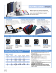
Probes for Coordinate
Measuring Machines
CATALOG No. E4292
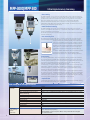
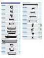
MPP-300Q/MPP-300
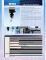
Ultra High-Accuracy Scanning
• Fast scanning
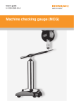
The MPP-300Q/300 is a multi-functional probe designed for CNC coordinate measuring
machines. It can not only perform a continuous path contact-type scanning measurement
[a measurement method that implements a collection of a large amount of coordinate
data while traveling along the path in contact with the workpiece] at V2≤0.3µm (
ireference value when the LEGEX series is installed ), but also high-accuracy point
measurement ( σ ≤0.1µm: when the LEGEX series is installed, and data collection from a
centering point measurement (shown below).
• Omni-directional scanning
The MPP-300Q/300 has internally incorporated high-accuracy scales with a minimum
resolution of 0.01µm for each direction (X, Y, and Z axes), which makes it possible to read
the stylus displacement in any direction.
The air bearing employed in the sliding section of each axis helps enable this probe with
minimum directionality.
• Low measuring force
The ordinary touch trigger probe, even if it has only a small force to generate a trigger
signal the moment the stylus actually comes into contact with the workpiece, may be
subject to several tens to several hundred grams of force at the
press-in that immediately follows contact. In addition, some of
the scanning probes from other manufacturers employ such a
structure that the motor drive mechanism forcibly specifies the
probing position in order to permit the use of a longer stylus,
necessitating the probe to actually have a greater measuring
force.
Centering point In contrast, the MPP-300Q/300 can reduce its measuring force to
a minimum of 0.03N so that it can even measure elastic
measurement
workpieces such as resins, etc., without damaging them at all.
•Fast scanning
For a scanning measurement, either of the following scanning methods can be selected:
one in which scanning progresses while automatically following an unknown geometry
(unknown geometry scanning), or one in which scanning progresses based on the locus of
the probe tip given beforehand (known geometry scanning). With known geometry
scanning it is possible to perform fast scanning at 120 mm/s.
Conventionally, it is normal to evaluate geometries such as a line or a circle through point
measurement. However, for evaluating the flatness or roundness of an extra precisionmachined workpiece, it is better to improve the reliability of the measurement result by
evaluating the object at more measurement points.
Unfortunately, it takes an extended amount of time for a touch-trigger probe to measure
an object point by point. The MPP-300Q/300 can, for example, complete its measurement
in several seconds even if it is required to measure inside diameters of ø100 mm at 1000
measurement points. In addition, measurement can be pursued effectively while changing
the scanning speed, depending on the measurement accuracy required.
• Optional units
A wide variety of optional units, including rotary table MRT320 for synchronized scanning
and the automatic stylus change system, are provided.
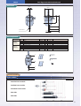
MPP-300Q/MPP-300 Specifications
MPP-300Q/
MPP-300
Automatic
stylus change
system
(optional)
2
Measurement range
Resolution
Max. permissible probing error
Max. permissible probing error
during scanning
Spring rate
Max. stylus length
Max. stylus mass
Stylus mount
Max. tracing speed
Air flow rate
Probe head
Applicable models
No. of mountable stylus modules
±1mm
0.01µm
MPEP≤0.45µm (LEGEX500/700/900: When the ø4X18mm stylus is used.)
MPETHP≤1.4µm (LEGEX500/700/900: When the ø4X18mm stylus is used.)
0.2N/mm
200mm for both vertical and horizontal
75g
M4 screw
120mm/s [at a known geometry scanning]
30NL/min
N/A
CNC CMM (LEGEX500/700/900/1200 series)
- 4 standard units [Port 1 is dedicated for the standard stylus
(for calibration purpose)]
- Expandable to max. 10 ports. Note, all styli should be arranged
on the same axis.
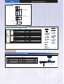
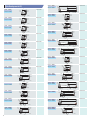
Ultra High-Accuracy Scanning Probe
MPP-300Q/MPP-300
Dimensions
50mm
96mm
ø14mm
CLAMP
147.5mm
X
Y
Z
32mm
MPP-300
50mmm
An example scanning measurement of a ring gage with the LEGEX series and MPP-300
ø46mm
ø88mm
Set configuration
Unit
Ref. No.
1
2
3
4
5
6
7
8
9
10
11
12
13
14
15
16
Configuration
of the MPP-300
main unit No.
02AQD310
MPP-300
probe set
Order No.
06ABJ729
Clamp unit
Description
Part No.
MPP-300 probe main unit
02AQD330
Damping oil
02AQD090
Connection air hose
970117
Storage box
02AQD480
ø4X18mm stylus
–
ø4X50mm stylus
–
Extension L=30 mm
181280
Extension L=50 mm
181281
Extension L=100 mm
06AAD458
MS4-stylus knuckle
06AAD460
MS4-stylus center
06ACH817
Stylus tool
181279
Allen wrench
538411H
Inspection certificate
–
MPP-300 Hardware Guide
99MCA242
MPP-300 clamp unit configuration (of rack-mount specification) 02AQD500A
Qty
1
1
1
1
1
5
2
1
1
1
1
2
1
1
1
1
Mass (kg)
1.5
0.017
0.05
1.5
0.002
0.005
0.005
3.3
0.007
0.01
0.015
0.04
0.001
0.001
0.002
0.15
1.8
Remark
Including one stylus mount assembly.
Silicon oil (2000CS)
Air hose for MPP-CMM
Wooden box for storing MPP-300
Standard stylus
M4-M4 ceramics
M4-M4 ceramics
M4-M4 ceramics
For attaching/detaching M4 stylus
Nominal diameter: 1.5
Hardware-only Operation Manual
* Part number may vary with the main unit configuration.
2
7
50
18
1
CLAMP
5
X
Y
Z
8
ø4 ruby ball
3
6
MPP-300
13
12
50
9
ø4 ruby ball
Insp
30
n Ce
rtific
ate
14
100
Hard
wa
re
10
4
ectio
16
Guid
e
15
11
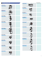
Stylus mount assembly
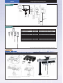
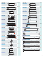
Optional units
Automatic Stylus Changer
Unit : mm
Dimensions
Detail
Measurement range
33
115
600
80
60
80
60
20
80
60
80
Unit
Automatic stylus
change system
Set Order No.
06ABG596
28
Ref. No.
Description
1 Auto-stylus change rack
2 Stylus mount assembly
3 Auxiliary plate
4 ø4X18mm stylus
5 MS4-stylus center
6 Reference sphere
Part No.
06ABG597
02AQD042
06ABG598
—
06ABH817
06ABH818
Qty
1
3
1
3
3
1
Mass (kg)
Remark
5
Supplied with 4 ports for replacement.
Used for installing a rack on the CMM base.
0.04
8
13.04
0.005
0.012
For re-calibration
0.04
Unit : mm
6
New rack
1
2
200
5
5
M4
20
ø50
28
ø50
110
Measurement range
90
3
720
3
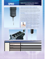
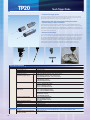
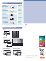
SP80
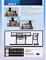
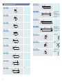
High-accuracy scanning probe adaptive
to long-type stylus
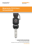
• High-accuracy scanning probe adaptive to long-type stylus
The SP80 scanning probe is designed to employ a long stylus that has high
measurement accuracy and a maximum length of 500 mm (measured in both the
horizontal and vertical directions). It is a multi-function probe for CNC coordinate
measuring machines that undertakes not only scanning measurement (a measurement
method that collects a large amount of coordinate data while traveling along the path
in contact with the workpiece) but also high-accuracy point measurement as well as
data collection from a centering point measurement (shown below).
• Fast scanning
For scanning measurement, either of the following scanning methods can be selected:
one in which scanning progresses while automatically following an unknown
geometry (unknown geometry scanning), or one in which scanning progresses based
on the locus of the probe tip given beforehand (known geometry scanning). With
known geometry scanning it is possible to perform fast scanning at 120 mm/s.
Conventionally, it is normal to evaluate geometries such as a line or circle through
point measurement. However, for evaluating the flatness or roundness of an extra
precision-machined workpiece, it is better to improve the reliability of the
measurement result by evaluating the object at more measurement points.
Unfortunately, extended time is required for a touch-trigger probe to measure an
object point by point. The MPP-300Q/300 can, for example, complete its
measurement in several seconds, even if it is required to
measure inside diameters of ø100 mm at 1000
measurement points. In addition, any measurement can be
pursued effectively while changing the scanning speed,
depending on the measurement accuracy required.
• Optional units
Centering point
measurement
A wide variety of optional units, including rotary table
MRT320 for synchronized scanning and the automatic
stylus change system, are provided.
SP80 Specifications
SP80
4
Measurement range
Max. permissible probing error
during scanning
Spring rate
Max. stylus length
Max. stylus mass
Stylus mount
Max. scanning speed
Probe head
Applicable models
±2.5mm
MPETHP≤2.0µm (Crysta-Apex C700/900: If the ø8X60mm stylus is used.)
1.8N/mm
500mm
500g
M5
120mm/s [at a known geometry scanning]
N/A
CNC coordinate measuring machines
High-accuracy scanning probe adaptive to long-type stylus
SP80
6mm
Dimensions
106mm
150mm
KM80
SH80 main unit
11mm
21mm
41mm
SH80
5 x M5
22mm
Set configuration
SP80 main unit
Description
SP80 basic set
Part No.
06ABT513
Mass (kg)
2.6
Remark
One SP80 main unit, SH80, KM80, and ø8X60mm stylus
KM80
Parts for SP80
Description
SP80 adapter
SP80 Probe cable
SP80 EXT cable
IU 80
SP80 Power Supply BOX
OPT200S-MPP2
OPT200 attachment
Control ROM (MAIN)
Control ROM (OPT)
Part No.
06ABT587
06ABT588
06ABT590
06ABT525
06ABT591
06ABN865
06AAS741
06ZAA058
06ZAA059
Mass (kg)
Mass (kg)
0.3
0.1
0.2
0.51
1
0.2
0.4
0.01
0.01
Qty
1
1
1
1
1
1
1
1
1
3.73
SP80 main unit
SH80
* Part number may vary with the main unit configuration.
Optional units
Automatic Stylus Changer
MRS
SP80 stylus change set 1 (600mm-rail specifications) / Oder No. 06ABT766
Description
MRS kit#2
SH80
SCP80
Rack plate (auxiliary plate)
ACR3 attachment
Part No.
06ABT529
06ABT523
06ABT524
06ABG598
06ABP467
Unit
1
1
2
1
1
Mass (kg)
Mass (kg)
3.5
0.24
2.1
8
0.05
13.89
SP80 stylus change set 2 (1000mm-rail specifications) / Oder No. 06ABT767
SCP80
SCP80
34mm
Description
MRS kit#3
SH80
SCP80
Rack plate (auxiliary plate)
ACR3 attachment
Part No.
06ABT530
06ABT523
06ABT524
06ABG598
06ABP467
Mass (kg)
Unit
1
3
4
1
1
Mass (kg)
3.7
0.48
4.2
8
0.05
16.43
230mm
128mm
5
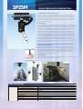
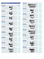
SP25M
Compact High-accuracy Scanning Probe
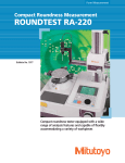
• Compact high-accuracy scanning probes
The SP25 is a compact high-accuracy scanning probe with an outside diameter of ø25
mm. This multi-functional probe is suitable for a CNC coordinate measuring machine that
performs not only scanning measurement (measurement method that collects a large
amount of coordinate data while traveling along the path in contact with the workpiece),
but also high-accuracy point measurement, as well as data collection from a centering
point measurement (shown below).
• Fast scanning
For a scanning measurement either of the following scanning methods can be selected:
one in which the scanning progresses while automatically following an unknown geometry
(unknown geometry scanning), and one in which scanning progresses based on the locus
of the probe tip given beforehand (known geometry scanning). With known geometry
scanning it is possible to perform fast scanning at a maximum of 120 mm/s.
Conventionally, it is normal to evaluate geometries such as a line or a circle through point
measurement. However, for evaluating the flatness or roundness of an extra precisionmachined workpiece, it is better to improve the reliability of a measurement result by
evaluating the object at more measurement points. Unfortunately, an extended of time is
required for a touch-trigger probe to measure such an object point by point. The SP-25
can, for example, complete its measurement in several seconds even if it is required to
measure inside diameters of ø100 mm at 1000 measurement points. In addition, it can
pursue any measurement effectively while changing the scanning speed, depending on the
measurement accuracy required.
• Enhancing the setup and measurement efficiency through automatic
change of probe orientations
Since the SP25 can be mounted on a probe head such as the PH10M/PH10MQ that
automatically changes the probe orientation, it can greatly reduce the preparation time for
measurement and for actual measurement in comparison to a conventional-type scanning
probe whose position is fixed downward. In addition, the use of other probes, as
advantaged by the probe change system, makes it possible to realize full automation in
measuring various forms of machined parts.
• Optional units
Centering point
measurement
A wide variety of optional units, including rotary table MRT320 for synchronized scanning
and the automatic stylus change system, are provided.
SP25M Specifications
SP25M
6
Measurement range
Max. permissible probing error
during scanning
Spring rate
Amount of over travel
Max. stylus length
Stylus mount
Max. scanning speed
Probe head
Applicable models
±0.5mm
MPETHP≤2.3µm (Crysta-Apex C700/900: If the ø4X50mm stylus is used.)
0.4N/mm
±2.0mm (XY) ±1.7mm (Z)
200mm (When SM25-3 or SH25-3 is used.)
M3
120mm/s [at a known geometry scanning]
Essential: PH10M/PH10MQ
CNC coordinate measuring machines
Compact High-accuracy Scanning Probe
SP25M
TP20
module
48.05mm
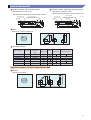
SM25-3
2mm
195.4mm
33.85mm
111.65mm
SM25-2
SH25-1
SH25-2
Stylus that can be attached:
20 to 100mm long
(Overall stylus length between 120 to 200mm.
ø13.25mm
SM25-1
26.25mm
Stylus that can be attached:
20 to 75mm long
(Overall stylus length between 50 to 105mm.)
TM25-20
ø25mm
SP25M
probe body
74.05mm
TM25-20
Stylus that can be attached: 16.95mm
20 to 50mm long
62.5mm
45.55mm
Dimensions
SH25-3
Fixed to
SH25-3.
ø4mm
Fixed to
SH25-3.
Configuration
Description
SP25M full combination kit
Part No.
06ABS969
SP25M scanning kit #1
SP25M scanning kit #2
SP25M scanning kit #3
Scanning module SM25-1 kit
Scanning module SM25-2 kit
Scanning module
Stylus holder SH25-1
Stylus holder SH25-2
Stylus holder SH25-3
TM25-20TTP module adapter kit #1
TTP module adapter kit TM25-20
06ABS970
06ABS971
06ABS972
06ABS452
06ABS453
06ABS454
06ABS455
06ABS456
06ABS457
06ABS475
06ABS473
Remark
A complete set of SP25M, SM25-1/2/3, SH25-1/2/3,
and TM25-20
A complete set of SP25M, SM25-1, and SH25-1
A complete set of SP25M, SM25-2, and SH25-2
A complete set of SP25M, SM25-3, and SH25-3
A complete set of SM25-1 and SH25-1
A complete set of SM25-2 and SH25-2
A complete set of SM25-3 and SH25-3
A set of TP20 standard force module and TM25-20
* TTP module (TM25-20, TP20 module) will be supported for MCOSMOS V2.4 or later releases.
Optional units
Automatic Scanning Module Changer/Automatic Stylus Changer
* SP25M internally uses the high-power LED light source. Exercise caution when
handing, in accordance with the Operation Manual.
* Can be mounted on the MRS rack.
7
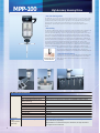
MPP-100
High-Accuracy Scanning Probe
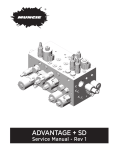
• Low-cost scanning probes
The MPP-100 is a low-price and high-accuracy scanning probe. It is a multi-function probe
for CNC coordinate measuring machines that performs not only a scanning measurement
(a measurement method that collects a large amount of coordinate data while traveling
along the path in contact with the workpiece) but also a high-accuracy point
measurement, as well as data collection from centering point measurement (shown
below).
• Fast scanning
For scanning measurement, either of the following scanning methods can be selected: one
in which scanning progresses while automatically following an unknown geometry
(unknown geometry scanning), and one in which scanning progresses based on the locus
of the probe tip given beforehand (known geometry scanning). With known geometry
scanning it is possible to perform fast scanning at 120 mm/s. Conventionally, it is normal
to evaluate geometries such as a line or circle through point measurement. However, for
evaluating the flatness or roundness of an extra precision-machined workpiece, it is better
to improve the reliability of a measurement result by evaluating the object at more
measurement points. Unfortunately, an extended amount of time is required for a touchtrigger probe to measure such the object point by point. The MPP-100 can, for example,
complete its measurement in several seconds, even if it is required to measure inside
diameters of ø100 mm at 1000 measurement points. In addition, it
can pursue any measurement effectively while changing the
scanning speed, depending on the measurement accuracy required.
• Omni-directional scanning
Centering point
measurement
The MPP-100 has internally incorporated high-accuracy scales with
a minimum resolution of 0.01µm for each direction (X, Y and Z
axes), which makes it possible to read the stylus displacement in
any direction.
MPP-100 Specifications
MPP-100
Automatic
stylus
change system
(optional)
8
Measurement range
Resolution
Max. permissible probing error
during scanning
Spring rate
Max. stylus length
Max. stylus mass
Stylus mount
Max. scanning speed
Air flow rate
Probe head
Applicable models
No. of mountable stylus modules
±1mm
0.1µm
MPETHP≤3.0µm (Crysta-Apex C series: if the ø4x18mm stylus is used.)
0.75N/mm
200mm for both vertical and horizontal
75g
M4 screw
120mm/s
30NL/min
N/A
CNC CMM (Crysta-Apex C series, Bright-STRATO series)
- 4 standard units [Port 1 is dedicated to the standard stylus
(for calibration purposes)]
- Expandable to a maximum 10 ports. However, all styli should be
arranged on the same axis.
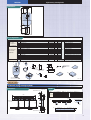
High-Accuracy Scanning Probe
MPP-100
ø90mm
ø14mm
50mm
Dimensions
CLAMP
141.5mm
X
Y
Z
50mm
32mm
MPP-100
ø46mm
ø92mm
Set configuration
Unit
MPP-100
main unit
configuration
No. 02AQD010
MPP-100 probe
set Order No.
06ABG594
Clamp unit
Ref. No.
1
2
3
4
5
6
7
8
9
10
11
12
13
14
15
16
Description
Part No.
02AQD030
MPP-100 probe main unit
02AQD090
Damping oil
970117
Connection air hose
02AQD020
Storage box
–
ø4X18mm stylus
–
ø4X50mm stylus
181280
Extension L=30mm
181281
Extension L=50mm
06AAD458
Extension L=100mm
06AAD460
MS4-stylus knuckle
06ABH817
MS4-stylus center
181279
Stylus tool
538411H
Allen wrench
–
Inspection certificate
99MCA231
MPP-100 Hardware Guide
MPP-100 clamp unit configuration (desktop specification) 02AQD100A
Qty
1
1
1
1
1
5
2
1
1
1
1
2
1
1
1
1
Mass (kg)
1.5
0.017
0.05
1.5
0.002
0.005
0.005
3.3
0.007
0.01
0.015
0.04
0.001
0.001
0.002
0.15
1.8
Remark
Including one stylus mount assembly.
Silicon oil (2000CS)
Air hose for MPP-CMM
Wooden box for storing MPP-100
Standard stylus
M4-M4 ceramics
M4-M4 ceramics
M4-M4 ceramics
For attaching/detaching M4 stylus
Nominal diameter: 1.5
Hardware-only Operation Manual
* Part numbers may vary with the main unit configuration.
2
7
50
18
1
8
CLAMP
X
Y
Z
5
3
ø4 ruby ball
6
MPP-100
ø4 ruby ball
9
Insp
30
13
12
50
ectio
n Ce
rtific
ate
14
100
Hard
wa
re
4
16
Guid
e
10
15
11
Stylus mount assembly
Unit : mm
Optional units
Automatic stylus change system
Dimensions
Unit : mm
Measurement range
33
115
600
80
60
80
60
20
80
60
80
Detail
Unit
Ref. No.
Description
Automatic
1 Auto-stylus change rack
stylus change
2 Stylus mount assembly
system
3 Auxiliary plate
Set No. 06ABG596 4 ø4X18mm stylus
5 MS4-stylus center
6 Reference sphere
Part No.
06ABG597
02AQD042
06ABG598
916491
06ABH817
06ABH818
Qty
1
3
1
3
3
1
Mass (kg)
Remark
5
Supplied with 4 ports for replacement.
0.04
8
Used for installing a rack on the CMM base.
13.04
0.005
0.012
0.04
For re-calibration
28
Unit : mm
6
1
New rack
2
5
200
5
M4
20
Ø50
28
Ø50
3
110
Measurement range
90
720
9
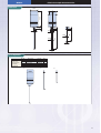
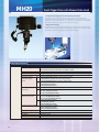
MPP-10
Effective Screw Depth Measurement Probe
• Special unique model for measuring effective screw depth
Screw holes, or female screws, may not function well on fastening if the depth is
insufficient, or extended machining time may be required, or the strength of the target
workpiece may be affected if the depth is excessive. Therefore, it is very important to
ensure that each hole is of an appropriate effective depth. Today’s general method of
measuring the effective depth of a female screw is for the operator to manually drive-in a
dedicated tool called a “screw gage” in the target hole to identify the depth. However,
since some automobile engine parts have more than 100 female screws, screw gage can
consume a significant amount of time, contributing to excessive overhead. The MPP-10 is
only one probe model that has enabled automatic measurement of female screw depths
using a CNC coordinate measuring machine.
• Enhancing the setup and measurement efficiency through the automatic
change of probe orientations
Since the MPP-10 can be mounted on a probe head, such as the PH10M/PH10MQ, that
automatically changes the probe orientation, it is capable of automatically measuring
workpieces in which many female screws have been machined in various directions. In
addition, the use of other probes, as advantaged by the probe change system, makes it
possible to realize full automation in measuring various forms of machined parts.
Imperfect threads
Preamp
Screw
bottom
side
Strain
gage
Stylus
Tracing
direction
MPP-10 Specifications
Female screws that can be measured
Maximum measurement depth
M4-M8 screw
M4-M20 screw
Maximum measuring speed
M4-M10 screw
M12-M20 screw
Probe outside diameter
10
M4 - M20
30mm
60mm
10mm/sec
30mm/sec
ø25mm
Perfect threads
Screw
surface
side
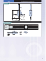
Effective Screw Depth Measurement Probe
MPP-10
Dimensions
Unit : mm
6
1.5
1.5
7.5
55.5
ø25
10
65
ø0.8
40
ø0.6
2
3
Set configuration
MPP-10
main unit
configuration
Order No.
02AQD210
Ref. No.
1
2
3
4
5
1
Description
MPP-10 main unit
Stylus (L65x3)
Stylus (L40x2)
Stylus mounting tool
Storage box
Qty.
Part No.
02AQD220
1
02AQD250
1
02AQD260
1
02AQD211
1
02AQD270
1
2
3
11
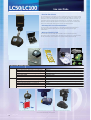
LC50/LC100
Line Laser Probe
• Ultra-fast data collection
The LC50/100 probe is designed to collect coordinate values on the workpiece surface
while it is irradiating the workpiece with a line-formed laser beam as it travels over the
workpiece. Since it can collect data at the ultra high speed of 19,200 points/sec., the
LC50/100 is able to complete a form measurement of, for example, an automobile
body part, which would take several hours to several tens of hours to measure even
with a non-contact type scanning probe, within only several minutes.
• Advantages due non-contact measurement
Since this probe is a non-contact type, it can measure even elastic bodies such as
resins and thin machined parts that can be easily deformed by contact-type
measurement.
• Wide uses included for CAD
The collected set of point data can be utilized for various purposes by editing,
generating a plane, comparison with CAD data, and conversion into CAD data, which
can be performed by the rich selection of optional software titles supported.
LC50/LC100 Specifications
LC50
LC100
Accuracy
Working distance (Dimension a in Figure 1)
Measurement range (Dimension b in Figure 1)
Laser width (Dimension c in Figure 1)
Data input speed
Laser standard
Accuracy
Working distance (Dimension a in Figure 1)
Measurement range (Dimension b in Figure 1)
Laser width (Dimension c in Figure 1)
Data input speed
Laser standard
≤15µm
100mm
50mm (50mm in positive direction from working distance)
50mm
19200point/sec
Class II
≤20µm
100mm
100mm (100mm in positive direction from working distance)
50mm
19200point/sec
Class II
a
b
c
Figure 1: Measurable area with LC50/100
12
* The high-accuracy model, LC15, and the XC50 model, which allows faster data collection
due to the three-line laser beam, are also provided.
Line Laser Probe
LC50/LC100
105mm
60mm
55mm
Dimensions
95mm
Set Configuration
No. Group
1
2
3
4
5
Metris LC-100
6
A
Probe Set
7
[60ABP442]
8
9
10
11
12
1
2
3
4
5
Metris LC-50
6
B
Probe Set
7
[06ABP500]
8
9
10
11
12
1
PICS JCBOX
2
C
Set
3
[06ABP472]
4
Description
Part No.
Metris probe (LC-100) 06ABP443
06ABP445
Master ball
06ABP446
Calibration Disk
06ABP447
Case
06ABP448
MPI add-in card
06ABP449
Frame grubber add-in card
06ABP450
Encoder add-in card
06ABP451
MPI-ENC cable
06ABP452
Control cable
06ABP453
Video cable
06ABP474
Metris PICS cable
06ABL115B
Multiwire Extension Harness
Metris probe (LC-50) 06ABP444
Metris LC-50
Master ball
06ABP445
Probe
Calibration Disk
06ABP446
[06ABP499]
Case
06ABP447
MPI add-in card
06ABP448
Frame grubber add-in card
06ABP449
Encoder add-in card
06ABP450
MPI-ENC cable
06ABP451
Control cable
06ABP452
Video cable
06ABP453
Metris PICS cable
06ABP474
Multiwire Extension Harness
06ABL115B
PICS JCBox
06ABN603
PICS cable
06AAJ456B
PICS cable
916624
USB cable
06ABP473
Metris LC-100
Probe
[06ABP455]
Qty
1
1
1
1
1
1
1
1
1
1
1
1
1
1
1
1
1
1
1
1
1
1
1
1
1
1
1
1
Mass (g)
Remark
300
LC-100 probe
750
30
200
200
400
700
20
Flat cable
250
15-15-9 pin connector cable
100
Coxial-15 pin cable
100
400
15-15pin Cable
300
LC-50 probe
750
30
200
200
400
700
20
Flat cable
250
15-15-9 pin connector cable
100
Coaxial-15 pin cable
100
400
15-15pin Cable
800
300
5m
200
1.5m
350
5m
B
A
1
3
1
3
2
2
4
4
5
7
8
6
5
7
8
6
10
10
9
12
11
9
11
12
C
1
4
2
3
Optional software
Surface
Generates a plane from pointclouds, which are randomly
corrected by the laser probe, etc.
CADCompare
Compares the measurement data and existing CAD data.
13
WIZprobe
Point Laser Probe
• High-accuracy laser probe
The WIZprobe affords two kinds of measurement: one in which point measurement
using single-point measurement is performed by the point laser, with a spot diameter
of 30µm, is irradiated into a workpiece, and the other in which scanning
measurement is performed by collecting a workpiece profile as point-group data.
• Automatic form tracing
If the probe makes a scanning measurement along the profile of an unknown
geometry, it continues measurement while automatically following the geometry. In
this case, measurement can be commenced by simply supplying the start position,
measuring direction, and finish position.
• Enhancing the setup and measurement efficiency through the
automatic change of probe orientations
Since WIZprobe can be mounted on a probe head, such as the PH10M/PH10MQ, that
automatically changes the probe orientation, it can be used for full-automated
measurement on a surface including the top and bottom of, for example, the cross
section of a turbine blade that is typically found in aircraft engines.
WIZprobe Specifications
WIZprobe
14
Working distance
Measurement range
Point-by-point measurement repeatability
Data input speed
Laser spot diameter
Laser standard
Applicable data processing unit
50mm
±5mm (±5mm from the working distance)
≤6µm
50point/sec
30µm
Class II
MCOSMOS
Point Laser Probe
WIZProbe
Dimensions
ø25mm
93mm
55mm
102mm
30mm
Set Configuration
No. Group
1
2
3
4
5
6
7
8
9
10
1
2
3
4
A
B
Description
WIZprobe SET1 WIZprobe Sensor
(include case)
Calibration
Sphere Rod
[06ABP461]
User Interface Box
WIZcard Extension Cable
WizProbe Set
12Volts cable
[06ABP342]
WIZcard PC add-in card
Software CD-ROM
WIZprobe-Acceptance test report
SY-TR
I/F BOX Set
[06ABP424]
Part No. Qty Mass (g)
06ABP332 1
1600
06ABP336 1
06ABP334
06ABP335
06ABP338
06ABP333
06ABP339
06ABP346
1
1
1
1
1
1
200
200
20
200
100
10
WIZpobe Cable
06ABP343
1
500
PC Serial Communication Cable
SYTR-I/F Box
PICS cable
User cable
RS232C cable
06ABP344
06ABH630
916624
06ABH627
06ABN299
1
1
1
1
1
100
400
200
300
300
A
Remark
PK-07-PR-00-000-0
PK-05-ME-00-200-0
4
1
B
2
1
2
PK-70-IB-00-400-0
PK-05-00-CB-062-0
3
PK-07-WC-00-000-0
Includes manual
3
4
Renishaw multi-wire standard A-1016-7617
PH-10 Autojoint cable
PK-05-00-00-031-0
5
1.5m
6
s-s cross cable (9pin)
7
8
9
10
15
QVP
Quick Vision Probe
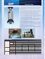
• Provides image measuring capability for coordinate measuring machines
The QVP probe performs form measurement by image processing micro geometry that
cannot be measured by a contact type probe, or elastic bodies that are easily deformed by
slight measuring forces.
Although the method of microscopic measurement with the centering microscope
mounted on the coordinate measuring machine has been used since coordinate measuring
machines came into use in the industry, they have an inherent disadvantage in that the
operation of identifying positions is dependent on the operator’s eye, resulting in possible
measurement errors. Even with a CNC coordinate measuring machine manual
measurement must be performed sometimes, such as with an installed centering
microscope. The QVP probe is an vision probe dedicated for coordinate measuring
machines and was developed based on Mitutoyo’s state-of-the-art technology, in order to
enable full automation of image measurement with a CNC coordinate measuring machine.
This technology was originally developed for Mitutoyo vision measuring machines.
• Automatic detection of workpiece edge
The QVP-captured image will have various automatic edge detections performed by the
dedicated software, Visionpak, and then various calculation processes (calculation of
dimensions and geometrical deviations) will be performed by the general-purpose
measurement program, Geopak.
• Standard provision of white LED illumination
Since the QVP is equipped with the standard co-axial light running through the lens system
as well as white-light LED ring illumination, which is bright and has a long service life, no
auxiliary illumination is required. The light volume can be set to between 0 and 100% at
1% increments.
• Mounting onto the Automatic Probe Changer
The QVP can also be mounted onto an automatic probe changer, allowing full-automatic
measurement including both the contact and non-contact types in combination with the
contact-type probes.
QVP Specifications
QVP main unit
Objective
QVP I/F BOX
16
CCD size
Optical tube magnification
Illuminating Co-axial
Ring
function
Mass
Optical magnification
Observation range (mm)
Working distance (mm)
Magnification
Numerical Aperture (N.A.)
Depth of focus (µm)
Mass
Supply voltage
Frequency
Power capacity
Mass
1/2 inch (B/W)
0.5X
White light LED source (built-in): Power dissipation 5W or less
White light LED source: Power dissipation 10W or less
Automatic-joint type: 310g, shank type: 385g
0.5X
1.5X
2.5X
5X
9.6X12.8
3.2X4.3
1.9X2.6
1X1.3
59
72.3
59.5
44
1X
3X
5X
10X
Optional
Standard
Optional
Optional
0.03
0.07
0.11
0.18
306
56
23
8
70g
47g
59g
75g
AC100 to 240V
50/60Hz
45W
3800g
Quick Vision Probe
QVP
Dimensions
Optional accessories
Objective ML1X (375-036)
Objective ML5X (375-034)
Objective ML10X (375-035)
ø 70
ø 70
66
26
50
ø 25
66
ø13.99
40
32
26
40
W.D.= 72.3
211.7
182.7
37.7
113
Calibration gage
(02AQC310)
- Gage for sharing the
coordinates between the QVP
and contact-type probe
QVP-A
(Automatic-joint type)
Calibration chart
(958448)
- Gage for calibrating
a single QVP unit
QVP-S
(Shank type)
Unit : mm
Data processing unit
Dedicated data processing software VISIONPAK
VISIONPAK operates under the Microsoft Windows operating system
and is a general-purpose measurement program for coordinate
measuring machines. It displays the image window when it detects a
workpiece edge. After detecting an edge, it undertakes various
calculations with the regular general-purpose measurement programs.
Wide variety of image processing functions
With the powerful image processing functions (tools) it can detect
various forms of edges at high speed. It can measure in the height
direction by means of its auto-focus function, and save the captured
image as the image data (bitmap format) as well.
Outlier removal function
In ordinary micro-form measurement it is often difficult to remove burrs
and dusts from the objective workpiece, resulting in an inevitable
measurement error. In contrast, VISIONPAK can recognize, for example,
the obstruction as an "outlier" and bypass it during measurement.
VISIONPAK Image Processing Tool
Simple tool
Used for detecting a single point
on the edge pointed to by the
arrow.
Box tool
Used for multiple-point line
measurement of an edge caught
in the box
Circle tool
Used for multiple-point measurement
of a circle for the objective circular
edge. As with the box tool, it can
collect data that is free from the effect
of burrs and dust.
Manual tool
Used for detecting an optional
position pointed to (clicked on)
by the mouse.
Centroid tool
Used for detecting the center of
gravity of an optional form.
Edge self-tracing tool
By simply specifying the start
point and measurement interval,
the objective edge can be
detected while automatically
tracing an unknown geometry.
17
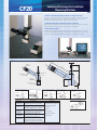
Centering Microscope for Coordinate
Measuring Machines
CF20
• Use the coordinate measuring machine as a large microscope
The CF20 is a centering microscope that enables measurement of small holes and elastic
bodies which are difficult for a touch trigger probe to measure. With the CF20 the
coordinate measuring machine can be used as a large microscope.
• Optional accessories to implement various evaluations
To cope with the size and form of a workpiece to be observed and measured, lenses of
various magnifications and reticles for form comparison are provided.
• CCTV monitor system
The dedicated CCD camera can be mounted on the back of the CF20 main unit. Video
signals from the camera can be displayed as an image on the external monitor. This is a
great aid in relieving eye stress, especially if several hours of work must be done.
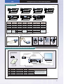
CF20 monocular set dimensions
ø14mm
21
50mm
Eyepiece
1m
m
CF20 main unit
30˚
117mm
Monocular unit
51mm
Objective
(optional)
22.5mm
Illumination unit
CF20 monocular set (375-201)
CF20 binocular set (375-202)
Shank (ø14mm)
Shank (ø14mm)
Binocular unit
Monocular unit
CF20 protractor eyepiece set
(375-203)
Shank (ø14mm)
CF20 disc plate set (375-205)
Shank (ø14mm)
Disc-plate eyepiece unit
Double-image eyepiece unit
Protractor eyepiece unit
Main unit
Main unit
CF20 double image set
(375-204)
Shank (ø14mm)
Main unit
Main unit
Main unit
Specifications
Description
Specification
CF20 monocular CF10X eyepiece, field number 22
set (375-201)
Cross hair and concentric circle reticle
CF20 binocular
set (375-202)
CF20 protractor
eyepiece set
(375-203)
CF20 double
image set
(375-204)
CF20 disc plate
set (375-205)
18
Accessory
1. Illumination unit (375-071)
2. Spare lamp (162151)
CF10X eyepiece, field number 22
Cross hair and concentric circle reticle (right)
3. Lens cap
Pupil distance adjustment: 51 - 76mm
4. Tools
CF10X eyepiece, field number 21
Measurement range: 360˚, Angle index: 1˚ 5. Power cable
Minimum reading: 5' (vernier scale)
6. Operation Manual
CF10X eyepiece, field number 22
7. Storage box
CF10X eyepiece, field number 22
ISO metric/unify screws
Cross hair and concentric circle reticle/
dotted line cross scale, ML 3X objective
Illumination unit (375-071)
Lamphouse
Power
supply box
Centering Microscope for Coordinate Measuring Machines
CF20
Objectives (optional)
Description
66
8
44
(working distance)
60
110
(parfocal distance)
Numerical
Working distance
Aperture (N.A.)
W.D. (mm)
50
(working distance)
110
(parfocal distance)
11.5
Resolution
R (µm)
Depth of focus of single
objective lens ±D.F. (µm)
Mass
(g)
CF 1X
0.03
73.7
9.2
306
45
375-032
CF 2X
0.06
92
4.6
76
35
375-033
CF 3X
0.07
77.8
3.9
56
35
375-037
ML 3X
0.07
72.5
3.9
56
45
375-034
ML 5X
0.11
59.5
2.5
23
80
375-035
ML 10X
0.18
44.0
1.5
8
100
6.9
171
2.75
27
2.75
27
CF zoom
1X - 5X
1X
0.04
3X
0.1
5X
0.1
72.5
(working distance)
110
(parfocal distance)
5
375-031
375-038
ø25
ø30
37.5
50
ø37.2
ø34
ø28
ø25
ø30
59.5
(working distance)
110
(parfocal distance)
ø25
ø30
5
77.8
(working distance)
110
(parfocal distance)
CF zoom 1X - 5X
ø21.2
ø28
ø25
ø17
ø30
32.2
ML 10X
50.5
Order No.
92
(working distance)
110
(parfocal distance)
ø25
12
ML 5X
10.5
ø25
18
Unit: mm
ML 3X
ø21.5
36.3
5
73.7
(working distance)
110
(parfocal distance)
CF 3X
ø22
ø30
ø25
CF 2X
ø26
ø30
CF 1X
200
Values for resolution and depth of focus of a single objective lens are calculated based on the reference wavelength (∆=0.55µm).
The real field of view (mm) can be obtained from Field number/Objective magnification.
Fiber optic circular illumination unit
(176-366)
Twin-fiber optic illumination unit
(176-344)
Unit: mm
0.2
1
10
1
0.2
ø18
60º
(cross hair and
concentric circle)
(90º/60º dash-dot line)
No. 375-021
No. 375-022
No. 375-023
10
(grid)
No. 375-024
CCTV Monitor System for CMM with CF20 [Order No. 320-053]
5. C-mount adapter (C)
Monitor cable (supplied with
the color monitor of 3,
below)
1. 1/2-inch, 410,000-pixel
color camera
4. Camera cable,
length: 3m
3. Color monitor,
2. Controller
15-inches
- Vertical reference line: Move, lock
(2 for each vertical and horizontal line)
- Video output: VGA, NTSC (VBS), Y/C synchronous outputs
6. Operation
Manual
CCTV (VGA) system
Description
Qty
1
06AAV876
1/2-inch color camera
1
2
06AAV875
Controller
1
3
06AAV877
Color monitor unit
1
Manufactured by SONY
4
06AAV878
Camera cable
1
Length: 3m
5
972031
C-mount adapter (C)
1
User's Manual
1
Ref. No.
6
Part No.
Remark
CCD
Color TV (VGA) System No. 06AAV874,
which includes the accessory set of
Ref. Nos. 1 to 4 (common to the order
No. 176-372 CCD Color TV System)
Common to 176-372
Real field of view (mm) on the monitor can be obtained from CCD camera's imaging device pixels (VxH)/Objective magnification.
19
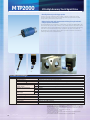
MTP2000
Ultra High-Accuracy Touch Signal Probe
• Ultra high-accuracy touch trigger probes
Provides a very high repeatability (2σ ≤ 0.15µm). In addition, the Mitutoyo original
structure guarantees high-accuracy roundness and sphericity measurements as aided
through probing with minimum directionality.
• Enhancing the setup and measurement efficiency through automatic
change of probe orientations
Since the MTP2000 can be mounted on a probe head, such as the PH10M/PH10MQ, that
automatically changes the probe orientation, it can greatly reduce the preparation time for
measurement and for actual measurement in comparison to a conventional-type scanning
probe which has a downward fixed position. In addition, the use of other probes, as
advantaged by the probe change system, makes it possible to realize full automation in
measuring various forms of machined parts.
MTP2000 Specifications
MTP2000
Measuring direction
Standard stylus
Repeatability (2 )
Directionality (XYZ: 3D)
Required force to generate
trigger signal
Amount of over-travel
Required force to achieve
over-travel
Max. stylus length
Stylus mounting method
Mass of a single unit
Durability
Probe head
Applicable models
XY
Z
XY
Z
XY
Z
±X, ±Y, +Z
ø4X20mm high-accuracy specifications
0.15µm or less (ø4X18mm stylus, at a measuring speed of 3mm/s)
±0.5µm or less (ø4X18mm stylus, at a measuring speed of 3mm/s)
0.006N (When the ø4X20mm stylus is used.)
0.1N (When the ø4X20mm stylus is used.)
±5 to 6°
+1.5mm
1.15N
2.94N
100mm in the vertical direction, and 51mm in the horizontal direction
M4 screw
95g
1,000,000 times
Essential: PH10M/PH10MQ
CNC coordinate measuring machines (LEGEX series)
Notes:
20
• Where the 5-directions stylus knuckle is attached, it is not possible to insert an intermediate extension.
• Where the 5-directions stylus knuckle is attached, it is possibe to insert an extension of up to 500mm.
• Where more than one styli are mounted, the sum of the moments of all styli should be 10N m or less.
Moment of each stylus (N m) = M(g) X (L+20) X 9.8/1000
Where M(g) is the stylus mass, and L(mm) is the distance from the stylus' momentplane of the stylus
holder to the center of the stylus.
• Any ball stylus with its diameter less than ø1mm cannot be used.
• Use a measuring speed of 3mm/s or more.
• Input error may result, if the environment includes radio frequency source greater than 5Hz or
noise source greater than 70dB.
• Soft workpieces or those which are soiled with oils, etc., may not be measured.
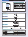
Ultra High-Accuracy Touch Signal Probe
MTP2000
Dimensions
Set configuration [Order No. 06ABK839]
ø35mm
ø25mm
No.
1
Description
Part No.
MTP2000 main unit
configuration
1-1
MTP2000 main unit
1-2
Stylus mounting fixture
Storage box
1-3
MS4-stylus tool
High-accuracy stylus
ø4X18mm
2
MTP2000 I/F BOX
configuration
2-1
MTP2000 I/F BOX
2-2
Probe ID cable
3
Hardware Guide
Remark
1
Set No.
02AQC670
02AQC660 02AQC661
02AQC940
181279
1
1
1
1
06ABK810
1
02AQC700B
1
02AQC710
02AQC800
99MCA173J
1
1
1
ForFor
attaching/
attaching/
detaching M4 stylus
18mm
2.3mm
81.3mm
1-4
Qty
06ABK840
Option accessories
High-accuracy styli
Unit : mm
Order No. : 06ABT109
Description : MS4-1R4.5-S
Stainless
steel
ø7
ø0.7
M4X0.7
ø1 ruby ball
Sphericity: 0.08µm or less
4.5
19.5
Mass: 2.5g
Stainless
steel
M4X0.7
ø2 ruby ball
Sphericity: 0.08µm or less
ø7
ø1.35
Order No. : 06ABK815
Description : MS4-2R8-S
8
19
Order No. : 06ABK816
Description : MS4-4R13.5-S
Mass: 2.3g
Stainless
steel
ø4 ruby ball
Sphericity: 0.08µm or less
ø7
ø3
M4X0.7
13.5
18
Mass: 2.1g
Ceramics
M4X0.7
ø4 ruby ball
Sphericity: 0.08µm or less
ø7
ø3
Order No. : 06ABT110
Description : MS4-4R33C-S
33
50
Ceramics
M4X0.7
ø8 ruby ball
Sphericity: 0.08µm or less
ø7
ø4.5
Order No. : 06ABT111
Description : MS4-8R50C-S
Mass: 4.8g
50
Ceramics
ø8 ruby ball
Sphericity: 0.08µm or less
ø4.5
M4X0.7
ø7
Order No. : 06ABT112
Description : MS4-8R100C-S
Mass: 5.1g
100
Mass: 6.6g
High-accuracy stylus set [Order No. 06ABT114]
Description
Mass (g) Qty
Remark
MS4-1R4.5-S
2.5
2
MS4-2R8-S
2.3
2
MS4-4R13.5-S
2.1
2 High-accuracy stylus
MS4-4R33-S
4.8
1 (Sphericity: 0.08µm or less)
MS4-8R50C-S
5.1
1
MS4-8R100C-S
6.6
1
MS3-30C
18
1 ø30mm ceramic
MS4-EXT50C
6.7
2 50mm ceramic extension (M4)
MS4-EXT30C
5.1
1 30mm ceramic extension (M4)
MS4-M3EXT20
3.2
1 20mm extension (M4 male - M3 female)
Description
MS4-M3EXT75C
MS4-stylus center
MS3-stylus center
MS2-stylus center
MS4-stylus tool
MS2-stylus tool
MS4-M3 femal-adapter
MS3-M2 femal-adapter
Storage box
Mass (g) Qty
Remark
5.2
1 20mm extension
(M4 male - M3 female)
12.1
1
2.4
1
0.8
1
3.5
2
0.7
2
1.4
2 M4 male - M3 female
0.6
5 M3 male - M2 female
700
1
21
TP7M
( high-accuracy )
High-Accuracy Touch Trigger Probe
• High-accuracy touch trigger probes
This is a high-accuracy touch trigger probe with a maximum repeatability of 2σ≤0.25µm.
• Enhancing the setup and measurement efficiency through automatic
change of probe orientations
Since the TP7M can be mounted on a probe head, such as the PH10M/PH10MQ that
automatically changes the probe orientation, it can greatly reduce the preparation time for
measurement and for actual measurement in comparison to a conventional-type scanning
probe with a position that is fixed downward. In addition, the use of other probes, as
advantaged by the probe change system, makes it possible to realize full automation in
measuring various forms of machined parts.
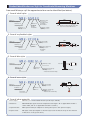
• Adaptive to long-type stylus
The TP7M can mount a long stylus up to 180 mm long*. In combination with the longest
extension of 200 mm equipped for the PH10M/PH10MQ, it can reach a position at a
maximum distance of 380 mm.
* This maximum length may vary with the coordinate measuring machine main unit being
used and/or the material/diameter of the stylus itself.
TP7M Specifications
TP7M
Measuring direction
Standard stylus
Repeatability (2 )
Directionality (XY: 2D)
Required force to generate
trigger signal
Amount of over-travel
Required force to achieve
over-travel
Maximum stylus length
Stylus mounting method
Mass of a single unit
Durability
Probe head
Applicable models
22
XY
Z
XY
Z
XY
Z
±X, ±Y, +Z
ø4X18mm
0.25µm or less (When the standard stylus is used.)
±0.25µm or less
0.02N (When the 50mm stylus is used.)
0.15N (When the 50mm stylus is used.)
±16º
±5mm
0.49N (When the 50mm stylus is used.)
2.94N (When the 50mm stylus is used.)
150mm
M4 screw
85g
10,000,000 times
Essential: PH10M/PH10MQ
CNC coordinate measuring machines
High-Accuracy Touch Trigger Probe
TP7M ( high-accuracy )
Dimensions
ø25mm
18mm
3mm
50mm
RENISHAW
ø4mm
Set configuration [Order No. 916483]
Unit : mm
M4-stylus mount
TP7M probe
stylus set
No. 916484
Ref.
Description
No.
1 Touch trigger probe TP7M
Part No. Mass(g) Qty
916486
85
1
Remark
1
Automatic joint
15
ø25
Unit
2 Joint key S10
174748
24
1
3 M4-stylus tool
181279
3.5
2
For attaching/detaching
4 M2-stylus tool
153140
0.7
2
the stylus
5 Stylus ø8X100 (M4)
916488
6.8
1
6 Stylus ø8X50 (M4)
916487
5.3
1
7 Stylus ø4X18 (M4)
916491
2.2
1
8 Stylus ø2X19 (M4)
916490
2.2
4
3
9 Stylus ø1X19.5 (M4)
916489
2.5
1
4
10 Stylus ø30 ceramic (M3)
916492
15.3
1
11 Stylus ø5X21 (M3)
163873
1.5
1
12 Stylus ø0.5X20 (M3)
163871
1.0
2
13 Stylus ø6X10 (M2)
160219
0.9
1
14 Stylus ø3X10 (M2)
153136
0.4
5
15 Extension L100
181285
6.3
1
50
16
17
18
2
19
Standard stylus
5
20
21
22
6
23
7
M4 male - M3 female
16 Extension L75
181284
5.3
1
M4 male - M3 female
17 Extension L50
181283
4.6
1
M4 male - M3 female
18 Extension L20
181282
3.2
1
M4 male - M3 female
19 Extension L50
181281
6.8
1
M4
20 Extension L30
181280
5.1
1
M4
21 Extension L30
160229
1.4
1
M2
22 Extension L20
160228
0.9
1
M2
23 Extension L10
160227
0.4
1
M2
24 Adapter L9
181286
1.3
2
M4 male - M3 female
25 Adapter L5
160231
0.6
5
M4 male - M3 female
26 MS4-stylus center
916493
12
1
M4
27 MS3-stylus center
168677
3.3
1
M3
28 MS2-stylus center
160230
1.0
1
M2
29 Wooden box
916494
700
1
30 Probe extension PEM1
916495
65
1
L50
Extension
set
31 Probe extension PEM2
916496
90
1
L100
No. 916485
32 Probe extension PEM3
916497
150
1
L200
33 Wooden box
916498
600
1
34 User's Manual
916499
100
1
24
8
25
9
26
27
10
28
29
11
ø25
12
30
ø25
13
31
14
32
ø25
33
23
TP200
High-Accuracy Touch Trigger Probe
• Compact high-accuracy touch trigger probes
This touch trigger probe has an outside diameter as small as ø13.5 mm, which greatly
contributes to probing complex portions of a workpiece. With the combined use of an
appropriate probe extension it can probe even deeper locations.
• Enhancing the setup and measurement efficiency through the
automatic change of probe orientations
Since the TP200 can be mounted on a probe head, such as the PH10M/PH10MQ that
automatically changes the probe orientation, it can drastically reduce the time required to
prepare for measurement and for actual measurement in comparison to a conventionaltype scanning probe with a position that is fixed downward.
• Automatic stylus change
If the measurement cannot be performed by merely changing the probe orientation (such
as when it is impossible to measure without replacing the normal stylus with one that has
a different diameter or unique form), this automatic stylus change via the stylus change
system allows full-automatic measurement to be completed without being interrupted
mid-course. In addition, working with other probes, as advantaged by the probe change
system, makes it possible to realize full automation in measuring various forms of
machined parts.
TP200 specifications
TP200
Measuring direction
Repeatability (2 )
Directionality (XY: 2D)
Directionality (XYZ: 3D)
Required force to generate
trigger signal
Amount of over-travel
Required force to achieve
over-travel
XY
Z
XY
Z
XY
Z
Maximum stylus length
SCR200
(optional)
24
Maximum stylus mass
Stylus mounting method
Mass of a single unit
Durability
Probe head
Applicable models
Note:
Stylus module replacement
accuracy
Number of stylus modules that
can be mounted
±X, ±Y, ±Z
0.3µm or less (with 10mm stylus), 0.4µm or less (with the 50mm stylus)
±0.4µm or less (with 10mm stylus), ±0.8µm or less (with the 50mm stylus)
±0.65µm or less (with 10mm stylus), ±1µm or less (with the 50mm stylus)
0.02N (STANDARD/LOW FORCE), where a 50mm stylus is used.
0.07N (STANDARD/LOW FORCE), where a 50mm stylus is used.
XY±14º
+4.5mm (with 0.07N), +3mm (with 0.15N)
0.35N (STANDARD FORCE)
0.1N (LOW FORCE)
4N (STANDARD FORCE)
1N (LOW FORCE)
50mm (STANDARD FORCE)
30mm (LOW FORCE)
8g (STANDARD FORCE), 3g (LOW FORCE)
M2 screw
22g
10,000,000 times
Essential: PH10M/PH10MQ/MIH/PH1
CNC coordinate measuring machines
Any stylus less than ø1mm should be used with the LOW FORCE module.
Repeated positioning accuracy: 1.0µm or less (through automatic change), when a 50mm stylus is used.
*2.0µm or less at a manual replacement: when a 50mm stylus is used.
Maximum 6 units
High-Accuracy Touch Trigger Probe
TP200
Dimensions
M8
ø13.5mm
Probe main unit
30mm
TP200
13mm
Stylus module
RENISHAW
10mm
M2X0.4
ø4mm
Set configuration [Order No. 06AAL268]
Ref. No.
1
2
3
4
No.
5
06AAL251
6
7
8
Stylus set
9
for TP200
10
No.
11
06AAL252
12
13
14
15
A complete
set of TP200
probe
Touch
trigger
probe
TP200 set
Order No.
06AAL268
Description
TP200 probe
Stylus module (standard)
Cleaning tool
Single-ended wrench
Double-ended wrench
Stylus tool
Stylus ø3X10 (M2)
Stylus ø6X10 (M2)
Stylus ø4X20 (M2)
Extension 40mm (M2)
Extension 50mm (M2)
Carbon extension attachment tool
Wooden box
User's Manual
Certificate
40
Remark
Part No. Qty
06AAL253 1
06AAL254 1 Standard measuring force (at over-travel)
06AAL256 1 For cleaning the stylus module
161534
1 For attaching/detaching the probe (S1)
161535
1 For attaching/detaching the probe (S9)
153140
1 For attaching/detaching the stylus (S7)
153136
1 Standard stylus
160219
1
160221
1
06AAL257 1 Carbon fiber
06AAL258 1 Carbon fiber
06AAL264 1
06AAL265 1 Stylus storage box
06AAL623 1
1
1
10
2
11
50
3
12
13
4
5
14
6
15
7
8
9
Unit : mm
Optional accessories
Stylus module automatic changer SCR200
Automatic stylus change system kit (Order No. 06AAL540)
No.
Description
Part No.
Qty
Specification (use)
For ball stylus less than ø1
Mass (kg)
1
Stylus module (low measuring force) 06AAL255
1
2
Stylus module (standard)
06AAL254
3
0.01
3
SCR200 kit
06AAL267
1
With a rack mount kit
0.93
4
PL63
06AAM887
1
PI200-SCR200 connection cable
0.15
0.01
25
TP20
Touch Trigger Probe
• Compact touch trigger probes
This touch trigger probe has an outside diameter as small as ø13.2 mm, which greatly
contributes to probing complex portions of a workpiece. With the combined use of an
appropriate probe extension it can probe even deeper locations.
• Enhancing the setup and measurement efficiency through the
automatic change of probe orientations
Since the TP20 can be mounted on a probe head such as the PH10M/PH10MQ that
automatically changes the probe orientation, it can drastically reduce the time required to
prepare for measurement and for actual measurement in comparison to a conventionaltype scanning probe that has a position fixed downward (when it is mounted on the CNC
coordinate measuring machine).
• Automatic stylus change
If the measurement cannot be achieved by simply changing the probe orientation (such as
when it is not possible to make measurements without replacing the normal stylus with
one having a different diameter or unique form), automatic stylus change via the stylus
change system allows full-automatic measurement to be completed without mid-course
interruption. In addition, the use of other probes as advantaged by the probe change
system makes it possible to realize full automation in measuring various forms of
machined parts (when it is mounted on the CNC coordinate measuring machine).
TP20 Specifications
TP20
Measuring direction
Repeatability (2 )
Directionality (XY: 2D)
Directionality (XYZ: 3D)
Required force to
generate trigger signal
±X, ±Y, +Z
0.35µm or less
±0.8µm or less (with the STANDARD FORCE 10mm stylus), ±2.5µm or less (with the 50mm stylus)
±1µm or less (with the STANDARD FORCE 10mm stylus), ±4µm or less (with the 50mm stylus)
XY
Z
Amount of over-travel
XY
Z
Required force to achieve
over-travel
XY
Z
Maximum stylus length
MCR20
(optional)
26
Stylus mounting method
Mass of a single unit
Durability
Probe head
Applicable models
Probe module replacement
accuracy
Number of stylus modules that
can be mounted
0.08N (STANDARD FORCE), with 10mm stylus
0.1N (MEDIUM FORCE), with 25mm stylus
0.1N (EXTENDED FORCE), with 50mm stylus
0.75N (STANDARD FORCE)
1.9N (MEDIUM FORCE)
3.2N (EXTENDED FORCE)
±14º
+4.0mm (STANDARD FORCE)
+3.7mm (MEDIUM FORCE)
+2.4mm (EXTENDED FORCE)
0.2 to 0.3N (STANDARD FORCE)
0.2 to 0.4N (MEDIUM FORCE)
0.2 to 0.5N (EXTENDED FORCE)
3.5N (STANDARD FORCE)
7N (MEDIUM FORCE)
10 (EXTENDED FORCE)
50mm (STANDARD FORCE)
60mm (MEDIUM FORCE)
60mm (EXTENDED FORCE)
M2 screw
22g (probe body: 13g, probe module: 9g)
1,000,000 times
Essential: PH10M/PH10MQ/MIH/PH1
Manual/CNC coordinate measuring machines
Repeatability positioning accuracy: 1.0µm or less (through automatic change), when a 10mm stylus is used.
*2.0µm or less at a manual replacement: when a 10mm stylus is used.
Maximum 6 units
Touch Trigger Probe
TP20
Dimensions
ø13.2mm
M8
19mm
Probe main unit
19mm
10mm
3mm
Probe module
M2X0.4
ø4mm
Set configuration [Order No. 06AAV547]
1
Touch
trigger
probe
TP20 set
Order No.
06AAV547
Ref. No.
1
2
3
4
5
6
7
8
9
10
Description
TP20 probe main unit
Probe module [STANDARD]
Probe module [MEDIUM]
ø4X10mm stylus
Cleaning tool
Single-ended wrench
Double-ended wrench
Stylus tool
User's Manual
Certificate
Part No.
06AAV542
06AAV543
06AAV544
–
06AAL256
161534
161535
153140
99MCA060
Qty Mass
1 13g
9g
1
9g
1
1 0.4g
1 54g
5g
1
5g
2
1g
1
1 100g
1g
1
450g
5
8
Specification (use)
Measuring force (small)
Measuring force (medium)
Standard stylus
For cleaning stylus module
For attaching/detaching probe
2
9
6
3
7
For attaching/detaching stylus
10
4
Total mass including package
Optional accessories
Stylus module
Standard force module
Medium force module
Extended force module
EM1-STD (Standard force module with extension)
EM2-STD (Standard force module with extension)
The extension and
probe module are
integrated and
cannot be
separated.
Probe module automatic changing system MCR20
MCR20 set
Accessories
• ø2X30mm stylus
Order No. 1 1.3kg • Probe module
06AAV546
(standard force)
• Mounting kit
1
2
1
27
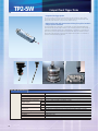
TP2-5W
Compact Touch Trigger Probe
• Compact touch trigger probes
This touch trigger probe has an outside diameter as small as ø13 mm, which greatly
contributes to probing complex portions of a workpiece. With the combined use of an
appropriate probe extension it can probe even deeper locations.
• Enhancing the setup and measurement efficiency through the automatic
change of probe orientation
Since the TP2-5W can be mounted on a probe head such as the PH10M/PH10MQ that
automatically changes the probe orientation, it can drastically reduce the time required to
prepare for measurement and for actual measurement in comparison to a conventionaltype scanning probe that has a fixed position downward. With the combined use of an
appropriate probe extension it can probe even deeper locations (when it is mounted on
the CNC coordinate measuring machine).
TP2-5W Specifications
TP2-5W
Measuring direction
Repeatability (2 )
Directionality (XY: 2D)
Directionality (XYZ: 3D)
Required force to generate
trigger signal
Amount of over-travel
Required force to achieve
over-travel
Stylus mounting method
Mass of single unit
Durability
Probe head
Applicable models
28
XY
Z
XY
Z
XY
Z
±X, ±Y, +Z
0.35µm or less
±0.8µm (with 10mm stylus), ±2.5µm (with the 50mm stylus)
±1µm (with 10mm stylus), ±4µm (with the 50mm stylus)
0.07 to 0.15N (Variable. Standard: 0.07N)
0.7N (when the X and Y axis are set to standard)
XY±14º, Z+4mm (when the required force to generate trigger signal is 0.07N)
±4mm (when the required force to generate trigger signal is 0.07N), +3mm (at 0.15N)
0.2 to 0.4N
4N (when the required force to generate trigger signal is 0.07N)
M2 screw
22g
1,000,000 times
Essential: PH10M/PH10MQ/MIH/PH1
Manual/CNC coordinate measuring machines
Compact Touch Trigger Probe
TP2-5W
Dimensions
ø13mm
3mm
38mm
M8
M2X0.4
Set configuration
No.
1
2
3
4
5
6
7
8
9
10
11
12
13
14
15
16
17
18
19
20
Description
Part No.
538414
932877A
06ABM152
06ABM153
06ABM154
—
—
—
—
135399
161534
161535
153140
908961
06AAN446
154613
TP2-5W
PH1 (ø14)
Carbon fiber extension bar
Stylus
Single-ended wrench
Double-ended wrench
MS2-stylus tool
Allen keys (4-piece set)
Storage box
User's Manual
Certificate
Signal cable
Signal cable
Signal cable
932878
935793
908462
Qty
Mass (kg)
0.022
1
0.125
1
0.024
1
0.057
1
0.086
1
0.0004
1
0.0004
1
0.0003
1
0.0005
1
0.0044
1
0.005
1
0.005
1
0.002
1
0.006
1 for each
1.3
1
0.1
1
0.01
1
0.2
* See the table below.
0.05
* See the table below.
0.05
* See the table below.
Remark
L=50mm
L=100mm
L=200mm
ø3X10mm standard stylus
ø2x20mm
ø1x10mm
ø3x20mm
Carbon fiber ball
For attaching/detaching the probe
For attaching/detaching the probe
For attaching/detaching the stylus
5P-5P straight, 5m
5P-5P curl code
5P-12P curl code
ø14
2
1
15
ø30
18
38
50
36
ø13
19
ø13
17
20
5
200
20
20
10
ø13
10
16
4
100
ø1
ø13
ø3
3
ø1"
ø2
50
Set order No.
06ABM328
06ABM329
06ABM330
06ABM155
14
13
Configuration Mass (kg)
No.1 - 18
1.948
No.1 - 17, 19
1.798
No.1 - 17, 20
1.798
No.1 - 17
1.748
11
6
12
7
8
17
10
ø3
9
Remark
With signal cable (5P-5P straight, 5m)
With signal cable (5P-5P curl code)
With signal cable (5P-12P curl code)
Signal cable: None
Unit : mm
TP2 kit [Order No. 916148]
4
6
5
Unit : mm
10
20
Qty
1
1
1
1
1
2
1 for each
1
1
3
20
Part No.
538414
—
—
—
—
153140
916149
916150
154613
2
10
Description
Touch trigger probe TP2-5W
Stylus ø3X10mm
Stylus ø2X20mm
Stylus ø1X10mm
Stylus ø3X20mm
Stylus tool S7
Allen keys (2 sizes)
Storage box
User's Manual
38
No.
1
2
3
4
5
6
7
8
9
1
ø13
ø1
ø3
ø2
7
ø3
8
9
29
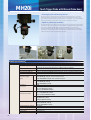
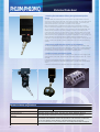
MH20i
Touch Trigger Probe with Manual Probe Head
• Touch trigger probe with manual probe head
This series of touch trigger probes has a manually operable probe head for coordinate
measuring machines. The probe module part has an outside diameter as small as ø13.2
mm, which greatly aids in probing complex portions of a workpiece. Other probe modules
employing an extension either 50 mm long or 70 mm long are also provided.
• Capable of positioning its orientation
The probe head part of the MH20i has a structure that not only permits its position (probe
orientation) to be manually changed but also provides a maximum of 168 orientations (at
a positioning repeatability σ≤1.5µm). Even for measurement of a complex threedimensional form that requires repeated changes in the probe orientation, preliminary
registration of required positions can eliminate re-calibration after each positional change,
thereby broadly improving the measurement efficiency.
MH20i Specifications
MH20i
30
±X, ±Y, +Z
Manually for A axis (vertical direction): 0 to 90º (at 15º increments),
and for B axis (horizontal direction): ±180º (at 15º increments)
≤1.5µm
Repeated positioning accuracy
0.35µm or less
Repeatability (2 )
±0.8µm or less (with the STANDARD FORCE 10mm stylus), ±2.5µm or less (with the 50mm stylus)
Directionality (XY: 2D)
±1µm or less (with the STANDARD FORCE 10mm stylus), ±4µm or less (with the 50mm stylus)
Directionality (XYZ: 3D)
XY 0.08N (STANDARD FORCE), with the 10mm stylus
Required force to
0.1N (MEDIUM FORCE), with the 25mm stylus
generate trigger
0.1N (EXTENDED FORCE), with the 50mm stylus
signal
0.75N (STANDARD FORCE)
Z
1.9N (MEDIUM FORCE)
3.2N (EXTENDED FORCE)
XY ±14º
Amount of
+4.0mm (STANDARD FORCE)
Z
over-travel
+3.7mm (MEDIUM FORCE)
+2.4mm (EXTENDED FORCE)
XY 0.2 - 0.3N (STANDARD FORCE)
Required force to
0.2 - 0.4N (MEDIUM FORCE)
achieve over-travel
0.2 to 0.5N (EXTENDED FORCE)
3.5N (STANDARD FORCE)
Z
7N (MEDIUM FORCE)
10N (EXTENDED FORCE)
50mm (STANDARD FORCE)
Maximum stylus length
60mm (MEDIUM FORCE)
60mm (EXTENDED FORCE)
M2 screw
Stylus mounting method
Mass of a single probe unit 250g
1,000,000 times
Durability
Not required
Probe head
Manual/CNC coordinate measuring machines
Applicable models
Measuring direction
Position change
Touch Trigger Probe with Manual Probe Head
MH20i
Dimensions
ø14mm
MH20i
MH20i
RENISHAW
77mm
MH20i
RENISHAW
53mm
MH20i
ø48mm
0
15
30
10mm 19.5mm
45
Probe module
5.7mm
Set Configuration
MH20i single unit
Order No.
06ABN436
MH20i set
Order No.
06ABN470
Ref. No.
1
2
3
4
5
6
7
8
9
Description
MH20i
Probe module
Cleaning tool
MS2-stylus tool
Positioning shank
Stylus
Allen key (2mm)
Allen key (3mm)
Operation Manual
Part No.
06ABN469
06AAV543
06AAL256
153140
160589
—
06AAA943
06AAA944
99MCA265J
5
MH20i
Qty
1
1
1
1
1
1
1
1
1
Mass (kg)
0.25
0.01
0.05
0.003
0.15
0.001
0.001
0.001
0.1
Remark
STANDARD TYPE
For cleaning the stylus module
For attaching/detaching the stylus
ø4X10 (standard stylus)
7
MH20i
RENISHAW
3
8
1
0
15
30
4
45
2
9
6
Optional accessories
Stylus module
Standard force module
Medium force module
Extended force module
EM1-STD
EM2-STD
31
MH20
Touch Trigger Probe with Manual Probe Head
• Compact touch trigger probe with manual probe head
This trigger probe has a manually operable probe head for coordinate measuring
machines. The probe module part has an outside diameter as small as ø13.2 mm, which
greatly aids in probing complex portions of a workpiece. Other probe modules employing
an extension either 50 mm long or 70 mm long are also provided.
• Easy position change
The operator can change the probe orientation in an optional direction by hand (simply
loosen the knob on the right-hand side and change the position, then re-fasten the knob).
No Allen key or other tools are required for the positional change.
MH20 Specifications
MH20
32
±X, ±Y, +Z
Manually for A axis (vertical direction): ±93º, and for B axis (horizontal direction):
To be fixed to optional direction in range of ±300º
0.35µm or less
Repeatability (2 )
±0.8µm or less (with the STANDARD FORCE 10mm stylus), ±2.5µm or less (with the 50mm stylus)
Directionality (XY: 2D)
±1µm or less (with the STANDARD FORCE 10mm stylus), ±4µm or less (with the 50mm stylus)
Directionality (XYZ: 3D)
XY 0.08N (STANDARD FORCE), with the 10mm stylus
Required force to
0.1N (MEDIUM FORCE), with the 25mm stylus
generate trigger
0.1N (EXTENDED FORCE), with the 50mm stylus
signal
Z
0.75N (STANDARD FORCE)
1.9N (MEDIUM FORCE)
3.2N (EXTENDED FORCE)
XY XY±14º
Amount of
Z
+4.0mm (STANDARD FORCE)
over-travel
+3.7mm (MEDIUM FORCE)
+2.4mm (EXTENDED FORCE)
XY 0.2 to 0.3N (STANDARD FORCE)
Required force to
0.2 to 0.4N (MEDIUM FORCE)
achieve over-travel
0.2 to 0.5N (EXTENDED FORCE)
Z
3.5N (STANDARD FORCE)
7N (MEDIUM FORCE)
10N (EXTENDED FORCE)
50mm (STANDARD FORCE)
Maximum stylus length
60mm (MEDIUM FORCE)
60mm (EXTENDED FORCE)
M2 screw
Stylus mounting method
Mass of a single probe unit 22g (Probe body: 13g, Probe modulel: 9g)
1,000,000 times
Durability
Essential: PH10M/PH10MQ/MIH/PH1
Probe head
Manual/CNC coordinate measuring machines
Applicable models
Measuring direction
Position change
Touch Trigger Probe with Manual Probe Head
MH20
Dimensions
ø14
Unit: mm
24
RENISHAW
90
47
MH20
Clamp
Center
10
º
93
º
93
Probe module
Rotating ±300º
Set Configuration
MH20-set
standard
configuration
Order No.
06AAZ727
No.
1
2
3
Description
1-1 MH20
MH20
1-2 TP20 standard module
kit No.
1-3 Stylus
06AAZ726 1-4 Cleaning kit
1-5 MS2-stylus tool
Operation Manual
Certificate
Part No.
06AAZ728
06AAV543
160217
06AAL256
153140
1-3
Mass (kg)
0.3
Remark
Probe head main unit
Measuring force (small)
ø4X10 (standard stylus)
For cleaning the probe module connection
Stylus attachment tool
0.1
0.01
1-4
MH20
RENISHAW
1-1
Qty
1
1
1
1
2
1
1
1-5
1-2
33
PH10M/PH10MQ
Motorized Probe Head
• Enhancing the measurement efficiency through automatic position
change
This probe head can automatically control the position of a probe attached at the end.
(This position change can be performed, during manual operation, by simply specifying the
angle through the supplied control box or the dedicated software, or by re-calling the
position from memory, if it has stored for automatic position change.)
When a polyhedral object is measured with a probe without the change of position
function, the following operation must be conducted: attach a cross-stylus, or multiple
styli, on the mount in order to measure the top surface with one facing downward, and
measure the side surface with one facing sideways. However, if the workpiece has a
complex geometry, probing to the target position may be obstructed because the unused
stylus can interfere with the workpiece. Also, the measuring operation in which the stylus
needs be attached at the specified angle may become problematic if position change is not
possible. Moreover, this automatic position change allows for measurement to be
completed in much less time than the automatic stylus change method, reducing the total
number of man-hours required to perform measurement with the coordinate measuring
machine.
• High-accuracy positioning with as many as 720 orientations
Since the PH10M/PH10MQ can set its position to a maximum of 720 orientations, even
one stylus can function as if 720 styli are attached. In addition, since this probe head has a
repeatability to the same position as high as 2σ≤0.5µm, it does not require re-calibration
for measurement in which the same position must be repeatedly called.
• Possible to mount various kinds of probe
At the end of this head various probes, including but not limited to a touch trigger probe,
scanning probe, vision probe, laser probe, and screw depth measuring probe, etc,. can be
mounted.
Furthermore, these probes can be easily replaced by means of the probe changer
(optional), which achieves full-automatic measurement on a wide range of measurement
objects.
* Note that some probes is not compatible with this automatic probe change.
PH10M/PH10MQ specifications
Position change
Repeated positioning accuracy
Mountable probe
Extension
Applicable models
34
Horizontal direction
180º (at 7.5º increments, 48 positions)
Vertical direction
0 to 105º (at 7.5º increments, 15 positions)
2 ≤0.5µm
MTP2000, TP7M, TP200, TP20, TP2-5W, QVP, SP25, SP600XE, MPP-10
Note that some combinations are prohibited on the same system.
PEM1, PEM2, PEM3, PAA1, PAA2, PAA3
More than one extension cannot be joined for use. However, combined
use of PAA+PFCF1, PAA1+PFCF2, and PAA1+PFCF3 are permitted.
Use on an extension is not permitted for the WIZprobe/LC50/LC100/QVP.
CNC coordinate measuring machines
Motorized Probe Head
PH10M/PH10MQ
PH10M dimensions
PH10MQ dimensions
73mm
62mm
ø14mm
73mm
38mm
38mm
130mm
PH10MQ adapter
80mm
Autojoint section
Autojoint section
Extensions
32mm
PAA1
50mm
PECF1
100mm
PECF2
200mm
PECF3
300mm
PAA3
50mm
PEM1
100mm
PEM2
200mm
PEM3
Set configuration
No.
PH10M
1 head set
Description
PH10M head
Joint key S10
Allen key (nominal 1.5)
Allen key (nominal 2)
Allen key (nominal 2.5)
PH10MQ head
Joint key S10
Allen key (nominal 1.5)
Allen key (nominal 2.5)
2
PH10MQ
head set
3
4
5
6
HCU-1
PHC10-2 (RS232C)
PAA1
User's Manual
Part No.
*
174748
908756
06AAA943
06AAA944
*
174748
908756
06AAA944
06AAN820
06AAR547
909460
99MCA034
Qty
Remark
Mass (kg)
1
1
1
2
1
1
1
1
1
2.0
2.0
Controller for positioning the probe head
Interface with the machine-side CPU (for error display)
Adapter for mounting the TP200 onto the PH10M
User's Manual for PH10M head
0.8
2.2
0.06
0.1
* Each part number will differ depending on the CMM main unit/probe that uses it. Some additional parts are also available.
1
2
3
4
PH
5
C1
0-2
6
35
MIH
Manual Probe Head
• High-accuracy positioning in a maximum of 720 orientations
The MIH has such a capability that permits its position (probe orientation) to be manually
changed to maximum 168 kinds of orientations at a positioning repeatability of σ≤1.5µm.
For measurement of a complex three-dimensional form that requires repeated changes in
the probe orientation, preliminary registration of required positions can eliminate recalibration after each positional change, therefore improving the measurement efficiency
at large. The current position can of course be confirmed on the LCD display of the MIH
main unit.
• Probe extensions up to 300 mm long
The MIH can employ any probe extension that is a maximum of 300 mm long. An example
combination of the TP2-5W and a 50 mm stylus can extend the probe’s reach to
approximately 400 mm.
MIH specifications
MIH
Position change
Repeated positioning accuracy
Mountable probe
Extension
Applicable models
36
Horizontal direction
±180º (at 7.5 increments, 48 positions)
Vertical direction
0 to 105º (at 7.5 increments, 15 positions)
≤1.5µm
TP200, TP20, TP2-5w
PAA1 (PAA1+PECF1, PAA1+PECF2, PAA1+PECF3), PAA2, PAA3
Manual coordinate measuring machines
Manual Probe Head
MIH
Dimensions
111mm
76.5mm
ø14mm
RENISHAW MIH
Autojoint section
ø62mm
Set configuration
Description
No.
MIH head
MIH
head kit
1 set
Order No. Joint key S10
06AAB126 Allen key (nominal 2)
Allen key (nominal 2.5)
Battery PX28L
Wooden box for MIH
2 PAA1
3 Single-ended wrench
4 Double-ended wrench
5 Positioning shank
6 Certificate
7 User's Manual
Part No. Mass (kg) Qty
06AAB127
1
1.5
174748
06AAA943
06AAA944
06AAB128
06AAB129
909460
0.06
161534
0.01
161535
0.005
160589
0.14
0.001
0.05
1
1
1
2
1
1
1
1
1
1
1
Remark
Traveling angle: Horizontal (B axis) ±180º (7.5º steps, 48 positions)
Vertical (A axis) 0 to 105º (7.5º steps, 15 positions)
Spatial positioning accuracy: ±0.3mm (where PAA1+TP2-5W+ø3 stylus+EWL7.5 is used)
Repeated positioning accuracy ( ): 1.5µm (in the same case as above)
Mass: Approx. 730g
For attaching the probe
For adjusting the positioning block, or battery replacement
For attaching the shank
6V lithium cell (Manufacturer: Duracell)
Adapter for connecting the MIH and probe. Length: 32mm
For fastening the TP2 and extension
For fastening the TP2 and extension
To be attached on the MIH head (Mitutoyo)
Optional accessories
Extensions
50mm
PECF1
100mm
PECF2
200mm
PECF3
200mm
PEL3
37
PH1
Manual Probe Head
• Manual probe head
Manual probe head for use with the TP200, TP20, and TP2-5W.
• Easy position change
The operator can change the probe orientation to an optional direction by hand.
• Extension
It is possible to insert a probe extension that is a maximum of 200 mm long.
PH1 specifications
Position change
Horizontal direction
Mountable probe
Extension
Applicable models
Vertical direction
TP200, TP20, TP2-5W
PECF1, PECF2, PECF3
Manual/CNC coordinate measuring machines
38
360º (at 15º increments)
Possible in a non-stop manner, if the head is rotated along with
the ø14mm shank unit.
±115º (non-step)
Manual Probe Head
PH1
Dimensions (when mounted on the TP2-5W)
ø41mm
50mm
36mm
ø14mm
M8
ø30mm
Optional accessories
Extensions
50mm
PECF1
100mm
PECF2
200mm
PECF3
An example connection of PECF3
39
ACR-3
• Necessity for automatic probe change
The ACR3 is an automatic probe changer for use with the PH10M/PH10MQ. It is essential
for full-automatic measurements where the currently employed probe does not have the
capability of automatic stylus change but the stylus diameter or length must be
occasionally changed, and where the contact-type probe and non-contact type probe are
switched as required.
Releasing
the lock
• Simplified structure
In comparison to the conventional automatic probe changer, which must have a dedicated
motor built in to turn on and off the lock system, is expensive, and has poor durability, the
ACR3 has a simplified structure and improved durability because it employs a new
mechanism in which the automatic probe change is performed through the CNC
coordinate measuring machine’s own drive system.
Engaging
the lock
Dimensions
Unit : mm
610
147
185
88.7
Free area
LOCKED
106
333
Free area
UNLOCKED
16
CENTER POSITION
Set configuration
4-port system
[Order No.
06ABP469]
8-port system
[Order No.
06ABP470]
40
No.
1
2
3
4
5
6
1
2
3
4
5
6
Description
ACR3
MRS KIT2
Auxiliary plate
ACR3 attachment
User's Manual
Control ROM
ACR3
MRS KIT2
Auxiliary plate
ACR3 attachment
User's Manual
Control ROM
Part No.
06ABN438
06ABN607
06ABG598
406ABP467
06ABN438
06ABN607
06ABG598
406ABP467
Qty Mass (kg)
1.5
1
3.5
1
8
1
0.05
1
0.1
1
0.01
1
1.5
2
3.5
1
8
1
0.05
1
0.1
1
0.01
1
Remark
4-port rack
Rack base
For fixture
Attachment
Adaptive to ACR3
4-port rack
Rack base
For fixture
Attachment
Adaptive to ACR3
1
3
2
4
Ceramic Master Ball
Ceramic master ball (standard type)
Ceramic master ball (high-accuracy type)
• Ball sphericity: 0.13µm or less
• Ball sphericity: 0.08µm or less
• Ball diameter dimensional tolerance: Sø20±0.01mm
• Ball diameter dimensional tolerance: Sø20 -0.02 mm
ø23
8.4
(12)
Part No 06ABM941
30
8.4
(12)
141
163
ø7.5
ø15
ø23
Part No 06ABM944
Unit : mm
Blue Line
M8X1.25
ø7.5
M8X1.25
ø20 ceramic ball
[Material: AI2O3 (99.9%)]
ø7 drill through
Unit : mm
ø15
ø20 ceramic ball
[Material: AI2O3 (99.9%)]
ø7 drill through
0
30
141
163
Base
Base for a ceramic master ball
141
191
Unit : mm
20
90.5
Base appearance
32
Ceramic ball attachment figure
Set break-downs
Set name
Ceramic
master ball
type
06ABQ041A
A set
Standard
06ABQ041B
A3 set
Standard
06ABQ040A
B set
Standard
06ABQ040B
B3 set
Standard
06ABQ044A
C set
High accuracy
06ABQ044B
C3 set
High accuracy
Set order No.
Inspection
Certificate
Base
Calibration
Traceability
Certificate
System Diagram
Optional accessory for the Ceramic Master Ball
Spacer
Spacer for the base
191
241
Unit : mm
90.5
Spacer appearance
20
32
Figure of attaching to Ceramic Master Ball + Base
41
Product Identification on Styli for Coordinate Measuring Machines
From each Mitutoyo styli the approximate form can be identified (see below).
1. Case of a ball stylus
MS 2 - 0.5 R 3 C
EWL
Mitutoyomanufactured stylus
Material of bar
Diameter of
mounting screw
Diameter of
ball tip
G: Carbon fiber
C: Ceramic
None: Other
Material of
probe tip
R: ruby
H: Carbide
Effective length
(EWL)
EWL: Effective working length where ball
does not interface with the bar.
2. Case of a cylindrical stylus
MS 2 - CY 3 R 6
Mitutoyomanufactured stylus
EWL
Effective length
(EWL)
Diameter of
mounting screw
Diameter of
cylinder
Material of probe tip
R: ruby
H: Carbide
- : other
Cylinder
3. Case of disc stylus
MS 2 - DISC 12 - 2
Mitutoyomanufactured stylus
Thickness of disc
Diameter of
mounting screw
Diameter of
disc
Disc dia.
Material of probe tip
Disc thickness
R: ruby
- : material other than ruby
Disc
4. Case of cross-stylus
MS 2 - STAR 2 R 2.5
Mitutoyomanufactured stylus
EWL
Effective length
(EWL)
Diameter of
mounting screw
Cross-stylus
Diameter of
ball
Material of probe tip
R: ruby
- : material other than ruby
5. Case of other materials
1. Point stylus
MS2-PO ("-H" will be added when the probe tip is carbide.)
2. Extension
MS2-EXT10 (the figure at the end represents the length. "G" is appended if the bar is
carbon fiber, and "C" is appended if the bar is ceramic.)
3. Stylus knuckle
MS2-stylus knuckle (an adapter for turning the stylus to the optional angle.)
4. Stylus center
MS-stylus center (an adapter to allow the styli to be mounted so they can be oriented
in directions crossing each other.)
42
Stylus (Mounting Thread dia: M2)
Carbide
ø1.4
ø3
Carbide
ø1.5
Mass: 0.3g
Carbide
ø0.3
Order No. : 06ABN752
Description : MS2-0.5R3
ø2 ruby ball
Mass: 0.4g
Order No. : 06ABN763
Description : MS2-2R22.5
ø0.3 ruby ball
10
14
20
ø3
2
M2X0.4
Stainless steel
M2X0.4
• Use with a measuring force 0.4N
or less.
• Cannot be mounted on TP200.
ø3
ø0.2
Order No. : 06ABN751
Description : MS2-0.3R2
Order No. : 06ABN762
Description : MS2-2R14
22.5
M2X0.4
ø2 ruby ball
30
ø3
Mass: 0.99g
10
Carbide
ø1.5
Order No. : 06ABN764
Description : MS2-2R32.5
ø0.5 ruby ball
• Cannot be mounted on TP200,
otherwise an input error may result.
ø3
3
M2X0.4
Mass: 0.3g
ø2 ruby ball
40
Mass: 1.29g
ø3
10
Mass: 0.3g
ø1.4
M2X0.4
ø2 ruby ball
52
Stainless steel
ø0.7
Order No. : 06ABN754
Description : MS2-1R4.5
Order No. : 06ABF406
Description : MS2-2R52
ø0.7 ruby ball
Carbide
ø3
4
M2X0.4
58
Mass: 1.5g
ø3
10
ø1
Mass: 0.3g
6
M2X0.4
Carbide
ø0.7
Order No. : 06ABN755
Description : MS2-1R7
Stainless steel
Order No. : 06ABN765
Description : MS2-2.5R6
ø1 ruby ball
ø2.5 ruby ball
10
ø3
Mass: 0.3g
20
Stainless steel
ø1.4
Order No. : 06ABN766
Description : MS2-2.5R14
ø1 ruby ball
ø3
7
M2X0.4
Mass: 0.6g
14
M2X0.4
Carbide
ø0.8
Order No. : 06ABN756
Description : MS2-1R12.5
ø2.5 ruby ball
20
ø3
Mass: 0.4g
20
ø2
Order No. : 06ABN767
Description : MS2-2.5R22.5
ø1 ruby ball
Carbide
ø3
12.5
M2X0.4
Mass: 0.41g
22.5
M2X0.4
Carbide
ø0.67
Order No. : 06ABN757
Description : MS2-1R20.5
ø2.5 ruby ball
30
ø3
Mass: 1.48g
ø2
Order No. : 06ABN768
Description : MS2-2.5R32.5
ø1 ruby ball
27.5
ø1 ruby ball
ø3
32.5
M2X0.4
• Cannot be mounted on TP200,
otherwise an input error may
result.
Mass: 1.95g
ø1.5
Order No. : 06ABN769
Description : MS2-3R7.5
37
Mass: 0.9g
ø0.7
7.5
M2X0.4
Stainless steel
ø3
10
10
ø3 ruby ball
Mass: 0.4g
Stainless steel
Mass: 0.3g
17.5
M2X0.4
Carbide
ø3 ruby ball
20
Mass: 0.5g
ø3
ø1
Order No. : 06ABN759
Description : MS2-1.5R12.5
Order No. : 06ABN770
Description : MS2-3R17.5
ø1.5
ø1.5 ruby ball
Stainless steel
ø3
4.5
ø2.5 ruby ball
40
ø3
ø0.7
Carbide
M2X0.4
• Cannot be mounted on TP200,
otherwise an input error may result.
Mass: 0.4g
52
Order No. : 06ABN758
Description : MS2-1.5R4.5
Carbide
ø3
20.5
M2X0.4
M2X0.4
• Cannot be mounted on TP200,
otherwise an input error may result.
• For other probes it is recommended
to use in the vertical direction,
otherwise an input error may result
depending on the drive speed or
acceleration.
ø3
4.5
M2X0.4
Order No. : 06ABF409
Description : MS2-1R37
32.5
M2X0.4
Carbide
ø0.5
Order No. : 06ABN753
Description : MS2-0.7R4
20
Order No. : 06ABN771
Description : MS2-3R27.5
Carbide
ø2
ø1.5 ruby ball
ø3
12.5
M2X0.4
Mass: 0.46g
ø1
ø3 ruby ball
30
Mass: 1.49g
Order No. : 06ABN772
Description : MS2-3R37.5
Mass: 0.58g
37.5
M2X0.4
Stainless steel
ø1
• Cannot be mounted on TP200,
otherwise an input error may result.
Carbide
ø2
ø1.5 ruby ball
30
ø3
22.5
M2X0.4
ø3 ruby ball
40
Mass: 1.97g
ø3
ø2 ruby ball
10
Order No. : 06ABN773
Description : MS2-3R47.5
Carbide
ø2
6
M2X0.4
• Cannot be mounted on TP200,
otherwise an input error may result.
ø3
Order No. : 06ABN761
Description : MS2-2R6
27.5
M2X0.4
Carbide
ø3
Order No. : 06ABN760
Description : MS2-1.5R22.5
Mass: 0.3g
M2X0.4
47.5
ø3 ruby ball
50
Mass: 2.44g
43
Ceramic
ø3 ruby ball
ø3
ø2
M2X0.4
68.5
83.5
Mass: 1.6g
10
M2X0.4
ø5 ruby ball
ø2.5
Mass: 2.57g
Order No. : 06ABN783
Description : MS2-5R40
40
ø5 ruby ball
Mass: 3.17g
Carbide
ø4 ruby ball
50
M2X0.4
Mass: 3.75g
ø3
ø1.5
ø3
Ceramic
ø2.5
Order No. : 06ABN785
Description : MS2-5R50C
Stainless steel
20
M2X0.4
ø4 ruby ball
50
M2X0.4
ø5 ruby ball
Mass: 0.6g
Order No. : 06ABN776
Description : MS2-4R30
• Cannot be mounted on TP200,
otherwise an input error may result.
ø5 ruby ball
Mass: 0.4g
Order No. : 06ABN775
Description : MS2-4R20
• Cannot be mounted on TP200,
otherwise an input error may result.
Carbide
M2X0.4
Order No. : 06ABN784
Description : MS2-5R50
Stainless steel
ø3
ø1.5
Order No. : 06ABN774
Description : MS2-4R10
• Cannot be mounted on TP200,
otherwise an input error may result.
• For other probes it is recommended
to use in the vertical direction,
otherwise an input error may result
depending on the drive speed or
acceleration.
30
M2X0.4
ø2.5
Order No. : 06ABF405
Description : MS2-3R68.5C
Mass: 1.3g
Carbide
ø2.5
ø1.5
ø3
64
68
Order No. : 06ABN782
Description : MS2-5R30
ø3
• Cannot be mounted on TP200,
otherwise an input error may result.
• For other probes it is recommended
to use in the vertical direction,
otherwise an input error may result
depending on the drive speed or
acceleration.
ø3 ruby ball
Stainless steel
ø3
M2X0.4
ø3
Order No. : 06ABF402
Description : MS2-3R64
Mass: 1.0g
Order No. : 06ABQ342
Description : MS2-5R50.5G
Carbon fiber
M2X0.4
ø5 ruby ball
ø3
ø3
ø2
Carbide
30
M2X0.4
ø4 ruby ball
50.5
Mass: 1.57g
Order No. : 06ABN777
Description : MS2-4R40
• Cannot be mounted on TP200,
otherwise an input error may result.
Order No. : 06ABF411
Description : MS2-5R97.5C
Ceramic
ø3
ø3
ø2
Carbide
Mass: 1.1g
40
M2X0.4
ø4 ruby ball
97.5
M2X0.4
ø5 ruby ball
Mass: 2.04g
ø2
ø3
50
M2X0.4
Order No. : 06ABN786
Description : MS2-6R10
ø2.5
• Cannot be mounted on TP200,
otherwise an input error may result.
Carbide
ø4 ruby ball
10
M2X0.4
Mass: 2.52g
Order No. : 06ABN779
Description : MS2-4R50C
Stainless steel
ø3
Order No. : 06ABN778
Description : MS2-4R50
Mass: 2.1g
ø6 ruby ball
Mass: 0.9g
Order No. : 06ABN787
Description : MS2-6R50.5G
Carbon fiber
M2X0.4
50
M2X0.4
ø4 ruby ball
50.5
Mass: 0.91g
Carbon fiber
Order No. : 06ABN788
Description : MS2-8R11
ø4 ruby ball
ø3
ø3
M2X0.4
Mass: 1.2g
Stainless steel
ø2.5
Order No. : 06ABQ341
Description : MS2-4R50.5G
M2X0.4
50.5
Stainless steel
• Cannot be mounted on TP200,
otherwise an input error may result.
• For other probes it is recommended
to use in the vertical direction,
otherwise an input error may result
depending on the drive speed or
acceleration.
ø4 ruby ball
ø3
ø2
M2X0.4
68
Order No. : 06ABF410
Description : MS2-4R98C
Mass: 2.0g
ø4 ruby ball
Ceramic
ø3
M2X0.4
98
Mass: 2.5g
Stainless steel
ø3
ø2.5
Order No. : 06ABN780
Description : MS2-5R10
M2X0.4
10
ø5 ruby ball
Carbide
ø3
Order No. : 06ABN781
Description : MS2-5R20
ø2.5
Mass: 0.7g
M2X0.4
20
ø5 ruby ball
Mass: 1.98g
44
11
ø8 ruby ball
Mass: 1.5g
Mass: 1.0g
Order No. : 06ABF404
Description : MS2-4R68
ø6 ruby ball
ø3
ø3
ø2
Ceramic
• Cannot be mounted on TP200,
otherwise an input error may result.
• For other probes it is recommended
to use in the vertical direction,
otherwise an input error may result
depending on the drive speed or
acceleration.
• Cannot be mounted on TP200,
otherwise an input error may result.
• For other probes it is recommended
to use in the vertical direction,
otherwise an input error may result
depending on the drive speed or
acceleration.
Stylus (Mounting thread dia.: M2)
Order No. : 06ABN793
Description : MS2-CY2H31
Carbide
• Cannot be mounted on TP200,
otherwise an input error may result.
ø3
ø2
31
18.05
3
13.05
39
M2X0.4
Carbon
fiber
Mass: 2.0g
.05
ø19 /4")
(3
M2X0.4
ø2
Ruby
ø4
ø3
Order No. : 06ABN794
Description : MS2-CY4R8.5
ø3
Order No. : 135399
Description : MS2-19.05C 3/4inch
Mass: 4.4g
8.5
M2X0.4
ø18
20
ø4
Mass: 0.9g
2.2
0.4
M2X0.4
11
Order No. : 160225
Description : MS2-18C
8
Stainless steel
ø3
ø1
Order No. : 06ABN799
Description : MS2-PO
Mass: 3.3g
Ceramic
15
M2X0.4
Mass: 0.7g
2.5
5
M2X0.4
ø1 ruby ball
Order No. : 06ABN800
Description : MS2-PO-H
Carbide
M2X0.4
.1
M2X0.4
10
ø3
ø1.4
R0
ø0.67
7.5
ø3
3
Order No. : 06ABN795
Description : MS2-STAR1R2.5
10
Mass: 0.7g
Mass: 0.5g
18
5.5
M2X0.4
Order No. : 160214
Description : MS2-DISC6R2
5.25
10
2
ø3
ø2
ø2 ruby ball
ø6
ru
by
ba
ll
Order No. : 06ABN796
Description : MS2-STAR2R5.25
10.7
Mass: 1.3g
Order No. : 06AAL516
Description : MS2-DISC18-2.5
1.5
Stainless
steel
30
5.5
10.75
ø3
M2X0.4
8.2
ø18
Order No. : 06ABN797
Description : MS2-STAR2R10.75
Mass: 0.6g
18
ø2
ø1.4
1.2
M2X0.4
ø2 ruby ball
M2X0.4
Mass: 3.0g
10.7
18
ø2
ø1.4
2.5
Mass: 1.8g
Order No. : 06ABN789
Description : MS2-CY1.5-1.7
Order No. : 160215
Description : MS2-DISC18-3
2.6
2.2
M2X0.4
ø3
ø1
ø1.5
ø18
Stainless steel
3
1.7
Mass: 2.7g
11
Mass: 0.3g
Order No. : 06ABN790
Description : MS2-CY3-4
1.5
Stainless
steel
Stainless steel
ø3
ø3
ø3
ø1.5
8.2
Order No. : 06AAL517
Description : MS2-DISC25-2.5
ø25
M2X0.4
4
M2X0.4
M2X0.4
13
2.5
Mass: 0.6g
Order No. : 06ABN791
Description : MS2-CY1R7.5
2.5
Order No. : 160226
Description : MS2-DISC25-3
Ruby
Mass: 4.0g
3
ø3
ø1
7.5
14.5
ø25
M2X0.4
Mass: 0.3g
M2X0.4
Mass: 3.8g
Ruby
ø2
ø3
ø1.5
Order No. : 06ABN792
Description : MS2-CY2R6.5
6.5
M2X0.4
20
Mass: 0.5g
45
Stylus (Mounting screw dia.: M2)
Order No. : 908886
Description : MS2-EXT60C
ø3
Ceramics
Order No. : 06ABP853
Description : MS2-EXT5
60
M2X0.4
M2X0.4
Stainless steel
ø3
Mass: 1.3g
Order No. : 06ABN809
Description : MS2-EXT70G
M2X0.4
Mass: 0.2g
• Not recommended to mounted on
TP200, otherwise an input error
may result.
• Also for other probes it is
recommended to use in the vertical
direction. Otherwise an input error
may result depending on the drive
speed or acceleration.
ø3.55
5
Carbon fiber
ø3
M2X0.4
Order No. : 06ABN804
Description : MS2-EXT10
70
M2X0.4
11.55
Stainless steel
ø3
Mass: 1.3g
10
Order No. : 908887
Description : MS2-EXT80C
M2X0.4
Mass: 0.4g
Ceramics
ø3
M2X0.4
Order No. : 06ABN805
Description : MS2-EXT20
80
M2X0.4
M2X0.4
Stainless steel
M2X0.4
20
Order No. : 06ABN810
Description : MS2-EXT90G
M2X0.4
Carbon fiber
ø3
Mass: 0.9g
ø3.55
ø3
Mass: 1.6g
Order No. : 908884
Description : MS2-EXT20C
90
M2X0.4
Ceramics
11.55
ø3
Mass: 1.5g
• Cannot be mounted on TP200,
otherwise an input error may result.
• Also for other probes it is
recommended to use in the vertical
direction, otherwise an input error
may result depending on the drive
speed or acceleration.
M2X0.4
20
Order No. : 153142
Description : MS2-stylus knuckle
M2X0.4
Mass: 0.7g
4.5
M2X0.4
• Adapter for turning the stylus in
the optional direction.
8
Stainless steel
Order No. : 06ABN806
Description : MS2-EXT30
Stainless steel
Stainless steel
Mass: 1.6g
ø3
M2X0.4
Order No. : 06ABN812
Description : MS2-stylus center
M2X0.4
Mass: 1.4g
7
Order No. : 06ABN807
Description : MS2-EXT40
M2X0.4
Stainless steel
4-M2X0.4
Stainless steel
ø3
M2X0.4
Mass: 0.8g
40
M2X0.4
Mass: 1.8g
Order No. : 06ABN813
Description : MS2-M3 female-adapter
Stainless steel
ø4
M2X0.4
Order No. : 908885
Description : MS2-EXT40C
M2X0.4
7
M3X0.5
Ceramics
ø3
Mass: 0.4g
M2X0.4
40
M2X0.4
Mass: 1.0g
• For TP200
ø3
Carbon fiber
ø3.55
Order No. : 06AAL257
Description : MS2-EXT40G
M2X0.4
40
11.55
Mass: 0.9g
• For TP200
ø3
Carbon fiber
ø3.55
Order No. : 06AAL258
Description : MS2-EXT50G
M2X0.4
50
11.55
Mass: 1.0g
46
• Adapter for turning the stylus in
one of the five
directions.
6
30
7.5
M2X0.4
• This is an adapter for a probe,
whose stylus attachment section is
threaded to M2,
M2
to accept M3-screw
stylus.
M3
M3X0.5
ø2 ruby ball
Carbide
ø4
Order No. : 06ABF416
Description : MS3-2R62.5
ø1.5
Stylus (Mounting thread dia.: M3)
Order No. : 06ABN816
Description : MS3-0.5R2
ø0.5 ruby ball
ø0.35
M3X0.5
• Use with a measuring
force 0.4N or less.
62.5
69
ø4
Mass: 2.2g
Carbide
20
Order No. : 06ABN823
Description : MS3-3R12
ø3 ruby ball
Stainless steel
M3X0.5
ø4
Mass: 1.0g
ø1.5
2
Order No. : 06ABN817
Description : MS3-1R4
M3X0.5
ø1 ruby ball
Stainless steel
12
Mass: 1.0g
ø4
ø0.7
21
Order No. : 06ABN824
Description : MS3-3R22.5
M3X0.5
ø3 ruby ball
Carbide
ø4
Mass: 1.0g
ø2
4
21
M3X0.5
Carbide
22.5
ø1 ruby ball
30
Mass: 1.83g
ø4
ø0.8
Order No. : 06ABF414
Description : MS3-1R12
12
Order No. : 06ABN825
Description : MS3-3R32.5
ø3 ruby ball
Carbide
M3X0.5
ø4
Mass: 1.0g
ø2
22
32.5
ø1 ruby ball
Carbide
40
ø4
ø0.8
M3X0.5
25
32
Order No. : 06ABN826
Description : MS3-3R42.5
M3X0.5
ø3 ruby ball
Carbide
ø4
Mass: 0.9g
Mass: 2.3g
ø2
Order No. : 06ABF412
Description : MS3-1R25
Order No. : 06ABN818
Description : MS3-1.5R12.5
42.5
ø1.5 ruby ball
Carbide
50
Mass: 2.78g
ø4
ø1
M3X0.5
Order No. : 06ABF415
Description : MS3-3R50
ø3 ruby ball
Carbide
M3X0.5
ø4
Mass: 0.8g
ø2
12.5
20
Order No. : 06ABN819
Description : MS3-1.5R22.5
M3X0.5
ø1.5 ruby ball
Carbide
50
Mass: 3.5g
ø4
ø1
64
Order No. : 06ABN820
Description : MS3-2R8
ø2 ruby ball
Stainless steel
ø4 ruby ball
Stainless
steel
ø2.5
M3X0.5
ø1.4
M3X0.5
Mass: 0.93g
Order No. : 06ABN827
Description : MS3-4R17
ø4
22.5
30
17
ø4
21
Mass: 1.3g
8
Mass: 1.0g
Order No. : 06ABN821
Description : MS3-2R22.5
Carbide
M3X0.5
Stainless
steel
ø4 ruby ball
ø2 ruby ball
ø4
ø1.5
ø4
M3X0.5
Order No. : 06ABN828
Description : MS3-4R27
ø2.5
21
27
31
Mass: 2.5g
22.5
30
Carbide
ø2 ruby ball
Order No. : 06ABN829
Description : MS3-4R36
Carbide
M3X0.5
ø4 ruby ball
ø1.5
ø2
M3X0.5
ø4
ø4
Order No. : 06ABN822
Description : MS3-2R32.5
Mass: 1.32g
32.5
40
36
Mass: 1.58g
40
Mass: 2.38g
47
M3X0.5
ø4 ruby ball
Carbide
Order No. : 169011
Description : MS3-DISC12.7-2
Stainless
steel
M3X0.5
2
ø4
ø12.7
ø4
ø3
ø2
Order No. : 06ABN830
Description : MS3-4R46
46
31
50
Order No. : 06ABF403
Description : MS3-4R53
Mass: 4.0g
Mass: 2.85g
M3X0.5
Order No. : 06ABN833
Description : MS3-EXT10
ø4 ruby ball
Stainless
steel
ø4
ø4
ø2
Carbide
53
Mass: 0.9g
Order No. : 06ABN834
Description : MS3-EXT20
ø5 ruby ball
Stainless
steel
ø4
Stainless
steel
ø4
M3X0.5
M3X0.5
Mass: 3.0g
ø2.5
Order No. : 06ABN831
Description : MS3-5R21
10
M3X0.5
57
20
M3X0.5
21
Order No. : 163874
Description : MS3-5R31
M3X0.5
M3X0.5
Mass: 1.6g
Mass: 1.5g
Order No. : 06ABN835
Description : MS3-EXT35
ø5 ruby ball
Stainless
steel
ø4
ø4
ø3
Stainless
steel
35
M3X0.5
31
Order No. : 06ABN832
Description : MS3-5R50C
Ceramics
Mass: 2.9g
Order No. : 06ABN836
Description : MS3-EXT50C
ø5 ruby ball
Ceramics
ø4
ø4
ø2.5
M3X0.5
M3X0.5
Mass: 3.0g
50
M3X0.5
50
Mass: 2.95g
ø6 ruby ball
• For SP25M
Order No. : 06ABS915
Description : MS3-EXT75G
ø4
11.5
M3X0.5
13
75
M3X0.5
75
Mass: 2.4g
• For SP25M
Order No. : 06ABS916
Description : MS3-EXT100G
• For SP25M
Carbon
fiber
ø4
ø6 ruby ball
Carbon fiber
ø4.55
M3X0.5
Mass: 2.53g
M3X0.5
ø4
ø4
Order No. : 06ABS912
Description : MS3-6R100G
• For SP25M
Carbon
fiber
ø4
Carbon fiber
ø4
M3X0.5
ø4.55
Order No. : 06ABS911
Description : MS3-6R75G
M3X0.5
Mass: 1.33g
11.5
13
100
M3X0.5
100
Mass: 3.02g
Mass: 2.89g
Order No. : 06ABS913
Description : MS3-8R75G
M3X0.5
ø8 ruby ball
• For SP25M
Order No. : 06ABN838
Description : MS3-stylus knuckle
• Adapter for turning the stylus in
the optional direction.
3.5
Stainless
steel
M3X0.5
Stainless
steel
8
ø4
3.8
Carbon fiber
6
75
ø4
M3X0.5
Mass: 3.7g
Mass: 2.98g
M3X0.5
ø8 ruby ball
Carbon fiber
• For SP25M
Order No. : 06ABN839
Description : MS3-stylus center
M3X0.5
• Adapter for turning the stylus in
one of the five
directions.
10
Stainless
steel
5.5
13
ø4
Order No. : 06ABS914
Description : MS3-8R100G
100
Mass: 3.47g
Description : MS3-8R130C
M3X0.5
ø8 ruby ball
ø6
ø4
Ceramics
130
Mass: 9.4g
ø30
Order No. : 916492
Description : MS3-30C
• Cannot be mounted on the old
scanning probe models including
MPP-2, MPP-2H, and MPP-5.
• Strongly recommended to use
in the vertical position for touch
trigger probes. Otherwise an
input error may result depending
on the drive speed or acceleration.
Order No. : 06ABN837
Description : MS3-M2 female-adapter
• This is an adapter for a probe,
whose stylus attachment
section is threaded to
M4, to accept M2-screw
stylus.
Stainless
steel
M3X0.5
5
• This is an adapter for a probe,
whose stylus attachment
section is threaded to
M3
M3, to accept
ø4.5 straight
straight-shank type
stylus.
48
10
ø4.5
ø9
17
Ceramics
M2
M2X0.4
Stainless
steel
M3X0.5
Mass: 18g
M4
Mass: 0.6g
Order No. : 167234
Description : MS3-ø4.5-adapter
M3X0.5
Mass: 2.4g
ø4
Order No. : 06ABF407
M3X0.5
Mass: 2.3g
Stylus (Mounting thread dia.: M4)
Description: MS4-EXT200C
Ceramics
• Dedicated for TP800.
ø7
Code No.: 06AAD457
M4X0.7
Stainless
steel
Mass: 16.6g
Order No. : 06ABN851
Description : MS4-M3EXT20
ø7
4.5
19.5
Stainless
steel
Stainless
steel
ø7
Mass: 2.5 g
M4X0.7
M3X0.5
M4X0.7
ø2 ruby ball
20
Mass: 3.2g
ø7
ø1.35
Order No. : 06ABN841
Description : MS4-2R8
M4X0.7
200
ø1 ruby ball
ø0.7
M4X0.7
ø5
Order No. : 06ABN840
Description : MS4-1R4.5
Ceramics
19
ø7
Order No. : 06ABN852
Description : MS4-M3EXT50C
8
Mass: 2.3 g
M3X0.5
M4X0.7
Order No. : 06ABN842
Description : MS4-4R13.5
ø4 ruby ball
Stainless
steel
Mass: 4.4g
ø7
ø3
M4X0.7
50
Ceramics
18
ø7
Order No. : 06ABN853
Description : MS4-M3EXT75C
13.5
Mass: 2.1 g
M3X0.5
M4X0.7
75
Mass: 5.2g
ø7
ø3
Order No. : 06ABQ149
Description : MS4-4R33C
ø4 ruby ball
Ceramics
M4X0.7
Order No. : 06ABN854
Description : MS4-M3EXT100C
33
50
ø7
Mass: 4.8 g
• Cannot be mounted on
MTP2000.
Ceramics
M3X0.5
M4X0.7
ø8 ruby ball
Ceramics
M4X0.7
100
ø4.5
Order No. : 06ABN843
Description : MS4-8R50C
ø7
Mass: 6.3g
50
Order No. : 06AAD460
Description : MS4-stylus knuckle
Stainless
steel
M4X0.7
Stainless
steel
15
Mass: 5.1 g
4.5
9
Ceramics
ø8 ruby ball
M4X0.7
ø4.5
M4X0.7
Mass: 14.5g
ø7
100
Stainless
steel
ø6 ruby ball
ø4.4
Carbon fiber
ø7
100
ø4.4
Stainless
steel
9
• This is an adapter for
a probe, whose stylus
attachment section is
threaded to M4,
accept M3-screw stylus.
M4
M3
Mass: 1.4g
ø6 ruby ball
Carbon fiber
ø7
Order No. : 06ABN856
Description : MS4-M2 female-adapter
ø7
Stainless
steel
Mass: 7.5 g
M4X0.7
• Cannot be mounted
on MTP2000 or
TP7M.
Description: MS4-6R188G
ø6 ruby ball
Carbon fiber
5
M2X0.4
• This is an adapter for
a probe, whose stylus
attachment section is
threaded to M4,
accept M2-screw stylus.
M4
M2
Mass: 1.5g
ø7
ø4.5
M3X0.5
M4X0.7
• Cannot be mounted
on MTP2000.
Description: MS4-6R138G
150
M4X0.7
M4X0.7
ø7
Mass: 6.2 g
138
Order No. : 06ABN847
• Adapter for mounting
the stylus
in the five
positions.
Mass: 12.1g
Order No. : 06ABN855
Description : MS4-M3 female-adapter
88
M4X0.7
4-M4X0.7
9
16
M4X0.7
M4X0.7
Mass: 6.6 g
12.5
Order No. : 06ABN845
Description : MS4-6R88G
Order No. : 06ABN846
15
Order No. : 06ABN857
Description : MS4-stylus center
ø5
Order No. : 06ABN844
Description : MS4-8R100C
• Adapter for
turning the stylus
in the optional
direction.
188
200
Mass: 8.7 g
Ceramics
ø7
Order No. : 06ABN848
Description : MS4-EXT30C
M4X0.7
M4X0.7
30
Mass: 5.1 g
Order No. : 06ABN849
Description : MS4-EXT50C
ø7
Ceramics
M4X0.7
M4X0.7
50
Mass: 6.7 g
Order No. : 06ABN850
Description : MS4-EXT100C
• Cannot be mounted
on MTP2000.
ø7
Ceramics
M4X0.7
100
M4X0.7
Mass: 10.6 g
49
Stylus (Mounting screw dia.: M5)
20
Order No. : 06ABS917
Description : MS5-0.5R4
4
55
• Dedicated for SP80.
ø0.5 ruby ball
Order No. : 06ABS933
Description : MS5-4R11G
5
5
30
Order No. : 06ABS934
Description : MS5-4R21G
• Dedicated for SP80.
ø0.7
50
Order No. : 06ABS935
Description : MS5-4R41G
ø2
ø4 ruby ball
ø1
ø1.5 ruby ball
Mass: 4.79g
Carbon fiber
20
• Dedicated for SP80.
11
• Dedicated for SP80.
100
M5X0.8
50
ø2 ruby ball
ø1
M5X0.8
Order No. : 06ABS936
Description : MS5-4R50G
ø3
Mass: 4.68g
Carbide
Order No. : 06ABS923
Description : MS5-2R11
• Dedicated for SP80.
41
M5X0.8
• Dedicated for SP80.
11
Mass: 4.69g
Carbon fiber
20
M5X0.8
ø4 ruby ball
ø1 ruby ball
Mass: 6.52g
Carbide
• Dedicated for SP80.
21
M5X0.8
ø2
20
M5X0.8
Mass: 4.65g
Carbon fiber
Mass: 6.5g
Carbide
Order No. : 06ABS921
Description : MS5-1.5R11
Carbon fiber
30
• Dedicated for SP80.
21
Mass: 18.00g
75
Order No. : 06ABS937
Description : MS5-4R65G
• Dedicated for SP80.
65
M5X0.8
ø4 ruby ball
ø2 ruby ball
ø1
M5X0.8
ø4 ruby ball
ø3
Mass: 4.70g
Carbide
Order No. : 06ABS924
Description : MS5-2R21
• Dedicated for SP80.
ø4 ruby ball
• Dedicated for SP80.
ø0.7 ruby ball
ø0.5
M5X0.8
Order No. : 06ABS920
Description : MS5-1R5
11
M5X0.8
ø2
20
Order No. : 06ABS918
Description : MS5-0.7R5
Mass: 16.30g
20
Mass: 6.5g
Carbide
ø3 ruby ball
Carbide
ø0.4
M5X0.8
• Dedicated for SP80.
100
M5X0.8
ø1.5
Order No. : 06ABS932
Description : MS5-3R55
Mass: 5.32g
Carbon fiber
Mass: 4.81g
40
• Dedicated for SP80.
31
M5X0.8
Order No. : 06ABS938
Description : MS5-5R11G
• Dedicated for SP80.
11
M5X0.8
ø2 ruby ball
ø5 ruby ball
ø1
Order No. : 06ABS925
Description : MS5-2R31
20
ø3
Carbide
Mass: 4.82g
Carbon fiber
Mass: 4.93g
Carbide
40
• Dedicated for SP80.
31
ø2.5 ruby ball
• Dedicated for SP80.
21
M5X0.8
ø5 ruby ball
ø3
M5X0.8
Order No. : 06ABS939
Description : MS5-5R21G
ø1.5
Order No. : 06ABS926
Description : MS5-2.5R31
30
Carbon fiber
50
• Dedicated for SP80.
41
ø2.5 ruby ball
Order No. : 06ABS940
Description : MS5-5R41G
41
M5X0.8
• Dedicated for SP80.
ø5 ruby ball
ø3
50
M5X0.8
ø2
Order No. : 06ABS927
Description : MS5-2.5R41G
Mass: 4.92g
Mass: 5.40g
Carbide
• Dedicated for SP80.
20
M5X0.8
ø3 ruby ball
11
Order No. : 06ABS941
Description : MS5-5R50G
100
ø2
Carbon fiber
Mass: 4.57g
30
• Dedicated for SP80.
21
ø3 ruby ball
Order No. : 06ABS942
Description : MS5-5R65G
65
M5X0.8
ø2
• Dedicated for SP80.
31
M5X0.8
ø3 ruby ball
ø2
Order No. : 06ABS930
Description : MS5-3R31G
Carbon fiber
Mass: 4.62g
40
Carbon fiber
Mass: 5.42g
100
M5X0.8
41
Carbon fiber
Carbon fiber
ø3 ruby ball
Order No. : 06ABS944
Description : MS5-6R39G
ø5 ruby ball
50
Mass: 4.72g
Mass: 5.69g
• Dedicated for SP80.
39
M5X0.8
Carbon fiber
50
• Dedicated for SP80.
91
• Dedicated for SP80.
50
M5X0.8
Order No. : 06ABS943
Description : MS5-5R91G
• Dedicated for SP80.
Mass: 4.67g
ø2
Order No. : 06ABS931
Description : MS5-3R41G
ø5 ruby ball
ø3
Carbon fiber
Mass: 18.15g
ø6 ruby ball
ø4.3
M5X0.8
ø5 ruby ball
75
ø3
Carbon fiber
Order No. : 06ABS929
Description : MS5-3R21G
• Dedicated for SP80.
50
M5X0.8
ø3
Order No. : 06ABS928
Description : MS5-3R11G
Mass: 5.14g
Carbon fiber
Mass: 4.71g
Carbon fiber
Mass: 6.10g
75
Order No. : 06ABS945
Description : MS5-6R64G
• Dedicated for SP80.
64
ø6 ruby ball
Order No. : 06ABS957
Description : MS5-EXT60G
• Dedicated for
SP80.
60
Carbon fiber
M5X0.8
ø11
ø4
M5X0.8
100
• Dedicated for SP80.
M5X0.8
89
• Dedicated for
SP80.
70
Order No. : 06ABS958
Description : MS5-EXT70G
M5X0.8
Carbon fiber
ø11
ø4
Order No. : 06ABS946
Description : MS5-6R89G
Mass: 9.0g
Mass: 6.59g
Carbon fiber
Carbon fiber
ø6 ruby ball
50
Order No. : 06ABS947
Description : MS5-8R37G
Mass: 9.7g
Mass: 7.08g
• Dedicated for SP80.
37
ø8 ruby ball
80
Order No. : 06ABS959
Description : MS5-EXT80G
M5X0.8
• Dedicated for
SP80.
Carbon fiber
ø11
ø6
M5X0.8
Mass: 10.4g
Mass: 7.96g
Carbon fiber
M5X0.8
Order No. : 06ABU673
Description : MS5-8R38C
• Dedicated for SP80.
ø8 ruby ball
90
Order No. : 06ABS960
Description : MS5-EXT90G
• Dedicated for
SP80.
Carbon fiber
M5X0.8
ø11
ø19
ø6
Ceramics
38
Mass: 30g
60
75
Order No. : 06ABS948
Description : MS5-8R62G
• Dedicated for SP80.
62
ø8 ruby ball
Order No. : 06ABS961
Description : MS5-EXT100G
100
M5X0.8
• Dedicated for
SP80.
Carbon fiber
ø11
ø6
M5X0.8
Mass: 11.1g
Carbon fiber
M5X0.8
• Dedicated for SP80.
87
Order No. : 06ABS962
Description: MS5-EXT120G
120
M5X0.8
• Dedicated for
SP80.
Carbon fiber
ø11
ø6
Order No. : 06ABS949
Description : MS5-8R87G
Mass: 11.8g
Mass: 9.06g
100
Carbon fiber
ø8 ruby ball
Order No. : 06ABS950
Description : MS5-10R37G
37
M5X0.8
Mass: 13.2g
Mass: 10.17g
50
• Dedicated for SP80.
ø10 ruby ball
Order No. : 06ABS963
Description: MS5-EXT150G
150
Carbon fiber
• Dedicated for
SP80.
ø11
ø6
M5X0.8
Mass: 8.91g
Carbon fiber
Mass: 15.4g
75
Order No. : 06ABS951
Description : MS5-10R62G
62
M5X0.8
ø10 ruby ball
• Dedicated for SP80.
Order No. : 06ABS964
Description: MS5-EXT180G
M5X0.8
• Dedicated for
SP80.
Mass: 18.9g
• Dedicated for
SP80.
Mass: 22.4g
• Dedicated for
SP80.
Mass: 25.9g
• Dedicated for
SP80.
Mass: 33.0g
• Dedicated for
SP80.
180
ø11
ø6
Mass: 17.5g
Carbon fiber
Mass: 10.01g
Carbon fiber
100
M5X0.8
• Dedicated for SP80.
87
Order No. : 06ABS965
Description: MS5-EXT200G
M5X0.8
200
Carbon fiber
ø11
ø6
Order No. : 06ABS952
Description : MS5-10R87G
ø10 ruby ball
Carbon fiber
Order No. : 06ABS953
Description : MS5-16C
Mass: 11.11g
• Dedicated for SP80.
M5X0.8
Order No. : 06ABS966
Description: MS5-EXT250G
250
Carbon fiber
ø1
Ceramics
Order No. : 06ABS954
Description : MS5-22C
ø11
2
11.5
M5X0.8
6
Mass: 7.0g
• Dedicated for SP80.
M5X0.8
Order No.: 06ABS967
Description: MS5-EXT300G
300
Carbon fiber
ø2
2
Ceramics
Mass: 10.0g
40
M5X0.8
• Dedicated for SP80.
Carbon fiber
Order No.: 06ABS968
M5X0.8
Description: MS5-EXT400G
400
Carbon fiber
ø11
ø11
Order No. : 06ABS955
Description : MS5-EXT40G
ø11
2
9.5
M5X0.8
Mass: 7.6g
50
M5X0.8
• Dedicated for SP80.
Carbon fiber
ø11
Order No. : 06ABS956
Description : MS5-EXT50G
Mass: 8.3g
51
Attachment Tools
Unit : mm
• Attachment tool for probes with
the body diameter of ø13mm and
probe extensions.
Order No. : 161534
Description : Single-ended wrench
3
ø1
Mass: 5.0g
• Attachment tool for probes with
the body diameter of ø13mm or
18mm and probe extensions.
Order No. : 161535
Description : Double-ended wrench
ø13
ø18
Mass: 5.0g
Order No. : 153140
Description : M2-stylus tool
• Stylus attachment/detachment tool
for M2 and M3 mounting screws.
5
ø1.2
23
Mass: 0.7g
Order No. : 181279
Description : MS4-stylus tool
• Stylus attachment/detachment tool
for M4 mounting screws.
35
ø2
8
Mass: 3.5g
• Attachment/detachment tool for
carbon-fiber extensions whose
mounting screw is M2.
Order No. : 06AAL264
Description : Attachment tool for
carbon-fiber extensions
Mass: 20.0g
Probes for Manual Coordinate Measuring Machines
Ball probe
105
ø14
ød
Order No.
ød
932377A
2
6
932378A
3
11.5
932379A
5
22.5
932380A
6
28
532328
10
45
183.000602 (2) CFP, Printed in Japan
Unit : mm
50
55
Carbide ball
Universal probe
Unit : mm
S
50
L
Set Order No.
ød
S
L
m
932375A (932363)
2
127
77
53
6
932375B (932364)
3
130.5
80.5
56.5
9.5
ød
ø14
m
Carbide ball
Stylus
10
m
932375C (932365)
5
137.5
87.5
63.5
16.5
932375D (932366)
10
154
104
80
20
932375E (932367)
15
211.5
161.5
137.5
27.5
( ) shows the part No. of each single unit of stylus.
ød
Point probe (Order No. 593467)
Carbide tip
Unit : mm
108
60
50
ø14
55
ø14
50
Scriber probe (Order No. 930616)
Unit : mm
110
Carbide tip
Note: All information regarding our products, and in particular the illustrations, drawings, dimensional and performance data contained
in this pamphlet, as well as other technical data are to be regarded as approximate average values. We therefore reserve the right to make
changes to the corresponding designs, dimensions and weights. The stated standards, similar technical regulations, descriptions and
illustrations of the products were valid at the time of printing. In addition, the latest applicable version of our General Trading Conditions
will apply. Only quotations submitted by ourselves may be regarded as definitive.
52