1
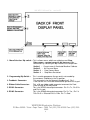
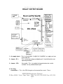
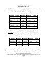
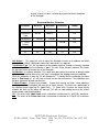
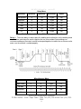
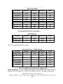
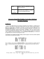
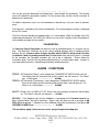
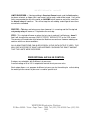
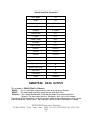
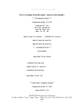
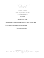
WK-MPS-16 SmartPak
version 52
SmartPak Welding Controller
WK-MPS-16 Constant Current
WESTKEN Electronics Division
Features
• Latest state of the art ATMEL 8 bit microprocessor technology
• Synchronous digital welding control allows absolute precision
• Up to16 programmers available
• Simple to use pushbutton keys
• All inputs optically isolated using +24V DC activation
• All outputs optically isolated
• Memory retention after power-down or mains failure
• Constant Current
• 4 lines x 20 characters alpha-numeric LCD display
• Front panel LED’s for all inputs, outputs & control operations
• Relay contacts for air valve switching – AC or DC.
• End of Sequence pulse (EOS) Relay Contacts – N/O or N/C
• Hi Lift Relay Contacts – AC or DC switching.
• 1st & 2nd Stage Initiation
• ½ Cycle Option Selectable
• Pulsation Option Selectable
• Meets European CE standard
• Seam Welding
• Alarm outputs
• Programmable Heat adjustment for tip wear
WESTKEN Electronics Division
PO Box 30205 - Tokai - Cape Town - 7966 Tel: (021) 705-6135/6 Fax: (021) 7055685
1
WK-MPS-16 SmartPak
•
•
•
•
•
version 52
Data output - RS232 /RS485/ Ethernet
Variable air pressure valve control with 5 recipes
Dipswitch selectable menus
Dual Gun (special output board)
Current readout in Standard Mode & Constant Current
(feedback coil required)
• Pgm sel – External selector or using the keypad
WESTKEN Electronics Division
PO Box 30205 - Tokai - Cape Town - 7966 Tel: (021) 705-6135/6 Fax: (021) 7055685
2
WK-MPS-16 SmartPak
version 52
SMARTPAK USER MANUAL
CONTENTS
Pg 1 ………………… Features Overview
Pg 3…………………. Contents
Pg 5…………………. Functional description of Front Panel
5.1 Power Led
5.2 Initiation Led
5.3 Hi Lift Input Led
5.4 Weld on/off Led
5.5 Hi Lift Relay Led
5.6 Air Valve Relay Led
5.7 End of Sequence Led
5.8 Weld Current Led
5.9 Pre-step Led
5.10 Step Led
5.11 Seam Motor Led
5.12 Program Number Leds
5.13 Data Comms Led
5.14 Scroll Up Menu Key
5.15 Scroll Down Menu key
5.16 Keypad Disable Led
5.17 (+) Increment Key
5.18 (-) Decrement Key
5.19 Thermostat 2 Led
5.20 Thermostat 1 Led
5.21 Alarm 2 Led
5.22 Alarm 1 Led
5.23 Constant Current Led
5.24 Lcd Display
Pg 8 ………………….Functional description of Reverse (Pcb) side of the
Front Panel
8.1
8.2
8.3
8.4
8.5
Dip switches for Menu activation
Programming Dip Switch (used by manufacturer)
Feedback Connector
Ribbon Cable Connector
RS232 Connector
WESTKEN Electronics Division
PO Box 30205 - Tokai - Cape Town - 7966 Tel: (021) 705-6135/6 Fax: (021) 7055685
3
WK-MPS-16 SmartPak version 52
8.6
RS485 Connector
Pg 9…………………. Functional description of the output relay board
9.1 Ac supply input
9.2 Jumper JP1
9.3 Jumper JP2
10.4 Scr firing connections
10.5 Jumper JP6
10.6 Jumper JP4
10.7 Jumper JP5
10.8 Solenoids connections
10.9 Air Pressure valve control
10.10 Output Relay Contacts
10.11 Signal Inputs
10.12 Ribbon Cable connector
Pg 12 .………………. Smartpak Menus
12.1 Weld Menu
12.2 Constant Current Menu
13.3 Restricted Machine Calibration
14.4 Delay Menu
14.5 Miscellaneous Menu
15.6 Communication Selection Menu
16.7 Air Pressure Menu
16.8 Reset Counters
16.9 Restricted Access Global Settings
17.10 Step Menu Restricted Global Settings
Pg 17 ………………….Push Buttons
17.1 Push Button Keys Functions
17.2 Changing Settings
Pg 18 ………………. Calibration
18.1 Calibration
Pg 18 ………………
Alarm Conditions
a) TSTAT1
b) TSTAT2
c) HI LIFT
d) NO COIL
e) NO CURRENT ALARM
f) LIMITS EXCEEDED
g) PRESTEP
h) STEP
Pg 19 …………………Proportional Air Valve Control
Pg 21 …………………Default Settings
Pg 22…………………Smartpak Data output (with examples)
WESTKEN Electronics Division
PO Box 30205 - Tokai - Cape Town - 7966 Tel: (021) 705-6135/6 Fax: (021) 7055685
4
WK-MPS-16 SmartPak
version 52
FRONT PANEL DISPLAY
1. Power Led (red) :- This shows when there is power +12v coming to the Display board.
2. Initiation(green) :- Start1 & Start2 . This is used to initiate welding . Start1 will enable the
airvalve while Start2 will complete the initiation process and allow the
welding to start.
Often both start1 & start2 and joined together (they are not used separately).
3. High Lift Input(green) :- This led will come on when the there is a +24v signal on the high lift
input.
4. Weld Output On/Off Control(green):- This is enabled/disabled by a+24v signal on the weld
on/off input. This will enable or disable the welding
output to Scr’s of the stack. Therefore one can go
through the welding sequence without any welding taking
place by disabling the Weld on/off output. This output
can also be controlled by using lcd display /keypad. This
control is in the weld menu.
5. High Lift Relay (green):This led will go on when the High Lift relay is turned on.
6. Air Valve Relay (red):This led is turned on when the Air valve relay is turned on.
WESTKEN Electronics Division
PO Box 30205 - Tokai - Cape Town - 7966 Tel: (021) 705-6135/6 Fax: (021) 7055685
5
WK-MPS-16 SmartPak version 52
This led comes on when the Eos relay is enabled.
This signifies the weld cycle is complete and that it is
now ready for another initiation.
8. Weld Current (red):This led shows the weld current intensity. The brighter
led is the greater the weld current.
9. Pre-Step (green):This led comes on when the pre-step relay is
turned on. This will happen when stepping is enabled in
the step menu. Stepping is used to counteract tip wear
which results in welding current reduction. On each step
the current is increased by the predetermined amount
selected in the menu by change. Pre step comes on one
weld cycle before the End of Step output.
This led comes on when the end of Step relay is turned
10. Step (End of Step)(red):on. This means that the tip needs replacing . Welding
can continue however the end of step relay can be used
to stop welding.
11. Seam Motor Relay (red):This comes on when seam welding is selected in the
menu and welding has been initiated at the same time as
the air valve. It is used to turn on the seam motor which
is used to advance the material being welded.
12. Program Number (in binery – red):- This is the program number which has been selected via
a thumbwheel switch or the PLC . The red leds show the
number in binary notation.
13. Data Comms Led (red):This led comes on to data comms output in progress.
This is the data output which can be selected in RS232
,RS485 or Ether net mode. The data gives a record of
the welding operation and can be used as a record of the
welds .
14. Scroll Up Key :This key is used to scroll up through the menu’s on the
Lcd screen.
7. End Of Sequence (Red):-
15. Scroll Down Key :-
This key is used to scroll down through the menu’s on
the Lcd screen.
16. Keypad Disable Led (red):-
This led comes on when the keypad has been disabled.
17. Plus Key (+):-
This key is used to increment values selected on the
Lcd screen.
This key is used to decrement value selected on the
Lcd screen.
18. Minus Key (-):-
19. Thermostat 2 (green):-
20. Thermostat 1 (green):-
This led comes on when the thermostat 2 input has been
enabled ie 0V is present at thermostat 2 input of the
output board.
This led comes on when the thermostat 1 input has been
WESTKEN Electronics Division
PO Box 30205 - Tokai - Cape Town - 7966 Tel: (021) 705-6135/6 Fax: (021) 7055685
6
WK-MPS-16 SmartPak version 52
enabled ie 0V is present at thermostat 1 input of the
output board.
21. Alarm 2 (red) :-
22. Alarm 1 (red) :-
23. Constant Current Led (green):24. LCD DISPLAY :-
The alarm 2 led comes on when the alarm 2 relay has
been turned on. Alarm conditions that would cause it to
come on are End of Step and Current out of limits (only
constant current.)
The alarm 1 led comes on when the alarm 1 relay has
been turned on. Alarm conditions that would cause it to
come on are High Lift not enabled , thermostat alarm
and current too low (only constant current).
This led is turned if constant current has been selected
for welding.
This is a four by 20 alpha numeric Lcd display
which also has backlighting.
BACK OF FRONT PANEL DISPLAY
WESTKEN Electronics Division
PO Box 30205 - Tokai - Cape Town - 7966 Tel: (021) 705-6135/6 Fax: (021) 7055685
7
WK-MPS-16 SmartPak
version 52
1. Menu Selection Dip switch :- This is allows menus which are not being used Step,
Data comms , constant current & Air pressure to be
deselected. By switching the dip switches to the on position.
Switch 1 :- Current menu & Restricted Machine Calibrate
Switch 2 :- Air Pressure Menu
Switch 3 :- Data Comms Menu
Switch 4 :- Step Menu Restricted
2. Programming Dip Switch :3. Feedback Connector:4. Ribbon Cable Connector:5. RS232 Connector:6. RS485 Connector:-
This is used to programme the cpu and is not needed by
the customer. Should be in the On position.
This connector is for the Rogowski feedback coil . Pin 1
is the hot wire Pin 2 must be connected to gnd and Pin3 is gnd .
This a 34 way ribbon cable connector to connect the Front
Panel Display to the relay board.
This is the RS232 data output connector . Pin 2 is Tx , Pin 3 Rx
and Pin 8 is gnd.
This is the RS485 data output connector. Pin 2 is Txa , Pin 2 is
TXb. Pin 5 is RXa and Pin 6 is RXb. Pin 7 is Gnd.
WESTKEN Electronics Division
PO Box 30205 - Tokai - Cape Town - 7966 Tel: (021) 705-6135/6 Fax: (021) 7055685
8
WK-MPS-16 SmartPak
version 52
RELAY OUTPUT BOARD
1. Ac supply input :- This is a 19v @10VA ,14v@8VA & 19v@30VA ac supply can from
220 or 380v AC.
2. Jumper JP1 :This is to connect analog and digital gnd. It should linked for most
operating conditions.
3. Jumper JP2:-
Key enable . This is to enable the keypad and can be used to
override the key enable/disable input.
4. Scr firing
connections :- This is the SCR firing pulses that control the current . These
WESTKEN Electronics Division
PO Box 30205 - Tokai - Cape Town - 7966 Tel: (021) 705-6135/6 Fax: (021) 7055685
9
WK-MPS-16 SmartPak version 52
pins are for the gate and cathode of scr1 & scr2. A mov or transorb
can be fitted to provide extra protection for the SCR’s .
5. Jumper JP6 :- This is used to connect the 3 diodes on the Hi Lift , Seam & Air valve.
For back emf protection generated by the solenoids.( Not connected
for AC solenoids)
Connected when using DC solenoids.
6. Jumper JP4 :- This the +24v for DC solenoids which are using the relay board’s
internal supply. (this jumper is not connected when using
ac solenoids or an external dc supply)
7. Jumper JP5 :- This the internal 0V for DC solenoids which are using the relay
board’s internal supply. (this jumper is not connected when using
ac solenoids or an external dc supply)
8. Solenoids
Connection:- These are the connections for the Seam,Hi Lift & Air valve solenoids
9. Air Pressure
valve control :- This is the variable air pressure control voltage ouput.
1. This is connected the valve control circuit as well as gnd
10. Output Relay
Contacts :-
These contacts are for EOS,ALARM1,ALARM2,PRE_STEP
1. & End of Step. The N/O contact and the Com are available.
11. Signal Inputs :- These are signal inputs +24v is on and 0v is off. (except for
1. thermostats which reversed). The signal +24v is available on the
connector as well as the Input gnd. These
are isolated from the
2. solenoid 24v supply for noise protection.
12. Ribbon Cable
Connector :- This is a 34 way ribbon cable connector used to connect the display
panel to the relay board.
WESTKEN Electronics Division
PO Box 30205 - Tokai - Cape Town - 7966 Tel: (021) 705-6135/6 Fax: (021) 7055685
10
WK-MPS-16 SmartPak
version 52
SmartPak Menus
The WK-MPS-16 welding controller offers up to 16 different programs and is designed for use
with single-stage or dual-stage initiated projection & spot welding stations.
Function: MWK-MPS-16 (Projection/Spot)
Weld Menu
Parameter
Minimum
Maximum
Resolution
Global
Weld 1
0
99
1 Cycle
No
Weld 2
0
99
1 Cycle
No
Weld 3
0
99
1 Cycle
No
% Heat 1
10%
99%
1%
No
% Heat 2
10%
99%
1%
No
% Heat 3
10%
99%
1%
No
Weld On/Off
-
-
On/Off
Yes
Default setting for Weld On/Off is on
Three weld procedures are possible at the %heat can be set from 10% to 99% When the
number of weld cycles is 0 they will not be used. Ie for Weld2 & Weld3.
Weld On/Off: This a control available as an external control or internal(keypad) to turn
the welding on or off. This will not stop the timer going through the complete cycle the
only difference being that there will be no welding current.
Constant Current
Parameter
Minimum
Maximum
Resolution
Global
Constant Current
-
-
On/Off
No
Target Current 1
1 KVA
60 KVA
100 VA
No
Target Current 2
1 KVA
60 KVA
100 VA
No
Target Current 3
1 KVA
60 KVA
100 VA
No
DIP SWITCH 1(enable menu)
Constant Current :- This is a prime feature of the timer and will using a feedback coil to
measure the current will keep the current constant to a pre-selected
target . Each welding procedure has a separate target setting.
Constant current needs to be selected for a particular program
WESTKEN Electronics Division
PO Box 30205 - Tokai - Cape Town - 7966 Tel: (021) 705-6135/6 Fax: (021) 7055685
11
WK-MPS-16 SmartPak version 52
and will show it has been selected by a green led on the faceplate
of the Smartpak.
Restricted Machine Calibration
Parameter
Minimum
Maximum
Resolution
Global
Coil Output
80mV
220mV
1mV
Yes
Transformer
Type
50KVA
400KVA
-
Yes
Cal Machine
1 - Yes/No
2 - Yes/No
-
Yes
Yes/No
Yes
C
Limits
enable
U%
4%
25%
1%
Yes
L%
4%
25%
1%
Yes
DIP SWITCH 1 (enable menu)
Coil Output : This allows the user to adjust the Smartpak to cater for a feedback coil which
does not have 150mV /1000 amps output and it more or less as required.
Transformer Type: This the transformer of the welding machine. It needs to correctly selected
and this will occur when the calibration is done. This can still be altered if required. This affects
the constant current characteristics of the Smartpak..
Cal Machine : or calibrate machine. This needs to be done when the machine is being installed
and should not need be done unless the timer is changed or the welding machine is modified.
When the calibration is done the “N” will change to a “Y” showing that the calibration has been
done. In Dual mode a 1 & 2 will show as there are now two transformers. The calibration must
be done separately for both transformers .
C Limits Enable : (Current Limits enable) Current limits can be set which - when welding in
constant current are exceeded will bring up an Alarm (alarm2). The limits are a percentage of
the welding current target eg 5% (upper limit ) 7% (lower limit). So when the actual current
exceeds the limits set the alarm will come on. This will not stop welding how ever the alarm2
output can be used disable welding.
U% : This refers to the Upper Limit and is set between a minimum of 4% up till 25% maximum.
L% : This refers to the Lower Limit and is set between a minimum of 4% up till 25% maximum.
WESTKEN Electronics Division
PO Box 30205 - Tokai - Cape Town - 7966 Tel: (021) 705-6135/6 Fax: (021) 7055685
12
WK-MPS-16 SmartPak
Delay Menu
version 52
Parameter
Minimum
Maximum
Resolution
Global
Pre-squeeze
0
99
1 Cycle
No
Squeeze
0
99
1 Cycle
No
Cool
0
99
1 Cycle
No
Cool2
0
99
1 Cycle
No
Hold
0
99
1 Cycle
No
Off
0
99
1 Cycle
No
NB Repeat is enabled when Off is set too greater than 0
Delays :- These are delays used to space the welding and to allow time for the welding head
to come down and clamp the metals together that are to be welded. Spot welding uses
resistance welding so the metals need to be clamped together to reduce the resistance and to
make sure the material is welded properly.
Miscellaneous Menu
Parameter
Minimum
Maximum
Resolution
Global
Pgm Select
0
16
1 pgm
Yes
Upslope
1
10
1
No
Pulsations
1
99
1 pulse
No
W
1
2
1
No
WESTKEN Electronics Division
PO Box 30205 - Tokai - Cape Town - 7966 Tel: (021) 705-6135/6 Fax: (021) 7055685
13
WK-MPS-16 SmartPak
seam
version 52
On/Off
Yes
Pgm select: This is used to select the external pgm select - which normally a thumbwheel
selector or can be controlled by the PLC. – or internal pgm select this is the done via the
keypad .
Upslope : This slopes the current from 0 amps up to the welding current selected. This is will be
a longer or shorter slope depending on how many upslope cycles are selected.
Pulsations: Is only for Weld 2 or Weld1 depending on what has been selected in the misc menu.The
number of pulsations is selectable between 1 and 99. The pulsation
Cycle consists of Weld1/2 & Cool1/2 and will loop around these two until the pulsations are
complete. It will then proceed with the rest of the selected cycle.
Weld procedure Select
This is to select whether the pulsations will be on weld procedure 1 or weld procedure 2 . Weld
procedure 3 is not used.
Seam: This is for seam welding and will weld on the first weld procedure only. It is activated
when start1 and start2 are enabled and will continue welding until start1 or start2 are turned
off. The seam motor output will come on at the same time as the air valve. When start1 or
start2 are turned off the smartpak turns off the seam motor and air valve and exits the weld
routine . It does an EOS and is then ready to start welding again.
Comms Selection Menu
Parameter
Minimum
Maximum
Resolution
Global
Data Output
-
-
On/Off
Yes
RS232/RS485
-
-
select
Yes
DIPSWITCH 3 (enable menu)
Data Output : The data output provides real time information about the weld and can viewed
via RS232 or RS485 or Ethernet.
RS232/RS485 : This is select either RS232 or RS485 comms
WESTKEN Electronics Division
PO Box 30205 - Tokai - Cape Town - 7966 Tel: (021) 705-6135/6 Fax: (021) 7055685
14
WK-MPS-16 SmartPak version 52
Air Pressure Menu
Parameter
Minimum
Maximum
Resolution
Global
REF PRESS
0 bar
10 bar
0.1 bar
Yes
RECIPES
0
5
1
No
Air Press P1
0 bar
10 bar
0.1 bar
No
Air Press P2
0 bar
10 bar
0.1 bar
No
Air Press P3
0 bar
10 bar
0.1 bar
No
Air Press P4
0 bar
10 bar
0.1 bar
No
Air Press P5
0 bar
10 bar
0.1 bar
No
DIPSWITCH 2 (enable menu)
See Proportional Air Valve control Pg 19
Reset Counters
Parameter
Minimum
Maximum
Resolution
Global
Machine Count
0
999
Reset
Yes
Step Count
0
20
Reset
Yes
This is for resetting the counters to zero.
Restricted Access – Global Settings
Parameter
Minimum
Maximum
Resolution
Global
Power Factor
0
0.99
0.01
Yes
Ext Pgm Select
-
-
On/Off
Yes
Hi Latch
-
-
On/Off
Yes
Default Settings
-
-
On/Off
Yes
Dual Mode
-
-
On/Off
Yes
½ Cycles
-
-
On/Off
No
This is intended for the technician or engineer only
Power Factor or PF :- This is a global setting which in reality advances or retards the firing
angle of the SCR firing pulses. Ie increases or reduces the heat. This global setting allows
WESTKEN Electronics Division
PO Box 30205 - Tokai - Cape Town - 7966 Tel: (021) 705-6135/6 Fax: (021) 7055685
15
WK-MPS-16 SmartPak version 52
correction needed because of the transformer (each machine needs a slightly different
adjustment.
Ext Pgm Select :- This allows program selection either via the external program switch or by
the internal keypad.
Hi Latch :This to enable Hi Lift Latch mode. This enable the hi lift to latched on
with a hi lift input pulse . The next pulse will unlatch it.
Default Settings :- When the plus key is pressed the default settings is enabled and when
The plus key is pressed again the default nsettings will be loaded into
all the values.
Dual Mode :Dual Mode allows the timer
Step Menu Restricted
Global Settings
Parameter
Minimum
Maximum
Resolution
Global
No of Steps
0
20
1
Yes
Counts /Step
0
999
1
Yes
% Heat Change
0
10
1
Yes
DIPSWITCH 4(enable menu)
This is intended for the technician or engineer only
The above parameters are all fully programmable via the push button front panel keys and
displayed in English on the 20 characters x 4-line LCD display.
Other languages can be accommodated.
NOTE : 4 dip switches are available on the control pcb which can disable menus not
being used.
Push Button Keys Functions
Key
Function
FORWARD
^
Scrolls forward through the Menus &
Parameter Settings
BACKWARD v
Scrolls backward through the Menus
Parameter Settings
&
INCR
+
Increments the selected parameter setting
DECR
-
Decrements the selected parameter setting
WESTKEN Electronics Division
PO Box 30205 - Tokai - Cape Town - 7966 Tel: (021) 705-6135/6 Fax: (021) 7055685
16
WK-MPS-16 SmartPak
INCR
+
FORWARD ^
&
version 52
Used to select the Adjustment menu to
change parameters
Both Buttons pressed together - to Access
The Restricted Global parameters
BACKWARD v
Changing SmartPak Welding Controllers Settings
On Each Program
On Power Up
The message SMARTPAK will be displayed. Provided the KEY ENABLE is enabled and the
controller is not welding the Backward and Forward keys will allow scrolling through the Menus.
When the required Menu is reached use the Incr + to select the menu for adjustment. The
Forward and Backward keys are then used to scroll through the parameters. The screen cursor
will indicate the parameter selected and the Incr + and Decr – keys can then be used to
increment or decrement the parameter setting. . Once the new value is seen on LCD screen the
value is updated and will be remembered. Use the Forward or Backward keys to scroll out of
the adjustment menu and return to the previous menu.
The following is an example of a typical welding controller program and what could be expected
to be seen on the Liquid Crystal Display: -
PGM
[02] WELD MENU On
WELD1
10 HEAT1 29%
WELD2
0 HEAT2 18%
WELD3
0 HEAT3 12%
Press the Incr + key to enter the Adjustment Menu. You have about four seconds once the
Menu is selected to proceed to the adjustment menu. The adjustment menu will look similar to
This: ADJUST : Weld/ON = on
WELD1 10 HEAT1 29%
WELD2 0
HEAT2 18%
WELD3 0 HEAT3
12%
WESTKEN Electronics Division
PO Box 30205 - Tokai - Cape Town - 7966 Tel: (021) 705-6135/6 Fax: (021) 7055685
17
WK-MPS-16 SmartPak version 52
You can by using the backward and forward keys scroll through the parameters. The flashing
cursor will indicate the parameter selected. The incr or decr keys can be used to increment or
decrement the parameter.
To exit the adjustment menu use the backward or forward keys until you return to previous
menu.
The Pgm No is selected by the external thumbwheel. The current program number is displayed
on the LCD screen.
The Hi-Lift input will disable the welding output if it is not enabled - (Both Key Enable and Hi Lift
need to be connected to +24V REG if the features are not used. A jumper on the Relay board is
also available to jumper the key enable.)
CALIBRATION
For Constant Current Operation the weld unit must be calibrated before it is used for the first
time. The Weld Unit should be set up for normal welding operation with no welding material
between the bits. However where a larger machine( above 15KVA is being used it is better
to calibrate it with the welding material that is to be used. When constant current is selected
on the controller the Smartpak controller will ask to do a calibration . Please follow the
instructions given. Once the unit has been calibrated there is no need to do it again except in a
very large machine where is a big difference between welding materials.
ALARM
CONDITIONS
TSTAT1: - IF Thermostat (Stack) is over temperature THERMOSTAT ERROR will be seen on
The display and the thermostat led and the Alarm1 led will come on. The Alarm1
has a relay output ………………… :- ALARM1
TSTAT2: - IF Thermostat (Transformer) is over temperature THERMOSTAT ERROR will be
Seen on the display and the thermostat led and the Alarm1 led will come on. The
Alarm1 has a relay output …………. :- ALARM1
HI LIFT: - If High Lift is off HIGH LIFT OFF will be seen on the display and Alarm1 led will come
on. The Alarm1 relay will also come on. :- ALARM1
NO COIL: - If no Rogowski coil (current feedback) is connected and if Constant current has
been selected Alarm1 led will be activated – Alarm1 relay will come on and a message of NO
COIL will be displayed – if it detects less than 400Amps input after 3 weld cycles it will give a NO
CURRENT ALARM Error. ……………………….. :- ALARM1
This would also apply if there was no current going through the welding tips.
WESTKEN Electronics Division
PO Box 30205 - Tokai - Cape Town - 7966 Tel: (021) 705-6135/6 Fax: (021) 7055685
18
WK-MPS-16 SmartPak
version 52
LIMITS EXCEEDED :- If during welding in Constant Current mode and the limits options
has been selected an Upper Limit and Lower Limit for each weld will be tested . If any of the
limits are exceeded for any of the welds an ALARM2 led will come on and at the same time
the Alarm2 relay will come on. This will not stop the unit welding and will go off once there
are no limits exceeded.
PRESTEP: - This does not bring up an alarm however it is a warning and the Prestep led
and prestep relay will come on 1 step before the end step.
STEP: - This step led will come on when the last step is reached. It will bring on alarm 2
And it will also print the message “END OF STEPS REPLACE TIP” on the LCD screen.
The counters will need to be reset before the Machine can continue. However welding can
continue with these alarm conditions.
ALL ALARM CONDITIONS CAN ALSO BE SEEN IN THE DATA OUTPUT IF USED. THIS
WILL GIVE A RECORD OF WHAT HAS HAPPENED SHOWING THE EXACT AMOUNT
THAT THE LIMITS WERE EXCEEDED .
PROPORTIONAL AIR VALVE CONTROL
5 recipes are selectable with 5 different air pressures .
A control voltage of 0 to 10V is outputted to control the air pressure valve.
Each recipe allows a set program of different air pressures for the weld cycle so that during
the weld cycle the correct air pressure is used for specific task.
WESTKEN Electronics Division
PO Box 30205 - Tokai - Cape Town - 7966 Tel: (021) 705-6135/6 Fax: (021) 7055685
19
WK-MPS-16 SmartPak
version 52
SMARTPAK AIR PRESSURE PROGRAMS
NO VARIABLE AIR PRESSURE
PRESS PGM 0
PRESS PGM 1
PRESS PGM 2
PRESS PGM 3
PRESS PGM 4
PRESS PGM 5
P1
PSQ
P1
PSQ
P1
PSQ
P1
PSQ
P1
PSQ
PSG
P3
Off
P2
Weld
SQ
Hold
P3
P2
SQ
P2
SQ
Weld
Hold
Off
P3
Weld
P4
Hold
Off
P3
P2
SQ
Hold
Weld
P3
P2
SQ
Weld
P4
Hold
P4
Off
P5
Off
eg
PGM(0) AIR PRESSURE
Press Pgm 1 REF 10v
AIR PR: P1 2.2 P2 2.7
P3 3.5 P4 5.5 P5 6.8
WESTKEN Electronics Division
PO Box 30205 - Tokai - Cape Town - 7966 Tel: (021) 705-6135/6 Fax: (021) 7055685
20
WK-MPS-16 SmartPak
version 52
Default Values
The default values are loaded in all the 16 programs and will stay at theses value until they have
been changed. Once they have been altered they will have the new value.
Default SmartPak Parameters
Function
Prom/Spot
Pre-Squeeze
25 Cycles
Squeeze
25 Cycles
Weld 1
15 Cycles
% Heat 1
20%
Cool
0 Cycles
Weld 2
0 Cycles
% Heat 2
10%
Cool2
0 Cycles
Weld 3
0 Cycles
Hold
10 Cycles
% Heat 3
10%
Off
00 Cycles
WELD/ON
ON
WESTKEN Electronics Division
PO Box 30205 - Tokai - Cape Town - 7966 Tel: (021) 705-6135/6 Fax: (021) 7055685
21
WK-MPS-16 SmartPak version 52
Default SmartPak Parameters
Dual Mode
Off
Seam
Off
Coil Output
150mV
Machine Calibration
No
Upslope
0 Cycles
Current Limit
5%
½ Cycles
OFF
Power Factor
68%
Pulsations
01
High Lift Latch
OFF
Current1
3.0 KVA
Current2
2.0 KVA
Current3
2.0 KVA
Steps
0
Counts per Step
0
% Heat Change Correction
0
Machine Cycle count
0
Step Count
0
Data Output
OFF
RS232
Selected
SMARTPAK DATA OUTPUT
This available in RS232 ,RS485 & Ethernet.
RS232 :- This is a serial data stream and can work up to a distance 15meters
RS485 :- This a balanced serial data stream and can work up to 2 km.
Ethernet :- This a Local Area Network (LAN) and will contect to a standard industrial
Network. The data output from the Smartpak is then sent via this network
The purpose of the data output is to give a real time record of the welding process which can be
used for monitoring , quality control , tip & tool wear and fault analysis by engineer in charge.
WESTKEN Electronics Division
PO Box 30205 - Tokai - Cape Town - 7966 Tel: (021) 705-6135/6 Fax: (021) 7055685
22
WK-MPS-16 SmartPak
version 52
This is an example of the Data output feature of the Smartpak :******STANDARD MODE******
Programme No 00 P.F. 0.82
Weld ON/OFF : ON
Pre-sq 25 squeeze 25
Cool 00 Cool2 00
Hold 10 Off 00
Weld 1 Cycles 16 Heat 53%
CURRENT W1: 04.6 KA
Weld 2 Cycles 00 Heat 10%
Weld 3 Cycles 00 Heat 10%
**** ALARMS STATUS ****
NO ALARMS
MACHINE CYCLE 01384
CURRENT W2: N0.3 KA
Weld 3 Cycles 16 Heat 24%
CURRENT W3: W4.0 KA
MACHINE CYCLE 132
***CONSTANT CURRENT MODE**
Programme No 00 P.F. 0.82
Weld ON/OFF : ON
WESTKEN Electronics Division
PO Box 30205 - Tokai - Cape Town - 7966 Tel: (021) 705-6135/6 Fax: (021) 7055685
23
WK-MPS-16 SmartPak version 52
Pre-sq 25 squeeze 25
Cool 00 Cool2 00
Hold 10 Off 00
CURRENT
TARGET
Weld 1: 16 cycles 04.0 KA
04.0 KA
**** ALARMS STATUS ****
NO ALARMS
MACHINE CYCLE 01401
The rated voltages for the air valve solenoids are 24V dc - 1 amp or 110 V ac - 1 amp.
All other connections are provided on the Relay output board.
See customer connections.
WESTKEN Electronics Division
PO Box 30205 - Tokai - Cape Town - 7966 Tel: (021) 705-6135/6 Fax: (021) 7055685
24