1
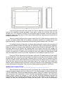
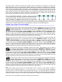
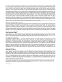
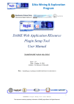
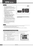
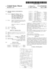
eSherlock
1800 Tx8 USERS GUIDE
Software
19th December 2014, version 1.1r04
Home Automation System
with GSM Alarm
and Additional Features
eSherlock 1800 Tx8 includes a full Home Automation and GSM alarm system,
based on DOLLx8 Embedded Network communications. The LCD display provides as
many as 20 characters in two lines, with large 5mm tall characters, and blue backlit.
eSens Me2 front panel consists of capacitive touch panel with LED backlit buttons
that also make it visible in total darkness. The front panel has three group of touch buttons,
EMERGENCY, KEYPAD and FUNCTION KEYS. In addition, there is Enter and Cancel
buttons, as well as Back and Forward. There is also three green LED's for port status,
alarm, and GSM call indication. Finally there is a microphone and speaker output for GSM
calls.
Most
products delivered from MISOLIMA are based on DOLLx8
(Digital One Line Link) Embedded Network communication, allowing
eSherlock and other devices to expand to LED light control, solar cell
system, 4x4 channel audio system, GPS, relay and I/O port control, to
manage in- and outdoor lights, music, alarm system, watering systems,
garage port or gate opener, and much more. The built in DOLLx8 functions are text based,
fully programmable, and can be used and managed directly via USB, GSM, or via Wi-Fi,
using the MISOLIMA's eMaster Wifilised device. In one DOLLx8 Network Bus system, only
one Wi-Fi connection is needed.
For easy installation, the DOLLx8 Network data bus uses standard 8-pin UTP cable
with RJ-45 connectors, the same cable used in PC networks or between Internet router
and PC. This makes set-up and installation of MISOLIMA's DOLLx8 Embedded Network
really fast, easy, and low-cost, compared with other systems. The DOLLx8 on eSherlock is
provided with a 8-pin Single In Line (SIL) RJ-45 connector cable. This connector cable is
pin compatible with other DOLLx8 products and devices. To use more than one DOLLx8
device, a DOLLx8 T-splitter is needed.
Each DOLLx8 device has a unique Device ID named DID, and once each
device connected, has its own unique DID, and the UTP network cable
connected to MISOLIMA's eMaster USB or Wifilised, a DOLLx8 two-way data
communication is established between the PC and the DOLLx8 Network Bus.
For the use with Android, Apple, BlackBerry, or Microsoft-based smart phones
or tablets/pads, a typical set-up would be to use eMaster Wifilised together with a Wi-Fi
access point. eSherlock needs software or GSM phone to set-up the system, even though
some of the functions can also be set-up from the eSens Me2 touch panel.
FEATURES __________________________ APPLICATIONS ___________
20x2 characters LCD display with blue backlit
Home Automation for home and office
Integrated replaceable SAGEM GSM module
Access and message control for rental office
Integrated replaceable Micro Controller Unit (MCU)
Retirement homes
Integrated audio amplifier for GSM
Condos
SpyCall function with listening-only mode
Doors, garage door and gate control
Direct emergency call to police, fire, ambulance and owner.
LED light control
4 direct and 12 function keys
Vehicle alarm (without eSens Me2)
1x DC relay, maximum 30V 3A and 1x AC relay 110/220V - 5A
Marine boat alarm
DOLLx8 Embedded Networking for Home Automation and GSM alarm
Electronics control and measurements
Home Armed alarm system features
Multi-purpose access control
Thank you for choosing and/or considering MISOLIMA Home Automation and Security
System. This User's Manual will explain for you, your family members and/or
employees and staff the basics of how to use the eSherlock 1800 Tx8, eSherlock MINI
and Wifilised. For more detailed programming information, please read the “DOLLx8
MADE LIVE WITH eSherlock” hard cover book from MISOLIMA Publishing. (ISBN
ISBN 978-616-305334-3) For additional information on other DOLLx8 products from
MISOLIMA, see their respective User Guides, as they will provide further
documentation and information as needed. This User's Manual will ensure that the
eSherlock system will provide years of reliable operation.
eSENS ME2 KEYPAD __________________________________________
The eSens Me2 front panel is based on
selective capacitive touch technology, where
there is no moving parts or switches to allow key
functions to work. Each set of buttons has LED
backlit given in Red, Green and Orange colours.
The LCD display has light characters on blue
background, while I/O port, Alarm, Charging and
Telephone indication LEDs are green.
The LCD and LEDs will automatically close after
15 seconds after last touched, but they can also
stay on all the time by using the *500# LED function.
THE KEYS USED _____________________________________________
This key is the emergency key for calling the stored Police Emergency Number
This key is the emergency key for calling the stored Fire Emergency Number
This key is the emergency key for calling the stored Medical Emergency Number
This key is the emergency key for calling the stored Owners Emergency Number
0-9
These numeric keys are used to enter passwords, numeric functions or data.
*
Always begin with this * for entering stored functions
#
Always end a 3 digit stored with #
Always confirm a function with Enter or Confirm
Use this key to cancel any operation at any time
F1 - F4 This is user defined function keys where user can save two DOLLx8 functions
behind each function key. The functions are then toggled for every 2 nd press on the key.
This is the back key to correct numbers entered or move back one step on the LCD
display
This key is used to enter hexadecimal numbers from A-F
THE LEDs USED ______________________________________________
There is 6 LEDs shown on the eSherlock 1800 Tx8 eSens Me2 touch panel, 3 for
Alarm Switch or I/O ports, shown as ASW1, ASW2 and ASW3 on connector K14, and 3 for
the indication of Buzzer, Charging from external power source (taken from pin CHARGING
on K14) and Phone which is also indication of armed alarm if blinking.
The three green I/O port LED's next to the I/O port sign, are indication to show bit
status of port number 0 and bit 0 to 2. If this is connected to magnetic switch or
PIR (infra red moving censor), the LED will also show port status even if the alarm
is disarmed.
The alarm indicator LED will always follow the buzzer sound, and the main
purpose is to have a visual alarm indication for deaf users.
The charge battery indicator is operated from outside source like MISOLIMA
eSolar Cell 2.5 to indicate when the solar cell battery is charging. The signal is
taken from K7 “CHARGE” pin 2 eSolar Cell 2.5. The indications are; OFF=Fully
Charged, ON=Charging and BLINK=Battery Empty. If no solar cell data is connected, the
LED can also be controlled and managed by DOLLx8 data bus commands to indicate
user specific functions.
The LED for phone LED will indicate when there is an incoming call. It is ON
whenever the calling tone is active. If SMS is received to the unit, the SMS text will
be displayed on the LCD display until the someone click Cancel or a new SMS is
received. When the alarm is armed, this Phone LED will blink until the alarm is disarmed,
and the LED is then off. If a phone call or SMS is received during armed alarm, the LED
will continue to blink. If Home Armed function is active, the phone LED will blink in the
same way as the fully armed alarm would do.
USE OF POWER ______________________________________________
The eSherlock does not use "Power ON" indication, as most of the time, the power
consumption on stand-by without LED or LCD on is 70mA. When active with LCD and LED
on, the power consumption is between 90-100mA. If connected to MISOLIMA eSolar Cell
2.5 standard battery, the stand-by time is 35 hours with option of 57h and 85h (requires
change of battery capacity). Please note that this does not include power for 12Vdc used
for LED lights or 12Vdc alarm horn. The eGSM mobile phone unit has its own 500mA LiIon battery. This battery is charged from solar cell or main power source.
If eSolar Cell with its battery is used as battery backup for eSherlock 1800 Tx8 and
eSherlock Mini, then the battery is charged during daytime via solar cell technologies, and
via 110/220 transformer from the mains during night time or when the battery is poorly
charged due to rain or dark winter days.
For power cut, the alarm system will still work uninterrupted from its eSolar Cell 2.5
battery power, which is optional and not included in the total eSherlock package.
The alarm is also suitable at holiday homes in the mountains or at sea, where there
might be no electricity available. The charge is then done solely via solar cell technologies.
INSTALLATION OF eSherlock 1800 Tx8 ___________________________
Remove the MISOLIMA eSherlock 1800 Tx8
from its box. Remove the protecting
plastic and carefully remove the eSens Me2 front panel by lifting it off the backside PCB
with LCD, eGSM and ePAT MCU module. Now be careful not to scratch the LCD module
with any sharp objects.
Insert a new GSM SIM-card as shown on the right image into the
SIM socket of the eGSM module. Make sure there SIM is activated and
that there is money on the card. The provided GSM antenna is for now
not needed, as this is the last thing to be fastened before the eSens
Me2 front panel is inserted and fastened onto the PVC frame.
eSherlock comes with PVC frame for wall mounting, secured with four screws.
Make sure that eSherlock is securely fastened to the wall, and that the Alarm Switch 4
(ASW4) at the back is pushed into the wall surface in closed position. Conduit entrance
are provided from the back, but could also be done via knock-outs on top or bottom of the
PVC frame. If eSherlock is mounted without the PVC frame, enough space for the back
Printed Circuit Board (PCB) has to be provided. The same PCB have also two holes for
fastening to a standard double wall box used for electricity power outlets and light
switches. If eSherlock is mounted in the wall instead of using the provided PVC frame, the
visible part of the unit will then be only 1.6 mm. With the PVC frame it will be 30 mm.
IMPORTANT! Make sure that eSherlock is not mounted is direct sunlight, as the
temperature for the LCD display could be higher than the maximum operational
temperature. If eSherlock is used in vehicles, use the eSherlock Mini version that comes
without LCD display and eSens Me2 front panel.
Front and right hand side view of the PVC frame. Mark the 4 screw holes and drill
hole for the fastening screws provided. If the wall is made out of wood, just use the
screws, but if it is concrete or bricks, use the plastic plugs provided. Once the holes are
prepared, make sure they are in 100% water before drilling or fastening the frame with its
backside electronics.
After the cables are fixed and in place, fasten the PVC frame securely with the four
screws, and place eSens Me2 on its position, and press carefully so it slides into the two
black connectors. Fasten the front panel with the four small screws to the PVC frame.
For surface mount of eSherlock, the beck-side electronics needs to be mounted into
a connector standard double wall box used for electricity power outlets and light switches.
Make sure there is enough space behind and around the backside eSherlock PCB. The
first step would be to remove the eSence Me2 front panel, and the LCD display by
unscrew the four nuts holding it. The PCB has two 3mm holes that should fit the fastening
holes on the wall box. If a wall box out of metal is used, then make sure that the the metal
does not make short circuit on the PCB. The best is to use wall box made out of PVC.
Once the PCB is fastened to the wall box, insert the LCD display and the front panel
to ensure that the front panel will be surface mounted into the wall, and that there is space
to fasten the four screws into the wall. The best way to do this if this is a concrete or brick
wall, is to make a wood frame and let the four holes in the front panel fit so it is possible to
screw the four screws into the wood. Note that if this is for a brick wall, then make sure
that the wall is plastered before inserted, or that the thickness of the plastering is included
in the calculations of the depth. The inner wood frame opening should be 122x73mm.
WIRING AND CONNECTIONS ___________________________________
The first thing to do before wiring and connections, are to ensure that eSherlock has
a good and secure power source of minimum 2A. It is recommended to use the eSolar Cell
2.5 from MISOLIMA, as this provides automatic power charge for battery from both solar
cells and power from transformer. eSolar Cell does automatically charge a 12V motor bike
battery directly, where the charger in it self has also DOLLx8 Embedded Network for
measurements and charging managements. During the day, eSolar Cell will charge the
battery via solar cell, and during the evening and the night, it will use the stored battery
power. If the battery should run out of power, due to rainy or overcast days, the charging
device would automatically switch over to the mains, as main power source inlet for the
charging circuit.
The left side image shows eSherlock seen
from the back side. For speaker volume, a
potentiometer is provided at VR3. To adjust
the volume, insert a SIM card, the GSM
antenna, and call the phone number. To
answer the phone, eSens Me2 front panel
must be inserted, and Confirm button
pressed. While speaking on the phone, adjust
the volume to preferred volume level. On
eSherlock MINI, the phone can be answered by sending an E with the @SK command, or
a C to cancel the call.
VR1 and VR2 is to adjust the text brightness and the blue backlit.
PIN
Signal
Description
Usage
1
ASW0
Alarm switch or I/O port
Connects to magnetic switch, PIR, sensor or used for TTL I/O
Wire colour
YELLOW
2
ASW1
Alarm switch or I/O port
Connects to magnetic switch, PIR, sensor or used for TTL I/O
ORANGE
3
ASW2
Alarm switch or I/O port
Connects to magnetic switch, PIR, sensor or used for TTL I/O
4
ADC0
10-bit Analogue to Digital Converter
Measurements of temperature
BROWN
5
ADC1
10-bit Analogue to Digital Converter
Measurements of light LUX values
BLACK
6
ADC2
10-bit Analogue to Digital Converter
General purpose ADC channel
WHITE
7
VBAT(ADC3)
External voltage measurement
Battery voltage measurement from i.e. eSolar Cell 2.5
8
Charge
External charge indication
External battery charging status
9
+5V
5Vdc power IN or OUT
Power IN from i.e. USB or OUT to other 5Vdc devices.
10
GND
System ground
-
RED
GRAY
PURPLE
BLUE
GREEN
Table II. - Cable connections for K14
Please note that the pin-connector in Table III. is to be connected directly to DOLLx8 bus
via the MISOLIMA SIL10CON connector cable with 8-pin RJ-45 connector.
PIN
Signal
Description
Usage
1
DAT-
Data active low
Data between Master and Slave - in full duplex
Wire colour
GRAY
2
DAT+
Data active high
Data between Master and Slave - in full duplex
PURPLE
3
BSEL-
Bus Select active low
Output from DOLLx8 Master in full duplex
4
+12VdcIN
Power in
+12Vdc taken from power source (8-28Vdc)
5
+5Vdc IN
Power in (USB)
+5Vdc taken from the USB or DOLLx8 bus
YELLOW
6
BSEL+
Bus Select active high
Output from DOLLx8 Master in full duplex
ORANGE
7
CLK
Signal Clock
Serial clock with output from DOLLx8 eMaster
8
GND
Signal Ground
Signal and system ground
BLUE
GREEN
RED
BROWN
TABEL III. - Cable connections for K2
eSherlock has two integrated relays
for control of alarm horn, LED lights,
or any devices uses that 12/24 Vdc
110/220Vac (L=Brown N=Blue) with the
maximum of 5A. Both relays has
REST and SET position, where the
REST is the resting state of the relay,
and SET is when the relay is set or
equal to high output to the transistor
controlling the relay. Both relay can be connected to any devices, as long as the maximum voltage and
ampere ratings are not exceeded. As we can see from the previous diagram, the voltage input for REL1
could also be taken from the Vin connector K15 on eSherlock. This is done by shortening 2-3 on J4. If 1-2 on
J4 is shortened, the relay will use voltage input from K3 "DC-IN" and COM (+) and GND. In the same time,
REL2 could also have the same power source if it is i.e. connected to LED lights, or any other electronics
that require 12Vdc or equal to the input power voltage. If this is connected to a 12V battery in a vehicle, the
power could be as high as 17 volt from the dynamo, which is not a problem for eSherlock as it contains a
SMPS with maximum input voltage of 30Vdc, but must be taken into account for 12V devices. REL1 has also
option to draw coil power from the Li-Ion battery or from the 5V DC-DC converter. If the jumpers on J2 is set
to 1-2, then the coil power will use power from the Li-Ion GSM battery. If connected to pin 2-3, then the coil
power is taken from the 5V DC-DC power supply. If the 5V DC-DC power supply is used, the relay will not
work in the case of power-cut. If REL1 coil power is connected to the Li-Ion battery, the stand-by time for
microcontroller and GSM module will be shorten if the main power is cut.
The K2 MISOLIMA SIL08CON connector cable has RJ-45
connector that connects directly to the DOLLx8 Embedded Network
via UTP network cable. If several devices are used, then the UTP
cable connecting to eSherlock, must connect to to the centre
connector on DOLLx8 T-Splitter as shown on the right image. A to D is eSherlock devices connected to the
centre connector on DOLLx8 T-Splitter. Any of the eSherlock devices can be MASTER device, but if not, the
eMaster USB, or eMaster Wifilised must act as MASTER for the DOLLx8 Embedded Network.
USING eSens Me2 TOUCH PANEL _______________________________
Once the phone number for the Police is stored in the system, calling Police is done by pushing the
emergency button Police. The LCD display will now show: EMERGENCY: POLICE in the first line
and CALL: Enter/Cancel. To make the call, press Enter or Confirm. To cancel the operation, press
Cancel. If the phone number is not set, the LCD display will show :NOT SET. If Enter or Confirm is pressed,
the LCD panel will show CALLING: (PHONE NUMBER). If GSM can't make the call NO CARRIER will be
shown, so make sure the SIM is always active and money on the account. When using the GSM in
eSherlock, make sure that both microphone and speakers are connected, so they can hear what's said, and
the other way around. Press Cancel at any time to cancel the call or function.
Once the phone number for the Fire is stored in the system, calling Fire is done by pushing the
emergency button Fire. The LCD display will now show: EMERGENCY: FIRE in the first line and
CALL: Enter/Cancel. To make the call, press Enter or Confirm. To cancel the operation, press
Cancel. If the phone number is not set, the LCD display will show :NOT SET. If Enter or Confirm is pressed,
the LCD panel will show CALLING: (PHONE NUMBER). If GSM can't make the call NO CARRIER will be
shown, so make sure the SIM is always active and money on the account. When using the GSM in
eSherlock, make sure that both microphone and speakers are connected, so they can hear what's said, and
the other way around. Press Cancel at any time to cancel the call or function.
Once the phone number for the Medical is stored in the system, calling Medical is done by pushing
the emergency button Medical. The LCD display will now show: EMERGENCY: MEDICAL in the first
line and CALL: Enter/Cancel. To make the call, press Enter or Confirm. To cancel the operation,
press Cancel. If the phone number is not set, the LCD display will show :NOT SET. If Enter or Confirm is
pressed, the LCD panel will show CALLING: (PHONE NUMBER). If GSM can't make the call NO CARRIER
will be shown, so make sure the SIM is always active and money on the account. When using the GSM in
eSherlock, make sure that both microphone and speakers are connected, so they can hear what's said, and
the other way around. Press Cancel at any time to cancel the call or function.
Once the phone number for the Owner is stored in the system, calling Owner is done by pushing the
emergency button Owner. The LCD display will now show: EMERGENCY: OWNER in the first line
and CALL: Enter/Cancel. To make the call, press Enter or Confirm. To cancel the operation, press
Cancel. If the phone number is not set, the LCD display will show :NOT SET. If Enter or Confirm is pressed,
the LCD panel will show CALLING: (PHONE NUMBER). If GSM can't make the call NO CARRIER will be
shown, so make sure the SIM is always active and money on the account. When using the GSM in
eSherlock, make sure that both microphone and speakers are connected, so they can hear what's said, and
the other way around. Press Cancel at any time to cancel the call or function.
0-9
These numeric keys are used to enter passwords, numeric functions or data. When a number is
entered, it can be corrected by using the ← (left arrow) key, or the → (right arrow) key for entering Hexadecimal
numbers from A-F. To start a display command, always start with the * (star) key, followed by a 3 digit code.
Finish off with the # (sharp) key. If the 3 digit code was right, the display will show the parameter and/or ask
questions to fulfil the function. Some functions are internal function, while others could be external functions.
All functions can be cancelled at any time by pressing the Cancel button.
F1 - F4
These four buttons are user defined function keys, where user can save two DOLLx8 functions of
choice for each function key. In fact any text can be stored, and what's stored will be sent out to the DOLLx8
Bus Line once the key is pressed. Once pressed, eSherlock will go back to Stand-by mode. If standard
stand-by mode is used, and not user defined text, the LCD display will show “eSherlock 1800 Tx8” in the first
line and the date, time and time zone in the second line. If there is a problem with the GSM, the text GSM
BOT RESPONDING will be shown. This is because the date and time uses the eGSM module to keep right
data and time once set. F1-F4 can store two functions, and are toggled for every 2 nd push on the key.
PROGRAMMING ______________________________________________
In eSherlock the phone numbers, parameters and functions must be programmed
into the systems internal memory for proper operation. Most user selectable functions are
left blank from factory and the user must add such data before using eSherlock. This
programming is done in several ways, but depending on what communication interface is
used, this can be done via GSM (standard), via USB using eMaster USB (Not included), or
via Wi-Fi using eMaster Wifilised (Not included).
If GSM is used, then part of the programming is done via the eSens Me2 front panel
together with SMS messaging. When eSherlock is new and used for the first time, the
GSM phone that calls and sends a Master command, will become Master 1, and can from
there set up the system via GSM. When the Master 1 is set, no other phones can be
Master Phones, unless it is added or changed by using the already registered Master 1
phone. To become a Master 1, the Caller ID must be activated on the phone, or else the
phone will not work, and will only act as an ordinary phone.
To set up eSherlock via PC and USB, the eMaster USB device must be purchased
and connected to eSherlock via the provided UTP network cable. The USB driver for
DOLLx8 must be installed under Windows OS, together with the DOLLx8 eSherlock
software provided.
For Wi-Fi connection, the USB driver for DOLLx8 must be installed under Windows
OS, together with the DOLLx8 eSherlock software provided. In addition a Wi-Fi Access
Point must be available and loaded. eMaster Wifilised comes with USB cable, but this USB
cable is only needed for set up, as the device is powered directly from the DOLLx8 Bus
Line connected to eSherlock. eMaster Wifilised can act as both Master and Slave, but in a
DOLLx8 Embedded Network, there must be one Master device. In the case where there is
only two units, say eSherlock and eMaster Wifilised, only one of them can act as Master,
even if both has the ability to become both Master and Slave. To let eSherlock become
MASTER, a jumper must be inserted on J2 over “MASTER” the connectors. If the jumper
is not inserted, then eSherlock will act as SLAVE in a DOLLx8 Embedded Network.
Read more about eMaster Wifilised in its own User's Manual provided.
For full details on how to program eSherlock, purchase the book “DOLLx8 MADE
LIVE WITH eSherlock”, published by MISOLIMA Publishing. ISBN 978-616-305334-3
The following sections provide a brief overview of how to program eSherlock via
eSens Me2 together with SMS messaging, but please make sure the SIM is inserted and
power for eSherlock is connected.
To program the eSherlock device, the first thing to know is the Device ID or DID in
short. For eSherlock, this is set by factory default to 042002E003000. The user can only
change the last 3 digits from 000 to FFF, which is hexadecimal numbers from 0-9 and from
A-F. It is not possible to change 042002E003. We recommend to use 000 during the set up
of the device, so it's easy to follow the set up steps shown here. It is important to follow
these steps to prepare the device for minimum functionality, but all parameters and
settings can be changed at a later stage. Each settings and functions are independent
from each other.
Step 1. Remove the four screws from the eSens Me2 front panel
Step 2. Remove the eSens Me2 from the PVC frame by carefully pulling it off its
connectors
Step 3. Insert a valid SIM card
Step 4. Connect the internal GSM antenna to the eGSM module
Step 5. Connect power to K15 – eSherlock will now boot with the text “eSherlock 1800
Tx8” in the first line of the LCD display, and with the text ”MISOLIMA” in the second line.
Step 6. Set up the EMERGENCY phones by sending these SMS messages;
@SE,042002E003000,K616,,POLICE PHONE NUMBER
@SE,042002E003000,K717,,FIRE PHONE NUMBER
@SE,042002E003000,K818,,AMBULANCE PHONE NUMBER
@SE,042002E003000,K919,,OWNER PHONE NUMBER
Step 7. Set up functions keys. This is an option, but to connect F1 to the internal REL2
use these two commands to toggle ON/OFF the relay with F1 key.
@SF,042002E003000,F1A=@xr,042002E003000,X,1
@SF,042002E003000,F1B=@xr,042002E003000,X,0
Step 8. Change the alarm passwords. This can also be done later on from the eSens Me2
front panel. The factory settings for all passwords are 1234, but to change them via Master
Phone, use these commands. The password can only be from 0-9 and 4 digits. If the alarm
is active and set, there is only 3 times to enter wrong password. After that the alarm will be
activated, so make sure to use passwords that can be remembered by all users.
Entry alarm password;
@SW,042002E003000,ENT,1234,NEW PASSWORD
Out alarm password
@SW,042002E003000,OUT,1234,NEW PASSWORD
Cancel alarm password
@SW,042002E003000,CAN,1234,NEW PASSWORD
Step 9. eSherlock can have two Master Phones and to change Master Phones use these
functions;
Master Phone 1
@SM,042002E003000,MAP1,PHONE NUMBER>
Master Phone 2
@SM,042002E003000,MAP2,PHONE NUMBER>
Step 10. Each of the Alarm Switches (ASWn) has its own SMS number to send and alarm
SMS to in the case if the alarm is activated. Each ASWn represent ASW1, ASW2 and
ASW3 on K14 connector where ASW4 is the internal two microswitches. All four numbers
can also be the same number. To set up such mobile numbers, use these functions.
For ASW1
@SM,042002E003000,ASW1,PHONE NUMBER>
For ASW2
@SM,042002E003000,ASW2,PHONE NUMBER>
For ASW3
@SM,042002E003000,ASW3,PHONE NUMBER>
For ASW4
@SM,042002E003000,ASW4,PHONE NUMBER>
Step 11. The SMS alarm function can be enabled by using this function
@SS,042002E003000,ASW1,SMS,1
or
disabled
by
using;
@SS,042002E003000,ASW1,SMS,0. By changing ASW1 to ASW2, ASW3 or ASW4, the
same will be for the other SMS functions and by now eSherlock is almost ready for use.
Once the eSherlock is mounted, fixed to the wall and all cables, sensors and
devices connected, the Li-Ion connector on K13 can be inserted. The device is now under
power and fully operational, so when the eSens Me2 front panel is now inserted back on
the two pin-connectors again (K5 and K11), care should be taken for that the pins on the
eSherlock PCB fits the two connectors on the eSens Me2 front panel.
Once inserted, the four small screws holding the eSens Me2 front panel can now be
fastened.
Now set the new Date and 24h Time format by using the @ST function
@ST,042002E003000,12/08/20,21:00:00,-07. The format is YY/MM/DD,HH:MM:SS,TIME
ZONE. Once set, the internal eGSM module will keep date and time, but if the power is
lost totally, then the Date and Time is reset to zero.
The final step is now to activate the ASWn ports for alarm functions, and this is done by
using the following function;
@SA,042002E003xxx,ASW1,B,0,2,1 where the <B> is B=Brake and M=Make. If the alarm
should be activated by opening the door, then B should be used. If the alarm should be
activated by closing the door, then M should be used. The next 3 numbers are
representing ASW1, ASW2 and ASW3, where 0=Not used, 1=Use with no delay and
2=Use with delay (about 1 minute). 1 would be for PIR or window magnetic switch, while 2
would be used for the entry door to give time to activate or deactivate the alarm.
ARMING THE SYSTEM _________________________________________
This section will explain how to arm or disarm the alarm system, but some functions depends on
how the alarm system has been programmed and set-up. So not all what's shown would be necessary to do
for any configuration, but it gives a clear indication on how the alarm functions works. Please note that you
can only enter a password wrong 3 times. After that the alarm will go off with no further delays. However, the
alarm can be disarmed with the CNL (Cancel) function *412# and the 4 digit password at any time.
Before the alarm is armed, make sure that there is no pets in the house, and if there is, make sure
they are in an alarm free zone. Check if all doors and windows with sensors are closed. If eSherlock is
placed near the entry door, make sure that this area is not covered by any PIR.
NOTE! Because the alarm has both Make and Brake functions for i.e. magnetic switches, it is
also possible to leave the home with open windows, but the alarm would then be activated if the
Alarm Switch is set to Make, and the window would be closed during armed alarm. This is practical if
the window is at 2nd floor or when the alarm is just armed when going out for a short while.
UNDERSTANDING ALARM ZONES _______________________________
If several alarm and sensor devices are used in one and same DOLLx8 Embedded Network, such as
eSherlock, eSherlock MINI, Super ToolBox 2013, eBonnie 15-368 or eClyde 15-368, the use of alarm zones
are fully possible. Such network of devices are then based on the DNETT settings, where each DOLLx8
device can have up to four DID's stored in its internal DNETT. In principal, the DNETT is a Network
Neighbourhood function, where also alarm commands will be transmitted over the entire DOLLx8 Embedded
Net-work. Say two of the devices are named “Room 1” and “Room 2”, where “Room 1” has the DID of “Room
2” stored in its DNETT. Because “Room 2” DID is stored in the “Room 1” DNETT, an alarm OUT function
*401# from “Room 1” would arm both “Room 1” and “Room 2” (if
alarm parameters are set for both devices).
On the other hand, if “Room 2” does not have the DID of the “Room
1” stored in its own DNETT, then disarming the alarm in “Room 2”
would only disarm its own “Room 2” device and the alarm in “Room
1” would still remain armed. It is also fully possible to have a
combination of alarm and non-alarm devices stored in the DNETT, as
DNETT has also other functions than just alarm functions.
Lets say we add one more alarm device, and name it “Room 3”, and
add the DID of “Room 2” in its DNETT. We then add the DID of
“Room 3” into the “Room 2” DNETT. Now we can see that arming or
disarming the alarm in “Room 2” or “Room 3” will also arm or disarm
both “Room 2” and “Room 3” at the same time, while “Room 1” will
stay unchanged. This is because “Room 2” does not have the
DNETT of “Room 1”.
If “Room 1” has the DID of “Room 2” stored in its DNETT, but not
“Room 3”, arming or disarming “Room 1” will also arm or disarm
“Room 2”, but because “Room 2” has “Room 3” stored in its DNETT,
also “Room 3” will be armed or disarmed via “Room 1”. This will
happen even if “Room 3” is not stored in the DNETT of “Room 1”.
Putting this into practice, say we name the main eSherlock unit for
“A”, and say we have several eSherlock MINI in our system named “D”, “I” and “H”, shown as yellow on the
left image. These devises has the DID of A+D+H+I stored in the DNETT, but it is also enough that A has
A+D+H+I stored while D has A+I, I has A+H and H has A. In this case, A is eSherlock 1800 Tx8, and D, H
and I is eSherlock MINI. Entering on location A, with ENT will disarm A, D, H and I. In the same way leaving
with OUT will arm A, D, H and I.
B, C, E, F and G are in this case independent and would still be armed if A is being disarmed. They also got
their own passwords, so they will not be effected by arming or disarming location A. If this is a rental place,
make sure nobody stay at the other locations when arming location A. If this is a single company or a house,
then the other locations can also use the passwords to lock or unlock doors, as well as it works as part of the
alarm, but if someone enters the room, the alarm will be sounded if the parameters for this room is set to do
so.
If this is a rental place and the rooms needs to be cleaned, the cleaning staff can use *555# on
the keypad with IN or OUT, together with a 4 digit number. The data will the be sent to a PC, where a
software will check validity and time, and if matching it will send all necessary functions to that room
and disarm the room. The cleaning personnel can the open the door and do the cleaning. When
done, the simply type *555# again, select OUT and a 4 allocated 4 digit code. This will be again sent
to a PC that will analyse the message received, and if OK, it will send necessary data to this room
and arm the alarm again.
For a programmer, it is important to understand of DID's and DNETT works, because most of the
traffic on the DOLLx8 bus line can be monitored in a PC system for log and functionality. It is possible to
build a totally automated PC system based on Home Automation, Security, Audio and Management, based
on what data is transmitted to and from the devices.
The open architecture of DOLLx8 gives almost endless combination of functions, and is a perfect
tool for both professionals as well as for amateur developers and digital system lovers.
For more info visit:
http://www.misolima.com Main website
http://www.misolima.co.uk United Kingdom website
http://nz.misolima.com New Zealand website
http://no.misolima.com Norwegian website
For full user's Manual, please contact MISOLIMA (NZ) Ltd. via their online mail system.
Contacts:
MISOLIMA SOFTWARE AND TECHNOLOGY PARK
FIKO Software Co., Ltd.
MISOLIMA Technology Square 1
221 moo 5, Tamboon San Sai
Ampoe Phrao
50190 Chiang Mai
Thailand
TRADEMARK
MISOLIMA® is a registered trademark of FIKO Software Co., Ltd.
CE MARK NOTICE
This is a Class A product that in domestic environment may cause radio interference, in which case the user may be required to take
adequate measures as shown in the following FCC NOTICE.
FCC NOTICE
This equipment has been tested and found to comply with the limits for a Class B digital device, pursuant to Part 15 of the FCC Rules.
These limits are designed to provide reasonable protection against harmful interference in a residential installation. This equipment
generates, uses and can radiate radio frequency energy and, if not installed and used in accordance with the instructions, may cause
harmful interference to radio communications. However, there is no guarantee that interference will not occur in a particular installation.
If interference generated by this unit is suspected, contact MISOLIMA on [email protected].
If this equipment does cause harmful interference to radio or television reception, which can be determined by turning the equipment off
and on, the user is encouraged to try to correct the interference by one or more of the following measures:
¨ Re-orient the radio/television antenna;
¨ Move the television or receiver away from the unit.
¨ Plug the unit and the TV/radio receiver into different outlets, i.e. not on the same circuit breaker.
¨ Contact MISOLIMA or an experienced TV/Radio technician for additional suggestions.
¨ Review additional instructions on www.misolima.com
INDUSTRY CABADA NOTICE
The Industry Canada label identifies certified equipment. This certification means that the equipment meets certain telecommunications
network protective, operational and safety requirements as prescribed in the appropriate Terminal Equipment Technical Requirements
documents. The Department does not guarantee the equipment will operate to the user's satisfaction. Before installing this equipment,
users should ensure that it is permissible to be connected to the facilities of the local telecommunications company. The equipment must
be installed using an acceptable method of connection. The customer should be aware that compliance with the above conditions may
not prevent the degradation of service in some situations. Repairs to certified equipment should be coordinated by a representative
designated by the supplier. Any repairs or alterations made by the user to this equipment, or equipment malfunctions may give the
telecommunications company cause to request the user to disconnect the equipment.
Users should ensure for their own protection that the electrical ground connections of the power utility, telephone lines and internal
metallic water pipe system, if present, are connected together. This precaution may be particularly important in rural areas.
Caution: Users should not attempt to make such connections themselves, but should contact the appropriate electric inspection
authority, or electrician, as appropriate.
This Class B digital apparatus Complies with Canadian ICES-003. Cet appareil numérique de la classe B est conforme á la norme
NMB-003 du Canada.
COPYRIGHT
© Copyright 2013 by FIKO Software Co., Ltd., All rights reserved. No part of this publication may be reproduced, transmitted, stored in a
retrieval system, or transmitted in any form, or by any means - electronic, photocopying, recording, or otherwise - without the prior
written permission from FIKO Software Co., Ltd. , Uploading this document to other websites is prohibited without approvals from
MISOLIMA (NZ) Ltd. or FIKO Software Co., Ltd.
WARRANTY AND LIABILITY LIMITATIONS AND DISCLAIMER - LIMITED WARRANTY
FIKO Software Co., Ltd, warrants to the purchaser that under normal use and service, its products will be free from defects in material
and workmanship as follows: Control Panels and accessories - 24 months from date of manufacture; Sensors and other accessories -
60 months from date of manufacture. FIKO Software Co., Ltd.’s warranty obligation is limited to repairing or replacing (at FIKO Software
Co., Ltd,’s sole option) equipment which has been, during the warranty period and not more than thirty 30 days after discovery, reported
to FIKO Software Co., Ltd, as defective in material or workmanship and is so found to be by FIKO Software Co., Ltd, upon inspection.
For the purposes of this Warranty, Purchaser refers to wholesale purchaser, installer and retail purchaser. Retail purchaser must,
however, in the case of defect, contact the person or entity who installed and maintains the product who in turn should contact FIKO
Software Co., Ltd, in accordance with the terms of this Limited Warranty. Examination and repair or replacement of such equipment will
be performed at FIKO Software Co., Ltd.’s. facilities located in Chiang Mai, Thailand or at any of its subsidiaries in other countries, with
no charge to purchaser for service time expended, except as otherwise stated in this Warranty Limitations and Disclaimer. Equipment to
be examined, replaced or repaired at FIKO Software Co., Ltd.’s facilities must be returned to FIKO Software Co., Ltd. by purchaser
within the warranty period, insurance and transportation charges prepaid. Prior to the return of the equipment, wholesale purchasers or
installers shall obtain a return authorization number from FIKO Software Co., Ltd.’s Customer Service Department. Retail purchasers
are to contact the person or entity who installed and maintains the product. Under no circumstance will FIKO Software Co., Ltd. be
responsible for expenses or labour incurred in removing and reinstalling its products from the retail purchaser’s location. If examined
equipment is found not to be defective or is not for some other reason within the warranty coverage, FIKO Software Co., Ltd.’s service
time expended will be charged to purchaser. Purchaser shall be responsible for all maintenance, service, replacing expendable parts,
making minor adjustments and performing operating checks, all in accordance with procedures outlined in FIKO Software Co., Ltd.’s
operation manual. This Warranty shall not apply to any product failure that results from purchaser’s failure to properly maintain, service,
adjust, inspect and test the product in accordance with FIKO Software Co., Ltd.’s User's Guide.
WARRANTY LIMITATION AND EXCLUSION
The repair or replacement of any product under this Warranty Limitation and Disclaimer shall in no event extend the term of the warranty
beyond the original term set forth herein. FIKO Software Co., Ltd. will have no further warranty obligation under this agreement if the
equipment is subject to tampering, abuse, misuse, electronic disruption, negligence, accident, flood, fire, improper installation,
application or programming, improper maintenance or repair, alteration, repair or installation by an unauthorized installer or repair
facility, improper storage, transportation or handling, or if purchaser fails to perform any of the procedures set forth in the manual, and/or
instruction sheet; specifically, the equipment must have been installed in accordance with the instructions and operated in accordance
with the instructions. This Warranty does not apply to components or parts manufactured by any person or entity other than FIKO
Software Co., Ltd. Any repair or replacement of product within this Warranty must be performed by FIKO Software Co., Ltd., MISOLIMA
(NZ) Ltd. or any of its subsidiaries.
USERS GUIDE DISCLAIMER
FIKO Software Co., Ltd., MISOLIMA (NZ) Ltd. or any if its subsidiaries makes no warranties with respect to the contents hereof, and can
not be blamed for any errors made and specifically disclaim any implied warranties of merchantability or fitness for any particular
purpose. Further MISOLIMA (NZ) Ltd. and FIKO Software reserve the right to revise this publication and to make any changes as it feels
necessary in the contents hereof without the obligation of notifying any user or person of such revision or changes.
DISCLAIMER OF WARRANTIES
THE WARRANTY PRINTED ABOVE IS THE ONLY WARRANTY APPLICABLE TO THIS PRODUCT AND PURCHASE. ALL OTHER
WARRANTIES, EXPRESS OR IMPLIED, INCLUDING, BUT NOT LIMITED TO, THE IMPLIED WARRANTY OF MERCHANTABILITY AND
FITNESS FOR A PARTICULAR PURPOSE ARE DISCLAIMED. NO OTHER PERSON OR ENTITY HAS BEEN AUTHORIZED BY FIKO
SOFTWARE CO., LTD, MISOLIMA OR ANY OF ITS SUBSIDIARIES, TO MODIFY OR CHANGE THE TERMS OF THIS WARRANTY. ANY
AFFIRMATION OF FACT OR PROMISE MADE TO THE PURCHASER WHICH RELATES TO THE GOODS SOLD UNDER THIS AGREEMENT
SHALL NOT BE REGARDED AS A PART OF THE BASIS OF THE BARGAIN AND SHALL NOT BE DEEMED TO CREATE AN EXPRESS
WARRANTY THAT THE GOODS SHALL CONFORM TO THE AFFIRMATION OR PROMISE. ANY DESCRIPTION OF THE GOODS SOLD
UNDER THIS AGREEMENT SHALL NOT BE REGARDED AS A PART OF THE BASIS OF THE BARGAIN AND SHALL NOT BE DEEMED TO
CREATE AN EXPRESS WARRANTY THAT SUCH GOODS SHALL CONFORM TO THE DESCRIPTION. FIKO SOFTWARE CO., LTD,
MISOLIMA OR ANY OF ITS SUBSIDIARIES DOES NOT WARRANT THAT THE PRODUCT WILL MEET OR COMPLY WITH THE
REQUIREMENTS OF ANY SAFETY CODE REGULATION, STATUTE OR ORDINANCE OF ANY COUNTRY, STATE, MUNICIPALITY OR
OTHER JURISDICTION.
LIMITATION OF LIABILITY
FIKO SOFTWARE CO., LTD, MISOLIMA OR ANY OF ITS SUBSIDIARIES DOES NOT, BY WAY OF THIS LIMITED WARRANTY OR IN ANY
OTHER MANNER, WARRANT OR GUARANTEE THAT THIS PRODUCT WILL PREVENT PERSONAL INJURY OR PROPERTY LOSS.
PURCHASER SHOULD TAKE ALL REASONABLE AND AVAILABLE PRECAUTIONS IN PROTECTING HIS OR HER OWN SAFETY. IT IS
UNDERSTOOD AND AGREED THAT FIKO SOFTWARE CO., LTD, MISOLIMA OR ANY OF ITS SUBSIDIARIES LIABILITY WHETHER IN
CONTRACT, IN TORT, UNDER ANY WARRANTY, IN NEGLIGENCE OR OTHERWISE, SHALL NOT EXCEED THE RETURN OF THE AMOUNT
OF THE PURCHASE PRICE PAID BY PURCHASER, AND UNDER NO CIRCUMSTANCES SHALL FIKO SOFTWARE CO., LTD, MISOLIMA OR
ANY OF ITS SUBSIDIARIES BE LIABLE FOR SPECIAL, INDIRECT OR CONSEQUENTIAL DAMAGES. THE PRICE STATED FOR THE
EQUIPMENT IS A CONSIDERATION IN LIMITING FIKO SOFTWARE CO., LTD, MISOLIMA OR ANY OF ITS SUBSIDIARIES LIABILITY. NO
ACTION, REGARDLESS OF FORM, ARISING UNDER THIS WARRANTY MAY BE BROUGHT BY PURCHASER MORE THAN ONE (1) YEAR
AFTER THE CAUSE OF ACTION HAS ACCRUED.
This Limited Warranty gives purchaser specific legal rights and purchaser may also have other rights which vary from country to Country or state to state.
Some states do not allow limitation on how long an implied warranty will last or the limitation or exclusion of incidental or consequential damages, so the
above limitations or exclusion may not apply to purchaser, if not allowed by law. Should purchaser have any questions with regards to this Warranty and
Liability Limitations and Disclaimer they should contact: [email protected]
19th August 2013