1
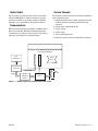
Control Console
User’s Manual
1241 Bundy Boulevard, Winona, Minnesota USA
Phone: +1 (507) 454-5300, Fax: +1 (507) 452-4507 http://www.watlow.com
Registered Company
Winona, Minnesota USA
0600-0045-0000 Rev C
*0600-0045-0000*
March 2004
$5.00
Safety Information
We use note, caution and warning symbols throughout this book to draw your attention to important
operational and safety information.
A "NOTE" marks a short message to alert you to an
important detail.
A "CAUTION" safety alert appears with information
that is important for protecting your equipment and
performance. Be especially careful to read and follow
all cautions that apply to your application.
A "WARNING" safety alert appears with information
that is important for protecting you, others and
equipment from damage. Pay very close attention to
all warnings that apply to your application.
The safety alert symbol, ç (an exclamation point in
a triangle), precedes a general CAUTION or WARNING statement.
The electrical hazard symbol, ∫ (a lightning bolt in
a triangle), precedes an electric shock hazard CAUTION or WARNING safety statement.
Technical Assistance
If you encounter a problem with this product, review
your configuration information to verify that your
selections are consistent with your application:
inputs, outputs, alarms, limits, etc. If the problem
persists, you can get technical assistance from your
local Watlow representative (see back cover), by emailing your questions to
[email protected] or by dialing +1 (507)
494-5656 between 7 a.m. and 5 p.m., Central
Standard Time (CST). Ask for an Applications
Engineer. Please have the following information
available when calling:
• Complete model number
• All controller configuration information
• User's Manual
• Wiring diagram.
Warranty
This product is warranted free from defects in material and workmanship for 36 months after delivery
to the first purchaser for use, providing that the
units have not been misapplied. Since Watlow has
no control over their use, and sometimes misuse, we
cannot guarantee against failure. Watlow's obligations hereunder, at Watlow's option, are limited to
replacement, repair or refund of purchase price, and
parts that upon examination prove to be defective
within the warranty period specified. This warranty
does not apply to damage resulting from transportation, alteration, misuse or abuse.
Return Material Authorization (RMA)
1. Call Watlow Customer Service, +1 (507) 4545300, for a Return Material Authorization (RMA)
number before returning any item for repair. We
need this information:
• Ship to address
• Bill to address
• Contact name
• Phone number
• Method of return shipment
• Your P.O. number
• Detailed description of the problem
• Any special instructions
• Name and phone number of person returning
the product.
2. Prior approval and an RMA number, from the
Customer Service Department, is needed when
returning any unused product for credit. Make
sure the RMA number is on the outside of the
carton, and on all paperwork returned. Ship on a
Freight Prepaid basis.
3. After we receive your return, we will examine
the unit and try to verify the reason for the
return.
4. In cases of manufacturing defect, we will enter a
repair order, replacement order or issue credit
for material returned.
5. To return products that are not defective, goods
must be in new condition, in the original boxes
and they must be returned within 120 days of
receipt. A 20-percent restocking charge is applied
for all returned stock controls and accessories.
6. If the unit cannot be repaired, it will be returned
to you with a letter of explanation.
7. Watlow reserves the right to charge for no trouble found (NTF) returns.
The Control Console User's Manual is copyrighted
by Watlow Winona, Inc., copyright March 2004 with
all rights reserved.
T
Control Console: Table of Contents
Chapter 1: Product Overview
List of Figures
Features and Benefits . . . . . . . . . . . . . . . . . .2
Figure 1 — Thermal system using a Control Console
Control Console Architecture . . . . . . . . . . . . .2
Power Requirements . . . . . . . . . . . . . . . . . . .2
with a limit . . . . . . . . . . . . . . . . . . . . . . . . . .3
Figure 2 — Rear view of console without the
Sensor Input . . . . . . . . . . . . . . . . . . . . . . . . . .2
communications option . . . . . . . . . . . . . . . .4
Heater Output . . . . . . . . . . . . . . . . . . . . . . . . .3
Figure 3 — Control Console without a limit . .5
Communications . . . . . . . . . . . . . . . . . . . . . . .3
Console Elements . . . . . . . . . . . . . . . . . . . . .3
Chapter 2: Installation & Wiring
Pre-Installation . . . . . . . . . . . . . . . . . . . . . . . .4
Installation . . . . . . . . . . . . . . . . . . . . . . . . . . . 4
Appendix
Specifications . . . . . . . . . . . . . . . . . . . . . . . . .6
Controllers . . . . . . . . . . . . . . . . . . . . . . . . . . .6
Output Power Switching . . . . . . . . . . . . . . . . .6
Power Requirements . . . . . . . . . . . . . . . . . . .6
Sensor Input . . . . . . . . . . . . . . . . . . . . . . . . . .6
Operating Environment . . . . . . . . . . . . . . . . . .6
Dimensions of Enclosure . . . . . . . . . . . . . . . .6
Accessory Parts . . . . . . . . . . . . . . . . . . . . . . .7
Ordering Information . . . . . . . . . . . . . . . . . . . .8
How to Reach Us . . . . . . . . . . . . . . . . . . . . .10
Watlow
Control Console ■ 1
Chapter One: Product Overview
Features and Benefits
• Fits easily into confined areas
• Easily transported
• Prewired output
• AMP Mate-'n'-Lok® or twist-and-lock output connector option on most configurations
• Miniature thermocouple connector
• Option of 1/32 or 1/16 DIN Series SD or Series 96
controllers.
• A 1/16 DIN size controller is not available in the
mini console.
• On-off rocker switch
• No external components required
• Quick installation and fast start up.
(Mate-'n'-lok® is a registered trademark of AMP
Company.)
The Watlow Control Console offers a complete control solution consisting of the temperature control(s),
thermocouple input(s), power-switching device(s) and
heater output(s), in a small package. Installation is
quick and easy; as few as three simple connections
and the console is ready for use in your application.
Each unit is supplied with a line cord, heater output
connector mates, thermocouple connector mates and
an on-off rocker switch. A solid-state relay is utilized
for fast, reliable switching of the load. The white,
powder-coated enclosure has vent openings on the
top and bottom for internal heat dissipation.
Control Console Architecture
This product comes in one, two or four zone configurations. The power cord, your choice of heater output
connector(s), the thermocouple input connector(s)
and communications connector (if applicable) are
mounted in the rear of the enclosure. All remaining
components are inside the enclosure.
Power Requirements
MINI, SNGL and Light Duty DUAL Control
Consoles are fused at 10 amps total, 8 amp maximum total load is recommended. The 120V Consoles
have a NEMA 5-15 plug. The 208/240V Consoles
have a NEMA 6-15 plug.
Heavy Duty DUAL Control Consoles are fused at 20
amps total. A 16 amp maximum total load is recommended. Each zone is individually fused at 10 amps
with 8 amps maximum load recommended.
The Heavy Duty DUAL contains a NEMA 5-20 plug.
Heavy Duty Controller/Limit Consoles are fused at
15 amps with 12 amps maximum load recommended.
Light Duty Controller/Limit Consoles are fused at 10
amps with 8 amps maximum load recommended.
QUAD consoles are fused at 20 amps total with 16
amps maximum load recommended. Each zone is
individually fused at 5 amps with 4 amps maximum
load recommended.
All models are available with 120V~ (ac) +10%/-15%
MINI, SNGL and Light Duty DUAL Consoles are
available with 208/240V~ (ac) +10%.
Sensor Input
The Consoles are ordered with a factory selectable
thermocouple (J, K or T) or 2-wire RTD.
The RTD option for the Series SD is only available
with a 100-ohm, platinum DIN curve.
The Series 96 has the option of JIS curve, which can
be selected by the user. Mating connectors are provided with the sensor input(s).
The console comes with 1/16 or 1/32 DIN Series SD
or Series 96 controller(s). A solid-state relay serves
as the output power-switching device and is powered
through the line cord.
2 ■ Control Console
Watlow
Heater Output
Console Elements
The Consoles are ordered with a factory selectable
choice of AMP Mate-'n'-Lok® connector(s) or twist
and lock connector(s) for heater output(s). Mating
connector(s) are provided for the heater output(s).
The Control Console contains the following elements
of the thermal system:
1. communications port for data acquisition included with consoles containing communications
(optional);
Communications
2. temperature controlling device;
EIA-232 Communications available on SNGL with a
Series 96 controller. EIA-485 Communications are
available on two and four zone Consoles. No mating
connector is provided for communications.
3. heater output;
4. sensor input;
5. power switching device;
6. limit for consoles with controller/limit (optional).
Heat Transfer Medium
S
e
n
s
o
r
Data
Acquisition
S
e
n
s
o
r
Work
Load
Temperature
Controller
Sensor Input
Output
Power
Switching
Device
Heat
Source
Limit
Figure 1 — Thermal system using a Control Console with a limit.
Watlow
Control Console ■ 3
Chapter Two: Installation & Wiring
Pre-Installation
ç CAUTION
High Temperature Limit: Only the Watlow Controller/Limit
console utilizes a high temperature limit control. Install
high temperature control protection in systems where an
overtemperature fault condition would present a fire hazard or other hazard. Failure to install temperature control
protection where a potential hazard exists could result in
damage to equipment and property, and injury to personnel.
ç WARNING
Fire Hazard: Extreme care should be taken to locate the
control console in a safe environment. Mounting the control console in atmospheres containing combustible
gasses and vapors should be avoided. According to
Article 501 of the National Electrical Code (NEC), the
maximum surface temperature of the enclosure shall not
exceed 80% of the auto-ignition of the surrounding
atmosphere when the control console is continuously
energized. Care should be taken to keep combustible
materials far enough away to be free of the effects of
high temperatures.
Figure 2 — Rear view of console without the communications option.
ç WARNING
Heater Output. Power is applied to the heater output terminals via the line cord. L1 is switched through the
solid-state relay to the connector and L2 is connected to
the heater output connector. DO NOT apply voltage to
the heater.
Installation
1. Wiring Connections
Wiring of the control consoles utilizes connections for
the thermocouple, input power and heater output.
The mating connectors are shipped with the consoles. It is the user's responsibility to properly size
and install feeder wire.
Refer to Figure 2 for 120V layout. Refer to Figure 3
for wiring diagram.
4 ■ Control Console
Watlow
Power Cord
Controller
L1
L2
GND
Output Connector
Power Power
Output
Output
Input Input
In
In
Ground
In
In
Ground
Vdc
Vac
Out
Out
Vdc
Vac
Out
Out
Solid-state Relay
Heater Element
Input Connector
In
In
In
In
Thermocouple
Figure 3 — Control Console without a limit.
EIA-485 Communications
2. Heater Connections
• Female DB9 connector mounted in box
The heater output(s) utilizes either AMP Mate-’n’Lok® connector(s) or twist-and-lock connector(s).
The mating connector and terminals are provided.
• Pin 2: T-/R-(A)
To ensure proper crimping of the AMP Mate-’n’-Lok®
terminals, the proper equipment should be used.
AMP recommends using part number 90300-2 for
terminal crimping and part number 458994-2 for
extraction of the terminals from the connector.
Please consult the TYCO-AMP Corporation at 1-800468-2023 for further information.
• Pin 5: common
3. Thermocouple Connections
Using a small screwdriver, remove the two screws
holding the cover of the male miniature thermocouple connector(s). Loosen, but do not remove the +
and - terminal screws. The connector(s) can accommodate wire sizes up to 20-gauge, stranded wire.
Insert the red wire from the thermocouple to the (-)
terminal of the connector(s). Do not wrap the wire
around the terminal. Repeat the step for the positive
thermocouple lead.
• Pin 3: T+/R+(B)
* To ensure proper crimping of the DB9 terminal,
the proper equipment should be used. AMP recommends using part number 58448-2.
5. Start Up
For start up and function of the temperature controller, please refer to the user's manual for the
respective temperature controller that is included
with the Console.
4. Communication Connections
EIA-232 Communications
• Female DB9 connector mounted in box
• Pin 2: receive
• Pin 3: transmit
• Pin 5: common
Watlow
Control Console ■ 5
Appendix
Specifications
Sensor Input
Controllers
• Factory selectable thermocouple (J, K or T) or 2wire RTD.
• Watlow Series 96 (Refer to Series 96 User's
Manual for controller specifications.)
• Watlow Series SD (1/16 or 1/32 DIN), (Refer to
Series SD User's Manual for controller/limit
specifications.)
• RTD for Series SD series only available as 100ohm, platinum DIN curve.
• Series 96 has option of DIN or JIS curve, which
can be selected by user.
• Watlow Series 97 (Refer to Series 97 User's
Manual for controller/limit specifications.)
• Choice of AMP Mate-'n'-Lok® connector(s) or
twist-and-lock connector(s) for heater output(s).
Power Requirements and Output Power
Switching
• Mating connector(s) provided.
• Utilizes solid-state relay.
• Output is powered through the line cord.
• MINI, SNGL, and Light Duty DUAL Control
Consoles are fused at 10 amps total, 8 amp maximum total load is recommended.
• 120V have NEMA 5-15 plug
• 208/240V have NEMA 6-15 plug
• Heavy Duty DUAL Control Consoles are fused at
20 amps total, 16 amp maximum total load is
recommended. Each zone is individually fused at
10 amps with 8 amps maximum load recommended.
• NEMA 5-20 plug
• Heavy Duty Controller/Limit Consoles are fused
at 15 amps with 12 amps maximum load recommended.
• Light Duty Controller/Limit Consoles are fused
at 10 amps with 8 amps maximum load recommended.
• EIA-232 communications available in SNGL control consoles with a Series 96 controller.
• EIA-485 communications are available in DUAL
and QUAD Control Consoles with a Series 96
controller.
• EIA-485 to EIA-232 communications converters
and power supplies are available from Watlow.
Operating Environment
• 0 to 45°C (32 to 113°F)
• 0 to 90% RH, noncondensing
Dimensions of Enclosure
Console
Height
Width
Mini
76 mm
90 mm
3.0 in
3.5 in
Depth
180 mm
7.1 in
Single 119 mm
4.7 in
76 mm
3.0 in
191 mm
7.5 in
Dual
121 mm
4.75 in
152 mm
6.0 in
187 mm
7.375 in (SD)
Quad
114 mm
4.5 in
305 mm
12.0 in
191 mm
7.5 in
• QUAD consoles are fused at 20 amps total with
16 amps maximum load recommended. Each
zone is individually fused at 5 amps with 4 amps
maximum load recommended.
• All models are available with 120V~ +10%/-15%.
• MINI, SNGL and Light Duty DUAL consoles are
available with 208/240V~ +10%.
• 208/240V fused for domestic use only (both lines
fused).
6 ■ Control Console
Watlow
Accessory Parts
Manufacturer
Description
Manufacturer’s Part
Number
Relationship to
Console
Tyco-Amp
Mate-n-Lok® Plug
1-480698-0
Ship with
Tyco-Amp
Mate-n-Lok® Plug
350550-1
Ship with
Hubbell
Plug
7465V
Ship with 120V units
Hubbell
Plug
7485
Ship with 208/240V
units
Tyco-Amp
DB9 (male)
205204-1
Ship with
Tyco-Amp
DB9 (pins)
1-66506-0
Ship with
B&B
Electronics
MRS 232-485 Converter
485SD9TB
Watlow part number
0830-0473-0001
B&B
Electronics
MRS 232-485 Converter
485PS2
Watlow part number
0830-0473-0002
Mate-'n'-lok® is a registered trademark of AMP Company.
Watlow
Control Console ■ 7
Ordering Information
To order, complete the model number using the
information below.
Control Console: Mini
Single zone
Self-contained unit
MINI -
-0000
Input
J
Type J thermocoule
K Type K thermocouple
T Type T thermocouple
R RTD (100 ohm, 2-wire)
Controllers
G Series SD (1/32 DIN) w EIA-485 comms
5 Series SD (1/32 DIN)
Display Color
R Red/Green
Line Voltage
1 120VÅ (ac)
2 208/240VÅ (ac)
Control Console: Dual
Two zones
Self-contained unit
DUAL-
-
00
Controllers
A Series 96 w ramp and soak
B Series 96/97 w ramp and soak
E Series 96 w EIA-485 comms
F Series SD (1/16 DIN) w EIA-485 comms
G Series SD (1/32 DIN) w EIA-485 comms
4 Series 96
5 Series SD (1/32 DIN)
7 Series SD (1/16DIN)
8 Series 96/97 Controller/Limit *
9 Series SD6C/SD6L Controller/Limit *
0 Series SD6C/SD3L Controller/Limit *
Input
J
Type J thermocoule
K Type K thermocouple
T Type T thermocouple
R RTD (2-wire)
Display Series 96/97/SD
RG Red/Green (only option on Series SD 1/32 DIN)
RR Red/Red
GG Green/Green (only available on Series 96 & 97)
GR Green/Red (only available on Series 96 & 97)
Output Connector
1 Amp Mate-’n’-Lok®
2 Twist and lock
Line Voltage
1 120VÅ (ac) (light duty: 4 A per zone; 8 A total)
2 208/240VÅ (ac) (light duty: 4 A per zone; 8 A total)
3 120VÅ (ac) (heavy duty: 8 A per zone; 16 A total)
*Control Limit
Light Duty: 8 A total
Heavy Duty: 12 A total
8 ■ Control Console
Watlow
Control Console: SNGL
SNGLSingle zone
Self-contained unit
00
-
Controllers
A Series 96 w ramp & soak
C Series 96 w ramp & soak, EIA-232 comms
G Series SD (1/32 DIN) w EIA-485 comms
4 Series 96
5 Series SD (1/32 DIN)
6 Series 96 w EIA-232 comms
7 Series SD (1/16DIN)
Input
J
Type J thermocoule
K Type K thermocouple
T Type T thermocouple
R RTD (2-wire)
Display Series 96/SD
RG Red/Green (only option on Series SD 1/32 DIN)
RR Red/Red
GG Green/Green (only available on Series 96)
GR Green/Red (only available on Series 96)
Output Connector
1 Amp Mate-’n’-Lok®
2 Twist and lock
Line Voltage
1 120VÅ (ac)
2 208/240VÅ (ac)
Control Console: Quad
Four zones
Self-contained unit
QUAD-
-
00
Controllers
A Series 96 w ramp and soak
E Series 96 w EIA-485 comms
F Series SD (1/16 DIN) w EIA-485 comms
G Series SD (1/32 DIN) w EIA-485 comms
4 Series 96
5 Series SD (1/32 DIN)
7 Series SD (1/16DIN)
Input
J
Type J thermocoule
K Type K thermocouple
T Type T thermocouple
R RTD (2-wire)
Display Series 96/SD
RG Red/Green (only option on Series SD 1/32 DIN)
RR Red/Red
GG Green/Green (only available on Series 96 & 97)
GR Green/Red (only available on Series 96 & 97)
Output Connector
1 Amp Mate-’n’-Lok®
2 Twist and lock
Line Voltage
1 120VÅ (ac)
Watlow
Control Console ■ 9
How to Reach Us
Your Authorized Watlow Distributor:
United States (headquarters):
Asia/Pacific:
Watlow Electric Manufacturing Company
12001 Lackland Road
St. Louis, Missouri USA 63146
Telephone: +1 (314) 878-4600
Fax: +1 (314) 878-6814
Watlow Australia Pty., Ltd.
23 Gladstone Park Drive,
Tullamarine, Victoria 3043 Australia
Telephone: +61 (39) 335-6449
Fax: +61 (39) 330-3566
Europe:
Watlow GmbH
Industriegebiet Heidig
Lauchwasenstr. 1, Postfach 1165,
Kronau 76709 Germany
Telephone: +49 7253-9400 0
Fax: +49 7253-9400 44
Watlow China, Inc.
179, Zhong Shan Xi Road
Hong Qiao Cointek Bldg, Fl. 4, Unit P
Shanghai 200051 China
Telephone: +86 (21) 6229-8917
Fax: +86 (21) 6228-4654
Watlow France S.A.R.L.
Immeuble Somag, 16 Rue Ampère,
Cergy Pontoise CEDEX 95307 France
Telephone: +33 (1) 3073-2425
Fax: +33 (1) 3073-2875
Watlow Japan Ltd. K.K.
Azabu Embassy Heights 106,
1-11-12 Akasaka,
Minato-ku, Tokyo 107-0052 Japan
Telephone: +81 (03) 5403-4688
Fax: +81 (03) 5403-4646
Watlow Italy S.R.L.
Via Meucci 14
20094 Corsico MI
Italy
Telephone: +39 (02) 4588841
Fax: +39 (02) 458-69954
Watlow Korea Co., Ltd.
Hanil Bldg., 3rd Floor
210-5 Yangje-Dong Seocho-Gu
Seoul, 137-130 Korea
Telephone: +82 (2) 575-9804
Fax: +82 (2) 575-9831
Watlow Limited
Robey Close, Linby Industrial Estate,
Linby Nottingham England, NG15 8AA
Telephone: +44 (0) 115 9640777
Fax: +44 (0) 115 9640071
Watlow Malaysia Sdn Bhd
38B Jalan Tun Dr Awang
11900 Bayan Lepas
Penang Malaysia
Telephone: +60 (4) 641-5977
Fax: +60 (4) 641-5979
Latin America:
Watlow de México
Av. Fundición #5,
Col. Parques Industriales,
Querétaro, Qro. México CP-76130
Telephone: +52 (442) 217-6235
Fax: +52 (442) 217-6403
Watlow Singapore Pte. Ltd.
Ayer Rajah Crescent
#03-23 Ayer Rajah Industrial Estate
Singapore 139949
Telephone: +65 773 9488
Fax: +65 778 0323
Watlow Electric Taiwan
10F-1 No. 189
Chi-Shen 2nd Road,
Kaohsiung, Taiwan
Telephone: +886 (7) 288-5168
Fax: +886 (7) 288-5568