1
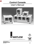
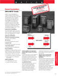
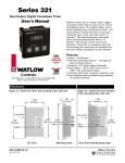
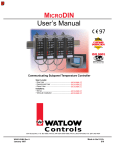
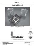
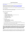
1 Wa t l o w M i c r o D I N Q u i c k S t a r t G u i d e
MicroDIN Quick Start Guide
Communicating Subpanel Temperature Controller
Watlow Winona
1241 Bundy Blvd., P.O. Box 5580, Winona, MN 55987-5580
Phone: (507) 454-5300, Fax: (507) 452-4507
www.watlow.com
0600-0011-0002 Rev B
February 2003
$5.00
2
Watlow MicroDIN Quick Start Guide
Introduction to the MicroDIN Controller
The Watlow MicroDIN controller is a DIN rail-mounted, temperature controller.
It uses one input and two outputs, network connections and dozens of parameters to satisfy a broad variety of control needs.
The single input can use either a thermocouple or RTD sensor. The single control output provides an open collector or switched dc output signal for a power
switching device with a DC input. The single alarm output is an electromechanical relay. The network connections allow as many as 32 controllers to be configured and monitored from a single personal computer.
You can configure, operate and monitor the MicroDIN almost entirely from a
PLC or personal computer via a serial connection using RJ-11 jacks. Indicator
lights on the face of the controller monitor error states, power, communications
activity and output activity.
Communications Input and Output
to and from Personal Computer
MicroDIN
MicroDIN
MicroDIN
MicroDIN
Temperature Controller
Temperature Controller
Temperature Controller
Temperature Controller
Address
Power
Power
Power
Comms
Comms
Comms
Power
Comms
Control
Output
Control
Output
Control
Output
Control
Output
Alarm
Alarm
Alarm
Alarm
Input
Error
Input
Error
Input
Error
Input
Error
1
Address
2
Address
3
Address
4
1-32 devices/
EIA-485 Network
Figure 2 - MicroDIN
inputs and outputs in a
thermal system
Per Unit:
• Sensor Input from the process
• Control Output to the process
• Alarm Output about the process
Note: An electronic copy of this MicroDIN Quick Start Guide and the full version
MicroDIN User’s Manual is available at www.watlow.com/prodtechinfo. Search on
keyword MicroDIN.
3
Watlow MicroDIN Quick Start Guide
Setup Steps
1. Set up communications.
2. Set the controller’s address and baud speed with the DIP switches on the top
panel (see page 6). The controller uses eight data bits with no parity.
3. Mount the controller (see pages 9 and 10).
4. Wire the controller (see pages 12-14).
5. Communicate with MicroDIN via an EIA-485 network with Modbus™
RTU protocol.
Indicator Lights
Figure 3 - MicroDIN
indicator lights
Power
Green light stays
lit when the power is on
and the controller is ok.
• If it isn’t on or pulsates,
check your power source.
MicroDIN
Temperature Controller
Power
Control Output
Green light is lit or flashes
when the control output is
energized.
• If it does not light up, the
output is not turning on.
Alarm
Red Light is lit during an
input alarm condition.
If it is lit:
• Correct alarm condition
or change alarm configuration.
• Reset the alarm if it is
latched.
Comms
Control
Output
Alarm
Input
Error
Address
Communications
Green Light pulsates when the
controller sends or receives
valid data over its network port.
• If it does not light up, check
the controller address and the
communications setup.
Input Error
Red Light is lit if there is a sensor problem. If it is lit:
• Verify the sensor wiring,
polarity and function.
• Rewire or replace as necessary.
Address Field
Record the unit’s address in
erasable marker here.
4
Watlow MicroDIN Quick Start Guide
Communications Overview
EIA-485 Network
The MicroDIN uses the EIA-485 (formerly, “RS-485”) hardware interface to communicate with three wires in a half-duplex configuration, up to 32 remote
devices with a master unit on a network up to 4,000 feet long using 14-26 gauge
wire.
Modbus™ Protocol
The MicroDIN uses Modbus™ RTU protocol to read and write to registers that
can be viewed or changed from a personal computer. Each MicroDIN ‘parameter’
has a corresponding Modbus™ register and access privileges. The MicroDIN parameter register numbers and the order of priority appear later in this chapter.
Chapter 5 details all the MicroDIN parameters, and the Appendix provides information on how to write custom Modbus™ applications
Set Address/Baud Rate
You must configure the communications speed and network address of the
MicroDIN controller with the eight-bit DIP switch on the top of the unit. Set the
controller address with the first six switches and the network speed (9,600 or
19,200 baud) with the eighth switch. Turn to the DIP switch page 6.
Serial Data Format
The MicroDIN uses the an 8-N-1 data format; 8 data bits, no parity, 1 stop bit,
and 1 start bit. See the data format table later in this chapter.
Wiring Tasks
In addition to wiring the controller’s input, outputs and power connections, you
must also wire the EIA-232-to-EIA-485 converter; connect your computer to the
MicroDIN, and connect the MicroDIN communications daisy chain. See
“Communications Wiring” on pages 14 and 15.
Communications Software
Watlow offers a Windows application for MicroDIN, called, WATVIEWTM which
will both set up and run multiple MicroDINs over an EIA-485 network using the
Modbus™ protocol. For more information on WATVIEWTM, , go to www.watlow.
com/products/software.
You may also write your own application (see Appendix for more detail), or purchase any of several available Modbus-capable control software packages.
5
Watlow MicroDIN Quick Start Guide
Modbus™ Register Numbers
Address
Address
Absolute Relative Parameters
Absolute Relative Parameters
40001
0
Model Number (Diagnostics)
40601
600
Sensor Type (Input)
40002
1
Serial Number (Characteristics)
40602
601
Input Type (Input)
40003
2
Serial Number 2 (Characteristics)
40603
602
Range Low (Input)
40004
3
Software ID number (Characteristics)
40604
603
Range High (Input)
40005
4
Software Revision (Characteristics)
40605
604
Filter Time Constant (Input)
40006
5
Date of Manufacture (Characteristics)
40606
605
Calibration Offset (Input)
40007
6
Ship Date (Characteristics )
40607
606
Decimal Point (System)
40017
16
Control Output Hardware (Control Output)
40608
607
Error Clearing Mode (Error)
40018
17
Alarm Output Hardware (Alarm)
40701
700
Control Output Function (Control Output)
40025
24
Disable Non-volatile Memory (System)
40714
713
Power Limit Set Point (Control Output)
40101
100
Input Actual (Input)
40715
714
High Side Power (Control Output)
40102
101
Input Error (Input)
40716
715
Low Side Power (Control Output)
40104
103
Output Power (Control Output)
40718
717
Alarm Output Function (Alarm Output)
40107
106
Alarm Condition (Alarm Output)
40720
719
Alarm Type (Alarm Output)
40201
200
Operation Mode (Operation)
40721
720
Alarm Hysteresis (Alarm Output)
40205
204
PID Output Power (PID)
40722
721
Alarm Latching Mode (Alarm Output)
40206
205
Proportional Term (PID)
40723
722
Alarm Silencing Mode (Alarm Output)
40207
206
Integral Term (PID)
40724
723
Alarm Active Sides (Alarm Output)
40208
207
Derivative Term (PID)
40725
724
Alarm Logic (Alarm Output)
40210
209
System Error (Error)
40901
900
Units Type (System)
40211
210
Open Loop Error (Error)
40902
901
C or F (System)
40301
300
Set Point (Operation)
40903
902
Input Error Action (Input)
40302
301
User Operation Mode (Operation)
40904
903
Fixed Manual Output (Control Output)
40305
304
Auto-tune Set Point (PID)
40905
904
Activate Open Loop Detect (Error)
40306
305
Initiate Auto-tune (PID)
41501
1500
Ambient (CJC) Temperature (System)
40311
310
Manual Output Power (Operation)
41502
1501
Ambient (CJC) A-to-D Counts (Diagnostics)
40312
311
Clear Error (Error)
41503
1502
RTD Lead Compens. A-to-D Counts (Diag)
40322
321
Alarm Low (Alarm Output)
41504
1503
RTD Lead Resistance (Diagnostics)
40323
322
Alarm High (Alarm Output)
41505
1504
Input A-to-D Counts (Diagnostics)
40332
331
Clear Alarm (Alarm Output)
41513
1512
Enter Diagnostics Mode (Diagnostics)
40333
332
Silence Alarm (Alarm Output)
41514
1513
Test Displays (Diagnostics)
40501
500
Proportional Band (PID)
41515
1514
Test Outputs (Diagnostics)
40502
501
Integral (PID)
41601
1600
Enter Calibration Mode (Calibration)
40503
502
Reset (PID)
41602
1601
Restore to Factory Calibration (Calibration)
40504
503
Derivative (PID)
41603
1602
Reset Factory Defaults (Calibration)
40505
504
Rate (PID)
41604
1603
Calibration Commands (Calibration)
40507
506
Cycle Time (PID)
40508
507
Control Output Hysteresis (PID)
6
Watlow MicroDIN Quick Start Guide
MicroDIN DIP Switches Set Address/Baud Rate
Configure the communications speed and network address of the MicroDIN controller with the eight-bit DIP switch on the top panel. Set the controller address
with the first six switches. Set an address between 1 and 63. The network will
not work correctly if any two controllers have the same address. DIP switch 1
sets the left-most binary digit. Switch 6 sets the right-most digit.
Record the MicroDIN’s address in erasable marker
on the white space on the front of the unit.
The seventh switch has no effect.
Set the network speed (9,600 or 19,200 baud) with the eighth switch.
Figure 6 MicroDIN top view with
DIP switches and baud
settings
O
N
↑
O
N
↑
1 2 3 4 5 6 7 8
9600 baud
(bit 8 on)
1 2 3 4 5 6 7 8
19.2k baud
(bit 8 off)
1 2 3 4 5 6 7 8
O
N
↑
Top View
O
N
↑
Table 6 Decimal-to-binary conversion
Dec.
1
2
3
4
5
6
7
8
9
10
11
12
13
14
15
1 2 3 4 5 6 7 8
Binary
000001
000010
000011
000100
000101
000110
000111
001000
001001
001010
001011
001100
001101
001110
001111
O
N
↑
Dec.
16
17
18
19
20
21
22
23
24
25
26
27
28
29
30
31
1 2 3 4 5 6 7 8
Binary
010000
010001
010010
010011
010100
010101
010110
010111
011000
011001
011010
011011
011100
011101
011110
011111
O
N
↑
Dec.
32
33
34
35
36
37
38
39
40
41
42
43
44
45
46
47
1 2 3 4 5 6 7 8
Binary
100000
100001
100010
100011
100100
100101
100110
100111
101000
101001
101010
101011
101100
101101
101110
101111
O
N
↑
Dec.
48
49
50
51
52
53
54
55
56
57
58
59
60
61
62
63
1 2 3 4 5 6 7 8
Binary
110000
110001
110010
110011
110100
110101
110110
110111
111000
111001
111010
111011
111100
111101
111110
111111
7
Watlow MicroDIN Quick Start Guide
Required Parameters Setup Order
This table provides 1) the correct order of entry, 2) the effect of a parameter change, and 3) a place to document settings.
Parameters
should be set
up in this order.
Uni
ts T
ype
Co
rF
Con
trol
Out
Sen
put
sor
Fun
T
ctio
y
p
Inpu
e
n
t Ty
p
e
Ran
ge
Ran Low
ge H
igh
Hig
hS
ide
Pow
Low
er
Side
Pow
Alar
er
mT
ype
Ope
rati
Dec on Mod
ima
e
l
çCAUTION:
➝
➝
Changing this ➝
Affects this
Units Type
C or F
Input Error Action
Control Output Function
Set Fixed Manual Output
Open Loop Detect
Sensor Type
Input Type
Range Low
Range High
Decimal Point
Calibration Offset
Filter Time Constant
Error Clearing Mode
Power Limit Set Point
High Side Power
Low Side Power
Alarm Output Function
Alarm Type
Alarm Hysteresis
Alarm Latching Mode
Alarm Silencing Mode
Alarm Active Sides
Alarm Logic
Alarm High
Alarm Low
Propband
Integral
O
Reset
O
Derivative
Rate
Cycle Time
Output Hysteresis
Operation Mode
Set Point
Manual Output Power
Set Point
Table 7 - Parameters Setup order
O
O
D
D
D
D
D
C
C
D
D
D
D
D
C
C
D D
C
C
D D
D D
C
C
C
C
D D
D D
D D
C
D D
C
C
C
O
O
O
C
O
O
C
O O
D D O O
C
C
C
O
C
Key:
D = Changing will change the
default
C = Changing will convert the temperature scale
O = Other effect (see Ch. 5)
Document your settings below
8
Watlow MicroDIN Quick Start Guide
Serial Data Format
Configure your computer’s COM1 or COM2 (communications) port data format to
match the MicroDIN’s settings in the table below.
Table 8a Serial Data Format
Data Bits
Parity
Stop Bit
Start Bit
8
None
1
1
MicroDIN Installation Wiring Tasks
MicroDIN requires these wiring tasks for a successful installation
1. Wire MicroDIN sensor input.
2. Wire MicroDIN Output 1, the control output.
3. Wire MicroDIN Output 2, the alarm output.
4. Wire MicroDIN power.
5. Connect the MicroDIN communications daisy chain.
6. Wire the 232-to-485 converter; connect to the computer.
7. If necessary, wire the termination and pull-up/pull-down resistors.
Communications Software
WATVIEWTM
Figure 8b WATVIEW™ sample software screen
Watlow offers a
Modbus™ package
in WATVIEW™,
software that will
set up and run
multiple
MicroDINs over
an EIA-485
network.
WATVIEW™ is
available from
any Watlow sales
representative or
authorized distributor. For more
information, go to
www.watlow.com
/products/software. WATVIEW™ can handle up to 32 MicroDIN units.
Other Software
To communicate with MicroDIN, you must use a Modbus™ RTU (remote terminal
unit) compatible software package. Sending ASCII commands via a standard
serial communication application will not work. Refer to the Appendix in the
User's Manual if you’re writing your own Modbus™ RTU application.
9
Watlow MicroDIN Quick Start Guide
Mounting the MicroDIN
To mount a MicroDIN on a DIN rail, hook the upper lip of the rail mounting
bracket onto the rail and press the controller down until the bottom lip of the
mount snaps onto the rail. To remove, as you push the back of the controller
down lift the front up until the bottom lip unsnaps from the rail.
To mount a MicroDIN on a panel, use the dimensions below to drill screw holes
for the mounting bracket.
Figure 9 Mounting a
MicroDIN controller
bracket for
panel mounting
(#6 screw
or m3.5 required)
.318 in
(8 mm)
Top/bottom
mount
hole offset
Side View
MicroDIN
Temperature Controller
Power
4.225 in
(107 mm)
3.750 in
(146 mm)
Comms
Control
Output
DIN
rail
4.650 in
(118 mm)
Alarm
Input
Error
Address
5.062 in
(129 mm)
Min. Clearance
between rail
Front View
centerlines
5.750 in
(146 mm)
Min. Clearance 2 in
(51 mm)
1.637 in
(42 mm)
2.875 in
(73 mm)
MicroDIN
MicroDIN
Temperature Controller
Temperature Controller
Power
Power
DIN
rail
ç
CAUTION:
Maintain the correct
spacing between rows of
controllers to allow sufficient air circulation and
installation clearance.
Failure to do so could
result in damage to
equipment.
Address
Comms
Comms
Control
Output
Control
Output
Alarm
Alarm
Input
Error
Input
Error
Address
1.650 in
(42 mm)
Attachment Angle
10°
Use DIN EN 50022 35mm x 7.5mm Rail
10
Watlow MicroDIN Quick Start Guide
Mounting the MicroDIN on a DIN rail
To Mount MicroDIN
1. Push unit in and down to catch rail hook
on top of rail.
2. Rotate bottom of unit in toward rail.
①
3. Rail clasp will audibly “snap” into place.
If the MicroDIN does not snap into place,
check to see if the rail is bent.
Figure 10a Mounting a MicroDIN
controller on a DIN rail
➂ "Snap"
➁
To Dismount MicroDIN
1. Press down on back of controller until the
bottom hook clears the rail.
①
2. Then rotate bottom up and away from
rail.
➁
Figure 10bDismounting a MicroDIN
controller from a DIN rail
11
Watlow MicroDIN Quick Start Guide
MicroDIN RJ-11 and 10-pin Connectors
The MicroDIN 10-pin screw terminal connector, on the bottom of the case, links
it to its power supply, control input, control output and alarm output. Use 26- to
14-gauge wire to connect to the plug terminals.
The alarm output is an electromechanical relay.
See the Appendix for information on sensor ranges and specifications. See
Chapter 5: Parameters for information about software configuration.
ABCD
Figure 11 - Bottom view
of MicroDIN case with
connector assignments
communications
sockets 1 and 2
(RJ-11)
Bottom View
Ó
Front of Unit
WARNING:
To avoid potential electric shock, use National
Electric Code (NEC) safety practices when wiring
and connecting this unit
to a power source and to
electrical sensors or
peripheral devices.
Failure to do so could
result in injury or death.
1
2
3
4
5
6
7
8
9
10
1 2 3 4 5 6 7 8 9 10
10-pin removable connector
ç
WARNING:
Install high or low temperature limit control protection in systems where
an over temperature fault
condition could present a
fire hazard or other hazard. Failure to install
temperature limit control
protection where a potential hazard exists could
result in damage to
equipment and property
and injury to personnel.
Input
1. S1 or thermocouple+
2. S3 or thermocouple3. S2
Control Output
4. dc+
5. dc6. common (COM)
Alarm Output (electromechanical relay)
7. alarm normally open (NO)
8. alarm common (COM)
Power
9. L2, 24V‡ (ac/dc)10. L1, 24V‡ (ac/dc)+
12
Watlow MicroDIN Quick Start Guide
Input Wiring
Figure 12a — MicroDIN Isolation Diagram
Power Supply
Safety
Isolation
Logic
and
Input
Outputs
UL/CE
Comms
500V
Noise
Isolation
Control
Output
Alarm
Figure 12b — Control Input, Thermocouple
1 2 3 4 5 6 7 8 9 10
+
-
Figure 12c — Control Input, 2-wire RTD
1 2 3 4 5 6 7 8 9 10
S1 S3
Figure 12d — Control Input, 3-wire RTD
1 2 3 4 5 6 7 8 9 10
S1
S2
S3
13
Watlow MicroDIN Quick Start Guide
Output and Power Wiring
Figure 13b —
Control Output, Open Collector
with External Power Supply
dc
+
dc
C
O
M
dc
+
dc
C
O
M
Figure 13a —
Control Output, Switched DC
with Internal Power Supply
1 2 3 4 5 6 7 8 9 10
1 2 3 4 5 6 7 8 9 10
+
External
External
Switching
Load
Device
External
External
Switching
Load
Device
-
- Power
+
+ 42V max.
Supply
1A max.
Figure 13c — Internal Output Circuitry
Ó
WARNING:
To avoid potential electric shock, use National
Electric Code (NEC) safety practices when wiring
and connecting this unit
to a power source and to
electrical sensors or
peripheral devices.
Failure to do so could
result in injury or death.
+24VÎ(dc)
2KΩ
20Ω
Internal Circuitry
4
dc+
5
6
dc- COM
Figure 13d — Alarm Output
N
.O
C .
O
M
Figure 3.4e — Power Wiring
1 2 3 4 5 6 7 8 9 10
1 2 3 4 5 6 7 8 9 10
Fuse
NOTE:
Relay suppression
required only for inductive loads.
Relay
Suppression
L1
24V‡ (ac/dc)
External
Load
- +
L2
Ó
WARNING:
If high voltage is applied
to a this 24V controller,
irreversible damage will
occur.
14
Watlow MicroDIN Quick Start Guide
Communications Wiring
Figure 14a- MicroDIN
communications daisy
chain via RJ-11
connectors
MicroDIN
MicroDIN
MicroDIN
MicroDIN
Temperature Controller
Temperature Controller
Temperature Controller
Temperature Controller
Power
Power
Power
Comms
Comms
Comms
Comms
Control
Output
Control
Output
Control
Output
Control
Output
Alarm
Alarm
Address
Alarm
Input
Error
Input
Error
Note: If your network
doesn’t function, see
Special 485 Network
Considerations section.
Address
1
2
Power
Alarm
Input
Error
Address
Input
Error
Address
3
4
Converter-To-MicroDIN Wiring Example
RJ-11 to MicroDIN
Ó
WARNING:
To avoid potential electric shock, use National
Electric Code (NEC) safety practices when wiring
and connecting this unit
to a power source and to
electrical sensors or
peripheral devices.
Failure to do so could
result in injury or death.
AB CD
TD (A)
TD (B)
RD (A)
RD (B)
TD (A)
TD (A)
SIG GND
EIA-485
EIA-232
Figure 14b- B&B
Converter to MicroDIN
Wiring
(B&B Electronics
Manufacturing Company,
Ph. 815-433-5100)
www.bb-elec.com
Green
Yellow
EIA-485
+
– Power Supply
AD-1210
120V~
120VÅ (Vac)
DI/O DI/O
EIA-485
ADA485L
G
B
A
B
A
9ÎVdc (see NOTE)
Comms Plug
Yellow
Red
Green
Yellow
AB CD
EIA232
G
9VDC
Figure 14c - CMC
0219-0217-0000
Converter to MicroDIN
7 ft. comms cable
Wiring
(CMC Connecticut MicroComputer, Inc.
Ph. 800-426-2872)
Note: The CMC converter requires an external power supply when used with a laptop.
www.2cmc.com
15
Watlow MicroDIN Quick Start Guide
Special EIA-485 Network Considerations
If your MicroDIN network doesn't work, it may need termination and pull-up
and pull-down resistors; wire them per the diagrams below.
Figure 15 a- Termination
for MicroDIN; RJ-11
phone plug with 120Ω
resistor across C and D
ABCD
RJ-11 Terminals
C (green) and D (yellow)
120Ω
Plug terminator into open socket in MicroDIN controller furthest from computer,
the last unit on the network.
Figure 15b Termination for
EIA-232/EIA-485
Converter with pull-up
and pull-down resistors
+5V
Converter box
termination
with pull-up
and pull-down
resistors.
B
T+/R+
A
T-/R-
GND
Com
1KΩ
120Ω
1KΩ
16
Watlow MicroDIN Quick Start Guide
Ó
WARNING:
To avoid potential electric shock, use National
Electric Code (NEC) safety practices when wiring
and connecting this unit
to a power source and to
electrical sensors or
peripheral devices.
Failure to do so could
result in injury or death.
120V~(ac)
L1
1
3
1
+
4
2
–
5
2
1
3
L2
0830-0474-0000
Supply
3 Power
2
– +
6
Loop
PC
EIA485 EIA485
7
4 5 6
3
8
8
7
2
MicroDIN
UD1A-1CES-0000
9 10
9
1CR-1
4
10
1
11
11
Semiconductor
Fuse
2
2
1
5
9
6
8
6
2
DIN-a-mite
DA10-24C0-0000
5
3
4
146E-1601-1000
Figure 16 System wiring example,
ladder diagram
7
8
3
–
9
10
ç
WARNING:
Install high or low temperature limit control protection in systems where
an over temperature fault
condition could present a
fire hazard or other hazard. Failure to install
temperature limit control
protection where a potential hazard exists could
result in damage to
equipment and property
and injury to personnel.
12
1
10
11
13
18
5
20
2
2
1 CR
7
2
17
Series 146
Limit Control
1
12
+ 15
16
11
Heater
14
1
High Temp. Light
9
13
14
21
19
Optional
Normally Open
Momentary
Switch
2
17
Watlow MicroDIN Quick Start Guide
Wiring Examples
Figure 17 System wiring example,
schematic
L1
120VÅ (ac)
L2
Branch
Circuit Fuse
Earth Ground
Watlow
MicroDIN
Ó
WARNING:
To avoid potential electric shock, use National
Electric Code (NEC) safety practices when wiring
and connecting this unit
to a power source and to
electrical sensors or
peripheral devices.
Failure to do so could
result in injury or death.
ç
WARNING:
Install high or low temperature limit control protection in systems where
an over temperature fault
condition could present a
fire hazard or other hazard. Failure to install
temperature limit control
protection where a potential hazard exists could
result in damage to
equipment and property
and injury to personnel.
High Limit
Mechanical
Contactor
Coil
Semiconductor
Fuse
0830-0474-0000
Power Supply
Temperature
Controller
UD1A-CES-0000
1
(-)
(+)
1 2 3 4 5 6 7 8 9 10
(-)
(+)
R
12345 6789
2
EIA485
Loop
Heater
PC
OR
146E-1601-1000
DIN-A-MITE
6
5 DA10-24C0-0000
4
3
Thermocouples
EIA485 to RS232
Converter
High
temp.
light
ModBus
Converter
Limit Control
10 11 121314 151617
Optional
Normally
Open
Momentary
Switch
18
Watlow MicroDIN Quick Start Guide
Declaration of Conformity
MicroDIN
Watlow Winona, Inc.
1241 Bundy Blvd.
Winona, MN 55987 USA
Declares that the following product:
Designation:
MicroDIN
Model Numbers:
UD1A – 1CES – (Any four letters or numbers)
Classification:
Temperature control, Installation Category II, Pollution degree 2
Rated Voltage:
24V‡ to 24V‡ (ac or dc)
Rated Frequency:
50 or 60 Hz
Rated Power Consumption: 5VA maximum
Meets the essential requirements of the following European Union Directives by using the relevant
standards show below to indicate compliance.
89/336/EEC Electromagnetic Compatibility Directive
EN 61326:1997 A1:1998
Electrical equipment for measurement, control and laboratory use – EMC requirements (Industrial Immunity,
Class A Emissions).
EN 61000-4-2: 1996 With A1, 1998: Electrostatic Discharge Immunity
EN 61000-4-3: 1997:
Radiated Field Immunity
EN 61000-4-4: 1995:
Electrical Fast-Transient / Burst Immunity
EN 61000-4-5: 1995 With A1, 1996: Surge Immunity
EN 61000-4-6: 1996:
Conducted Immunity
EN 61000-4-11: 1994:
Voltage Dips, Short Interruptions and Voltage Variations
Immunity
EN 61000-3-2: 1995 With A1-3:1999: Harmonic Current Emissions
EN 61000-3-3: 1995 With A1:1998: Voltage Fluctuations and Flicker
73/23/EEC Low-Voltage Directive
EN 61010-1:
1993 With A1:1995: Safety Requirements of electrical equipment for measurement, control and laboratory use. Part 1: General
requirements
Raymond D. Feller III
Winona, Minnesota, USA
Name of Authorized Representative
Place of Issue
General Manager
January 2003
Title of Authorized Representative
Date of Issue
Signature of Authorized Representative
(2348)
19
Watlow MicroDIN Quick Start Guide
Troubleshooting Alarms and Errors most likely problems are listed first
Indication
Symptoms
• No power.
Error = off
(Normal =
steady green)
• Unit will not communicate.
Error = off
(Normal =
pulsing green)
• Input is in error condition.
Error = steady red
(Normal = off )
• Alarm won’t occur.
Alarm = steady red
• Alarm won’t clear.
(Normal = off)
Flashing LED
Indicator Light
Pattern
Error 4
Error 5
Error 6
Error 7
Error 11
Error 12
Error 13
Error 14
Error 15
Probable Cause(s)
Power
• Power supply switch off
• Fuse blown
• Breaker tripped
• Safety interlock door switch, etc.
• Separate system limit control may be latched
• Open wiring
• Power ≤ 20V‡ (ac/dc)
Communications
• MicroDIN address DIP switch incorrectly set
• MicroDIN baud rate DIP switch incorrectly set
• MicroDIN unit-to-unit daisy chain disconnected
• Reversed, short or open EIA-485 communications wiring
• EIA-485 converter box incorrectly wired
• Computer COM port incorrectly set up
• Communications software setup or address incorrect
• Protocol or parity wrong, not 8, n, 1
• Needs termination and pull-up and pull-down resistors
Input Error
• The sensor is improperly wired
• Sensor wiring reversed, shorted or open
• MicroDIN firmware setting does not = actual sensor
• Power ≤ 20V‡ (ac/dc)
• Ambient environmental temperature out of spec for MicroDIN
• The MicroDIN open loop detect shows a broken sensor
• The calibration offset parameter is set much too high or low
Alarms
• Alarm output off
• Alarm set points incorrect
• Alarm silenced
• Alarm sides incorrect
• In diagnostics mode
• Alarm latched
• Alarm set points incorrect
• Alarm hysteresis incorrect
• Input in error condition
Errors
• RAM malfunction
• EEPROM data corrupted
• PROM malfunction
• Logic hardware problem
• New firmware installed
• Calibration data corrupted
• Analog-to-digital hardware failure
• EEPROM hardware problem
• New unit first power up
20
Watlow MicroDIN Quick Start Guide
Corrective Action
• Check switches, fuses, breakers, interlocks, limits, connectors,
etc. for energized condition and proper connection
• Measure power upstream for required level
• Check wire size
• Check for bad connections
• Check and reset unit DIP switches 1-6 to correct address
• Check and reset unit DIP switch 8 to correct baud rate
• Look for a break in the daisy chain
• Verify correct connections and test wiring paths
• Check converter box wiring and its documentation
• Reconfigure computer's COM port setup and verify communications ok
• Check the communication card documentation for setable variables, operational testing
• Restart COMS software, check for settings agreement. Verify COM bus active
• Check sensor connections
• Check sensor connections and sensor wiring
• Change the Sensor Type parameter (Input Group) to match the sensor hardware
• Measure power upstream for required level
• Verify that the temperature surrounding unit is 32° to 149°F (0° to 65°C)
• Check sensor function. The Open Loop Detect parameter (Error Group) indicates it may be broken
• Check the Calibration Offset parameter (Input Group) value; set it to a lower level
• Send the alarming MicroDIN unit a “clear alarm” signal (Modbus™: 331)
Note: The condition causing the alarm must also be resolved for the alarm to clear
• To clear the alarm, correct the alarm condition; check to see if the alarm is latched
• Check the alarm sides setting
• Check the alarm type setting
• Check the alarm logic for compatibility with system peripherals and annunciators
• Check the power limit setting
• Check the operation mode
• Check the alarm output function
• Check °F/°C setting
• Check the calibration offset value; set it to a lower level
• Return unit to factory
• Cycle power to unit
• Return unit to factory
• Return unit to factory
• Cycle power to unit
• Recalibrate unit
• Return unit to factory
• Return unit to factory
• Return unit to factory
21
Watlow MicroDIN Quick Start Guide
Specifications:
(2346)
Control Mode
• Microprocessor-based, user selectable control modes
• Single input, single output
• Heat or cool auto-tuning
Output #1: User selectable
• ON/OFF; P, PI, PD, PID heat or cool action adjustable switching differential:
1 to 9999 or 0.1 to 999.9°F or °C
• Proportional band: 0 to 9999, or 0.0 to 999.9°F or °C
• Integral: 0.00 to 99.99 minutes per repeat
• Reset: 0.00 to 99.99 repeats per minute
• Derivative/Rate: 0.00 to 9.99 minutes
• Cycle Time: 0.1 to 60.0 seconds
Output #2: User selectable
• Process or deviation alarm with flashing alarm status indicator
• Alarm with separate high and low set points
• Hysteresis: 1 to 9999° switching differential
Operator Interface
• EIA-485 serial communications with Modbus™ RTU protocol
• 9600, 19200 user selectable baud rates
• 1 to 63 user selectable address range
Sensor Input
• Sensor input sampling rate: 10 samples/second, 10Hz
• Thermocouple, grounded or ungrounded sensors
• RTD 2 or 3 wire, platinum, 100Ω@ 0°C calibration to JIS curve (0.003916Ω/Ω/°C), or
DIN curve (0.00385Ω/Ω/°C)
• Sensor break protection de-energizes control output to protect system or selectable
bumpless transfer to manual operation.
• °F or °C, user selectable
• Sensor Ranges:
Accuracy Ranges:
Operating Ranges
B t/c
1598 to 3092°F
C (W5) t/c
32 to 4200°F
D (W3) t/c
32 to 4200°F
E t/c
-328 to 1472°F
J t/c
32 to 1382°F
K t/c
-328 to 2282°F
N t/c
32 to 2282°F
PT2 t/c
32 to 2540°F
R t/c
32 to 2642°F
S t/c
32 to 2642°F
T t/c
-328 to 662°F
1.0 RTD (DIN) -328 to 1202°F
0.1 RTD (JIS) -199.9 to 999.9°F
870
0
0
-200
0
-200
0
0
0
0
-200
-200
-143
to
to
to
to
to
to
to
to
to
to
to
to
to
1700°C
2315°C
2315°C
800°C
750°C
1250°C
1250°C
1393°C
1450°C
1450°C
350°C
650°C
636°C
32
32
32
-328
32
-328°
32
32
32
32
-328
-328
-328
to
to
to
to
to
to
to
to
to
to
to
to
to
3300°F
4200°F
4200°F
1470°F
1500°F
2500°F
2372°F
2543°F
3200°F
3200°F
750°F
1472°F
1166°F
0
0
0
-200
0
-200
0
0
0
0
-200
-200
-200
to
to
to
to
to
to
to
to
to
to
to
to
to
1816°C
2315°C
2315°C
800°C
815°C
1370°C
1300°C
1395°C
1760°C
1760°C
400°C
800°C
630°C
• Tenth degree resolution selectable over sensor operating range within limits of
-199.9 to 999.9, except for thermocouple types B, R, and S
22
Watlow MicroDIN Quick Start Guide
Primary Control Output (heating or cooling)
• Output update rate: 10 per second, 10Hz (maximum)
Internal Load Switching (nominal):
Switched dc (isolated) signal, 22 to 28VÎ (Vdc), current limited @ 30mA
Overload current and short circuit protection
External Load Switching (maximum):
• Open Collector 42VÎ (Vdc) @ 1A
Alarm Output
• Output update rate 2 per second (2Hz)
• Electromechanical relay, Form A, 2A @ 30VÎ (Vdc) or 240VÅ(Vac),
• Alarm output can be latching or non-latching, and process or deviation with separate high and low values. Alarm silencing (inhibit) on power-up.
Accuracy
• Calibration accuracy and sensor conformity: ±0.1% of span ±1°C @ 25°C ±3°C (77°F
±5°F ) ambient, and rated line voltage ±10% with the following exceptions:
Type T; 0.12% of span for -200°C to -50°C
Types R and S; 0.15% of span for 0°C to 100°C
Type B; 0.24% of span for 870°C to 1700°C
• Accuracy span: Less than or equal to operating ranges, 1000°F/540°C minimum.
• Temperature stability: ±0.2 °C/°C (±0.2 °F/°F) rise in ambient maximum for thermocouples, ±0.05 °C/°C (±0.05 °F/°F) rise in ambient maximum for RTD sensors
• Voltage stability: ±0.01% of span per percent of rated line voltage
Safety Agency Approvals
• UL/C-UL 508, File # E102269
Industrial Control Equipment
• CE to EN 61010
Electromagnetic Compatibility and Immunity
• Complies with EN 50081, EN 50082
Terminals
• Touch-safe set screw type, accepts 26 to 14 gauge wire
Power
• 24-28V‡(Vac/Vdc), -15%, +10% [20.4 to 30.8V‡(Vac/Vdc)]; 50/60Hz ±5% for VÅ(Vac)
• 5VA typical power consumption
• Data retention upon power failure via nonvolatile memory
• Sensor input isolation to switched dc output and communication circuitry
500VÅ(Vac) dielectric
Operating Environment
• 32 to 149°F (0 to 65°C)
• 0 to 90% RH, non-condensing
• Storage temperature: -40 to 158°F (-40 to 70°C)
Dimensions
• Width x Height x Depth
1.64" x 4.65" x 5.19" DIN rail mount
(42mm x 118mm x 132mm)
1.64" x 4.65" x 5.06" Chassis mount
(42mm x 118mm 129mm)
• Mounts on DIN rail per DIN EN 50022 (35mm x 7.5mm)
UL® is a registered trademark of Underwriters Laboratories.
Modbus™ is a registered trademark of AEG Schneider Automation.
Adobe® and Acrobat® are registered trademarks of Adobe Systems Incorporated.
These specifications are subject to change without prior notice.
23
Watlow MicroDIN Quick Start Guide
Ordering Information (2347)
To order, complete the code number to the right with the information below:
UD1A-1CES-__00
MicroDIN Controller DIN Rail Mount
Temperature Controller
with no operator interface and EIA-485
Modbus™ RTU Serial
Communications.
Hardware
1A = Single channel, low voltage
Input
1
= Type B, C, D, E, J, K, N, PT2, R, S, T, 1°RTD, 0,
1°RTD (JIS and DIN)
Control Output
C
= Switched (DC), logic signal, isolated.
Alarm Output
E
= 1 Electromechanical relay, Form A, 1A, W/O contact suppression
Communications
Electromechanical relays are
warranted for 100,000 closures only.
S
= EIA/TIA-485 Communications, opto isolated, Modbus™ RTU protocol
Software
00 = Standard
XX = Custom software or setup parameters
WATVIEWTM Configurator Edition
Includes only spreadsheet display, setup screens
recipe manager without calendar start.
WATVIEWTM-C
WATVIEWTM Run-Time Edition
Includes all the features of the Configurator edition
plus alarm management, recipe calendar start, user
event log, data logging, trend graphing.
WATVIEWTM-R
WATVIEWTM Developer Edition
Includes all the features of the Run-Time edition
plus capability of developing custom screens.
WATVIEWTM-D
MicroDIN Accessories
6-inch communications cable (RJ-11, 4 conductor,
straight through)
7-foot communications cable (RJ-11, 4 conductor,
straight through)
10-pin removable connector with screw terminals
Communications converter (EIA-232 to EIA-485)
Power Supply 120VÅ (Vac) input, 24VÎ (Vdc) output
0219-0218-0000
0219-0217-0000
0836-0445-0000
0830-0473-0000
0830-0474-0000
24
Watlow MicroDIN Quick Start Guide
How to Reach Us
Technical Assistance
If you encounter a problem with your Watlow controller, review your configuration information to verify that
your selections are consistent with your application: inputs, outputs, alarms, limits, etc. If the problem persists
after checking the configuration of the controller, you can get technical assistance from your local Watlow representative, or by dialing +1 (507) 494-5656 between 7 a.m. and 5 p.m., Central Standard Time (CST). Ask for
for an Applications Engineer. Please have the following information available when calling:
• Complete model number
• All MicroDIN configuration information
• Quick Start Guide or User’s Manual
• Computer Hardware / Software Configuration
Warranty
The MicroDIN is manufactured by ISO 9001-registered processes and is backed by a three-year warranty.
Return Material Authorization (RMA)
1. Call Watlow Customer Service, (507) 454-5300, for a Return Material Authorization (RMA) number before
returning any item for repair. We need this information:
•
Ship to address
•
Bill to address
•
Contact name
•
Phone number
•
Method of return shipment
•
Your P.O. number
•
Detailed description of the problem
•
Any special instructions
•
Name and phone number of person returning the product.
2. Prior approval and an RMA number, from the Customer Service Department, is needed when returning any
unused product for credit. Make sure the RMA number is on the outside of the carton, and on all paperwork
returned. Ship on a Freight Prepaid basis.
3. After we receive your return, we will examine the unit and try to verify the reason for the return.
4. In cases of manufacturing defect, we will enter a repair order, replacement order or issue credit for material
returned.
5. To return products that are not defective, goods must be be in new condition, in the original boxes and they
must be returned within 120 days of receipt. A 20 percent restocking charge is applied for all returned stock
controls and accessories.
6. If the unit is unrepairable, it will be returned to you with a letter of explanation. Repair costs will not
exceed 50 percent of the original cost.
7. Watlow reserves the right to charge for no trouble found (NTF) returns.
The MicroDIN Quick Start Manual is copyrighted by Watlow Winona, Inc., © February 2003 with all rights
reserved. (2345)
Watlow MicroDIN
Quick Start Guide
Watlow Controls,
1241 Bundy Blvd.,
P.O. Box 5580,
Winona, MN 559875580, Phone: (507)
454-5300, Fax: (507)
452-4507
Your Authorized Watlow Distributor is: