
1
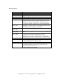
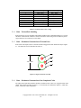
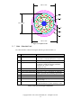
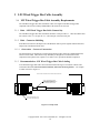
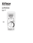
LXI Wired Trigger Bus Cable and Terminator Specifications Revision 2.00 May 18, 2011 Edition Copyright 2004 - 2011 LXI Consortium, Inc. All rights reserved. 1 1 OVERVIEW ..................................................................................................................................... 6 1.1 PURPOSE AND SCOPE ................................................................................................................... 7 1.2 DEFINITION OF TERMS ................................................................................................................. 7 1.3 LXI WIRED TRIGGER BUS CABLE AND TERMINATOR CONFORMANCE REQUIREMENTS.................. 8 1.3.1 Rule – Conformance Requirements ..................................................................................... 8 2 CABLE REQUIREMENTS ............................................................................................................. 9 2.1 CABLE MECHANICAL REQUIREMENTS .......................................................................................... 9 2.1.1 Rule – Outer Jacket Material and Thickness ........................................................................ 9 2.1.2 Rule – Twisted Pair Wire Diameter and Insulation .............................................................. 9 2.1.3 Rule – Twisted Pair Wire Color Coding............................................................................... 9 2.1.4 Rule – Twisted Pair Shielding ........................................................................................... 10 2.1.5 Rule – Mechanical Construction of Twisted Pairs .............................................................. 10 2.1.6 Rule – Mechanical Construction of the Completed Cable .................................................. 10 2.1.7 Rule – Materials Used ....................................................................................................... 11 2.2 ELECTRICAL CHARACTERISTICS ................................................................................................. 12 2.2.1 Rule – Electrical Characteristics ........................................................................................ 12 2.2.2 Minimum Pulse Width in Driven Mode and Wired-Of Modes ........................................... 12 2.2.3 Testing Electrical Requirements ........................................................................................ 12 3 LXI WIRED TRIGGER BUS CABLE ASSEMBLY .................................................................... 13 3.1 LXI WIRED TRIGGER BUS CABLE ASSEMBLY REQUIREMENTS.................................................... 13 3.1.1 Rule – LXI Wired Trigger Bus Cable Connectivity............................................................ 13 3.1.2 Rule – Connector Shielding ............................................................................................... 13 3.1.3 Recommendation - LXI Wired Trigger Bus Cable Labeling............................................... 13 3.2 LXI WIRED TRIGGER BUS CABLE ASSEMBLY TEST REQUIREMENTS ........................................... 15 3.2.1 Rule – LXI Wired Trigger Bus Cable Assembly Test Requirements .................................. 15 3.2.2 Rule – LXI Wired Trigger Bus Cable Assembly Wire Pairing ........................................... 15 3.2.3 Wire Pair Testing............................................................................................................... 15 4 LXI WIRED TRIGGER BUS TERMINATORS .......................................................................... 16 4.1 LXI WIRED TRIGGER BUS TERMINATOR MECHANICAL REQUIREMENTS ..................................... 16 4.1.1 Rule – LXI Wired Trigger Bus Terminator Physical Size................................................... 16 4.1.2 Recommendation – EMI Shielding .................................................................................... 16 4.1.3 Recommendation – Labeling ............................................................................................. 16 4.2 LXI WIRED TRIGGER BUS TERMINATOR ELECTRICAL REQUIREMENTS ....................................... 17 4.2.1 Rule – Termination Lengths .............................................................................................. 17 4.2.2 LXI Wired Trigger Bus Termination (informative) ............................................................ 17 4.2.3 LXI Wired Trigger Bus Terminator Testing ....................................................................... 17 APPENDIX A. GLOSSARY OF TERMS ............................................................................................ 19 APPENDIX B. RECOMMENDED ELECTRICAL TESTING .......................................................... 20 APPENDIX C. RECOMMENDED WIRE PAIR TESTING............................................................... 24 APPENDIX D. LXI WIRED TRIGGER BUS TERMINATOR TESTING ........................................ 28 Notice of Rights All rights reserved. This document is the property of the LXI Consortium. It may be reproduced, unaltered, in whole or in part, provided the LXI copyright notice is retained on every document page. Copyright 2004 - 2011 LXI Consortium, Inc. All rights reserved. 2 Notice of Liability The information contained in this document is subject to change without notice. “Preliminary” releases are for specification development and proof-of-concept testing and may not reflect the final “Released” specification. The LXI Consortium, Inc. makes no warranty of any kind with regard to this material, including but not limited to, the implied warranties of merchantability and fitness for a particular purpose. The LXI Consortium, Inc. shall not be liable for errors or omissions contained herein or for incidental or consequential damages in connection with the furnishing, performance, or use of this material. LXI Standards Documents are developed within the LXI Consortium and LXI Technical Working Groups sponsored by the LXI Consortium Board of Directors. The LXI Consortium develops its standards through a consensus development process modeled after the American National Standards Institute, which brings together volunteers representing varied viewpoints and interests to achieve the final product. Volunteers are not necessarily members of the Consortium and serve without compensation. While the LXI Consortium administers the process and establishes rules to promote fairness in the consensus development process, the LXI Consortium does not exhaustively evaluate, test, or verify the accuracy of any of the information contained in its standards. Use of an LXI Consortium Standard is voluntary. The LXI Consortium and its members disclaim liability for any personal injury, property or other damage, of any nature whatsoever, whether special, indirect, consequential, or compensatory, directly or indirectly resulting from the publication, use of, or reliance upon this, or any other LXI Consortium Standard document. The LXI Consortium does not warrant or represent the accuracy or content of the material contained herein, and expressly disclaims any express or implied warranty, including any implied warranty of merchantability or fitness for a specific purpose, or that the use of the material contained herein is free from patent infringement. LXI Consortium Standards documents are supplied “as is”. The existence of an LXI Consortium Standard does not imply that there are no other ways to produce, test, measure, purchase, market, or provide other goods and services related to the scope of the LXI Consortium Standard. Furthermore, the viewpoint expressed at the time a standard is approved and issued is subject to change brought about through developments in the state of the art and comments received from users of the standard. Every LXI Consortium Standard is subjected to review at least every five years for revision or reaffirmation. When a document is more than five years old and has not been reaffirmed, it is reasonable to conclude that its contents, although still of some value, do not wholly reflect the present state of the art. Users are cautioned to check to determine that they have the latest edition of any LXI Consortium Standard. In publishing and making this document available, the LXI Consortium is not suggesting or rendering professional or other services for, or on behalf of, any person or entity. Nor is the LXI Consortium undertaking to perform any duty owed by any other person or entity to another. Any person utilizing this, and any other LXI Consortium Standards document, should rely upon the advice of a competent professional in determining the exercise of reasonable care in any given circumstances. This specification is the property of the LXI Consortium, a Delaware 501c3 corporation, for the use of its members. Interpretations Occasionally questions may arise regarding the meaning of portions of standards as they relate to specific applications. When the need for interpretations is brought to the attention of LXI Consortium, the Consortium will initiate action to prepare appropriate responses. Since LXI Consortium Standards represent a consensus of concerned interests, it is important to ensure that any interpretation has also received the concurrence of a balance of interests. For this reason, LXI Consortium and the members of its working groups are not able to provide an instant response to interpretation requests except in those Copyright 2004 - 2011 LXI Consortium, Inc. All rights reserved. 3 cases where the matter has previously received formal consideration. Requests for interpretations of this standard must be sent to [email protected] using the form “Request for Interpretation of an LXI Standard Document” found on the LXI Consortium’s Web site: http://www.lxistandard.org Legal Issues, Trademarks, Patents, and Licensing Policies. These items are addressed specifically in the document “LXI Consortium Trademark, Patent, and Licensing Policies” found on the LXI Consortium’s Web site: http://www.lxistandard.org . Conformance The LXI Consortium draws attention to the document “LXI Consortium Policy for Certifying Conformance to LXI Consortium Standards” found on the LXI Consortium’s Web site: http://www.lxistandard.org . That document specifies the procedures that must be followed to claim conformance with this standard. Comments for Revision Comments for revision of LXI Consortium Standards are welcome from any interested party, regardless of membership affiliation with LXI Consortium. Suggestions for changes in documents should be in the form of a proposed change of text, together with appropriate supporting comments. Comments on standards should be addressed to: Bob Helsel Executive Director LXI Consortium PO Box 1016 Niwot, CO 80544-1016 303-652-2571 Office - LXI 303-579-2636 Mobile 303-652-1444 Fax [email protected] [email protected] LXI is a registered trademark of the LXI Consortium Copyright 2004 - 2011 LXI Consortium, Inc. All rights reserved. 4 Revision history: Revision 1.01 April 5, 2006 1.02 April 11, 2006 1.03 April 28, 2006 1.04 May 3, 2006 1.05 August 15, 2006 Editorial proposal Editorial proposal April 2, 2010 Editorial proposal April 5, 2010 Editorial proposal April 6, 2010 Editorial proposal May 18, 2010 2.00 Dec 16, 2010 2.0 0 Feb 28, 2011 2.00 Apr 11, 2011 2.00 May 18, 2011 Description Initial revision for review Apply Changes from Duaine Wood Apply Changes from David Owen Apply Changes from David Owen & Art Graafmans Add Cable Mis-pairing Test Revise front matter to be consistent with proposals for all standards. Minor revisions in wording of specifications. Formal definition of normative and informative. SUGGESTIONS for revising this document for consistency with other LXI standards. Incorporated rules, descriptions, and performance from LXI Standard 1.3 document specific to cable construction and system performance into this document. Conrad Proft Moved all test procedures to Appendices Changed all LXI Trigger Bus references to LXI Wired Trigger Bus Clarified how cable assemblies and terminators should adhere to compliance requirements by adding Rule in Section 1. Moved Figure 3.1 closer to referenced section. Changed the labeling of cable assemblies and terminators to recommendations. Version changes for review by LXI Consortium Updated copyright dates and LXI Device Specification 2011. Updated publication date for May 18, 2011 Corrected TOC issues due to Word revisions. Now 2007 docx file Final version after vote passed on 5/9/2011: - Changed file name to LXI Wired Trigger Bus Cable and Terminator Specifications rev 2.0 - Removed draft notes on title page Copyright 2004 - 2011 LXI Consortium, Inc. All rights reserved. 5 1 Overview The LXI Device Wired Trigger Bus implements a cabling system to interconnect multiple LXI Devices. The physical interface builds upon the TIA/EIA-889 Multipoint Low Voltage Differential Signaling (M-LVDS) standard. This standard uses differential current driven signals to exchange data between semiconductor devices. Each LXI Device supporting the LXI Wired Trigger Bus has a minimum of two Trigger Bus connectors. This provides a pass-through connection of the bus by routing signals through each participating instrument. A termination device is required at the end of each LXI Wired Trigger Bus connection segment, provided by the LXI Wired Trigger Bus Terminator. The terminator attaches to the second connector at each segment end, as seen in Figure 1.1. Figure 1.1 Configuration of LXI Devices using the LXI Wired Trigger Bus The LXI Wired Trigger Bus provides eight physically independent trigger channels, matching the number of logical channels provided by the LXI Event Message mechanism in the LXI standard. The LXI Wired Trigger Bus designates LXI0 to LXI7, while the LXI Event Message designates identifiers LAN0 to LAN7. Trigger events made through the LXI Wired Trigger Bus or the LXI Event Message trigger system are interchangeable, since the trigger model is consistent in each mode of operation. There are important differences in performance between the LXI Wired Trigger Bus and LXI Event Messages. LXI Event Messages are LAN-based and depend upon the LAN driver, LAN speed, software interrupts, and processor speed. The LXI Wired Trigger Bus is a dedicated bus interface with the following characteristics: o o o Hardware delays on the bus cables and associated routing logic dominate the trigger delay between an event and the initiation of an action at another node LXI Devices connect the trigger bus signals as directly as possible from the interface to the hardware performing the task. Once set up there is virtually no software or firmware related delays in reaction times. The LXI Wired Trigger Bus exhibits both low trigger delay and low trigger jitter and performance levels which are not achieved through the LAN based trigger mechanisms. In addition to supporting high performance trigger operations, the trigger bus can also be used to exchange clock signals or other data signals between LXI Devices. Copyright 2004 - 2011 LXI Consortium, Inc. All rights reserved. 6 1.1 Purpose and Scope This document specifies the requirements to construct LXI Wired Trigger Bus Cable assemblies. It defines the mechanical construction and the electrical characteristics and expected performance of the cable. The Standard also provides construction details for the completed LXI Wired Trigger Bus cables and LXI Wired Trigger Bus termination blocks. In addition, it discusses other interconnect methods such as LXI Wired Trigger Bus Adapters and Star Hub devices. This document focuses on the interconnection between LXI Devices that implement the LXI Wired Trigger Bus. Device specific requirements can found in the LXI Standard for LXI Devices. Properly functioning interconnect cables are required by LXI Devices to comply with their LXI triggering requirements. 1.2 Definition of Terms This document contains both normative and informative material. Unless otherwise stated the material in this document shall be considered normative. NORMATIVE: Normative material shall be considered in determining whether a product is conformant to this standard. Any section or subsection designated as a RULE or PERMISSION is normative. INFORMATIVE: Informative material is explanatory and is not considered in determining the conformance of a product supporting this standard. Any section or subsection designated as RECOMMENDATION or OBSERVATION is informative. Unless otherwise noted, examples are informative. RULE: Rules SHALL be followed to ensure compatibility for products supporting the LXI Wired Trigger Bus. A rule is characterized by the use of the words SHALL and SHALL NOT. These words are not used for any other purpose other than stating rules. RECOMMENDATION: Recommendations consist of advice to implementers that will affect the usability of the final device. Discussions of particular hardware to enhance throughput would fall under a recommendation. These recommendations should be followed to avoid problems and to obtain optimum performance. PERMISSION: Permissions are included to clarify the areas of the specification that are not specifically prohibited. Permissions reassure the reader that a certain approach is acceptable and will cause no problems. The word MAY is reserved for indicating permissions. OBSERVATION: Observations spell out implications of rules and bring attention to things that might otherwise be overlooked. They also give the rationale behind certain rules, so that the reader understands why the rule must be followed. Any text that appears without heading should be considered as description of the specification. Copyright 2004 - 2011 LXI Consortium, Inc. All rights reserved. 7 1.3 LXI Wired Trigger Bus Cable and Terminator Conformance Requirements The document “LXI Consortium Policy for Certifying Conformance to LXI Consortium Standards” gives specific requirements on conformance certification. Refer to Section 2 and Section 3 of that document for further information. 1.3.1 Rule – Conformance Requirements Cable assemblies shall implement and conform to all the rules in Sections 2 and 3 of this document. Terminators shall implement and conform to all the rules in Section 4 of this document. Both cable assemblies and terminators can be marked as outlined in those respective sections. Copyright 2004 - 2011 LXI Consortium, Inc. All rights reserved. 8 2 Cable Requirements Cable Mechanical Requirements 2.1 The LXI Wired Trigger Bus cable consists of eight twisted pairs. Each twisted pair is individually shielded with a wrap and a drain wire. The eight twisted pair sub assemblies are combined with a filler and wrapped with an outer shield covered with a separator. 2.1.1 Rule – Outer Jacket Material and Thickness The outer jacket should be a nominal 30 mil thick, pressured PVC construction rated for 80ºC and 30 V. The outer jacket should have a minimum thickness of 24 mil per AWM style 2502. The quality of the cable affects its ability to handle the stress of cable routine 2.1.1.1 Observation – Outer Jacket Color The outer jacket color is not specified which allows each manufacture to construct cable assemblies which conform to its own corporate color schemes and standards. 2.1.2 Rule – Twisted Pair Wire Diameter and Insulation Each twisted pair of wires should consist of two 26 AWG silver plated copper stranded wires. Each wire should be insulated with 14 mil nominal, 12 mil minimum cellular polyethylene rated for 80ºC 30 V. The nominal outer diameter of the insulation is 0.048” ± 0.002”. Constructing the cable in this manner should achieve good signal integrity and performance. 2.1.2.1 Observation A minimum 26 AWG copper wire with a surface conductivity equal to or better than silver is required to achieve the necessary system bandwidth. 2.1.3 Rule – Twisted Pair Wire Color Coding The wires used to construct the eight twisted pairs shall be color coded such that each wire is uniquely identifiable. 2.1.3.1 Recommendation – Twisted Pair Wire Color Coding It is recommended that the twisted pairs of the LXI Wired Trigger Bus cable be color coded according to Table 2.1. 2.1.3.2 Permission – Twisted Pair Wire Color Coding Since color coding does not affect electrical connectivity or performance of the wires, any other suitable color coding scheme may be used so long as each twisted pair and connection can be uniquely identified. Copyright 2004 - 2011 LXI Consortium, Inc. All rights reserved. 9 Pair Number P Color / Stripe N Color / Stripe 1 2 3 4 5 6 7 8 White / Blue White / Orange White / Green White / Brown White / Gray Red / Blue Red / Orange Red / Green Blue / White Orange / White Green / White Brown / White Gray / White Blue / Red Orange / Red Green / Red Table 2.1 Twisted Pair Wire Color Coding 2.1.4 Rule – Twisted Pair Shielding Each twisted pair of wires should be individually shielded with an Aluminum/Mylar foil. The foil should be wound with the conductive surface towards the inside along with a 28 AWG tin plated copper drain wire for connectivity to the shield. 2.1.5 Rule – Mechanical Construction of Twisted Pairs Each of the twisted pairs used to construct the Wired Trigger Bus cable should be built per Figure 2.1. The materials used are identified in Table 2.2 A B .100 +/-.005" C D Figure 2.1 Single Twisted Pair Assembly 2.1.6 Rule – Mechanical Construction of the Completed Cable The eight twisted pair subassemblies should be combined with a center core, wrapped with an outer shield, and jacketed according to Figure 2.2. The materials are identified in Table 2.2, which also locates each of the cable components. Copyright 2004 - 2011 LXI Consortium, Inc. All rights reserved. 10 .285 +/-.010" E F .275 +/-.010" G H I .355 +/-.010" Figure 2.2 Completed Cable 2.1.7 Rule – Materials Used The cable should be constructed using the material types listed in Table 2.2. Item Type Material A Signal Wire Conductor B C Drain Wire Signal Wire Insulation D Twisted Pair Shield 26 AWG Silver Plated Copper, Stranded 7 x 0.0063”, Concentric OD 0.019” ± 0.001” 28 AWG Tin Plated Copper, Stranded 7 x 0.005” 14 mil cellular polyethylene 80C 30V, 12 mil min. cellular polyethylene insulation Nominal O.D. 0.048” ± 0.002” AWM style 1589 Aluminum/Mylar shield. Wound foil side in. E Twisted Pair Subassembly F G H Core Filler Separator Outer Shield I Outer Jacket See Figure 2.1 For Construction. No particular pitch is specified due to shielding requirements. Polyethylene Filler. Opaque Mylar. 38 AWG Tin/Copper spiral serve to 85% coverage. 30 mil pressured PVC jacket 80C 30 V. 24 mil minimum PVC jacket AWM style 2502. Table 2.2 Materials used and figure identification Copyright 2004 - 2011 LXI Consortium, Inc. All rights reserved. 11 2.1.7.1 Permission – Use Of Alternate Materials Other materials may be used so long as the cable meets all the specified electrical, mechanical, and safety requirements specified in this document. 2.1.7.2 Observation – Use of Alternate Materials The materials used in the construction of the cable directly affect the electrical performance, mechanical performance, and safety approvals. 2.2 Electrical Characteristics A cable constructed to the standard should have the characteristics described in Table 2.3 Nom. Diff. Characteristic Impedance Nom. Inductance @ 10 kHz Nom. Capacitance – Conductor To Conductor @ 10 kHz Nom. Capacitance – Conductor To Other Conductor & Shield @ 10 kHz Nom. Velocity of Propagation Nom. Conductor DC Resistance @ 20C Nom. Outer Shield DC Resistance @ 20C Max. Operating Voltage 100 ohms (+10 ohms, -15 ohms) 0.47 uH/meter 41.0 pF/meter 65.6 pF/meter 74% 14.57 ohms / 100 meters 1.7 ohms / 100 meters 30 V RMS Table 2.3 Electrical Performance Characteristics 2.2.1 Rule – Electrical Characteristics If a cable is constructed using alternate materials from those identified in Table 2.2, then the resulting cable should conform to the specifications listed in Table 2.3 2.2.2 Minimum Pulse Width in Driven Mode and Wired-Of Modes When constructing cables in accordance with these specifications, the minimum pulse width of LXI Wired Trigger Bus signals transmitted in Driven Mode is 10ns for connection segments of 10 meters or less and 20 ns on connection segments of 20 meters or less. Similarly, the minimum pulse width of LXI Wired Trigger Bus signals transmitted in Wired-Or Mode is 20ns for connection segments of 10 meters or less and 40 ns on connection segments of 20 meters or less. 2.2.3 Testing Electrical Requirements Appendix B gives recommendations for testing the various electrical requirements in building an LXI Wired Trigger Bus cable assembly. Copyright 2004 - 2011 LXI Consortium, Inc. All rights reserved. 12 3 LXI Wired Trigger Bus Cable Assembly LXI Wired Trigger Bus Cable Assembly Requirements 3.1 The LXI Wired Trigger Bus cable assemblies consist of a length of LXI Wired Trigger Bus compliant cable wired to industry standard Micro-D connectors at each end. 3.1.1 Rule – LXI Wired Trigger Bus Cable Connectivity The LXI Wired Trigger Bus cable assemblies should be wired per Table 3.1. Cable assemblies must not connect to the +3.3 volt pin, the +3.3 volt return pin, or the Reserved pins. 3.1.2 Rule – Connector Shielding Each Micro-D connector should provide a shielded back shell to protect against radiated emissions and provide a mechanical strain relief. 3.1.2.1 Observation – Connector Construction The back shell may be designed as a metal casting which provides strain relief, EMI management, and an exterior finish. The connector may alternately be designed as a formed sheet metal component with a plastic boot or plastic over-mold cover to provide the finished component. 3.1.3 Recommendation - LXI Wired Trigger Bus Cable Labeling An LXI Wired Trigger Bus cable can be labeled with the LXI logo, in accordance with the LXI Consortium document LXI Consortium Trademark, Patent and Licensing Policies . An example of which is shown in Figure 3.1. CABLE LENGTH SPECIFIED FROM THESE POINTS IN METERS LABEL USING SHRINK TUBING OR EQUIVALENT. INCLUDE CABLE LENGTH, MANUFACTURE'S PART NUMBER AND REVISION. 2X CIRCUIT ASSEMBLY CORP. P/N: U712002 OR EQUIVALENT Figure 3.1 Example Cable Copyright 2004 - 2011 LXI Consortium, Inc. All rights reserved. 13 CONN SIGNAL NAME (Informative, see LXI Standard for LXI Devices section 5) 1 +3.3V 2 +3.3V RETURN 3 LXI1p 4 LXI1n 5 GND 6 LXI3p 7 LXI3n 8 GND 9 LXI5p 10 LXI5n 11 RESERVED 12 LXI7p 13 LXI7n 14 LXI0p 15 LXI0n 16 RESERVED 17 LXI2p 18 LXI2n 19 GND 20 LXI4p 21 LXI4n 22 GND 23 LXI6p 24 LXI6n 25 RESERVED P1 PIN WIRE COLOR P2 PIN 1 2 3 4 5 6 7 8 9 10 11 12 13 14 15 16 17 18 19 20 21 22 23 24 25 N/C N/C 1 2 3 4 5 6 7 8 9 10 11 12 13 14 15 16 17 18 19 20 21 22 23 24 25 26 26 CHASSIS N/C N/C N/C 26 NOTES Paired with pin 4 Paired with pin 3 Drains from conn 3-4 & 6-7 Paired with pin 7 Paired with pin 6 Drains from conn 9-10 & 12-13 Paired with pin 10 Paired with pin 9 Paired with pin 13 Paired with pin 12 Paired with pin 15 Paired with pin 14 Paired with pin 18 Paired with pin 17 Drains from conn 14-15 & 17-18 Paired with pin 21 Paired with pin 20 Drains from conn 20-21 & 23-24 Paired with pin 24 Paired with pin 23 Outer shield wires – attach to the connector shell. Table 3.1 LXI Wired Trigger Bus Wiring Copyright 2004 - 2011 LXI Consortium, Inc. All rights reserved. 14 LXI Wired Trigger Bus Cable Assembly Test Requirements 3.2 3.2.1 Rule – LXI Wired Trigger Bus Cable Assembly Test Requirements The completed LXI Wired Trigger Bus Cable assembly should be tested for proper continuity and short circuits. This may be accomplished using standard cable test equipment and fixtures. 3.2.2 Rule – LXI Wired Trigger Bus Cable Assembly Wire Pairing The completed LXI Wired Trigger Bus Cable assembly should be compliance tested for proper pairing of the differential signals. 3.2.2.1 Observation – Cable Assembly Wire Pairing The testing of wire pairing is required to assure that the assembly methods are correct. Wire pair testing as a part of production test is expected. Once proper assembly methods are established, and demonstrated by the compliance test, no production test for wire pairing is required. Note that continuity testing assures that all signals are connected and not cross-wire; however, it does not assure that each differential signal is correctly paired in the cable assembly. 3.2.3 Wire Pair Testing Appendix C gives recommendations for wire pair testing. Copyright 2004 - 2011 LXI Consortium, Inc. All rights reserved. 15 4 LXI Wired Trigger Bus Terminators 4.1 LXI Wired Trigger Bus Terminator Mechanical Requirements An LXI Wired Trigger Bus Terminator consists of either a 25 pin Micro-D style plug connector which mates to an LXI Device, or a module with a 25 pin Micro-D style jack which mates to an LXI Wired Trigger Bus Cable Assembly. Either device is wired to a printed circuit board which supports the required termination components, and may include additional components such as bus monitoring circuitry. 4.1.1 Rule – LXI Wired Trigger Bus Terminator Physical Size The completed LXI Terminator should comply with all the requirements (both electrical and mechanical) of a 25 pin Micro-D style plug. An LXI Terminator implemented using a plug connector should be no larger than a standard connector back shell. 4.1.2 Recommendation – EMI Shielding The shielded terminator connected to the metal shell of the connector protects from EMI radiation. The terminator device should provide standard jack screws to secure it to its mating connector and guarantee connectivity. See figure 4.1 for a typical implementation. 4.1.3 Recommendation – Labeling The terminator can be externally labeled to indicate that the device is an LXI Wired Trigger Bus Terminator, and to which revision of this specification it complies. Figure 5.1 Figure 4.1 Example LXI Wired Trigger Bus Terminators Copyright 2004 - 2011 LXI Consortium, Inc. All rights reserved. 16 LXI Wired Trigger Bus Terminator Electrical Requirements 4.2 Each end of an LXI Wired Trigger Bus segment should be terminated using an LXI Wired Trigger Bus Terminator Block (except for devices which have a single trigger bus port and provide the termination function internally). The Terminator Block provides a nominal 100 ohm differential termination to each of the eight LXI Wired Trigger Bus channels and an AC common mode termination. This is accomplished by wiring two 50 ohm resistors in series and connecting a 0.01uF ceramic capacitor from the center tap of the resistors to ground. See Figure 4.2 for a schematic representation of the LXI Wired Trigger Bus Terminator Block. 4.2.1 Rule – Termination Lengths The connection lengths to the termination resistors and capacitors shall be kept to a minimum to assure a high quality termination. If the connection from the terminator’s connector to the terminating resistors is greater than 5mm, the connections must be designed to provide a 100 ohm differential impedance up to the termination network. 4.2.1.1 Example – Terminator Layout Figure 4.3 shows a typical board layout for an LXI Wired Trigger Bus Terminator. The Printed Circuit Board is 0.700” by 0.500” in size, has two layers, and is constructed of 0.031” thick FR-4 type epoxy-glass material. The termination resistors are 0402 size thick film surface mount type, and the capacitors are 0603 size X7R dielectric surface mount type. The top layer is represented in red, and the bottom layer is represented in green. 4.2.2 LXI Wired Trigger Bus Termination (informative) The LXI Wired Trigger Bus uses termination connector blocks installed at both ends of a connection segment, as shown in Figure 1.1. Each individual channel is terminated at each end by two 50-ohm (±5 %) resistors connected in series between the positive (A) and negative (B) signal wires, and a 0.01μF capacitor to ground connected to the node between the resistors, as shown in Figure 4.2. The resistor values are matched to within ±2% 4.2.3 LXI Wired Trigger Bus Terminator Testing Appendix D shows recommended testing procedures for the completed LXI Wired Trigger Bus Terminator Copyright 2004 - 2011 LXI Consortium, Inc. All rights reserved. 17 LXI0P C1 0.01uF R1 49.9 LXI4P C5 R2 49.9 0.01uF R9 49.9 R10 49.9 LXI0N LXI4N LXI1P C2 R3 49.9 LXI5P C6 R11 49.9 P1 +3.3V +3.3V RTN LXI1P LXI1N 0.01uF 0.01uF R4 49.9 R12 49.9 LXI1N LXI3P LXI3N LXI5N LXI5P LXI5N RESERVED LXI7P LXI7N LXI0P LXI0N LXI2P C3 R5 49.9 LXI6P C7 R13 49.9 RESERVED LXI2P LXI2N LXI4P LXI4N LXI6P LXI6N 0.01uF C4 0.01uF R6 49.9 0.01uF RESERVED R14 49.9 LXI2N LXI6N LXI3P LXI7P R7 49.9 C8 R8 49.9 0.01uF LXI3N R15 49.9 R16 49.9 LXI7N Figure 4.2 Termination Requirements Figure 4.3 Example termination pads Copyright 2004 - 2011 LXI Consortium, Inc. All rights reserved. 18 1 2 3 4 5 6 7 8 9 10 11 12 13 14 15 16 17 18 19 20 21 22 23 24 25 1 2 3 4 5 6 7 8 9 10 11 12 13 14 15 16 17 18 19 20 21 22 23 24 25 Appendix A. Glossary of Terms AWG American Wire Gage. Measure of wire diameter. AWM Appliance Wiring Material. A UL designation for a type of wire. CSA Canadian Standards Association. LVDS Low-Voltage Differential Signaling. LXI LAN Extension for Instrumentation. LXI Device An instrument or other device which conforms to the LXI standard. Micro D Connector Connector style the commercial version of which is specified to be use on the WTB in the LXI Standard. This connector is compatible with the high reliability version of the Micro-D connector commonly used in military applications. M-LVDS Multipoint Low-Voltage Differential Signaling conforming to TIA/EIA-899 standard. UL Underwriters Laboratory. TDR Time Domain Reflectometer. A method of measuring impedance and defects in a transmission by propagating a pulse down the line and observing the reflections as a function of time (distance down the line). Terminator Device specified in the LXI Standard that terminates the differential pair transmission line used on the WTB. WTB Wired Trigger Bus. Copyright 2004 - 2011 LXI Consortium, Inc. All rights reserved. 19 Appendix B. Recommended Electrical Testing This section describes the tests a cable manufacturer can use to demonstrate compliance of a sample cable to the LXI Wired Trigger Bus Cable Specification. A supplier of LXI Wired Trigger Bus Cable Assemblies should ensure that the cable used in constructing a Cable Assembly has been sample tested. Characteristic Impedance The characteristic impedance of each twisted shielded pair should be measured using a Differential TDR (Time Domain Reflectometer) Characteristic Impedance Test Method A 100cm sample of the cable is prepared for test by removing 3.5cm of the outer insulation material, gathering up the outer shield wires and twisting them together at one end only. A twisted pair is exposed by removing 6mm of the shielding foil, thereby exposing two insulated wires and a bare drain wire. The insulated wires are stripped back 2mm to expose the conductors. Two coaxial cable assemblies are prepared using 15cm of 50 ohm 0.085” formable coaxial cable with SMA type connectors on one end. The other end of each cable assembly has the braid and dielectric stripped back 2mm. The stripped end of the two coaxial cables are laid side by side and the outer braids are soldered together over a length of approximately 6cm from the stripped ends. The test cable is then attached to the coaxial cables, with the drain wire attached to the coaxial cables’ braids, and with each of the twisted pair wires connected to one of the two center conductors. See Figures B.1 and B.1 for details. The two SMA connectors are attached to the TDR’s test ports, and the TDR is adjusted to display the reflected waveform from the initial edge to the end of the cable (where the impedance goes toward infinity). The TDR should then be adjusted to measure the differential impedance at approximately 6cm into the test cable to avoid erroneous readings due to the transition areas where the test cable assembly attaches to the cable under test. Record the measured impedance and confirm that it conforms to the requirements stated in Table 2.3. Figure B.1 Copyright 2004 - 2011 LXI Consortium, Inc. All rights reserved. 20 Figure B.2 Inductance The inductance of the signal conductors verified using an LCR bridge. Inductance Test Method A 1.025 meter sample of cable is prepared for testing by striping back 5mm of outer jacket and cutting away the outer shield wires. A signal pair is selected, the wires are exposed by removing their inner shield foil, and are stripped back 3mm. The two signal wires along with the shield drain wire are joined together and soldered. At the other end of the cable, 25mm of outer jacket is stripped away and the outer shield wires are cut away. Separate the eight twisted pairs and select the same pair as previously selected. Remove 25mm of its inner shield, and strip back the two signal wires 5mm. One of the two signal connections is connected to the shield drain wire. The LCR bridge is set to measure inductance at a test frequency of 10KHz and the cable sample is connected. Connect the wire with the drain wire to the high side of the LCR bridge, and the other wire to the low side (connecting the drain wire to the high side reduces noise pickup). Record the inductance measured. Copyright 2004 - 2011 LXI Consortium, Inc. All rights reserved. 21 Capacitance The capacitance of the signal connections verified using an LCR bridge. Capacitance Test Method A 1.025 meter sample of cable is prepared for testing by striping back 25mm of outer jacket and cutting away the outer shield wires. Separate the eight twisted pairs and select the same pair as previously selected. Remove 25mm of its inner shield, and strip back the two signal wires 5mm. The LCR bridge is set to measure capacitance at a test frequency of 10KHz and the cable sample is connected. Connect one of the signal wires to the high side of the LCR bridge, and the other signal wire to the low side. Record the conductor to conductor capacitance measured. Remove the signal wire connected to the high side of the LCR bridge and connect the shield drain wire in its place (connecting the drain wire to the high side reduces noise pickup). Record the conductor to shield capacitance. Velocity Of Propagation The velocity of propagation is measured using the same equipment and setup used to measure characteristic impedance. Velocity of Propagation Test Method The test cable assembly used in Figures B.1 and B.2 are connected to the differential TDR for measurement. The TDR is adjusted so that the small bump in impedance where the fixture cables attach to the test cable is visible as well as the end of the cable where the impedance goes toward infinity. Using the cursors on the TDR, measure the time from the center of the impedance bump to the point where the impedance goes toward infinity. This is the time delay through 1 meter of test cable. Note that the test cable must be accurately measured and cut to within 5mm of 1 meter. The velocity of propagation is calculated by dividing the velocity of light by one half the measured delay (the measured delay is a round trip time up and down the test cable) times 100 percent. Velocity of Propagation = 3.336nS 100% 1 T nSM M 2 Record the measured velocity of propagation and confirm that it conforms to the requirements stated in Table 2.3. DC Resistance The DC resistance measurement is made using a four-wire method. A digital multimeter which can resolve a minimum of 10 milliohms is required. DC Resistance Test Method A 20 meter sample of the cable is prepared for test by removing 2.5cm of the outer insulation material, gathering up the outer shield wires and twisting them together at both ends. A single insulated wire is isolated from a twisted pair at both ends, and its insulation is stripped back 3mm on each end. Wire the DMM to two ends of the sample cable using the four-wire measurement Copyright 2004 - 2011 LXI Consortium, Inc. All rights reserved. 22 technique (refer to the DMM’s user manual for details). Record the measured resistance and confirm that it conforms to the requirements stated in Table 2.3 for the conductor DC resistance. Wire the DMM to the two ends of the outer shield wires (that were gathered up in the previous step) of the same 20 meter sample. Measure the resistance of the shield wires using the four-wire measurement technique. Record the measured resistance and confirm that it conforms to the requirements stated in Table 2.3 for the outer shield DC resistance. Copyright 2004 - 2011 LXI Consortium, Inc. All rights reserved. 23 Appendix C. Recommended Wire Pair Testing An LXI Wired Trigger Bus cable is tested for proper signal pairing by testing for the presence of cross-talk to alternate channels. Since each pair is individually shielded, a properly constructed cable assembly should show very low levels of cross-talk to alternate channels. A cable assembly, which has one or more connections miss-paired, will display a notable amount of cross-talk to an alternate channel, revealing the miss-wired connection. Wired Pairing Test Setup The wired pairing test setup consists of a pulse generator (Tektronix AFG3252 or equivalent), an LXI Wired Trigger Bus Adapter (Pickering Interfaces P/N 60-982 or equivalent), an LXI Wired Trigger Bus Probe (Pickering Interfaces P/N 60-981 or equivalent), an LXI Wired Trigger Bus Terminator (Circuit Assembly Corporation P/N U712003 or equivalent), An Oscilloscope with a minimum 1GHz bandwidth (Tektronix DPO4104 or equivalent), and the LXI Wired Trigger Bus cable assembly under test. Figure C.1 shows the basic test setup. The pulse generator is wired to the LXI Wired Trigger Bus Adapter such that it can drive any one of the eight LXI Trigger channels. The LXI Wired Trigger Bus Adapter directly drives the Cable Under Test and provides the terminations required at that end of the cable. The other end of the Cable Under Test is connected to the LXI Wired Trigger Bus Probe. The LXI Wired Trigger Bus Probe has a through type connection, so it requires an external terminator. The oscilloscope monitors the outputs of the Probe and two channels are required. One channel monitors the driven channel and provides a trigger source for the Oscilloscope, and the other channel is used to check for cross-talk to the other LXI Wired Trigger Bus signal pairs. PULSE GENERATOR LXI TRIGGER BUS TERMINATOR CABLE UNDER TEST LXI TRIGGER BUS ADAPTER LXI TRIGGER BUS PROBE Figure C.1 Wired pairing test setup The pulse generator is set to provide a 10 KHz square wave output with an amplitude appropriate to drive the LXI Wired Trigger Bus Adapter (see the user’s manuals for details). The LXI Wired Trigger Bus Adapter is configured for driven mode output on all channels, and the pulse generator is connected to drive channel LXI0. The other Channels are set to a fixed low state. The oscilloscope is setup with one channel set to 200mV/division, 50 ohms, DC coupled input and is connected to the positive half of the driven channel (beginning with LXI0p). The second channel of the oscilloscope is set to 20mV/division, 1Mohm, AC coupled input. The second channel input is used to check the un-driven cable connections for cross-talk. The oscilloscope’s horizontal time-base is set for 200nS/division and the oscilloscope’s acquisition mode is set to average 32 Copyright 2004 - 2011 LXI Consortium, Inc. All rights reserved. 24 readings. Note that without averaging multiple readings, the cross-talk signal will be largely buried in noise. Wired Pairing Test Procedure The test for miss-wired pairs is preformed using a process of elimination technique. The pulse generator is first connected to drive LXI0 via the LXI Wired Trigger Bus Adapter. The first channel of the oscilloscope is connected to the positive output of the LXI Wired Trigger Bus Probe, and the second channel is connected to both the positive and negative outputs of LXI1 through LXI7, one output at a time. See Figures C.2 through C.5 for examples of typical oscilloscope displays for 0.5meters and 20meters in length showing both passing and failing conditions. Each output is checked for a cross-talk condition, and if any output displays this characteristic, the cable assembly shall fail this test. Once channel LXI0 has been tested, the pulse generator output is moved to drive LXI1, and the positive and negative outputs of the LXI Wired Trigger Bus Probe for channels LXI2 through LXI7 are checked for cross-talk. LXI0 does not need to be checked, as it has already been confirmed to not have a cross-talk condition. This process is repeated until all LXI Wired Trigger Bus channels have been confirmed. A cable assembly which has passed this test along with the basic continuity test shall be confirmed compliant. Figure C.2 – 0.5 meter cable displaying no cross-talk Copyright 2004 - 2011 LXI Consortium, Inc. All rights reserved. 25 Figure C.3 – 0.5 meter cable displaying cross-talk Figure C.4 – 20 meter cable displaying no cross-talk Copyright 2004 - 2011 LXI Consortium, Inc. All rights reserved. 26 Figure C.5 – 20 meter displaying cross-talk. Copyright 2004 - 2011 LXI Consortium, Inc. All rights reserved. 27 Appendix D. LXI Wired Trigger Bus Terminator Testing LXI Wired Trigger Bus Terminator Test Method Using a precision ohm meter (such as the Keithley 2000 or equivalent), the resistance between each channel’s positive and negative connection is measured using the four wire resistance measuring technique. Verify that each channel measures 100 ohms +/- 5%. Using an LCR bridge (such as the Agilent 4263B or equivalent) set to measure capacitance and series resistance and operating at 10KHz, measure from each channel’s positive and negative connection to ground. Verify that each channel connection measures 0.01uF +/- 20% with 50 ohm +/- 5% series resistance. Verify that the series resistances measured for the positive and negative connection of each channel are within 2% of each other. Copyright 2004 - 2011 LXI Consortium, Inc. All rights reserved. 28


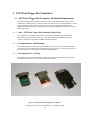
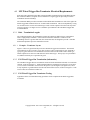
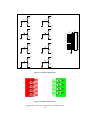


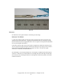


![[SOURce[1|2]]](http://vs1.manualzilla.com/store/data/005803287_1-72ff358839cd16ae2e8c94de56269657-150x150.png)