1
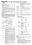
Varlogic NR6, NR12
Power factor controller
DB121630
User manual
3653491EN_01.indd 1
07/04/2009 14:24:10
Power Factor Controller NR6 / NR12
User manual
Table of Contents
1. General ..............................................................................................3
1.1 Safety .......................................................................................................... 3
1.2 Description ................................................................................................. 3
2. Installation ........................................................................................5
3. Display ..............................................................................................6
4. Start-up Procedure ...........................................................................6
5. Menu Operations ..............................................................................7
5.1 General ........................................................................................................ 7
5.2 Main Menu ................................................................................................... 9
5.3 Bank Pre-Configuration ........................................................................... 11
5.4 Commissioning ........................................................................................ 13
5.5 Auto Setup of Parameters ........................................................................ 14
5.6 Manual Setup of Parameters ................................................................... 15
5.7 Measurement Menu .................................................................................. 17
5.8 Parameter Update ..................................................................................... 18
5.9 Alarms Menu ............................................................................................. 19
5.10 Maintenance Menu ................................................................................. 21
6. Miscellaneous ................................................................................22
6.1 Stepping Programs .................................................................................. 22
6.2 Manual calculation of response value .................................................... 26
6.3 High Voltage use of NR6/NR12 ................................................................ 27
7. Glossary ..........................................................................................29
8. Technical specifications ................................................................32
2
3653491EN_01.indd 2
3653491EN_01.indd
07/04/2009 14:24:14
Power Factor Controller NR6 / NR12
User manual
1. General
1.1 Safety
The following precautions must be taken into account when installing and operating
the controller:
@ The installation of the controller must be performed by a qualified electrician.
@ Do not touch the connectors when the controller is energized, make sure that the
operating voltage is disconnected before touching any parts located on the rear
side of the controller.
@ Do not open a live current circuit, this may cause dangerous overvoltages. Always
short circuit the current transformer (CT) before replacing or removing the controller
installed in a bank.
@ Do not open the controller casing, there are no user serviceable parts inside.
For better understanding of the terminology used, please refer to the Glossary
(chapter 7) at the end of this manual.
DB121632
1.2 Description
Front view:
Legend
A
B
C
D
E
F
Display
Keys
Opening of door
Door
Alarm information
Mounting bracket for panel mounting installation
3653491EN_01.indd
3653491EN_01.indd 3
3
07/04/2009 14:24:14
DB121631
Power Factor Controller NR6 / NR12
User manual
Rear view:
Legend
Step output connectors
Specification label
Mounting bracket for panel mounting installation
Fixing spring for DIN-rail mounting
Current/voltage connection inputs
Fan and alarm outputs
DIN-rail mounting installation area
DB121633
G
H
I
J
K
L
M
Side view:
Legend
N
Screwdriver guide
See Chapter 8 for technical specifications.
4
3653491EN_01.indd 4
3653491EN_01.indd
07/04/2009 14:24:14
Power Factor Controller NR6 / NR12
User manual
2. Installation
The controller is designed for either panel (cut-out 138 x 138 mm) or DIN-rail
installation. It is locked to the rail by a screwdriver-operated fixing spring and to a
panel by a side fitting spring.
There are two ways of connecting the controller to the network:
⇒ (CT on the same line phase)
@ Voltage LN (Line – Neutral)
⇒ (CT on the third phase)
@ Voltage LL (Line – Line)
Incorrect connections can be automatically corrected by the controller when Auto
Setup is selected from the main menu.
DB121673
Caution: For use in HV network, look first at chapter 6.3.
Figure 1: Controller connections.
3653491EN_01.indd
3653491EN_01.indd 5
5
07/04/2009 14:24:14
Power Factor Controller NR6 / NR12
User manual
3. Display
DB121674
The controller is equipped with a backlighted LCD-display.
Figure 2: Display layout and symbols.
4. Start-up Procedure
Before connecting power, check the wiring of all controller terminals. Check
carefully for correct operating voltage. Selection of wrong voltage input can
permanently damage the controller.
After the first power switch-on, the controller will automatically ask for the language
setting of the menu.
6
3653491EN_01.indd 6
3653491EN_01.indd
07/04/2009 14:24:15
DB121675
Power Factor Controller NR6 / NR12
User manual
Figure 3: Language setting dialog.
5. Menu Operations
5.1 General
Navigation between different menu levels.
As a precaution against accidental use, the access of certain menus has been
protected by a keylock, which is a special sequence of keystrokes enabling the use
the particular menu item.
3653491EN_01.indd
3653491EN_01.indd 7
7
07/04/2009 14:24:15
DB121676
Power Factor Controller NR6 / NR12
User manual
Figure 4: General way of entering the menu with a keylock.
DB121677
Adjusting a value.
Figure 5: Adjusting a value.
DB121677
Special case: The wiring editor.
Figure 6: The wiring editor.
8
3653491EN_01.indd 8
3653491EN_01.indd
07/04/2009 14:24:15
Power Factor Controller NR6 / NR12
User manual
5.2 Main Menu
DB121678
The main menu contains all basic submenus required to set up and operate the
controller.
Which menu to choose ?
Figure 7: Required skills and menu selection.
If bank preconfiguration is properly done, commissioning does not require any
special skill.
3653491EN_01.indd
3653491EN_01.indd 9
9
07/04/2009 14:24:15
DB121679
Power Factor Controller NR6 / NR12
User manual
Figure 8:
Main menu.
10
3653491EN_01.indd 10
(1) Bank pre-configuration
When factory settings have not been changed, this menu
provides the bank builder the means of pre-configuring the bank
at the workshop. After pre-configuration, this menu topic is
replaced by
(2) Commissioning,
by which the controller is taken into service.
(3) Automatic setup of parameters
In the event that the controller has not been pre-configured, an
inexperienced user can automatically set up all the
characteristics of the bank and bring it into service.
(4) Manual setup of parameters
In the event that the controller has not been pre-configured, an
experienced user can manually set up all the characteristics of
the bank and bring it into service.
(5) Measurement
The measurement menu contains the most common
measurements taken from the network and provides some
information about the bank. This is a read-only menu.
(6) Parameter update
At any time, an experienced user can access the most common
operating parameters from this menu. Unlike the configuration
and setup sequences, this is a menu allowing a free and
unrestricted entry into all its items and should be used when an
occasional parameter access is needed.
(7) Alarm settings
To adjust status and parameters of alarms.
(8) Maintenance
The maintenance menu provides some useful information about
the usage of the bank, capacitors and contactors. Some
auxiliary settings and action have also been provided. This menu
is basically intended for use by the manufacturer’s maintenance
team.
3653491EN_01.indd
07/04/2009 14:24:15
Power Factor Controller NR6 / NR12
User manual
5.3 Bank Pre-Configuration
This menu item is a forced sequence, meaning that all items must be accessed
before the pre-configuration takes place.
NOTE:
Do not use of the Bank Pre-Configuration menu for HV network
applications.
The sequence can be interrupted by pressing
key.
See Glossary (chapter 7) for parameters definitions.
3653491EN_01.indd
3653491EN_01.indd 11
11
07/04/2009 14:24:15
DB121680
Power Factor Controller NR6 / NR12
User manual
Figure 9: Bank pre-configuration.
12
3653491EN_01.indd 12
3653491EN_01.indd
07/04/2009 14:24:16
Power Factor Controller NR6 / NR12
User manual
5.4 Commissioning
A pre-configured controller is put into service by this menu. The sequence contains
an automatic parameter verification to check that the manually entered parameters
agree with the network used.
DB121681
See Glossary (chapter 7) for parameter definitions.
NOTE:
Do not use of the Commissioning menu for HV network applications.
Figure 10: Commissioning.
What to do in case of error?
Error codes can help you to identify a problem and make corrections.
3653491EN_01.indd
3653491EN_01.indd 13
13
07/04/2009 14:24:16
Power Factor Controller NR6 / NR12
User manual
Code Meaning
Action to do
Unstable network: The controller is @ Enter the parameter settings
unable to operate due to excessive manually using Parameter Update
load variations on the network. CT
menu.
@ Rerun the commissioning sequence.
oversized.
Step size too small: The effect of the @ Check wiring, CT, condition of
1st step cannot be measured. CT
capacitor steps (1st step).
oversized, wrong wiring, inoperative
steps.
Sequence not found: Step ratio does @ Check the condition and sizes of
not match available step sequences. steps and contactors.
@ Check the condition and sizes of
Step size too large: The ratio of
measured step compared with the 1st steps and contactors.
step is too large. Step sequence
cannot be resolved.
Non-relevant autosetup process with @ Use manual setup to confirm or
this bank configuration.
correct the information obtained by
autosetup.
Reserved
to
Wiring verify error: Controller wiring @ Check the wiring of voltageand
not correct.
current inputs.
@ Check the Wiring setting from
Parameter Update menu.
Step count error: The Number of
@ Check the Number of Steps setting.
@ Check the number of steps in the
Steps setting is incorrect.
bank and the condition of steps.
Step sequence error: The step size @ Check Step Sequence setting
@ Check step sizes used in the bank
ratios differ from the selected step
sequence.
@ Check the response value used
C/K value error.
@ Check the size of 1st step in the bank
5.5 Auto Setup of Parameters
The auto setup sequence is intended for inexperienced users so they can
commission the bank with minimal prior knowledge. The user need only input three
of the most common parameters and then launch an automatic search for the other
parameters.
NOTE:
The use of Auto Setup of Parameters menu is forbidden on HV network
applications.
In the event of error, see the Commissioning Menu (chapter 5.4).
14
3653491EN_01.indd 14
3653491EN_01.indd
07/04/2009 14:24:16
DB121682
Power Factor Controller NR6 / NR12
User manual
Figure 11: Auto setup of parameters.
5.6 Manual Setup of Parameters
The manual setup sequence is intended for experienced users. There are nine
important parameters to input before the controller can be taken into service. This
sequence is completed by an automatic verification of the parameters entered
earlier in this sequence.
This menu item is a forced sequence, meaning that all items must be accessed
before the validation of the setup takes place.
key.
The sequence can be interrupted by pressing
See Glossary (chapter 7), for parameter definitions.
In case of error, refer to the Commissioning Menu, chapter 5.4.
3653491EN_01.indd
3653491EN_01.indd 15
15
07/04/2009 14:24:16
DB121683
Power Factor Controller NR6 / NR12
User manual
Figure 12: Manual setup of parameters.
16
3653491EN_01.indd 16
3653491EN_01.indd
07/04/2009 14:24:16
Power Factor Controller NR6 / NR12
User manual
5.7 Measurement Menu
DB121684
The measurement menu contains the most common measurements taken from the
network.
This is a read-only menu sequence.
Figure 13: Measurement menu.
3653491EN_01.indd
3653491EN_01.indd 17
17
07/04/2009 14:24:17
Power Factor Controller NR6 / NR12
User manual
5.8 Parameter Update
DB121533
The most common operating parameters can be accessed from this menu.
Unlike the configuration and setup sequences presented earlier in this text, this is a
menu allowing a free and unrestricted entry into all of its items and should be used
when occasional parameter access is needed.
See Glossary (chapter 7), for parameter definitions.
In case of error, refer to the Commissioning Menu, chapter 5.4..
Figure 14: Parameter update.
18
3653491EN_01.indd 18
3653491EN_01.indd
07/04/2009 14:24:17
Power Factor Controller NR6 / NR12
User manual
5.9 Alarms Menu
In Alarms menu, each individual alarm can be enabled or disabled.
Once an alarm condition is detected, the corresponding alarm number is shown at
the upper part of the display, and the alarm symbol is on. The alarm relay is also
activated.
An alarm can be reset by an extended pressure of
key, this clears all passive alarms. If
alarm condition is still active, the alarm cannot be reset.
List of alarms:
Alarm Alarm
Possible cause
No.
1
Low power factor @ Wiring or LL/LN definition error.
@ Undersized bank.
2
Hunting
@ Too small C/K value.
@ Wrong program choice.
@ Defective capacitors (optimal
program).
3
Abnormal Cos Phi @ Wiring mistake.
@ overcapacitive network (welded
contactors).
@ Too low current.
4
Low voltage
5
6
@ Wiring or LL/LN definition error.
@ Improper use of fixed steps.
Wrong frequency @ Wrong or unstable network
frequency detected at startup.
Overcapacitive
@ Undersized CT.
7
8
Overcurrent
Overvoltage
9
Overtemperature @ Ambient temperature too high.
@ Defective coolingsystem.
10
Voltage distortion @ Harmonic pollution.
@ Resonance.
3653491EN_01.indd
3653491EN_01.indd 19
Controller action
Pauses regulation
for 10 minutes.
Disconnection till
voltage returns.
Stop regulation.
No automatic
restart.
Temporary
disconnection of
steps.
Temporary
disconnection of
steps.
Temporary
disconnection of
steps.
19
07/04/2009 14:24:17
Power Factor Controller NR6 / NR12
User manual
DB121685
Alarm contacts are
@ closed when the controller is not energized.
@ opened when the controller is energized without alarm.
@ closed when the controller is energized with alarm.
ALRM.SET
@ informs on the status of each alarm: enabled or disabled.
@ allows enabling or disabling of each individual alarm by setting it ON or OFF. If an
alarm is set to OFF, it cannot cause an alarm under any condition. To allow a normal
alarm response, the appropriate alarm must be enabled, i.e. set ON.
Some alarm triggering levels can be adjusted
@ Alarm No 9 (overtemperature ), with temperature limit setting.
@ Alarm No 10 (voltage distortion ), with THD(U) limit setting.
Figure 15: Alarms menu.
20
3653491EN_01.indd 20
3653491EN_01.indd
07/04/2009 14:24:17
Power Factor Controller NR6 / NR12
User manual
5.10 Maintenance menu
The maintenance menu provides useful information about the usage of the bank,
capacitors and contactors. Also, some auxiliary settings have been provided.
CAUTION:
This menu access is dedicated to specialists.
DB121686
CAUTION: In case of installation in a HV bank (with VT), you must adjust the
default factory settings. The reconnection delay must be changed
to a larger value (e.g. 600 secs) to prevent destruction of
capacitors.
Figure 16/1: Maintenance menu.
3653491EN_01.indd
3653491EN_01.indd 21
21
07/04/2009 14:24:17
DB121687
Power Factor Controller NR6 / NR12
User manual
Figure 16/2: Maintenance menu.
6. Miscellaneous
6.1 Stepping programs
The controller's algorithm will try to reach the target cos φ inside a tolerance area
dependant upon the C/K value. It reaches the value by switching on or off available
relevant steps.
The regulation step program choice is as follows:
a) Stack Program (linear):
All capacitor steps are of equal size (ex: 1.1.1.1). The operation sequence obeys to
a last-in-first-out (LIFO) principle. The first step connected will be the last one to be
disconnected and vice versa. See Fig. 17
22
3653491EN_01.indd 22
3653491EN_01.indd
07/04/2009 14:24:18
Power Factor Controller NR6 / NR12
User manual
b) Normal program (2+ linear)
Normal program can be used on bank whose step ratio is 1.2.4.4.. The linear
sequence starts with the 3rd step. The two first steps are used as fine-tuning. The
controller always start by switching the first step then the second. Other steps are
used successively. See Fig. 18.
c) Circular A program
All capacitor steps are of equal size (ex: 1.1.1.1). The operation sequence obeys
the first-in-first-out (FIFO) principle. The first step connected will be the first one to
be disconnected and vice versa. Then a circular sequence is followed. In order to
operate correctly, the number of steps programmed into the controller must strictly
comply with the number of physical steps. See Fig. 19.
d) Circular B program (1+Circular)
Circular B program can be used on a bank whose step ratio is 1.2.2.2.. The first step
is used as tuning after the activating limit is exceeded. The circular sequence starts
with the 2nd step.
Step
Step number
demand 1 2 3 4
+
X
+
X X
+
X X X
+
X X X X
+
X X X X
+
X X X X
X X X X
X X X X
X X X
X X
+
X X X
+
X X X X
+
X X X X
X X X X
X X X
X X
X
Figure 17: Stack program
5
X
X
X
X
6
X
Step
Step number
demand 1 2 3 4
+
X
+
X X
+
X X X
+
X X X X
X X X
X X
+
X
X X
+
X X X X
+
X X X X
X X X
X X
X X
X
Figure 18: Normal program
5
6
X
X
X
Operation sequence 1:2:4:4
Operation sequence 1:1:1:1
3653491EN_01.indd
3653491EN_01.indd 23
23
07/04/2009 14:24:18
Power Factor Controller NR6 / NR12
User manual
Step
demand
Step number
1 2 3 4
5
+
X
+
X X
+
X X X
+
X X X X
X X X
X X
+
X X X
+
X X X
X X
X
+
X
X
+
X X
X
X X
Figure 19: Circular A program
Operation sequence 1:1:1
6
X
X
X
X
X
X
Step
Step number
demand 1 2 3 4 5
+
X
+
X X
+
X X X
X X
+
X X X
+
X X X X
X X X
X X
X
+
X
X
+
X
X X
+
X
X X
+
X X
X X
X
X X
X
X
X
Figure 20: Circular B program
6
X
X
X
X
X
Operation sequence 1:2:2
e) Optimal Program:
The optimal program operates with many step configurations:
1.1.1.1.1
1.2.2.2.2
1.2.4.4.4
1.2.4.8.8
1.1.2.2.2
1.1.2.3.3
1.1.2.4.4
1.2.3.3.3
1.2.3.4.4
1.2.3.6.6
The target cos ϕ power is reached using the fewest number of steps in minimal
time. Like the circular program, this algorithm equalises the usage of steps.
This program uses optimally selected steps sizes when approaching the target
power and at the same time the response delays are shortened, particularly if there
is a large requirement for kvar or if the network suddenly becomes capacitive.
Comparison between normal and optimal program:
Normal program will reach the cos target value by successive connection/
disconnection of kvar corresponding to the smallest step value.
Optimal program will reach the target cos value by successive connection/
disconnection of kvar corresponding to the highest relevant and available step
value.
24
3653491EN_01.indd 24
3653491EN_01.indd
07/04/2009 14:24:18
Power Factor Controller NR6 / NR12
User manual
DB121688
Optimal Stepping Program
Uncompensated reactive power
Compensated reactive power
Step sizes : 1:2:4:4
+4
Q
Connection of steps
+4
+4
Ind
Cap
+1
Steps on :
4
t
Steps on :
4+4+4+1
Steps on :
4+1
-4
-4
Disconnection of steps
-4
DB121688
Normal Stepping Program
Step sizes : 1:2:4:4
+1
Q
+2
+4
+4
Ind
Cap
+4
Steps on :
4
-1
t
-2
-4
Steps on :
4
Steps on :
4+4+4+4
-4
-4
Figure 21: Regulation example - Optimal vs. Normal.
3653491EN_01.indd
3653491EN_01.indd 25
25
07/04/2009 14:24:18
Power Factor Controller NR6 / NR12
User manual
6.2 Manual calculation of response value
Normally the response value, more generally known as the C/K value, is set
automatically as a part of the Auto Setup sequence, but there are cases when these
values must be entered manually. The correct value can be calculated using an
equation requiring the 1st step size (in vars), line-to-line voltage of the network used
(in volts) and the CT ratio as follows:
C/K=
Q1st
————————
I1 / 5A x ULL x 3
where
Q1st =
=
ULL
I1/5A =
size of 1st step in vars
line-to-line voltage in volts
CT ratio
Alternatively, the C/K value can be taken from the table below (valid for 400 V
networks)
n1/n2
Smallest step (kvar)
12.5
20
25
0.91
1.44
0.80
0.96
1.20
0.45
0.72
0.90
0.36
0.58
0.72
0.30
0.48
0.60
0.36
0.45
0.29
0.36
0.30
30
100/5
150/5
1.44
200/5
1.08
250/5
0.87
300/5
0.72
400/5
0.54
500/5
0.43
600/5
0.36
800/5
0.27
1000/5
1500/5
2000/5
2500/5
3000/5
Table 1: C/K-values for 400 V network.
26
3653491EN_01.indd 26
40
1.44
1.16
0.96
0.72
0.58
0.40
0.36
0.29
50
1.44
1.16
0.90
0.72
0.60
0.45
0.36
0.24
60
100
1.44
1.08
0.87
0.72
0.54
0.43
0.29
0.22
1.44
1.20
0.90
0.72
0.48
0.36
0.29
0.24
3653491EN_01.indd
07/04/2009 14:24:18
Power Factor Controller NR6 / NR12
User manual
DB121689
By successive connections (or disconnections) of steps we adjust the reactive
power between two symmetrical limits corresponding to response value.
Figure 22: Compensation example and consequences.
6.3 High Voltage use of NR6/NR12
This controller is primarily intended for LV network, but may be used in HV networks
under the commissioner’s full responsibility, if the following points are taken into
account. Connections must employ VT and CT with respect to the following figure.
In HV applications the power values displayed in Measurement Menu represent
only the secondary side values of the VT. To avoid potential misunderstandings, set
the CT ratio to percentage scale.
Safety (or reconnection) delay must be adapted to the value of the discharge
resistors of the capacitors, the most usual value is 10 minutes (600 seconds). The
controller’s default response delay is adapted for LV use. Using too short a
response delay may damage the capacitors.
Important:
@ the whole commissioning process must be performed using the Manual setup
menu and Parameter menu
@ the commissioner should not use Bank Pre-Configuration and Commissioning
menus
@ the use of Auto Setup menu is strictly forbidden to prevent capacitor destruction.
3653491EN_01.indd
3653491EN_01.indd 27
27
07/04/2009 14:24:19
DB121690
Power Factor Controller NR6 / NR12
User manual
Figure 23: HV use of the controller.
28
3653491EN_01.indd 28
3653491EN_01.indd
07/04/2009 14:24:19
Power Factor Controller NR6 / NR12
User manual
7. Glossary
Display
information
ALARMS
ALRM.SET
AUTO
AUTO.SET
BANK.PRE
BANK.TST
Long form text
Min
value
Default Max
value value
Alarms Menu.
Alarm Setup (Enable/Disable).
Automatic search of C/K response value.
Automatic Setup Sequence.
Bank Pre-configuration Sequence Menu.
Bank Test: each step is automatically
connected and disconnected in turn. This
facilitates testing of the operation of each
capacitor step contactor.
See also Step Test.
CIRC.A
Circular A stepping program.
CIRC.B
Circular B stepping program.
C/K
Response value, normally set up
automatically by the controller.
CLR.STAT Clear Statistics.
COMMISS Commissioning Sequence Menu.
COS PHI
Target cos φ value.
0.8ind 1.00
CT
Current Transformer primary setting, xxx/5 A.25/5
%
DELAY
Safety Delay or reconnection delay.
10s
50s
Response delay is fixed 20% of reconnection
delay. The default value corresponds to
capacitors with internal discharge resistors
50V 1 min.
ENGLISH Language names: English, for instance.
ERR NN
Error in parameter search or verify. NN=
error number.
FACTOR.S Restore Factory Settings.
IGNORED The controller does not require the
information about step sequence for any
program outside Optimal. The controller
defines it automatically.
I HIGH
Current too high.
I LOW
Current too low.
<2.5% IN
LANGUAG Language Selection for menus.
LL
Line to Line connection.
LN
Line to Neutral connection.
LV
Low Voltage.
MAINTEN Maintenance Menu.
MAN.SET Manual Setup Sequence Menu.
3653491EN_01.indd
3653491EN_01.indd 29
0.9cap
6000/5
600s
>115% IN
29
07/04/2009 14:24:19
Power Factor Controller NR6 / NR12
User manual
Display
Long form text
Min
information
value
MANUAL
Manual setting of C/K response value. See 0.01
further.
MEASURE Measurements Menu.
N.CONNEC Number of Connections.
N.STEPS
Number of used steps.
1
NORMAL
Normal, Standard stepping program.
OPTIM
Optimal program.
PARAMET Parameters Menu.
PROGRAM Selection of suitable stepping program
between (see 6.1 Stepping programs)
The controler’s algorithm will try to reach the
target cos φ inside a tolerance area
dependant upon the C/K value. It reaches
the value by switching on or off available
relevant steps.
Stack
Normal
Circular A
Circular B
Optimal
SEARCH
Search (response value, step sizes, wiring...)
SERIAL.N Serial Number of the product (for internal
manufacturer use)
STACK
Linear stepping program.
STEP.SEQ Setting of Step Size Sequence
1.1.1.1.1 - 1.1.2.2.2 - 1.1.2.3.3 - 1.1.2.4.4 1.2.2.2.2 1.2.4.4.4 - 1.2.4.8.8 -1.2.3.3.3 - 1.2.3.4.4 1.2.3.6.6
This concerns the Optimal program.
Step sequence are predefined with other
programs and modification request are not
then taken into account.
STEP.TST Step Test: each step can be manually
connected and disconnected. This facilitates
testing of the operation of each capacitor
step contactor. See also Bank Test.
TEMP.LIM Temperature Limit (adjustable) Fan switch- 20°C
on limit is 15°C lower than temperature limit.
THD.U
Total Harmonic Distortion of Voltage.
30
3653491EN_01.indd 30
Default Max
value value
0.50
1.99
6/12
12
50°C
60°C
3653491EN_01.indd
07/04/2009 14:24:19
Power Factor Controller NR6 / NR12
User manual
Display
Long form text
information
THD.U.LIM Maximum Harmonic Distortion of Voltage
(adjustable).
U LOW
Voltage too low.
UPTIME
Uptime (Power On Hours).
VERIFY
Automatic verification of parameters.
VERSION Software version number (for internal
manufacturer use).
VOLTAGE Input Voltage reference value for voltage
alarms.
WIRING
Connections of voltage and current inputs.
Example: U.L2-L3
(Voltage connected between phase 2 and 3)
Example: I.1.AUTO
(Current connected to phase 1 with
automatic polarity selection)
Current polarity selections:
DIR = direct connection
INV = inverted connection
AUTO = automatic polarity (defined by
controller)
3653491EN_01.indd
3653491EN_01.indd 31
Min
value
5%
Default Max
value value
7%
20%
<85%UN
80V
400V
460V
31
07/04/2009 14:24:19
Power Factor Controller NR6 / NR12
User manual
Number of steps
Dimensions
Frequency
Measuring current
Measuring and supply voltages
Relay outputs
Display
Protection class
Target cos φ-range
Response limits, C/K
Reconnection delay
Response delay
Displayed measurements
Installation method
Casing
Operating temperature range
Alarm log
Step counters
Fan control with dedicated relay
Accuracy (of FS)
CT setting range
Power outage detection
Approvals
Schneider Electric Industries SAS
Rectiphase
399 rue de la Gare
74370 Pringy
France
Tel.: 33 (0)4 50 66 95 00
Fax: 33 (0)4 50 27 24 19
http://www.schneider-electric.com
http://www.merlin-gerin.com
N° 3653491EN_01
3653491EN_01.indd 32
6 or 12
155 x 158 x 70 mm
48...52 Hz, 58...62 Hz
0…5 A
88...130 V
185…265 V
320…460 V
120 Vac/5A, 250 Vac/2A, 400 Vac/1A
110 Vdc/0.3A, 60 Vdc/0.6A, 24 Vdc/2A
LCD glass with 160 symbols, backlighted
IP41 front panel, IP20 rear part
0.85 ind …1.00 … 0.90 cap
0.01 … 1.99 symmetrical
10…600 s
20 % of reconnection delay, min. 10 s
cos φ, P, Q, S, THD(U), temperature
Panel installation, DIN-rail installation
Impact resistant PC/ABS, UL94V-0
0…60°C
List of 5 last alarms
Yes
Yes
Is: 5%
Iq: 5%
U/I-samples: 5%
Phase: 5°
Distortion: ±3 dB (up to 11th)
Temperature: ±3°C
25/5 … 6000/5
Reaction time > 15 ms
CEI 61010-1
CEI 61000-6-2
CEI 61000-6-4
CEI 61326
As standards, specifications and designs change from time to
time, please ask for confirmation of the information given in this
publication.
Printed on ecological paper.
Layout: Schneider Electric - Sedoc
Photos: Schneider Electric
Printing:
© 2009 - Schneider Electric - All rights reserved.
8. Technical specifications
04-2009
07/04/2009 14:24:20