1
Jaakko Oinas
Implementing Bluetooth LE in
a Tracking Device
Metropolia University of Applied Sciences
Bachelor of Engineering
Information Technology
Thesis
21 January 2015
Tiivistelmä
Tekijä(t)
Otsikko
Jaakko Oinas
Bluetooth LE:n toteuttaminen paikannuslaitteessa
Sivumäärä
Aika
46 sivua
21.01.2015
Tutkinto
Insinööri (AMK)
Koulutusohjelma
Tietotekniikka
Suuntautumisvaihtoehto
Sulautettu tietotekniikka
Ohjaaja(t)
Projektipäällikkö Marko Nirhola
Tutkintovastaava Anssi Ikonen
Insinöörityön aiheena oli Bluetooth low energy (LE) -teknologian liittäminen osaksi paikannuslaitejärjestelmää. Lopputyö tehtiin osana Navigil Oy:n tuotekehitysprojektia, jossa tutkittiin Bluetooth LE:n hyödyntämistä paikannuslaitesovelluksissa. Projektia varten oli ennalta
valittu ML7105-järjestelmäpiiri, mikä tarjoaa mahdollisuuden LE-teknologian käyttöön.
Työhön kuului tutustuminen LE-teknologiaan ja sen ominaisuuksiin kyseisessä järjestelmäpiirissä. Lopullinen tavoite työssä oli toteuttaa ohjelmisto, joka toimisi ohjelmarajapintana (API) paikannuslaitejärjestelmän ja ML7105:den välillä.
Tuloksena tehdystä työstä saatiin toimiva API. Sen kautta Navigil pystyi käyttämään hyväksi Bluetooth LE-ominaisuuksia paikannussovelluksissaan. Tämä ohjelmointirajapinta
mahdollisti muun muassa seuraavien Bluetooth LE-ominaisuuksien käytön ohjelmointifunktioiden kautta: skannaus, mainostus ja yhdistäminen. Näitä ominaisuuksia käyttämällä on
mahdollista muiden Bluetooth LE-laitteiden etsiminen, laitteen näkyväksi asettaminen ja
yhdistäminen haluttuun toiseen laitteeseen.
Navigil hyödynsi tätä API:a S1-turvapuhelinrannelaitteessa sisäpaikannusmenetelmän
toteuttamisessa. Tulevaisuudessa tätä API:a voitaisiin käyttää yhdistämään paikannuslaite
erilaisiin langattomiin sensoreihin (esim. sykevyö) ja hyödyntää niistä saatua tietoa palveluiden kehittämiseen.
Avainsanat
Bluetooth low energy, BLE, paikannuslaite, ohjemointirajapinta,
API, ML7105
Abstract
Author(s)
Title
Jaakko Oinas
Implementing Bluetooth LE in a Tracking Device
Number of Pages
Date
46 pages
21 January 2015
Degree
Bachelor of Engineering
Degree Programme
Information Technology
Specialisation option
Embedded Engineering
Instructor(s)
Marko Nirhola, Project Manager
Anssi Ikonen, Head of Information Technology Degree
Programme
The final year project described in this thesis dealt with integrating Bluetooth low energy
(LE) technology to a tracking device system. The project was part of a larger research project of Navigil Ltd, where the possibilities of utilizing Bluetooth LE in a tracking device system were studied. The ML7105 system-on-chip, which offers possibility for LE technology,
had already been chosen in the project and it was also used in this final year project. The
final year project included studying the LE technology and its features in the ML7105. The
final target was to implement a software module which would act as an application programming interface (API) between the tracking device system and the ML7105.
As result of the work, a functioning API was created. Through the API Navigil was able to
utilize Bluetooth LE features in their tracking applications. This API enabled specific features such as scanning, advertising, and connecting. By using these features a tracking
device can discover other Bluetooth LE devices and to be visible to them, as well as to
connect and to be connectable to them.
Navigil has already used this API in their S1 safety wristwatch phone product for creating
an indoor positioning method. In the future this API could be used by a tracking device to
access different kinds of wireless sensors (e.g. a heart-rate belt) and to use the data gathered to develop services.
Keywords
Bluetooth low energy, BLE, tracking device, application programming interface, API, ML7105
Contents
Abbreviations and Terms
1
Introduction
1
2
What Is a Tracking Device?
3
3
Bluetooth in General
5
4
Low Energy Technology
6
4.1
Limitations
6
4.2
Radio
7
4.3
Functionality
7
4.4
Security
8
4.5
Protocol Stack
8
4.6
Bluetooth Device Address
10
4.7
Device Discovery
10
4.8
5
6
Advertising
12
Scanning
12
Practical Example
13
Connections
14
Lapis Semiconductor ML7105
15
5.1
16
Operation Modes
BACI Mode
17
HCI Mode
18
RAM Mode
19
Implementation of the ML7105
20
6.1
21
6.2
BACI Interface
BACI Protocol
22
BACI Commands
24
BACI Events
25
BACI Data
27
BACI Host
28
Architecture of the BACI Host
28
Design Guidelines
29
Application Programming Interface
30
7
Conclusions
Reference List
Control and Management
34
Interface Driver
42
44
45
Abbreviations and Terms
API
Application Programming Interface is a set of routines, protocols, and
tools for building software applications.
BACI
Bluetooth Application Controller Interface
GPIO
General-Purpose-Input-Output is a generic pin in integrated circuits which
can be programmed as an input or an output.
GPS
Global Positioning System is developed by the United States Department
of Defense.
GLONASS
Global Navigation System is an alternative to GPS operated by the Russian Aerospace Defense Forces.
GNSS
Global Navigation Satellite System is a system of satellites that provide
autonomous geo-spatial positioning with global coverage utilizing GPS,
GLONASS, Galileo, or Beidou systems.
ISM
Industrial, Scientific and Medical radio bands are radio bands reserved
internationally for the use of radio frequency energy for industrial, scientific and medical purposes.
LE
Low Energy is a Bluetooth sub-standard.
LSI
Large Scale Integration is an integrated circuit containing at least 10,000
transistors.
SIG
Special Interest Group
SPI
Serial Peripheral Interface is a type of serial communication bus
UART
Universal Asynchronous Receiver Transmitter
1
1
Introduction
Tracking devices can be used to track anything from humans to vehicles. The location
of the target can be found with up to one meter accuracy on the globe by using satellites. To be able to track anything anywhere, devices have to be battery-operated. In
these kinds of devices battery lifetime is the key-word in the sales market. Thus, the
most common problem with tracking devices is power consumption. When adding new
features to a device where battery lifetime plays an important role, the power consumption has to be taken into account.
Short range wireless communication is becoming more popular nowadays. The modern
semiconductor manufacturing process has made integrated circuits cheaper and more
power efficient than before. In addition to that, wireless technologies have advanced
and therefore it is more tempting to replace cables with wireless links. This has created
many opportunities for new innovations. For example, a cheaply produced sensor unit
can broadcast data at a 50-meter radius for years, with only one coin-cell battery
[2,18.].
One of these advanced wireless technologies is the newest core version of the Bluetooth. Bluetooth core version 4.0 brings along a whole new sub-standard known as
Bluetooth low energy (LE), which was developed with energy efficient applications in
mind. [3.]
The aim for using Bluetooth LE technology in tracking devices is to solve power consumption issues for example in person tracking applications. Another obvious benefit is
that it allows a tracking device to wirelessly access any Bluetooth LE enabled devices
nearby.
In person tracking, as can be imagined, the tracking device spends most of its life time
relying on the battery, and the energy budget is very constrained. The situation is not
helped by the fact that the user will probably spend much of the time indoors. Indoors
the tracking device tends to be relatively oblivious of the exact location because of the
number of visible satellites is practically zero. In this situation the device would drain its
battery in matter of hours by trying to acquire the location without success.
2
The Bluetooth LE technology could be used indoors for creating a very accurate and
low power positioning method. It could also be used for wireless sensors which would,
for example, provide a great way of gathering useful information of the health of the
user. Since it is wireless, it would guarantee cheap and easy installation of the sensors.
This final year project is made for a Finnish company called Navigil Ltd. Navigil is a
tracking device manufacturer headquartered in Espoo, Finland. They are a leader in
the field of engineering embedded intelligence and low power consumption into tracking devices. [1.]
The main task in this project was to build and implement a software module for Navigil’s tracking device system. The module’s purpose is to form an application programming interface (API) between the application and the ML7105 integrated circuit. The
final goal was that the application could utilize the Bluetooth LE functionality that the
ML7105 provides through API functions of the software module that was built during
this final year project.
3
2
What Is a Tracking Device?
A tracking device is a device that is able to autonomously figure out its current location
anywhere on the globe by using techniques and methods that are generally available.
To allow many different use cases, the device must be remotely controllable, so that
the location and possibly other information that the device gathers is remotely accessible in real-time to the user.
A tracking device can be used to track anything, such as humans, animals, vehicles, or
personal assets. This means the tracking device must be small so that the device is
easy to hide and mobile so that it can be installed anywhere. This again means that the
device must be operated with a relatively small battery for weeks or months depending
on the use case.
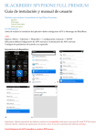
A simplified schematic of the hardware of a typical tracking device is illustrated in figure
1. The Global Navigation Satellite System (GNSS) block shown in the figure is a combination of GPS and a GLONASS receiver. It is used for acquiring a very accurate location of the device by using GPS and GLONASS satellites together. In order to work
properly, the GNSS requires a clear view to the sky.
The Global System for Mobile Communications (GSM) network is used to provide remote access to the device. It is also used for positioning, as it will expose identification
of the base station, which can be converted to actual coordinates by using the OpenCellID database [4.]. However, this gives only a hint of the actual location since a GSM
cell tower covers an area from a few meters up to tens of kilometers [5.]. Nevertheless,
a hint of the location is better than no location at all.
The accelerometer is providing information on how the device is moving. The information is used to determine how often the device should acquire a new location with
the following principle: if the device is not moving, its location has not changed and
acquiring a new location would be useless. Thus, the accelerometer is used to save
power.
Last but not least is the application processor which is binding the whole system together. The application processor contains all the software logic that controls and interacts with the other components forming a tracking device system.
4
Figure 1. A simplified flow-chart of the contents of a tracking device.
5
3
Bluetooth in General
Bluetooth is a short-range wireless communication technology, and like many other
wireless communication technologies, it employs radio waves to transmit and receive
information in universal 2.4 GHz ISM-band. In fact, it is just a set of requirements in
form of a specification, which the product needs to satisfy, in order to achieve interoperability with other Bluetooth devices. [3.]
The Bluetooth SIG is the organization behind the Bluetooth specification. The organization consists of over 20,000 companies including all the leading technology companies.
Its responsibility is to develop the Bluetooth standard and supervise products that are
using it. A company that is using Bluetooth technology in a product must become a
member of the SIG in order to use Bluetooth SIG’s intellectual property and the Bluetooth brand. [6.]
Bluetooth was originally invented to replace serial cables with wireless links. However,
like most great inventions, Bluetooth expanded. Nowadays Bluetooth can be found
almost in every consumer device, serving a wide range of different use cases. For example, it is used in products like smart-phones, toothbrushes [7] or even in valve caps
of the car tire [8], not to mention today’s trend, the wearables, in which Bluetooth has
become a standard. In addition, it is playing a significant role in today’s automotive industry by providing solutions for hands-free communication and in-car entertainment.
Also, it has been considered as a break-through in concepts like smart home and the
internet of things. [9.]
The Bluetooth specification version 1.0 was released in the year 1999, with the Basic
Rate standard, which is often known as the classic Bluetooth. After that, the specification has been frequently updated especially to satisfy ever-increasing amount of data.
Along with the specification version 4.0 in the year 2010, a totally new standard was
introduced to the world, known as Bluetooth low energy (LE). Bluetooth LE is representing a completely new way of thinking since it is the first time that Bluetooth has
dramatically decreased the data speeds and protocol complexity to achieve the lowest
possible power requirements, this way adding opportunities for new kind of use cases
and innovations. [10,26.]
6
4
Low Energy Technology
Bluetooth LE is a new technology, an alternative to classic Bluetooth, not a replacement. It is created to support completely different use cases and market segments than
its parent. [10,37.]
LE is intended to be used in devices which have to operate with a limited amount of
energy (e.g. coin-cell battery) for very long periods of time. These devices can be any
kinds of detectors, indicators, or sensors. It is not useful in products like wireless headphones which involve long connection periods in which large amount of data is exchanged. [10,26.]
It has been claimed to consume only a fraction of power compared to classic Bluetooth.
These power savings are the outcome of great sacrifices in performance, which causes
limitations for the technology. For example, LE technology is not capable of audio
streaming. [10,29.]
Although LE technology carries the Bluetooth brand, it is not directly compatible with
the classic Bluetooth. However, it has borrowed a lot of technology from its parent. This
allows it to be implemented in the same silicon with the classic Bluetooth with almost
zero additional costs. [10,75.]
Bluetooth Smart and Smart Ready are new marketing names for Bluetooth enabled
products. Smart is the name of the product that is carrying LE technology inside and
Smart Ready is the name for a hybrid product that supports classic and LE technologies. [11,15.]
Typical smart products are peripheral devices which have a very limited energy capacity like car keys, TV-remote controllers, or any type of sensor units. Smart Ready products are central devices such as smart-phones, tablets, or TVs.
4.1
Limitations
The technology with the lowest possible power consumption has its limitations. First of
all, the speed of data over the air from application to application, i.e. application
7
throughput, has the absolute theoretical maximum of 250 kilobits per second with bulktransmission. However, when taking into account possible signal fading, interference,
and packet overhead, a more realistic estimate for application throughput is about 5
kilobits per second. Still, maintaining this kind of speed for longer periods of time would
draw a relatively large amount of power and thus kill the concept of low power. [11,19.]
Second of all, the coverage area (i.e. range) is typically not more than 10 meters. It is
not restricted directly by the specification but by the power consumption. The more
power is used to transmit the signal, the further it will radiate. It is left for the user to
decide the best range – power consumption ratio. [11,21.]
4.2
Radio
LE operates in 2.4 GHz unlicensed ISM radio band. The spectrum range is from 2402
to 2480 MHz, which is divided into 40 individual 2 MHz wide RF-channels. Technology
uses a technique called frequency hopping to combat against interference at the wildly
used spectrum. Three of the 40 channels are used only for broadcasting advertisements and these are located in the spectrum as far from the known channels used by
the Wi-Fi access point as possible to allow robust device discovery. [10,97.]
4.3
Functionality
From the application developer point of view the LE technology will provide capabilities
to advertise, scan, and connect. These capabilities can be used to discover other devices and to be discoverable to other devices as well as connect to other devices and
be connectable to other devices. [11,34.]
A device could use advertising to inform about its presence to nearby devices and even
include small amounts of dynamic data to the advertisement, e.g. services that the device supports. A device that uses scanning functionality listens to these advertisements. After receiving one advertisement, it may attempt to request more information of
the advertiser (i.e. a scan request) or initiate connection with it (i.e. a connection request). When the connection is established, the advertising device becomes a slave of
the connection and the initiating device becomes the master. A master could connect
8
with multiple slave devices at the same time, but a slave can be connected with only
one master. Basically this means that the master can be connected with one or more
slave devices and at the same time scan for other devices. A slave could also advertise
while connected to the master, but that advertising shall not lead to connection. [11,40.]
4.4
Security
Technology has taken security considerations into account by supporting encrypted
connections and private device addresses to combat against eavesdropping and man
in the middle attacks. [11,50.]
A procedure called pairing may be used to create temporary encryption with any ongoing connection with the approval of both devices. A more permanent encryption procedure is called bonding, where both devices agree to share and save an encryption
key (i.e. a shared secret) to be used to encrypt the link in future connections. [11,51.]
A private device address is a random address that changes periodically, but is resolvable for the bonded device. This can be used to hide the identification of the device from
third parties. [11,50.]
4.5
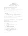
Protocol Stack
The protocol stack shown in figure 2 describes the software implementation of the protocols according to which Bluetooth LE operates. As can be seen in the figure, it follows the same layered architecture as classic Bluetooth. The figure also shows how the
protocol stack is split up in two entities: controller and host. [11,31] This division is
made on the basis that both entities have very different timing requirements from the
system they are running on. As a result, this allows them to be implemented separately. [12.]
The controller includes the hardware for the radio and the software that controls it. It is
typically implemented separately in the form of a small chip, because the radio control
has strict requirements for the timings. [12.]
9
The host entity is a pure software stack that is responsible for higher level functioning
providing an application programming interface (API) to the application and profiles. It
has many more relaxed timing restrictions compared to the controller. That is why it is
often implemented directly to the application processor along with the user’s application.
These two entities are connected through Host Controller Interface (HCI), which is delivered either logically (API) or physically (UART) depending on the implementation
[11,44]. The host is controlling the controller with HCI commands defined in the Bluetooth specification [13,603].
Generally speaking, the controller is often referred to as the Bluetooth hardware and
the host is referred to as the Bluetooth stack.
Figure 2. The protocol stack of the Bluetooth low energy. Modified from [11,32].
Implementation Options
The host part of the protocol stack is supported natively in generic operating systems
such as Windows, Android, and OSX. This is because devices that are running on
10
these operating systems usually have enough processing power and memory for that.
The controller part is then implemented by the hardware if needed.
Devices like embedded systems, which usually rely on low power microcontrollers, are
not capable of native support of the protocol stack. The only choices are to develop or
purchase platform independent protocol stacks or to use a module that implements the
whole protocol stack in single individual housing (system-on-chip).
4.6
Bluetooth Device Address
Every Bluetooth device has a unique device address that identifies that particular device from the others. The device address is a 48-bit MAC-address that is divided into
two. The first half of the address is company specific and the other half is device specific. There are also two types of addresses that the device may use. [11,36.]
Public Device Address
A public device address is a fixed address that is assigned to a particular device. It
must be registered with the IEEE Registration Authority and must never be changed
during the lifetime of the device. [11,37.]
Random Device Address
A random device address is showing to other devices just like the public address, but it
is periodically changed and randomly generated. It hides the identity of the device from
strangers but may be resolvable if desired (i.e. private address). [11,37.]
4.7
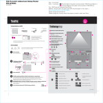
Device Discovery
Advertising and scanning procedures are the foundation of every application that is
designed around Bluetooth LE. These procedures used together enable device discovery. Without device discovery, LE devices cannot be aware of each other. Without
awareness, the devices could not connect with each other and without connection they
could not exchange data. A device using advertising is called an advertiser and a device that is using scanning is called a scanner. How these procedures work in simple
11
terms is illustrated in figure 3. The advertiser broadcasts itself to the nearby terrain and
the scanner listens out for these advertisements. In order to utilize these procedures in
an application, a more thorough explanation is well justified. [11,38.]
Figure 3. Scanner listening advertisements. [10,125]
Before getting to more detail, a few basic concepts must be explained. First of all, LE
employs only one packet format (see figure 4) for all data that is exchanged through
air. The PDU field showing in the figure holds the actual payload inside. LE defines two
types of PDUs: advertising and data. As can be concluded from the figure, the maximum packet is 376-bit long and the minimum packet is only 80-bit. The LE radio works
with a 1 Mbps bit rate, which means that the longest possible packet would take 376
micro seconds and the shortest 80 micro seconds to transmit over the air. [10,130.]
Figure 4. Over-air data packet format. Modified from [10,140].
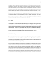
Second of all is the concept of channels. As mentioned before, LE technology divides
the over the air traffic into 40 RF-channels. Figure 5 shows how the channels are indexed and spread over a 2.4 GHz ISM-band. The channels are divided into two
groups: advertising and data. Channels 37, 38, and 39 are advertising channels and
only used for device discovery purposes. They are located on the band as far away
from each other as possible to enable robust device discovery even in bad conditions
with the principle that at least one channel is accessible anytime. Another factor which
has affected the location of the advertising channels is the Wi-Fi access point, which
uses the same ISM-band. [10,143.]
12
Figure 5. ISM-band divided into 40 RF-channels [12].
The basic idea behind device discovery is that one device has to listen in the same
channel at the same time when another one is sending a packet. This packet includes
information that identifies the device. In other words, one device has to be an advertiser and the other one has to be a scanner. At this point, the devices are not in synchronization with each other, which means that either advertising has to be frequent or
scanning continuous in order for the scanner to receive the packet.
Advertising
Advertising is a continuous loop which consists of short advertising events that are repeated periodically. An advertising event is a process during which the device transmits
an advertising packet in every advertising channel. The interval between advertising
events is user adjustable, and it could be ranging from 20 milliseconds to 4 seconds.
[10,122.]
Scanning
Scanning is also a continuous loop the behavior of which is controlled with interval and
window parameters. The scan interval is a value from 2.5 milliseconds to 10.24 seconds, which determines how long one advertising channel is active after the channel is
switched. The scan window is a value with the same range as the scan interval; it determines how long one advertising channel is actually listened to. The window shall not
13
be longer than the interval because the radio can be tuned to only one channel at the
time. [10,124.]
Practical Example
In device discovery, the developer could easily misunderstand the operation principle
of device discovery without having the knowledge of how it works. This section shows a
practical example of a device discovery scenario.
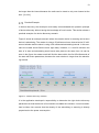
Figure 6 shows an example scenario where the master device is scanning and a slave
device is advertising. The master is using a 50 millisecond scan interval and a 25 millisecond window and the slave is using a 20 millisecond advertising interval. In this scenario the master would find the slave right away. However, in a real life situation the
start of a scan and advertising would never take place at the same time. As can be
seen in the figure, the master would still find the slave within the first 25 milliseconds of
the start with these parameters, because the scan window is longer than the advertising interval.
Figure 6. A device discovery scenario.
It is the application developer’s responsibility to determine the right device discovery
parameters so that the device is found within a suitable time window. It must nevertheless be taken into account that the density of the advertising or scanning is directly
proportional to the power consumption.
14
4.8
Connections
After the devices have discovered each other, they may decide to form a more permanent relationship, a connection. A connection is initiated when the initiator device sends
a connection request as a response to the advertising packet. An initiator is a device
which acts just like a scanner but is only interested in the specific advertiser. When the
connection is initiated, the initiator becomes the master and an advertiser becomes a
slave of the connection. [10,125.]
15
5
Lapis Semiconductor ML7105
The ML7105 is a Bluetooth LE compliant system-on-chip integrated circuit (later
ML7105 chip). The manufacturer, Lapis Semiconductor, is a Japanese semiconductor
manufacturer specialized in low-power consumption integrated circuits. The ML7105
chip was used in this final year project and the exact model used was a second generation ML7105-002 chip. [15,1.]
The company behind the Bluetooth LE solution inside the ML7105 chip is called MindTree. It develops platform independent Bluetooth solutions. The solution used in
ML7105 is their product named BlueLitE. [16.]
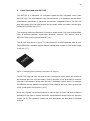
The ML7105 chip shown in figure 7 is manufactured in a WQFN package with 32 pins.
The WQFN32 is a standard square shaped package with a width of 5 mm and a height
of 0.8 mm. [17.]
Figure 7. Enlarged picture of the ML7105 system-on-chip [13].
The ML7105 chip has very low peak-current consumption which allows the product to
be powered with one coin-cell battery. During operation it has promised to consume
less than 3 microwatts in sleep state and only 3 milliwatts in active state. For example,
the CR2032 coin-cell battery has capacity of 230 milliamps per hour, which gives a hint
of the overall power consumption. [15,1.]
Since the LE stack can be implemented in various ways, the ML7105 chip provides a
possibility for the user to choose from three implementation setups known as operation
modes. [15,5.] The operation modes and their differences are described in following
sections.
16
5.1
Operation Modes
The operation modes that the ML7105 offers are called BACI-, HCI-, and RAM-mode.
Depending on the use case and the product type, each mode has its advantages and
disadvantages. [15,5.]
The operation mode is selected with physical (i.e. hardware) configuration. At the power-up, the ML7105 will start in the selected mode and ML7105 is after that used in accordance with the mode. [15,5.]
Each operation mode has a different host interface, in physical and logical manner. The
interface defines how the chip is physically (i.e. hardware) coupled and how it is logically (i.e. software) controlled. The same LE features are available in each operation
mode, but the way they are used differs. [15,9.]
The following sections describe each operation mode, their interface and ideal use
case.
17
BACI Mode
The Bluetooth Application Controller Interface (BACI) mode is the default mode. As
shown in figure 8, it includes implementation of the LE host and the controller stack
which are used through a vendor specific interface, called the BACI interface. [15,5.]
Figure 8. Protocol stack of the BACI-mode. Modified from [15,5].
This means that the ML7105 chip internally handles most of the work that is needed to
accomplish the correct operation and provides a higher layer interface to the user. Basically, it shuts the user out from the complex logic and allows him or her to concentrate on the application. This mode is ideal in products that are using a low-power microcontroller, like most embedded systems.
The clear advantage is that the user does not necessarily need to know much of the
technology, just the essentials. Also from the developer point-of-view, the software will
be easier to develop because of the higher layer interface.
The disadvantage is that the BACI interface ties the whole system to this particular
system-on-chip. Switching the vendor would mean switching the interface and the
software logic that it is built around it.
18
HCI Mode
An alternative choice is the Host Controller Interface (HCI) mode. As shown in figure 9,
it includes implementation only of the LE controller stack. That is why in this mode, the
ML7105 chip can be used through a standardized HCI interface. [15,6.]
Figure 9. Protocol stack of the HCI-mode. Modified from [15,6].
This means that the ML7105 chip can be controlled as any Bluetooth LE compliant chip
on the market. This also means that the microcontroller must implement the LE host
stack, which is a complex piece of software that requires memory, processing power
and deep technical expertise to develop. That is why this mode is ideal in products that
already have a powerful processor and generic operating system that has native support for the LE host stack, like laptops and smartphones.
The advantage in this mode is that the system is not tied to this particular system-onchip and it can be changed anytime because of the standard interface.
The disadvantage is the amount of work that is needed to implement this to the platform that does not have native Bluetooth LE host stack support. Also this requires
knowledge of the technology.
19
RAM Mode
In RAM-mode the ML7105 chip works as a host for user applications, which means no
external microcontroller is needed as shown in figure 10. [15,6.]
Figure 10.
Protocol stack of the RAM-mode. Modified from [15,6].
The application developer creates the application code by using APIs provided by the
BlueLitE stack. The code is loaded directly to an EEPROM memory chip, from where
the ML7105 chip is loading it during the start-up procedure. This operation mode does
not require an external microcontroller. The ideal product which would benefit of RAMmode would be something very simple, like a temperature sensor unit.
The advantage in this mode is the saving in product material costs, and that with fewer
components the PCB size can be minimized. This allows the user to build smallest, the
most power constrained and the cheapest Bluetooth LE products.
The disadvantage in this mode is that the application code is not necessarily compatible with other systems and it ties the user to this particular system-on-chip. Also, the
application has very restricted size and interfacing resources, which usually becomes a
serious problem when new features are added and the applications size expands.
20
6
Implementation of the ML7105
This final year project was a part of the Navigil’s research project for which the ML7105
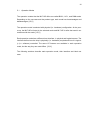
chip was chosen and implemented on a tracking device, as illustrated in figure 11. This
final year project was about implementing a software module in the application processor to interface with the chip and provide an API for the application to use the features
that the chip offers.
Figure 11.
A block diagram of a tracking device with Bluetooth LE capability.
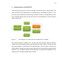
As mentioned earlier in chapter 2.4.1, the ML7105 chip has three different operation
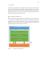
modes from which the BACI-mode was selected to be used. Figure 12 shows the software block diagram of the Bluetooth LE implementation. From the figure it can be seen
that the BACI controller provides access to Bluetooth LE functionality through the BACI
interface. Thus, the BACI interface allows Bluetooth LE profiles and application to be
implemented in a separate application processor.
21
Figure 12.
Software block diagram of the Bluetooth LE implementation. Modified from [15,5].
In order to utilize the features that the BACI controller provides, there must be a BACI
host. The BACI host, showing in figure 12, must be implemented in the application processor. It is software implementation that interfaces with the BACI controller through a
physical interface, called BACI interface, and provides an interface to the application
and possible LE profiles.
Later sections explain how the BACI host was designed and how it works. Before that
the BACI interface is introduced in more detail.
6.1
BACI Interface
The BACI interface shown in figure 13 is composed of multiple signals which the host
uses to control and communicate with the controller. From the figure it can be seen that
the power control is handled with a reset signal, and communication is based on SPI
transport and that communication flow is controlled with flow-control signals.
22
Figure 13.
The BACI Interface. Modified from [5,9].
The communication is half-duplex, meaning that only the host or the controller can
speak at a time. A turn for sending data is requested with a flow-control signal and the
actual data is delivered over an SPI transport layer. The conversation is based on the
BACI protocol, which defines predetermined messages that both parties should understand.
BACI Protocol
The BACI protocol is a Lapis Semiconductor’s proprietary protocol which allows access
to BlueLitE APIs through a physical BACI interface. It is a message based protocol
which defines commands, events, and data packets. As illustrated in figure 14, commands are requests from the host and events are responses from the controller. The
BACI data packets encapsulates ATT [13,1829], SMP [13,1980], and L2CAP [13,1383]
protocols defined by the Bluetooth specification.
23
Figure 14.
The BACI message protocol. Modified from [18,9].
All these packets are packaged in a single BACI packet format showed in figure 15.
The header is a three octet long informative field, which contains all information needed
to decode the payload of the packet. It includes the type of the packet, and an identifier
of a particular command, event, or data packet and the length of the following payload.
Figure 15.
The frame of BACI protocol packet. Modified from [18,10].
24
BACI Commands
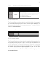
The BACI protocol defines 38 different commands. The BACI commands are requests
for the controller to perform a specific procedure. There are also defined commands to
read or write values to registers related, for example, radio characteristics. Every command may have a set of parameters which are used to adjust the meaning of the command. The following will introduce a few useful commands to provide better understanding of how they are used. [18,4.]
6.1.2.1 Configure
The Configure command is used to start an advertising or a scanning procedure at the
LE controller. As shown in table 1, the command includes a role parameter that determines which procedure is started. If the role is set to advertising, the advertising related
parameters are filled with desired values, and vice versa. The advertising and scanning
related parameters are well documented in the Bluetooth specification [13].
Table 1.
Description of the Configure command. Modified from [18,12].
Value
Description
BACI Command
Configure command
Length of the payload is 23 octets.
Configure as a scanner(0x00) or advertiser(0x01).
Packet type:
Command Id:
Length:
Role:
0x01
0x0F
0x17
0x00-0x01
Advertising
Parameters:
15 octets
Advertising related parameters as defined by the LE Set Advertising
Parameters command in the Bluetooth Specification [13,1058].
Scanning
Parameters:
7 octets
Scan related parameters as defined by the LE Set Scan Parameters
Command command in the Bluetooth Specification [13,1066].
6.1.2.2 Connect
The Connect command is used to start a connection procedure at the LE controller. As
shown in table 2, the command includes connection related parameters that are well
documented in the Bluetooth specification [13].
25
Table 2.
Description of the Connect command. Modified from [18,13].
Value
Packet type:
Command Id:
Length:
0x01
0x08
0x19
Connection
Parameters:
25 octets
Description
BACI Command
Connect command
Length of the payload is 25 octets.
Connection related parameters as defined by the LE Create Connection
command in the Bluetooth Specification [13,1058].
BACI Events
The BACI protocol defines ten different events. The BACI events are responses to
some specific command or indication of some specific event occurring on the BACI
controller. Every event may have a set of parameters giving more information of the
event. The following will introduce a few example events.
6.1.3.1 Start Up
The Start Up event is received after the BACI controller is waken up from sleep or as a
result of the reset. As shown in table 3, the event has only one parameter that indicates
the state of the BACI controller. If the status is not that of a normal startup, the default
configuration has not yet loaded or it is incorrect. After receiving this event with a normal startup status, the BACI controller is ready for action.
26
Table 3.
Description of the Start Up event. Modified from [18,14].
Value
Packet type:
Command Id:
Length:
Description
BACI Event
Start Up event
Length of the payload is 1 octet.
0x04
0x01
0x01
Startup State:
Startup state indicates the status of the BACI controller.
0x00 ==> Normal startup
0x01 ==> Request for Get Config Parameters, EEPROM not connected
0x02 ==> Requset for Get Config Parametes, EEPROM connected
0x03 ==> RAM_IMAGE_SIZE_BIG
0x04 ==> RAM_IMAGE_CHECKSUM_FAILED
0x00-0x04
6.1.3.2 Command Status
The Command Status event informs about the result of the initiation of processing of
the corresponding command. As shown in table 4, the event has two parameters. The
first parameter is the identifier of the corresponding command. The status of which is
informed in the second parameter.
Table 4.
Description of the Command Status event. Modified from [18,15].
Value
Packet Type:
Command Id:
Length:
Command Code:
Status:
0x04
0x02
0x02
0xXX
0x00 - 0xFF
Description
BACI Event
Command Status event
Length of the payload is 2 octets
Identifier of the command
Result. 0x00 represents success.
6.1.3.3 Command Complete
The Command Complete event informs about the completion of the processing of the
corresponding command. As shown in table 5, the event has a few parameters and
variable length payload. The Command Code parameter indicates the corresponding
command the status of which is informed in the Status parameter. If the processing of
the command has not succeed, the status represents an error code. The error codes
are documented in the Bluetooth specification [13]. Because each command can return
a different result, the contents of the Command Parameter field are depending on the
corresponding command.
27
Table 5.
Description of the Command Complete event. Modified from [18,16].
Value
Packet Type:
Command Id:
Length:
Command Code:
0x04
0x03
0x03 - 0x23
0xXX
Status:
0x00 - 0xFF
Command
Parameter
Length:
Command
Parameter(s):
Description
BACI Event
Command Complete event
Length of the payload is at least 3 octets.
Identifier of the command
Result, where 0x00 represents success. Any other value represents
"Error Codes" defined in Bluetooth specification [13,585].
0x00 - 0x20
Length of the parameters depends on the corresponding command.
0 - 32 octets
Return parameters depend on the corresponding command.
BACI Data
The BACI protocol defines three types of data packets for ATT [13,1829], SMP
[13,1980], and L2CAP [13,1383] protocols. Table 6 presents the template of the BACI
data packet.
Table 6.
Template of the BACI data packet.
Value
Packet type:
Command Id:
Length:
0x02
0x01 - 0x06
0xXX
Description
BACI Data
BACI Data packet type
0x01 ==> ATT event
0x02 ==> ATT command
0x03 ==> SMP event
0x04 ==> SMP command
0x05 ==> L2CAP event
0x06 ==> L2CAP command
Length of the payload BACI Data payload.
28
6.2
BACI Host
The BACI host is implemented as a software module that controls and manages the
behavior of the BACI controller to accomplish requested LE procedures, such as scanning, advertising and connections. The software module is designed in accordance with
guidelines and practices used in Navigil. The following chapters introduce the BACI
host software module and describe how it works.
Architecture of the BACI Host
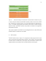
Figure 16 illustrates the software architecture of the BACI host. It shows how the module is built-up from individual components, which are functioning as a whole. Each
component has a clear interface and function. In the source code, the components are
separated in their own folders and each may include multiple files. This eases the
maintainability and further development of the module.
Figure 16.
The architecture of the BACI host.
29
Design Guidelines
Navigil requires that any module that is implemented in their environment follows certain design-model and architectural appearance.
A module should define a set of interface functions (i.e. API) visible to the user (i.e.
public), including at least initialization and timer functions. Also, the module may have a
set of functions usable only from within the module (i.e. private) and functions that are
introduced and used by the module but should be implemented by the user (i.e.
callback).
All data that a module uses must be in a single data structure owned by the user (i.e.
master). The data structure should contain at least one sub-data structure, an implementation of initial data, which may include some configuration parameters for the
module (e.g. GPIO lines), and possibly a pointer to the master data structure when
callback functions are used.
The initialization is the first function that the user must call. It should have two parameters, a pointer to the module’s own data structure and a pointer to the initial data structure. The initial data should be set by the user with the desired configuration. Function
implementation should at least clear its own data structure, and after that, copy the
initial data contents there.
The timer function is called by the user in certain fixed intervals, e.g. 100 milliseconds,
after the module is initialized. The purpose of this function is to provide a sense of time
to the module. The module may utilize this function to count time and trigger timerelated activities.
30
Application Programming Interface
The Application Programming Interface (API) introduces all possible services that the
module offers to the application. Each API function has at least one parameter, which
is a pointer to its own data structure.
6.2.3.1 Initialization
The initialization function shown in listing 1 is the first function that must be called by
the system in order to ensure correct operation. Its job is to set all variables in the
known initial state.
void ML7105_vInit(tsML7105Data
*psInitData);
*psData,
tsML7105InitData
Listing 1. The prototype of the initialization API function.
Implementation of the initialization function clears out the data structure of its own and
copies the initial data structure in its own data structure. After that, it ensures that the
ML7105 chip is in shutdown mode by configuring the reset signal to low. Finally it initializes the interface driver and calls for a state change to the Power Down state from
the control and management component.
6.2.3.2 Timer
The timer function shown in listing 2 must be called periodically with 100 millisecond
intervals, but only after the module is initialized. Its job is to give the module a sense of
time to allow triggering time based activities, for example to count down timeouts between activities.
void ML7105_vTimer(tsML7105Data *psData);
Listing 2. The prototype of the timer API function.
31
6.2.3.3 Configure
The configure function shown in listing 3 is used to invoke the start-up or shutdown
procedure for the chip. It has two parameters, which are power state and Bluetooth
device mac-address. The power state parameter determines whether the user wants to
shut down or start up the module. When starting up for the first time the Bluetooth device mac-address must be supplied. In case of restart the mac-address is optional, and
if not supplied, the same address is used as before.
void
ML7105_vConfigure(tsML7105Data
*psData,
bPowerOn, tsBleMacAddress *psLocalAddress);
BOOL8
Listing 3. The prototype of the configure API function.
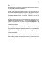
The implementation of this function simply commands the control and management
component to activate the appropriate state, as shown in figure 17. In case of start-up
or restart, mac-address is passed to the component as an argument.
Figure 17.
The flow-chart presentation of the configuration API.
32
6.2.3.4 Control
The control function demonstrated in listing 4 is used to invoke advertising, scanning,
connecting, or disconnecting procedures on the chip.
teBleRequestStatus
ML7105_eControl(tsML7105Data
tsBleControlRequest *psRequest);
*psData,
Listing 4. The prototype of the control API function.
The implementation of the control function conveys the request to the control and management state machine, which returns the request status. In other words, the state that
is currently active decides the fate of the request. It has one parameter, which is a
pointer to control request data structure. Listing 5 shows the implementation of the data
structure. It is composed of an identifier and data of the corresponding request.
typedef struct{
teBleControlRequestType
tuBleControlRequestData
eRequest;
uData;
} tsBleControlRequest;
Listing 5. The implementation of control request data structure.
Listing 6 shows the implementation of the control request identifier, which is an enumeration of all possible control requests.
typedef enum
{
BLEREQ_ADVERTISE,
BLEREQ_SCAN,
BLEREQ_CONNECT,
BLEREQ_DISCONNECT,
} teBleControlRequestType;
Listing 6. The implementation of the control request identifier.
33
The function has a return value, which indicates the status of the request. Listing 7
shows the implementation of the request status and all possible return values.
typedef enum
{
REQ_STATUS_OK = 0,
REQ_STATUS_REQUEST_NOT_DEFINED = 1,
REQ_STATUS_IGNORED = 2,
} teBleRequestStatus;
Listing 7. The implementation of the request status enumeration.
6.2.3.5 Callback Functionality
This software module uses one callback function to inform the user with indications of
certain events during operation. The indication function is introduced by the module but
must be implemented by the user. The prototype of the function is shown in listing 8.
void _ML7105CALLBACK_vSendIndication(void
teBleIndType eType, tuBleIndData *puData);
*pvCallbackData,
Listing 8. The prototype of the send indication callback function.
The function has three parameters. The first parameter is a void pointer to the user
master data. The second parameter is the identifier of the corresponding indication, as
listing 9 shows; the identifier is an enumeration of all possible indications. The third
parameter is the data of the corresponding indication.
typedef enum
{
BLEIND_READY,
BLEIND_CONNECTED,
BLEIND_DISCONNECTED,
BLEIND_SCAN_REPORT,
BLEIND_SCAN_END,
BLEIND_ADV_END,
BLEIND_CONNECT_END,
} teBleIndType;
Listing 9. The enumeration of the types of indications.
34
Control and Management
The control and management is a state machine, which is composed of states that are
responsible for scanning, advertising, connecting, and managing the connection. Only
one state can be active at once, which is called the current state. The current state has
access to BACI protocol commands to invoke procedures in the chip. It also supervises
the operation of the chip by listening to BACI protocol events from the chip. States can
also send indications of the course of events to the user by callback functionality.
The state may be composed of multiple sub-states, which each have one specific task.
Typically the sub-state’s task is to send one command to the chip and wait for the response and move to the next sub-state.
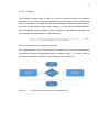
Figure 18 shows all possible state transitions. Transition from one state to another can
be triggered by the current state itself or by the user with configure or control requests.
Figure 18.
The control and management state machine.
35
6.2.4.1 Power Down State
As a result of initialization, the state machine transits to Power Down state. The Power
Down state can be triggered anytime by the user with a configure request. The purpose
of the state is to run shutdown procedure for the chip. This is done simply by setting the
reset signal to low state. The state is valid until the module receives a configure request from the user.
6.2.4.2 Init State
As a result of the configure request, the state machine transits to the Init state. The
state can also be triggered by any other state in case of error. An error could occur, for
example, if the chip does not respond to a command within certain time. The purpose
of the state is to reset and execute the start-up procedure to the chip. The start-up procedure is a multi-step process in which the configuration file is loaded to the chip including the Bluetooth address for the device. When initialization is completed, the state
machine will transit to the idle state. The message sequence chart in figure 19 shows a
successful start-up procedure.
36
Figure 19.
A message sequence chart of the initialization procedure.
37
6.2.4.3 Idle State
After a successful execution of the Init state, the state machine enters the Idle state.
The Idle state is a standby state, which does not do anything, but it indicates that the
module is ready for a control request. This state will accept control requests for scanning, advertising, and connection procedures. After successful execution of a certain
procedure, the state machine will enter back to the Idle state.
6.2.4.4 Scan State
As a result of the control scan request, the state machine transits to the Scan state.
The purpose of the state is to enable the LE scanning procedure in the chip, which is
described in the Bluetooth specification [13,2229]. Parameters related to the scanning
are supplied by the application, in the control request data of the scan request. The
contents of the data are shown in listing 10.
typedef struct
{
UINT16
UINT16
UINT16
teBleScanType
teBleScanFilterPolicy
u16ScanDuration_100ms;
u16ScanWindow_10ms;
u16ScanInterval_10ms;
eType;
ePolicy;
} tsBleControlRequest_Scan;
Listing 10. The structure of the scan request data.
The scan duration parameter is a timeout value for the state to turn-off the scan procedure when the timeout is expired. If desired, the user can choose to request for a permanent scan with duration value of zero.
During the scan procedure the chip will send an advertising event of each found peer
device. The state reports these events to the application with scan reports via a
callback function. The scan report includes information about the address and the signal strength of the peer device, as well as information about the advertising event type
and possible advertising data, as shown in listing 11.
38
typedef struct
{
tsBleMacAddr
INT8
teBleAdvType
tsBleAdvData
sPeerAddress;
i8RssiLevel;
eAdvertisingType;
sAdvertisingData;
} tsBleInd_ScanReport;
Listing 11. The structure of the scan report data.
The message sequence chart in figure 20 shows a successful scanning procedure,
where two peer devices were found.
Figure 20.
A message sequence chart of the scan state.
6.2.4.5 Advertise State
As a result of the control advertising request, the state machine transits to advertising
state. The purpose of the state is to enable the LE advertise procedure in the chip,
which is described in the Bluetooth specification [13,2222]. Parameters related to the
advertising are supplied by the application in the data of the advertising request. The
contents of the data are shown in listing 12.
39
typedef struct
{
UINT16
UINT16
teBleAdvType
tsBleMacAddr
teBleAdvChanMap
teBleAdvFilterPolicy
u16AdvDuration_100ms;
u16AdvIntval_10ms;
eType;
sDirectAddress;
eChannelMap;
ePolicy;
} tsBleControlRequest_Advertise;
Listing 12. The structure of the advertise request data.
The advertising duration is a timeout value for the state to turn off the advertising procedure when the timeout is expired. If desired, the application can choose to request
for permanent advertising with duration value of zero.
If the advertising parameters allow, any peer device may attempt to request a connection during advertising. In case of the connection request, the state will transit to the
Connected state and connection indication with the address of the peer will be sent to
the user via a callback function.
The message sequence chart in figure 21 shows the advertising procedure where a
remote device establishes a connection to it.
Figure 21.
A message sequence chart of the advertise state.
40
6.2.4.6 Connect State
As a result of the control connect request, the state machine transits to the Connect
state. The purpose of the state is to enable the LE initiating procedure in the chip,
which is described in the Bluetooth specification [13,2231]. Parameters related to the
connection are supplied by the application in the data of the connect request. The contents of the data are shown in listing 13.
typedef struct
{
UINT16
UINT16
UINT16
teBleInitiatorFiltPol
tsBleMacAddr
UINT16
UINT16
UINT16
u16ScanDuration_100ms;
u16ScanWindow_10ms;
u16ScanInterval_10ms;
eFilterPolicy;
sPeerAddress;
u16ConnectionIntval_10ms;
u16ConnectionLatency;
u16SupervisTimeout_100ms;
} tsBleControlCmd_Connect;
Listing 13. The structure of the connect request data.
The initiating procedure will be active until connection is established or until the scan
duration timeout value is expired. If the scan duration is set to zero, the connection
procedure is running until the connection is established. When the connection is established the state will transit to the Connected state. If the timeout is reached, the state
will transit to the Idle state and the user will receive connect ended indication.
The message sequence chart in figure 22 shows a successful execution of the connect
request.
41
Figure 22.
A message sequence chart of connect state.
6.2.4.7 Connected State
As a result of the connection establishment at the chip, the state machine transits to
the Connected state. The purpose of the state is to monitor the LE connection procedure in the chip, which is described in the Bluetooth specification [13,2231]. The connection may occur as a result of advertising or a successful control connection request.
This state’s job is to monitor the state of the connection. If the chip informs that the
connection is disconnected by the remote device or some other issue, the state will
transit to the Idle state and send disconnection indication to the user.
The message sequence chart in figure 23 shows the situation when the user requests
for disconnection.
42
Figure 23.
A message sequence chart of successful disconnection.
Interface Driver
The interface driver is the lowest layer of the software module. It includes implementation of each possible BACI command and data message that the upper layers can send
to the controller. More importantly it implements the communication logic needed to
send and receive data between the host and controller.
6.2.5.1 Communication Logic
The communication logic masters the data transfer and flow-control logic with the controller. Its job is to report in-coming event messages to upper layers, while providing
them an ability to send data back to the controller.
Interrupts are used to obtain a short respond time to flow-control. Although the chip
does not require fast interaction, it is mandatory when fast throughput is needed, for
example, it would be needed during the scanning procedure when several devices
have been found in a short period of time.
Even though the transmission is happening in an SPI transport layer, the communication principle is half-duplex. It means that only the host or the controller can send data
at a time. If one party has data to send, it must request an opportunity for transmission,
and the other party must indicate that it is ready to receive. The flow-control signals are
used for this purpose. The host uses the WAKEUP signal to indicate the request or
ready state, and the controller uses the IRQ signal.
43
Because of the flow-control logic, it was natural to use state machine approach in the
implementation of the communication logic. The communication state machine is composed of Idle, Request, and Ready states, as shown in figure 24.
Figure 24.
The communication state machine.
From the host point-of-view, the request state is entered when a request from the controller is detected. The ready state is entered when the controller accepts a request
from the host. Both of these situations are illustrated in figure 25.
Figure 25.
Data transfer initiated by the host and the controller.
44
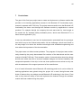
7
Conclusions
The goal of this final year project was to create and implement a software module that
provides to the tracking applications access to the Bluetooth LE functionality implemented in separate a ML7105 chip. The project was successful since the Bluetooth LE
functionality has been used through this software module by applications in actual
products. For example, Navigil, the company the work was made for, has brought to
the market the S1 wearable safety wristwatch phone, which uses Bluetooth LE in a
home beacon application [19.].
It was very educational to see how the implementation proceeded from the prototype
level all the way to the finished end product. All the challenges, which were faced on
the way taught a lot about the wireless technologies and embedded engineering and
even about the importance of the documentation.
The project was not without actual problems. The progress of the project was continuously slowed by the poorly documented first versions of the data sheet and the user
manual of the ML7105 chip. That caused a series of misconclusions about how things
should work which then led to incorrect hardware designs and caused instability and
unexpected operation of the chip. In the end, these problems were solved one by one
with the assistance of the support personnel of the manufacturer.
A lot of useful information about Bluetooth LE technology and how it can be utilized in
tracking applications was gained during the project. As a result, Navigil knows what
kinds of features they can design around Bluetooth LE technology in the future. From
now on they have an ability to test and implement the features through the software
module that was created during the project.
45
Reference List
1
Navigil Ltd. About us [online]: Navigil Ltd, 2015.
URL:http://www.navigil.com/about-us/. 18 January 2015.
2
Sandeep K, Joakim L. Measuring Bluetooth low energy power consumption
[online]: Texas Instruments, 2012.
URL:http://ti.com/lit/an/swra347a/swra347a.pdf. 18 January 2015.
3
Bluetooth SIG. What is Bluetooth technology [online]: Bluetooth SIG, 2014.
URL:http://www.bluetooth.com/Pages/what-is-bluetooth-technology.aspx. 2 May
2014.
4
OpenCellID. What is OpenCellID [online]: OpenCellID, 2015.
URL:http://wiki.opencellid.org/wiki/What_is_OpenCellID. 9 January 2015.
5
Linnartz JP. Cellular telephone networks [online]: JPL’s Wireless Communication
Reference Website, 1995.
URL:http://www.wirelesscommunication.nl/reference/chaptr04/cellplan/cellsize.ht
m. 9 January 2015.
6
Bluetooth SIG. About Bluetooth SIG [online]: Bluetooth SIG, 2014.
URL:http://www.bluetooth.com/Pages/about-bluetooth-sig.aspx. 2 May 2014.
7
ORAL-B. SMARTSERIES [online]: ORAL-B, 2014.
URL:http://connectedtoothbrush.com. 3 November 2014.
8
Franco M. Bluetooth sensors constantly check car tire pressure, send alerts
[online]: CNET, 11 September 2014.
URL:http://www.cnet.com/news/bluetooth-device-would-continuously-monitor-cartire-pressure/. 3 November 2014.
9
Bluetooth SIG. Markets [online]: Bluetooth SIG, 2014.
URL:http://www.bluetooth.com/Pages/market.aspx. 3 November 2014.
10
Haydon R. Bluetooth low energy: The developer’s handbook. Practice Hall; 2012.
11
Townsend K, Cufi C, Akiba, Davidson R. Getting started with Bluetooth low energy: Tools and techniques for low-power networking. O’Reilly Media, Inc; 2014.
12
Galeev M. Bluetooth 4.0: An introduction to Bluetooth low energy – Part II
[online]: EE Times, 28.07.2011.
URL:http://www.eetimes.com/document.asp?doc_id=1278966. 6 November
2014.
46
13
Bluetooth SIG. Bluetooth specification version 4.0: Bluetooth SIG; 2010.
14
Nilsson R. Shaping the wireless future with low energy applications and systems
[online]: Digikey, 20 June 2013.
URL:http://www.digikey.com/en/articles/techzone/2013/jun/shaping-the-wirelessfuture-with-low-energy-applications-and-systems. 8 November 2014.
15
Lapis Semiconductor. ML7105 user’s manual [online]: Lapis Semiconductor, 10
June 2013. URL: http://www.lapis-semi.com/en/data/user%27s%20manualfile_db/telecom/FEUL7105-01.pdf. 3 November 2014
16
Silicon Semiconductor. Mindtree aids Lapis in launch of Bluetooth smart chips
[online]: Silicon Semiconductor, 29 January 2014.
URL:http://www.siliconsemiconductor.net/article/79263-Mindtree-aids-Lapis-inlaunch-of-Bluetooth-smart-chips.php. 3 November 2014.
17
Lapis Semiconductor. Bluetooth Low Energy LSI [online]: Lapis Semiconductor,
2014. URL:http://www.lapis-semi.com/en/semicon/telecom/ml7105.html. 3 November 2014.
18
Lapis Semiconductor. BACI manual: Lapis Semiconductor; 2013.
19
Navigil. S1 – wearable personal safety wrist watch phone [online]: Navigil, 2014.
URL:http://www.navigil.com/products/s1-wearable-telecare-watch-phone/. 9 January 2015.