1
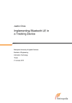
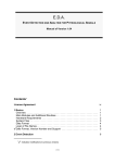
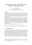
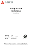
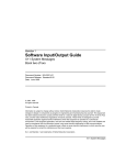
Wireless Multi Sensor Bracelet with Discreet Feedback
Martin Ouwerkerk
Pierre Dandine
Dennis Bolio
Philips Group Innovation
High Tech Campus
Eindhoven, Netherlands
+31 40 2742913
Electrical Engineering
INSA
Lyon, France
+33 6 4792 7699
Philips Group Innovation
High Tech Campus
Eindhoven, Netherlands
+31 6 5278 8395
[email protected]
[email protected]
[email protected]
Rafal Kocielnik
Johanna Mercurio
Mathematics and Computer Science
Eindhoven University of Technology, Den Dolech 2,
5612 AZ Eindhoven, Netherlands
+31 40 2474935
Mobile Life Centre at SICS
Swedish ICT AB, Box 1263
164 29 Kista Sweden
+46 70 2262399
[email protected]
[email protected]
Henk Huijgen
Joyce Westerink
Philips Group Innovation
High Tech Campus
Eindhoven, Netherlands
+31 40 2797307
Philips Group Innovation
High Tech Campus
Eindhoven, Netherlands
+31 6 3162 8153
[email protected]
[email protected]
ABSTRACT
A novel wireless multi sensor bracelet has been developed. The
design choices of the bracelet - based on insights obtained with
a predecessor sensor bracelet -, as well as the rationale for the
choice of sensors, are presented. The hardware and software
architecture are described. An example of obtained sensor data
is shown. The limited battery life of the performance optimized
product software fell short of the one week design target. A
power optimization of the software has been made, which meets
the battery life design target. It is based on current consumption
measurements, and optimized sensor timing. The tradeoffs
between high performance - short battery life, and low
performance - long battery life are analyzed. The learnings from
recent field studies on work-related stress and affective health
are discussed.
sensor bracelet is developed which is comfortable to wear,
acceptable to family, friends, or colleges, and capable of
wireless streaming of measured sensor data, as well as
embedded computation allowing the assessment of emotional
arousal peaks. Based on such assessment a discreet warning
may be given to the wearer in the form of a vibration of the
device.
As part of an Emotion Sensing Platform in 2008 a skin
conductance wristband, the Discreet Tension Indicator (DTI-1)
was made [1]. It featured embedded assessment of the measured
skin conductance, allowing it to detect episodes of high arousal.
A built-in vibration motor can signal this to the wearer in a
discreet fashion. Figure 1 shows a picture of the DTI-1 skin
conductance wristband.
Categories and Subject Descriptors
H.1.2 User/Machine Systems J.3 Life and Medical Sciences Health
General Terms
Performance, Design, Reliability, Experimentation, Human
Factors, Verification
Keywords
Figure 1 Discreet Tension Indicator sensor wristband DTI-1
Ambulatory sensing, unobtrusive, stress, low power technology.
In a book chapter of the Philips Research Book series the
technical aspects of the DTI-1 are described in detail [2]. The
DTI-1 was used in a pilot study on pre-tournament stress
development of elite swimmers. In another pilot study the
development of aggression was monitored in a crisis ward of a
mental hospital [3].
1. INTRODUCTION
Unobtrusive sensing of emotional arousal in a daily life setting
provides insight into what triggers a person, and which settings
or behavior causes most stress. Such information can only be
acquired when the monitoring is done almost continuously. A
In an attempt to develop a consumer lifestyle product utilizing
skin conductance a bracelet prototype was developed for an
internal venture. Details on this work are to be published in a
book chapter [4]. In parallel the electronics of the DTI-1 were
used in a skin conductance wristband for stock traders, called
the Rationalizer [5]. All the above work was done within
Philips.
Table 1. Issues in DTI-1 with solutions in DTI-2 wristband
DTI-1 issue
DTI-2 solution
Zigbee radio dongle needed
Bluetooth transceiver instead of
Zigbee
Outside Philips the group of Rosalind Picard at MIT developed
a skin conductance wristband for sensing of sympathetic
nervous system activation [6]. Based on this work a commercial
version was offered until recently by a company called
Affectiva [7].
Max 25 hours data storage
2 GB microSD card for weeks
of storage
Complicated data readout
procedure
Easy data readout via USB to
any computer
In the framework of research projects sponsored by EIT ICT
Labs that aimed to measure stress in daily life situations funding
became available to develop a successor of the DTI-1. This
paper describes all aspects of this new sensor wristband, the
DTI-2 (see Figure 2).
Max 8 hours battery life
Over one week battery life
(without radio)
Coolflux DSP has limited
availability
MSP430 controller
widespread use
No user interface
Event marker, 2 LED arrays for
user info
Vibration motor buzzer on
outside
Vibration motor buzzer inside
casing
No indicator for radio link
Blue LED signals Bluetooth
activity
No indicator for low battery
Battery voltage shown via LED
arrays
No error handling
Error messages via LED arrays
and in log file
2. DESIGN ASPECTS
No info on context of data
The Discreet Tension Indicator DTI-2 is a sensor wristband,
which offers a number of sensing modalities. The wristband is
designed to be worn by participants in studies and trials.
Light and device temperaturesensor offer context info
Complicated
battery
charging procedure
Battery charging
connector
No date-time awareness
Date/time clock even in off
mode
Figure 2 Novel wireless multi sensor bracelet DTI-2
Experience with ambulatory skin conductance monitoring was
acquired with the DTI-1 wristband. A number of shortcomings
were identified based on issues that came up in the field trials.
In Table 1 these issues are listed along with changes
implemented in the DTI-2.
A skin temperature sensor was added to the DTI-2 to
complement on information of the user state. For example,
Lundqvist et al. [17] found that skin temperature might be
linked to hedonic tone. The skin temperature sensor further
allows triangulation i.e., to use multiple sensor data to describe
a user state or to describe a user state with a higher robustness.
There were additional user requests which were not
implemented in the DTI-2, such as location awareness (GPS),
microphone, heart rate measurement at the wrist, Wi-Fi
connectivity. In most cases these requests were making it
impossible to keep the dimensions, the weight and the battery
life within a useful range.
2.1 Intended use
The DTI-2 device is to be used to monitor at the left or right
wrist of humans: the skin conductance, skin temperature,
ambient temperature, ambient light level, and 3-dimensional
acceleration. The sensor data can be streamed live to a receiving
station via a Bluetooth wireless link. The device is not to be
used as a medical device. Hence no diagnosis or treatment of a
medical illness can or may be performed based on the data
obtained by this device.
via
is
in
USB
2.2 Application requirements
The intended
requirements:
use
leads
to
the
following
application
Physical requirements
- Dimensions, weight, and shape of the device optimized for
ambulatory use.
- Robust casing
- Comfortable fit to wide range of wrist sizes
- Neutral appearance, to avoid drawing attention to the device
Sensor requirements
- Measure the skin conductance at the underside of the wrist
- Measure the 3-D acceleration of the device
- Measure the ambient light level
- Measure the temperature of the device
- Measure the battery voltage at 2 Hz or less
- Date/time awareness with millisecond precision
- Data collection without maintenance for at least one week
- Built-in storage for several weeks of data at highest sampling
rate
User interface requirements
- Event marker with millisecond precision
- User interface for feedback and warning signals
- On/off switching of device
- On/off switching of transceiver
- Wireless connection for real-time streaming of data to a
receiving station without dongle
- Fast USB connection to allow transfer of large amounts of
data
Maintenance requirements
- Easy recharging of the battery in less than 2 hours
- Provide a means to update the firmware
- Provide a means to replace the battery
- Provide a means to replace the data storage card
- Error logging
Regulatory requirements
- Block USB-connector while the device is on the wrist
- Unique serial number
- User manual for end-user in language of end-user
- Documentation of all design and manufacturing information
of the device
- Compliant to safety standard EN 60950-1:2006/A 1:2009/A
1:2010/A12:2011
- Compliant to EN 301 489-1 V1.8.1, EN 301 489-17 V2.1.1
and EN 300 328 V1.7.1
2.3 Implementation
The dimensions of the DTI-2 casing are 39.5 x 12 x 63.5 mm,
which is large enough to contain the battery, the electronics
main board, and the user interface board. The strap is
segmented. To enable the positioning of the skin conductance
electrodes at the underside of the wrist such that one electrode is
at the center, and the other is at the side of the thumb, an
appropriate number of segments can be removed (see Figure 2).
2.4 Electronics
2.4.1 Flexible main printed circuit board
The casing of the DTI-2 has a shape that curves around the wrist
(see Figure 2). The main PCB has been manufactured as a flex
foil with two bending zones, to use the full length of the casing.
The two segments at the ends of the flex are fitted with a
stiffener to improve mechanical stability. The presence of the
lithium polymer battery stabilizes the central part of the flex,
when mounted in the casing. On one side of the flex, the USB
connector is placed. The opening in the casing for the USB
cable is positioned behind the hinge. To connect the USB cable
the hinge needs to be turned fully to the inside of the strap. This
safeguards that the USB cable cannot be connected while a
person is wearing the DTI-2 on the wrist, which is a safety
requirement. The Bluetooth transceiver (Panasonic PAN1325) is
a complete module consisting of the electronics and ceramic
antenna. The module is placed on the other end of the main
printed circuit board. When the DTI-2 is strapped on a wrist in
the prescribed position, this side of the main PCB is on the side
of the wrist which is pointing away of the torso. Signal
absorption by human tissue is minimized in this way.
The controller MSP430BT5190 from Texas Instruments is a
dedicated type for use in combination with the PAN1325
transceiver and Mindtree software stack [12]. In terms of lowpower capabilities it is comparable to the rest of the MSP430 5series, and particularly comparable to the MSP430F5438A,
which has excellent low-power capabilities, such as user defined
frequencies, various sleep states, watchdog timer.
The data storage is done on a 2 GB microSD card, which can be
replaced when necessary. An Alcor AU6431-JCF controller
takes care of the communication via the USB cable, causing the
card to mount as a drive on a computer, when the DTI-2 is
connected.
The electronics consists of four interconnected printed circuit
boards (PCBs): the user interface board, the sensor board, the
main board, plus a patch board to allow battery charging via the
USB connector.
In the block diagram shown in Figure 3 the PCBs are shown as
light blue rectangles, the patch board, which connects the +5V
USB pin to the battery, is omitted.
Figure 4 Assembly of the DTI-2 sensor wristband showing
the user interface board, the patch board, the main PCB, the
lithium battery, the vibration motor, and the button pads.
2.4.2 Sensors
The low power 3-axes accelerometer sensor type LIS331DLH
made by STMicroelectronics is placed onto the main PCB.
Figure 3 Electronics diagram of the DTI-2 sensor wristband
The device temperature sensor AD7415 Analog Devices and the
ambient light sensor TSL2561T from Taos are placed on the
user interface PCB. A lens positioned above the sensor diodes of
the ambient light sensor offers a wide angle of view from the
top of the casing. By setting the integration time the right
balance between sensitivity and power saving can be chosen.
The sensor has two light sensitive diodes, one peaking in the red
(at 640 nm), and another in the near infra red (940 nm).
When a skin temperature sensor was to become part of the DTI2 bracelet it was decided to create a separate printed circuit
board for the skin conductance sensor and the skin temperature
sensor. An advantage of this configuration lies in the local
filtering, amplification and digitization of the skin conductance
signal. The pickup of electromagnetic noise can be minimized
this way. Only digital signals at 3.3V have to be communicated
from the base of the wrist to the main printed circuit board.
The skin temperature sensor is an optical sensor. The medical
grade Melexis 90615 SSG-DAA infrared thermometer was
chosen, which offers a high 0.02 degree resolution combined
with a low current consumption. The device can be put in a
sleep mode to save energy. After resuming operation it takes
300ms to obtain valid skin temperature data. Due to settling, in
the first minute after putting the sensor on the wrist the
temperature readouts are too high as can be seen in Figure 5.
After this period the readings are accurate. The sensor is located
on the underside of the wrist in-between the two skin
conductance electrodes (see Figure 2).
The skin conductance sensor electronics uses a DC current
through the skin. The skin contact electrodes for the skin
conductance sensor are replaceable 0.95cm diameter eyelets
made by Micron products Inc., which are positioned at the
underside of the wrist. In [11] the validity of this location as a
position where emotion induced skin conductance signals can be
measured is described.
A stable 1.2 V reference voltage causes a current to flow
through the skin, a 1 kΩ safety resistor, and two 10MΩ
reference resistors. The voltage drop over the skin plus the
safety resistor is amplified 2.8-fold, and filtered over a 2nd
order low-pass Butterworth filter before analog to digital
conversion by a 16-bit Analog Devices AD7685 ADC. The
ADC uses a stable 3 V reference voltage.
Figure 5 Sensor output of the DTI-2, showing a 12 hour
period. The top trace shows the skin conductance, the trace
below that shows the skin temperature, the third trace
visualizes the output of the motion sensor, and the bottom
trace the ambient light sensor readings. Around 19h00 the
bracelet was taken off the wrist for about 30 minutes.
In Figure 5 the result of 12 hours of data collection of the main
sensors is shown in four graphs.
2.4.3 User interface electronics
The user interface of the DTI-2 consists of 4 buttons, two rows
of eight LEDs plus some signaling LEDs. The buttons are meant
for switching the device on/off, switching the Bluetooth radio
on/off, setting an event marker, and showing the level of the
battery or the level of the skin temperature or skin conductance.
3. Software
The architecture of the embedded software is organized in
layers, as shown in Figure 6. The layers allow a separation of
functionality, which facilitates local development, debugging
and maintenance. The layers are decomposed in a number of
software components, shown in Figure 7, each with a clear and
upfront defined interface and function.
FreeRTOS is the selected operating system for the embedded
software. Beside the Mindtree SDK tasks, also other tasks are
created for scheduling the sampling and storing the data.
Figure 6 Layered software architecture
For storage of measurement data on the microSD card, a FAT32
file system is used. The file system contains the measurement
data, logging data, and in some cases a settings file with a
device configuration.
The software development process used an incremental
approach. At each bi-weekly increment, well defined parts of
the functionality have been delivered. Using this approach the
software development could be tracked and steered in an agile
approach. Each increment was finalized with a delivery.
A CR/PR system [14] is used for change control. New features
of each increment and discovered problems are entered in this
CR/PR system. This system is linked directly to the software
archive [14] to provide traceability through the entire
development process.
For building and testing the intermediate software versions, the
Jenkins continuous integration server [15] has been used.
Jenkins is an open and widely used integration server and it was
already successfully used in other projects. Using the integration
server the embedded software build process has been automated.
After each build, regression tests are run automatically.
The software development process is designed to accelerate
future medical certification of the product software (e.g. CR/PR
management, traceability, automated testing).
Parallel to the software development a separate power
optimization track was started which is detailed in section 4.
After determining the optimum balance between power saving
and other requirements the power optimizations will be
integrated in the product software.
4. POWER SAVING
Figure 7 Software components and their release number
Product features (e.g. detection algorithms for emotional events,
see [1]) and support for additional hardware sensors can be
added by replacing or adding software components.
Requests from end users for adaptation of the software to the
needs of their studies/trials are accommodated in the application
layer. The service layer provides generic functional building
blocks (e.g. temperature service, communication service) to the
application layer. It also provides an abstraction of the lower
layers, like sensor layer and the storage subsystem. The driver
layer contains the sensor specific drivers. In this layer for
example the driver for a specific make and model of a
temperature sensor, but also drivers for the user interface
components can be found. The HAL and platform layer contain
the controller specific part of the embedded software like I2C
and SPI and controller pin definitions. To port the software to
another type of controller or even a PC-based platform, these
layers have to be rewritten.
The Mindtree EtherMind Bluetooth SDK [12] is used to control
MSP430BT5190 in combination with PAN1325 module. The
Mindtree SDK uses FreeRTOS [13] as operating system. For
The DTI-2 is a wearable device, which is used in trials and
studies. In these circumstances it is often desirable that the
recharging of the battery occurs only once per week. With the
product software described in section 3 a battery life of about 30
hours is reached. This was significantly lower than the target
battery life of one week (see Table 1). It was undertaken to find
out which software changes were needed to reach the target
battery life, and what the consequences would be for flexibility
in choosing the sampling rate, and the timestamp accuracy.
Based on the variations in the signal the optimal sampling rate
for the various sensors can be determined (see Table 2). This is
the lowest sampling rate where no useful information gets lost.
For slow varying parameters, such as the device temperature a
sampling rate of 0.1Hz can be sufficient, whereas for the 3D
accelerometer already at 10Hz a small fraction of the motion
information gets lost.
The DTI-2 uses the FreeRTOS to schedule all tasks, such as
data sampling, data storage, wireless streaming, and user
interface. In order to accommodate the different optimal
sampling rates of the various sensors a separate task can be
defined for each sensor. Such a task can also switch the sensor
off when idle to save power, and to switch it on taking a warmup time into account to get an accurate reading. This offers a
good data sampling rate flexibility of the system together with
optimized power consumption.
This optimized scheme was implemented, and the current
consumption measured. The results are shown in Table 2. The
total average current consumption turned out to be lower when
the device was not actively used, i.e. with the skin conductance
electrodes not in skin contact. The active filter, which removes
noise coming from 60 or 50Hz mains uses about 0.5 mA extra
current when the device is worn by a person.
Table 2 Contributions to average current consumption of
power optimized scheme
Regular skin
conductance
(0.2 µS)
Device not in skin
contact (open
circuit)
Idle task
0.195 mA
0.195 mA
Accelerometer @ 10
Hz
0.258 mA
0.258 mA
Device Temperature
sensor @ 0.2 Hz
0.001 mA
0.001 mA
Ambient light sensor
@ 0.2 Hz
0.003 mA
0.003 mA
Skin Temperature
sensor @ 0.2 Hz
0.145 mA
0.145 mA
Skin Conductance
sensor @ 10 Hz
1.080 mA
0.580 mA
Data storage @ 10 Hz
0.740 mA
0.740 mA
Total average current
2.422 mA
1.922 mA
Contribution to
average current
consumption
Under usage conditions such as occur in studies and trials (i.e.
continuous wearing the bracelet) the 2.4mA average current
combined with the 400mAh battery offers a over a week of
battery life. The low C-rate (1/175) allows the extraction of
about 425mAh from the battery. The design target of Table 1 is
met.
The contributions of the various processes to the average current
consumption can be visualized in a pie diagram, which is shown
in Figure 8.
multiple of 10ms. Using this approach, a complicated situation
is created: for example starting one sensor at a certain time, wait
300ms, take the data, at the same time powering up another
sensor at different moment to be sure that the simultaneous data
collection does not occur (which may cause an unwanted delay).
In the present firmware, the sensors are on all the time, causing
the timing accuracy to be very good, but the power efficiency is
poor.
Figure 8 Pie diagram showing the contributions of the
various components and processes to the total current
consumption (2.422 mA) in the optimized low power mode
A solution that combines a high power efficiency and a good
time accuracy is to do everything in one task, and each of the
sensors is switched on at a precise moment, with always the
same relative time lag with the other sensors. This is done in the
task for temperatures and luminance in the power consumption
optimized software. This, however, causes the sampling rate
flexibility to decrease, as changing the sampling rate of one
particular sensor is affecting the timing of all other events.
4.1 Trade offs
The problem using a RTOS with high number of tasks is that the
execution of some of the tasks can be delayed, so the accurate
timing of the data sampling is negatively affected.
In order to save RAM collected sensor data is stored in the flash
memory of the MSP430, prior to batch writing it onto the
microSD card. Erasing a section of the local flash takes 250 ms
during which it cannot be used. This can cause a significant
delay in storing the sensor data, causing an error of up to 250 ms
in the timestamp.
Some of the end users need a very high time accuracy, for
detecting the activity of the user with the accelerometer output
for example. Then the accuracy of the timestamps is vital, and
this kind of power saving has to be avoided
A solution to avoid multiple tasks is to do the data collection
and storage in a single FreeRTOS task, as it is done in the
product software described in section 3. If the task is running
with a timer at 100Hz for example, sampling the accelerometer
at 10Hz is equivalent to skipping this step on the task 9 times
out of 10. Changing the rate requires only to change the skip
counter. Note that this requires the time between samples to be a
Figure 9 Time accuracy vs. Power efficiency vs. Flexibility.
All parameters increase when moving away from the origin.
To have a combination of very good time accuracy, a good
flexibility, and good power efficiency is impossible to achieve.
Based on the end user needs the programmers of the application
layer described in section 3 have to find a good compromise
between these 3 parameters.
In general, it is probably better to reduce the sampling rate
flexibility a bit, enabling the reduction of the average
consumption of the production software. This will lead to a
longer battery life. In Figure 9 the power optimized software
solution is represented in blue (Low power software), the
product software in red, and an ideal software in green. Tailored
software solutions for different end-user needs, such as will be
discussed in the next section, shall always be necessary.
members of an elite orienteering team, office workers at
Ericsson, female individuals between 25 and 55 years of age.
Preliminary results indicate the people generally do accept the
data as representing themselves, and on several occasions are
the basis for enhanced awareness of their lifestyle. Most of the
users were therefore motivated to keep on wearing the DTI-2
device for the duration of the test, even though they found that
the DTI-2 did not look fancy at all. Some of them countered this
disadvantage by (temporally) enhancing the DTI-2 with glue-on
trinkets (see Figure 11).
5. DISCUSSION
The DTI-2 sensor bracelet is meant as an improvement of its
predecessor DTI-1. In total 160 complete devices have been
produced by Philips Innovation services (PInS). Whether the
device is meeting expectations can only be judged from
experiences in field use. The DTI-2 is approved to be used in a
number of healthcare-related studies. One of these studies is the
aggression prevention study Watch It!, aiming at early detection
of imminent aggression in crisis wards of mental hospitals, and
forensic psychiatry wards, and a follow up on the pilot study
reported in [3].
In between the healthcare and lifestyle domain is the IET-ICT
funded study led by the TU/e on burnout prevention of school
teachers [9]. At the time of writing the pilot has been completed.
It assured the feasibility of the test set-up, the enthusiasm of the
pilot participants, and at least some relevancy of the gathered
data. The full scale study on 30 persons is about to begin.
The sensor data is collected batch wise from the microSD cards
and post processed as shown in Figure 10, which is reproduced
from [9]. The end result of the processing are banded colors,
representing more or less episodes with more or less tension,
which are compared with the teaching roster of the participant.
Figure 10 Data processing of DTI-2 data from teachers at
risk of burnout obtained by the Stress@Work project [9].
More in the lifestyle domain is the IET-ICT funded study led by
the Swedish Institute of Computer Science called WeCare [10],
in which the emphasis is on communication of daily arousal
data to the wearer of the DTI-2 bracelet via an Android app.
There were some 30 participants, distributed over 3 groups:
Figure 11 Example of DTI-2 appearance “enhancements” by
participants
In Figure 12 an Android phone screenshot is shown of several
hours of DTI-2 data that was streamed via the Bluetooth link.
Higher arousal causes the coloration to shift towards warmer
colors (orange/red), whereas lower arousal is depicted by cooler
colors (green/blue). The spiral allows the visualization of a
chosen section of history (in this case 6 hours). The user can tag
emotional events, which show as pins in the spiral. The
acceleration shows as a white jagged line on the inside of the
spiral, with large peaks indicating vigorous motion.
Figure 12 Affective Health User Interface, that runs as an
app on an Android phone. It shows the skin conductance
history as a colored spiral, and the motion sensor output as a
jagged white edge of the spiral. User defined tags of
emotional moments can be entered and show as pins on the
spiral [10].
In the Affective Health study all data was streamed real time to
the Android mobile phone of the participant. The power
intensive use decreased battery life down to a single day. In
Figure 13 an overview of more than 3 weeks of collected data
for a participant is shown.
[2] Ouwerkerk, M. 2011. Unobtrusive Emotions Sensing in
Daily Life. Chapter 2 in: Westerink, J., Krans, M,
Ouwerkerk, M. Sensing Emotions – The Impact of Context
on Experience Measurements, Philips Research Book
Series Volume 12, Springer, 21-40.
[3] Kuijpers, E., Nijman, H., Bongers, I. M. B., Lubberding,
M., Ouwerkerk, M. 2012. Can mobile skin conductance
assessments be helpful in signalling imminent inpatient
aggression?. Acta Neuropsychiatrica, 24 (2012), 56–59.
[4] Westerink, J.H.D.M., van Beek, W.H.M., Daemen, E.M.L.,
Janssen, J.H., de Vries, J.J.G., Ouwerkerk, M., 2013. The
Vitality bracelet: bringing balance to your life with
psychophysiological measurements, , Fairclough, SH,
Gilleade K (ed) Advances in Physiological Computing,
Springer-Verlag London (in press).
[5] Djajadiningrat, T., Geurts, L., Munniksma, P.-R.,
Christiaansen, G., de Bont, J. 2009. Rationalizer: an
emotion mirror for online traders. Proceedings of the 5th
International Workshop on Design and Semantics of Form
and Movement 39-48.
[6] Poh, Ming-Zher, Swenson, N.C., Picard, R.W., 2010. A
Wearable Sensor for Unobtrusive, Long-Term Assessment
of Electrodermal Activity. IEEE Transactions on
Biomedical Engineering, 57, 5 (May 2010), 1243-1252.
Figure 13 Over 3 weeks of data collected in the Affective
Health study: the top trace shows the skin conductance, the
middle trace the 3D accelerometry, and the bottom trace the
battery voltage.
[7] http://www.qsensortech.com
From the battery voltage trace it can be seen that never in the
duration of the study a low battery condition (>3 V) was
experienced. The choice to use Bluetooth for wireless data
transfer was driven by the availability in mobile phones. A
transition to Bluetooth low energy or ANT can be implemented
as soon as the mobile phone software and hardware becomes
available, by replacing the current Panasonic PAN1325A by a
pin compatible PAN1323 module. This is expected to
dramatically increase battery life during continuous wireless
data streaming.
[9] Kocielnik, R., Sidorova, N., Maggi, F. M., Ouwerkerk, M.,
Westerink, J. H. D. M., 2013.Smart Technologies for
Long-Term Stress Monitoring at Work, submitted to
the26th IEEE International Symposium on ComputerBased Medical Systems.
The DTI-2 bracelet continues to be used in trials and studies.
The acceptance of skin conductance measured at the wrist is
growing, also indicated by a mentioning of the DTI-1
in the recently revised standard book on skin conductance [16].
[8] van der Zwaag, M.D., Janssen, J.H., Westerink, J.H.D.M.
2013. Directing Physiology and Mood through Music:
Validation of an Affective Music Player. IEEE
Transactions on Affective Computing 4, 1 (2013) 57-68.
[10] Sanches, P., Höök, K., Vaara, E., Weymann, C., Bylund,
M., Ferreira, P., Peira, N., Sjölinder, M. 2010. Mind the
body!: designing a mobile stress management application
encouraging personal reflection. In Proceedings of the 8th
ACM conference on designing interactive systems (2010).
ACM, New York, NY, 47-56.
At the moment of writing the most promising option for the
DTI-2 is the need for ambulatory sensors in psychiatry that can
shed light on the mental state of crisis ward patients. [3].
[11] van Dooren, M., de Vries, J.J.G., Janssen, J.H., Emotional
sweating across the body: Comparing 16 different skin
conductance measurement locations, Physiology &
Behavior, 106 (2012) 298-304.
6. ACKNOWLEDGMENTS
[12] http://processors.wiki.ti.com/index.php?title=File:MSP430
BT5190_CC2560_Developers_Guide.pdf&limit=50
Our thanks to EIT ICT Labs who in part subsidized this work, to
Richard van der Wolf of PInS for the electronics design, Tim
Bakker for software writing and testing, Kris Godzwon for
project management.
[13] FreeRTOS: http://www.freertos.org/
7. REFERENCES
[15] Jenkins: http://jenkins-ci.org/
[1] Westerink, J.H.D.M., Ouwerkerk, M., de Vries, J.J.G., De
Waele, S., van den Eerenbeemd, J., van Boven, M. 2009.
Emotion measurement platform for daily life situations.
Proceedings Volume I, International Conference on
Affective Computing & Intelligent Interaction, ACII (Sep.
2009), Amsterdam, The Netherlands, 217-222.
[16] Boucsein, W. 2012 Electrodermal Activity 2nd Ed.,
Springer Science+ Business Media LLC, New York.
(2012) 108-109.
[14] IBM Rational Synergy and Change suite http://www01.ibm.com/software/rational/products/synergychangesuite
/
[17] Lundqvist,L.-O., Carlsson, F.,Hilmersson, P., Juslin, P.N.,
Emotional responses to music: experience, expression, and
physiology, Psychology of Music 37 (2009) 61-90.