1
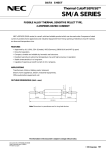
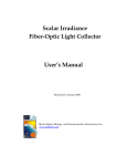
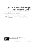
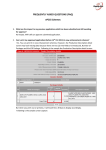
DATA SHEET
Thermal Cutoff SEFUSETM
SM/B SERIES
FUSIBLE ALLOY THERMAL SENSITIVE PELLET TYPE,
1 AMPERE RATED CURRENT
NEC's SEFUSE (SM/B series) is a small, solid and reliable product which can be used under 1 ampere of rated
current. It protects home appliances and industrial equipment from fire by opening of electrical circuit if it senses
an abnormal temperature rise.
FEATURES
™ Approved by UL (USA), CSA (Canada), VDE (Germany), BEAB (UK) and MITI (Japan)
™ One shot operation.
™ Compact, durable and reliable by hermetic seal structure.
™ Excellent sensitive to abnormal temperature rise and high accuracy in operation.
™ Stable characteristics in a long-term.
™ Capable of opening at cutoff current of AC 1 ampere.
APPLICATIONS
Transformers, Motors,
Electric home appliances, Electric Industrial equipments,
Office automation equipments, etc.
39.5(69.5)
6
φ 0.53
φ 0.53
φ 2.0
OUTLINE DIMENSIONS (Unit : mm)
39.5(69.5)
85(145)
Note: Dimensions in parentheses are for long lead devices.
The information in this document is subject to change without notice.
Document No. EM0254EJ1V0DS00
Date Published February 1997 M
Printed in Japan
©
1997
SM/B SERIES
TYPE NAME DESIGNATION
SM
130
B
0
Lead Length (0 : standard lead type, 1 : long lead type)
Series Name (SM/B series)
Operating Temperature
Type Name (SM type)
MARKING
SEFUSE
SM130B0
MITI
Approved Mark
Brand Name
Type Name
Production Control No. ∗
Tf135˚C
Rated Functioning Temperature
1 A 250V~
Rated Current
Rated Voltage
∗ Designation of Production Control No.
(example)
6 7 0
Sub-Lot No.
Production month (1 to 9 as Jan. to Sep. and X, Y, Z as Oct., Nov. and Dec.)
Production year (last two figures of A. D.)
STANDARD RATINGS
1)
Part
Number
Rated
Operating
Functioning
Temperature
Temperature
TH
Th
TC
TM
Tm
Safety Standard
Rated
Current
Rated
Voltage
UL
CSA
VDE
BEAB
E71747
LR
6778.2–
C0557
52330
4510–
SM095B0
100 ˚C
95+5/–0 ˚C
65 ˚C
115 ˚C
SM110B0
115 ˚C
110±2 ˚C
80 ˚C
125 ˚C
1 Aac
250 Vac
33–466
SM126B0
131 ˚C
126±2 ˚C
96 ˚C
140 ˚C
(Res.)
(Res.)
SM130B0
135 ˚C
130±2 ˚C
100 ˚C
145 ˚C
SM145B0
150 ˚C
145±2 ˚C
115 ˚C
160 ˚C
33–468
SM129B0
130 ˚C
129+0/–5 ˚C
96 ˚C
140 ˚C
33–467
33–472
33–467
1009
Notes : 1) The type names are for standard lead. When long lead type is required, change the last number “0” to “1”.
2
SM/B SERIES
Definition of Terms
●
Rated Functioning Temperature
Rated functioning temperature is the operating temperature of the thermal cutoff, measured using the method
specified in the safety standard. In Electrical Appliance and Material Control Law of Japan, case operation
should be within the specified operating temperature range of ± 7 ˚C. In standards that comply with the IEC
standard (such as UL, CSA, VDE, BEAB), it is called the rated functioning temperature, and should operate
within the prescribed temperature range of +0/–10 C.
It is represented by the symbol TF in the UL standard, and by the symbol Tf in the CSA, VDE and BEAB
standards.
In SEFUSE, a temperature that complies with both standards is set as the rated functioning temperature, and
is indicated on the body of the thermal cutoff.
●
Operating Temperature
Operating temperature is the operating temperature range when the thermal cutoff is made to operate inside
a constant temperature oven whose temperature is raised at the rate of 1 ˚C/min. while a detection current of
100 mA or lower is applied.
The operating temperature is a standard set by NEC and is not specified by a safety standard.
●
TH, Th. Tc (Holding Temperature)
Holding temperature is the maximum temperature at which, when applying a rated current to the thermal
cutoff, the state of conductivity is not changed during 168 hours.
It is represented by the symbol TH in the UL standard, Th in the CSA standard, and Tc in the VDE and BEAB
standards.
●
TM, Tm (Maximum Temperature Limit)
Maximum temperature limit is the maximum temperature for which conductivity does not occur again after
thermal cutoff operation.
It is represented by the symbol TM in the UL standard and by Tm in the CSA, VDE and BEAB standards.
●
Rated Current
Maximum alternating current that can pass through thermal cutoff
●
Rated Voltage
Maximum circuit voltage for thermal cutoff
3
SM/B SERIES
Performance Data
SM/B Series
Temperature Rise
Response Time
10
9
SM095B0
SM110B0,SM126B0,SM130B0
SM145B0
,
,
,
,
,, ,,,,,
,
,
,
,
,
,
,,,,,,,,,,,,
, , ,,
30
Time for opening after immersion
into oil (seconds)
Temperature Rise (˚C)
8
7
6
5
4
3
2
20
10
1
0
0
1
2
SM095B0
SM110B0
SM125B0
SM130B0
SM145B0
10
20
30
40
50
Temperature Difference (˚C)
(oil temp. minus operating temp.)
3
Pass-through Current (A)
Initial Characteristics
SM145B0
SM130B0
SM126B0
SM110B0
SM095B0
High Temperature Storage Test
146
106
3.0
4.0
145
105
2.0
3.5
144
104
1.0
3.0
–5
130
106
3.0
4.7
+5
129
105
2.0
4.6
128
104
1.0
4.5
–5
127
106
3.0
4.8
+5
126
105
2.0
4.6
125
104
1.0
4.4
–5
112
106
3.0
4.7
+5
111
105
2.0
4.6
110
104
1.0
4.5
98
106
3.0
9.5
97
105
2.0
9.0
96
104
1.0
8.0
SM145B0
SM130B0
SM126B0
SM110B0
4
Withstand Voltage
Operating
Internal
Resistance after
after Operation
Temperature
Resistance
Operation
(kV)
(˚C)
(mΩ/25 mm)
(MΩ)
0
@110˚C
0
@106˚C
0
@90˚C
0
–5
@75˚C
+5
SM095B0
0
–5
Insulation
Part
Number
@125˚C
+5
Part
Number
Change of
Operating
Temperature
(˚C)
0 10
100
1,000
Time (Hours)
10,000
SM/B SERIES
Cautions
This section describes cautions designed to protect the performance of the thermal cutoff, Be sure to read and
fully understand these cautions.
To obtain full performance from the thermal cutoff, it is necessary for the customer to appropriately store
the thermal cutoff, design appropriate circuits for the application, and perform evaluations, mounting and
testing as necessary. Problems arising from the inappropriate execution of the above are the responsibility
of the customer, and NEC declines any and all responsibility.
Design Cautions
●
Do not use this device for purposes other than as a thermal cutoff.
The thermal cutoff is designed to detect abnormal rises in temperature and break circuits if needed. It is not
a current fuse that cuts excess current. If used as a current fuse, the SEFUSE may malfunction.
●
Do not use this device in aerospace equipment, aeronautical equipment, nuclear reactor control systems, Iife
support equipment or systems, transportation machinery engine control or safety-related equipment.
This device is designed for use in household electric appliance, office automation equipment, audio and video
equipment, computer communications equipment, test and measurement equipment, personal electronic
equipment and transportation equipment (excluding engine control).
●
The customer should select the proper thermal cutoff device, mounting location, and mounting method as
appropriate for each application.
Verify whether the chosen selections are appropriate by repeatedly testing the final design for thermal cutoff
under normal conditions as well as under predicted maximum abnormal conditions.
●
Make designs so that the temperature of the body of the thermal cutoff does not exceed the temperatures
shown in Table 1.
If, these temperatures are exceeded on a regular basis, the thermal cutoff may start operating only at temperatures lower than the normal operating temperature. Malfunctions may also occur. Even if the thermal
cutoff's operating temperature is exceeded, it may malfunction.
Table 1.
Type Name
Body Temperature
SM095B0, SM095B1
SM110B0, SM110B1
SM126B0, SM126B1
SM129B0, SM129B1
SM130B0, SM130B1
SM145B0, SM145B1
75˚C
90˚C
106˚C
106˚C
110˚C
125˚C
5
SM/B SERIES
●
The body temperature of the thermal cutoff becomes higher as current passes through and might rise higher
than the ambient operating temperature (see test data). The temperature may rise even higher depending on
the mounting method and other conditions. Therefore, after mounting the thermal cutoff under the same
conditions you would use for the actual application, run the final product and measure the body temperature
of the thermal cutoff.
●
Use the thermal cutoff with a voltage and current level lower than the rated level.
If the thermal cutoff is used with a voltage or current level higher than the rated level, the body of the thermal
cutoff may be destroyed.
●
Do not use the thermal cutoff in water, organic solvents or other liquids, or environments containing sulfurous
acid gas, nitrous acid gas, or high humidity. Doing so will cause deterioration of the sealing resin, the thermal
cutoff to operate at lower-than-operating temperatures, or malfunctions to occur. Also, the thermal cutoff may
not operate even if its operating temperature is exceeded.
Lead wire process
●
When bending the lead wire, in order not to apply excessive pressure to the root of the lead wire, secure the
lead wire cIose to the case and bend the part beyond the secured section,
3 mmor more
,,,,,
,,
,,,,,
,,
,,,,,,
,,,,,,
Secured
Secured
The lead wire should be bent at a distance 3 mm or more from the body of the fuse, and should not be twisted.
●
The tensile strength applied to the lead wire should be 1kg or ress for the SM type thermal cutoff.
●
The strength applied to the body of the thermal cutoff should be 5 kg or less for the SM type thermal cutoff.
5 kgf max.
φ 0.8 steel wire
Mounting
SEFUSE can be mounted by soldering, caulking, or welding.
●
If soldering, note that the thermal cutoff may not function because of excessive solder temperature.
To prevent such malfunctions, you can hold the lead near the case using a tool and solder for short intervals
at a time, allowing the heat to escape.
Another effective method is to use a lower solder temperature and to solder at a location that is distant from
the case.
6
SM/B SERIES
●
If caulking or welding, be careful to keep the resistance value of the connecting section low.
If the connecting section has a high resistance value, the passing current may generate an abnormally high
temperature that will cause the thermal cutoff to operate (break the circuit).
●
It is recommended that the connecting position at the lead of resign-sealed side should be 5 mm or more from
the body of the thermal cutoff.
5 mm or more
●
5 mm or more
Connecting position
After mounting the thermal cutoff, be careful not to apply force that may pull, push or twist the lead wires.
Recommendation
●
Be careful when mounting the thermal cutoff because external force, heat, or a harmful atmosphere (containing excessive humidity or sulfurous acid gas) may damage the characteristics of the thermal cutoff. If applicable, it is recommended to warn general consumers who are not aware of the usage cautions for the thermal
cutoff not to mount, remove or replace the thermal cutoff through a note to this effect in the user's manual and
other related material.
If you desire any clarifications or explanations regarding these cautions, please call an NEC sales
representative.
The values contained in this document were obtained under certain testing conditions at NEC. They are not
guaranteed and are for reference only.
7
SM/B SERIES
No part of this document may be copied in any form or by any means without the prior written consent of
NEC Corporation.
NEC Corporation does not assume any liability for infringement of patents, copyrights or other intellectual
property rights of third parties by or arising from use of a device described herein or any other liability arising
from use of such device. No license, either express, implied or otherwise, is granted under any patents, copyrights or other intellectual property rights of NEC Corporation or others.