1
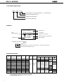
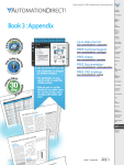
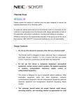
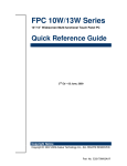
DATA S H EET
Thermal Cutoff SEFUSETM
SM / A SERIES
FUSIBLE ALLOY THERM AL SENSITIVE PELLET TYPE,
2 AM PERES RATED CURRENT
NEC's SEFUSE (SM /A series) is a sm all, solid and reliable product w hich can be used under 2 am peres of rated
current. It protects hom e appliances and industrial equipm ent from fire by opening of electrical circuit if it senses
an abnorm al tem perature rise.
FEATURES
™ Approved by UL (USA), CSA (Canada), VDE (Germ any), BEAB (UK) and M ITI (Japan)
™ One shot operation.
™ Com pact, durable and reliable by herm etic seal structure.
™ Excellent sensitive to abnorm al tem perature rise and high accuracy in operation.
™ Stable characteristics in a long-term .
™ Capable of opening at cutoff current of AC 2 am peres.
APPLICATIONS
Transform ers, M otors, Battery packs, Solenoid,
Electric hom e appliances, Electric Industrial equipm ents,
Office autom ation equipm ents, etc.
38(68)
9
φ 0.6
φ 0.6
φ 2.5
OUTLINE DIM ENSIONS (Unit : mm)
38(68)
85(145)
Note: Dim ensions in parentheses are for long lead devices.
The information in this document is subject to change w ithout notice.
Docum ent No. EM 0253EJ2V1DS00
Date Published April 1998 M
Printed in Japan
©
1997
SM / A SERIES
TYPE NAM E DESIGNATION
SM
130
A
0
Lead Length (0 : standard lead type, 1 : long lead type)
Series Nam e (SM /A series)
Operating Tem perature
Type Nam e (SM type)
M ARKING
SEFUSE
SM130A0
M ITI
Approved M ark
Brand Nam e
Type Nam e
Production Control No. ∗
Tf135˚C
Rated Functioning Tem perature
2 A 250V~
Rated Current
Rated Voltage
∗ Designation of Production Control No.
(example)
8 7 0
Sub-Lot No.
Production month (1 to 9 as Jan. to Sep. and X, Y, Z as Oct., Nov. and Dec.)
Production year (last figure of A. D.)
STANDARD RATINGS
1)
Type
Nam e
Rated
Operating
Functioning
Temperature
Temperature
TH
Th
TC
TM
Tm
SM 065A0
70 ˚C
65±2 ˚C
40 ˚C
80 ˚C
SM 072A0
76 ˚C
72+3/–2 ˚C
46 ˚C
100 ˚C
SM 095A0
100 ˚C
95+5/–0 ˚C
65 ˚C
115 ˚C
Rated
Current
Rated
Voltage
Safety Standard 2)
UL
CSA
VDE
BEAB
33–528
3)
33–466
E71747
LR
6778.2–
52330
4510–
C0600
SM 110A0
115 ˚C
110±2 ˚C
80 ˚C
125 ˚C
SM 126A0
131 ˚C
126±2 ˚C
96 ˚C
140 ˚C
SM 129A0
130 ˚C
129+0/–5 ˚C
96 ˚C
140 ˚C
SM 130A0
135 ˚C
130±2 ˚C
100 ˚C
145 ˚C
SM 134A0
139 ˚C
134±2 ˚C
–
–
SM 145A0
150 ˚C
145±2 ˚C
115 ˚C
160 ˚C
33–468
SM 164A0
169 ˚C
164+3/–2 ˚C 133 ˚C
180 ˚C
33–470
SM 182A0
187 ˚C
195 ˚C
33–556
182±2 ˚C
152 ˚C
2 Aac
250 Vac
(Res.)
(Res.)
1007
33–472
33–467
Notes :1) The type nam es are for standard lead. When long lead type is required, change the last num ber “ 0” to “ 1” .
2) The colored place m eans recognized safety standard.
3) Under application for C-UL
2
SM / A SERIES
Definition of Terms
●
Rated Functioning Temperature
Rated functioning tem perature is the operating tem perature of therm al cutoffs, m easured using the m ethod
specified in the safety standard. In Electrical Appliance and M aterial Control Law of Japan, case operation
should be w ithin the specified operating tem perature range of ± 7 ˚C. In standards that com ply w ith the IEC
standard (such as UL, CSA, VDE, BEAB), it is called the rated functioning tem perature, and should operate
w ithin the prescribed tem perature range of +0/–10 C.
It is represented by the sym bol TF in the UL standard, and by the sym bol Tf in the CSA, VDE and BEAB
standards.
In SEFUSE, a tem perature that com plies w ith both standards is set as the rated functioning tem perature, and
is indicated on the body of the therm al cutoff.
●
Operating Temperature
Operating tem perature is the operating tem perature range w hen the therm al cutoff is m ade to operate inside
a constant tem perature oven w hose tem perature is raised at the rate of 1 ˚C/m in. w hile a detection current of
100 m A or low er is applied.
The operating tem perature is a standard set by NEC and is not specified by a safety standard.
●
TH, Th. Tc (Holding Temperature)
Holding tem perature is the m axim um tem perature at w hich, w hen applying a rated current to the therm al
cutoff, the state of conductivity is not changed during 168 hours.
It is represented by the sym bol TH in the UL standard, Th in the CSA standard, and Tc in the VDE and BEAB
standards.
●
TM , Tm (M aximum Temperature Limit)
M axim um tem perature lim it is the m axim um tem perature for w hich conductivity does not occur again after
therm al cutoffs operation.
It is represented by the sym bol TM in the UL standard and by Tm in the CSA, VDE and BEAB standards.
●
Rated Current
M axim um alternating current that can pass through the therm al cutoff and that the therm al cutoff can cut off
in safety and reliability.
●
Rated Voltage
M axim um circuit voltage that the therm al cutoff can cut off in sefety and reliability.
3
SM / A SERIES
Performance Data
SM / A Series
Temperature Rise
Response Time
(˚C)
6
4
,
,
,
,
,
,
,
,,,,,,,
,,,,,,,,,,,,,,
,,,,,,,,
,,
30
SM 095A0
SM 110A0
SM 126A0
SM 130A0
SM 145A0
Tim e for opening after im m ersion
into oil (seconds)
Tem perature Rise (˚C)
5
3
2
1
SM 095A0
SM 110A0
SM 126A0
SM 130A0
SM 145A0
20
10
0
0
1
2
Initial Characteristics
SM 130A0
SM 126A0
SM 110A0
SM 095A0
30
40
50
High Temperature Storage Test
106
3.0
3.4
145
105
2.0
3.0
144
104
1.0
2.6
–5
131
106
3.0
4.4
+5
130
105
2.0
4.0
SM 145A0
SM 130A0
0
129
104
1.0
3.6
127
106
3.0
4.4
+5
126
105
2.0
4.0
125
104
1.0
3.6
–5
111
106
3.0
4.4
+5
110
105
2.0
4.0
109
104
1.0
3.6
–5
99
106
3.0
11
+5
98
105
2.0
9
97
104
1.0
7
SM 126A0
SM 110A0
SM 095A0
@110˚C
0
–5
Withstand Voltage
Operating
Internal
Resistance after
after Operation
Temperature
Resistance
Operation
(kV)
(˚C)
(mΩ/ 25 mm)
(M Ω)
@125˚C
+5
146
@106˚C
0
@90˚C
0
@75˚C
0
–5
Insulation
Part
Number
20
Tem perature Difference (˚C)
(oil tem p. m inus operating tem p.)
Pass-through Current (A)
SM 145A0
10
Part
Number
Change of
Operating
Temperature
(˚C)
0 10
100
1,000
10,000
Time (Hours)
Note: The values follow ing @ are the storage tem perature.
4
SM / A SERIES
Cautions
This section describes cautions designed to protect the perform ance of the therm al cutoff, Be sure to read and
fully understand these cautions.
To obtain full perform ance from the therm al cutoff, it is necessary for the custom er to appropriately store
the therm al cutoff, design appropriate circuits for the application, and perform evaluations, m ounting and
testing as necessary. Problem s arising from the inappropriate execution of the above are the responsibility
of the custom er, and NEC declines any and all responsibility.
Design Cautions
●
Do not use this device for any purpose other than as a therm al cutoff.
The therm al cutoff is designed to detect abnorm al rises in tem perature and break circuits if needed. It is not
a current fuse that cuts excess current. If used as a current fuse, the SEFUSE m ay m alfunction.
●
Do not use this device in aerospace equipm ent, aeronautical equipm ent, nuclear reactor control system s, Iife
support equipm ent or system s, transportation m achinery engine control or safety-related equipm ent.
This device is designed for use in household electric appliance, office autom ation equipm ent, audio and video
equipm ent, com puter com m unications equipm ent, test and m easurem ent equipm ent, personal electronic
equipm ent and transportation equipm ent (excluding engine control).
●
The custom er should select the proper therm al cutoff device, m ounting location, and m ounting m ethod as
appropriate for each application.
Verify w hether the chosen selections are appropriate by repeatedly testing the final design for therm al cutoff
under norm al conditions as w ell as under predicted m axim um abnorm al conditions.
●
M ake designs so that the tem perature of the body of the therm al cutoff does not exceed the tem peratures
show n in Table 1.
If, the tem perature is exceeded on a regular basis, the therm al cutoff m ay start operating only at tem perature
low er than the norm al operating tem perature. M alfunctions m ay also occur. Even if the therm al cutoff' s
operating tem perature is exceeded, it m ay m alfunction.
Table 1.
Type Nam e
Body Tem perature
SM 065A0, SM 065A1
SM 072A0, SM 072A1
SM 095A0, SM 095A1
SM 110A0, SM 110A1
SM 126A0, SM 126A1
SM 129A0, SM 129A1
SM 130A0, SM 130A1
SM 134A0, SM 134A1
SM 145A0, SM 145A1
SM 164A0, SM 164A1
SM 182A0, SM 182A1
45˚C
52˚C
75˚C
90˚C
106˚C
106˚C
110˚C
114˚C
125˚C
140˚C
140˚C
5
SM / A SERIES
●
The body tem perature of the therm al cutoff becom es higher as current passes through and m ight rise higher
than the am bient operating tem perature (see test data). The tem perature m ay rise even higher depending on
the m ounting m ethod and other conditions. Therefore, after m ounting the therm al cutoff under the sam e
conditions you w ould use for the actual application, w ork the final product and m easure the body tem perature
of the therm al cutoff.
●
Use the therm al cutoff w ith a voltage and current level low er than the rated level.
If the therm al cutoff is used w ith a voltage or current level higher than the rated level, the body of the therm al
cutoff m ay be destroyed.
●
Do not use the therm al cutoff in w ater, organic solvents or other liquids, or environm ents containing sulfurous
acid gas, nitrous acid gas, or high hum idity. Doing so w ill cause deterioration of the sealing resin, the therm al
cutoff m ay operate, at low er than operating tem perature, or any other m alfunctions m ay occur. Also, the
therm al cutoff m ay not operate even if its operating tem perature is exceeded.
Lead w ire process
●
When bending the lead w ire, in order to protect the resin seal from excessive pressure, secure the lead w ire
cIose to the case and bend the part beyond the secured section.
3 m m or m ore
,,,,,
,,
,,,,,
,,
,,,,,
,
,,,,,
,
Secured
Secured
The lead w ire should be bent at a distance 3 m m or m ore from the body of the fuse, and should not be tw isted.
●
The tensile strength applied to the lead w ire should be 1kg or ress for the SM type therm al cutoff.
●
The strength applied to the body of the therm al cutoff should be 5 kg or less for the SM type therm al cutoff.
5 kgf m ax.
φ 0.8 steel w ire
M ounting
SEFUSE can be m ounted by soldering, caulking, or w elding.
●
If soldering, note that the therm al cutoff m ay not function because of excessive solder tem perature.
To prevent such m alfunctions, for exam ple, holding the lead near the case by a tool is effective for allow ing
the heat to escape, and the soldering should be done in short interval.
Another effective m ethod is to use a low er solder tem perature and to solder at a location that is distant from
the case.
6
SM / A SERIES
●
If caulking or w elding, be careful to keep the resistance value of the connecting section low.
If the connecting section has a high resistance value, the passing current m ay generate an abnorm ally high
tem perature that w ill cause the therm al cutoff to operate (break the circuit).
●
It is recom m ended that the connecting position should be 5 m m or m ore from the body of the therm al cutoff.
5 m m or m ore
●
5 m m or m ore
Connecting position
After m ounting the therm al cutoff, be careful not to apply force that m ay pull, push or tw ist the lead w ires.
Storage
●
The leads of SM 164A and SM 182A are silver-plated. Therefore, these parts m ay discolor because of sulfuration.
In the case, the solder-ability of lead w ill decline. To avoid this, the SEFUSE should not keep around m aterials
(such as cardboard or rubber, etc.) w hich generate sulfurous acid gas.
Recommendation
●
Be careful w hen m ounting the therm al cutoff because external force, heat, or a harm ful atm osphere
(containing excessive hum idity or sulfurous acid gas) m ay dam age the characteristics of the therm al
cutoff. If applicable, it is recom m ended to w arn general consum ers w ho are not aw are of the usage
cautions for the therm al cutoff not to m ount, rem ove or replace the therm al cutoff through a note to
this effect in the user' s m anual and other related m aterial.
If you desire any clarificat ions or explanat ions regarding t hese caut ions, please call an N EC sales
represent at ive.
The values contained in this document w ere obtained under certain testing conditions at NEC. They are not
guaranteed and are for reference only.
7
SM / A SERIES
No part of t his docum ent m ay be copied or reproduced in any f orm or by any m eans w it hout t he prior
w ritten consent of NEC Corporation. NEC Corporation assumes no responsibility for any errors w hich may
appear in this document.
NEC Corporation does not assume any liability for infringement of patents, copyrights or other intellectual
property rights of third parties by or arising from use of a device described herein or any other liability arising
from use of such device. No license, either express, implied or otherw ise, is granted under any patents,
copyrights or other intellectual property rights of NEC Corporation or others.
W hile NEC Corporat ion has been m aking cont inuous ef f ort t o enhance t he reliabilit y of it s elect ronic
components, the possibility of defects cannot be eliminated entirely. To minimize risks of damage or injury
to persons or property arising from a defect in an NEC electronic component, customers must incorporate
sufficient safety measures in its design, such as redundancy, fire-containment, and anti-failure features.
NEC devices are classified into the follow ing three quality grades:
“ Standard” , “ Special” , and “ Specific” . The Specific quality grade applies only to devices developed based
on a cust om er designat ed “ qualit y assurance program ” f or a specif ic applicat ion. The recom m ended
applications of a device depend on its quality grade, as indicated below. Customers must check the quality
grade of each device before using it in a particular application.
Standard: Computers, office equipment, communications equipment, test and measurement equipment,
audio and visual equipment, home electronic appliances, machine tools, personal electronic equipment and
industrial robots
Special: Transportation equipment (automobiles, trains, ships, etc.), traffic control systems, anti-disaster
systems, anti-crime systems, safety equipment and medical equipment (not specifically designed for life
support)
Specific: Aircrafts, aerospace equipment, submersible repeaters, nuclear reactor control systems, life support
systems or medical equipment for life support, etc.
The quality grade of NEC devices is "Standard" unless otherw ise specified in NEC' s Data Sheets or Data
Books.
If customers intend to use NEC devices for applications other than those specified for Standard quality
grade, they should contact an NEC sales representative in advance.
Anti-radioactive design is not implemented in this product.