1
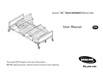
Bariatric Full-Electric Homecare Bed Model B600 User Manual READ THIS MANUAL BEFORE ASSEMBLING OR OPERATING THE BARIATRIC HOMECARE BED SAVE THIS MANUAL FOR FUTURE USE GF0500006RevD07 Contents Introduction...........................................................................................................................3 Warning / caution summary..............................................................................................3 Service..................................................................................................................................4 Radio Frequency Interference..................................................................................4 Handling....................................................................................................................................5 GF Health Products, Inc. Freight Policy................................................................5 Unpacking............................................................................................................................5 Inspection...........................................................................................................................5 Storage................................................................................................................................5 ASSEMBLY INSTRUCTIONS........................................................................................................6 Assemble Bed Head and Foot Sections...................................................................6 Install Casters.................................................................................................................9 Assemble and Install Drive Shaft...........................................................................11 Check Electrical Connections...............................................................................13 BED OPERATION........................................................................................................................14 Pendant Hand Control—Operate Bed Functions.............................................14 Trendelenberg Position.............................................................................................15 Reverse Trendelenberg Position...........................................................................15 Assemble and Install Head Rails (Optional).............................................................16 MAINTENANCE AND SAFETY CHECKS...................................................................................17 Check Electronics........................................................................................................17 Check Bed Frame and Sleeping Surface...............................................................17 Check Bed Ends (Head and Foot)..............................................................................17 Check Drive Shaft..........................................................................................................18 Check Casters.................................................................................................................18 Lubrication and Mechanical.....................................................................................18 Cleaning.............................................................................................................................18 SPECIFICATIONS........................................................................................................................19 Electrical.........................................................................................................................19 Shipping Weight (Bed Only)..........................................................................................19 Weight Capacity..............................................................................................................19 Construction..................................................................................................................19 Finish....................................................................................................................................19 Deck Height, High Position..........................................................................................20 Deck Height, Low Position..........................................................................................20 Bed Length........................................................................................................................20 Deck Width........................................................................................................................20 Service Parts.........................................................................................................................21 Head and Foot Service Motor Installation........................................................22 Warranty.................................................................................................................................23 GF0500006RevD07 Introduction All information and specifications in this manual are current at the time of printing. Please read this manual, including the following Warning / Caution Summary, in full before using your homecare bed. Always consult your professional healthcare advisors for their recommendations about safety, and never hesitate to ask for their assistance. Please heed the significance of the following special statements used throughout this manual: Note:Special helpful information set off from the text. CAUTION: Damage to equipment is possible. WARNING: Personal injury could occur. Warning / caution summary CAUTION: WARNING/CAUTION labels applied to the bed describe hazards or unsafe practices that could result in personal injury and/or property damage. Do not remove such labels. WARNING: Your Bariatric Homecare Bed, engineered to provide you with years of reliable operation, is for home use only. It is not intended for hospital use. WARNING: This device is equipped with a three-prong (grounding) plug for protection against possible shock hazard. Where a two-prong wall receptacle is encountered, it is the bed user’s responsibility and obligation to contact a qualified electrician to have the two-prong receptacle replaced with a properly grounded three-prong wall receptacle in accordance with the National Electrical Code. Do not modify the bed's plug in any way. WARNING: If an extension cord must be used, use a three-conductor cord with the same or higher electrical rating as bed cord, with ground, properly wired, in good electrical condition, and keep it as short as possible. WARNING: Do not use the bed if the cord or plug is damaged or defective. Use of a defective cord or plug could result in fire or electric shock. WARNING: Locate all bed cords so that they will not be stepped on, tripped over, or otherwise subjected to damage or stress. WARNING: Do not use explosive gases near bed. Possible fire hazard exists when used with oxygen-administering equipment other than nasal or masked type. WARNING: When using liquids in or around the bed, use caution to ensure that liquids of any kind are not spilled. If a liquid is spilled in or around the bed, unplug the bed immediately. Clean up spill and allow bed or area around bed to dry thoroughly before using the electric controls again. WARNING: Ensure that patient’s body weight is evenly distributed over the entire sleeping surface of the bed, and that the patient does not lie, sit, or lean in such a manner that the entire body weight is placed only on raised head or foot sections of the bed (this also applies to those providing assistance in repositioning or transferring the patient into or out of the bed). GF0500006RevD07 WARNING: Do not move or push the bed while it is in an elevated position; always lower the bed to its lowest position before moving. WARNING: Ensure that the casters are unlocked and free from restriction before moving the bed. WARNING: Keep hands and feet clear of all moving parts. WARNING: Never permit anyone under the bed at any time. WARNING: Do not leave the bed unattended when plugged in. WARNING: Do not allow small children on or near the bed during operation; do not allow small children to operate the bed. WARNING: When operating any of the bed’s movement functions, always ensure that the patient is positioned properly within the confines of the bed. Do not let any extremities protrude over the side or between the bed rails when performing any function. WARNING: The Bariatric Homecare Bed has been designed to accommodate a maximum patient weight of 600 lbs. under normal operating conditions. WARNING: Do not use with bed-mount trapeze or bed-mount traction devices. WARNING: Do not use bed as a patient transport. WARNING: Do not use unauthorized side rails, parts, accessories, or adapters other than those authorized by GF Health Products, Inc. CAUTION: The pendant hand control cord must be routed and secured properly to ensure that the cord does not become entangled and eventually severed during use. Ensure that electrical cords do not get tangled around the bed, side rails or legs during normal bed operation. CAUTION: When using nasal or masked-type administration equipment, oxygen or air tubing must be routed and secured properly to ensure that tubing does not become entangled and eventually severed during normal bed operation. CAUTION: Keep all moving parts free of obstructions (i.e. blankets, sheets, heating blankets/pads, tubing, wiring, and other objects). Service WARNING: The bed's electronic system contains no serviceable parts. Do not open the motors, pendant hand control, or junction box; only an authorized equipment provider or factory-trained personnel may perform service or adjustments on these components. Radio Frequency Interference WARNING: Most electronic equipment is influenced by Radio Frequency Interference (RFI). ALWAYS exercise caution with regard to the use of portable communications equipment in the area around such equipment. GF0500006RevD07 Handling GF Health Products, Inc. Freight Policy For Your Protection, Read Carefully The carrier accepted this merchandise “in good condition” and is responsible for safe delivery. Before signing the freight bill, inspect the shipment carefully for damage or missing pieces. Apparent Loss or Damage Should visual inspection show loss or damage, this MUST be noted on the freight bill and signed by the carrier’s agent. Failure to do so may result in the carrier failing to honor the claim. Please contact the carrier to obtain the paperwork necessary to file a claim. Concealed Loss or Damage If damage is discovered after delivery is made, a concealed damage claim must be entered with the freight carrier. When this occurs, make a written request to the carrier for inspection. This request for inspection must be made within 15 days of delivery. The carrier will provide all paperwork necessary to file a concealed damage or loss claim, since such damage or loss is the carrier’s responsibility. Unpacking Note:Unless the bed is to be used immediately, retain containers and packing materials for storage until bed use is required. 1. Check for obvious damage to the carton or its contents. If damage is evident, please notify the carrier and your Graham-Field equipment provider. 2. Remove all loose packing from the carton. 3. Carefully remove all the components from the carton. Inspection WARNING: Do not operate bed controls before assembling bed. 1. 2. 3. 4. Examine each item carefully for nicks, dents, scratches or other damages. Inspect all cords for cuts or damage to the cord and/or plug. Inspect the junction box for any damage to the connectors. Ensure that the motor plugs are in good working order and fit properly into the junction box. Storage Unless the bed is to be used immediately, retain containers and packing materials for storage until bed use is required. Store the repackaged bed in a dry area. DO NOT place anything on top of the repackaged bed. GF0500006RevD07 ASSEMBLY INSTRUCTIONS WARNING: Bed assembly requires two people because the bed is very heavy. Assemble Bed Head and Foot Sections 1. Lay the bed foot section on the floor, with head section close by, as shown below. Head Section Foot Section Assembly 1 2. Attach the head section to the foot section by inserting the head section rivets into the foot section hooks as shown below. Head Hook Rivet Foot Assembly 2 GF0500006RevD07 3. Rotate the head section down flat on the floor as shown in Assembly 3 below, taking care to keep the rivets and hooks engaged. WARNING: Before continuing, ensure that the head section rivets are properly seated in the foot section hooks; otherwise, personal injury and/or property damage may result. Lay out the trusses that were packed with the head section to prepare for installation. Locate shoulder bolts on each side of the frame for mounting each truss (two shoulder bolts on each side, as shown in Assembly 3 below). Shoulder Bolt Head Section Foot Section Truss Shoulder Bolt Assembly 3 4. Slide each end of truss over a shoulder bolt on outside of frame, as shown in Assembly 4 and Assembly 5 at right. Truss Shoulder Bolt Assembly 4 5. Secure the truss to the frame: Bolt the vertical truss link to the inside of the frame as shown in Assembly 6 at right, using the bolt that is loosely attached to the vertical truss link. Hold the truss firmly in place and use two 9/16" wrenches to tighten the bolt. GF0500006RevD07 Assembly 5 Truss Frame Loosely Attached Bolt Assembly 6 Vertical Truss Link 6. Repeat steps 4 and 5 for other side of bed. See Assembly 7 below to view the full bed frame with the trusses attached, and verify that you have installed them correctly. Head Motor Cord Power Cord / Pendant Hand Control Truss Assembly 7 7. See Assembly 7 above: Note orientation of head motor cord and power cord/pendant hand control. Cut the larger tie strap that holds the head motor cord; discard the tie strap. Remove the power cord and pendant hand control from the tie strap that holds them to the bed, being careful not to damage the tie strap as it is used later. 8. See Assembly 8 at right: Note Head Motor Cord orientation of head motor cord. Uncoil the head motor cord and route it along the frame, looping it through and around the tie strap as shown in Assembly 9. Assembly 8 9. Once the cord is routed properly, plug it into the junction box where marked for the head motor, as shown in Assembly 9 at right. Cut off the excess part of the tie strap and discard it. Tie Strap Plug Junction Box Cord Assembly 9 GF0500006RevD07 10.Turn the bed over carefully, so that the sleeping surface is facing up and the bed is resting on the motor guard tubes, to prepare for final assembly. 11.Remove the pin and washer, shown in Assembly 10 at right, from the rivet plates on both sides so that the bed ends can be attached. The pins and washers must be replaced after the bed ends are attached to the frame, to act as a safety latch. Pin and Washer – remove, to be replaced later Assembly 10 HEAD END Install Casters swivel caster locking caster locking caster swivel caster Note:Position the two locking casters where easily accessible, and at diagonally opposite corners of the bed, as shown at right. 1. Insert the square caster post directly into the bottom of the leg, centering the caster grip ring in the leg. 2. Tap the caster gently with a mallet or hammer, forcing the caster grip ring to compress and enter the leg. Continue until the square caster post is entirely inside the leg tube. 3. Repeat steps 1 and 2 for the other three casters. FOOT END Install Casters GF0500006RevD07 Assemble Bed Ends Foot Bed End Foot Section Frame Assemble Foot End 1 Rivet Corner Lock Corner Plate Assemble Foot End 2 Assemble Foot End 3 (Completed Assembly) 1. Standing directly in front of the foot end, position the footboard as close to the foot end as possible (see “Assemble Foot End 1”, above). 2. With one person on each side of the bed, reach over the bed end and lift up the bed. 3. Tilt the bed end slightly back toward you. 4. Engage lower rivet slightly and tilt end toward Pin and bed. Washer Bed End Hook 5. Lower bed into corner lock. 6. Repeat steps 1-4 for the head end section. 7. Replace pins and washers on both sides that were removed from the rivet plates during Assembly, step 11 (see Replace Pins and Washers at right). WARNING: Ensure that the pins and washers, which act as a safety latch, are replaced as shown. 10 Replace Pins and Washers GF0500006RevD07 Assemble and Install Drive Shaft The telescoping drive shaft consists of inner and outer shafts. The inner shaft has a positioning spring button; the outer shaft has several positioning holes. 1. Depress the spring button and insert inner shaft into outer shaft until desired hole, shown in Drive Shaft Assembly 1 below, is reached; engage the spring button into the spring button position hole as shown in Drive Shaft Assembly 2 below. Inner Shaft Spring Button Outer Shaft Spring Button Position (3rd Hole) Drive Shaft Assembly 1 Spring Button Drive Shaft Assembly 2 Attach Foot End First 1st 2nd Head End Gearbox Foot End Gearbox Drive Shaft Assembly 3 Note: Your bed may look different than bed shown above. 2. Connect the drive shaft to the bed by first attaching either end of the drive shaft to the foot end gear box. 3. Connect drive shaft’s other end to the head end gearbox. GF0500006RevD07 11 4. Release the spring-loaded coupler by gently rotating it clockwise until coupler engages with gearbox. Slide in and Rotate to Lock Coupler Gearbox Lock Coupler Rotate to Unlock Gearbox Coupler Unlock Coupler 12 GF0500006RevD07 Check Electrical Connections 1. Check all electrical connections to junction box; ensure that all motors are plugged into the appropriate connectors. Power Pendant Hand Control Foot Motor Hi/Lo Motor Head Motor Junction Box 2. Plug the junction box power cord into a properly grounded 110 volt, 60 cycle outlet. GF0500006RevD07 13 BED OPERATION Pendant Hand Control—Operate Bed Functions Lower Head Raise Head Lower Bed Raise Bed Lower Foot Raise Foot Pendant Hand Control The picture above details each pendant hand control button function. 1. To check connections and operation, press each button to operate all six bed functions: Lower head: Lowers only the head section of the bed. Raise head: Raises only the head section of the bed. Lower bed: Lowers the entire bed platform. Raise bed: Raises the entire bed platform. Lower foot: Lowers only the foot section of the bed. Raise foot: Raises only the foot section of the bed. 2. If any of the functions do not work as expected, recheck all electrical and mechanical connections, then recheck functions. Note: The bed has an emergency crank, which connects to the foot end, that allows continued operation in the event of a power outage. 14 GF0500006RevD07 Trendelenberg Position 1. Lower bed platform to its lowest height. Disengage the Hi/Lo drive shaft: Compress the spring fitting and remove the drive shaft from the motor. 2. Use the pendant hand control or crank to raise the foot bed end. The head end will remain in the low position. Reverse Trendelenberg Position 1. Raise bed platform to its highest height. Disengage the Hi/Lo drive shaft: Compress the spring fitting and remove the drive shaft from the motor. 2. Use the pendant hand control or crank to lower the foot bed end. The head end will remain in the high position. GF0500006RevD07 15 Assemble and Install Head Rails (Optional) Locate rails and hardware needed to attach the head section rails to the bed; the picture at right shows one of the two rails included in the box with the hardware needed to mount it. You will need: Two head rails Two large shoulder bolts Two wave washers Two large Nyloc nuts (for shoulder bolts) One 7/8" wrench (for shoulder bolts) One 3/4" wrench (for Nyloc nut) After both rails are attached you may discard the extra, unnecessary hardware and rail mounting brackets. 1. Elevate the head section at least 30° for ease of access. 2. Locate the head section rail mounting brackets (shown at right). When you mount your rails to the bed, you will use the set of two holes closest to the headboard of the bed, as noted in Rail Assembly 2 at right. 3. Insert the shoulder bolts through both rail bushings as shown in Rail Assembly 3 at right. 4. Install the wave washers on the ends of the bolts. 5. Mount the rail to the rail bracket: Insert the threaded ends of the shoulder bolts into the holes labeled for mounting the rail to the bed in Rail Assembly 2. 6. Secure the rail to the bracket: Attach the Nyloc nuts to the bolts and tighten. 7. Repeat steps 2-6 to mount the second rail to the other side of the bed. When your rails are installed on the bed, they should look like Rail Assembly 4 at right. Ensure that you mounted the rails in the correct holes on the brackets, tightened the shoulder bolts to secure the rail, and installed the wave washers between the rail bushings and the rail brackets. To activate the rails, press the triggers and rotate the rails up or down to your desired position. 16 Nyloc Nuts Rail Shoulder Bolts and Wave Washers Rail Assembly 1 Rail Mounting Holes Used (2 of the 4 are not used) Head Section Rail Mounting Bracket Rail Assembly 2 Shoulder Bolt Pivot Arm Wave Washer Rail Bushing Rail Assembly 3 Rail Assembly 4 GF0500006RevD07 MAINTENANCE AND SAFETY CHECKS Note: Perform the following checks once per year or between patient placements. Check Electronics • Use pendant hand control to ensure that all functions work properly, and that each button performs the appropriate function: • Lower head: Lowers only the head section of the bed • Raise head: Raises only the head section of the bed • Lower bed: Lowers the entire bed platform • Raise bed: Raises the entire bed platform • Lower foot: Lowers only the foot section of the bed • Raise foot: Raises only the foot section of the bed • Check all cables for damaged or frayed wires: • Power cord • Foot actuator wire • Head actuator wire • Hi/Lo actuator wire • Pendant hand control cord • Ensure that all wires are routed and attached properly so they do not interfere with any moving parts. • Ensure that all plugs are fully inserted or attached. • Junction box: Ensure that all attaching hardware is securely tightened. Check Bed Frame and Sleeping Surface • Visually check all welds (ensure that there are no stress cracks): • Head section • Foot section • Main frame • Check joints between sleeping surface sections for loose fasteners. • Inspect center mounting rivets and latches to ensure that they are not sheared off or bent. • Inspect head and foot surfaces for bends, warping, or stress damage. Check Bed Ends (Head and Foot) • Inspect end panels and trim for holes and/or sharp edges. • Inspect corner locks for wear, cracks, or stress damage. GF0500006RevD07 17 Check Drive Shaft • Ensure that the spring button functions properly and locks both halves of the drive shaft. • Inspect the connections on both ends of the drive shaft for wear or bends. • Inspect the entire drive shaft for bends or stress damage. Check Casters • Ensure that the locking casters are positioned diagonally. • Check locks on both locking casters to ensure that they are functional. • Check casters to ensure that they roll properly. Lubrication and Mechanical • Lightly grease all actuator screw threads with white lithium grease. • Check all bolts and tighten as needed. Cleaning • The metal parts of the bed are covered with a baked epoxy coating. Clean all coated parts with mild detergent and warm water. Raise head and foot sections of the bed and remove dust from frame. Remove mattress and clean the mattress deck with mild detergent and warm water. Note:If you experience a problem with your homecare bed and are unable to resolve it yourself, please contact your Graham-Field equipment provider. WARNING: Unauthorized modification could change the structure of the bed, void the warranty, and create a hazardous condition, which could result in serious personal injury. 18 GF0500006RevD07 SPECIFICATIONS Electrical • UL 73 and CAN/CSA C22.2 No. 68-92 approved • Full-electric three-function operation • Motors: 1/10 Hp, 115 V / 60Hz, 1.6 amps Shipping Weight (Bed Only) • 306 lbs. Weight Capacity • Normal operating conditions: 700 lbs., evenly distributed including mattress, accessories, rails, etc. • Maximum patient weight: 600 lbs. Construction • • • • • • • • Frame: .1875 steel angle Sleeping Surface: 11 ga (.120) cold rolled steel Self-wrenching nut assembled for easy part replacement Split frame with removable ends for easy transport Truss-reinforced frame Ball screw bed ends Heavy-duty grid style sleeping surface Optional swing-down style trigger rail Finish • 5-stage bath: 1. S21F acid bath (cleans grease and oil from metal) 2. Fresh water rinse 3. QuiliPhos 20 phosphate coat (inhibits rust and helps maintain electrical charge during powder application) 4. Fresh water rinse 5. QuiliRinse 404 (seals metal for powder coating) • All parts are then coated with a colored epoxy powder and baked for 35 minutes at 375°F. The powder coating, which is to be approximately 2.5 mils thick, shall be a smooth, uniform finish without runs, wrinkles, or grit. GF0500006RevD07 19 Deck Height, High Position 27.0 in. Deck Height, Low Position 17.0 in. Bed Length 88.0 in. Deck Width 42.0 in. 20 GF0500006RevD07 Service Parts 12 12a 13 15 5a 14a 14b 5b 10 14a 14c Foot 3 3a Head 4 16 11 2 13 7 7a 1a 1b 1c 17 9 8 6 Item Part Number Description 1a * 100-6350-060 Caster, locking, square post 1b * 100-6350-061 Caster, non-locking (swivel), square post 1a ** 100-6350-050 Caster, locking, 7/16" round stem 1b ** 100-6350-051 Caster, non-locking (swivel), 7/16" round stem 1c ** 100-6350-052 Caster socket for round stem casters 2 554-2001-920 Emergency crank 3 650-2001-015-4 Medium oak cover panel, set of four panels 3a 650-2001-015 Medium oak cover panel, one each 4 600-1000-112 Pendant hand control 5a 554-3001-110 Junction box, no power cord 5b 554-3001-115 Power cord 6 554-2018-901 Hi/Lo rod assembly 7 650-2001-912 Head motor and actuator 7a 650-2001-004 Head motor extension cord 8 650-2001-913 Foot motor assembly 9 650-2001-914 Hi/Lo motor assembly 10 600-2001-910 Elbow, head 11 600-2001-912 Elbow, foot 12 650-2001-058-2 End capping, set of two 12a 650-2001-058 End capping, one each 13 650-2001-915 Truss assembly 14a 650-5002-000 Bed end set, head and foot 14b 650-5002-000H Bed end set, head only 14c 650-5002-000E Bed end set, foot only 15 650-5100-901 Head section, complete with motor 16 650-5104-902 Foot section, complete with motors 17 650-1000-000 Bed end locking hardware, set of four * Square metal post casters can be used on all bed ends by removing the plastic socket from the leg and inserting the caster directly into the leg tube. **Bed ends with serial numbers lower than 65002062000 are equipped with round stem casters and plastic leg sockets. Bed ends with serial numbers greater than 65002062000 are equipped with square metal post casters that do not use the plastic leg sockets. GF0500006RevD07 21 Note:To order replacement parts, please contact your Graham-Field equipment provider. WARNING: The use of non-Lumex replacement parts could change the structure of the bed, void the warranty, and create a hazardous condition, which could result in serious personal injury. Head and Foot Service Motor Installation The head and foot motors are equipped with limit switches that shut the motor off at the maximum height elevation, as well as in the down or level position. The limit switches are internal and limit the rotation of the motor's threaded rod. The limit switches are independent of the torque tube placement on the threaded rod. When the motor tube is not attached to the bed, the torque tube can be turned or rotated up and down the threaded motor rod and not affect the limit switch. When replacing either the head or foot motor, the square torque tube must be positioned correctly with the limit switch position to avoid motor or bed damage. Setting the Motor and Torque Tube 1. Attach motor with bracket to the bed frame. Do not attach the torque tube to the bed linkage yet. 2. With motor attached, and torque tube free, plug motor into proper receptacle of the junction box. 3. While holding the square motor tube, operate the down function of the pendant hand control. If the motor does not work, the limit is already set for the down or level position. If the motor operates, continue holding the down button until the motor stops running. Now the motor is set in the down or level position. 4. Ensure that the head or foot section is in the down/level position. At this time the tube can be rotated up or down to align the torque tube slot with the linkage hole. Do not operate or crank the motor; any threaded rod rotation will unset the limit. 5. Align the tube slot with the linkage hole and attach the tube with the clevis and ring pin. The tube should be free from pressure in the down position. The diagram below gives the approximate dimensions of a motor and tube set in the down position with the bed level. 6. Operate the bed control to elevate the head or foot until the upper limit switch stops the motor. The head maximum elevation is 55 degrees; the foot maximum elevation is 30 degrees. Run the motor back down to the level position, ensuring that the motor stops when the frame is level. Approximate distance from motor with motor limit down and bed level "A" dimension, head motor:10 inches "A" dimension, foot motor: 8 inches “A” ± .50 22 GF0500006RevD07 Warranty GF Health Products, Inc. warrants the Lumex Bariatric Full-Electric Homecare Bed as follows: • Two year warranty for defects in workmanship and materials of mechanical components, frame, and electronics. • During the warranty period, defective items will be repaired or replaced at manufacturer’s option at no charge. GF0500006RevD07 23 USA, Corporate Headquarters: Graham-Field Health Products 2935 Northeast Parkway Atlanta, Georgia, USA 30360 telephone: 800-347-5678, 770-447-1609 fax: 800-726-0601, 678-291-3232 Printed in China www.grahamfield.com GF, Graham-Field, and Lumex are registered trademarks of GF Health Products, Inc. Packaging, warranties and products are subject to change without notice. GF Health Products, Inc. is not responsible for typographical errors. © 2007 GF Health Products, Inc. GF0500006RevD07