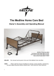
Download (Ver A) Universal Homecare Bed Manual (Ver A)
Transcript
Homecare Bed
Models:
SD0100N
SD0105A
SD0105N
SD0204A
SD0204N
User Manual
G0500007REVC07
WARNING / CAUTION SUMMARY
WARNING: KEEP HANDS AND FEET CLEAR OF ALL MOVING PARTS.
WARNING: DO NOT ALLOW SMALL CHILDREN ON OR NEAR BED DURING OPERATION.
WARNING: DO NOT ALLOW THIS DEVICE TO BE OPERATED BY SMALL CHILDREN.
WARNING: WHEN OPERATING THE HI-LO, KNEE, OR BACK FUNCTION OF THE BED, ALWAYS ENSURE
THAT THE INDIVIDUAL CONFINED TO THE BED IS POSITIONED PROPERLY WITHIN THE
CONFINES OF THE BED. DO NOT LET ANY EXTREMITIES PROTRUDE OVER THE SIDE OR
BETWEEN THE BED RAILS WHEN PERFORMING ANY FUNCTIONS.
CAUTION: DO NOT USE UNAUTHORIZED SIDE RAILS.
CAUTION: WARNING/CAUTION LABELS APPLIED TO THE BED OUTLINE HAZARDS OR UNSAFE
PRACTICES THAT COULD RESULT IN PERSONAL INJURY AND/OR PROPERTY DAMAGE.
CAUTION: PENDANT CORD MUST BE ROUTED AND SECURED PROPERLY TO ENSURE THAT CORD
DOES NOT BECOME ENTANGLED AND EVENTUALLY SEVERED DURING USE. MAKE
SURE ELECTRIC CORDS DO NOT GET TANGLED AROUND THE BED, SIDE RAILS OR LEGS
DURING NORMAL OPERATION OF THE BED.
CAUTION: WHEN USING NASAL OR MASKED TYPE ADMINISTERING EQUIPMENT, OXYGEN OR AIR
TUBING MUST BE ROUTED AND SECURED PROPERLY TO ENSURE THAT TUBING DOES
NOT BECOME ENTANGLED AND EVENTUALLY SEVERED DURING NORMAL OPERATION
OF BED.
CAUTION: BEFORE OPERATING, INSURE THAT THE BED FRAME RIVETS ARE PROPERLY SEATED IN
THE BED END HOOKS:OTHERWISE INJURY OR DAMAGE MAY RESULT.
CAUTION: KEEP ALL MOVING PARTS FREE OF OBSTRUCTIONS (I.E. BLANKETS/SHEETS, HEATING
BLANKETS/PADS, TUBING, WIRING, AND OTHER TYPES OF PRODUCTS)
G0500007REVC07
1
ASSEMBLY INSTRUCTIONS
FOR HOMECARE BED
FOOT
SECTION
Figure 1
HOOK
RIVET
HEAD
SECTION
NOTE: spring fabric not shown for clarity
•
•
Lay the head and foot section on their sides approximately 90o to each other (See
Figure 1).
Slide the sections together until the hook on the foot section catches the rivet on the
head section.
G0500007REVC07
2
ASSEMBLY INSTRUCTIONS (CONT.)
Figure 2
•
•
Straighten sections and position as shown in figure 2.
Position head wing as shown.
SPRING CLIPS
HEAD
FABRIC
FOOT
FABRIC
HEAD
WING
•
Figure3
Attach fabric halves-together using spring clips, which are attached to the foot fabric.
(See Figure 3)
G0500007REVC07
3
ASSEMBLY INSTRUCTIONS (CONT.)
HEAD TUBE
LANYARD/PIN
ASSEMBLY
EXTENSION TUBE
Figure4
Note: Insert clevis pin thru extension tube and into pivot lever.
Install washer and attach cotter pin. (See Fig. 4).
G0500007REVC07
4
ASSEMBLY INSTRUCTIONS (CONT.)
CASTER ASSEMBLY
HEAD END
SWIVEL
LOCKING
Figure5
FOOT END
•
Insert casters in bed ends by lining up caster shaft with hole in bottom of bed end
legs, and gently pressing in until secured. The two locking casters should be placed
where accessible, preferably at opposite corners of the bed. (See Figure 5)
G0500007REVC07
5
ASSEMBLY INSTRUCTIONS
BED END ASSEMBLY
BED END
(FOOT)
FOOT SPRING
FRAME
FIGURE 6
RIVET
CORNER
LOCK
FIGURE 7
•
•
•
•
•
•
•
FIGURE 8 (COMPLETED ASSEMBLY)
On full electric models; first compress and secure motor extension before assembly.
Standing directly in front of the bed end, position it as close to the bed as possible.
With one hand reach over end and lift up bed.
Tilt the bed end slightly back toward you.
Engage lower rivet slightly and tilt end toward bed.
Lower bed into corner lock.
Repeat for head end.
G0500007REVC07
6
ASSEMBLY INSTRUCTIONS (CONT.)
DRIVE SHAFT ASSEMBLY
•
•
The drive shaft is comprised of two sections – inner and outer tubes.
Depress spring button and insert until desired hole is reached (determined by which
bed, manual or electric hi/lo)
Inner Tube
Spring Button
FULL
ELECTRIC
MANUAL & SEMI
ELECTRIC
FIGURE 9
G0500007REVC07
Outer Tube
7
ASSEMBLY INSTRUCTIONS (CONT.)
DRIVE SHAFT ASSEMBLY
2nd
1ST
FOOT END
GEARBOX
ATTACH FOOT
END FIRST
HEAD END
GEARBOX
SPRING BUTTON
DRIVE SHAFT ASSEMBLY
•
Connect the drive shaft assembly to the bed by first attaching either side of drive shaft
to the foot end gearbox. Then attach other end to head end gearbox.
G0500007REVC07
8
ASSEMBLY INSTRUCTIONS (CONT.)
FULL ELECTRIC HI/LO
SLIDE IN AND
ROTATE TO
LOCK
COUPLER
LOCKING COUPLER
GEARBOX
ROTATE TO UNLOCK
COUPLER
UNLOCKING COUPLER
•
GEARBOX
On electric hi/lo model beds only – Release the spring-loaded coupler by gently
rotating it clockwise until coupler engages with gearbox.
G0500007REVC07
9
BED OPERATION
PENDANT
(Shown for Models SD0100A, SD0105A, & SD0204A)
Lower Head
•
•
•
Raise Head
Lower Bed
Raise Bed
Lower Foot
Raise Foot
Check all J-box connections and plug power cord into a properly grounded outlet
(110volt, 60 Hz).
In the event of a power failure, the emergency crank provided can be used to adjust
the head, hi-lo, and foot sections of the bed.
NOTE: Semi-Electric pendant does not have bed height adjustment (hi/lo) functions.
G0500007REVC07
10
BED OPERATION (CONT.)
JUNCTION BOXES
(Shown for Models SD0100A, SD0105A, & SD0204A)
FULL ELECTRIC – JUNCTION BOX
SEMI ELECTRIC – JUNCTION BOX
G0500007REVC07
11
BED OPERATION (CONT.)
MANUAL CRANK
RAISE
BED CRANK
HEAD CRANK
FOOT CRANK
LOWER
•
•
•
To raise bed – Turn the center crank
handle clockwise.
To raise headspring section – Turn the
left-hand crank handle clockwise.
To raise foot spring section – Turn the
right hand crank handle clockwise.
G0500007REVC07
•
•
•
12
To lower bed – Turn the center crank
handle counter-clockwise.
To lower head spring section – Turn
the left-hand crank handle counterclockwise.
To lower foot spring section – Turn
the right hand crank handle counterclockwise.
BED OPERATION (CONT.)
MANUAL CRANK (cont.)
Note: After unpacking bed, remove handles from sleeping surface
and attach as shown below.
CLEVIS PIN
STORAGE POSITION
OPERATING POSITION
HANDLE POSITION (STORAGE AND OPERATING)
OPERATION
•
Remove clevis pin and move handle to operating position: then reinsert clevis. The
crank is now ready to operate.
•
To store bed, reverse instructions above.
G0500007REVC07
13
BED OPERATION (CONT.)
TRENDELENBERG POSITION
•
Lower bed to its lowest height. Disengage the hi/lo drive shaft by compressing the
spring fitting and removing the drive shaft from the motor or bed end.
•
Raise the foot bed end using the hand pendant or crank. The head end will remain in
the low position.
REVERSE TRENDELENBERG
•
Raise bed to its highest height. Disengage the hi/lo drive shaft by compressing the
spring fitting and removing the drive shaft from the motor or bed end.
•
Lower the foot bed end using the hand pendant or crank. The head end will remain in
the high position.
G0500007REVC07
14
SPECIFICATIONS
DECK HEIGHT
BED HEIGHT (HIGH POSITION)
24.000
24.000
88.000
15.000
BED HEIGHT (LOW POSITION)/LENGTH
DECK WIDTH
36.000
G0500007REVC07
15
SPECIFICATIONS (CONT.)
ELECTRICAL
•
•
UL 73, CSA approved
MOTORS
• 1/10 Hp, 115Vlts/60Hz , 1.6 amps
WEIGHT
•
Normal operating conditions: 450 lbs. evenly distributed.
CONSTRUCTION
•
•
Frame: 10ga (.135) high strength, low alloy steel. (Roll formed)
Sleeping surface: 11ga (.120) cold rolled steel
FINISH
•
•
G0500007REVC07
5 stage bath
• 1) S21F acid bath (cleans grease and oil from metal).
• 2) Fresh water rinse.
• 3) QuiliPhos 20 phosphate coat (inhibits rust and helps maintain electrical
charge during powder application).
• 4) Fresh water rinse.
• 5) QuiliRinse 404 (seals metal for powder coating).
All parts are then coated with a colored epoxy powder and baked 35 minutes
at 375 degrees. The powder coating finish is to be approximately
2.5 mils thick. The coating will be a smooth, uniform finish without runs,
wrinkles, or grit.
16
Universal Bed
Replacement Parts
5
3a, 3b, 4a, 4b
9
6
11a, 11b, 11c
10
Foot
2, 4a, 4b
8b
8a
1
Head
12
7
Item
1
2
3a
3b
4a
4b
5
6
7
8a
8b
9
10
11a
11b
11c
12
13
14a
14b
15
G0500007REVC07
13
Part Number
HCB-CASTER
690-5001-000H
690-5001-000E
690-5001-000F
600-5001-000
690-5002-000
554-2001-015-4
554-2001-059-2
600-2001-910
600-2001-916
600-2001-912
554-2001-920
600-4100-901
600-4100-902
600-5105-902
600-5104-902
554-2018-901
600-1000-915
600-0666-918
600-0666-917
600-1000-903
14a, 14b
15
Description
Caster And Socket Set (4 EA)
Bed End, Head
Bed End, Foot, Full Elec
Bed End, Foot, Manual & Semi Elec
Hd & Ft Bed End Set, Man & Semi Elec
Hd & Ft Bed End Set, Full Elec
Bed End Panel, Walnut (4 Ea)
Bed End Capping, Brown (2 Ea)
Head Elbow
Foot Elbow, Manual, W/ Crank
Foot Elbow, Full Elec
Emergency Crank
Head Section Assy
Foot Section Assy, Manual
Foot Section Assy, Semi Elec
Foot Section Assy, Full Elec
Hi Lo Rod
Manual Extension Tube, Square
Screw & Tube Assem w/crank, Manual, Foot
Screw & Tube Assem w/crank, Manual, Head
Head/Foot Manual Crank
17
Universal Bed
Electronics Replacement Parts
Bed Models: SD0105A, SD0204A
Bed Models: SD0105N, SD0204N
16a
16b
18
17
19a
19b
20a
20b
25
21
26
23
22
Item
16a
16b
17
18
19a
19b
20a
20b
21
22
23
24
25
26
27
G0500007REVC07
Part Number
SD-CONT-SE
SD-CONT-FE
554-3001-115
999-0530-003
600-1000-111
600-1000-112
554-2001-111
554-2001-112
600-3001-914
600-1000-905
600-3001-912
600-3001-913
600-0666-914
600-0666-912
600-0666-913
24
22
27
Description
Control Box w/Power Cord, Semi Elec, Univ A
Control Box w/Power Cord, Full Elec, Univ A
Control Box Power Cord, Univ A
Control Box w/Power Cord, Full Elec, Univ N
Pendant, Semi Elec, Univ A
Pendant, Full Elec, Univ A
Pendant, Semi Elec Univ N
Pendant, Full Elec, Univ N
Hi/Lo Motor Assem, Univ A
Head Motor Extension Tube Assy
Head Motor Assem, Univ A
Foot Motor Assem, Univ A
Hi/Lo Motor Assem, Univ N
Head Motor Assem, Univ N
Foot Motor Assem, Univ N
18
MAINTENANCE AND SAFETY CHECKS
Once per year or between patient placements:
ELECTRONICS
• Check all controls to make sure all functions work properly.
• Foot control
• Head control
• Hi/Lo (if applicable)
• Check all cables for damaged or frayed wires.
• Power cord
• Foot actuator wire
• Head actuator wire
• Hi/Lo actuator wire
• Pendant cord
• Check to make sure all wires are routed and attached properly so they do not interfere
with any moving parts.
• Check to make sure all plugs are fully inserted or attached.
Bed frame and sleeping surface
• Visually check all welds
• Head section
• Knee section
• Main Frame
• Check joints between sleeping surface sections for loose fasteners.
Cleaning
• The metal parts of the bed are covered with a baked epoxy coating. Clean all coated
parts with mild detergent and warm water. Periodically raise head and feet sections
of the bed and remove dust from frame. Also, periodically remove mattress and clean
mattress deck.
Lubrication and Mechanical
• Lightly grease all actuator screw threads with white lithium grease.
• Lubricate all caster roller and swivel bearings with light machine oil.
• Check all bolts and tighten as needed.
WARRANTY
• Two year warranty for defects in workmanship and materials of mechanical components,
frame, and electronics.
• During the warranty period, defective items will be repaired or replaced at manufacturer's
option at no charge.
G0500007REVC07
19
U.S.A., Corporate Headquarters:
Graham-Field Health Products
2935 Northeast Parkway
Atlanta, Georgia 30360
telephone: 800-347-5678, 770-447-1609
fax: 800-726-0601, 678-291-3232
G0500007REVC07
http://www.grahamfield.com


