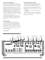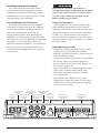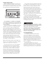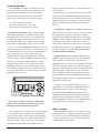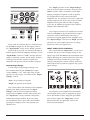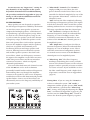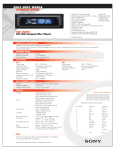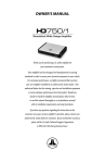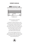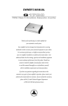
1
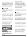
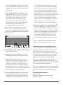
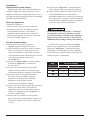
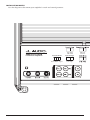
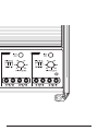
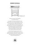
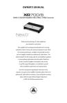
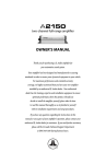
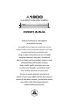
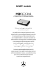
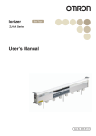
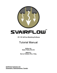
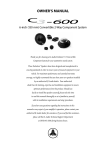
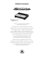
OWNER’S MANUAL 400W 2/3/4 Channel Amplifier Thank you for purchasing a JL Audio amplifier for your automotive sound system. Your amplifier has been designed and manufactured to exacting standards in order to ensure years of musical enjoyment in your vehicle. For maximum performance, we highly recommend that you have your new amplifier installed by an authorized JL Audio dealer. Your authorized dealer has the training, expertise and installation equipment to ensure optimum performance from this product. Should you decide to install the amplifier yourself, please take the time to read this manual thoroughly to familiarize yourself with its installation requirements and setup procedures. If you have any questions regarding the instructions in this manual or any aspect of your amplifier’s operation, please contact your authorized JL Audio dealer for assistance. If you need further assistance, please call the JL Audio Technical Support Department at (954) 443–1100 during business hours. PROTECT YOUR HEARING! We value you as a long-term customer. For that reason, we urge you to practice restraint in the operation of this product so as not to damage your hearing and that of others in your vehicle. Studies have shown that continuous exposure to high sound pressure levels can lead to permanent (irreparable) hearing loss. This and all other high-power amplifiers are capable of producing such high sound pressure levels when connected to a speaker system. Please limit your continuous exposure to high volume levels. While driving, operate your audio system in a manner that still allows you to hear necessary noises to operate your vehicle safely (horns, sirens, etc.). INSTALLATION APPLICATIONS This amplifier is designed for operation in vehicles with 12 volt, negative-ground electrical systems. Use of this product in vehicles with positive ground and/or voltages other than 12V may result in damage to the product and will void the warranty. This product is not certified or approved for use in aircraft. Do not attempt to “bridge” the outputs of this amplifier with the outputs of a second amplifier, including an identical one. SERIAL NUMBER In the event that your amplifier requires service or is ever stolen, you will need to have a record of the product’s serial number. Please take the time to enter that number in the space provided below. The serial number can be found on the bottom panel of the amplifier and on the amplifier packaging. Serial Number: Input Remote Mode Level Mode Input Switch Switch Voltage (pg. 7) (pg. 9) (pg. 7) Pre-Out Signal Turn-On Selection Switch Mode (pg. 9) (pg. 6) Preouts From 4 Channel Amplifier Status LED (pg. 11) Remote Level Mode 1&2 | Sum All | 3&4 Turn-On Mode Input Voltage Input Mode Rem. | Offset | Signal Low | High 2 Ch. | 4 Ch. 2 | JL Audio - XD400/4v2 Owner’s Manual Ch. 1 & 2 Filter Ch. 3 & 4 Ch. 3 & 4 Filter Ch. 1 & 2 Frequency Filter Mode Frequency Filter Mode Selector Selector Selection Selection (pg. 8) (pg. 8) (pg. 8) (pg. 8) Ch. 1 & 2 Input Ch. 3 & 4 Input Sensitivity Control Sensitivity Control (pg. 7) (pg. 7) PLANNING YOUR INSTALLATION It is important that you take the time to read this manual and that you plan out your installation carefully. The following are some considerations that you must take into account when planning your installation. Cooling Efficiency Considerations: The outer shell of your JL Audio amplifier is designed to remove heat from the amplifier circuitry. For optimum cooling performance, this outer shell should be exposed to the largest possible volume of air. Enclosing the amplifier in a small, poorly ventilated chamber can lead to excessive heat build-up and degraded performance. If an installation calls for an enclosure around the amplifier, we recommend that this enclosure be ventilated with the aid of a fan. In normal applications, fan-cooling is not necessary. Mounting the amplifier upside down is strongly discouraged. If mounting the amplifier under a seat, make sure there is at least 1 inch (2.5 cm) of space above the amplifier’s outer shell to permit proper cooling. Safety Considerations: Your amplifier needs to be installed in a dry, well-ventilated environment and in a manner which does not interfere with your vehicle’s safety equipment (air bags, seat belt systems, ABS brake systems, etc.). You should also take the time to securely mount the amplifier so that it does not come loose in the event of a collision or a sudden jolt to the vehicle. Stupid Mistakes to Avoid • Check before drilling any holes in your vehicle to make sure that you will not be drilling through a gas tank, brake line, wiring harness or other vital vehicle system. • Do not run system wiring outside or underneath the vehicle. This is an extremely dangerous practice which can result in severe damage to your vehicle and person. • Protect all system wires from sharp metal edges and wear by carefully routing them, tying them down and using grommets and loom where appropriate. • Do not mount the amplifier in the engine compartment, under the vehicle, on the roof or in any other area that will expose the amplifier circuitry to the elements. Chassis Ground Channels 1 & 2 Left & Right Preamp Connector Preamp Input Jacks Output Jacks (pg. 5) (pg. 6) (pg. 9) Jack for Remote Level Channels 3 & 4 +12 V Power Remote Turn-On Control Knob Preamp Input Jacks Connector Connector (pg. 9) (pg. 6) (pg. 5) (pg. 6) Channels 1 & 2 Speaker Outputs (pg. 10) Channels 3 & 4 Speaker Outputs (pg. 10) 3 PRODUCT DESCRIPTION The JL Audio XD400/4v2 is a four-channel, full-range audio amplifier utilizing JL Audio NexD™ ultra-high speed switching technology to deliver outstanding fidelity and efficiency. The XD400/4v2 can be operated with a wide variety of source units and system configurations. TYPICAL INSTALLATION SEQUENCE The following represents the sequence for a typical amplifier installation, using an aftermarket source unit or OEM Interface processor (like the CleanSweep CL441dsp). Additional steps and different procedures may be required in some applications. If you have any questions, please contact your authorized JL Audio dealer for assistance. 1) Disconnect the negative battery post connection and secure the disconnected cable to prevent accidental reconnection during installation. This step is not optional. 2) Run 8 or 4 AWG power wire from the battery location to the amplifier mounting location, taking care to route it in such a way that it will not be damaged and will not interfere with vehicle operation. Use 4 AWG or larger power wire and a fused power distribution block if additional amplifiers are being installed with the XD400/4v2. 3) Connect the power wire to the positive battery post. Fuse the wire with an appropriate fuse block (and connectors) within 18 inches (45 cm) wire length of the positive battery post. This fuse is essential to protect the vehicle. Do not install the fuse until the power wire has been securely connected to the amplifier. 4) Run signal cables and remote turn-on wire from the source unit to the final amplifier mounting location. 5) Run speaker cables from the speaker systems to the amplifier mounting location. 4 | JL Audio - XD400/4v2 Owner’s Manual 6) Find a good, solid metal grounding point close to the amplifier and connect the negative power wire to it using appropriate hardware (use of the JL Audio ECS master ground lug, XB-MGLU is recommended). Use 8 AWG wire, no longer than 36 inches (90 cm) from the amplifier to the ground connection point. In some vehicles, it may be necessary to upgrade the battery ground wire. (See page 5 for important notice). 7) Securely mount the amplifier. 8) Connect the positive and negative power wires to the amplifier. A fuse near the amplifier is not necessary if the XD400/4v2 is the only device being run from the fused main power wire. If the fused main power wire is shared by the XD400/4v2 and other amplifiers or devices, fuse each amplifier/device within 12 inches (30 cm) of wire length, via a fused distribution block or multiple individual fuse blocks/on-board fuses. 9) Connect the remote turn-on wire to the amplifier or configure the “Turn-On Mode” switch for automatic turn-on. 10) Connect the input cables to the amplifier. 11) Connect the speaker cables to the amplifier. 12) Carefully review the amplifier’s control settings to make sure that they are set according to the needs of the system. 13)Install the power wire fuse (40A for a single XD400/4v2) and reconnect the negative battery post terminal. Install the fuse (40A) near the amplifier (if applicable). 14) Turn on the source unit at a low level to double-check that the amplifier is configured correctly. Resist the temptation to crank it up until you have verified the control settings. 15) Make necessary adjustments to the input sensitivity controls to obtain the right overall output and the desired balance in the system. See Appendix A (page 14) for the recommended input sensitivity setting method. 16) Enjoy the fruits of your labor with your favorite music. POWER CONNECTIONS Before installing the amplifier, disconnect the negative (ground) wire from the vehicle’s battery. This will prevent accidental damage to the system, the vehicle and your body during installation. The XD400/4v2’s “+12 VDC” and “Ground” connections are designed to accept 4 AWG power wire. 8 AWG is the minimum required wire size for this amplifier. If you are installing the XD400/4v2 with other amplifiers and wish to use a single main power wire, use 4 AWG, 2 AWG or 1/0 AWG main power wire (depending on the overall current demands of all the amplifiers in the system). This 4 AWG, 2 AWG or 1/0 AWG power wire should terminate into a fused distribution block mounted as close to the amplifiers as possible (within 12 inches / 30cm of wire length). The fused output of the distribution block will connect to the XD400/4v2 with 8 AWG power wire. JL Audio ECS fused distribution blocks are recommended (XD-FDBU–2 and XD-FDBU–4). Note: Smaller AWG numbers mean bigger wire and vice-versa (1/0 AWG is the largest, 2 AWG is smaller, then 4 AWG, then 8 AWG, etc.). To connect the power wires to the amplifier, first back out the set screw on the top of the terminal block, using the supplied 2.5 mm hex wrench. Strip 1/2 inch (12 mm) of insulation from the end of each wire and insert the bare wire into the terminal block, seating it firmly so that no bare wire is exposed. While holding the wire in place, tighten the set screw firmly, taking care not to strip the head of the screw. The ground connection should be made using 8 or 4 AWG wire and should be kept as short as possible, while accessing a solid piece of sheet metal in the vehicle. The surface of the sheet metal should be sanded at the contact point to create a clean, metal-to-metal connection between the chassis and the termination of the ground wire. For optimal grounding, we recommend the use of a JL Audio ECS master ground lug (XB-MGLU). Alternatively, a sheet metal screw or bolt can be used with a star washer. Any wires run through metal barriers (such as firewalls), must be protected with a high quality rubber grommet to prevent damage to the insulation of the wire. Failure to do so may result in a dangerous short circuit. Many vehicles employ small (10 AWG - 6 AWG) wire to ground the battery to the vehicle chassis and to connect the alternator’s positive connection to the battery. To prevent voltage drops, these wires should be upgraded to 4 AWG when installing amplifier systems with main fuse ratings above 60A. FUSE REQUIREMENTS It is absolutely vital that the main power wire(s) to the amplifier(s) in the system be fused within 18 inches (45 cm) of the positive battery post connection. The fuse value at each power wire should be high enough for all of the equipment being run from that power wire. If only the XD400/4v2 is being run from that power wire, use a 40A fuse. If fusing the amplifier near its power connections (when more than one amp is being run from the main power wire), use a 40A fuse (MAXI™ big plastic-body fuse is recommended). 5 TURN-ON OPTIONS The XD400/4v2 can be switched on and off using one of three methods, determined by the position of the amplifier’s “Turn-On Mode” switch. Please read these options and decide which is best suited for your specific system. 1) +12V remote turn-on lead 2) Signal-sensing turn-on circuit. 3) DC offset-sensing turn-on circuit +12 V Remote Turn-On: This is the preferred method for turning the amplifier on/off. The amplifier will turn on when +12 V is present at its “Remote” input and turn off when +12 V is switched off. This +12 V remote turn-on signal is typically controlled by a source unit’s remote turn-on wire. The XD400/4v2’s “Remote” turn-on connector will accept 18 AWG – 12 AWG wire. To connect the remote turn-on wire to the amplifier, first back out the set screw on the top of the terminal block, using the supplied 2.5 mm hex wrench. Strip 1/2 inch (12mm) of wire and insert the bare wire into the terminal block, seating it firmly so that no bare wire is exposed. While holding the wire in the terminal, tighten the set screw firmly, taking care not to strip the head of the screw and making sure that the wire is firmly gripped by the set screw. If a source unit does not have a dedicated remote turn-on output, consider one of the following alternative turn-on options: These methods are useful when a conventional +12 V remote turn-on signal is not available in a system. These allow you to operate the amplifier without having to locate a remote turn-on lead at the source unit, which can be very useful when interfacing the amplifier with OEM (factory) 6 | JL Audio - XD400/4v2 Owner’s Manual audio systems that do not use conventional +12 V turn-on leads. Depending on the characteristics of the audio signal, one of the following methods may work better than the other. We recommend trying DC Offset-Sensing first as it does not require a long delay to turn the system off after the signal is shut off. DC Offset-Sensing: The amplifier will turn on and off by detecting the presence of a very small DC signal (offset) that is typical in the audio output of most OEM (factory) source units and amplifiers. The amplifier will turn on and off in reaction to the presence or absence of this DC Offset. The sensitivity of this circuit is designed for high-level (speaker level) signals, not for lowlevel (preamp level) signals. The circuit senses the left-channel signal only. Signal-Sensing: The amplifier will turn on and off by detecting the presence of a full-range audio signal at its left-channel input. After approximately 30 seconds, the amplifier will shut off. The sensitivity of this circuit is designed for high-level (speaker level) signals, not for low-level (preamp level) signals. The circuit is tuned to react to signals at mid-range frequencies. This prevents false switching from signals created by moving loudspeakers that are in parallel with the amplifier’s input signal. In signal sensing and DC offset sensing applications, the amplifier’s “Remote” turn-on terminal becomes a remote turn-on output. This allows the XD400/4v2 to turn on other amplifiers in the audio system that do not have signal sensing or DC offset sensing. Of course the XD400/4v2 must be the first amplifier in the signal path for this to function properly. INPUT SECTION The XD400/4v2’s input section allows you to send signals to the amplifier section through the use of two or four differential-balanced inputs. Input connections are via up to two pairs of traditional RCA-type jacks. el Amplifier The “High” position on the “Input Voltage” switch selects an input sensitivity range between 800mV and 8V. This is useful for certain highoutput preamp level signals as well as speaker level output from source units and small amplifiers. To use speaker level sources, splice the speaker output wires of the source unit or small amplifier onto a pair of RCA cables or plugs, or use the JL Audio ECS Speaker Wire to RCA adaptor (XD-CLRAIC2-SW). Preouts From Remote Level Mode 1&2 | Sum All | 3&4 Turn-On Mode Input Voltage Input Mode Rem. | Offset | Signal Low | High 2 Ch. | 4 Ch. If you wish to send four discrete channels into the XD400/4, simply use all four inputs and set the “Input Mode” switch in the “4 Ch.” position. If you wish to use only two channels of input to deliver signal to all four amplifier channels, set the “Input Mode” switch to “2 Ch.” and use only the inputs to channels 1 and 2. In this mode, channel 3 will operate with the channel 1 signal and channel 4 will operate with the channel 2 signal. Input Voltage Range: A wide range of signal input voltages can Preouts From Remote Level Mode be accommodated by the XD400/4v2’s input section (200mV – 8V). This wide range is split All | 3 &4 1&2 | Sum up into two sub-ranges, accessible via the “InputInput Mode Turn-On Mode Input Voltage 4 Channel Amplifier Voltage” switch: Rem. | Offset | Signal Low | High Line output converters are usually not needed with the XD400/4v2. If you find that the output cannot be reduced sufficiently with a direct speaker level signal applied to the amplifier and the “Input Voltage” switch in its “High” position, you may use a line output converter or voltage divider to reduce the signal level. INPUT SENSITIVITY CONTROLS The control labeled “Input Sens.” can be used to match the source unit’s output voltage to the input stage of the XD400/4v2 for maximum clean output. Rotating the control clockwise will result in higher sensitivity (louder for a given input voltage). Rotating the control counter-clockwise will result in lower sensitivity (quieter for a given input voltage). 2 Ch. | 4 Ch. “Low”: for preamp level signals “High”: for speaker level signals This switch affects all channels of the amplifier equally. The “Low” position on the “Input Voltage” switch selects an input sensitivity range between 200mV and 2V. This means that the “Input Sens.” rotary controls will operate within that voltage window. If you are using an aftermarket source unit, with conventional preamp level outputs, this is the position you should select. To properly set the amplifier for maximum clean output, please refer to Appendix A (page 14) in this manual. After using this procedure, you can then adjust the “Input Sens.” levels downward if this is required to achieve the desired system balance. 7 Do not increase any “Input Sens.” setting for any channel(s) of any amplifier in the system beyond the maximum level established during the procedure outlined in Appendix A (page 14). Doing so will result in audible distortion and possible speaker damage. FILTER CONTROLS Most speakers are not designed to reproduce the full range of frequencies audible by the human ear. For this reason, most speaker systems are comprised of multiple speakers, each dedicated to reproducing a specific frequency range. Filters are used to select which frequency range is sent to each section of a speaker system. The division of frequency ranges to different speakers can be done with passive filters (coils and/or capacitors between the amplifier outputs and the speakers), which are acceptable and commonly used for filtering between mid-range speakers and tweeters. Filtering between subwoofer systems and satellite speaker systems is best done with active filters, which cut off frequency content at the input to the amplifier. Active filters are more stable than passive filters and do not introduce extraneous resistance, which can degrade subwoofer performance. The active filter built into each channel section of the XD400/4v2 can be used to eliminate potentially harmful and/or undesired frequencies from making their way through the amplifier sections to the speaker(s). This serves to improve tonal balance and to avoid distortion and possible speaker failure. Correct use of these filters can substantially increase the longevity and fidelity of your audio system. Remote Level Mode All | 3 &4 Input Mode 2 Ch. | 4 Ch. 8 | JL Audio - XD400/4v2 Owner’s Manual 1) “Filter Mode” Controls: The XD400/4v2 employs 12dB per octave filters for each pair of channels. Each of these filters can be controlled or defeated completely by way of the three-position “Filter Mode” switches in each Channel Section: “Off”: Defeats the filter completely, allowing the full range of frequencies present at the inputs to feed these channels. This is useful for systems utilizing outboard active crossovers or requiring full-range reproduction from this channel pair. “LP” (Low-Pass): Configures the filter to attenuate frequencies above the indicated filter frequency, at a rate of 12dB per octave. This is useful for connection of subwoofers to one or more of the XD400/4v2’s channel pairs in a bi-amplified system. “HP” (High-Pass): Configures the filter to attenuate frequencies below the indicated filter frequency at a rate of 12dB per octave. This is useful for connection of component speakers or coaxials to one or more of the XD400/4v2’s channel pairs in a bi-amplified system. 2) “ Filter Freq. (Hz)” The filter frequency markings surrounding these rotary controls (one in each Channel Section) are for reference purposes and are generally accurate to within 1/3 octave or better. If you would like to select the filter cutoff frequency with a higher level of precision, consult the chart in Appendix B (page 15). Tuning Hint: If you are using the XD400/4v2 to drive a subwoofer system (“LP” mode), a component satellite speaker system (“HP” mode) or both, 80 Hz is a good baseline “Filter Freq. (Hz)” setting. After properly adjusting the “Input Sens.”, as outlined in Appendix A (page 14), you can fine tune the “Filter Freq. (Hz)” control to achieve the desired system frequency response. Amplifier REMOTE LEVEL CONTROL (OPTIONAL) With the addition of the optional Remote Level Control (HD-RLC), you can control the volume of one or both channel pairs of the XD400/4v2 from the front of the vehicle. This is useful for subwoofer level control, rear channel level control, center channel level control or even as a master volume control for the system. The HD-RLC connects to the jack labeled “Remote Level Control” on the Connection Panel of the amplifier using a standard telephone cable (supplied with the HD-RLC). If desired, multiple XD (and HD) amplifiers can be controlled from a single HD-RLC controller using a single-line, four-wire phone line splitter and multiple phone cables. When connected to the amplifier, the HD-RLC operates as follows: At full counter-clockwise rotation, the audio will mute completely. At full clockwise rotation the level will be the same as if the HD-RLC was not connected at all. In other words, it operates strictly as a level attenuator. Preouts From Remote Level Mode 1&2 | Sum All | 3 &4 Turn-On Mode Input Voltage Input Mode Rem. | Offset | Signal Low | High 2 Ch. | 4 Ch. “Remote Level Mode” Switch: This switch allows you to assign the operation of the HD-RLC to one or both pairs of channels. In the “All” position, the HD-RLC knob will affect all channels equally. In the “3&4” position, only the level of channels 3 and 4 will be affected by the HD-RLC knob (channels 1, and 2 will not). PREOUTS The XD400/4v2 incorporates a buffered, passthrough preamp output section, so that additional amplifiers can be easily added to the system. This pass-through preamp output can be configured two different ways using the switch labeled “Preouts From”. 1) “1&2”: the preamp output delivers the same signal that is connected to the “CH 1&2” inputs. This mode is useful for feeding a subwoofer amplifier when the XD400/4v2 is being used to drive front and rear speaker systems. In this mode, the preamp output signal will depend only on the input signal level of “CH 1&2”, allowing channels 3&4 to be faded without affecting the subwoofer level. If “CH 1&2” is faded in this mode, the signal level of the preamp output would change accordingly. 2) “Sum”: When the XD400/4v2 is being used to drive front and rear speaker systems, this preamp output mode will deliver a summed front/rear stereo signal to a subwoofer amplifier, while permitting fading of the front and rear speaker systems from the source unit. This method prevents a loss of signal to the subwoofer amplifier when the system is faded to the front or the rear by the head unit. Note: Any signal delay between the front and rear channels can result in a cancellation of signals within certain frequency ranges when using the “Sum” position. If you experience a loss of bass output in the “Sum” position, compared to the “1&2” position, you are likely dealing with a delayed signal in either the front or rear outputs of the source unit. If the front to rear delay is desirable for other reasons or if it cannot be defeated at the source unit, we recommend that you use the “1&2” position. Note: The preamp output delivers the same signal that is connected to the XD400/4v2’s inputs. The preamp output signal is not affected by the amplifier’s filter controls. If the input signal is full-range, the preamp output will be full-range. 9 Note: When the “Input Voltage” switch is in its “Low” position, the level of the “Preouts” signals matches the input signal levels (unity gain). When the “Input Level” switch is in the “high” position, the level of the input signal is attenuated –12 dB to produce a line level signal at the “Preouts”. This ensures a proper line level signal output under both conditions. If you plan to use the “Preouts” to feed a stereo amplifier, you must connect a stereo signal to the input of the amplifier. A mono signal into the amplifier will result in a mono signal out of the preamp output. SPEAKER OUTPUTS The XD400/4v2’s speaker outputs are designed to accept 16 AWG - 8 AWG wire. To connect the speaker wires to the amplifier, first back out the set screws on the top of the terminal block, using the supplied 2.5 mm hex wrench. Strip 1/2 inch (12 mm) of insulation from the end of each wire and insert the bare wire into the terminal block, seating it firmly so that no bare wire is exposed. While holding the wire in place, tighten the set screw firmly, taking care not to strip the head of the screw. Each pair of the XD400/4v2’s channels are designed to deliver power into speaker loads equal to or greater than 2 ohms when using a “stereo” configuration and speaker loads equal to or greater than 4 ohms when using a “bridged” configuration. Speaker loads below 2 ohms nominal per channel (or 4 ohms bridged) are not recommended and may cause the amplifier to initiate a protection mode which reduces power output. 10 | JL Audio - XD400/4v2 Owner’s Manual BRIDGING CONSIDERATIONS Bridging is the practice of combining the output of two amplifier channels to drive a single load. When bridged, each channel produces signals of equal magnitude, but opposite polarity. The combined output of the two channels provides twice the output voltage available from a single channel. The XD400/4v2 has been designed for bridging of its main channel pairs without the need for input inversion adaptors. To bridge a pair of main channels, use the “Left +” and “Right –”speaker connectors only (the “Left –” and “Right +” remain unused). Each bridged channel pair will deliver optimum power into a 4 ohm load. When a pair of the XD400/4v2’s channels are bridged, they will deliver 200W x 1 into a 4 ohm load or 150W x 1 into an 8 ohm load. Operating a pair of bridged channels into a load lower than 4 ohms is not recommended. A bridged pair of channels requires that both channels in the pair receive input. You must connect the mono or stereo source signal to both the left and right inputs of the bridged channel pair. Connection of only one input will result in reduced power output, increased distortion and can cause the amplifier to overheat. Do not do this! When a pair of the XD400/4v2’s channels are operating in bridged mode, the output will be in mono (only one channel). This mono channel can contain only right channel information, only left channel information, or the sum of the signals from right and left input channels. In order to achieve one of these options, configure the inputs to that pair of channels in one of these two ways: 1) L eft Channel Only or Right Channel Only Information: If you wish to send a left-only or right-only signal to a pair of the XD400/4v2’s channels you must use a “Y-Adaptor” to split the single channel signal into both left and right RCA inputs of the bridged channel pair. This option is used when deploying a pair of the XD400/4v2’s channels to drive left channel speakers only and the other pair of the XD400/4v2’s channels to drive right channel speakers only. 2) L eft + Right Channel Information: When bridged and fed by a stereo source signal, a bridged pair of the XD400/4v2’s channels will automatically combine the left and right input signals into a summed mono (left + right) input signal. This option is useful when using a pair of the XD400/4v2’s channels to drive a subwoofer system or a summed mono center channel. STATUS LED / PROTECTION CIRCUITRY There is a single multi-color LED on the top surface of the amplifier to indicate the amplifier’s operating status. Preouts From 4 Channel Amplifier very short in duration, it may manifest itself as an audible, repetitive ticking or thumping noise in the output. Over-current conditions can be caused by a speaker impedance lower than the optimum load impedance range for the amplifier or a short-circuit in the speaker wiring. The latter can result from a short circuit between the positive and negative speaker wires or between either speaker wire and the vehicle chassis. The “Status LED” will remain amber for a few seconds, even if the overcurrent condition is of a very short duration. 5) L ED off / Amplifier Shuts Off Unexpectedly The only condition that will shut down an undamaged XD400/4v2 completely is if battery voltage or remote turn-on voltage drops below 10 volts. The “Status LED” will turn off when this occurs. The amplifier will turn back on when voltage climbs back above 11 volts. If this is happening in your system, have your charging system and power wiring inspected. For more information on troubleshooting this amplifier, refer to Appendix D (pages 16, 17). Remote Level Mode 1&2 | Sum All | 3&4 Turn-On Mode Input Voltage Input Mode Rem. | Offset | Signal Low | High 2 Ch. | 4 Ch. 1) Flashing Green: The amplifier is powering up, audio output is muted. 2) C onstant Green: The amplifier is on and functioning normally, audio output is active. 3) C onstant Red: lights to indicate that the amplifier has exceeded its safe operating temperature, putting the amplifier into a self-protection mode, which reduces the peak power output of the amplifier. When its temperature returns to a safe level, the red light will return to green and the amplifier will return to full-power operating mode. 4) C onstant Amber (Yellow): Indicates that an over-current condition has occurred and is accompanied by a muting of the amplifier’s output. Because the muting behavior may be SERVICING YOUR JL AUDIO AMPLIFIER If your amplifier fails or malfunctions, please return it to your authorized JL Audio dealer so that it may be sent in to JL Audio for service. There are no user serviceable parts or fuses inside the amplifier. The unique nature of the circuitry in the JL Audio amplifiers requires specifically trained service personnel. Do not attempt to service the amplifier yourself or through unauthorized repair facilities. This will not only void the warranty, but may result in the creation of more problems within the amplifier. If you have any questions about the installation or setup of the amplifier not covered in this manual, please contact your dealer or technical support. JL Audio Technical Support: (954) 443-1100 9:00 AM – 5:30 PM (Eastern Time Zone) Monday - Friday 11 SYSTEM CONFIGURATIONS The XD400/4v2 is a flexible amplifier, wellsuited for a multitude of system configurations. In this section, the most likely configurations for a system with a single XD400/4v2 are explained in detail. Once you have selected your desired configuration, you can use the amplifier panel drawing on pages 18 & 19 to mark the required switch positions for easy reference. BI-AMPLIFIED SYSTEMS Bi-amplified systems are defined as systems in which separate amplifier channels drive lowfrequency (LF) and high-frequency (HF) speakers and are separately filtered to send appropriate frequency ranges to each speaker system. The most common application of bi-amplification in mobile audio is to drive a subwoofer system from one or more amplifiers or channels and component speakers from separate amplifiers or channels. The XD400/4v2 can be configured to drive a bi-amplified system by itself or with a separate subwoofer amplifier. Bi-Amplified System with one XD400/4v2 In this configuration, channels 3&4 of the XD400/4v2 will drive subwoofers (stereo or bridged) with low-pass filtering. Channels 1&2 will drive component speakers in stereo with high-pass filtering. Input connection options for a bi-amplified system with one XD400/4v2 are as follows: A) No User Adjustability: Required: a basic source unit or processor with one pair of stereo outputs. Input Connections: a single pair of stereo source unit outputs connected to the “CH 1 (Left)” and“CH 2 (Right)” inputs of the XD400/4v2 (select “2 Ch.” on the “Input Mode” switch). Result: the relative level of the LF and HF channels will be determined by the XD400/4v2’s “Input Sens.” settings and will not be user adjustable from the front of the vehicle. 12 | JL Audio - XD400/4v2 Owner’s Manual B) F ade Subwoofer Level vs. HF Level Required: a source unit or processor with two pairs of stereo outputs. Input Connections: the first stereo pair of source unit outputs is connected to the “CH 1 (Left)” and “CH 2 (Right)” inputs of the XD400/4v2. The second stereo pair of source unit outputs is connected to the “CH 3 (Left)” and “CH 4 (Right)” inputs (select “4 Ch.” on the “Input Mode” switch). Result: in this mode, the user has the ability to fade or control the level of the LF channels relative to the HF channels via the source unit’s fader control without exceeding the maximum clean output level set by each amplifier section’s “Input Sens.” controls. C) Subwoofer Level Control Only: Required: a source unit or processor with one pair of stereo outputs and dedicated subwoofer outputs. Input Connections: the main stereo pair of source unit outputs is connected to the “CH 1 (Left)” and “CH 2 (Right)” inputs of the XD400/4v2. The source unit’s dedicated subwoofer output is connected to the “CH 3 (Left)” and “CH 4 (Right)” inputs (select “4 Ch.” on the “Input Mode” switch). Result: in this mode, the user has the ability to control the absolute level of the LF channels relative to the HF channels. Set the “Input Sens.” in the “Channel 3 & 4 Controls” section with the source unit’s subwoofer level control set at 3/4 of full output. See Appendix A (page 14) for details. Crossover Setup for Bi-Amplified System with one XD400/4: Once the input sections have been configured appropriately, go to the “Channel 3 & 4 Controls”. Select “LP” (low-pass) on the “Filter Mode” switch and an appropriate “Filter Freq.” (80 Hz is a good starting point). Next, turn your attention to the “Channel 1 & 2 Controls” and select “HP” (high-pass) on the “Filter Mode” switch and an appropriate “Filter Freq.” (again, 80 Hz is a good starting point). After proper adjustment of the “Input Sens.” controls for both channel pairs using the method shown in Appendix A (page 14), you can fine tune filter frequencies and attenuate either pair of channels to achieve proper balance. For precise filter frequency information refer to Appendix B (page 15). MULTI-AMPLIFIER SYSTEMS Using the “Preamp Outputs” of the XD400/4v2, it is easy to configure many different multi-amplifier systems. The most common type involves the addition of a subwoofer amplifier, such as the XD600/1v2. Common configurations of such a system are described below. Bi-Amplified System with one XD400/4v2 in four-channel mode and a separate subwoofer amplifier This configuration requires that the separate subwoofer amplifier has a built-in low-pass filter. (All JL Audio amplifiers have this feature.) In this configuration, channels 1&2 of the XD400/4v2 will drive front component speakers in stereo with high-pass filtering. Channels 3&4 will drive rear component speakers in stereo, also with high-pass filtering. The separate amplifier will drive the subwoofer system with low-pass filtering (80 Hz is a good starting point). Here are three possible configuration options: A) Fade Subwoofer Level vs. HF Level: Required: a source unit or processor with front and rear pairs of stereo outputs. Input Connections: one stereo pair of source unit outputs is connected to the “CH 1 (Left)” and “CH 2 (Right)” inputs of the XD400/4v2 (select “2 Ch.” on the “Input Mode” switch). The second stereo pair of source unit outputs is connected to the subwoofer amplifier inputs. Result: with this option, the user has the ability to fade the level of the subwoofer amplifier’s input relative to the HF channels, but cannot control front-to-rear fading of the HF channels. The relative level of the front and rear HF channels will be fixed by the XD400/4v2’s “Input Sens.” settings and will not be user adjustable from the front of the vehicle. B) Subwoofer Level Control Only: Required: a source unit or processor with left, right and dedicated subwoofer outputs. Input Connections: The main stereo pair of source unit outputs is connected to the “CH 1 (Left)” and “CH 2 (Right)” inputs of the XD400/4v2 (select “2 Ch.” on the “Input Mode” switch). The source unit’s dedicated subwoofer output is connected to the subwoofer amplifier inputs. Result: with this option, the user has the ability to control the absolute level of the subwoofer channel relative to the HF channels, but cannot fade the front and rear HF channels relative to each other. Set the subwoofer amplifier’s “Input Sens.” with the source unit’s subwoofer level control set at 3/4 of full output. C) Front to Rear HF Fading and Subwoofer Level Control: Required: a source unit or processor with front and rear pairs of stereo outputs plus a dedicated subwoofer output. Input Connections: one stereo pair of source unit outputs is connected to the “CH 1 (Left)” and “CH 2 (Right)” inputs of the XD400/4v2. The second stereo pair of source unit outputs is connected to the “CH 3 (Left)” and “CH 4 (Right)” inputs of the XD400/4v2 (select “4 Ch.” on the “Input Mode” switch). The source unit’s dedicated subwoofer output is connected to the subwoofer amplifier inputs. 13 APPENDIX A: Input Sensitivity Level Setting Following the directions below will allow the installer to adjust the input sensitivity of each amplifier channel pair simply and easily in just a few minutes using equipment which is commonly available in installation bays. Necessary Equipment • Digital AC Voltmeter • CD with a sine-wave test tone recorded at 0 dB reference level in the frequency range to be amplified for that set of channels (50 Hz for subwoofer channels, 1 kHz for a midrange application). Do not use attenuated test tones (-10 dB, -20 dB, etc.). The Nine-Step Procedure 1) Disconnect the speaker(s) from the amplifier’s speaker output connectors. 2) Turn off all processing (bass/treble, loudness, EQ, etc.) on the source unit, processors (if used) and amplifier. Set the fader control to center position and the subwoofer level control to 3/4 of maximum (if used to feed the XD400/4v2). 3) Switch the “Input Voltage” switch to “Low” Turn both “Input Sens.” controls all the way down. 4) Set the source unit volume to 3/4 of full volume. This will allow for reasonable gain overlap with moderate clipping at full volume. 5) Using the chart on this page, determine the target voltage for input sensitivity adjustment according to the nominal impedance of the speaker system connected to the amplifier outputs. 6) Verify that you have disconnected the speakers before proceeding. Play a track with an appropriate sine wave (within the frequency range to be amplified by the XD400/4v2) at 3/4 source unit volume. 7) Connect the AC voltmeter to the speaker output connectors of the amplifier. Make sure you test the voltage at the correct connectors (+ and –). 14 | JL Audio - XD400/4v2 Owner’s Manual 8) Increase the “Input Sens.” control until the target voltage is observed with the voltmeter. 9) Once you have adjusted each channel section on the XD400/4v2 to its maximum lowdistortion output level, reconnect the speaker(s). The “Input Sens.” controls can now be adjusted downward if the amplifier requires attenuation to achieve the desired system balance. Do not increase any “Input Sens.” setting for any amplifier channel or channel pair in the system beyond the maximum level established during this procedure. Doing so will result in audible distortion and possible speaker damage. It will be necessary to re-adjust the “Input Sens.” if any equalizer boost is activated after setting the “Input Sens.” with this procedure. This applies to any EQ boost circuit, including source unit tone controls or EQ circuits. EQ cuts will not require re-adjustment. Nom. Impedance Target AC Voltage Stereo Bridged 8Ω 17.3 V 34.6 V 4Ω 17.4 V 28.2 V 2Ω 14.1 V not recommended APPENDIX B: Precise Frequency Selection Chart “FILTER FREQ” DetentPanelActual NumberMarking Freq. Full counter-clockwise: 49 01 . . . . . . . . . . . . . . . . . . . . . . . . . . . . 49 02 . . . . . . . . . . . . “50” . . . . . . . . . . . 49 03 . . . . . . . . . . . . . . . . . . . . . . . . . . . . 50 04 . . . . . . . . . . . . . . . . . . . . . . . . . . . . 50 05 . . . . . . . . . . . . . . . . . . . . . . . . . . . . 52 06 . . . . . . . . . . . . . . . . . . . . . . . . . . . . 53 07 . . . . . . . . . . . . . . . . . . . . . . . . . . . . 55 08 . . . . . . . . . . . . “60” . . . . . . . . . . . 57 09 . . . . . . . . . . . . . . . . . . . . . . . . . . . . 59 10 . . . . . . . . . . . . . . . . . . . . . . . . . . . . 61 11 . . . . . . . . . . . . . . . . . . . . . . . . . . . . 63 12 . . . . . . . . . . . . . . . . . . . . . . . . . . . . 65 13 . . . . . . . . . . . . . . . . . . . . . . . . . . . . 68 14 . . . . . . . . . . . . . . . . . . . . . . . . . . . . 70 15 . . . . . . . . . . . . . . . . . . . . . . . . . . . . 73 16 . . . . . . . . . . . . “80” . . . . . . . . . . . 76 17 . . . . . . . . . . . . . . . . . . . . . . . . . . . . 79 18 . . . . . . . . . . . . . . . . . . . . . . . . . . . . 83 19 . . . . . . . . . . . . . . . . . . . . . . . . . . . . 86 20 . . . . . . . . “12 o’clock” . . . . . . . 90 21 . . . . . . . . . . . . . . . . . . . . . . . . . . . . 95 22 . . . . . . . . . . . . . . . . . . . . . . . . . . . 100 23 . . . . . . . . . . . . . . . . . . . . . . . . . . . 105 24 . . . . . . . . . . . “120” . . . . . . . . . . 111 25 . . . . . . . . . . . . . . . . . . . . . . . . . . . 118 26 . . . . . . . . . . . . . . . . . . . . . . . . . . . 126 27 . . . . . . . . . . . . . . . . . . . . . . . . . . . 135 28 . . . . . . . . . . . . . . . . . . . . . . . . . . . 146 29 . . . . . . . . . . . . . . . . . . . . . . . . . . . 160 30 . . . . . . . . . . . . . . . . . . . . . . . . . . . 174 31 . . . . . . . . . . . . . . . . . . . . . . . . . . . 192 32 . . . . . . . . . . . “200” . . . . . . . . . . 217 33 . . . . . . . . . . . . . . . . . . . . . . . . . . . 243 34 . . . . . . . . . . . . . . . . . . . . . . . . . . . 286 35 . . . . . . . . . . . . . . . . . . . . . . . . . . . 339 36 . . . . . . . . . . . . . . . . . . . . . . . . . . . 406 37 . . . . . . . . . . . . . . . . . . . . . . . . . . . 444 38 . . . . . . . . . . . “500” . . . . . . . . . . 482 39 . . . . . . . . . . . . . . . . . . . . . . . . . . . 483 Full-clockwise: 483 APPENDIX C: XD400/4v2 Specifications General Specifications: Recommended Fuse Value: 40A Recommended Fuse Type: MAXI® or AGU Input Sections: No. of Inputs: Two Stereo Pairs Input Type: Differential-balanced with RCA jack inputs Input Range: 200mV - 8V RMS Amplifier Section: Amplifier Topology: NexD™ Ultra-High Speed Class D Power Supply: Unregulated MOSFET switching type Rated Power at 14.4V with less than 1% THD+Noise (20Hz - 20 kHz) RMS Method Stereo, all channels driven: 75W RMS x 4 @ 4 ohms, 100W RMS x 4 @ 2 ohms Bridged, all channels driven: 150W RMS x 2 @ 8 ohms, 200W RMS x 2 @ 4 ohms Rated Power @ 12.5V with less than 1% THD + Noise (20Hz - 20 kHz) RMS Method Stereo, all channels driven: 60W RMS x 4 @ 4 ohms, 90W RMS x 4 @ 2 ohms Rated Power Bridged, all channels driven: 120W RMS x 2 @ 8 ohms, 180W RMS x 2 @ 4 ohms Signal to Noise Ratio: >104 dB referred to rated power (A-weighted, 20 Hz-20 kHz noise bandwidth) >84 dB referred to 1W (A-weighted, 20 Hz-20 kHz noise bandwidth) Frequency Response: 12 Hz - 22 kHz (+0, -1dB) Damping Factor: >150 @ 4 ohms per ch./ 50 Hz >75 @ 2 ohms per ch. / 50 Hz Crossover Filters: Filter Type: State-variable, 12dB/octave Butterworth with continuously variable cutoff frequency selection from 50-500 Hz. Configurable as Low-Pass or High-Pass. Defeatable. Dimensions (LxWxH): 8.52" x 7.09" x 2.05" (217mm x 180mm x 52mm) Due to ongoing product development, all specifications are subject to change without notice. 15 APPENDIX D: TROUBLESHOOTING “How do I properly set the input sensitivity on my amplifier?” Please r efer to Appendix A (page 14) to set the input sensitivity for maximum, low-distortion output. “My amplifier doesn’t turn on.” Check t he fuse, not just visually, but with a continuity meter. It is possible for a fuse to have poor internal connections that cannot be found by visual inspection. It is best to take the fuse out of the holder for testing. If no problem is found with the fuse, inspect the fuse holder. Check t he integrity of the connections made to each of the “+12VDC,” “Ground,” and “Remote” terminals. Ensure that no wire insulation is pinched by the terminal set screw and that each connection is tight. Check t o make sure there is +12V at the “Remote” connection of the amplifier. In some cases, the turn-on lead from the source unit is insufficient to turn on multiple devices and the use of a relay is required. To test for this problem, jump the “+12VDC” wire to the “Remote” terminal to see if the amplifier turns on. “I get a repetitive ticking or popping sound coming out of the speaker(s).” Check t he speaker wires for a possible short, either between the positive and negative leads or between either speaker lead and the vehicle’s chassis ground. If a short is present, you will experience distorted and/or attenuated output. The “Status LED” will turn amber in this situation. It may be helpful to disconnect the speaker wires from the amplifier and use a different set of wires connected to a test speaker. Check t he nominal load impedance to verify that the amplifier is driving a load equal to or greater than 2 ohms. “My amplifier’s output fluctuates when I tap on it or hit a bump.” Check t he connections to the amplifier. Make sure that the insulation for all wires has been stripped back far enough to allow for a good contact area inside the terminal block. Check the input connectors to ensure that they all are making good contact with the input jacks on the amplifier. 16 | JL Audio - XD400/4v2 Owner’s Manual “My amplifier shuts off once in a while, usually at higher volumes.” Check y our voltage source and grounding point. The power supply of the XD400/4v2 will operate with charging system voltages down to 10V. Shutdown problems at higher volume levels can occur when the charging system voltage (or remote turn-on voltage) drops below 10V. These dips can be of very short duration making them extremely difficult to detect with a common DC voltmeter. To ensure proper voltage, inspect all wiring and termination points. It may also be necessary to upgrade the ground wire connecting the battery to the vehicle’s chassis and the power wire connecting the alternator to the battery. Many vehicles employ small (10 AWG - 6 AWG) wire to ground the battery to the vehicle’s chassis and to connect the alternator to the battery. To prevent voltage drops, these wires should be upgraded to 4 AWG when installing amplifier systems with main fuse ratings above 60A. Grounding problems are the leading cause of misdiagnosed amplifier “failures.” “My amplifier turns on, but there is no output.” Check the input signal using an AC voltmeter to measure the voltage from the source unit while an appropriate test tone is played through the source unit (disconnect the input cables from the amplifier prior to this test). The frequency used should be in the range that is to be amplified by the amplifier (example: 50 Hz for a sub bass application or 1 kHz for a full range / high-pass application). A steady, sufficient voltage (between 0.2 and 8.0-volts) should be present at the output of the signal cables. Check t he output of the amplifier. Using the procedure explained in the previous check item (after plugging the input cables back into the amplifier) test for output at the speaker outputs of the amplifier. Unless you enjoy test tones at high levels, it is a good idea to remove the speaker wires from the amplifier while doing this. Turn the volume up approximately halfway. 5 volt AC or more should be measured at the speaker outputs. This output level can vary greatly between amplifiers but it should not be in the millivolt range with the source unit at half volume. If you are reading sufficient voltage, check your speaker connections as explained below. Check to ensure that the speaker wires are making a good connection with the metal inside the terminal block. The speaker wire connectors are designed to accept up to 8 AWG wire. Make sure to strip the wire to allow for a sufficient connection with the metal inside the terminal block. 17 INSTALLATION NOTES: Use this diagram to document your amplifier’s switch and control positions. 4 Channel Amplifier 18 | JL Audio - XD400/4v2 Owner’s Manual Turn-On Mode Input Voltage Rem. | Offset | Signal Low | High 19 LIMITED WARRANTY - AMPLIFIERS (USA) JL AUDIO warrants this product to be free of defects in materials and workmanship for a period of two (2) years. The warranty is extended to three (3) years total if installation is performed by an authorized JL Audio dealer using a JL Audio Premium Power Connection System for power wiring. This warranty is not transferrable and applies only to the original purchaser from an authorized JL AUDIO dealer. Should service be necessary under this warranty for any reason due to manufacturing defect or malfunction, JL AUDIO will (at its discretion), repair or replace the defective product with new or remanufactured product at no charge. Damage caused by the following is not covered under warranty: accident, misuse, abuse, product modification or neglect, failure to follow installation instructions, unauthorized repair attempts, misrepresentations by the seller. This warranty does not cover incidental or consequential damages and does not cover the cost of removing or reinstalling the unit(s). Cosmetic damage due to accident or normal wear and tear is not covered under warranty. Warranty is void if the product’s serial number has been removed or defaced. Any applicable implied warranties are limited in duration to the period of the express warranty as provided herein beginning with the date of the original purchase at retail, and no warranties, whether express or implied, shall apply to this product thereafter. Some states do not allow limitations on implied warranties, therefore these exclusions may not apply to you. This warranty gives you specific legal rights, and you may also have other rights which vary from state to state. If you need service on your JL AUDIO product: All warranty returns should be sent to JL AUDIO ’s Amplifier Service Facility freight-prepaid through an authorized JL AUDIO dealer and must be accompanied by proof of purchase (a copy of the original sales receipt). Direct returns from consumers or non-authorized dealers will be refused unless specifically authorized by JL AUDIO with a valid return authorization number. Warranty expiration on products returned without proof of purchase will be determined from the manufacturing date code. Coverage may be invalidated as this date is previous to purchase date. Nondefective items received will be returned freight-collect. Customer is responsible for shipping charges and insurance in sending the product to JL AUDIO. Freight damage on returns is not covered under warranty. For Service Information in the U.S.A. please call JL Audio Customer Service: (954) 443-1100 9:00 AM – 5:30 PM (Eastern Time Zone) JL Audio, Inc 10369 North Commerce Pkwy. Miramar, FL 33025 (do not send product for repair to this address) International Warranties: Products purchased outside the United States of America are covered only by that country’s distributor and not by JL Audio, Inc. Printed in China XD400/4v2 MAN-09-2013