1
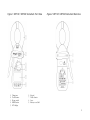
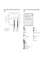
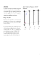
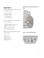
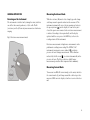
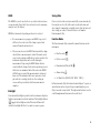
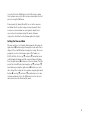
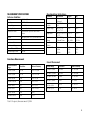
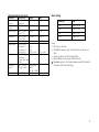
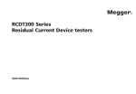
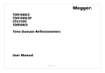
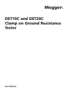
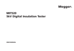
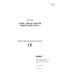
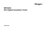
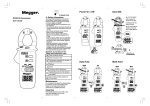
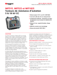
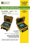
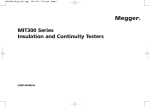
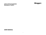
M DET14C and DET24C Digital Earth Clamp-on Tester USER GUIDE 1 G SAFETY WARNINGS These safety warnings are provided to ensure the safety of personnel and proper operation of the instrument. ■ Safety warnings and precautions must be read and understood before the instrument is used. They must be observed during use. ■ Do not leave the instrument connected to the system under test when not in use. ■ Do not touch circuit connections and exposed metalwork of the installation or equipment under test. ■ Do not use the instrument or connect it to any external system if it shows any visible signs of damage, malfunction or if it has been stored in unfavourable conditions. ■ Always keep body parts behind the tactile barrier on the handles of the instrument. ■ Always inspect the instrument prior to use. Replace any defective parts immediately or return the instrument to an authorised service centre for repair. ■ Do not use the instrument or connect it to any external system if the casing is open or any parts of the case are missing. ■ Do not use rechargeable batteries in this instrument. ■ Always use caution when clamping the instrument around energised electrical conductors. ■ Always use extreme caution when clamping around bare conductors: under fault conditions, high voltages and currents may be present and may pose a shock hazard. ■ The instrument is not suitable for measuring AC currents in multi-core cables or DC currents. ■ The instrument should not be used if any part of it is damaged. ■ This instrument is not intrinsically safe and must not be used in hazardous atmospheres. ■ If this equipment is used in a manner not specified by the manufacturer, the protection provided by the equipment may be impaired. ■ Use extreme caution when using the instrument in proximity to bare conductors. Avoid contact between the metal in the jaws and bare conductors. A short circuit would create an arc-flash explosion hazard NOTE: THE INSTRUMENT MUST ONLY BE USED BY SUITABLY TRAINED AND COMPETENT PERSONS. Users of this equipment and/or their employers are reminded that National Health and Safety Legislation requires them to carry out valid risk assessments of all electrical work so as to identify potential sources of electrical danger and risk of electrical injury such as inadvertent short circuits. The safety warnings provided in this document are indicative of safe practice and shall not be considered exhaustive. Additionally, they are not intended to replace local safety procedures where the instrument is being used. 2 CONTENTS G SAFETY WARNINGS ..................................................................... 2 CONTENTS....................................................................................... 3 GENERAL DESCRIPTION ................................................................ 4 APPLICATION................................................................................... 6 MODES OF OPERATION ................................................................. 8 Symbols used on the instrument G t c N13117 GENERAL OPERATION.................................................................... 9 Caution: refer to accompanying notes. Equipment protected throughout by Double Insulation. Equipment complies with current EU directives. Equipment complies with current “C tick” requirements. GENERAL SPECIFICATIONS ......................................................... 12 MEASUREMENT SPECIFICATIONS............................................... 14 Do not dispose of in the normal waste stream. ORDERING INFORMATION AND ACCESSORIES........................ 15 Equipment can be clamped around and removed from hazardous live conductors [IEC 61010-2-032 Type A clamp]. PREVENTATIVE INSTRUMENT MAINTENANCE.......................... 15 REPAIR AND WARRANTY .............................................................. 17 Equipment not suitable for use where the magnetic field exceeds this limit. CAT IV 600 V Overvoltage category IV (equipment installed at or near the origin of the electrical supply to a building.) 600 V refers to the rms phase-to-earth voltage that this instrument can withstand to the overvoltage category IV rating. 3 GENERAL DESCRIPTION The DET14C and DET24C represent a new generation of earth/ground clamp-on resistance testers. These instruments induce a test current into earth systems and measure ground resistance in multi ground installations without needing to disconnect the ground. They offer market leading access, advanced features, simple operation and CAT IV 600 V safety protection. Designed with flat core ends, they prevent dirt build up, ensuring measurement integrity and improved reliability over products with interlocking teeth. Other enhancements over current generation products include improved accuracy and up to 300% increase in battery life. In electrically noisy environments the built-in filter function offers increased noise immunity. DET14C and DET24C also offer a true RMS AC current measurement facility up to 35 Amps. The instrument’s ability to measure current flowing in an earth cable is a useful safety feature, especially if the earth cable has to be disconnected. A high current flow to earth could draw an arc on disconnection with potentially severe consequences. The elliptical shaped head design offers improved access to cables and earth straps in constrained spaces (locations). The clamp head accommodates up to 39 mm diameter cable and 50 mm earth tapes making them suitable for use in power stations, sub-stations, towers and many more facilities. Operation in dark and restricted areas is facilitated by a display with backlight and an audible tone associated with the hold key. (The special jaw opening mechanism ensures proper jaw closure yet minimises the force required to open them). The DET14C offers storage of results for later on-screen recall and the DET24C supports a download of results via IrDA-to-USB link into PowerDB and Power DB Lite, Megger’s Acceptance & Maintenance Test Data Management software. Stored data is indexed using a sequential serial number together with a time and date stamp for each record. FEATURES AND BENEFITS ■ 39 x 55 mm elliptical head ■ Auto-current measurement safety feature ■ Memory to record and view results ■ Automatic self calibration ■ Auto ranging ■ High and low alarms ■ Real time clock for date and time stamping of results DET24C ADDITIONAL FEATURES ■ IrDA USB interface to PC ■ Advanced memory functionality with download ■ Megger PowerDB/PowerDB LiteTM compatible 4 Figure 1: DET14C / DET24C Instrument Front View 1. 2. 3. 4. 5. Clamp jaws Tactile barrier Rotary switch HOLD button LCD display 6. 7. 8. 9. Figure 2: DET14C / DET24C Instrument Rear View Keypad Tactile barrier Lever Battery cover/label 5 Figure 3: DET14C / DET24C Instrument Bottom View 1. Wrist strap loop 2. IrDA window 2 1 Figure 4: DET14C / DET24C Instrument Display View Save Tick = set Open Cross = not set Delete Warning refer to user guide IrDA download Signal noise detected Alarm Less than Filter More than Battery Hold Date formats Hours, minutes, seconds Clamp open 6 APPLICATION The DET14C / DET24C digital earth clamp meters are particularly suitable for measuring earth resistance in various installations such as buildings, pylons and RF transmitter sites without system disconnection. In addition, they can be used for the inspection and verification of lightning protection systems and virtually any installation where a current loop can be generated. Figure 5: Example earthing system suitable for clamp meter Principle of Operation A defined test voltage is injected into the system under test using a voltage transducer coil to induce a current, I, to flow which can be measured by the current sensing coil. The resistance follows from Ohm’s law, R = V/I. The system shown in Figure 5 can be simplified to the resistance of the electrode under test, Rg and the resistance of the other electrodes in parallel, i.e. R1 || R2 || R3… || Rn. Therefore, the current induced by the test voltage is I=V/[Rg+(R1 || R2 || R3… || Rn)]. It follows that as the resistance of the other electrodes in parallel approaches zero, then the resistance measured, approaches the value of the electrode under test. 7 MODES OF OPERATION The DET14C / DET24C can operate in one of three main modes, selected using the rotary switch: • • • • Figure 6: Main mode selection using the rotary switch OFF – Turn instrument off Ω - Resistance measurement A - Current measurement Fn - Setup and configuration When in a measurement mode, there are other functions which are selected using the buttons: • • • • HOLD – Hold the displayed measurement value. – Enable / disable display backlight. - Enable / disable buzzer function. - Save displayed result to memory. When in the setup and configuration mode (Fn), some buttons have different functions: • • • • Figure 7: Other functions using buttons - Increment value. - Decrement value. - Advance to next field. OK – Accept value. 8 GENERAL OPERATION Measuring Resistance Mode Powering on the Instrument The instrument is switched on by turning the rotary switch to one of the three mode positions, i.e. Ω, A or Fn. The Ω (resistance) and A (AC current) measurements are both autoranging. With the resistance (Ω) mode selected simply open the clamp and clamp around a ground conductor to be measured. The instrument automatically senses the jaw opening and activates the open jaw icon ( ) on the display. As soon as the jaw is closed the open icon is removed and a resistance measurement is initiated. A reading is taken periodically and the display updated until the user presses the HOLD key to freeze the reading or turns off the instrument. Fig 8. Resistance measurement mode Resistance measurements in high noise environments can be problematic resulting in no reading. The DET14C / 24C instruments incorporate a noise symbol ( ) to indicate presence of noise during a measurement. A filter function indicated by the filter icon ( ), is activated automatically in the presence of noise. The filter results in a slightly longer measurement period but offers improved noise immunity. Measuring Current Mode To measure true RMS AC current simply set the rotary switch to the current mode (A) and clamp around the cable or tape to be measured. RMS current is displayed on the screen in either A or mA. 9 HOLD Saving Data The HOLD key can be used to freeze a result in either resistance or current mode. Once held, the result can be saved to memory using the save () button. Data is saved in either resistance mode (Ω) or current mode (A). Pressing the save key () will record a result with a time and date stamp. It is important to regularly ensure that the time and date settings are correct. Time and date are set from the Function mode (Fn). HOLD has two modes depending on when it is activated: • If a measurement is in progress and HOLD is pressed it will freeze the result even if the clamp is opened and removed from the unit under test. • The user may also use the HOLD function with the clamp closed before a measurement is taken. This mode assists users to take readings in difficult to reach areas where the instrument display may not be visible during the measurement. Depressing the HOLD button for two seconds with the clamp closed and no conductor present will activate an automatic hold of the next result. HOLD will flash on screen until the measurement is taken or it times out. The instrument will sense open jaws, closed jaws and take a reading, then freeze the reading on screen and beep to indicate that the measurement is complete. Backlight A low intensity backlight is provided on the instrument display to facilitate measurements in dark conditions. The backlight button ( ) toggles the backlight on and off. An auto off timer will switch the backlight off after 20 seconds to conserve power. Function Mode The Function mode (Fn) contains five minor functions on the instrument: • Recall records ( • Delete records ( • Download via IrDA-to-USB ( ) • Alarm setting ( ) • Set Time/Date (H:M:S/D:M:Y M:D:Y Y:M:D ) ) ) In Function mode (Fn) the buttons shown in Figure 7 operate as arrow buttons and are depicted in green matching the green (Fn) icon on the rotary switch. The right arrow button is used to scroll through minor functions in the order listed. 10 Recalling Data Stored data can be recalled and viewed on the instrument from the recall records ( ) function, which is the default screen on switching to function mode (Fn). Press the OK button to enter the recall function. Results are showed with an index number. Pressing the right arrow button () will show the result and date the result was taken and a second press of the right arrow button () will show the time the result was recorded on that day. Pressing the right arrow button () a third time will show the result and index number again. Pressing the up arrow () button will increment the saved result index and show the next result. Pressing the down arrow button () will decrement the memory index and show the previous result. Deleting Data Data can be deleted in two ways; either delete the last recorded result or delete all stored results. From the Function mode (Fn) press the right arrow button () once to get to the delete record function ( ), which will appear at the top of the screen, then press the OK button to enter the delete function. In the delete function, the right arrow () button will toggle between the full range of results, depicted by a range, e.g. 1-53 or the last result, which in this case would be the 53rd result. A cross on the left side of the screen indicates that delete will not operate yet. To confirm the deletion, use the up arrow () or down arrow () to toggle the cross to a tick. When the tick shows press the OK button to delete. Operation is returned to the Function mode (Fn) after the OK button has been pressed. Download Data (DET24C only) The download function is accessed from the Function mode (Fn) by navigating () to the IrDA icon ( ) and pressing the OK button. The display shows a range of records in memory, e.g. 1– 105. Ensure that the IrDA window is pointed at the supplied IrDA-to-USB device correctly attached to a computer or another IrDA receiving unit and press the OK button to initiate the download. The download progress can be monitored on the large, four digit display that will show the record being downloaded. On completion of the download the instrument returns to the Function mode (Fn). Activating Alarm Alarms can be activated and deactivated in either resistance mode (Ω) or current mode (A) by pressing the alarm button ( ). There are two alarms, identified by “HI” and “LO” that can be set in resistance mode and another two in current mode. Alarms are set in the function mode (Fn). Setting Alarm Thresholds Resistance mode (Ω) and current mode (A) each have two settable alarms (HI and LO). To set the alarms from the Function mode (Fn) navigate to the alarm mode ( ) using the right arrow () button and press the OK button. To set or clear alarms press the right arrow button () and a cross will appear with a default ‘HI’ alarm setting. To change the setting press and hold the up () or down () arrow buttons until the required value 11 is reached. Press the OK button to set the HI resistance alarm level and move onto set the LO resistance alarm. Adjust the level and set it using the OK button. Current mode (A) alarms, HI and LO, are set in the same way and follow directly on after setting resistance alarms. If either resistance or current alarms are not required, simply leave a cross in the relevant alarm setting. The mode of alarm is depicted by either Ω or A in the bottom right of the display. Setting the Time and Date The time and date is set from the Function mode (Fn) using the right arrow () button navigate through the icons until a date is displayed. Press the OK button to change the setting. The user is prompted to select a date format required. The format, say M:D:Y, will flash. Use the up () or down () arrow buttons to scroll through the formats until the required format is flashing. Press the right arrow () button to set the date format. The first part of the date will flash, adjust using the up () or down () arrow buttons pressing the right arrow () button to set each date setting. After setting the date continue using the right arrow button () and up () or down () arrow buttons to set time in hours and minutes. Press the OK button to set the date and time and return to the Function (Fn) mode. 12 GENERAL SPECIFICATIONS Maximum jaw opening Maximum jaw inner dimensions Display type Battery type Battery life Auto power down Data logging Data download Range selection Sample time Hold function Alarm function Warning buzzer Operating temperature and humidity Storage temperature and humidity Weight Instrument dimensions IP rating 39 mm 39 mm x 55 mm 4 digit + 6 digit with backlight 4x 1.5 V IEC LR6 alkaline >24 hours continuous testing – see Note 1 300s (reset by jaw action or button press) 256 records (DET14C) 2 k records (DET24C) Opto-coupled IrDA-USB interface (DET24C only) Automatic within each mode < 1s Yes with visual indicator Yes with visual indicator Yes -20 °C to +50 °C, <85% RH Performance IEC 61557-5 IEC 61557-13 Class 1 Safety EN 61010-2-032 CAT IV 600 V, Pollution degree 2 Measurement category IV is applicable to test and measuring circuits connected at the source of the building’s low-voltage mains installation. This part of the installation is expected to have a minimum of one level of over-current protective devices between the transformer and connecting points of the measuring circuit. Due to potential high short-circuit currents which can be followed by a high energy level, measurements made within these locations are extremely dangerous. Great precautions shall be made to avoid any chance of a short circuit. EMC Class B Compliant, IEC 61326-1, BS EN 61326-1 -40 °C to +60 °C, <75% RH 985 g 248 mm (l) x 141 mm (w) x 49 mm (h) IP30 with jaws closed Note 1: Whilst measuring a 25 Ω resistance 13 Operational Error for Resistance MEASUREMENT SPECIFICATIONS Reference Conditions Parameter Operating Position Temperature Humidity Battery Voltage +20 °C ± 3 °C 50% RH ± 10% 6 V ± 0.2 V Operating Position Conductor Position Instrument horizontal Perpendicular to jaws and centred in the aperture Current Resistance Interference Current Interference Voltage Sinusoidal (THD <0.6%) at 50 Hz and 60 Hz Non-inductive Nil Nil External Electrical Field External Magnetic Field <1 V/m <40 A/m Conductor Position Battery Voltage Temperature Series interference voltage Interference Current Magnetic field Specification Instrument Horizontal IEC 61557-5 E1 ±90 ° IEC 61557-5 E2 4.4 V to 7.0 V IEC 61557-5 E3 0 °C to +35 °C IEC 61557-5 E4 3V dc and 3V rms 3A rms Typical 3.4% Max 12.9% 1.6% 9.7% 2.0% 18.0% 2.1% / °C 6.3% / °C DC: 9% AC: 0.98% 4.2% DC: 25.7% AC: 3.0% - 10 A/m 30 A/m 100 A/m 4.5% 3.6% 2.8% 13.0% 10.0% 8.0% Resistance Measurement Current Measurement Ground Resistance Range Resolution Intrinsic Certainty 0.05 Ω to 0.99 Ω 0.01 Ω ±1.5% ±0.05 Ω 1.00 Ω to 9.99 Ω 0.01 Ω ±1.5% ± 0.1 Ω 10.0 Ω to 99.9 Ω 0.1 Ω ±2% ± 0.5 Ω 100.0 Ω to 199.9 Ω 0.1 Ω ±5% ± 1 Ω 200 Ω to 400 Ω 1Ω ±6% ± 5 Ω 400 Ω to 600 Ω 1Ω ±10% ± 10 Ω 600 Ω to 1200 Ω 10 Ω ±20% 1200 Ω to 1500 Ω 10 Ω ±35% Current Range Resolution Intrinsic Certainty 0.5 mA to 0.99 mA 0.01 mA ±2% ±0.05 mA 1.00 mA to 9.99 mA 0.01 mA ±2% ±0.05 mA 10.0 mA to 99.9 mA 0.1 mA ±2% ±0.1 mA 100 mA to 999 mA 1 mA ±2% ±1 mA 0.01 A ±2% ±0.01 A 0.1 A ±2% ±0.1 A 1.00 A to 9.99 A 10.0 A to 35.0 A Note 1: Frequency of measurement: 1390 Hz 14 Operational Error for Current Parameter Operating Position Conductor Position Battery Voltage Frequency of Current Specification Instrument Horizontal IEC 61557-13 E1 ±30 ° IEC 61557-13 E2 4.4 V to 7.0 V IEC 61557-13 E3 0 °C to +35 °C IEC 61557-13 E9 IEC 61557-13 E11 10 A/m Class 3 30 A/m Class 2 100 A/m Class 1 IEC 61557-13 E12 0.2 mArms to 35 Arms (50 Hz and 60 Hz) IEC 61557-13 E14 162/3Hz to 400 Hz Repeatability IEC 61557-13 E15 Temperature Distortion Magnetic Field Load Current Typical 0.26% Max 0.51% 0.65% 2.0% 0.69% 5.7% 0.38% / °C 0.63% / °C 0.92% 3.9% 1.1% 1.2% 2.5% >1.0 mA 1.2% 5% 7% 25% > 1.0 mA 6.0% 2.8% 50 Hz to 400 Hz 1% / Hz < 50 Hz 0.72% - Alarm Setting Alarm Type Range Ω HI 0.05 Ω to 1500 Ω Ω LO 0.05 Ω to 1500 Ω A HI 0.5 mA to 35 A A LO 0.5 mA to 35 A Notes 1. All values are AC rms. 2. True RMS readings up to a crest factor of 5.0 (peak current 40 A). 3. Accuracy guaranteed for 50 Hz and 60 Hz. 4. Measurement over the range 16 Hz to 400 Hz. 5. Maximum current is 100 A rms continuous and 200 A rms for 60s max at 50 Hz and 60 Hz only. 7% 15 ORDERING INFORMATION AND ACCESSORIES PREVENTIVE INSTRUMENT MAINTENANCE DET14C Digital Earth Test Clamp-on meter DET24C Digital Earth Test Clamp-on meter 1000-761 1000-762 Included Accessories (DET14C and DET24C) Carrying case Carrying strap (wrist loop) User guide CD-ROM Calibration check Battery AA (Alkaline) (4 required) 1001-715 1001-716 1001-198 1001-498 25511-841 1. The DET series instruments require very little maintenance. 2. Test leads should be checked before use to ensure there is no damage. 3. Ensure batteries are removed if left unused for extended periods. 4. When necessary, the instrument can be cleaned with a damp cloth. 5. Do not use alcohol-based cleaners, as these may leave a residue. Included Accessories (DET24C) USB IrDA dongle PowerDB Lite software 90001-434 1000-576 16 REPAIR AND WARRANTY The instrument circuit contains static sensitive devices, and care must be taken in handling the printed circuit board. If the protection of an instrument has been impaired it should not be used, and be sent for repair by suitably trained and qualified personnel. The protection is likely to be impaired if, for example, the instrument shows visible damage, fails to perform the intended measurements, has been subjected to prolonged storage under unfavourable conditions, or has been exposed to severe transport stresses. Note: Any unauthorised prior repair or adjustment will automatically invalidate the Warranty. Instrument Repair and Spare Parts For service requirements for Megger Instruments contact: Megger Limited Archcliffe Road Dover Kent CT17 9EN England Megger Valley Forge Corporate Center 2621 Van Buren Avenue Norristown PA 19403 USA Tel: +44 (0) 1304 502100 Fax: +44 (0) 1304 207342 Tel: +1 (610) 676-8500 Fax: +1 (610) 676-8610 Megger 4271 Bronze Way Dallas TX 75237-1017 USA Tel: +1 (800) 723-2861 (U.S.A. only) Tel: +1 (214) 330-3203 (International) Fax: +1 (214) 337-3038 or an approved repair company. Approved Repair Companies A number of independent instrument repair companies have been approved for repair work on most Megger instruments, using genuine Megger spare parts. Consult the Appointed Distributor / Agent regarding spare parts, repair facilities and advice on the best course of action to take. 17 Returning an Instrument for Repair If returning an instrument to the manufacturer for repair, it should be sent freight pre-paid to the appropriate address. A copy of the invoice and of the packing note should be sent simultaneously by airmail to expedite clearance through Customs. A repair estimate showing freight return and other charges will be submitted to the sender, if required, before work on the instrument commences. Megger Limited Archcliffe Road Dover Kent CT17 9EN England Megger Valley Forge Corporate Center 2621 Van Buren Avenue Norristown PA 19403 USA Tel: +44 (0) 1304 502100 Fax: +44 (0) 1304 207342 Tel: +1 (610) 676-8500 Fax: +1 (610) 676-8610 Megger 4271 Bronze Way Dallas, TX 75237-1017 USA Megger SARL Z.A. Du Buisson de la Couldre 23 rue Eugène Henaff 78190 TRAPPES France Tel: +1 (800) 723-2861 (U.S.A. only) Tel: +1 (214) 330-3203 (International) Fax: +1 (214) 337-3038 Tel : +33 (1) 30.16.08.90 Fax : +33 (1) 34.61.23.77 This instrument is manufactured in the United Kingdom. The company reserves the right to change the specification or design without prior notice. Megger is a registered trademark. DET14C_DET24C en V01 www.megger.com 18