1
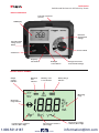
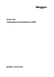
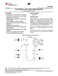
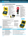
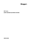
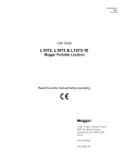
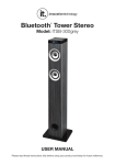
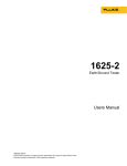
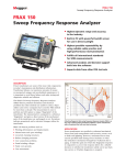
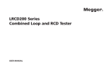
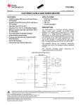
DET4 Series
4-Terminal Earth/Ground Resistance
and Soil Resistivity Testers
DESCRIPTION
Megger’s popular 4-terminal ground testing instrument
family includes four basic models with different kit variants
for each that include select accessories for greater testing
flexibility. The four basic units are:
Model
Description
DET4TD2
Dry-cell battery powered basic 4-terminal
tester
DET4TR2
Rechargeable battery powered basic
4-terminal tester
DET4TC2
Dry-cell battery powered 4-terminal tester
with selectable test frequencies, greater
measurement sensitivity and attached rod
technique and stakeless measurement
capability
DET4TCR2
Rechargeable battery powered 4-terminal
tester with selectable test frequencies,
greater measurement sensitivity and
attached rod technique and stakeless
measurement capability
The top-end models (DET4TC2 and DET4TCR2) include
a current measuring function for ART (Attached Rod
Technique) testing capabilities. With this added function,
on-site grounds can be tested separately without having to
remove the utility connection (as explained further in this
document). They also provide stakeless testing capability.
This method allows the operator to use the instrument
like a clamp-on ground tester in applications where that
method is viable, while also being able to operate as a fall
of potential tester if required.
1.800.561.8187
www.
n
2, 3 and 4 point testing
n
Stakeless (clamp-on) testing capability
n
ART (Attached Rod Technique) capability
n
Multiple, user selectable test frequencies
n
Resistance measurement range to
200,000 Ω
n
IP54 rated
n
Warning indicators prevent test failure
n
Simple one button operation
n
Included leads, stakes, calibration
certificate and rugged carry case
The basic kit includes the test leads, stakes, batteries and
calibration certificate, delivered in a tough polypropylene
carry case – everything you need to start testing in one
package.
All models are rated to IP54, making them truly outdoor
instruments. They are designed to meet stringent safety
standards and are rated CAT IV 100 V. The ground testers
have been designed to be easy to use – a large selector
switch makes selection of 2, 3 or 4 pole tests easy with
gloved hands – and the design makes the fitting of shorting
links to perform 2-pole tests a thing of the past. A large,
clear, easy to read LCD and thumb sized test button
also make the instruments particularly well suited to the
outdoor conditions of ground testing. In addition to this
ease of use feature, the instruments automatically check
the connection and conditions of the P spike, C spike,
and also the level of ground noise, indicating the status
on the display. They also include a voltmeter to enable
measurement of ground voltage.
The DET4TD2 and DET4TR2 can measure resistance from
0.01 ohms to 20 kΩ, while the DET4TC2 and DET4TCR2
can measure resistance from 0.01 ohms to 200 kΩ, a key
capability for soil resistivity testing. Also, to allow accurate
testing in noisy environments, the instruments are capable
of rejecting noise up to 40 V peak to peak.
The DET4TD2 and DET4TC2 are powered by eight AA
batteries which are widely available and also give excellent
testing time – the status of these batteries is given by a bar
graph on the LCD display, allowing the operator to decide
when to change the batteries before they expire. The
DET4TR2 and DET4TCR2 are powered from rechargeable
.com
[email protected]
DET4 Series
Earth/Ground Resistance & Soil Resistivity Testers
AA cells. The battery charger is built in and the instrument
is supplied with an AC/DC adapter. For all instruments, the
battery status is displayed using a bar-graph.
The DET4TC2 and DET4TCR2 include additional
capabilities. By using the optional ICLAMP the user can
augment the traditional fall-of-potential measurement
method with ART (Attached Rod Technique), which allows
electrode testing without disconnection and also leakage
current measurements down to 0.5 mA. A second optional
clamp, the VCLAMP, enables true stakeless (clamp-on)
measurements to be made in situations where driving
stakes is not practical.
The DET4TC2 and DET4TCR2 also feature a backlit
display, which extends the operational environment of
the instrument to cable cellars and other dark locations.
Finally, all units have selectable 25 V or 50 V output for
compliance with IEC 61557-5. The 25 V output is required
for testing in agricultural environments.
The maintenance of an adequate low resistance ground
connection is essential to both the protection and
performance of any electrical system. Ground testing
should be performed both upon installation, to meet
design specification, and periodically thereafter in order
to maintain service. All Megger models can also perform
bonding tests (using an ac signal), to determine that
adequate connection has been made from equipment to
the grounding system, and can perform soil resistivity
tests. This additional function can be used in prospecting,
locating, and designing new grounding electrodes and
systems. Furthermore, the addition of built-in current
clamp capability enables fall of potential testing of attached
grounds (ART) without lifting the utility connection and
the addition of voltage clamp technology enables stakeless
testing from the same instrument.
Grounding electrodes from simple to complex systems can
be tested, including:
n Primary and secondary electrical grounding systems
n Utility pole grounds
n Lightning protection systems
n Residential grounds
n Machinery safety grounds
n Computer and communication system grounds
n EMI/RFI system grounds
n Antenna and pedestal grounds
n CATV system grounds
FEATURES AND BENEFITS
testing capability, which allows the operator
to use the instrument like a clamp-on tester in applications where the method is viable
n Attached Rod Technique capability, which allows fall
of potential testing without the need to disconnect the
ground rod
n Multiple, user selectable test frequencies allows the
operator to find the most effective frequency for making
the measurement
n 200,000 Ω measurement range provides the ability to
measure the resistivity of any type of soil
n User selectable test voltage ensures that the units can be
used in agricultural environments
n Microprocessor control for improved error detection
n Clear, unambiguous warnings and error indications ensure the reliability of the reading and reduce test time
n Rugged, weatherproof case to IP54 makes the units truly
outdoor instruments
n Backlit LCD allows for testing in dark environments
n Noise rejection to 40 V pk to pk allows accurate testing
in noisy environments
n Testing kits and certificates supplied — everything
needed to start testing immediately
n Accuracy of 2% of reading enhances reliability of measurements
n Voltmeter function included allows you to measure the
ground voltage and enhances operator safety
n CAT IV 100V provides increased operator safety
n Stakeless
Model DET4TCR2 shown performing the stakeless ground testing method
using only clamps.
APPLICATIONS
Proper grounding provides many varied benefits to both
people and facilities. It lessens the chance of injury due
to faulty installation, reduces the likelihood of damage
from lightning strikes and induced voltages, improves
the performance of computer, communication and other
sensitive equipment and protects against static electricity
from friction. Over time, ground systems can degrade or
become ineffective. Corrosion and weather influences
exert mechanical strain on ground rods and cause metallic
corrosion. Catastrophic events like lightning strikes or large
fault currents can cause instant degradation. In addition,
soil resistivity can change over time due to environmental
conditions and facility expansion can create different
ground system needs.
The risks from ground system deterioration include
potentially deadly electrical shock situations, plant-wide
equipment damage, disruption in the performance of
sensitive equipment and heat build-up on a single piece of
electrical equipment.
1.800.561.8187
www.
.com
[email protected]
DET4 Series
Earth/Ground Resistance & Soil Resistivity Testers
SPECIFICATIONS
Resistance range: 0.01 to 200 kΩ autoranging
(0.01 to 20kΩ for models DET4TD2 and DET4TR2)
Resistance accuracy:
2P measurements
2% ±3 digits
3P measurements
2% ±3 digits
4P measurements
2% ±3 digits
ART measurements
5% ±3 digits
Stakeless measurements 7% ±3 digits
Maximum probe resistance:
DET4TD2 and DET4TR2
Rp limit: 100kΩ (50V output voltage)
Rc limit: 100kΩ (50V output voltage)
Limits reduced to 50kΩ for 25V output voltage
Limits reduced to 5kΩ for 0.01 Ω resolution
DET4TC2 and DET4TCR2
Rp limit: 200kΩ (50V output voltage)
Rc limit: 200kΩ (50V output voltage)
Limits reduced to 100kΩ for 25V output voltage
Limits reduced to 5kΩ for 0.01 Ω resolution
Earth voltage range: 0 – 100 V
Earth voltage accuracy: 2% ±2 V
2-wire test: Yes, all models
3-wire test: Yes, all models
4-wire test: Yes, all models
ART (Attached Rod Technique): DET4TC2, DET4TCR2
Stakeless test: DET4TC2 and DET4TCR2
Ground current range (with current measuring clamp):
0.5 mA to 19.9 A
Ground current accuracy: 5% ±3 digits
Display:
DET4TD2 and DET4TR2: 3-1/2 digit high contrast LCD
DET4TC2 and DET4TCR2: 3-1/2 digit high contrast LCD, backlit
STAKELESS (CLAMP-ON) TESTING
The DET4TC2 and DET4TCR2 include stakeless, or
clamp-on testing capability. In effect, these models can
be operated in the same way as a clamp-on ground
tester, eliminating the need to disconnect the ground
under test and drive test probes in certain ground system
testing applications. This method is also useful when
Test frequency: 94, 105, 111 and 128 Hz
(128 Hz for DET4TD2 and DET4TR2)
Test voltage: 25 V or 50 V, user selectable (factory setting 50 V)
Test current: 450 micro-amps at 25 V or 50 V (selectable),
4.5 mA at 25 V
Noise rejection: 40V pk to pk
Noise check: Automatic
C spike check: Automatic
P spike check: Automatic
Battery type: 8 1.5 V AA cells (8 1.5 V AA NiMH rechargeable
cells – DET4TR2 and DET4TCR2)
Battery life: 3 hours, 700 consecutive tests
Safety: EN61010-1 CAT IV 100 V
Terminals: 4 mm plug type (test leads)
Ingress protection: IP54
EMC: Meets the requirements of EN61326-1:1998 for use in heavy
industrial areas, including amendment 1
Dimensions: 8 x 5.7 x 3.2 in. (203 x 148 x 78 mm)
Weight: 2.2 lb (1 kg)
Operating temperature range: 5º to +131º F (-15º to +55º C)
Storage temperature range: -40º to +158º F (-40º to +70º C)
Humidity: 95% RH non-condensing at 104º F (40º C)
Standards Compliance
Complies with the requirements of KEMA K85B.
Complies with the following parts of EN61557, “Electrical safety
in low voltage distribution systems up to 1000 V a.c. and 1500 V
d.c. - Equipment for testing, measuring or monitoring of protective
measures”.
Part 1 - General requirements
Part 5 - Resistance to earth
there is insufficient space to perform a classic fall-ofpotential measurement. In addition the units can be used
to measure ground leakage or phase current.
The user simply clamps the optional ICLAMP (current
clamp) and VCLAMP (voltage clamp) around the ground
under test in the manner prescribed in the operator’s
manual and takes the reading. A defined test voltage is
injected into the system using the VCLAMP, inducing a
current, I, to flow and be measured by the ICLAMP. The
instrument then calculates the approximate resistance of
the ground under test.
The stakeless method is subject to the same limitations
faced by the traditional clamp-on ground tester. It is
effective only in situations with multiple grounds in
parallel and cannot be proofed like a fall-of-potential
test. In situations where the stakeless method reading is
questionable, a full fall-of-potential test is recommended.
The advantage of the DET4TC2 and DET4TCR2 is that the
units include both test methods in a single instrument,
making them the most versatile units available.
1.800.561.8187
www.
.com
[email protected]
DET4 Series
Earth/Ground Resistance & Soil Resistivity Testers
ART (ATTACHED ROD TECHNIQUE)
TESTING CAPABILITY
The DET4TC2 and DET4TCR2 include the additional
testing capability that we have termed ART, for Attached
Rod Technique. A nagging problem with traditional
ground testing has been the requirement to “lift” (i.e.,
disconnect) the utility connection. Once the grounding
conductor (the main conductor that connects the facility
to the ground rod or grid) has been attached to the
grounding electrode, the utility ground becomes a parallel
resistance. The utility neutral is typically bonded to the
ground bus at the service entrance and this connection,
during a ground test, causes test current to flow back
through the utility ground as well as through the test
electrode. Test current divides according to Law of Parallel
Resistance, but the tester makes its measurement based on
total current flow. The reading is the combined parallel
resistance of the on-site ground and the utility protection.
This is a valid measurement, but not of the test electrode
exclusively.
This poses a considerable problem in many common
testing situations. If a commissioning test were required to
determine if design specifications had been met for a new
facility, such a reading would be insufficient. Lightning
protection requiring a short, straight path into the earth,
could also not be properly validated. But lifting the utility
connection poses several problems, not the least of which
is the breaking of what is often a welded bond, in addition
to the temporary loss of protection.
Clamp-on ground testers, which measure ground
resistance by clamping around the rod and inducing a
test current onto it, are only a limited solution. They can
accurately measure resistance of a single rod in a parallel
system by inducing the test current onto the clamped
rod and utilizing all the parallel grounds as the return.
Collectively, these returns, typically the multiple grounds
of the utility, contribute little to the loop measurement.
This is essentially the reverse of the operation of a
traditional tester, which uses the current probe as
the return while current “goes to ground” through all
parallels collectively. This technique solves the problem
of separately measuring an attached rod, but leaves the
problem that it cannot be proven.
as acceptable grounds. The responsibility for making
these determinations falls squarely on the operator.
But even when properly addressed, there is no way of
demonstrating the competence of the readings to a third
party, such as a client. They must simply be accepted.
The ART testing capability combines the advantages of
both of these technologies to produce a method that
can reliably measure an attached ground, and prove
it! A built-in clamp input, used in conjunction with the
optional ICLAMP accessory, connected below the point of
separation of the parallel test currents, measures only the
current flowing through the test ground, not that going
back through the utility. This current value is then used by
the microprocessor to calculate ground resistance, strictly
in accordance with Fall of Potential or its derivative
procedures, supported by IEEE Standard 81 for proper
ground testing, and subject to the appropriate proofs.
The ART method employs leads and probes just as does
any traditional tester. Ground resistance can be profiled
and graphed by moving the potential probe against the
position of the current probe, and a Fall of Potential graph,
Slope Method mathematical proof, or any of the other
proven methods utilized to demonstrate the accuracy of
the test. The only thing different from the operation of a
familiar, traditional ground tester is that the clamp permits
separation of the test currents in an attached or otherwise
parallel-grounded system. This technique enables local
grounds to be tested without lifting the utility connection,
yet with the ease, reliability and confidence of a separate
commissioning test.
Current measuring clamp (inset)
for ART testing capability
A clamp-on measurement has to be accepted on faith
and its reliability is based squarely on the knowledge
and experience of the operator, leaving a large margin
for “human error.” In complex, multiply connected grids
and other grounding schemes, return paths may exist
that are entirely metallic, not including earth at all. The
clamp-on test current will circulate through such paths
and give a reading, essentially a continuity reading of the
grid structure having nothing to do with soil resistance.
Such readings will be low, and appear to the uninformed
1.800.561.8187
www.
.com
[email protected]
DET4 Series
Earth/Ground Resistance & Soil Resistivity Testers
SELECTION GUIDE
Tests
Output
Power Supply
Noise Rejection
Safety Rating
Ingress Protection
Included Accessories
Warranty
Model No.
DET4TD2 DET4TR2
DET4TC2
DET4TCR2
Cat. No.
1000-347
1000-324
1000-345
1000-346
2-Pole Measurement
n
n
n
n
3-Pole Measurement
n
n
n
n
4-Pole Measurement
n
n
n
n
Soil Resistivity
n
n
n
n
ART (Attached Rod n
n
Technique) Capability
Stakeless (Clamp-on) n
n
Measurement Capability
Resistance Range0.01 to 20,000 Ω0.01 to 200,000 Ω
Ground Voltage Range
0 to 100 V
Ground Current Range 0.5 mA to 19.9 A
(with ICLAMP) Capability
Selectable Voltage (25/50 V)
n
n
n
n
Test Frequency 128 Hz94, 105, 111, 128 Hz
Alkaline Batteries
n
n
Rechargeable Batteries
n
n
40 V Peak-to-Peak
n
n
n
n
CAT IV 100 V
n
n
n
n
Rated to IP54
n
n
n
n
Hard Carry Case
n
n
n
n
Test Leads (49 ft, 33 ft, n
n
n
n
33 ft, 10 ft) and Spikes
Certificate of Calibration
n
n
n
n
2 Year
n
n
n
n
CONFIGURATION OPTIONS
Rechargeable
batteries
Alkaline batteries
Power
Supply
Earth/ground kit,
C/N 6320-245
ICLAMP and
VCLAMP
Field Calibrator
External ac/dc
Adapter
Leads (49 ft, 33 ft,
33 ft, 10 ft) and Spikes
4 Right-angle
terminal adapters
Hard carry case
Included Accessories
Model No.
Cat. No.
DET4TC2+Clamps
1000-365
n
n
n
n
n
n
DET4TC2+Kit
1000-404
n
n
n
n
n
n
n
DET4TCR2+Clamps
1000-366
n
n
n
n
n
n
n
DET4TCR2+Kit
1000-405
n
n
n
n
n
n
n
n
*The Professional Ground Testing Kit (C/N 6320-245) includes two 164 ft (50 m) leads and two 98 ft
(30 m) leads on retractable reels, four auger-style ground spikes, a tape measure and a separate hard
carry case.
NOTE: Using the ICLAMP allows the operator to make ART measurements. Using the ICLAMP and
VCLAMP allows the operator to make stakeless (clamp-on) measurements.
1.800.561.8187
www.
.com
[email protected]
DET4 Series
Earth/Ground Resistance & Soil Resistivity Testers
DET4TC2 OPERATION
Test lead connections
(at rear)
LCD Display
Resistance
measurement
settings
25V / 50V output
voltage select
button
Selector switch
Test button
Frequency
select button
Backlight
control button
Voltage and current
measurement settings
DET4TC2 DISPLAY EXAMPLE
Output
voltage
indicator
Ruptured
fuse
indicator
Warning - refer
to user manual
Battery charge
indicator
Measuring
range
Over/under
range indicator
Potential probe resistance
indicator (OK or high)
1.800.561.8187
Current probe resistance
(OK or high)
www.
.com
Ground noise voltage
indicator (OK or high)
[email protected]
DET4 Series
Earth/Ground Resistance & Soil Resistivity Testers
OPTIONAL ACCESSORY KITS
Professional Kit
Cat. No. 6320-245
Red and black cable reels,
164 ft (50 m); yellow and
green cable reels, 98 ft
(30 m); earth electrode
leads, 13 ft (4 m) green;
4 mm shrouded plug and
large croc clip; 4 auger-style
spikes; molded polyethylene
carrying case; fiberglass
measuring tape, 164 ft (50 m)
Each instrument comes complete with three sets of leads, two test
spikes, instruction manual CD, and a rugged carrying case, (current
measuring clamp, shown, is an optional accessory for performing the
ART testing capability using the DET4TC2 and DET4TCR2 only.)
Soil Resistivity Kit
Cat. No. 250586
Set of four test leads, 50
ft. (15 m); two pair of 20
in. (51 cm) ground rods;
padded case to hold
instrument, leads and
rods
Deluxe Kit,
Cat. No. 250581
Terminal Adapters are used to
allow the DET4 Series units’
terminals to accept alternative
cable connections.
Set of three color-coded
test leads, 25, 50, 100 ft.
(8, 15, 30 m); two 20-in.
(51 cm) ground rods;
padded case to hold
instrument, leads and rods
Standard Kit,
Cat. No. 250579
Three color-coded test
leads, 25, 50, 100 ft.
(8, 15, 30 m); two 20-in.
(51 cm) ground rods;
canvas accessory case for
leads and rods only
Standard Kit
Cat. No. 6310-755
Hammer, 2.5 lb (1.13
kg); four galvanized steel
spikes, 0.5 in. (12 mm);
two spike extractors; four
leads in carrying case
1.800.561.8187
www.
.com
[email protected]
DET4 Series
Earth/Ground Resistance & Soil Resistivity Testers
ORDERING INFORMATION
Item (Qty)
Cat. No.
Item (Qty)
Cat. No.
DET4TD2
1000-347
Standard accessory kit (hammer, spikes, leads)
6310-755
DET4TR2
1000-324
DET4TC2
1000-345
Professional ground testing kit
(2 x 50m, 2 x 30m, 4 auger stakes, carry case)
6320-245
DET4TC2+Clamps
1000-365
DET4TC2+Kit
1000-404
DET4TCR2
1000-346
DET4TCR2+Clamps
1000-366
DET4TCR2+Kit
1000-405
Soil resistivity kit (leads, rods, padded case)
“Getting Down to Earth”
a Megger guide to earth testing
250586
AVTM25-TA
Replacement hard carry case
5410-429
Replacement calibration check PCB
(two-clamp measurements)
6220-831
Replacement ground test stakes (x2)
for included kit (200mm, 8mm dia)
6220-804
Replacement ground test leads (x4)
for included kit (15m, 10m, 10m, 3m)
6220-806
Voltage inducing clamp, calibration check PCB
(two-clamp measurements) and connecting lead VCLAMP
Replacement auger stakes (x2)
for professional kit
6220-839
Calibration check box
6220-824
Right angled terminal adaptor set
6220-803
Replacement cable reel (50m, red cable)
for professional kit
6220-840
Auxiliary 12V socket charger
(DET4TR2 and DET4TCR2 only)
6280-375
Replacement cable reel (50m, black cable)
for professional kit
6220-841
Replacement cable reel (30m, green cable)
for professional kit
6220-843
See Configuration Options chart for detailed information
Optional Accessories
Current measuring clamp and connecting
lead for ART testing method
ICLAMP
Standard accessory kit (leads, rods, canvas
accessory case for leads & rods)
250579
Deluxe accessory kit (leads, rods, padded case)
250581
UK
Archcliffe Road, Dover
CT17 9EN England
T +44 (0) 1 304 502101
F +44 (0) 1 304 207342
[email protected]
1.800.561.8187
UNITED STATES
4271 Bronze Way
Dallas, TX 75237-1019 USA
T 1 800 723 2861 (USA only)
T +1 214 333 3201
F +1 214 331 7399
[email protected]
www.
Replacement cable reel (30m, yellow cable)
for professional kit
OTHER TECHNICAL SALES OFFICES
Valley Forge USA, College Station USA,
Täby SWEDEN, Sydney AUSTRALIA,
Ontario CANADA, Trappes FRANCE,
Oberursel GERMANY, Mumbai INDIA,
Johannesburg SOUTH AFRICA, Aargau
SWITZERLAND, Chonburi THAILAND,
and Dubai UAE
.com
6220-842
ISO STATEMENT
Registered to ISO 9001:2000 Reg no. Q 09250
Registered to ISO 14001 Reg no. EMS 61597
DET4T2SERIES_DS_US_V05
www.megger.com
Megger is a registered trademark
[email protected]