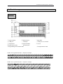
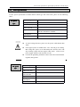
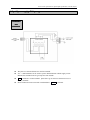
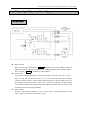
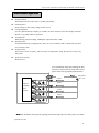
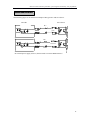
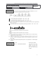
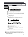
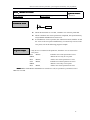
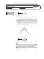
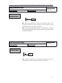
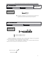
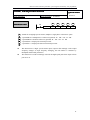
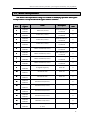
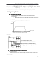
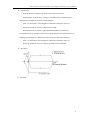
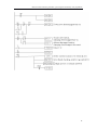
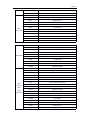
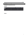
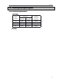
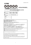
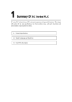
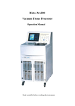
1
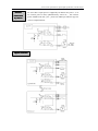
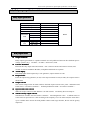
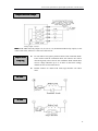
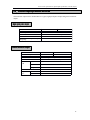
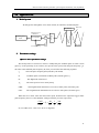
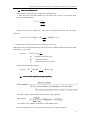
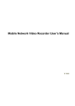
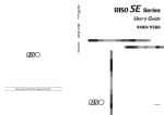
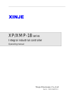
XCM motion control type PLC User manual Xinje Electronic Co., Ltd. Data number PC02 20080412 3.0 xinje electronic Catalog Foreword XCM ———————————————————— Motion control type PLC XCM motion control type PLC User manual summrize 1 ———————————————————— The power circuit specifications, input/output specifications and 2 external wiring ———————————————————— Action and function of various register, motion control instruction 3 explanation and parameters ———————————————————— Appendix ———————————————————— The first edition 4 This manual includes some basic precautions which you should follow to keep you safe and protect the products. These precautions are underlined with warning triangles in the manual. About other manuals that we do not mention, please follow basic electric operating rules. Precautions Correct Application Please follow the precautions. If not, it may lead the controlsystem incorrect or abnormal, even cause fortune lose. The models could only be used according to the manual, and an only be used along with the peripheral equipments recognized or recommended by Xinje Electronic. They could only work normally in the condition of be transported, kept and installed correctly, also please operate and maintain them according to the recommendation. Xinje Electronic Co., Ltd. Copyright reserved Without exact paper file allowance, copy, translate or using the manual is not allowed. Disobey this, people should take the responsibility of loss. We reserve all the right of expansions and their design patent. Duty Declare We have checked the manual, its content fits the hardware and software of the products.As mistakes are unavoidable, we couldn’t promise all correct. However, we would check the data in the manual frequently, and in the next edition, we will correct the necessary information. Your recommendation would be highly appreciated 20008.06 Catalog FOREWORD.............................................................................................................................................. 7 1.XCM MOTION CONTROL TYPE PLC SUMMARIZE.................................................................... 9 1-1.INTERNAL SPECIFICATION ............................................................................................................ 10 1-2.APPEARANCE & DIMENSION ........................................................................................................ 11 1-3.TERMINAL ARRANGEMENT.......................................................................................................... 12 1-4.COM PORT DEFINITION............................................................................................................... 13 2. POWER CIRCUIT SPECIFICATION, INPUT/OUTPUT SPECIFICATION, EXTERNAL LAYOUT.................................................................................................................................................. 21 2-1.POWER SPECIFICATION................................................................................................................. 23 2-2.AC POWER SUPPLY、DC INPUT TYPE.......................................................................................... 24 2-3.INPUT SPECIFICATION................................................................................................................... 21 2-4.DC INPUT SIGNAL’S DISPOSAL(AC POWER TYPE)................................................................ 22 2-5.RELAY OUTPUT SPECIFICATION AND CIRCUIT .............................................................................. 24 2-6.TRANSISTOR OUTPUT SPECIFICATION AND CIRCUIT ..................................................................... 26 3.MOTION CONTROL INSTRUCTION, PARAMETER, SPECIAL DATA REGISTER AND AUXILIARY RELAY EXPLANATION.................................................................................................. 29 3-1.SOFT ELEMENT ID LIST................................................................................................................ 31 3-2.MOTION CONTROL INSTRUCTION LIST (SPECIAL FOR XCM SERIES)........................................... 33 3-3.THE REDING NOTE OF APPLICATION INSTRUCTION .......................................................................34 3-4.MOTION CONTROL INSTRUCTIONS .............................................................................................. 35 3-5.MOTION CONTROL PARAMETER................................................................................................... 46 3-6.SPECIAL DATA REGISTER LIST...................................................................................................... 51 3-7.SPECIAL AUXILIARY RELAY LIST .................................................................................................. 52 3-8.APPLICATION CASE....................................................................................................................... 54 4.APPENDIX.........................................................................................................................................59 4-1.BASIC ORDER CONTROL INSTRUCTION LIST................................................................................. 61 4-2.APPLICATION INSTRUCTION LIST.................................................................................................. 63 4-3.SPECIAL FUNCTION INSTRUCTION LIST........................................................................................ 66 4-4.HIGH SPEED COUNTER DISTRIBUTION .......................................................................................... 67 4-5.EXTERNAL INPUT INTERRUPTION DISTRIBUTION ......................................................................... 68 Foreword Features of XCM motion control type PLC XCM motion control type PLC with the following features: The PLC integrate motion control function and ordinary PLC function in one XCM motion contol type PLC not only support proprietary function, but also support majority functions of ordinary PLC, including high speed pulse, high speed count, interruption, PID control, etc. Support at most 10-axes pulse output function XCM series contains 4-axes pulse output in common, specific model XCM-48 support at most 10-axes pulse output, maximize meet the users' control demands. Predominant motion control capability Can realize double-axes linkage, support familiar motion contol instructions, such as circular, linear interpolation, etc. Can do conversion on plane Support plane conversion instruction PLAN, can do double-axes linkage conversion on XY, Y-Z, X-Z, etc. Can expand XC series digital, analog module and BD board Similar with XC series, XCM series the same support module and BD board expansion, including digital, temperature anolog, etc. XCM serials including models: XCM-32RT-E:4-axes pulse output, transistor/relay mix type. XCM-48T-E:10-axes pulse output type. Supplement explanation: The instruction noted in this manual is motion control function instruction, for the rest instructions belong to XC series, such as generic order control, application or special function instruction, please see <<XC series PLC user manua>>. Remark XCM motion control type PLC summarize XCM motion control type PLC summarize 1.XCM The chapter focus on XCM series product general specifications, appearance and dimension, terminal arrangement and the definition of each communication pin. 1-1.Internal specification 1-2.Appearance and dimension 1-3.Terminal arrangement 1-4.The pin definition of communication port XCM motion control type PLC summarize Internal specification 1-1.Internal 1-1 General Items specification Insulate voltage Performance Up to DC 500V 2MΩ Anti-noise 1000V 1uS pulse per minute Ambient temperature 0℃~60℃ Ambient humidity 5%~95% COM 1 RS-232, connect with host machine、HMI program or debug COM 2 RS-232/RS-485, connect instrument、inverters etc. COM 3 BD board COM port RS-232C/RS-485 with network or aptitude Installation Can use M3 screw to fix or install directly on DIN46277 (Width 35mm) orbit Grounding The third type grounding (can’t public ground with strong power system.) XCM performance & specification table: & Specification Specifications Specification Item 32 points 48 points Program executing format Loop scan format, timing scan format Program format Instruction, C language, ladder chart Dispose speed 0.3us Power cut retentive Use FlashROM and Li battery User program’s capacity 8000 steps I/O points Interior coil’s points (M) Timer (T) Counter (C) Input 18 points Output 14 points Input 28 points Output 20 points 8512 points Points 620 points Spec. 100mS timer:Set time 0.1~3276.7 seconds 10mS timer:Set time 0.01~327.67 seconds 1mS timer:Set time 0.001~32.767 seconds Points 635 points Spec. 16 bits counter:set value K0~32767 32 bits counter:set value K0~2147483647 Data Register(D) 4512 words FlashROM Register(FD) 576 words High speed dispose High speed count、pulse output、external interrupt Setting of time scan space 0~99mS Password protection 6 bits ASCII Self diagnose function Power on self-diagnose、Monitor timer、grammar check Note: If choose "PLC Operation--Secret Download", "user program capacity" could be larger. XCM motion control type PLC summarize Appearance & dimension 1-2.Appearance 1-2 Appearance & (Unit: mm) Dimension XCM series 32-point main units 139 131 FG COM COM X1 X0 X3 X2 73.3 X5 X4 X6 X7 X10 X11 X13 X12 X14 X15 X16 X17 X20 X21 110 102 94 PWR XCM-32RT-ERUN PORT1 PORT2 ERR Y 0 1 2 3 4 5 6 7 24V 0V A COM0 B Y0 COM1 COM2 Y1 Y3 Y2 Y5 Y4 Y6 COM3 Y10 Y7 TYPE:XCM-32RT-E DATE:20060410 SN:0067032266 X Xinje Electronic Co.,Ltd 0 1 2 3 4 5 6 7 COM4 Y13 Y15 Y11 Y12 Y14 3.5 XCM series 48-point main units 207.4 199.4 X1 COM COM X0 X3 X2 X5 X4 X7 X6 X11 X10 X13 X12 X15 X14 73.3 X17 X16 X21 X20 X23 X22 X25 X24 X27 X26 X31 X30 X33 X32 XCM-60RT-E RUN ERR PORT2 Y 0 1 2 3 4 5 6 7 24V 0V CAN+ A CAN- B COM0 Y0 COM1 Y1 COM2 Y2 COM3 Y3 COM4 Y4 COM5 Y5 Y6 Y7 COM6 Y10 Y11 Y12 Y13 COM7 Y14 Y15 Y17 Y16 COM8 Y20 Y21 Y22 Y23 TYPE:XCM-60RT-E DATE:20060410 SN:0067032266 PWR X PORT1 Xinje Electronic Co.,Ltd 102 94 0 1 2 3 4 5 6 7 XCM motion control type PLC summarize Terminal arrangement 1-3.Terminal 1-3 Main units ① Input terminals ② BD expansion ④ COM port ⑤ COM port ⑦ Output label ⑧Output terminals ⑩ Input indicate LED ⑾ Extension port ⑿Programming status indicate LED ③ Input label ⑥ COM port’s cover board ⑨ Screws ⒀ Output indicate LED XCM series 48-point main units:28 Input /20 Output COM COM 0V 24V CAN+ A X0 CAN- B X1 X2 COM0 X3 Y0 X4 COM1 X5 Y1 X6 COM2 X7 Y2 X10 X11 Y3 COM3 X12 X13 X14 X15 X16 X17 X20 X21 X22 X23 X24 X25 X26 X27 X30 X31 X32 X33 Y4 COM5 Y7 Y10 Y12 COM7 Y15 Y17 Y20 Y22 COM4 Y5 Y11 Y13 Y6 COM6 Y14 Y16 COM8 Y21 Y23 XCM series 32-point main units:18 Input /14 Output FG 24V 0V COM A COM COM0 B X0 Y0 X1 COM1 X2 X3 X4 X6 Y3 COM2 Y1 X5 Y2 Y4 X7 Y5 X10 X11 COM3 Y6 X12 Y7 X13 Y10 X14 X15 X16 X17 X20 X21 COM4 Y13 Y15 Y11 Y12 Y14 XCM motion control type PLC summarize COM Port definition 1-4.COM 1-4 Port 1 Pin of COM 1: 1 2 3 4 6 5 8 7 2:PRG 4:RxD 5:TxD 6:VCC 8:GND Mini Din 8 core socket (hole) Port 2 Pin of COM 2: 1 2 3 4 6 5 7 8 4:RxD 5:TxD 8:GND Mini Din 8 core socket (hole) Program cable Connection of programmable cable as the following: 5 2 1 5 43 8 6 7 Mini Din 8core socket (pin) 1 9 6 DB 9 pin (hole) Power circuit specification, input/output specification, external layout Power circuit specification, input/output specification, external layout 2.Power This chapter focus on XCM PLC power composing, internal signal circuit composing, output circuit composing and external layout method. 2-1.Power specification 2-2.AC power supply, DC input type 2-3.Input specification 2-4.DC input signal disposal (AC power supply type) 2-5.Output specification 2-6.Relay output circuit diaposal 2-7.Transistor output circuit disposal Power circuit specification, input/output specification, external layout Power circuit specification, input/output specification, external layout Power specification 2-1.Power 2-1 For the power specification of XCM motion control type PLC basic units, please see the following table: AC power type Rated voltage AC100V~240V Voltage allow bound AC90V~265V Rated frequency 50/60Hz Allow momentary power-cut time Impact current Interrupt time≤0.5 AC cycle,alternation≥1 sec Max power consumption Power for sensor use DC power type Max 40A 5mS below/AC100V max 60A 5mS below /AC200V 12W 24VDC±10% max 400mA To avoid voltage decrease, please use the power cable thicker than 2mm2 Even appear power cut within 10ms,PLC can still go on working. But if long time power cut or abnormal power decrease, PLC will stop working, output will also appear OFF status , when recover power supply, the PLC will auto start to work. Connect the grounding terminals of basic units and extend modules together, then ground Rated voltage DC24V Voltage allow bound DC21.6V~26.4V Input current (Only basic unit) Allow momentary power-cut time Impact current 120mA DC24V Max power consumption Power for sensor use 12W 10mS DC24V 10A DC26.4V 24VDC±10% Max 400mA Power circuit specification, input/output specification, external layout AC power supply DC input type 2-2.AC 2-2 supply、DC Constitution and Connection · The power is connected between L and N terminals. 24+、COM terminals can be used as power 400mA/DC24V which supply sensor. · Besides, this terminal can’t be given power from outside. terminal is vacant terminal,please don’t go on exterior connection or use it as relay terminal. Please connect the basic unit with extend module’s COM terminal. Power circuit specification, input/output specification, external layout Input specification 2-3.Input 2-3 Basic Units Model XCM-32RT/XCM-48T Input signal’s voltage DC24V±10% Input signal’s current 7mA/DC24V Input ON current Up to 4.5mA Input OFF current Low than 1.5mA Input response time About 10ms Input signal’s format Contact input or NPN open collector transistor Circuit insulation Optical-coupled insulation Input action’s display LED light when input ON Expansions Model XCM-32RT/XCM-48T Input signal’s voltage DC24V±10% Input signal’s current 7mA/DC24V Input ON current Up to 4.5mA Input OFF current Below 1.5mA Input response time About 10ms Input signal’s format Contacts input or NPN open collector transistor Circuit insulation Optical-coupled insulation Input action’s display LED light when input ON. Power circuit specification, input/output specification, external layout DC Input Signal AC Power Type 2-4.DC 2-4 Signal’’s Disposal Disposal(AC Type) DC input signal Input terminal When connect input terminal and COM terminal with contacts without voltage or NPN open collector transistor, if input is ON,LED lamp lights, which indicates input。 There are many COM terminals to connect in PLC. Input circuit Use optical coupling instrument to insulate the input once circuit and twice circuit , There’s a C-R filter in the twice circuit 。 It is set to avoid wrong operation caused by vibration of input contacts or noise along with input signal. As the preceding reason, for the changing of input ON→OFF,OFF→ON,in PLC, the response time delays about 10ms。There’s a digital filter inside X000~X015。This kind of filter can very from 0~15ms according to the special register (D8020). Input sensitive The PLC’s input current is DC24V 7mA,but to be safe,it needs current up to 3.5mA when it’s ON,lower than 1.5mA when it’s OFF. Power circuit specification, input/output specification, external layout Exterior circuit used by sensors Input Connection XC series PLC’s input power is supplied by its interior 24V power,so if use exterior power to drive photoelectricity sensor etc., , this exterior power should be DC24V±4V,please use NPN open collector type for sensor’s output transistor Power circuit specification, input/output specification, external layout 2-5 Relay output specification and circuit 2-5.Relay Relay output specification Model Relay output bit External power Circuit insulation Action denote Resistant load Maximum Induce load load Lamp load XCM-32RT Y12,Y13,Y14,Y15 AC250V、DC30V 以下 Mechanism insulation LED indicate lamp 3A Minimum load Response OFF→ON time ON→OFF DC5V 2mA 10ms 10ms XCM-48T Blank 80VA 100W Relay output circuit Output terminals Relay output type includes 2~4 public terminals. So each public-end unit can drive different powervoltage system’s (E.g.:AC200V,AC100V,DC24V etc.) load. Circuit’’s insulation Circuit Between the relay output coils and contacts,PLC’s interior circuits and exterior circuits, load circuits are electric insulation. Besides, each public-end blocks are separate. Action display LED lamp lights when output relay’s coils galvanize, output contacts are ON. Response time From the output relay galvanize (or cut) to the output contacts be ON (or OFF), the response time is about 10ms Output current The current-voltage below AC250V can drive the load of pure resistace 2A/1 point、inductance load below 80VA(AC100V or AC200V) and lamp load below 100W(AC100V or AC200V). Open circuit circuit’’s leak current When the output contact be OFF and there’s no leak current,can directly drive Ne lamp etc. The life of relay output contacts Standard life of induce AC load such as contactor、electromagnetism valve :5 million times for 20VA load. Cut power device’s life according to the company’s test: for 80VA load, the action life is up to 2 million times. But if the load parallel connect with surge absorber, the life will be greatly improved! Power circuit specification, input/output specification, external layout Output connection example Note: XCM-32RT with relay output Y12, Y13,Y14, Y15; XCM-48T without relay output, so can't connect with 220V, otherwise it will cause short-circuit. Output circuit composing For DC induce load, please parallel connect with commutate diode. If not connect with the commutate diode, the contact’s life will be decreased greatly. Please choose the commutate diode which allow inverse voltage endurance up to 5~10 times of the load’s voltage, ordinal current exceeds load current. Parallel connect AC induce load with surge absorber can reduce noise. DC load AC load 25 Power circuit specification, input/output specification, external layout Transistor output specification and circuit 2-6.Transistor 2-6 The transistor output can be divided into two types, high speed pulse output and generic transistor output. High speed pulse output Model High speed pulse output bit External power Action denote Maximum current The maximum pulse output frequency XCM-32RT Y0~Y3 XCM-48T Y0~Y11 Below DC5~30V LED indicate lamp 50mA 400KHZ Generic transistor output Model Transistor output bit External power Circuit insulation Action denote Maximum Resistant load load Induce load Lamp load Minimum load Response OFF→ON time ON→OFF XCM-32RT Y4~Y11 XCM-48T Y12~Y23 Below DC5~30V Optical-coupled insulation LED indicate lamp 0.8A 12W/DC24V 1.5W/DC24V DC5V 2mA Below 0.2ms Below 0.2ms 26 Power circuit specification, input/output specification, external layout Generic transistor output circuit Output terminal The transistor of basic units with 1~4 public-end output. External power Please use DC5~30V steady-voltage to drive load. Circuit insulation Use the photoelectricity-coupling to insulate the PLC internal circuit and output transistor. Beside, every public block is separated. Action denote When driving optical-coupling, LED lights, output transistor is ON. Response time From photoelectricity coupling device drive (or cut) to transistor ON (or OFF), the time PLC uses is below 0.2ms. Output current The current is 0.5A per point。But as restrict of temperature rising, the current is 0.8A every four points. Open circuit current Below 0.1mA. To avoid burning为防止负载短路等故障烧坏 output unit, burning the PLC 输出单元,烧坏可编程控制 substrate wiring caused by load short-circuit, 器的基板配线,请选用合适 please choose the各负载的保险。 appropriate load insurance. 1A 负载 Load Y*4 Optical 光 耦 coupling 驱 drive 动 circuit 电 路 DC power DC电源 DC5~30V Load 负载 Y*5 Load 负载 Y*6 Load 负载 Y*7 Note: For XCM-48T, when optical coupling point connecting with power load, please use output (Note: point Y12~Y23). 27 Motion control instruction, parameter, special register and auxiliary relay explanation Connect with servo driver The following figure is an connection example of RT type PLC and servo driver. PLCside Servo driver 2KΩ PUL- Y0 脉冲 pulse PUL+ DC24V 2KΩ DIR- Y4 方向 Direction DIR+ DC24V (If external power supply is DC5V, then no need to connect 2KΩresistance.) 28 Motion control instruction, parameter, special register and auxiliary relay explanation 3 . Motion control instruction, parameter, special data register and auxiliary relay explanation The chapter focus on XCM motion control instruction function, motion control parameter, special data register and auxiliary relay. In the end chapter, we select two examples for reference. 3-1.Soft element ID list 3-2.Motion control instruction list 3-3.Instruction explanation reading method 3-4.Motion control instruction explanation 3-5.Motion control parameter list 3-6.Special data register list 3-7.Special auxiliary relay list 3-8.Application case 29 Motion control instruction, parameter, special register and auxiliary relay explanation 30 Motion control instruction, parameter, special register and auxiliary relay explanation Soft element ID list 3-1.Soft 3-1 XCM series soft element ID allocateddistribute as follows. Besides, when connect input, output expansion device and special expansion device with basic units, for the input/output relay NO., please see user manual. .. Mark Name X Y M S 48 points 32 points 48 points Input point X000~X021(Octal ) X000~X033(Octal) 18 points 28 points Output point Y000~Y015(Octal) Y000~Y023(Octal) 14 points 20 points Flow C Counter ED M0~M2999【M3000~M7999】 8000 Special use M8000~M8511 512 S0~S511 【S512~S1023】 1024 Internal relay Timer FD Points 32 points T D Range T0~T99:100ms not cumulation T100~T199:100ms cumulation T200~T299:10ms not cumulation T300~T399:10ms cumulation T400~T499:1ms not cumulation T500~T599:1ms cumulation T600~T618:1ms with interruption, precise timing C0~C299:16 bits forth counter C300~C598:32 bits forth/back counter C600~C634:high speed counter D0~D2999 【D4000~D4999】 620 635 4000 Data register Special use D8000~D8511 512 FD0~FD63 64 Special use FD8000~FD8349,FD8890~FD8950 410 ED0~ED36863 36864 FlashROM register Expansion internal register 31 Motion control instruction, parameter, special register and auxiliary relay explanation NOTE NOTE: ※1. The memorizer area in【 】 is the defaulted power failure retentive area;soft elements D、M、S、T、C can be set to change the power failure retentive area. For the details, please see the following table ※2. FlashROM register needn’t set power failure retentive, its data won’t lose when power is cut (No battery). ※3. The serial No. of input coil、output relay are octal data, other memorizers’ No. are all algorism data. ※4. The exterior device which is not connected with I/O can be used ad fast-speed interior relay. Soft element power-off retentive area settings Name Set area D FD8202 M FD8203 T FD8204 C FD8205 S FD8206 ED FD8207 Function Start denotation of D poweroff retentive area Start denotation of M poweroff retentive area Start denotation of T poweroff retentive area Start denotation of C poweroff retentive area Start denotation of S poweroff retentive area Start denotation of ED power-off retentive area System default value Power-off retentive range 4000 D4000~D4999 3000 M3000~M7999 620 Not setted 320 C320~C635 512 S512~S1023 0 ED0~ED36863 32 Motion control instruction, parameter, special register and auxiliary relay explanation Motion control instruction list (Special for XCM series) 3-2.Motion 3-2 DRV High speed positioning LIN Linear Interpolation Positioning CW Circular clockwise interpolation CCW Circular anticlockwise interpolation DRVZ Machine zero return CHK Servo end check DRVR Electrical zero return SETR Electrical zero settings TIM Delayed time ABS Absolute address INC Incremental address SETP Set reference frame PLAN Plane selection FOLLOW Following movement instruction 33 Motion control instruction, parameter, special register and auxiliary relay explanation The reding note of application instruction 3-3.The 3-3 ① ② ④ ③ ⑤ ⑥ Note : ① ② ③ ④ ⑤ Instruction name 16 bits instruction and 32 bits instruction Ladder chart illustration Applicable models S· It denotes that the operand don't change with instruction implementation, called source operand. D· It denotes that the operand change with instruction implementation, called target operand. ⑥ Successively explain the instruction's basic movement, use method, application example, expansion function, notice point, etc. 34 Motion control instruction, parameter, special register and auxiliary relay explanation Motion Control Instructions 3-4.Motion 3-4 DRV: High Speed Positioning 16Bits Instruction: -- 32 Bits Instruction: Below Suitable Model: XCM-32 Function & Action M0 DRV S1 S2· k1 0 0 0 k1 0 0 ● X axes and Y axes high speed positioning with the maximum speed: S1· X axes target position; operands: K、TD、CD、D、FD. S2· Y axes target position; operands: K、TD、CD、D、FD. The instruction specifies the travel to the target coordinates with independent settings for the X and Y-axes. This instruction doesn’t realize interpolation function. Each axes’s maximum speed is specified by parameter register FD8908; acceleration/deceleration speed is determined by acceleration time parameter FD8910 and deceleration parameter FD8912.. Whether the position is incremental (distance from the zero point) or absolute (distance from the zero point) is specified by instruction ABS, INC. When the target position, operate speed are specified by indirect registers, the system default them as double words. Program Example INC DRV K1000 K2000 ;Incremental Drive Method; ;High speed positioning with the maximum speed, the target address is: (1000,2000); 35 Motion control instruction, parameter, special register and auxiliary relay explanation LIN: Linear Interpolation Positioning 16bits instruction:-- Function & Action 32bits instruction: Below Suitable Model: XCM-32 The instruction moves the machine to the target coordinates (X, Y) in a linear route by using the both axes at the same time. X axes target position. Operands: K、TD、CD、D、FD. Y axes target position. Operands: K、TD、CD、D、FD. S3· The third axes target position. Operands: K、TD、CD、D、FD. (Note: This instruction is not available for tri-axes control. The value set here is ignored, but this bit is reserved.) When X axes without setting operation speed, it will take linear interpolation positioning in high S4 Operation speed of linear interpolation positioning. Operands: K、TD、CD、D、FD. speed. S1 S2· M0 L IN S· D· k1 0 0 0 k1 0 0 0 X axes target position. Operands: K, TD, CD, D, FD. Y axes target position. Operands: K, TD, C D, D, FD. This instruction moves the machine to the target coordinates (X, Y) in a linear route by using the both axes at the same time. Whether the target position is incremental (indicating the distance from the current position) or absolute (indicating the distance from the coordinate zero point) is set by INC or ABS. When the target position and operation speed are set by parameters, it is double digital operation. Program example ABS LIN K1000 K2000 K0 K5000 Absolute drive method; This instruction moves the machine to the target position (1000,2000) in a linear route with the speed of 5KHz. 36 Motion control instruction, parameter, special register and auxiliary relay explanation Circular interpolation CW/CCW:Circular CW/CCW 16 digit instructions-- Function & Action 32 digit instructions:The following Circular interpolation with center point specification S1 S2 S3 S4 S5· S6 k1 0 0 k1 0 0 k1 0 0 k1 0 0 k1 0 0 k1 0 0 M0 CW S1· Applicable model XCM-32 X axes target position, operands: K、TD、CD、D、FD. Y axes target position, operands: K,TD、CD、D、FD. center point specification X axes position, operands: K、TD、CD、D、FD. center point specification Y axes position, operands:K、TD、CD、D、FD. The third axes position, operands:K、TD、CD、D、FD. (Notice: three axes’s movement control is not open, so the setting value with no function but reverse it.) Circular peripheral speed , operands: K、TD、CD、D、FD. S2· S3 S4 S1· S5 S6 Without peripheral speed, takes specification highest speed, as following. M0 CW S1 S2 S3 S4 k1 0 0 k1 0 0 k1 0 0 k1 0 0 Circular interpolation, specification radius. M0 S1· S2· S3 S4 S1· CW S1 S2 S3 S4 S5 k1 0 0 k1 0 0 k1 0 0 k1 0 0 k1 0 0 0 X axes target position, operands:K、TD、CD、D、FD. Y axes target position , operands:K、TD、CD、D、FD. Circular radius, operands:K、TD、CD、D、FD. The third axes movement control , operands: K、TD、CD、D、FD. (Notice: three-axes movement control is not open, so the setting value with no function but reverse it.) Circular peripheral speed , operands: K、TD、CD、D、FD. Without peripheral speed, takes specification highest speed, as following. CW is clockwise interpolation operation, CCW is anticlockwise interpolation operation. The radius is always treated as an incremental address from the center point of X/Y. the acceleration/deceleration time constant and the unit of peripheral speed are set by parameters of FD8910, FD8912. 37 Motion control instruction, parameter, special register and auxiliary relay explanation Whether the target position is an incremental or absolute is set by code INC or ABS. Target position, operation speed setting by parameters, specification unit is double operation. When the start point is equivalent to the end point or when the endpoint coordinates, the travel locus makes a complete circle. Program example ABS CW K1000 K500 K200 K0 K5000 Specification absolute speed This instruction specifies the travel to the target position (1000,500) from the start position (600,500) around the center incremental address (2000,0) at the peripheral speed 5KHz,the travel locus shown as blow. 38 Motion control instruction, parameter, special register and auxiliary relay explanation Machine zero return DRVZ:Machine DRVZ 16-bit function:-- 32-bit function:-- Function & Action X0 Applicable models: XCM-32 DRVZ When the instruction is executed, a machine zero return is performed. When a machine zero return operation is completed, the special auxiliary relays M8269 and M8270 are return to on. In simultaneous 2-axis operation ,this instruction returns both the X and the Y axis to the zero point simultaneously. To return only one axis to the zero point, refer to the following program example. (Only X axes is returned to the point first, then the Y axes is return to the zero point) SET M8262 ; Prohibits zero return operation of 1axes. DRVZ; Returns X axes only to zero point. RST M8262; Allows zero return operation of 1 axes. SET M8261; Prohibit zero return operation of 0 axes. DRVZ; Returns 1 axes only to zero point. RST M8261; Allows zero return operation of 0 axes. Notice: When both M8261 and M8262 are turned on or off, no operation is performed even if DRVZ is executed. Program example 39 Motion control instruction, parameter, special register and auxiliary relay explanation Servo end check CHK:Servo CHK 16-bit instructions:-- 32-bit instructions:-- Function & Action CHK Applicable models XCM-32 ● When interposal the CHK in the two operation control instructions, the travel will stop at the specification point, when interpolation operation continues, the machine performs non-stop operation and inflection points make a smooth curve. ● When you would like to move the machine from the target position A to the B position and then to the C position, interposal the CHK instruction between the two LIN instructions, the travel curve shown by the figure in the below, otherwise it shown by broken line. B C A S1 CH K M1 0 0 :CHK instruction operation winding, operands: X、Y、M、S、 T、C. ● After the CHK takes with winding (such as specification winding M100), after execute CHK instruction, until specification winging is on, execute next control operation. ● If the specification winding is on, its function equal to the CHK instruction with out winding. S1· 40 Motion control instruction, parameter, special register and auxiliary relay explanation Electrical zero return DRVR:Electrical DRVR 16-bit instruction:-- 32-bits instruction:-- Applicable models XCM-32 Function & Action X0 DRVR ● When this instruction is executed, the machine returns to the electrical zero point (set to the electrical zero point register) at high speed, and the servo end check is performed. ● The acceleration/deceleration time is determined by parameter FD8910 and parameter FD8912, and the operation speed is determined by parameter FD8912. Electrical zero settings SETR:Electrical SETR 16-bit instruction:-- 32-bit instruction:-- Applicable models XCM-32 Function & Action M0 SETR ● When this instruction is executed, the current place (saved in current register) will be writed into electrical zero register. 41 Motion control instruction, parameter, special register and auxiliary relay explanation TIM Delayed time (Dwell) TIM:Delayed 16-bit instruction:-- 32-bit instruction: remarks Function & Action S1 X0 S1· Applicable models XCM-32 T IM K 1 0 0 0 stabilization time(Dwell),operands:K、TD、CD、D、FD. Use this instruction to set the waiting time between completion of one instruction and execution of another. Time TIM ● Unit is 1ms,such as K1000 stands for 1ms dwell. ● The value of dwell time set by data register indirectly. Default is double bits operation. Absolute address ABS:Absolute ABS 16-bit instruction:-- 32-bit instruction:-- Function & Action A BS Applicable models XCM-32 The address coordinates(X,Y) used after the ABS instruction are regard as absolute values from the zero point(0,0). However, the coordinates of the arccenter point (I, j), the radius (r),the travel are always regarded as incremental values. An address is regard as an absolute value when specification is omitted. 42 Motion control instruction, parameter, special register and auxiliary relay explanation Incremental address INC:Incremental INC 16-bit instruction:-- Applicable models XCM-32 32-bit instruction:-- Function & Action IN C ● The address coordinates (X, Y) used after the INC instruction are regarded as incremental values from the present position. Set coordinate system SETP:Set SETP 16-bit instruction:-- 32-bit instruction:The following Function & Action S1 M0 SETP S1· K1 0 0 0 S2 K1 0 0 Set new coordinate of X axes. Set new coordinate of Y axes. S2· When this instruction is executed, the value in current register change into the appointed value.After that, both machine zero and eletrical zero have changed. The current place is (200, 200)(absolute coordinate), after executing "SETP k100 k100" instruction, the new and old zero point changed as shown below: y 200 y 100 The new zero point 旧零点 The old zero point 新零点 100 200 x x 43 Motion control instruction, parameter, special register and auxiliary relay explanation Plane or space selection PLAN:Plane PLAN 16-bit instruction:-- 32-bit instruction:The following Function & Action M0 PLA N S1 S2 K0 K1 S1· Set the tab axes (K0 denote X0, K1 denote X1, Kn denote Xn) as X axes, the following motion control instructions will take this axes as operation axes. S2· Set the tab axes (K0 denote Y0, K1 denote Y1, Kn denote Yn) as Y axes, the following motion control instructions will take this axes as operation axes. Program example LD M0 LD M0 PLAN K1 K2 SETP K10000 K20000 Respectively set Y1,Y2 as 1 axes and 2 axes Change the current register value of 1 axes and 2 axes into 10000 and 20000 Note: without using PLAN instruction to appoint axes, the system default Y0,Y1 as operate axes.) (Note: 44 Motion control instruction, parameter, special register and auxiliary relay explanation Following movement instruction FOLLOW:Following FOLLOW 16-bit instruction:-- Function & Action 32-bit instruction:As follows S1 M0 FOLLOW S1· S2· S3 S4 S1· S5 Applicable models XCM-32 C6 3 0 S2 S3 S4 S5· K1 0 K2 0 Y0 Y1 : Stands for using high-speed counter, AB phase, single phase or direction +pulse : Operand K10 is multiplicative coefficient ,operands : K、TD、CD、D、FD. : Operand K20 is divided coefficient ,operands: K、TD、CD、D、FD : Operand Y0 is output pulse terminal port NO. : Operand Y1 is output pulse direction terminal port NO. This instruction is a high –speed counter input, output it after multiply it. The output frequency changes as input frequency changing, the tall number is calculate by multiplied and divided parameters. The instruction is used for multiply or divide the high-speed pulse then output it from port Y0 or Y1. 45 Motion control instruction, parameter, special register and auxiliary relay explanation Motion control parameter 3-5.Motion 3-5 The motion control parameter settings are realized via modifying speical FLASH register. Each parameter correspond with XCM register address as follows: PARA NO. Special register Name Description Default value 1 FD8892 FD8893 Pulse rate (0 axes) Pulse number per revolution 0 2 FD8894 FD8895 Pulse rate (1 axes) Pulse number per revolution 0 3 FD8896 FD8897 Pulse rate (2 axes) Pulse number per revolution 0 4 FD8898 FD8899 Pulse rate (3 axes) Pulse number per revolution 0 5 FD8900 FD8901 Motor resolution(0 axes) Move distance per revolution 0 6 FD8902 FD8903 Motor resolution(1 axes) Move distance per revolution 0 7 FD8904, FD8905 Motor resolution(2 axes) Move distance per revolution 0 8 FD8906 FD8907 Motor resolution(3 axes) Move distance per revolution 0 9 FD8908 FD8909 Assigned frequency Unit: Hz 0 10 FD8910 FD8911 Accelerate time Unit: ms 0 11 FD8912 FD8913 Decelerate time Unit: ms 0 12 FD8914 FD8915 Electrical zero(0 axes) 0 13 FD8916 FD8917 Electrical zero(1 axes) 0 14 FD8918 FD8919 Electrical zero(2 axes) 0 15 FD8920 FD8921 Electrical zero(3 axes) 0 16 FD8922 FD8923 Machine zero(0 axes) 0 17 FD8924 FD8925 Machine zero point (1 axes) 0 46 Motion control instruction, parameter, special register and auxiliary relay explanation 18 FD8926 FD8927 Machine zero point(2 axes) 0 19 FD8928 FD8929 Machine zero point(3 axes) 0 20 FD8930 FD8931 Machine zero point frequency 0 21 FD8932 FD8933 Machine zero point return creep speed Interruption trigger 22 23 24 FD8934 FD8935 FD8936 External input X2 (X axes) External input X10 (Y axes) 0 axes creep speed The pulse number(Z phase) at zero point(which need to be count) 1 axes creep speed The pulse number(Z phase) at zero point(which need to be count) 2 axes creep speed The pulse number(Z phase) at zero point(which need to be count) 0 0 External input X5 (X axes) External input X11 (Y axes) 0 0 25 FD8937 3 axes creep speed The pulse number(Z phase) at zero point(which need to be count) 26 FD8938 Machine zero point return settings See table (3-5-1) 0 27 FD8940 Zoom in ratio coefficient (power of 2) 0 0 The following is the detailed explanation of motion control parameters: 1: Pulse rate PARA. PAR A.1 Set the number of pulses per revolution of the motor to be given to the drive unit. Setting range: 1 to 65535 PLS (pulse)/REV(revolution) When the servomotor is equipped with an electronic gear, its magnification should be taken into account. The relationship between the pulse rate and the electronic gear is as follows: Pulse rate (PARA.1)=Resolution of encoder (positioning feedback pulse)/electronic gear 2, PA RA. 3, PA RA. 4 respectively set the number of pulses per rotation the motor PARA.2 PARA. PAR A.3 PAR A.4 to the drive unit of 1ax e s, 2ax e s, 3ax 1axe 2axe 3axees. The basic settings is the same as PARA.1. PARA.5: Feed rate PARA.5 Set the travel of the machine per rotation of the motor Setting range :1~999999(um/REV,mdeg/REV,minch/REV) 7, PARA. 8 respectively set the travel of the machine rotation of the PARA.6, PAARA. PARA.6 PAARA.7 PARA.8 47 Motion control instruction, parameter, special register and auxiliary relay explanation specification 1 axes axes,, 2 axes axes,, 3 axes of the motor motor.. The basic settings is the same as PARA.1. PARA.9: Maximum speed PARA.9 Set the maximum speed in this parameter. When the speed is not specified in a positioning program, the machine operates at the speed set here. Other speeds must be set to a value equivalent to or less than this maximum value. Setting range: 0~20000 Hz PARA.1 0: Acceleration time PARA.10 Set the time required to achieve the maximum speed Setting range: 0~5000ms When PARA.10 is set to 0,the machine actually accelerates in 1 ms. PARA.11: Deceleration time PARA.11 Set the time required to stop the machine. Setting range:0~5000ms When PARA.11 is set to 0, the machine actually accelerates in 1 ms. PARA.12: 0 axes electronic zero point address The units of the set value are determined by DRVR instruction. Setting range:-999999 to +999999 The value set here is treated as an absolute address. 4, PARA.1 PARA.13, PARA.1 PARA.13 PARA.14 PARA.155 set the machine zero point absolute addresses on 1ax 1axees,2 axes,, 3 axes axes axes.. PARA.16: Machine zero point address PARA.16: When the zero return operation is complete, set the present address at which the machine is placed. Setting range:-999999 to +999999 8, PARA. 19 set the machine zero point address on 1 axes PARA.17, PARA.1 PARA.17 PARA.18 PARA.19 axes,, 2 axes axes,, 3 axes.. axes PARA20: Machine zero return speed PARA20 Set the speed adopted when the machine is returning to the zero point, the set value must be equivalent to or less than the maximum speed set to PARA.9 Setting range:10 to 50000 Hz. PARA.21: Machine zero return creep speed PARA.21 Set the low speed adopted after the near-point DOG1 signal is turn on. Setting range: 10 to 50000 Hz 22: Zero point signal count (Z phase) PARA.22: PARA.22 count(Z 48 Motion control instruction, parameter, special register and auxiliary relay explanation Set the number of zero point to be counted after the DOG2 signal (X11 switch input) is turned on, until the machine is stopped, Setting range: 0 to 2147483647 set the Zero point signal count (Z phase) on 1 axes PARA.23, PARA.24, PARA.25 PARA.25set count(Z axes,, 2 axes axes,, 3 axes axes.. The basic settings is the same as PARA.22. PARA.26: Machine zero return settings(FD8938) (0~3 bit) Machine zero return direction (4~7 bit) Whether or not to use proximity switch If not use proximity switch, then machine zero return is the same as electronic zero return, directly decelerate stop. (8~11 bit) Proximity switch state 0: normally open 1: normally closed (12~15 bit) Proximity switch logic 0: rising edge effect 1: falling edge effect 0 bit 1 bit 2 bit 3 bit 0 axes machine zero return direction (0:positive 1:negative) 1 axes machine zero return direction (0:positive 1:negative) 2 axes machine zero return direction (0:positive 1:negative) 3 axes machine zero return direction (0:positive 1:negative) 4 bit 5 bit 6 bit 7 bit 0 axes whether or not to use proximity switch (0: use 1: not use) 1 axes whether or not to use proximity switch (0: use 1: not use) 2 axes whether or not to use proximity switch (0: use 1: not use) 3 axes whether or not to use proximity switch (0: use 1: not use) 8 bit 9 bit 10 bit 11 bit 49 Motion control instruction, parameter, special register and auxiliary relay explanation 0 axes proximity switch state (0: normally open 1: normally closed) 1 axes proximity switch state (0: normally open 1: normally closed) 2 axes proximity switch state (0: normally open 1: normally closed) 3 axes proximity switch state (0: normally open 1: normally closed) 12 bit 13 bit 14 bit 15 bit 0 axes proximity switch logic(0: rising 1: falling) 1 axes proximity switch logic(0: rising 1: falling) 2 axes proximity switch logic(0: rising 1: falling) 3 axes proximity switch logic(0: rising 1: falling) PARA.27: Multiplying factor PARA.27 The integral form data storage at the operation, so that the decimal part can be easily ignorant. Before the operation, we should multiply 2 to improve the operation precision, at the end of the operation, Division rate for multiplied result. The more precision of the result, the bigger of the multiplying factor, but too big may cause register over output. Generally we set n equaled to 6. 50 Motion control instruction, parameter, special register and auxiliary relay explanation Special data register list 3-6.Special 3-6 No. Special data register Function Explanation 1 D8482 D8483 Current place (0 axes) Save the current 0 axes coordinate in the register 0 2 D8484 D8485 Current place (1 axes) Save the current 1 axes coordinate in the register 0 3 D8486 D8487 Current place (2 axes) Save the current 2 axes coordinate in the register 0 4 D8488 D8489 Current place (3 axes) Save the current 3 axes coordinate in the register 0 Current segment Show the running motion control instruction NO., the NO. is distribute automaticaly.(Note: "current segment " only aim at motion control instruction, the ordinary instruction are not included.) `5 D8490 D8491 Default value 0 51 Motion control instruction, parameter, special register and auxiliary relay explanation Special auxiliary relay list 3-7.Special 3-7 NO. Special data register Function Explanation Default value 1 M8260 Flow control bit See to note[1] 0 2 M8261 Forbid 0 axes return to machine zero bit When this bit is set, the axes return to zero operation will not work. 0 3 M8262 Forbid 1 axes return to machine zero bit When this bit is set, the axes return to zero operation will not work. 0 4 M8263 Forbid 2 axes return to machine zero bit When this bit is set, the axes return to zero operation will not work. 0 5 M8264 Forbid 3 axes return to machine zero bit When this bit is set, the axes return to zero operation will not work. 0 0 M8265 0 axes return to machine zero point finished bit When administer DRVZ instruction (return to machine zero),M8265 will turn from ON to OFF. When machine reached, M8265 turn ON again. Please see to note[2]. When administer DRVZ instruction (return to machine zero), M8266 will turn from ON to OFF. When machine reached, M8266 turn ON again. 0 M8266 1 axes return to machine zero point finished bit When administer DRVZ instruction (return to machine zero), M8267 will turn from ON to OFF. When machine reached, M8267 turn ON again. 0 M8267 2 axes return to machine zero point finished bit When administer DRVZ instruction (return to machine zero), M8268 will turn from ON to OFF. When machine reached, M8268 turn ON again. 0 M8268 3 axes return to machine zero point finished bit 6 7 8 9 [1] Note[1]: Note[1] When scan ladder chart in PLC, implement one after another. But motion control is based on process control, only when one instruction is completed, then implement the next one. So, when instruction as follows, use a special M register (M8260) to show the state of the last position instruction. When implementing, set M8260 ON; when completed, set it OFF. So, the next instruction start to implement when receive the M8260 falling edge signal. When implementing, set M8260 ON; when completed, set OFF. Repeatedly, the program implement in order. 52 Motion control instruction, parameter, special register and auxiliary relay explanation [2] Note[2]: Note[2] When administer DRVZ instruction, M8265 turn from ON to OFF. When machine reach to machine zero point, M8265 turn to ON again. O N D R V Z指 令 执 行 O FF O N M8 2 6 5 O FF 53 Motion control instruction, parameter, special register and auxiliary relay explanation Application case 3-8.A 3-8 1. Model system XCM type PLC through the servo motor control, to control the workbench place. Workbench Servo motor Servo magnifier M Pf: 8192[pls/rev] Reducer Positioning device XCM Electronic device CMX/CDV Ball screw Coder PB 5mm 2. Parameter settings ⑴ Servo driver parameter settings: The rated speed of a certain servo motor is 3000[r/min], the feedback pulse of coder is 8192 [pls/rev]. As the speciality of servo motor, in a specific rotate speed, order the pulse frequency f0 is the same as the feedback pulse frequency PB, then you will educe the following equation: f0: The order pulse frequency(HZ) (Issued by the XCM) Pf: Feedback pulse (orientation feedback pulse) amount [pls/rev] PB: The flight lead of ball screw N0: The rotate speed of servo motor[r/min] CMX: The magnification numerator of servo driver order pulse (electronic gear) CDV: The magnification denominator of servo driver order pulse (electronic gear) When the servo motor reach the rated rotate speed, XCM need to output the biggest order pulse frequency, here we select 200 KHz. Changes from the previous expressions: CMX N 0 1 256 Pf CDV 60 f 0 125 So, set "CMX=256,CDV=125" in servo magnifier. 54 Motion control instruction, parameter, special register and auxiliary relay explanation ⑵ Pulse rate and feed rate Educe pulse rate and feed rate according to the following steps. 1.Pulse rate refer to the pulse number of servo motor rotate a circle, it can calculate pulse rate on the follow formula: A Pf Take the previous value (CMX:256 pulse rate. 1 CMX CDV CDV:125) to the last formula, then you will get the Pulse rate: A 8192 pls / rev 1 4000 pls / rev 256 125 2.Feed rate refer to the movement of servo motor axes run a cirle. When ball screw run a flight lead PB, motor rotate N2 circle, and the transmission ratio of motor and actuator—screw is N1, Feed rate B N1 PB 1 N2 N1: machine transmission ratio N2: rotate turn number the rotate speed of servo motor PB: For practical calculation as follows: Feed rate 1 1 B 5mm 5mm / rev 1 1rev ⑶ Convert motion quantity to pulse quantity We need workpiece move 200mm, then convert it to pulse quantity: Pulse quantity So workpiece move 200mm, XCM need to send 160000 pulses. If we need workpiece move at "30cm/min", then convert it to pulse frequency: 55 Motion control instruction, parameter, special register and auxiliary relay explanation Pulse quantity So workpiece move at "30cm/min", we need XCM send pulse at the frequency of 400Hz. 3. Programme explaination ▲ axis position control operation Position summarize: position device noly move at the current movement. ● Operate steps ⅰ:When position device receive startuo order from exterior, it will move in current quantity. ⅱ:When motion completed, turn-on output Y10. ● Run figure Speed Move speed X0 start input turn-on Input Y10 turn-on (10ms or more than 10ms, then it turn-on) ● Procedure X0 SET M0 RST Y10 M0 INC Set to incremental address mode SETR Set the current location to be electrical zero DRV K10000 K0 High speed position to coordinate(10000,0) M8260 SET Y10 When high speed position completed, set Y10 Y10 RST M0 ion with reciprocating movement constant ▲ orientat orientation ● Position summarize XCM control workpiece move from left to right, and control workpiece up-down move with eletromagnet. 56 Motion control instruction, parameter, special register and auxiliary relay explanation ● Operate steps ① Only the first time workpiece go back to zero relay to start order. ② Electromagnet for down move workpiece Y0. When lower-switch X0 turn-on, clamping electromagnet Y1 turn-on, clamp workpiece. ③ After 1.5s, down move electromagnet Y0 disconnect,workpiece move up. ④ When cap-switch X1 turn-on, workpiece move right. ⑤ When position device achieve right workbench(X2000,Y0), down move electromagnet turn on, workpiece start to move down. When lower-switch X0 turn-on, clamping electromagnet Y1 diaconnect,collect release, put down the workpiece. ⑥ After 1.5s, down move electromagnet Y0 disconnect,workpiece move up. ⑦ When cap-switch X1 turn-on, workpiece go back to left workbench. ● Run figure ● Procedure 57 Motion control instruction, parameter, special register and auxiliary relay explanation 58 Appendix Appendix 4.Appendix The chapter is appendix part, briefed the PLC's basic command-control and application instructions, and a summary of previous chapters movement command and control parameters, user-friendly access instructions. 4-1.Basic order control instruction list 4-2.Application instruction list 4-3.Special function instruction list 59 Appendix 60 Appendix Basic order control instruction list 4-1.Basic 4-1 Sign Function Usable soft element LD Initial logical operation contact type NO (normally open) X、Y、M、S、T、C、Dn.m、FDn.m LDD Directly read state from contact X LDI Initial logical operation contact type NC (normally closed) X、Y、M、S、T、C、Dn.m、FDn.m LDDI Directly read NC(normally closed) contact X LDP Initial logical operation-Rising edge pulse X、Y、M、S、T、C、Dn.m、FDn.m LDF Initial logical operation-Falling /trailing edge pulse X、Y、M、S、T、C、Dn.m、FDn.m AND Serial connection of NO (normally open) contacts X、Y、M、S、T、C、Dn.m、FDn.m ANDD Directly read state from contact X ANI Serial connection of NC (normally closed) contacts X、Y、M、S、T、C、Dn.m、FDn.m ANDDI Directly read NC(normally closed) contact X ANDP Serial connection of rising edge pulse X、Y、M、S、T、C、Dn.m、FDn.m ANDF Serial connection of falling/trailing edge pulse X、Y、M、S、T、C、Dn.m、FDn.m OR Parallel connection of NC (normally closed) contacts X、Y、M、S、T、C、Dn.m、FDn.m ORD Directly read state from contact X ORI Parallel connection of NC (normally closed) contacts X、Y、M、S、T、C、Dn.m、FDn.m ORDI Directly read NC(normally closed) contact X ORP Parallel connection of rising edge pulse X、Y、M、S、T、C、Dn.m、FDn.m ORF Parallel connection of falling/trailing edge pulse X、Y、M、S、T、C、Dn.m、FDn.m ANB Serial connection of multiply parallel circuits None ORB Parallel connection of multiply parallel None circuits OUT Final logic operation type coil drive Y、M、S、T、C、Dn.m OUTD Directly output to loop Y SET Set a bit device permanently ON Y、M、S、T、C、Dn.m RST Reset a bit device permanently OFF Y、M、S、T、C、Dn.m PLS Rising edge pulse X、Y、M、S、T、C、Dn.m PLF Falling/trailing edge pulse X、Y、M、S、T、C、Dn.m MCS Connect the public serial contacts None MCR Clear the public serial contacts None 61 Appendix ALT The status of the assigned device is inverted on every operation of the instruction X、Y、M、S、T、C、Dn.m NOP No operation or null step None END Force the current program scan to end None GROUP Start the fold of instruction group None GROUPE End the fold of instruction group None (Note: particular description vide《XC series PLC user manual》) 62 Appendix Application instruction list 4-2.Application 4-2 Application instruction kinds and corresponding kinds of each series shown as below: m Sort Program Flow Data Compare Data Move Mnemonic Function CJ Condition jump CALL Call subroutine SRET Subroutine return STL Flow start STLE Flow end SET Open the assigned flow, close the current flow ST Open the assigned flow, not close the current flow FOR Start of a FOR-NEXT loop NEXT End of a FOR-NEXT loop FEND First end LD= LD activates if (S1) = (S2) LD> LD activates if (S1) > (S2) LD< LD activates if (S1) =< (S2) LD<> LD activates if(S1)≠(S2) LD<= LD activates if(S1)≤(S2) LD>= LD activates if(S1)≥(S2) AND= AND activates if(S1)=(S2) AND> AND activates if(S1)>(S2) AND< AND activates if(S1)<(S2) AND<> AND activates if(S1)≠(S2) AND<= AND activates if(S1)≤(S2) AND>= AND activates if(S1)≥(S2) OR= OR activates if(S1)=(S2) OR> OR activates if(S1)>(S2) OR< OR activates if(S1)<(S2) OR<> OR activates if(S1)≠(S2) OR<= OR activates if(S1)≤(S2) OR>= OR activates if(S1)≥(S2) CMP Data compare ZCP Data zone compare MOV Move BMOV Block move FMOV Fill move FWRT FlashROM written MSET Zone set ZRST Zone reset SWAP The high and low byte of the destinated devices are 63 Appendix exchanged Data Operation Data Shift Data Convert Float Point Operation XCH Exchange ADD Addition SUB Subtraction MUL Multiplication DIV Division INC Increment DEC Decrement MEAN Mean WAND Word And WOR Word OR WXOR Word exclusive OR CML Compliment NEG Negative SHL Arithmetic Shift Left SHR Arithmetic Shift Right LSL Logic shift left LSR Logic shift right ROL Rotation shift left ROR Rotation shift right SFTL Bit shift left SFTR Bit shift right WSFL Word shift left WSFR WTD Word shift right Single word integer converts to double word integer FLT 32 bits integer converts to float point FLTD 64 bits integer converts to float point INT Float point converts to binary BIN BCD converts to binary BCD Binary converts to BCD ASC Hex. converts to ASCII HEX ASCII converts to Hex DECO Coding ENCO High bit coding ENCOL Low bit coding ECMP Float compare EZCP Float Zone compare EADD Float Add ESUB Float Subtract EMUL Float Multiplication EDIV Float division ESQR Float Square Root 64 Appendix Clock Operation SIN Sine COS Cosine TAN Tangent ASIN Anti-sine ACOS Anti-cosine ATAN Anti-tangent TRD Read RTC data TWR Set RTC data (Note: particular description vide《XC series PLC user manual》) 65 Appendix Special function instruction list 4-3.Special 4-3 Generic special instruction list Instruction sign Instruction name PLSY Single segment pulse output without accelerate/decelerate PLSR Single/multiple segment, with accelerate/decelerate, single/double way pulse output PLSF Variable frequency pulse output PLSNEXT/PLSNT Pulse segment switch PLSMV Save pulse number into register STOP Pulse stop COLR Modbus loop read INPR Modbus input loop read COLW Modbus single loop write MCLW Modbus multiple loops write REGR Modbus register read INRR Modbus input register write REGW Modbus single register write MRGW Modbus multiple registers wrirte SEND Free format data send RCV Free format data incept CCOLR CAN-bus loop read CCOLW CAN-bus loop write CREGR CAN-bus register read CREGW CAN-bus register write PWM Pulse width modulate FRQM Frequency measurement STR Precise timing EI Allow interruption DI Forbid interruption IRET Interruption return PID PID operation control ZRN Zero point return DRVA Absolute position DRVI Opposite position Note: detailed description vide《XC series PLC user manual 》) (Note: 66 Appendix High speed counter assignment 4-4.High 4-4 XCM high speed count input distribution as follows: XCM-32RT Increase mode Pulse+direction mode AB phase mode C600C602 C604 C606 C608 C610 C612 C614 C616 C618 C620 C622 C624 C626 C628 C630 C632 C634 X000 U U B X001 Dir A X002 X003 U XCM-48T 67 Appendix External input interruption assignment 4-5.External 4-5 XCM external interruption definition: XCM-32RT: XCM-32RT Index NO. X2 Rising interruption I0000 Falling interruption I0001 Forbid interruption instruction M8050 X5 I0100 I0101 M8051 X10 I0200 I0201 M8052 X11 I0300 I0301 M8053 Input terminal XCM-48T 68 Appendix Remark 69 无锡市信捷科技电子有限公司 Xinje Electronic Co., Ltd. 江苏省无锡市蠡园开发区 4th Floor Building 7,Orignality Industry 创意产业园 7 号楼四楼 park, Liyuan Development Zone, Wuxi City, 邮编: 214072 Jiangsu Province 214072 电话: (0510)85134136 Tel: (510)85134136 传真: (0510)85111290 Fax: (510)85111290